Embed Size (px)
Citation preview

1VD.HD.W2.02 © Danfoss 02/2013DEN-SMT/SI
2 - way valve (NO) for steam, pressure relieved (PN 25)VGS - external thread
Data sheet
Description
VGS valve 1)
PictureDN kVS
Connection Code No.(mm) (m3/h)
15
1,0
Cylindrical external thread acc. to
ISO 228/1
G ¾ A065B0786
1,6 065B0787
3,2 065B0788
20 4,5 G 1 A 065B0789
25 6,3 G 1¼ A 065B07901) Two adapters are delivered together with the valve: M34 × M45 and M34 × M30 (for details see Accessories); M34 × M45 is factory assembled on the valve.
VGS is pressure relieved 2-way normally open (NO) valves for steam, designed to be combined with: - AVT Temperature actuators- STM Safety temperature monitors- STL Safety temperature limiters- AMV(E) 20 / AMV(E) 30 electrical actuators- AMV(E) 23 / AMV(E) 33 electrical actuators
with spring return function
In combination with AVT temperature actuators and AMV(E) electrical actuators, valves can be used for temperature control with steam or hot water up to 200 °C.
Main data:• DN15-25• kVS 1,0-6,3 m3/h• PN25• Temperature:
- Steam/circ. water/glycolic water up to 30 %: 2 … 200 °C
• Connections:- Ext. thread (weld-on, thread and flange
tailpieces)• Flowandreturnmounting
Ordering
Example:Valve for steam, DN 15; kVS 1,6; PN 25; Tmax 200 °C; ext. thread - 1× VGS DN 15 valve
Code No: 065B0787
Option: - 1× Weld-on tailpieces
Code No: 003H6908
The valve will be delivered together with two adapters: M34 × M45 and M34 × M30

2 VD.HD.W2.02 © Danfoss 02/2013 DEN-SMT/SI
Data sheet 2 - way valve for steam, pressure relieved (PN 25)
Technical data Nominal diameter DN 15 20 25kVS value m3/h 1,0 1,6 3,2 4,5 6,3
Stroke mm 3 5
Control ratio >1:50
Control characteristic linear
Cavitation factor z ≥ 0,6 ≥ 0,55
Leakageacc.tostandardIEC534 %ofkVS ≤ 0,05
Nominal pressure PN 25
Max. differential pressure bar 10
Medium Steam / Circulation water / Glycolic water up to 30%
Medium pH Min. 7, max. 10
Medium temperature °C 2 … 200
Connectionsvalve External thread
tailpieces Weld-on, external thread and flange
Materials
Valve body RedbronzeCuSn5ZnPb(Rg5)
Valve seat Stainless steel, mat. No. 1.4571
Valve cone Stainless steel, mat. No. 1.4122
Pressurerelivesystem Bellows
Accessories Picture Type designation DN Connection Code No.
Weld-on tailpieces
15
-
003H6908
20 003H6909
25 003H6910
External thread tailpieces
15Conical ext. thread acc. to
EN 10226-1
R ½ 003H6902
20 R ¾ 003H6903
25 R 1 003H6904
Flangetailpieces
15
FlangesPN25,acc.toEN1092-2
003H6915
20 003H6916
25 003H6917
Adapter 1) M34 × 1,5 mm / M30 × 1,5 mm 003H1835
Adapter 2) M34 × 1,5 mm / M45 × 1,5 mm 003H69271) Adapter for VGS combinations with electrical actuators type AMV(E) 20, 23, 30, 33.2) Adapter for VGS combinations with temperature actuators AVT, temperature monitors STM and temperature limiters STL.
Service kitsPicture Type designation for valves DN kVS Code No.
Valve body extension with stuffing box
15 3,2
003H687720 4,5
25 6,3
Ordering (continuous)

3VD.HD.W2.02 © Danfoss 02/2013DEN-SMT/SI
CuSn5ZnPb (Rg5) PN 25
workingarea
Data sheet 2 - way valve for steam, pressure relieved (PN 25)
Application principles
Maximum allowed operating pressure as a function of medium temperature (according to EN 1092-3).
Pressure temperature diagram
4 VD.HD.W2.02 © Danfoss 02/2013 DEN-SMT/SI
Data sheet 2 - way valve for steam, pressure relieved (PN 25)
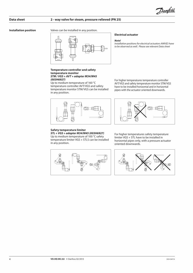
Installation position Valves can be installed in any position.
Electrical actuator
Note!Installation positions for electrical actuators AMV(E) have to be observed as well. Please see relevant Data sheet
Temperature controller and safety temperature monitorSTM / VGS + AVT + adapter M34/M45 (003H6927)Up to medium temperature of 160 °C temperature controller AVT/VGS and safety temperature monitor STM/VGS can be installed in any position.
Safety temperature limiterSTL + VGS + adapter M34/M45 (003H6927)Up to medium temperature of 100 °C safety temperature limiter VGS + STLS can be installed in any position.
ForhighertemperaturestemperaturecontrollerAVT/VGS and safety temperature monitor STM/VGS have to be installed horizontal and in horizontal pipes with the actuator oriented downwards.
Forhighertemperaturessafetytemperaturelimiter VGS + STL have to be installed in horizontal pipes only, with a pressure actuator oriented downwards.

5VD.HD.W2.02 © Danfoss 02/2013DEN-SMT/SI
Data sheet 2 - way valve for steam, pressure relieved (PN 25)
Sizing
Steam valve sizing is based on 40 % drop of the steam pressure across the valve when fully open. At this condition the steam is travelling at or close to its critical velocity (approx. 300 m/s) and throttlingwouldoccuroverthefullvalvestroke.
If the steam is travelling slower than this, then thefirstpartofthevalvestrokewouldmerelyincrease the velocity of the steam without reducing the volumetric flow.
6 VD.HD.W2.02 © Danfoss 02/2013 DEN-SMT/SI
Data sheet 2 - way valve for steam, pressure relieved (PN 25)
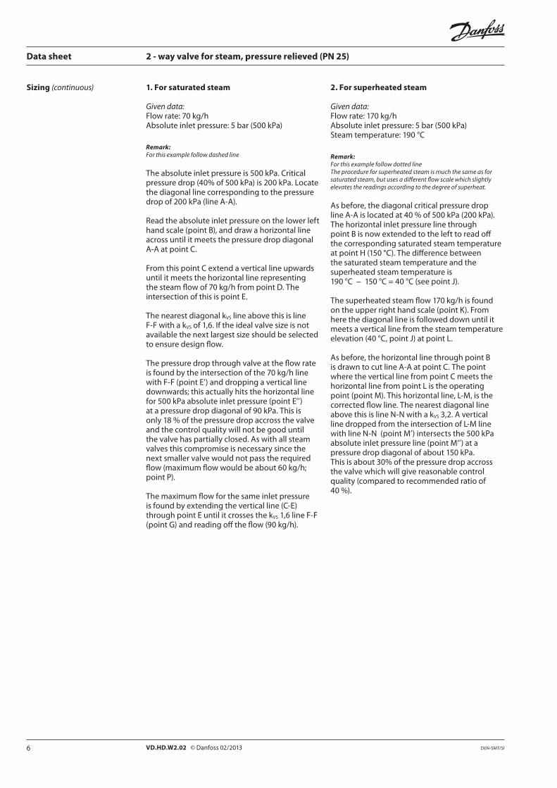
Sizing (continuous) 1. For saturated steam
Given data: Flowrate:70kg/hAbsoluteinletpressure:5bar(500kPa)
Remark:For this example follow dashed line
Theabsoluteinletpressureis500kPa.Criticalpressuredrop(40%of500kPa)is200kPa.Locatethe diagonal line corresponding to the pressure dropof200kPa(lineA-A).
Read the absolute inlet pressure on the lower left hand scale (point B), and draw a horizontal line across until it meets the pressure drop diagonal A-A at point C.
FromthispointCextendaverticallineupwardsuntil it meets the horizontal line representing thesteamflowof70kg/hfrompointD.Theintersection of this is point E.
ThenearestdiagonalkVS line above this is line F-FwithakVS of 1,6. If the ideal valve size is not available the next largest size should be selected to ensure design flow.
The pressure drop through valve at the flow rate isfoundbytheintersectionofthe70kg/hlinewithF-F(pointE’)anddroppingaverticallinedownwards; this actually hits the horizontal line for500kPaabsoluteinletpressure(pointE’’)atapressuredropdiagonalof90kPa.Thisisonly 18 % of the pressure drop accross the valve and the control quality will not be good until the valve has partially closed. As with all steam valves this compromise is necessary since the next smaller valve would not pass the required flow(maximumflowwouldbeabout60kg/h;pointP).
The maximum flow for the same inlet pressure is found by extending the vertical line (C-E) throughpointEuntilitcrossesthekVS1,6lineF-F(pointG)andreadingofftheflow(90kg/h).
2. For superheated steam
Given data:Flowrate:170kg/hAbsoluteinletpressure:5bar(500kPa)Steamtemperature:190°C
Remark:For this example follow dotted lineThe procedure for superheated steam is much the same as for saturated steam, but uses a different flow scale which slightly elevates the readings according to the degree of superheat.
As before, the diagonal critical pressure drop lineA-Aislocatedat40%of500kPa(200kPa).The horizontal inlet pressure line through point B is now extended to the left to read off the corresponding saturated steam temperature at point H (150 °C). The difference between the saturated steam temperature and the superheated steam temperature is 190°C−150°C=40°C(seepointJ).
Thesuperheatedsteamflow170kg/hisfoundontheupperrighthandscale(pointK).Fromhere the diagonal line is followed down until it meets a vertical line from the steam temperature elevation(40°C,pointJ)atpointL.
As before, the horizontal line through point B is drawn to cut line A-A at point C. The point where the vertical line from point C meets the horizontal line from point L is the operating point (point M). This horizontal line, L-M, is the corrected flow line. The nearest diagonal line abovethisislineN-NwithakVS 3,2. A vertical line dropped from the intersection of L-M line withlineN-N(pointM’)intersectsthe500kPaabsoluteinletpressureline(pointM’’)atapressuredropdiagonalofabout150kPa.This is about 30% of the pressure drop accross the valve which will give reasonable control quality (compared to recommended ratio of 40 %).

7VD.HD.W2.02 © Danfoss 02/2013DEN-SMT/SI
Adapter M34 × 1,5 mm / M30 × 1,5 mm
Adapter M34 × 1,5 mm / M45 × 1,5 mm
M34
M45
M34
M30
SW
L3
d R
L2
SW
L1
SW
n
d2
45°
k
L
H
Data sheet 2 - way valve for steam, pressure relieved (PN 25)
Design
1. Valve body 2. Valve insert 3. Pressurerelievedvalvecone 4. Valve stem 5. Valve body extension 6. Stuffing box
Dimensions
DN 15 20 25
VGS
Lmm
65 70 75
H 156,5 155 158,5
Weight kg 0,7 0,8 0,9
DN R 1)SW d L1
2) L2 L3 k d2n
mm
15 1/2 32 (G 3/4A) 21 130 131 139 65 14 4
20 3/4 41 (G 1A) 26 150 144 154 75 14 4
25 1 50 (G 11/4A) 33 160 160 159 85 14 4
1) Conical ext. thread acc. to EN 10226-12) Flanges PN 25, acc. to EN 1092-2
8 VD.HD.W2.02 ProducedbyDanfossA/S©02/2013
Data sheet 2 - way valve for steam, pressure relieved (PN 25)