Embed Size (px)
Citation preview

Standard ECMA-320
June 2001
S t anda rd i z ing In fo rma t ion and Communica t i on Sys t ems
Phone: +41 22 849 .60 .00 - Fax: +41 22 849 .60 .01 - URL: h t tp : / /www.ecma.ch - In ternet : he [email protected]
Data Interchange on 12,7 mm -448-Track Magnetic Tape Cartridges - SDLT1 Format

.

Standard ECMA-320
June 2001
Standa rd i z ing In fo rma t ion and Communica t i on Sys t ems
Phone: +41 22 849 .60 .00 - Fax: +41 22 849 .60 .01 - URL: h t tp : / /www.ecma.ch - In ternet : he [email protected]
MB ECMA-320.doc 18-07-01 10,02
Data Interchange on 12,7 mm -448-Track Magnetic Tape Cartridges - SDLT1 Format

.

Brief History
Technical Committee ECMA TC17 has produced a series of ECMA Standards for magnetic tape cassettes and cartridges of different widths, e.g. 12,7 mm, 8 mm, 6,35 mm and 3,81 mm. In each series, the new standards correspond to specific types of application and different user requirements. Enhanced and new media correspond also to advancements in drive technology. The series of such cartridges with a magnetic tape of 12,7 mm width and longitudinally recorded tracks comprises the following standards.
ECMA-120 (1993) : Data Interchange on 12,7 mm 18-Track Magnetic Tape Cartridges ISO 9661
ECMA-152 (1993) : Data Interchange on 12,7 mm 18-Track Magnetic Tape Cartridges - Extended Format ISO/IEC 11559
ECMA-182 (1992) : Data Interchange on 12,7 mm 48-Track Magnetic Tape Cartridges - DLT 1 Format - ISO/IEC 13421
ECMA-196 (1993) : Data Interchange on 12,7 mm 36-Track Magnetic Tape Cartridges ISO/IEC 14251
ECMA-197 (1993) : Data Interchange on 12,7 mm 112-Track Magnetic Tape Cartridges - DLT 2 Format - ISO/IEC 13962
ECMA-209 (1994) : Data Interchange on 12,7 mm 128-Track Magnetic Tape Cartridges - DLT 3 Format ISO/IEC 14833
ECMA-231 (1995) : Data Interchange on 12,7 mm 128-Track Magnetic Tape Cartridges - DLT 4 Format ISO/IEC 15305
ECMA-258 (1997) : Data Interchange on 12,7 mm 128-Track Magnetic Tape Cartridges - DLT 3-XT Format ISO/IEC 15895
ECMA-259 (1997) : Data Interchange on 12,7 mm 208-Track Magnetic Tape Cartridge - DLT 5 Format ISO/IEC 15896
ECMA-278 (1998) : Data Interchange on 12,7 mm 128-Track Magnetic Tape Cartridge ISO/IEC 17913 Parallel Serpentine Format ECMA-286 (1999) : Data Interchange on 12,7 mm 208-Track Magnetic Tape Cartridge - DLT 6 Format ISO/IEC 16282 ECMA-319 (2001) : Data Interchange on 12,7 mm 384-Track Magnetic Tape Cartridges – Ultrium-1 Format This ECMA Standard is the first of a new family of cartridges containing a linearly recorded 448-track 12,7 mm magnetic tape. It represents a further advance by using a combination of magnetic and optical technologies known as Laser-Guided Magnetic Recording (LGMR). The back surface of the tape presents optically detected servo marks. The format is derived from the DLT Format, it provides for a capacity of 110 Gbytes of uncompressed user data, or typically 220 Gbytes of compressed user data.
All ECMA Standards listed above have been or will be adopted by ISO/IEC as International Standards. The present ECMA Standard has also been contributed to ISO/IEC for adoption as an International Standard under the fast-track procedure.
This Standard has been adopted by the ECMA General Assembly of June 2001.

- i -
Table of contents
1 Scope 1
2 Conformance 1 2.1 Magnet ic tape car t r idges 1 2 .2 Generat ing systems 1 2 .3 Receiving systems 1
3 References 1
4 Definit ions 1 4.1 back surface 1 4 .2 Beginning-Of-Tape marker (BOT) 1 4 .3 block 2 4 .4 byte 2 4 .5 car t r idge 2 4 .6 Cycl ic Redundancy Check (CRC) character 2 4 .7 Error-Detect ing Code (EDC) 2 4 .8 End-Of-Tape marker (EOT) 2 4 .9 Ent i ty 2 4 .10 Error-Correct ing Code (ECC) 2 4 .11 Envelope 2 4 .12 Envelope s ize 2 4 .13 f lux t ransi t ion posi t ion 2 4 .14 f lux t ransi t ion spacing 2 4 .15 logical t rack 2 4 .16 magnet ic tape 2 4 .17 Master Standard Reference Tape 2 4 .18 object 2 4 .19 page 3 4 .20 recording densi ty 3 4 .21 physical t rack 3 4 .22 Record 3 4 .23 Reference Edge 3 4 .24 Reference Field 3 4 .25 Secondary Standard Reference Tape 3 4 .26 Standard Reference Ampli tude (SRA) 3 4 .27 Standard Reference Current 3 4 .28 Test Recording Current 3 4 .29 Typical Field 3
5 Conventions and notat ions 3 5.1 Representat ion of numbers 3 5 .2 Dimensions 4 5 .3 Names 4 5 .4 Acronyms 4
6 Environment and safety 4 6.1 Car tr idge and tape tes t ing environment 4 6 .2 Car tr idge operat ing environment 4 6 .3 Car tr idge s torage environment 5 6 .4 Safety 5

- i i -
6.5 Flammabil i ty 5 6 .5 Transpor ta t ion 5
Sect ion 2 - Requirements for the unrecorded tape 5
7 Mechanical and electrical requirements 5 7.1 Mater ia l 5 7 .2 Tape length 5 7 .3 Tape width 5 7 .4 Tape th ickness 5 7 .5 Discont inui ty 5 7 .6 Longitudinal curvature 5
7 .6 .1 Requirements 5 7 .6 .2 Procedure 6
7 .7 Out-of-Plane dis tor t ions 6 7 .8 Cupping 6 7 .9 Roughness of the coat ing surfaces 6
7 .9 .1 Roughness of the back coat ing surface 6 7 .9 .2 Roughness of the magnet ic coat ing surface 6
7 .10 Coat ing adhesion 6 7 .11 Layer- to- layer adhesion 7
7 .11.1 Requirements 7 7 .11.2 Procedure 7
7 .12 Modulus of e las t ic i ty 8 7 .12.1 Requirement 8 7 .12.2 Procedure 8
7 .13 Flexural r ig id i ty 8 7 .13.1 Requirement 8 7 .13.2 Procedure 8
7 .14 Tensi le yie ld force 8 7 .14.1 Procedure 9
7 .15 Electr ical res is tance 9 7 .15.1 Requirement 9 7 .15.2 Procedure 9
7 .16 Inhibi tor tape 10 7 .17 Light t ransmit tance of the tape and the leader 10 7 .18 Abrasivi ty 10 7 .19 Coeff ic ient of dynamic f r ic t ion 10
7 .19.1 Requirements 10 7 .19.2 Procedure for the measurement of the f r ic t ion between the magnet ic surface and
the back surface 10 7 .19.3 Procedure for the measurement of the f r ic t ion between the magnet ic surface or
the back surface and calc ium t i tanate ceramic 10 7 .20 Servo 11
7 .20.1 Servo Bands 11 7 .20.2 Servo Tracks 11 7 .20.3 Signal 11 7 .20.4 Signal- to Noise Rat io 12 7 .20.5 Miss ing servo mark 12
8 Magnetic recording characterist ics 13

- i i i -
8.1 Typical Field 13 8 .2 Signal ampli tude 13 8 .3 Resolut ion 13 8 .4 Overwri te 13
8 .4 .1 Requirement 13
9 Tape qual i ty 14 9.1 Missing pulses 14
9 .1 .1 Requirement 14 9 .2 Miss ing pulse zone 14
9 .2 .1 Requirement 14 9 .3 Tape durabi l i ty 14
Sect ion 3 - Mechanical specif icat ions of the tape cartridge 14
10 General 14 10.1 Bottom s ide and r ight s ide 15 10.2 Back s ide and lef t s ide 16 10.3 Tape reel 16 10.4 Tape leader 17 10.5 Front s ide 19 10.6 Operat ion of the car t r idge 19 10.7 Tape winding 20 10.8 Moment of iner t ia 20 10.9 Mater ia l 20
Sect ion 4 - Requirements for an interchanged tape 30
11 Tape format 30 11.1 Reference Edge 30 11.2 Direct ion of recording 30 11.3 Tape layout 30
11.3 .1 Data Area 30 11.3 .2 Forward Alignment and Directory Area 32 11.3 .3 Reverse Al ignment Area a t EOT 33
12 Data format 34 12.1 Record 34 12.2 Data Bytes 34 12.3 Data Field 34
12.3 .1 Pages 35 12.3 .2 Pad Bytes 35 12.3 .3 Page layout 35 12.3 .4 MAP entr ies 35 12.3 .5 EDC 36
12.4 Data Blocks 36 12.4 .1 Control Fie ld 1 (CF1) 37 12.4 .2 Control Fie ld 2 (CF2) 38 12.4 .3 CRC 40
13 Method of recording 40 13.1 Physical recording densi ty 41

- iv -
13.2 Channel b i t cel l length 41 13.2 .1 Average Channel b i t cel l length 41 13.2 .2 Long-term average Channel b i t ce l l length 41 13.2 .3 Short- term average Channel b i t ce l l length 41
13.3 Read s ignal ampli tude 41 13.4 Channel skew 41
14 Block Recording Format 42 14.1 Scrambler 42 14.2 Modulat ion 42
14.2 .1 Modulat ion process 42 14.2 .2 Modulated Data Group 43
14.3 Precoder 43 14.4 Recording Data Block 44
14.4 .1 Preamble 44 14.4 .2 Sync 44
15 Types and Use of Blocks 44 15.1 Types of Blocks 44 15.2 Use of b locks 45
15.2 .1 Track ID Star t Blocks 45 15.2 .2 End of Track Blocks (EOTR) 45 15.2 .3 End of Data of Data Blocks (EOD) 45 15.2 .4 ECC Blocks 45 15.2 .5 Track ID End Blocks 45
16 Format of Entit ies 45
17 Format of Envelopes 46
18 Error handling 46
Annex A - Measurement of l ight transmittance 47
Annex B - Procedure for the measurement of abrasivity 51
Annex C - Generat ion of the Data Block CRCs 53
Annex D - Generat ion of page CRCs 55
Annex E - ECC generat ion 57
Annex F - Allocat ion of Physical Tracks to Logical Tracks 61
Annex G - Recommendations for transportat ion 63
Annex H - Inhibitor tape 65
Annex J - Recommendations on tape durabi l i ty 67
Annex K - Handling guidel ines 69
Section 1 - General
1 Scope This ECMA Standard specifies the physical and magnetic characteristics of a 12,7 mm wide, 448-track magnetic tape cartridge, to enable physical interchangeability of such cartridges between drives. It also specifies the quality of the recorded signals, a format - called Super Digital Linear Tape 1 (SDLT 1) - and a recording method, thereby allowing data interchange between drives. Together with a labelling standard, for instance Standard ECMA-13 for Magnetic Tape Labelling, it allows full data interchange by means of such magnetic tape cartridges.
2 Conformance 2.1 Magnetic tape cartridges
A magnetic tape cartridge shall be in conformance with this ECMA Standard if it satisfies all mandatory requirements of this ECMA Standard. The tape requirements shall be satisfied throughout the extent of the tape.
2.2 Generating systems A system generating a magnetic tape cartridge for interchange shall be in conformance with this ECMA Standard if all the recordings that it makes on a tape according to 2.1 meet the mandatory requirements of this ECMA Standard.
In addition, a claim of conformance shall state
− whether or not one, or more registered algorithm(s) are implemented within the system,
− the registered identification number(s) of the implemented compression algorithm(s).
2.3 Receiving systems A system receiving a magnetic tape cartridge for interchange shall be in conformance with this ECMA Standard if it is able to handle any recording made on a tape according to 2.1.
In addition, a claim of conformance shall state
− whether or not one, or more de-compression algorithm(s) are implemented within the system, and are able to be applied to de-compress data prior to making such data available to the host,
− the registered identification number(s) of the implemented compression algorithm(s).
3 References ECMA-13:1985 File Structure and Labelling of Magnetic Tapes for Information Interchange
ECMA-287:1999 Safety of Electronic equipment
ISO 1302:1992 Technical drawings - Method of indicating surface texture on drawings.
ISO/IEC 11576:1994 Information technology - Procedure for the registration of algorithms for the lossless compression of data.
4 Definitions For the purpose of this ECMA Standard, the following definitions apply.
4.1 back surface The surface of the tape opposite the magnetic coating which is used to record data.
4.2 Beginning-Of-Tape marker (BOT) A hole punched on the centreline of the tape towards the end nearest to the leader.

- 2 -
4.3 block A set of contiguous bytes recorded on a physical track and considered as a unit.
4.4 byte An ordered set of bits acted upon as a unit.
NOTE
In this ECMA Standard, all bytes are 8-bit bytes.
4.5 cartridge A case containing a single supply reel of 12,7 mm wide magnetic tape with a leader attached at the outer end.
4.6 Cyclic Redundancy Check (CRC) character A 64-bit character, generated by a mathematical computation, used for error detection.
4.7 Error-Detecting Code (EDC) A mathematical computation yielding check bytes used for error detection.
4.8 End-Of-Tape marker (EOT) A hole punched on the centreline of the tape towards the end farthest from the leader.
4.9 Entity A group of twenty blocks treated as a logical unit.
4.10 Error-Correcting Code (ECC) A mathematical computation yielding check bytes used for the correction of errors detected by the CRC and the EDC.
4.11 Envelope A group of Entities.
4.12 Envelope size The number of Entities in an Envelope.
4.13 f lux transit ion posit ion The point that exhibits the maximum free-space flux density normal to the tape surface.
4.14 f lux transit ion spacing The distance on the magnetic tape between successive flux transitions.
4.15 logical track A group of eight physical tracks that are written or read simultaneously.
4.16 magnetic tape A tape that accepts and retains magnetic signals intended for input, output, and storage purposes on computers and associated equipment.
4.17 Master Standard Reference Tape A tape selected as the standard for Reference Field, signal amplitude, resolution, and overwrite characteristics.
NOTE
The Master Standard Reference Tape has been established by the Quantum Corporation.
4.18 object A Record or a page of type Tape Mark.
- 3 -
4.19 page A logical division of a block.
4.20 recording density The number of recorded flux transitions per unit length of track.
4.21 physical track A longitudinal area on the tape along which a series of magnetic signals can be recorded.
4.22 Record User data processed as described in Clause 12.
4.23 Reference Edge The bottom edge of the tape when viewing the magnetic coating of the tape with the BOT to the left and the EOT to the right of the observer.
4.24 Reference Field The Typical Field of the Master Standard Reference Tape.
4.25 Secondary Standard Reference Tape A tape the characteristics of which are known and stated in relation to those of the Master Standard Reference Tape.
NOTE
Secondary Standard Reference Tapes can be ordered under Reference "SSRT/SDLT1" from Quantum Corporation, 333 South Street, Shrewsbury, Mass. 01545-4195, USA. It is intended that these be used for calibrating tertiary reference tapes for routine calibration.
In principle, these Secondary Standard Reference Tapes will be available for a period of 10 years from the publication of the first version of this ECMA Standard. However, by agreement between ECMA and Quantum Corporation, this period may be changed to take into account the demand for such Secondary Standard Reference Tapes.
4.26 Standard Reference Amplitude (SRA) The Average Signal Amplitude from the Master Standard Reference Tape when it is recorded with the Test Recording Current at 2 700 ftpmm.
4.27 Standard Reference Current The current that produces the Reference Field.
4.28 Test Recording Current The current that is 1,1 times the Standard Reference Current.
4.29 Typical Field In the plot of the Average Signal Amplitude against the recording field at 2 700 ftpmm, the minimum field that causes an Average Signal Amplitude equal to 95 % of the maximum Average Signal Amplitude.
5 Conventions and notations 5.1 Representation of numbers
The following conventions and notations apply in this ECMA Standard, unless otherwise stated.
− A measured value is rounded off to the least significant digit of the corresponding specified value. It implies that a specified value of 1,26 with a positive tolerance +0,01, and a negative tolerance -0,02 allows a range of measured values from 1,235 to 1,275.
− In each block and in each field the bytes shall be arranged with Byte 1, the least significant, first. Within each byte the bits shall be arranged with Bit 1, the least significant, first and Bit 8, the most

- 4 -
significant bit, last. This order applies to the data, and to the input and output of the error-detecting and error-correcting codes, and to the cyclic redundancy characters.
− Letters and digits in parentheses represent numbers in hexadecimal notation.
− The setting of bits is denoted by ZERO or ONE.
− Numbers in binary notation and bit patterns are represented by strings of digits 0 and 1 shown with the most significant bit to the left.
5.2 Dimensions The dimensions in figures 1 to 3 are nominal dimensions. Unless otherwise stated, all dimensions in the other figures are in millimetres with a tolerance of ± 50 mm.
5.3 Names The names of basic elements, e.g. specific fields, are written with a capital initial letter.
5.4 Acronyms BOT Beginning of Tape CAF Coarse Alignment Field CF1 Control Field 1 CF2 Control Field 2 CRC Cyclic Redundancy Check (character) CT1 Calibration Track 1 CT2 Calibration Track 2 FAF1 Fine Alignment Field 1 FAF2 Fine Alignment Field 2 ECC Error-Correcting Code EDC Error-Detecting Code EOD End of Data EOT End of Tape EOTR End of Track SRA Standard Reference Amplitude
6 Environment and safety Unless otherwise stated, the conditions specified below refer to the ambient conditions in the test or computer room and not to those within the tape drive.
6.1 Cartridge and tape testing environment Unless otherwise stated, tests and measurements made on the cartridge and tape to check the requirements of this ECMA Standard shall be carried out under the following conditions:
− temperature: 23 °C ± 2 °C − relative humidity: 40 % to 60 % − conditioning before testing: 24 h min.
6.2 Cartridge operating environment Cartridges used for data interchange shall be capable of operating under the following conditions:
− temperature: 10 °C to 40 °C − relative humidity: 20 % to 80 % − wet bulb temperature: 26 °C max.
NOTE
Localised tape temperatures in excess of 49 °C may cause tape damage.
If during storage and/or transportation a cartridge has been exposed to conditions outside the above values, it shall be conditioned before use by exposure to the operating environment for a time equal to, or greater

- 5 -
than, the time away from the operating environment up to a maximum of 24 h. There shall be no deposit of moisture on or in the cartridge.
6.3 Cartridge storage environment Cartridges shall be stored under the following conditions:
− temperature: 16 °C to 32 °C − relative humidity: 20 % to 80 %
The stray magnetic field at any point on the tape shall not exceed 4000 A/m. There shall be no deposit of moisture on or in the cartridge.
6.4 Safety The cartridge and its components shall satisfy the requirements of Standard ECMA-287 when used in the intended manner or in any foreseeable use in an information processing system.
6.5 Flammability The cartridge and its components shall be made from materials which, if ignited from a match flame and when so ignited, do not continue to burn in a still carbon dioxide atmosphere.
6.5 Transportation This ECMA Standard does not specify parameters for the environment in which cartridges should be transported. Annex G gives some recommendations for transportation.
Section 2 - Requirements for the unrecorded tape The measurements specified in Section 2 shall be performed on an unrecorded tape with servo marks
(See 7.20) on the back surface.
7 Mechanical and electrical requirements 7.1 Material
The tape shall consist of a base material (oriented polyethylene terephthalate film or its equivalent) coated on one surface with a strong yet flexible layer of ferromagnetic material dispersed in a suitable binder. The back surface of the tape shall be coated with a non-ferromagnetic conductive coating.
7.2 Tape length The length of the tape from the leader splice to the hub shall be 558 m ± 1 m.
7.3 Tape width The width of the tape shall be 12,649 mm ± 0,010 mm.
The width shall be measured across the tape from edge to edge when the tape is under a tension of less than 0,28 N.
7.4 Tape thickness The total thickness of the magnetic tape at any point shall be between 8,20 µm and 9,30 µm.
7.5 Discontinuity There shall be no discontinuities in the tape between the BOT and EOT such as those produced by tape splicing or perforations.
7.6 Longitudinal curvature The longitudinal curvature is measured as the departure of the Reference Edge of the tape from a straight line along the longitudinal dimension of the tape in the plane of the tape surface.
7.6.1 Requirements
Any deviation of the Reference Edge from a straight line shall be continuous and shall not exceed 0,076 mm within any 229 mm length of tape.

- 6 -
7.6.2 Procedure
i. Measure at a tension of 1,39 N ± 0,28 N in a test fixture equipped with two guides spaced at 229 mm.
ii. Spring-load the two guides to position the Reference Edge of the tape against two edge control surfaces.
iii. Measure the maximum deviation of the Reference Edge of the tape from the line drawn between the two control surfaces.
7.7 Out-of-Plane distortions All visual evidence of out-of-plane distortion shall be removed when the tape is subjected to a uniform tension of 0,6 N. Out-of-plane distortions are local deformations which cause portions of the tape to deviate from the plane of the surface of the tape. Out-of-plane distortions are most readily observed when the tape is lying on a flat surface under no tension.
7.8 Cupping The departure across the width of the tape from a flat surface shall not exceed 2,54 mm.
Procedure
i. Cut a 1,0 m ± 0,1 m length of tape. Condition it for a minimum of 3 h in the test environment by hanging it so that both surfaces are freely exposed to the test environment.
ii. From the centre portion of the conditioned tape cut a test piece of approximately 25 mm length. Stand the test piece on its end in a cylinder that is at least 25 mm high with an inside diameter of 13,0 mm ± 0,2 mm.
iii. With the cylinder standing on an optical comparator measure the cupping by aligning the edges of the test piece to the reticle and determining the distance from the aligned edges to the corresponding surface of the test piece at its centre.
7.9 Roughness of the coating surfaces 7 .9 .1 Roughness of the back coat ing surface
The back coating surface shall have an arithmetic average roughness Rab between 0,003 µm and 0,027 µm (ISO 1302:N 2). This measurement shall be made using a contacting stylus of radius 12,5 µm with a 20 mg load, and a 254 µm cut-off range.
7.9 .2 Roughness of the magnetic coat ing surface
The magnetic coating surface shall have an arithmetic average roughness Ram between 0,003 µm and 0,008 µm (ISO 1302: N 3). The set up for this measurement shall be identical with that of 7.9.1.
7.10 Coating adhesion The force required to peel any part of the coating from the tape base material shall not be less than 0,016 N.
Procedure
i. Take a test piece of the tape approximately 380 mm long and scribe a line through the recording coating across the width of the tape 125 mm from one end.
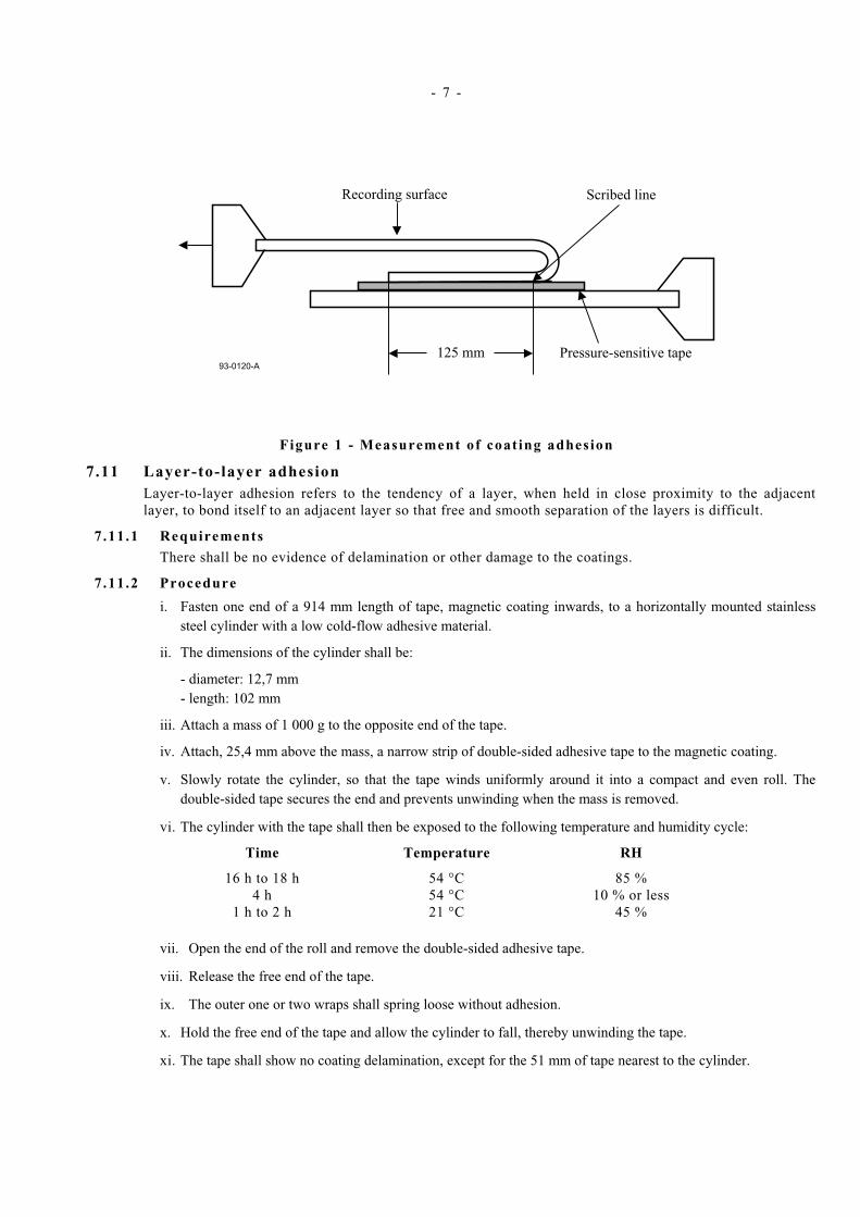
ii. Using a double-sided pressure sensitive tape, attach the full width of the test piece to a smooth metal plate, with the magnetic coating (recording surface) facing the plate, as shown in figure 1.
iii. Fold the test piece over 180°, adjacent to, and parallel with, the scribed line. Attach the metal plate and the free end of the test piece to the jaws of a universal testing machine and set the speed of the jaw separation to 254 mm per min.
iv. Note the force at which any part of the coating first separates from the base material. If this is less than 0,016 N, the tape has failed the test. If the test piece peels away from the double-sided pressure sensitive tape before the force 0,010 N, an alternative type of double-sided pressure sensitive tape shall be used.
v. Repeat i) to iv) for the back coating.
- 7 -
mm125 Pressure-sensitive tape
Scribed lineRecording surface
93-0120-A
Figure 1 - Measurement of coat ing adhesion
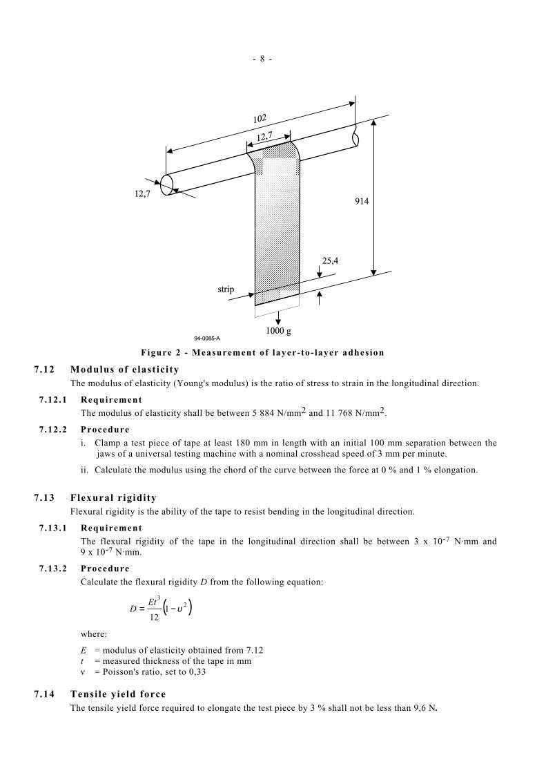
7.11 Layer-to-layer adhesion Layer-to-layer adhesion refers to the tendency of a layer, when held in close proximity to the adjacent layer, to bond itself to an adjacent layer so that free and smooth separation of the layers is difficult.
7.11.1 Requirements
There shall be no evidence of delamination or other damage to the coatings.
7.11.2 Procedure
i. Fasten one end of a 914 mm length of tape, magnetic coating inwards, to a horizontally mounted stainless steel cylinder with a low cold-flow adhesive material.
ii. The dimensions of the cylinder shall be:
- diameter: 12,7 mm - length: 102 mm
iii. Attach a mass of 1 000 g to the opposite end of the tape.
iv. Attach, 25,4 mm above the mass, a narrow strip of double-sided adhesive tape to the magnetic coating.
v. Slowly rotate the cylinder, so that the tape winds uniformly around it into a compact and even roll. The double-sided tape secures the end and prevents unwinding when the mass is removed.
vi. The cylinder with the tape shall then be exposed to the following temperature and humidity cycle:
Time Temperature RH
16 h to 18 h 54 °C 85 % 4 h 54 °C 10 % or less
1 h to 2 h 21 °C 45 %
vii. Open the end of the roll and remove the double-sided adhesive tape.
viii. Release the free end of the tape.
ix. The outer one or two wraps shall spring loose without adhesion.
x. Hold the free end of the tape and allow the cylinder to fall, thereby unwinding the tape.
xi. The tape shall show no coating delamination, except for the 51 mm of tape nearest to the cylinder.
- 8 -
94-0085-A
102
12,7
12,7914
25,4
strip
1000 g1000 g
Figure 2 - Measurement of layer-to- layer adhesion
7.12 Modulus of elasticity The modulus of elasticity (Young's modulus) is the ratio of stress to strain in the longitudinal direction.
7.12.1 Requirement
The modulus of elasticity shall be between 5 884 N/mm2 and 11 768 N/mm2.
7.12.2 Procedure
i. Clamp a test piece of tape at least 180 mm in length with an initial 100 mm separation between the jaws of a universal testing machine with a nominal crosshead speed of 3 mm per minute.
ii. Calculate the modulus using the chord of the curve between the force at 0 % and 1 % elongation.
7.13 Flexural rigidity
Flexural rigidity is the ability of the tape to resist bending in the longitudinal direction.
7.13.1 Requirement
The flexural rigidity of the tape in the longitudinal direction shall be between 3 x 10⁻⁷ N.mm and 9 x 10⁻⁷ N.mm.
7.13.2 Procedure
Calculate the flexural rigidity D from the following equation:
( )23
112
υ−=Et
D
where:
E = modulus of elasticity obtained from 7.12 t = measured thickness of the tape in mm ν = Poisson's ratio, set to 0,33
7.14 Tensile yield force The tensile yield force required to elongate the test piece by 3 % shall not be less than 9,6 N.
- 9 -
7.14.1 Procedure
i. Use a static-weighing-constant-rate-of-grip separation tester capable of indicating the load with an accuracy of 2 %.
ii. Clamp a test piece of tape at least 178 mm long with an initial 102 mm separation between the jaws.
iii. Elongate the test piece at a rate of 51 mm per minute until a minimum elongation of 10 % is reached.
iv. The force required to produce an elongation of 3 % is the tensile yield force.
7.15 Electrical resistance 7.15.1 Requirement
The electrical resistance of any square area of the magnetic coating shall
− be greater than 106 Ω − not exceed 50 x 1012 Ω
The electrical resistance of any square area of the back coating shall
− not exceed 100 x 106 Ω
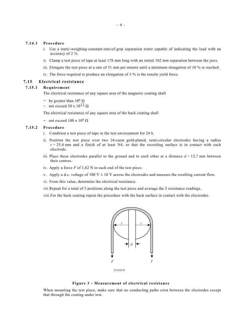
7.15.2 Procedure
i. Condition a test piece of tape in the test environment for 24 h.
ii. Position the test piece over two 24-carat gold-plated, semi-circular electrodes having a radius r = 25,4 mm and a finish of at least N4, so that the recording surface is in contact with each electrode.
iii. Place these electrodes parallel to the ground and to each other at a distance d = 12,7 mm between their centres.
iv. Apply a force F of 1,62 N to each end of the test piece.
v. Apply a d.c. voltage of 100 V ± 10 V across the electrodes and measure the resulting current flow.
vi. From this value, determine the electrical resistance.
vii. Repeat for a total of 5 positions along the test piece and average the 5 resistance readings.
viii. For the back coating repeat the procedure with the back surface in contact with the electrodes.
d
rr
F F
93-0050-B
Figure 3 - Measurement of e lectrical res istance
When mounting the test piece, make sure that no conducting paths exist between the electrodes except that through the coating under test.
- 10 -
NOTE
Particular attention should be given to keeping the surfaces clean.
7.16 Inhibitor tape This ECMA Standard does not specify parameters for assessing whether or not a tape is an inhibitor tape. However, annex H gives further information on inhibitor tapes.
7.17 Light transmittance of the tape and the leader The light transmittance of the tape and the leader shall be less than 5 % when measured according to the method specified in annex A.
7.18 Abrasivity Tape abrasivity is the tendency of the magnetic coating to wear the magnetic heads. When measured according to annex B, the depth of the wear pattern in the specified ferrite bar shall be in the range 45 µm to 65 µm.
7.19 Coefficient of dynamic friction The coefficient of dynamic friction shall be measured between the two surfaces of the tape and between them and calcium titanate ceramic.
7.19.1 Requirements
Between the magnetic surface and the back surface : greater than 0,15 Between the magnetic surface and calcium titanate ceramic: 0,05 to 0,35 Between the back surface and calcium titanate ceramic: 0,05 to 0,20
7.19.2 Procedure for the measurement of the fr ict ion between the magnetic surface and the back surface
i. Wrap a first piece of tape around a calcium titanate ceramic cylinder (Ra = 0,05 µm) of diameter 25,4 mm and wrap it with a total wrap angle of more than 90° with the back surface outwards.
ii. Wrap a second test piece, with the magnetic surface inwards, around the first test piece with a total wrap angle of 90°.
iii. Exert on one end of the outer test piece a force of F1 = 0,64 N.
iv. Attach the other end to a force gauge mounted on a linear slide.
v. Drive the slide at a speed of 1 mm/s, measure the force F2 required.
vi. Calculate the coefficient of dynamic friction γ from the equation
=
1
2ln1
F
F
φγ
where φ is the value of the wrap angle in radians.
7.19.3 Procedure for the measurement of the fr ict ion between the magnetic surface or the back surface and calcium t i tanate ceramic
i. Wrap a piece of tape around a calcium titanate ceramic cylinder (Ra = 0,05 µm) of diameter 25,4 mm and wrap it with a total wrap angle of 90° with the magnetic surface or the back surface, as appropriate, inwards.
ii. Exert on one end of the test piece a force of F1 = 0,64 N.
iii. Attach the other end to a force gauge mounted on a linear slide.
iv. Drive the slide at a speed of 1 mm/s, measure the force F2 required.
v. Calculate the coefficient of dynamic friction γ from the equation
- 11 -
=
1
2ln1
F
F
φγ
where φ is the value of the wrap angle in radians.
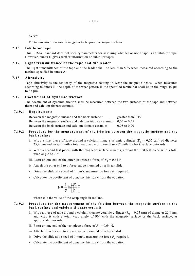
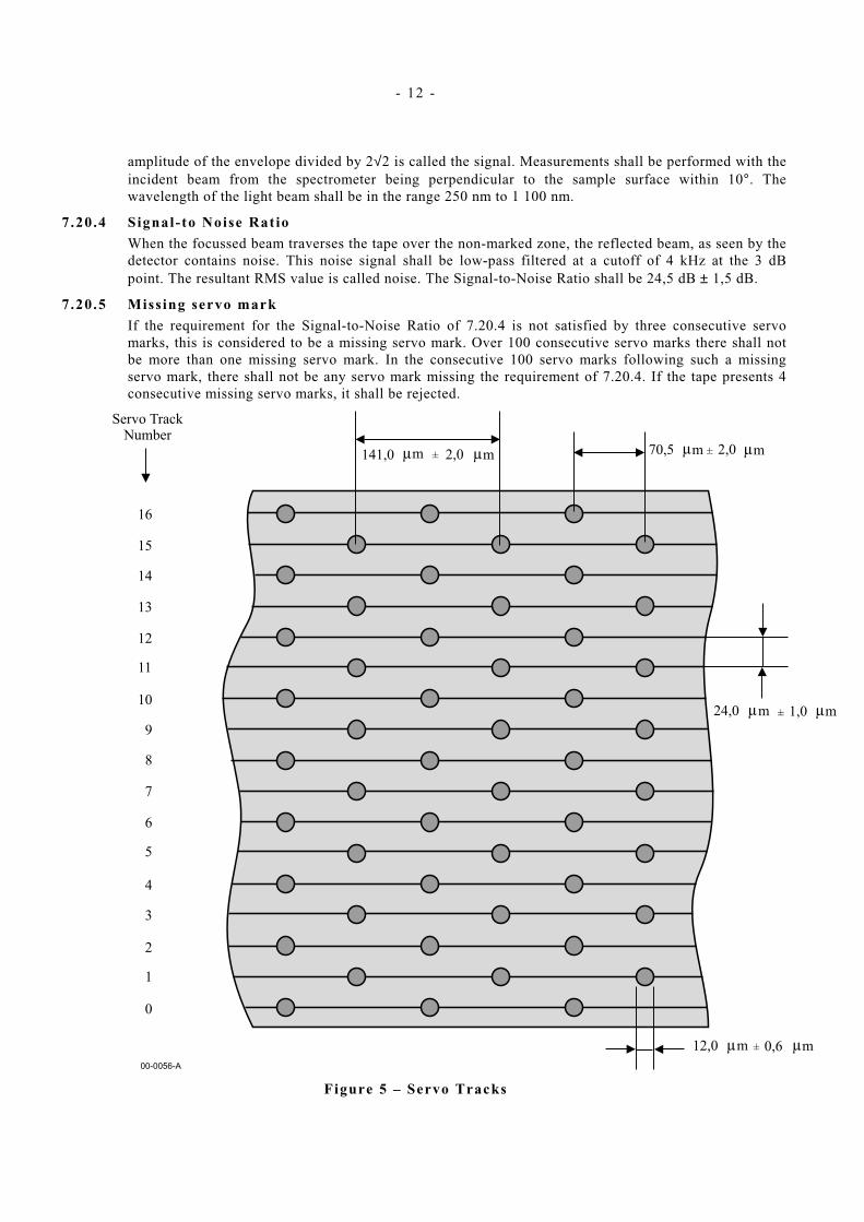
7.20 Servo There shall be four servo bands of 17 servo tracks each. In each servo band these servo tracks shall be numbered 0 to 16. Each servo track shall consist of servo marks recorded on the back side of the tape.
7.20.1 Servo Bands
The four servo bands recorded optically are designated as Servo Bands 0, 1, 2 and 3.
The centreline of Servo Track 0 of Servo Band 0 shall be at a distance of 2,43 mm ± 0,05 mm from the Reference Edge.
All Servo Bands shall be at a distance from their adjacent band(s) of 2,794 0 mm ± 0,018 0 when measured between the centrelines of their respective Servo Track 0.
The cumulative error over the distance between Servo band 0 and Servo band 3 shall not exceed ± 0,0018 0 mm.
Figure 4 – Servo Bands
7.20.2 Servo Tracks
Each servo mark shall have a diameter of 12,0 µm ± 0,6 µm (See figure 5). They shall be at a distance of 141,0 µm ± 2,0 µm from each other. The servo tracks shall be at a distance of 24 µm ± 1 µm from each other. In every second servo tracks the servo marks shall be shifted by 70,5 µm ± 2,0 µm relative to those in the adjacent servo tracks. In each servo band the cumulative tolerance over the distance between Servo Track 0 and Servo Track 16 shall not exceed 1 µm.
7.20.3 Signal
When the optical beam from an optical pickup is focussed on the back side of the moving tape, a series of pulses due to the servo marks will be detected by the detector in the pickup. The modulation
- 12 -
amplitude of the envelope divided by 2√2 is called the signal. Measurements shall be performed with the incident beam from the spectrometer being perpendicular to the sample surface within 10°. The wavelength of the light beam shall be in the range 250 nm to 1 100 nm.
7.20.4 Signal- to Noise Ratio
When the focussed beam traverses the tape over the non-marked zone, the reflected beam, as seen by the detector contains noise. This noise signal shall be low-pass filtered at a cutoff of 4 kHz at the 3 dB point. The resultant RMS value is called noise. The Signal-to-Noise Ratio shall be 24,5 dB ± 1,5 dB.
7.20.5 Miss ing servo mark
If the requirement for the Signal-to-Noise Ratio of 7.20.4 is not satisfied by three consecutive servo marks, this is considered to be a missing servo mark. Over 100 consecutive servo marks there shall not be more than one missing servo mark. In the consecutive 100 servo marks following such a missing servo mark, there shall not be any servo mark missing the requirement of 7.20.4. If the tape presents 4 consecutive missing servo marks, it shall be rejected.
Figure 5 – Servo Tracks

- 13 -
8 Magnetic recording characteristics The magnetic recording characteristics shall be defined by testing the requirements given below.
When performing the tests, the output or resultant signal shall be measured on the same relative pass for both a tape calibrated to the Master Standard Reference Tape and the tape under test (read-while-write, or on equipment without read-while-write capability, on the first forward-read-pass) on the same equipment.
The following conditions shall apply to the testing of all magnetic recording characteristics, unless otherwise noted.
− Tape condition: a.c. erased to 2 % or less of the Average Signal Amplitude
− Tape speed: 2,946 m/s ± 0,029 m/s
− Read track: within the written track
− Gap alignment: the read gap and the write gap to be parallel within 2,54 µm
− Write gap length: 1,00 µm ± 0,10 µm
− Write gap width: 23 µm ± 1 µm
− Read gap length: 0,376 3 µm ± 0,037 6 µm
− Read gap width: 14 µm ± 1 µm
− Tape tension: 0,83 N ± 0,01 N
− Recording current: Test Recording Current
− Physical recording density 5 400 ftpmm ± 100 ftpmm
− Bandwidth of the read amplifier 25,0 MHz
8.1 Typical Field The Typical Field shall be between 85 % and 125 % of the Reference Field.
Traceability to the Reference Field is provided by the calibration factors supplied with each Secondary Standard Reference Tape.
8.2 Signal amplitude The Average Signal Amplitude shall be between 85 % and 115 % of the SRA.
Traceability to the SRA is provided by the calibration factors supplied with each Secondary Standard Reference Tape.
8.3 Resolution The ratio of the Average Signal Amplitude at 2 700 ftpmm to that at 1 350 ftpmm shall be between 85 % and 125 % of the same ratio for the Master Standard Reference Tape.
Traceability to the resolution of the Master Standard Reference Tape is provided by the calibration factors supplied with each Secondary Standard Reference Tape.
8.4 Overwrite Overwrite is the ratio of the residual signal of the Average Signal Amplitude recorded at 675 ftpmm after being overwritten at 5 400 ftpmm to the average signal amplitude of the 675 ftpmm signal.
8.4.1 Requirement
The overwrite for the tape shall be less than 110 % of the overwrite for the Master Standard Reference Tape.
Traceability to the overwrite of the Master Standard Reference Tape is provided by the calibration factors supplied with each Secondary Standard Reference Tape.

- 14 -
9 Tape quality 9.1 Missing pulses
A missing pulse is a loss of read signal amplitude. When a base-to-peak read signal amplitude is less than 40% of half the Average Signal Amplitude (See 8.2) for the preceding 25,4 mm of track, then these 25,4 mm constitute a missing pulse. This measurement shall be carried out in steps of 25,4 mm of track.
9.1.1 Requirement
The average missing pulse rate shall be less than 20 missing pulses for any recorded length of track of 100 m.
9.2 Missing pulse zone A missing pulse zone is a sequence of missing pulses exceeding 100 mm.
9.2.1 Requirement
Missing pulse zones shall not occur.
9.3 Tape durabil ity This ECMA Standard does not specify parameters for assessing tape durability. However, a recommended procedure is described in annex J.
Section 3 - Mechanical specifications of the tape cartridge
10 General The tape cartridge shall consist of the following elements
− a case − a reel for the magnetic tape − a locking mechanism for the reel − a magnetic tape wound on the hub of the reel − a write-inhibit mechanism − a tape leader
Dimensional characteristics are specified for those parameters deemed mandatory for interchange and compatible use of the cartridge. Where there is freedom of design, only the functional characteristics of the elements described are indicated.
Where they are purely descriptive the dimensions are referred to three reference planes A, B, and C forming a geometrical trihedral. Where the dimensions are related to the position of the cartridge in the drive, they may be referenced to another surface of the cartridge.
In the enclosed drawings a typical implementation is represented.
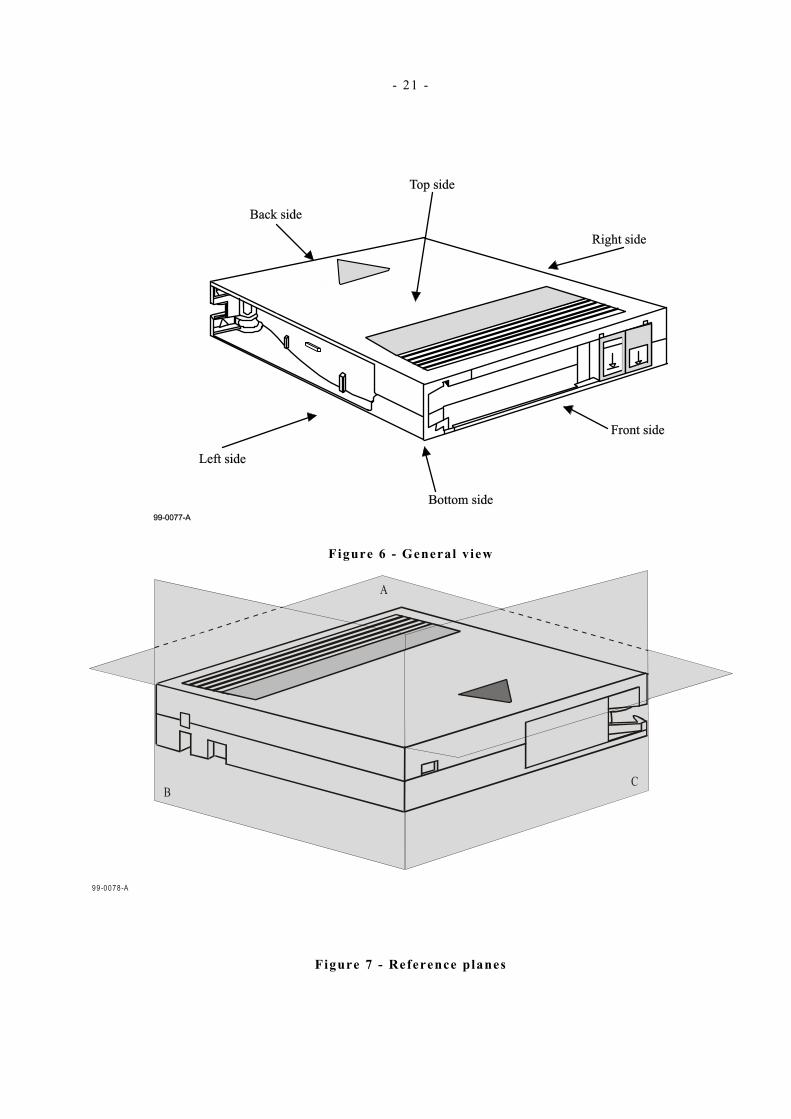
Figure 6 shows a general view of the cartridge. Figure 7 shows the reference planes A, B, C. Figure 8 shows the bottom side of the cartridge. Figure 9 shows the right side of the cartridge. Figure 10 shows the back side of the cartridge with the door closed. Figure 11 shows the left side of the cartridge. Figure 12 shows a partial cross-section of the cartridge in locked position. Figure 13 shows a partial cross-section of the cartridge in operating position. Figure 14 shows the leader-to-tape connection. Figure 15 shows the splice of the leader-to-tape connection. Figure 16 shows a partial top view at a larger scale of the buckle of the leader. Figure 17 shows a perspective view of the relative position of the leader buckle and the take up part before contact. Figure 18 shows a partial, enlarged view of figure 17 Figure 19 shows a perspective view of the relative position of the leader buckle
and the take up part after contact

- 15 -
Figure 20 shows the front side of the cartridge. Figure 21 shows the position of the door lock on the back side of the cartridge. Figure 22 shows the back side of the cartridge with the door open.
Figure 6 shows a general view of the cartridge. When it is not in the operating position, the reel of magnetic tape is locked and cannot rotate. When loaded into the drive, the back side is introduced first and the front side remains visible during operation. During the loading process the tape reel is unlocked and the position of the cartridge within the drive is fixed by elements of the drive engaging with corresponding elements of the case.
The position of the case relative to the reference planes A, B and C is shown in figure 7. The top side lies in reference plane A, the right side lies in reference plane B and the back side lies in reference plane C.
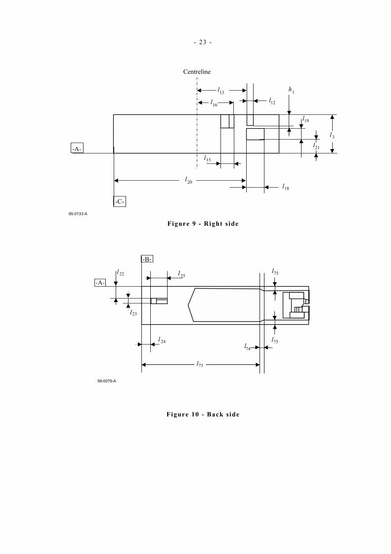
10.1 Bottom side and right side (Figures 8 and 9) The overall dimensions of the cartridge shall be
l1 = 105,79 mm ± 0,20 mm
l2 = 105,41 mm ± 0,20 mm
l3 = 25,40 mm ± 0,25 mm
The bottom side shall have a window the dimensions and the position of which shall be defined by
l4 = 4,85 mm ± 0,05 mm
l5 = 6,25 mm ± 0,10 mm
l6 = 83,61 mm ±0,20 mm
l7 = 3,81 mm ± 0,05 mm
This window allows one of the fingers of the drive to penetrate into the case for partially unlocking the reel of tape (See 10.6).
A positioning hole on the bottom side and a guiding notch, followed by a positioning notch in the right side determine the position of the cartridge in the drive.
The dimensions and the position of the positioning hole shall be defined by
l8 = 21,59 mm ± 0,10 mm
+ 0,13 mm
l9 = 4,45 mm - 0,00 mm
l10 = 2,79 mm ± 0,05 mm
l11 = 44,58 mm ± 0,20 mm
The dimensions and the position of the positioning notch shall be defined by
l12 = 5,56 mm ± 0,10 mm
l13 = 33,60 mm ± 0,20 mm
l14 = 5,08 mm ± 0,10 mm
h1 = 9,02 mm ± 0,10 mm
a1 = 14° ± 30'
The dimensions and the position of the guiding notch shall be defined by
l15 = 8,59 mm ± 0,10 mm
l16 = 24,64 mm ± 0,10 mm
l17 = 1,50 mm ± 0,05 mm
a2 = 45° ± 30'

- 16 -
a3 = 17° ± 30'
The right side shall have an indicator connected to the manually operable write-inhibit switch described in 10.5. The dimensions and the position of this indicator shall be defined by
l18 = 8,64 mm ± 0,10 mm
l19 = 5,08 mm ±0,10 mm
l20 = 86,11 mm ± 0,20 mm
l21 = 10,16 mm ± 0,10 mm
Writing is enabled when the surface of the indicator is substantially flush with the cartridge wall. When this surface is recessed by at least 5,1 mm writing is inhibited. When a force of up to 1,0 N is exerted perpendicularly on the centre of the surface of the indicator, it shall not recede by more than 0,5 mm from reference plane B.
10.2 Back side and left s ide (Figures 8 and 10 and 11) The back side shall have a window the dimensions and position of which shall be
l22 = 8,76 mm ± 0,10 mm
l23 = 4,25 mm ± 0,10 mm
l24 = 4,45 mm ± 0,10 mm
l25 = 8,89 mm ± 0,10 mm
This window allows a further finger of the drive to penetrate into the case to finally unlock the reel of tape (See also 10.6).
A door shall be rotatably mounted at the corner of the back side and the left side. At a distance
l73 = 70,65 mm ± 0,20 mm
from reference plane B, the width of the door is reduced as specified by
l74 = 0,71 mm ± 0,01 mm
l75 = 2,18 mm ± 0,10 mm
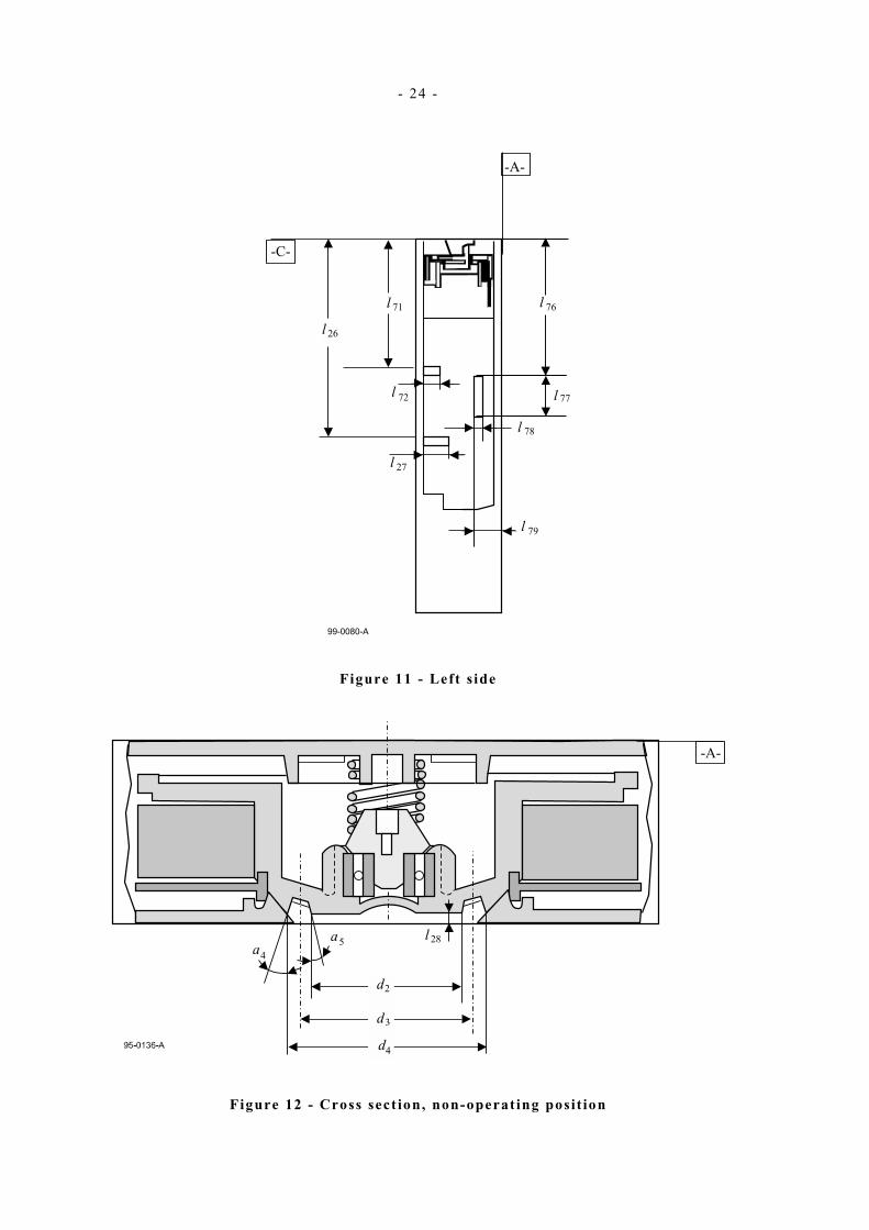
The left side shall have two vertical edges and one horizontal edge the positions and lengths of which shall be
l26 = 61,47 mm ± 0,20 mm
+0,13 mm
l27 = 9,65 mm -0,00 mm
l71 = 41,9 mm ± 0,20 mm
+0,18 mm l72 = 6,18 mm
-0,00 mm
l76 = 47,24 mm ± 0,10 mm
l77 = 16,35 mm ± 0,10 mm
l78 = 1,34 mm ± 0,10 mm
l79 = 11,22 mm ± 0,10 mm
NOTE This horizontal edge is intended to prevent the insertion of the cartridge into a DLT drive.
10.3 Tape reel (Figures 8, 12 and 13) The bottom side of the case shall have a circular window through which the drive spindle contacts the hub of the reel and transmits torque. The diameter of this window shall be

- 17 -
d1 = 35,05 mm ± 0,08 mm
The position of its centre shall be defined by
l69 = 50,42 mm ± 0,31 mm
l70 = 52,83 mm ± 0,10 mm
The interface between the spindle and the hub is provided by 48 evenly spaced teeth in the hub. In the non-operating position, the surface of the hub shall be recessed from the outside surface of the case by
l28 = 0,38 mm ± 0,05 mm
The tooth profile consists of straight flanks. The envelope dimensions of the teeth shall be
d2 = 23,88 mm ± 0,13 mm
d3 = 29,21 mm ± 0,13 mm
d4 = 34,29 mm ± 0,13 mm
a4 = 22° ± 30'
a5 = 15° ± 30'
where d3 is the pitch diameter of the teeth.
In the operating position the surface of the hub shall be at a distance
l29 = 23,55 mm ± 0,10 mm
from reference plane A.
10.4 Tape leader (Figures 14, 15 and 16) The positions of the BOT and EOT relative to the leader/tape connection and to the physical end of the tape shall be as follows.
The BOT shall be at a distance
l30= 13 260 mm ± 100 mm
from the leader/tape connection.
The EOT shall be at a distance
l31= 7 620 mm ± 152 mm
from the physical end of the tape, which is fixed to the hub of the reel. Both the BOT hole and EOT hole shall have a diameter
d5 = 3,60 mm ± 0,10 mm
Figure 15 shows the relative positions of the tape, the leader and the splice tape. They shall be defined by
11,81 mm min.
l32= 20,32 mm max.
l33= 0,25 mm max.
l34= 0,41 mm max.
l35= 0,00 mm min.
l36= 0,20 mm max.
Dimensions l34, l35 and l36 are related to, and depend on, each other. Dimension l35 expresses the requirement that the splice tape shall in no case extend beyond the edges of either the tape or the leader.
There shall be no yield of the splice when a force of 22,2 N max. is applied in longitudinal direction across the splice.

- 18 -
A buckle consisting of two arms fixed to an axis is attached at the end of the leader. Figure 16 shows at an enlarged scale this buckle and a perspective view of a buckle arm. The length of these buckle arms shall be
l80 = 13,51 mm ± 0,13 mm
when measured between their right-hand end and said axis. The distance of the axis of the buckle arms to the end of the leader below the splice shall be
l37 = 425,00 mm ± 0,13 mm
The width of the leader shall be
+0,00 mm
l38 = 12,65 mm -0,10 mm
The axis to which the buckle arms are fixed is attached to the leader so as to be able to rotate freely. It has a middle part with a diameter larger than that of its ends fixed to the buckle arms. These diameters shall be
d6 = 0,91 mm ± 0,13 mm
d7 = 0,71 mm ± 0,25 mm
The attachment of the axis to the leader shall be as defined by
l39 = 5,33 mm ± 0,16 mm
l40 = 3,65 mm ± 0,09 mm
The position of the buckle arms relative to the leader shall be as defined by
l41 = 16,15 mm ± 0,25 mm
l42 = 22,76 mm ± 0,11 mm
l43 = 5,11 mm ± 0,25 mm
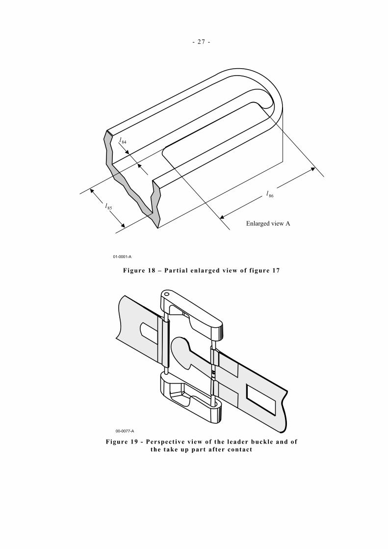
Figures 17 and 18 are a perspective view showing the leader buckle and the take up part of the drive before contact.
The height of the arm shall be
l81 = 3.30 mm ± 0,08 mm
The side opening on the arm shall be
l82 = 5,71 mm ± 0,13 mm
The distance between the end of the arm and the edge of the opening shall be
l83 = 5,76 mm ± 0,13 mm
Figure 18 show a partial view of the inside of the end of an arm as seen in direction A in figure 17. The inside width of the arm shall by
+0,05
l85 = 10,16 mm -0,00
Within the arm there is an inclined surface having a length
l86 = 12,70 mm ± 0,08
There shall be a free space with a width
l84 = 16,16 mm ± 0,13 mm
that allows the take up part of the drive to slide between the wall of the arm and the inclined surface to as to reach its end position shown in figure 19.

- 19 -
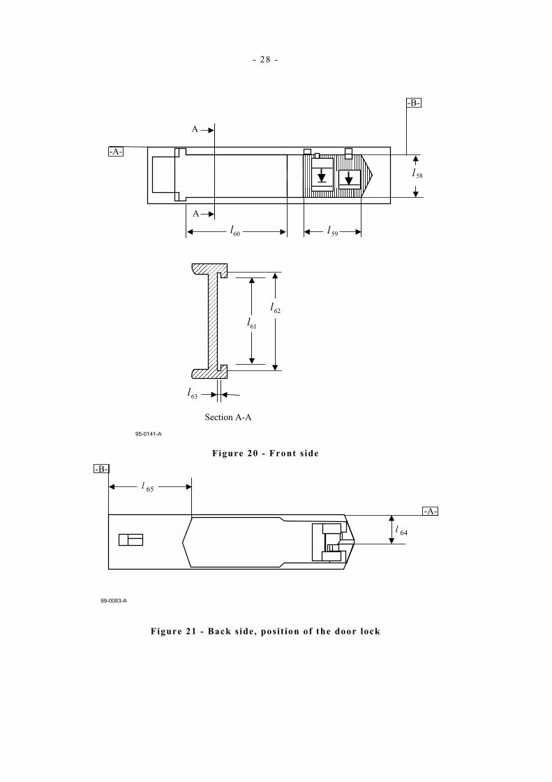
10.5 Front side (Figure 20) The manually operable write-inhibit switch shall have the dimensions
+0,00 mm
l58 = 18,29 mm -0,20 mm
l59= 26,60 mm ± 0,20 mm
This switch shall have a detent at its two end positions. The force depends on the design of the write-inhibit indicator.
The front side shall have a slot intended for labels. The dimensions of this slot shall be
l60 = 54,40 mm ± 0,20 mm
l61 = 18,40 mm ± 0,20 mm
l62 = 21,40 mm ± 0,20 mm
l63 = 0,76 mm ± 0,10 mm
10.6 Operation of the cartridge (Figures 19 and 21) When the cartridge is introduced into the drive, the sequence of events is as follows.
i. The door shall have a movable lock the lower edge of which shall be at a distance
l64 = 14,50 mm ± 0,20 mm
from reference plane A. A cam of the drive raises this lock in order to unlock the door, which shall be unlocked when the edge is raised by 1,0 mm min.
The door is then opened 90° by the drive. It shall be able to rotate further up to 105°. In the open position of the door the whole back side shall be accessible except the part limited by
l65 = 35,79 mm ± 0,20 mm.
In this position the space along the left side that is delimited by
l66 = 4,57 mm ± 0,05 mm
shall be free for a drive element to contact the edge defined by l26 and l27 (See figure 11).
ii. A finger of the drive penetrates into the case through the window defined by l22 to l25 (See figure 10) to partially unlock the reel. The corresponding part of the locking mechanism shall not require a penetration longer than 9 mm nor a force larger than 3,7 N for actuation.
iii. When the cartridge has been completely introduced into the drive, it is held in position by elements of the drive engaging the positioning notch of the right side (Figures 8 and 9) and the positioning hole in the bottom side (Figure 9).
A second finger of the drive penetrates through the window of the bottom side defined by l4 to l7 (See figure 8) and completely unlocks the reel. The requirements for penetration and force are the same as specified in ii. for the first finger.
iv. The drive spindle engages the teeth of the hub and raises the reel into the operating position (See figure 13). The force with which the tape reel is held against the spindle shall be 6,0 N ± 0,5 N.
v. When the cartridge is within the drive in the operating position (Figures 13 and 19), the tape is pulled out of the cartridge by a drive leader attached to the hub of a reel within the drive. The tip of this drive leader is designed so as to match the shape of the buckle of the tape leader and to engage it. The case shall have an abutment against which the buckle comes to rest when the tape is completely pulled back into the cartridge.
vi. The tape leader and the abutment shall withstand the impact of having to stop the full reel when the tape leader is retracted with a speed in the range 152 mm/s to 178 mm/s. Until the reel is fully locked,
- 20 -
i.e. until the cartridge is ejected from the drive, the buckle shall be held against the abutment with a force in the range 1,1 N to 1,7 N.
10.7 Tape winding The tape shall be wound on the hub with the magnetic coating facing inwards, so that during forward read/write operation the tape is unwound from the cartridge reel in a counterclockwise direction when viewed from the top of the cartridge.
The tape shall be wound with a tension of 1,11 N ± 0,28 N.
10.8 Moment of inertia A full reel of tape shall have a diameter between 87,45 mm and 91,19 mm.
The moment of inertia shall be:
− Full reel: Between 131 × 10-6 kg· m2 and 160 × 10-6 kg· m2
− Empty reel: Between 19 × 10-6 kg· m2 and 23 × 10-6 kg· m2
10.9 Material The cartridge can be made of any material as long as the requirements of this ECMA Standard are met. For example, the hub and the case could be made of 10 % glass-filled polycarbonate. A typical wall thickness is 1,5 mm.
The tape leader shall be made of a non-translucent material, for instance pigmented polyethylene terephthalate.
- 21 -
99-0077-A
Left sideLeft side
Back sideBack side
Top sideop side
Right sideRight side
Front sideFront side
Bottom sideBottom side
Figure 6 - General view
99-0078-A
A
BC
Figure 7 - Reference planes

- 22 -
Figure 8 - Bottom side
- 23 -
Figure 9 - Right s ide
Figure 10 - Back s ide
- 24 -
Figure 11 - Left s ide
Figure 12 - Cross sect ion, non-operat ing posit ion

- 25 -
Figure 13 - Cross sect ion, operat ing posit ion
Figure 14 - Leader/tape connect ion
Figure 15 - Posit ion of the spl ice tape

- 26 -
Figure 16 - Enlarged top view of the buckle
Figure 17 – Perspect ive view of the leader buckle and of the take up part before contact
- 27 -
Figure 18 – Part ial enlarged view of f igure 17
Figure 19 - Perspect ive view of the leader buckle and of the take up part after contact
- 28 -
Figure 20 - Front s ide
Figure 21 - Back s ide, posit ion of the door lock

- 29 -
Figure 22 - Back s ide with the door open

- 30 -
Section 4 - Requirements for an interchanged tape
11 Tape format 11.1 Reference Edge
The Reference Edge shall be the bottom edge when viewing the magnetic coating of the tape with the BOT to the left and the EOT to the right of the observer.
11.2 Direction of recording Recording shall take place in two directions:
− forward: from BOT to EOT − reverse: from EOT to BOT
11.3 Tape layout The tape shall be partitioned into three areas:
− the Data Area − the Forward Alignment and Directory Area, − The Reverse Alignment Area
Figure 23 – Tape Layout
11.3 .1 Data Area
The Data Area shall contain data that is transmitted by the host to the drive and recorded according to the format specified in clause 12. The quantity of recorded data may be such that the total capacity of the maximum number of physical tracks, viz., 448, is required in order to contain it. It may, under other circumstances, be less in which case fewer than 448 physical tracks will be required. The following specification is based on the former case.
11.3 .1 .1 Physical tracks
There shall be 448 physical tracks in the Data Area, each identified by a Physical Track Number from 1 to 448. Physical Track 448 shall be that farthest from the Reference Edge and Physical Track 1 shall be that nearest to the Reference Edge. The physical tracks are grouped into 4 Recording Bands of 112 physical tracks each.
11.3 .1 .2 Width of the physical tracks
The width of a physical track shall be 0,023 mm ± 0,001 mm.

- 31 -
11.3 .1 .3 Posit ions of the physical tracks
In each band the centreline of the first forward physical track shall be at 1,906 5 mm ± 0,002 0 from centreline of the 9th servo track in each band.
The distance between the centrelines of all adjacent forward and all adjacent reverse tracks in all bands shall be 0,024 mm ± 0,001 mm.
The distance between the last forward track and the following reverse track in all bands shall be 0,026 mm ± 0,001 mm.
The distance between the physical tracks of each logical track shall be 0,343 mm ± 0,010 mm.
11.3 .1 .4 Forward tracks (Figure 25)
The physical tracks with an odd Physical Track Number shall be recorded in the forward direction, i.e. from BOT to EOT, The recording shall start at 8 458 mm ± 50 mm from the BOT and continue until 1 525 mm max. before the EOT.
11.3.1 .5 Reverse tracks (Figure 26)
The physical tracks with an even Physical Track Number shall be recorded in the reverse direction, i.e. from EOT to BOT. The recording shall start at 8 458 mm ± 50 mm from the EOT and continue until 1 525 mm max. before the BOT.
11.3 .1 .6 Logical tracks
A logical track shall consist of eight physical tracks recorded and read simultaneously.
Logical tracks are identified by a Logical Track Number from 0 to 55. They are recorded in ascending order of their Logical Track Numbers, starting with Logical Track No. 0.
Logical tracks with an even Logical Track Number shall be recorded in the forward direction on physical tracks with an odd Physical Track Number.
Logical tracks with an odd Logical Track Number shall be recorded in the reverse direction on physical tracks with an even Physical Track Number.
The allocation of physical tracks to logical tracks shall be as specified in annex F.
There shall be Track ID Start Blocks (See 15.2.1) written at the start of each logical track. These blocks shall be recorded over 1 000 mm ± 100 mm, starting at the beginning of the Data Area, viz. at 8 458 mm ± 50 mm from the BOT or the EOT.
There shall be a minimum of one complete Envelope of Track ID End Blocks (See 15.2.5) recorded immediately after the Track ID Start Blocks.
Data blocks containing data from the host and processed as described in clause 12 shall be recorded immediately after the Track ID End Blocks.

- 32 -
Figure 24 – Data Area
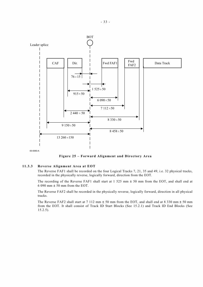
11.3.2 Forward Alignment and Directory Area
The Coarse Alignment Field (CAF) shall be recorded on Logical Track 6, i.e. eight physical tracks, recorded in the forward direction.
The CAF field shall start at 9 150 mm ± 0,50 mm from the BOT and shall end at 2 440 mm ± 50 mm from the BOT. This field shall consist of flux transitions at 1 350 ftpmm.
The Directory Area shall be recorded in the same physical tracks as the CAF.
The Directory Area shall start from 915 mm ± 50 mm from the BOT and end at 76 mm ± 15 mm from the BOT. Its content is not specified by this ECMA Standard and shall be ignored in interchange.
The Forward Fine Alignment Field 1 (FAF1) shall be recorded on the four Logical Tracks 6, 20, 34 and 48, i.e. 32 physical tracks, recorded in the forward direction after the BOT.
The FAF1 shall start at 1 525 mm ± 50 mm from the BOT, and shall end at 6 090 mm ± 50 mm from the BOT. This field shall consist of flux transitions at 1 350 ftpmm.
The Forward Fine Alignment Field 2 (FAF2) shall be recorded on all physical tracks.
The Forward FAF2 shall start at 7 112 mm ± 50 mm from the BOT, and shall end at 8 330 mm ± 50 mm from the BOT.
The FAF2 field shall consist of Track ID Start Blocks (See 15.2.1) and Track ID End Blocks (See 15.2.5).
- 33 -
Figure 25 – Forward Alignment and Directory Area
11.3 .3 Reverse Al ignment Area at EOT
The Reverse FAF1 shall be recorded on the four Logical Tracks 7, 21, 35 and 49, i.e. 32 physical tracks, recorded in the physically reverse, logically forward, direction from the EOT.
The recording of the Reverse FAF1 shall start at 1 525 mm ± 50 mm from the EOT, and shall end at 6 090 mm ± 50 mm from the EOT.
The Reverse FAF2 shall be recorded in the physically reverse, logically forward, direction in all physical tracks.
The Reverse FAF2 shall start at 7 112 mm ± 50 mm from the EOT, and shall end at 8 330 mm ± 50 mm from the EOT. It shall consist of Track ID Start Blocks (See 15.2.1) and Track ID End Blocks (See 15.2.5).

- 34 -
Figure 26 – Reverse Al ignment Area
12 Data format 12.1 Record
The host transmits to the drive data in form of records, each comprising one or more bytes. The interpretation of these bytes is outside the scope of this ECMA Standard and a matter of agreement between the interchange parties.
If the number of bytes of a record received from the host is not a multiple of 4, it is completed by 1, 2 or 3 Pad Bytes, as appropriate. A 32-bit CRC is computed over the bytes of the record or completed record according to annex D and appended to the record or completed record. A record or completed record together with its CRC shall be referred to as a Record. The maximum size of a Record shall be (224-1) bytes.
12.2 Data Bytes Data Bytes shall be
− The bytes of a Record
− 8-byte MAP entries (See 12.3.4)
− Pad Bytes, as required (See 12.3.2)
12.3 Data Field Records shall be arranged in groups of 4 096 Data Bytes to form a Data Field structured as shown in figure 27.

- 35 -
Byte position Number of bytes
Field
1 to … Variable Page 1: Record 1 and CRC
* Variable Page 2: Record 2 and CRC
* * *
* * *
* * *
* Variable Page (n-1): Record (n-1) and CRC
* Variable Page n: Record n and CRC
* Variable Pad Bytes as required
* 8 MAP of page n
* 8 MAP of page (n-1)
* * *
* * *
* * *
4 084 to 4 077 8 MAP of page 2
4 092 to 4 085 8 MAP of page 1
4 096 to 4 093 4 EDC
Figure 27 – Data Field
12.3 .1 Pages
A page shall contain a Record or a part of a Record of variable length.
12.3 .2 Pad Bytes
Pad Bytes shall be set to all ZEROs. After the last page, the Data Field shall be completed with Pad Bytes. There shall be no MAP Entry (See 12.3.4) for these bytes. The Page Type shall be Filler (See figure 25). No new page shall start if 16 bytes or less remain in the Data Field. There shall be no MAP entry for these bytes.
12.3 .3 Page layout
The number of bytes in a page shall always be a multiple of 4.
a) In each page a Record shall be followed by an additional 32-bit Record CRC (See annex D), except as specified below.
b) If the total number of Data Bytes of a Record and its CRC in a page is a multiple of 4, this page is followed by the next page, if any.
c) If a Record or part of a Record comprises 4 096 bytes, its CRC shall be recorded in the first page of the next Data Field. The content of this first page shall consist of this CRC.
12.3 .4 MAP entries
Each MAP entry shall consist of 8 bytes. It specifies attributes of a page. The content of each MAP entry shall be as specified in figure 28. The MAP entry for Record 1 is recorded in the byte positions 4 092 to 4 085 of the Data Field, that of Record 2 in positions 4 084 to 4 077 and so on, i.e "upward" as seen in figure 27.
- 36 -
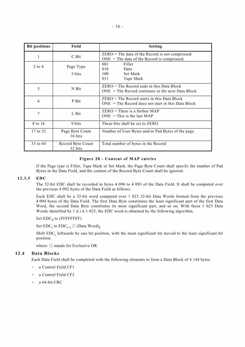
Bit positions Field Setting
1 C Bit ZERO = The data of the Record is not compressed
ONE = The data of the Record is compressed.
2 to 4 Page Type
3 bits
001 Filler 010 Data 100 Set Mark 011 Tape Mark
5 N Bit ZERO = The Record ends in this Data Block ONE = The Record continues in the next Data Block
6 P Bit ZERO = The Record starts in this Data Block ONE = The Record does not start in this Data Block
7 L Bit ZERO = There is a further MAP ONE = This is the last MAP
8 to 16 9 bits These bits shall be set to ZERO
17 to 32 Page Byte Count 16 bits
Number of User Bytes and/or Pad Bytes of the page
33 to 64 Record Byte Count 32 bits
Total number of bytes in the Record
Figure 28 - Content of MAP entries
If the Page type is Filler, Tape Mark or Set Mark, the Page Byte Count shall specify the number of Pad Bytes in the Data Field, and the content of the Record Byte Count shall be ignored.
12.3 .5 EDC
The 32-bit EDC shall be recorded in bytes 4 096 to 4 093 of the Data Field. It shall be computed over the previous 4 092 bytes of the Data Field as follows.
Each EDC shall be a 32-bit word computed over 1 023 32-bit Data Words formed from the previous 4 094 bytes of the Data Field. The first Data Byte constitutes the least significant part of the first Data Word, the second Data Byte constitutes its most significant part, and so on. With these 1 023 Data Words identified by 1 ≤ i ≤ 1 023, the EDC word is obtained by the following algorithm.
Set EDC0 to (FFFFFFFF)
Set EDCi to EDCi-1 ⊕ (Data Word)i
Shift EDCi leftwards by one bit position, with the most significant bit moved to the least significant bit position.
where: ⊕ stands for Exclusive OR.
12.4 Data Blocks Each Data Field shall be completed with the following elements to form a Data Block of 4 144 bytes.
− a Control Field CF1
− a Control Field CF2
− a 64-bit CRC

- 37 -
Number of Bytes Field
4096 Data Field
16 CF1
24 CF2
8 CRC
Figure 29 – Data Block
12.4 .1 Control Fie ld 1 (CF1)
CF1 is a 128 - bit field. It specifies attributes of a block.
The content of CF1 shall be as shown in figure 30
Bit positions
Field name Length in bits
1 to 16 Logical Block Number or Sequential File Mark Offset
16
17 to 28 Sequential File Mark Number 12
29 Logical Block Number Valid 1
30 to 32 These bits shall be set to ZERO 3
33 to 56 Set Mark Number 24
57 to 64 Compression 8
65 to 88 Tape Mark Number 24
89 and 90 These bits shall be set to ZERO 2
91 to 96 Format 6
97 to 128 Object Number 32
Figure 30 - Content of Control Field 1
This format is not applicable to ECC Blocks (See 15.2.4).
12.4.1 .1 Logical Block Number / Sequential Fi le Mark Offset
The contents of this field specify either the Logical Block Number or the Sequential File Mark Offset. The selection depends on the setting of the LBN Valid bit (See 12.4.1.3).
The Logical Block Number shall specify in binary notation the ordinal number of the blocks in each Record starting with 1 for the first block and incremented by 1 for each subsequent block recorded in the same Record.
Each block may contain data and/or a File Mark. In a block no page shall follow the File Mark. If there are subsequent File Marks in this group, they shall be recorded one File Mark per block in sequential blocks.
The Sequential File Mark Offset field shall specify in binary notation the number of File Marks within such a group of sequential File Marks.
12.4.1 .2 Sequential Fi le Mark Number
This field is a count of the number of sets of at least two or more consecutive blocks (See 15.1) having pages of type Tape Mark starting with 1 and incremented by 1 for each such set. These sets may be separated by one or more Data Blocks having no page of type Tape Mark.

- 38 -
12.4 .1 .3 LBN Valid
This bit shall be set to ZERO to indicate that the bytes specified in 12.4.1.1 represent the Sequential File Mark Offset. This bit shall be set to ONE to indicate that these bytes represent the Logical Block Number.
For EOTR and EOD Blocks (See 15.2.2 and 15.2.3), this bit shall be set to ZERO.
12.4 .1 .4 Set Mark Number
This field shall be set to all ZEROs for all blocks prior to the first one containing a page of type Set Mark. In this first block containing a page of type Set Mark, this field shall also be set to all ZEROs.
For Data Blocks this field shall specify in binary notation the ordinal number of the previous Data Block containing a page of type Set Mark.
For EOTR and EOD Blocks, this field shall be set to all ZEROs.
12.4 .1 .5 Compression Type
This field shall specify in binary notation a numerical identifier of the compression algorithm, where applicable, else it shall be set to all ZEROs (See ISO/IEC 11576).
12.4.1 .6 Tape Mark Number
This field shall be set to all ZEROs for all blocks prior to the first one containing a page of type Tape Mark.
For Data Blocks this field shall specify in binary notation the ordinal number of the previous Data Block containing a page of type Tape Mark.
For EOTR and EOD Blocks, this field shall be set to all ZEROs.
12.4 .1 .7 Format
This field shall be set to 001010.
12.4.1 .8 Object Number
This field is a count of all Records and pages of type Tape Mark on the tape, starting with 1 and incremented by 1 for each Record and each page of type Tape Mark.
The content of this field in EOTR and EOD Blocks shall be set to all ZEROs.
12.4 .2 Control Fie ld 2 (CF2)
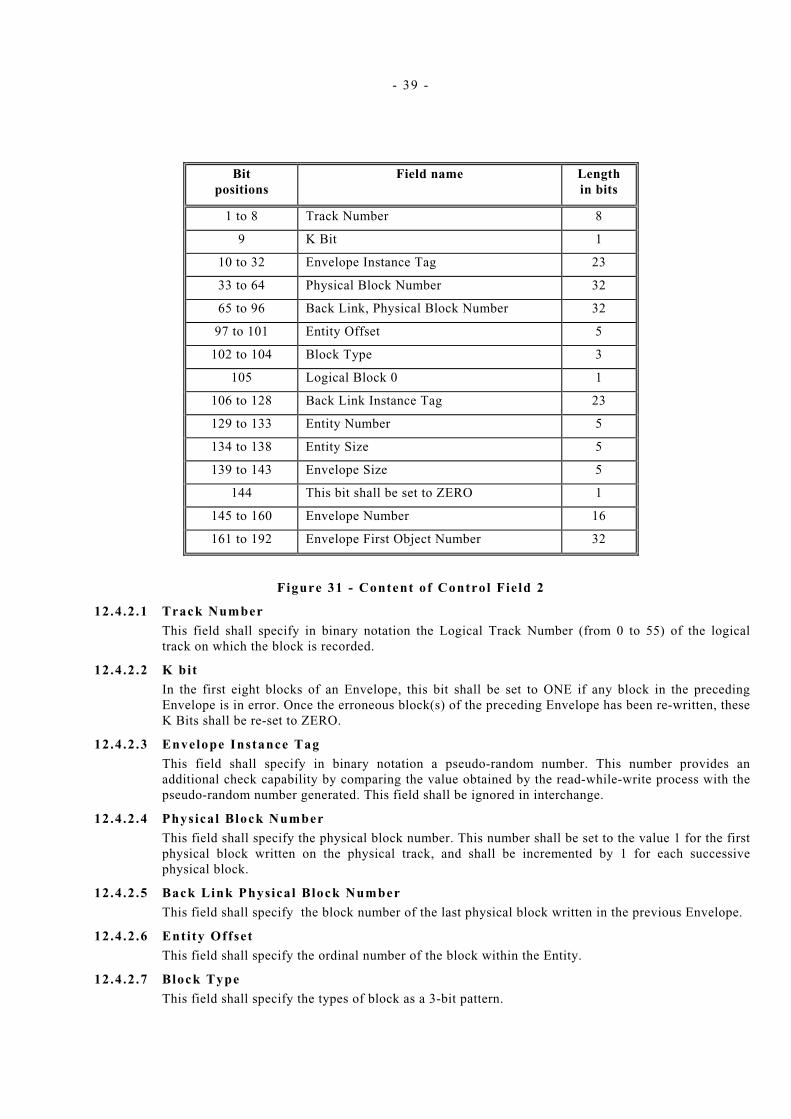
CF2 is a 192-bit field. It specifies further attributes of a block, of the Entity and of the Envelope in which it is recorded. The content of CF2 shall be as shown in figure 31.
- 39 -
Bit positions
Field name Length in bits
1 to 8 Track Number 8
9 K Bit 1
10 to 32 Envelope Instance Tag 23
33 to 64 Physical Block Number 32
65 to 96 Back Link, Physical Block Number 32
97 to 101 Entity Offset 5
102 to 104 Block Type 3
105 Logical Block 0 1
106 to 128 Back Link Instance Tag 23
129 to 133 Entity Number 5
134 to 138 Entity Size 5
139 to 143 Envelope Size 5
144 This bit shall be set to ZERO 1
145 to 160 Envelope Number 16
161 to 192 Envelope First Object Number 32
Figure 31 - Content of Control Field 2
12.4 .2 .1 Track Number
This field shall specify in binary notation the Logical Track Number (from 0 to 55) of the logical track on which the block is recorded.
12.4 .2 .2 K bit
In the first eight blocks of an Envelope, this bit shall be set to ONE if any block in the preceding Envelope is in error. Once the erroneous block(s) of the preceding Envelope has been re-written, these K Bits shall be re-set to ZERO.
12 .4 .2 .3 Envelope Instance Tag
This field shall specify in binary notation a pseudo-random number. This number provides an additional check capability by comparing the value obtained by the read-while-write process with the pseudo-random number generated. This field shall be ignored in interchange.
12.4 .2 .4 Physical Block Number
This field shall specify the physical block number. This number shall be set to the value 1 for the first physical block written on the physical track, and shall be incremented by 1 for each successive physical block.
12.4.2 .5 Back Link Physical Block Number
This field shall specify the block number of the last physical block written in the previous Envelope.
12.4 .2 .6 Entity Offset
This field shall specify the ordinal number of the block within the Entity.
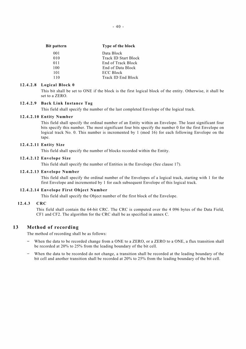
12.4 .2 .7 Block Type
This field shall specify the types of block as a 3-bit pattern.
- 40 -
Bit pattern Type of the block
001 Data Block 010 Track ID Start Block 011 End of Track Block 100 End of Data Block 101 ECC Block 110 Track ID End Block
12.4 .2 .8 Logical Block 0
This bit shall be set to ONE if the block is the first logical block of the entity. Otherwise, it shall be set to a ZERO.
12.4 .2 .9 Back Link Instance Tag
This field shall specify the number of the last completed Envelope of the logical track.
12.4 .2 .10 Entity Number
This field shall specify the ordinal number of an Entity within an Envelope. The least significant four bits specify this number. The most significant four bits specify the number 0 for the first Envelope on logical track No. 0. This number is incremented by 1 (mod 16) for each following Envelope on the tape.
12.4 .2 .11 Entity Size
This field shall specify the number of blocks recorded within the Entity.
12.4 .2 .12 Envelope Size
This field shall specify the number of Entities in the Envelope (See clause 17).
12.4 .2 .13 Envelope Number
This field shall specify the ordinal number of the Envelopes of a logical track, starting with 1 for the first Envelope and incremented by 1 for each subsequent Envelope of this logical track.
12.4.2 .14 Envelope First Object Number
This field shall specify the Object number of the first block of the Envelope.
12.4 .3 CRC
This field shall contain the 64-bit CRC. The CRC is computed over the 4 096 bytes of the Data Field, CF1 and CF2. The algorithm for the CRC shall be as specified in annex C.
13 Method of recording The method of recording shall be as follows:
− When the data to be recorded change from a ONE to a ZERO, or a ZERO to a ONE, a flux transition shall be recorded at 20% to 25% from the leading boundary of the bit cell.
− When the data to be recorded do not change, a transition shall be recorded at the leading boundary of the bit cell and another transition shall be recorded at 20% to 25% from the leading boundary of the bit cell.

- 41 -
0
1
0
1
1
0
0
Figure 32 – Method of Recording
13.1 Physical recording density The recording density averaged over two bit cells shall be in the range 675 ftpmm to 5 400 ftpmm.
13.2 Channel bit cel l length The nominal Channel bit cell length is 0,185 2 µm.
13.2 .1 Average Channel bit ce l l length
The average Channel bit cell length is the overall length of n Channel bit cells divided by n.
13.2 .2 Long-term average Channel bit ce l l length
The long-term average Channel bit cell length shall be the average Channel bit cell length taken over a minimum of 1 000 000 Channel bit cells. It shall be within 2,25 % of the nominal Channel bit cell length.
13.2 .3 Short-term average Channel bit ce l l length
The short-term average Channel bit cell length shall be the average taken over 10 Channel bit cells. It shall be within 5 % of the nominal Channel bit cell length.
13.3 Read signal amplitude The signal amplitude shall be measured at a point in the read channel where the signal is proportional to the rate of change of flux in the read head.
The Average Signal Amplitude of an interchanged cartridge shall be between 75 % and 125 % of the SRA.
Averaging for the interchanged cartridge may be segmented into blocks. No missing pulses shall occur within the measured area.
Traceability to the SRA is provided by the calibration factors supplied with each Secondary Standard Reference Tape.
13.4 Channel skew The deviation between corresponding Channel bits on the physical tracks of a logical track (See 11.3.1.6) shall not exceed 200 Channel bit cell lengths for any pair of such physical tracks.
- 42 -
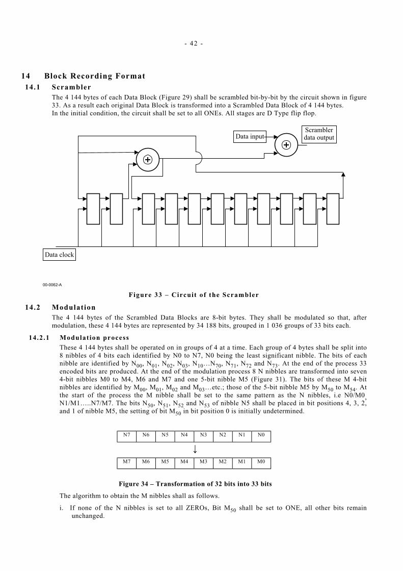
14 Block Recording Format 14.1 Scrambler
The 4 144 bytes of each Data Block (Figure 29) shall be scrambled bit-by-bit by the circuit shown in figure 33. As a result each original Data Block is transformed into a Scrambled Data Block of 4 144 bytes. In the initial condition, the circuit shall be set to all ONEs. All stages are D Type flip flop.
Figure 33 – Circuit of the Scrambler
14.2 Modulation The 4 144 bytes of the Scrambled Data Blocks are 8-bit bytes. They shall be modulated so that, after modulation, these 4 144 bytes are represented by 34 188 bits, grouped in 1 036 groups of 33 bits each.
14.2 .1 Modulat ion process
These 4 144 bytes shall be operated on in groups of 4 at a time. Each group of 4 bytes shall be split into 8 nibbles of 4 bits each identified by N0 to N7, N0 being the least significant nibble. The bits of each nibble are identified by N00, N01, N02, N03, N10…N70, N71, N72 and N73. At the end of the process 33 encoded bits are produced. At the end of the modulation process 8 N nibbles are transformed into seven 4-bit nibbles M0 to M4, M6 and M7 and one 5-bit nibble M5 (Figure 31). The bits of these M 4-bit nibbles are identified by M00, M01, M02 and M03…etc.; those of the 5-bit nibble M5 by M50 to M54. At the start of the process the M nibble shall be set to the same pattern as the N nibbles, i.e N0/M0, N1/M1…..N7/M7. The bits N50, N51, N52 and N53 of nibble N5 shall be placed in bit positions 4, 3, 2, and 1 of nibble M5, the setting of bit M50 in bit position 0 is initially undetermined.
N7 N6 N5 N4 N3 N2 N1 N0
↓
M7 M6 M5 M4 M3 M2 M1 M0
Figure 34 – Transformation of 32 bits into 33 bits
The algorithm to obtain the M nibbles shall as follows.
i. If none of the N nibbles is set to all ZEROs, Bit M50 shall be set to ONE, all other bits remain unchanged.

- 43 -
ii. If one N nibble is set to all ZEROs, Bits M50 shall be set to ZERO, Bit M52 shall be set to ONE, Bit M54, M53 and M51 shall specify the ordinal number of the N nibble set to all ZEROs, all other bits remain unchanged. Unless nibble N5 is set to all ZEROs, the data from this nibble N5 shall be written into the M nibble having the same ordinal number as the N nibble set to all ZEROs.
iii. If two N nibbles are set to all ZEROs, Bits M50 and M52 shall be set to ZERO, bit M43 shall be set to ONE, Bits M51, M53 and M55, shall specify the ordinal number of one of the N nibbles that is set to all ZEROs. Bits M42, M41 and M40 shall specify the ordinal number of the other N nibble that is set to all ZEROs. The setting of all other bits shall remain unchanged. The data from the N5 nibble shall be written into the left-hand side M nibble corresponding to the N nibble set to all ZEROs. The data from the N4 nibble shall be written into the M nibble corresponding to the second N nibble set to all ZEROs to the right-hand side of the second N nibble set to all ZEROs.
iv. If 3 or more N nibble are set to all ZEROs, Bits M51 and M33 shall be set to ZERO, Bits M54 and M53, M42, M41, M40, M32, M31 and M30 shall be set to ONE for each of the N nibble set to all ZEROs. All N nibbles not set to all ZEROs shall be assigned to the corresponding M nibbles as required. Where there are 4 or more nibbles set to all ZEROs, the M nibbles that are still set to all ZEROs, shall be set to ONE. Nibbles N3, N4 and N5 are assigned to M nibbles known to have been set to all ZEROs.
14.2 .2 Modulated Data Group
A Postamble of 168 bits shall be added to these 1 036 groups, so that the complete Modulated Data Group consists of 34 356 bits. This Postamble shall be obtained by means of the circuit of figure 35. All stages shall be Type D flip flop. At the start of the computation they shall be set to 1000.
Figure 35 - Circuit of the Postamble
14.3 Precoder The Modulated Data Group shall be then processed through the Precoder of figure 36. Both stages shall be Type D flip flop. The corresponding algorithm is Yn = Xn ⊕ Yn-2. In the initial state the precoder shall be set to ZERO ZERO.

- 44 -
Figure 36 – Circuit of the Precoder
14.4 Recording Data Block The Recording Data Block shall consist of the Precoded Data Block completed with a Preamble and a Sync preceding it. This Preamble and this Sync shall not be processed according to clause 13.
14.4 .1 Preamble
The Preamble shall consist of 800 bit cell times. There shall be a flux transition at the end of the gap preceding the Preamble field. The Preamble field shall consist of flux transitions at intervals of 4 bit cell times. This shall be done 200 times.
14.4 .2 Sync
The Sync shall consist of 37 bit cell times. A flux transition shall occur at the following bit cell intervals : 9 9 9 2 2 2 2.
Representation Field
800 bit cells Preamble
37 bit cells Sync
34 356 bits Precoded Data Block
Figure 37 – Recording Data Block
15 Types and Use of Blocks 15.1 Types of Blocks
There shall be six types of blocks.
− Data Blocks − Track ID Start Blocks − End of Track Blocks (EOTR) − End of Data Blocks (EOD) − ECC Blocks − Track ID End Blocks
- 45 -
Blocks shall have the format shown in figure 29 (See 12.4). This figure shows a Data Block. All blocks, except ECC Blocks (See 15.2.4) shall have the same structure, but their Data Field shall not contain user data.
15.2 Use of blocks 15.2 .1 Track ID Start Blocks
Track ID Blocks shall be located in the FAF2 only.
The Data Field of the Track ID Block is not specified by this ECMA Standard and shall be ignored in interchange. The Physical Block Number in the Control Field 2 of these blocks shall be set to (FFFF). The K Bit in the Control Field 2 of these blocks shall be set ONE.
15.2 .2 End of Track Blocks (EOTR)
If the Envelope has been completely written, and there is less than 3 048 mm but more than 1 524 mm left to the BOT or EOT, then at least 74 EOTR Blocks shall be recorded on tape and the recording completed. If the Envelope is not completed, and there is less than 3 048 mm but more than 1 524 mm left to the BOT or EOT, a minimum of 74 EOTR blocks shall be recorded on tape and the recording ended. The completed Envelope is then recorded at the start of the next logical track.
The content of the Data Field of an EOTR Block is not specified by this ECMA Standard and shall be ignored in interchange.
15.2 .3 End of Data of Data Blocks (EOD)
At least one Envelope of 120 EOD Blocks shall be recorded to indicate the end of the data recorded on the tape.
The content of the Data Field of an EOD Block is not specified by this ECMA Standard and shall be ignored in interchange.
15.2 .4 ECC Blocks
The bytes of the four ECC Blocks shall be computed over the 4 096 bytes of the Data Field and the 16 bytes of CF1 of the preceding blocks of an Entity. The ECC check bytes shall be recorded in byte positions 0001 to 4112, thus the CF1 of ECC Blocks consist only of the 4-byte field.
The CF2 of ECC Blocks shall be as specified in 12.4.2.
The ECC Blocks shall be completed by a CRC computed as specified in 12.4.3.
Annex E specifies how the ECC bytes shall be computed.
15.2 .5 Track ID End Blocks
Track ID End Blocks shall be located in the FAF2 only, immediately following the Track ID Start Blocks. The Physical Block Number in the Control Field 2 of these blocks shall be set to ZERO and the K Bit in shall be set to ONE. A minimum of one complete Envelope shall be written.
The content of the Data Field of the Track ID End Block is not specified by this ECMA Standard and shall be ignored in interchange.
16 Format of Entities All blocks, except EOTR and EOD Blocks, shall be recorded in Entities. An Entity shall be recorded entirely on the same logical track. It shall consist of 20 blocks numbered consecutively from 1 to 20. At least block No. 1 shall be a Data Block. Blocks No. 2 to No. 16 shall be either Data Blocks or repeated Data Blocks.
− Block No. 17 shall be the ECC1 Block
− Block No. 18 shall be the ECC2 Block
− Block No. 19 shall be the ECC3 Block
− Block No. 20 shall be the ECC4 Block.
- 46 -
After computation of the ECC Blocks, the Data Blocks and the ECC Blocks are recorded on the tape. Each block shall be preceded by a gap consisting of a d.c. erased portion of tape of a nominal length of 100 bytes in 57 mm of which the read signal is less than 5 % of the Average Signal Amplitude.
17 Format of Envelopes Entities shall be grouped in Envelopes. The number of Entities of an Envelope constitutes its size and shall be in the range 1 to 8. Each Entity within an Envelope shall be identified by its Entity Number (12.4.2.10) related to that Envelope. Envelopes shall not span logical tracks. After a write command from the host, recording shall start in a new Envelope immediately after the Envelope to which the append point is targeted. From this point on all existing data shall be overwritten. Within an Envelope, the blocks are recorded in any order on the physical track of the logical track.
18 Error handling When a block is in error, it shall be re-written on any other physical track of the same logical track until it is written successfully (See also 12.4.2.2).

- 47 -
Annex A (normative)
Measurement of light transmittance
A.1 Introduction The following description outlines the general principle of the measuring equipment and measuring method to be applied when measuring the light transmittance of the tape.
For the purpose of this ECMA Standard light transmittance is defined by convention as the relationship between the reading obtained from the measuring equipment with the test piece inserted and the reading obtained when no test piece is present. The transmittance value is expressed as the percentage ratio of the two readings. The requirement of a value of less than 5 % shall be met for the two wavelengths specified in A.2.1.
A.2 Description of the measuring equipment The equipment shall comprise:
− the radiation source, − the radiation receiver, − the measuring mask, − the optical path, − the measuring circuitry.
A.2.1 Radiation source Two infra-red light-emitting diodes (LED) with the following parameters shall be used successively:
LED No. l
Wavelength at peak emission : 750 nm ± 50 nm
Half-power bandwidth : ± 50 nm
LED No. 2
Wavelength at peak emission : 1 050 nm ± 50 nm
Half-power bandwidth : ± 50 nm
A.2.2 Radiation receiver A flat silicon photo diode shall be used. It shall be operated in the short-circuit mode.
A.2.3 Measuring mask The measuring mask shall have a thickness of 2 mm and a circular aperture of diameter d such that the area is 80 % to 100 % of the active area of the photo diode.
The surface of the mask shall be mat black.
The test piece shall be held firmly against the mask to cover the aperture and to ensure that no ambient light leaks past.

- 48 -
A.2.4 Optical path (Figure A.1) The optical path shall be perpendicular to the mask. The distance L from the emitting surface of the LED to the mask shall be
mmtan2 αd
L =
where α is the angle where the relative intensity of the LED is not less than 95 % of the maximum intensity of the optical axis.
A.2.5 Finish The whole assembly shall be enclosed in a mat black case.
A.2.6 Measuring circuitry (Figure A.2) The components of the measuring circuitry are:
E : regulated power supply with variable output voltage
R : current-limiting resistor
LED : light-emitting diode
Di : silicon photo diode
A : operational amplifier
Rf0, Rf1 : feedback resistors
S : gain switch
V : voltmeter
The forward current of the LED, and consequently its radiation power, can be varied by means of the power supply E.
Di is operating in the short circuit mode.
The output voltage of the operational amplifier is given by
V0 = Ik x Rf where Ik is the short-circuit current of Di.
The output voltage is therefore a linear function of the light intensity.
R and Rf1 shall be low temperature-drift resistors with an accuracy of 1 %.
The following ratio applies:
201
R
R
1f
0f =
A.3 Measuring method Set switch S to position 0.
With no test piece mounted, vary the supply voltage of E until voltmeter V reads full scale (100 %).
Mount a test piece of magnetic tape on the mask. Set switch S to position 1. Full deflection of the voltmeter now represents a light transmittance of 5 %.
Apply the method twice, once with LED No. 1 and once with LED No. 2.

- 49 -
M ask
Tap e
L E D
L
S ilic o n p h o to d io d e
O ptica l a x is
d
93-0123-A
2
Figure A.1 - Optical arrangement
R f 0
R f 1 1
S
V
-
+
AD i
R
E
93-0124-B
0
L E D
Figure A.2 - Measuring circuitry

- 50 -

- 51 -
Annex B (normative)
Procedure for the measurement of abrasivity
B.1 General Tape abrasivity is the tendency of the tape to wear the tape transport.
B.2 Test fixture Install a clean ferrite wear bar made as shown in figure B.1 on a holding fixture similar to that shown in figure B.2. Test edge facing upward shall be unworn and free of chips or voids greater than 1 µm in size. The radius of the test edge shall not exceed 13 µm.
The ferrite bar shall consist of polycrystalline ferrite. It shall have the following weight percentages expressed in mole weight:
MgO 30 % ZnO 17 % Fe2O3 53 %
It shall be 99 % dense. It shall have a hardness Knoop of 500.
The surface finish on all four sides of the bar shall be at least of roughness grade N2, 0,05 µm.
The wear bar shall be square within 0,05 mm.
NOTE
Such material is available under reference MND5200 from Ceramic Magnetics Inc., 16 Law Drive in Fairfield (NJ 07004).
B.3 Procedure Install the test fixture (clause B.2) on a tape transport so that the wrap angle of the tape over the bar is 8° on each side, for 16° of total wrap;
Set the tape tension at the bar at 1,4 N.
With a tape speed of 2,54 m/s, make 600 passes (300 cycles) of the tape over the wear bar. The length of tape passing over the wear bar shall be 300,0 m ± 3,0 m.
Remove the holding fixture from the transport and measure the length of the flat worn on the wear bar. This measurement is most easily made using a microscope of known magnification, a camera, and a reference reticule. Magnification of 300X or higher is recommended.
Measurements shall be taken at the 1/4, 1/2, and 3/4 points of the 12,65 mm width of the wear pattern. Take the average length calculated from the three readings. Figure B.3 shows a typical wear pattern and the points of measurements.
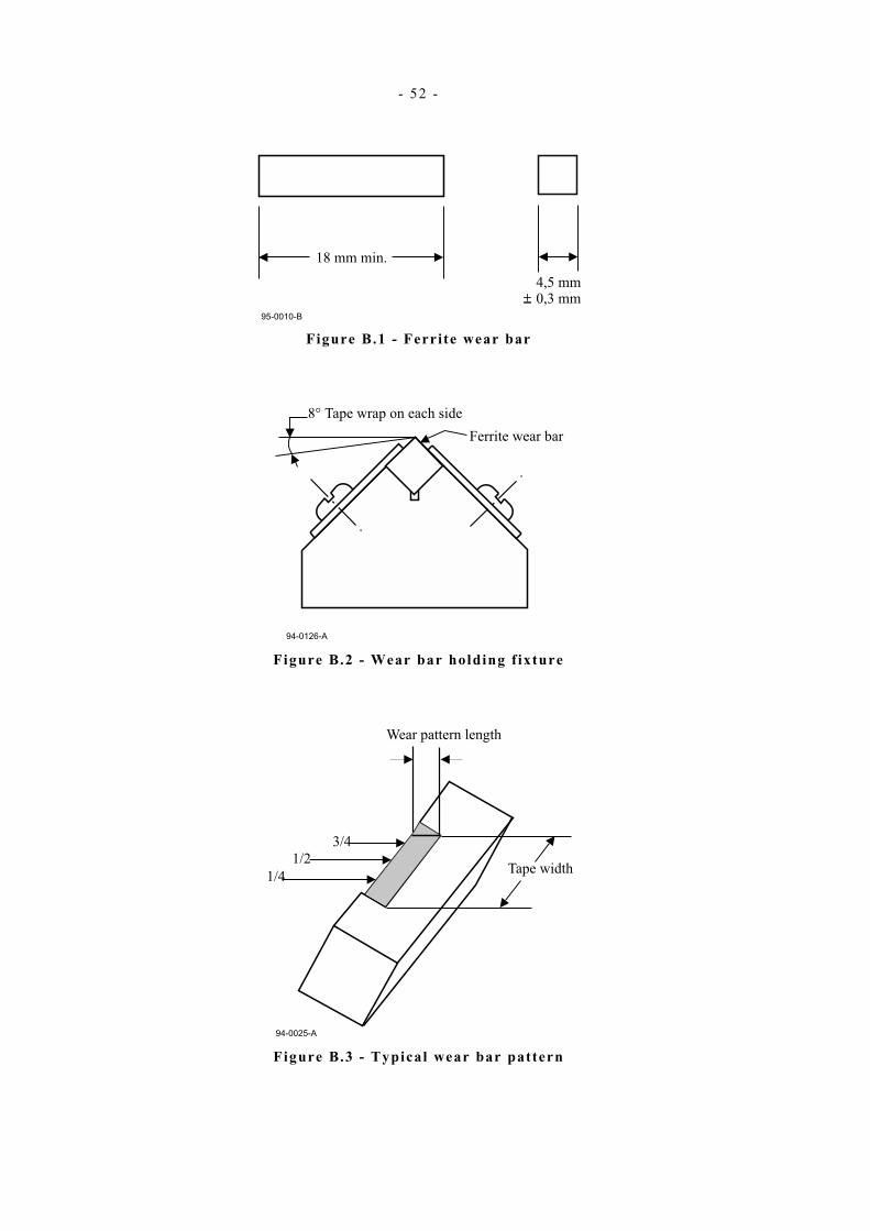
- 52 -
Figure B.1 - Ferrite wear bar
8° Tape wrap on each side
Ferrite wear bar
94-0126-A
Figure B.2 - Wear bar holding f ixture
94-0025-A
3/4
1/2
1/4Tape width
Wear pattern length
Figure B.3 - Typical wear bar pattern

- 53 -
Annex C
(normative)
Generation of the Data Block CRCs
The CRC field shall be recorded as a 64-bit check character computed over the 33 088 bits of the first 4 136 bytes of the Data Block, starting with the first byte of the Data Field and ending with the last byte of CF2.
These bits, with b0 being the low-order bit, shall be the coefficients of the polynomial:
ii
ii xbxM ∑
=
=
=33088
0
)(
Let P(x) = M(x) x64
The generating polynomial shall be
G(x) = x64 + x62 + x57 + x55 + x54 + x53 + x52 + x47 + x46 + x45 + x40 + x39 + x38 + x37 + x35 + x33 + x32 + x31 + x29 + x27 + x24 + x23 + x22 + x21 + x19 + x17 + x13 + x12 + x10 + x9 + x7 + x4 + x + 1
The 64-bit CRC character shall be the remainder of the division of P(x) by G(x).

- 54 -

- 55 -
Annex D (normative)
Generation of page CRCs
The CRC in each page shall be a 32-bit check character computed over the k bits of the Record or completed Record contained in the page.
These k bits b0 to bk-1, where b0 is the low order bit, shall be the coefficient of the polynomial
M(x) = ∑−1
0
ki
i xb
Let P(x) = M(x)x32.
The remainder of the division of P(x) by the generator polynomial
x32 + x26 + x23 + x22 + x16 + x12 + x11 + x10 + x8+ x7 + x5 + x4 + x2 + x + 1
shall constitute the 32-bit CRC.

- 56 -

- 57 -
Annex E (normative)
ECC generation
E.1 The four ECC Blocks are designated by ECC1, ECC2, ECC3 and ECC4 (See clause 15). Each 8-bit byte of the ECC Blocks is computed over the corresponding bytes in the Data Fields, Pad bytes and CF1 of the first 16 blocks of an Entity. Thus, for each of the ECC Blocks:
ECC1 (Byte i), ECC2 (Byte i), ECC3 (Byte i) and ECC4 (Byte i) are based on:
Block 1 (Byte i), Block 2 (Byte i), Block 3 (Byte i) ... and Block 16 (Byte i).
E.2 Each byte of the ECC Blocks is computed as follows. − At the start of each ECC computation RS1 Byte (i,0), RS2 Byte (i,0), RS3 Byte (i,0) and RS4 Byte (i,0) are
set to all ZEROs, where i indicates the position of the byte in the block. − After passing each group of 16 bytes through the Reed-Solomon generator: ECC1 Byte (i) → RS1 Byte (i,16) ECC2 Byte (i) → RS2 Byte (i,16) ECC3 Byte (i) → RS3 Byte (i,16) ECC4 Byte (i) → RS4 Byte (i,16)

- 58 -
E.3 Figure C.1 summarises this process. In this figure i represents the position of the byte and j the Data Block number (j = 1 to 16).
Figure E.1 - ECC Blocks

- 59 -
E.4 The matrices shown in figure C.1 shall be as follows. - Matrix 4
07 = i7 xor i6 xor i5 xor i1; 06 = i6 xor i5 xor i4 xor i0; 05 = i5 xor i4 xor i3; 04 = i4 xor i3 xor i2; 03 = i6 xor i5 xor i3 xor i2; 02 = i7 xor i6 xor i4 xor i2; 01 = i7 xor i3; 00 = i7 xor i6 xor i2.
- Matrix 3
07 = i7 xor i5 xor i4 xor i3 xor i2 xor i1; 06 = i7 xor i6 xor i4 xor i3 xor i2 xor i1 xor i0; 05 = i6 xor i5 xor i3 xor i2 xor i1 xor i0; 04 = i7 xor i5 xor i4 xor i2 xor i1 xor i0; 03 = i6 xor i5 xor i2 xor i0; 02 = i7 xor i3 xor i2; 01 = i7 xor i6 xor i5 xor i4 xor i3; 00 = i6 xor i5 xor i4 xor i3 xor i2.
- Matrix 2
07 = i5 xor i3 xor i2; 06 = i4 xor i2 xor i1; 05 = i3 xor i1 xor i0; 04 = i2 xor i0; 03 = i5 xor i3 xor i2 xor i1; 02 = i5 xor i4 xor i3 xor i1 xor i0; 01 = i7 xor i5 xor i4 xor i0; 00 = i6 xor i4 xor i3.
- Matrix 1
07 = i7 xor i6 xor i5 xor i4; 06 = i7 xor i6 xor i5 xor i4 xor i3; 05 = i6 xor i5 xor i4 xor i3 xor i2; 04 = i7 xor i5 xor i4 xor i3 xor i2 xor i1; 03 = i5 xor i3 xor i2 xor i1 xor i0; 02 = i6 xor i5 xor i2 xor i1 xor i0; 01 = i7 xor i6 xor i1 xor i0; 00 = i7 xor i6 xor i5 xor i0.

- 60 -

- 61 -
Annex F
(normative)
Allocation of Physical Tracks to Logical Tracks
Band
No.
Logical
Tracks
Physical Tracks
Odd Forward
Logical
Tracks
Physical Tracks
Even Reverse
0 0 1 15 29 43 57 71 85 99 1 8 22 36 50 64 78 92 106
0 2 2 16 30 44 58 72 86 100 3 9 23 37 51 65 79 93 107
0 4 3 17 31 45 59 73 87 101 5 10 24 38 52 66 80 94 108
0 6 4 18 32 46 60 74 88 102 7 11 25 39 53 67 81 95 109
0 8 5 19 33 47 61 75 89 103 9 12 26 40 54 68 82 96 110
0 10 6 20 34 48 62 76 90 104 11 13 27 41 55 69 83 97 111
0 12 7 21 35 49 63 77 91 105 13 14 28 42 56 70 84 98 112
1 14 113 127 141 155 169 183 197 211 15 120 134 148 162 176 190 204 218
1 16 114 128 142 156 170 184 198 212 17 121 135 149 163 177 191 205 219
1 18 115 129 143 157 171 185 199 213 19 122 136 150 164 178 192 206 220
1 20 116 130 144 158 172 186 200 214 21 123 137 151 165 179 193 207 221
1 22 117 131 145 159 173 187 201 215 23 124 138 152 166 180 194 208 222
1 24 118 132 146 160 174 188 202 216 25 125 139 153 167 181 195 209 223
1 26 119 133 147 161 175 189 203 217 27 126 140 154 168 182 196 210 224
2 28 225 239 253 267 281 295 309 323 29 232 246 260 274 288 302 316 330
2 30 226 240 254 268 282 296 310 324 31 233 247 261 275 289 303 317 331
2 32 227 241 255 269 283 297 311 325 33 234 248 262 276 290 304 318 332
2 34 228 242 256 270 284 298 312 326 35 235 249 263 277 291 305 319 333
2 36 229 243 257 271 285 299 313 327 37 236 250 264 278 292 306 320 334
2 38 230 244 258 272 286 300 314 328 39 237 251 265 279 293 307 321 335
2 40 231 245 259 273 287 301 315 329 41 238 252 266 280 294 308 322 336
4 42 337 351 365 379 393 407 421 435 43 344 358 372 386 400 414 428 442
4 44 338 352 366 380 394 408 422 436 45 345 359 373 387 401 415 429 443
4 46 339 353 367 381 395 409 423 437 47 346 360 374 388 402 416 430 444
4 48 340 354 368 382 396 410 424 438 49 347 361 375 389 403 417 431 445
4 50 341 355 369 383 397 411 425 439 51 348 362 376 390 404 418 432 446
4 52 342 356 370 384 398 412 426 440 53 349 363 377 391 405 419 433 447
4 54 343 357 371 385 399 413 427 441 55 350 364 378 392 406 420 434 448

- 62 -
- 63 -
Annex G (informative)
Recommendations for transportation
G.1 Environment It is recommended that during transportation the cartridges be kept within the following conditions:
G.1.1 Unrecorded cartridges Temperature : 23 °C to 48 °C Relative humidity : 5 % to 100 % Duration : 10 consecutive days max.
There shall be no condensation in or on the cartridge.
G.1.2 Recorded cartridges Temperature : 5 °C to 32 °C Relative humidity : 5 % to 80 %
There shall be no condensation in or on the cartridge.
G.2 Hazards Transportation of recorded cartridges involves three basic potential hazards.
G.2.1 Impact loads and vibration The following recommendations should minimise damage during transportation.
i. Avoid mechanical loads that would distort the cartridge shape.
ii. Avoid dropping the cartridge more than 1,0 m.
iii. Cartridges should be fitted into a rigid box containing adequate shock-absorbent material.
iv. The final box must have a clean interior and construction that provides sealing to prevent the ingress of dirt and water.
v. The orientation of the cartridges within the final box should be such that the axes of the hubs are horizontal.
vi. The final box should be clearly marked to indicate its correct orientation.
G.2.2 Extremes of temperature and humidity
i. Extreme changes in temperature and humidity should be avoided whenever possible.
ii. Whenever a cartridge is received it should be conditioned in the operating environment for a period of at least 24 h.
G.2.3 Effects of stray magnetic f ields A nominal spacing of not less than 80 mm should exist between the cartridge and the outer surface of the shipping container. This should minimise the risk of corruption.

- 64 -

- 65 -
Annex H (informative)
Inhibitor tape
Any tape that reduces the performance of the tape drive or other tapes is called an inhibitor tape. Certain tape characteristics can contribute to poor tape drive performance. These characteristics include: high abrasivity, high static friction to tape path components, poor edge conditions, excessive tape wear debris, interlayer slippage, transfer of oxide coating to the back of the next tape layer, separation of tape constituents causing deposits that may lead to tape sticking or poor performance of other tapes. Tapes that have these characteristics may not give satisfactory performance and can result in excessive errors.
Tapes to be used in this cartridge should not be inhibitor tapes.

- 66 -

- 67 -
Annex J ( informative)
Recommendations on tape durability
The durability/reliability test assesses the ability of the tape to resist the wearing action encountered while cycling the tape on a tape drive. This is not a test for end of life for the tape or for the ability of the drive to recover data from erroneous blocks.
When delivered from the supplier the tape of a new cartridge should meet the following requirements.
Testing and measurements performed on the cartridge using an appropriate drive are described below. The test must be performed in the operating environment (See 6.2) for the tape and the tape drive.
J.1 The durability/reliability is the ability of the tape to withstand the wearing action encountered during repeated access to a file of data. A permanent missing pulse is one that persists for ten consecutive read passes.
J.2 If after 20 000 passes, 3 blocks of one of 10 Entities are found in error, the tape is considered as having failed to pass the test. An error means that all three blocks have had at least one missing pulse each.
J.3 If after 250 000 passes, 5 blocks of one of 10 Entities are found in error, the tape is considered as having failed to pass the test. An error means that all 5 blocks have had at least one missing pulse each.
J.4 Procedure Ensure the tape drive is clean before starting this test.
As a test sample, use a minimum of four cartridges. The test area should consist of at least 1 m of tape or 10 Entities.
Each test cycle consists of starting at the beginning of the test area and accessing each record in the test area before returning to the beginning of the test area. Seven attempts to read should be made for each missing pulse before a missing pulse zone is logged.
Tape path cleaning between passes is not permitted for this test.

- 68 -

- 69 -
Annex K (informative)
Handling guidelines
K.1 General K.1.1 Do not carry cartridges loosely in a container that would submit cartridges to unnecessary physical shock.
K.1.2 Leave cartridges in protective case until ready for use in tape unit.
K.1.3 Avoid unnecessary opening of cartridge lid exposing tape to possible contamination or physical damage or both. Do not allow direct contact with tape.
K.1.4 Do not expose the tape cartridge to moisture or direct sunlight.
K.1.5 Maintain a clean operating, working and storage environment.
K.1.6 Do not place cartridges on or near devices that may produce a magnetic field.
K.2 Labels K.2.1 Use labels provided by the cartridge supplier. Other labelling techniques may interfere with normal
cartridge operation.
K.2.2 Do not use graphite pencils, water soluble felt pens, or other debris-producing writing instruments on labels. Never erase a label - replace it.
K.3 Storage The protective case containing the cartridge is to be stored vertically.


Free printed copies can be ordered from: ECMA 114 Rue du Rhône CH-1204 Geneva Switzerland
Fax: +41 22 849.60.01 Email: [email protected]
Files of this Standard can be freely downloaded from the ECMA web site (www.ecma.ch). This site gives full information on ECMA, ECMA activities, ECMA Standards and Technical Reports.

ECMA 114 Rue du Rhône CH-1204 Geneva Switzerland
See inside cover page for obtaining further soft or hard copies.