Embed Size (px)
Citation preview
Data Embedding In Hardcopy Images Via Halftone-DotOrientation Modulation
Orhan Bulana, Vishal Mongab, Gaurav Sharmaa, and Basak Oztana
aUniversity of Rochester, Rochester, NY, USAbXerox Corporation, Webster, NY, USA
ABSTRACT
The principal challenge in hardcopy data hiding is achieving robustness to the print-scan process. Conventionalrobust hiding schemes are not well-suited because they do not adapt to the print-scan distortion channel, andhence are fundamentally limited in a detection theoretic sense. We consider data embedding in images printedwith clustered dot halftones. The input to the print-scan channel in this scenario is a binary halftone image, andhence the distortions are also intimately tied to the nature of the halftoning algorithm employed. We proposea new framework for hardcopy data hiding based on halftone dot orientation modulation. We develop analytichalftone threshold functions that generate elliptically shaped halftone dots in any desired orientation. Our hidingstrategy then embeds a binary symbol as a particular choice of the orientation. The orientation is identified atthe decoder via statistically motivated moments following appropriate global and local synchronization to adressthe geometric distortion introduced by the print scan channel. A probabilistic model of the print-scan process,which conditions received moments on input orientation, allows for Maximum Likelihood (ML) optimal decoding.Our method bears similarities to the paradigms of informed coding and QIM, but also makes departures fromclassical results in that constant and smooth image areas are better suited for embedding via our scheme asopposed to busy or “high entropy” regions. Data extraction is automatically done from a scanned hardcopy, andresults indicate significantly higher embedding rate than existing methods, a majority of which rely on visual ormanual detection.
Keywords: H ardcopy data embedding, halftone image watermarking, print watermark
1. INTRODUCTION
Multimedia data hiding has been an active area of research over the past decade,1 2 with several emergingapplications in content authentication, anti-piracy data hiding, and digital rights management. Most of thetechniques developed however, focus on hiding data in digital images, audio and video that are consumed in thedigital space as well.
Hardcopy watermarking or data hiding in images that is required to survive the print-scan (digital-analog-digital) process has come to receive significant attention recently. The fact that printed media comprises asignificant slice of official, legal and transactional data such as IDs, passports, contracts etc. makes the problemof considerable economic interest. Particular motivating applications lie in fingerprinting (identifying where ahardcopy document originated), integrity verification and copy protection (ensuring that originals/copies of anoriginal hardcopy are distinguishable and identifiable as such), copyright enforcement (ready identification ofcopyright owner from printed content), and meta-data communication (auxiliary data embedding such as webURLs, product UPC codes, etc).
From a technical standpoint, hardcopy data hiding is distinguished from other multimedia hiding schemesby the presence of the print-scan process. The similarity between robust data hiding, and communications withside information is now well-known.1 In that view, hardcopy data hiding schemes must specifically adapt to the
Send correspondence to O. Bulan: E-mail: [email protected], Telephone: 1 585 275-8122, Address: Elec-trical and Computer Engineering Department, University of Rochester, Rochester, NY, 14627-0126, USA, WWW:www.ece.rochester.edu/projects/iplabThis work was supported in part by Xerox Corporation and by the a grant from New York State Office of Science,Technology and Academic Research (NYSTAR) through the Center for Electronic Imaging Systems (CEIS).
Security, Forensics, Steganography, and Watermarking of Multimedia Contents Xedited by Edward J. Delp III, Ping Wah Wong, Jana Dittmann, Nasir D. Memon
Proc. of SPIE-IS&T Electronic Imaging, SPIE Vol. 6819, 68190C, © 2008 SPIE-IS&T · 0277-786X/08/$18
SPIE-IS&T/ Vol. 6819 68190C-1
characteristics of the print-scan distortion channel. The key component of the printing process is a bit-depthreduction step called digital halftoning which reduces the original continuous tone (typically 8 bits/pixel) imageto a 1 bit/pixel binary image. Halftoning aims to produce an illusion of continuous tone by cleverly trading offamplitude resolution for spatial resolution. Algorithms for digital halftoning can be classified into: 1.) pointprocesses, or screening which involves comparison with a spatially varying threshold array, 2.) neighborhoodprocesses or error diffusion, and 3.) iterative or search based methods. A detailed tutorial can be found in.3 Ofthe above three, screening (particularly clustered-dot) is dominant in xerographic printers while error diffusionis used extensively in inkjet printing. Once printed, the image transitions to the analog domain, and can be re-digitized by scanning. For the hardcopy data hiding problem, it should be noted that the input to the “physicalprint-scan channel” is a binary or halftone image, and hence the distortions are intimately tied to the nature ofthe halftoning algorithm employed.
The methods proposed for data-embedding in hardcopy images may be grouped into two main categories.The first corresponds to robust embedding methods that are intended to survive printing and scanning but donot directly exploit characteristics of the printing process in the embedding.4, 5 The second corresponds totechniques that use the particular characteristics of the printing process (e.g. halftoning) for embedding.6–13
The exploitation of this specific knowledge typically offers greater potential for embedding and is well-suited tohardcopy applications since the embedding occurs just prior to printing.
The methods in the first category are fundamentally limited by the lack of knowledge of the halftone printprocess. From a communications viewpoint, this adversely affects detection accuracy because the embeddingdoes not adapt to the characteristics of the (print-scan) channel. A majority of the methods in the lattercategory 11–14 embed text and other binary patterns that require a (manual) visual detection process, e.g. byoverlaying a pre-designed binary pattern on the hardcopy print. While this is useful for some applications suchas hardcopy authentication, a large class of applications such as meta-data embedding, document tracking inworkflows, and secure hiding in adversarial scenarios, can only be enabled by automated data recovery. Manymethods that do allow automated detection perform embedding by6, 7 modulating binary halftone outputs withpre-decided binary message signals to produce the watermarked image. This leads to significant image distortionseven for modest embedding rate. A joint halftoning and watermarking scheme was proposed in.8 However, theirmethod employs a search over several candidate halftone patterns, in a way similar to direct binary search,15
and is therefore very slow for real-time printing applications. In10 Damera-Venkata et al. developed a real-timejoint halftoning and embedding method for high-rate information embedding in error diffused halftone imagesused in inkjet printers. While practical, their scheme does not extend to the large xerographic family of printerswhich do not use error diffusion.
In this paper, we propose a high-rate hardcopy data hiding framework by halftone dot orientation modulation.The key novel aspect of our work is that we break the trade-off between being robust to the xerographic print-scan process, and still enabling automated data extraction. This is achieved by careful halftone dot design suchthat the shape (orientation) of the halftone dot maintains robustness under print-scan, and a probabilistic modelof the print-scan channel which follows naturally.
In particular, we use analytic threshold functions to produce screening-based clustered-dot halftones, suchthat for a given gray level, we generate elliptic halftone dots. Further, our formulation allows control of theellipse orientation which is then used for data embedding. Statistical moments that uniquely identify an ellipseorientation are used for detection purposes. We then characterize densities of the “received moments” condi-tioned on a given orientation, i.e. the probabilistic channel model. Maximum-likelihood (ML) decoding is thenperformed using the conditional densities.
Because our scheme uses the host signal, i.e. the image gray level, in the mapping from the message (binarysymbol) to the mark (orientation) space, our scheme may be categorized as an informed coding scheme.1 Further,its a quantization based embedding where the quantization is done in the various possible elliptical orientations,e.g. horizontal (0 degree), vertical (90 degree), diagonal (+/- 45 degree) orientations etc. Despite the similarities,many characteristics of our proposed scheme make departures from classical results. As an example, in ourproposed data hiding scheme, constant or low-entropy regions of the (contone) cover image are better suitedfor embedding and detection. As will become clear in the ensuing description, this is desirable both from the
SPIE-IS&T/ Vol. 6819 68190C-2
viewpoint of introducing low-visual distortion, and also mandated by the print-scan channel which is more likelyto preserve halftone dots in smooth or constant regions.
Our method of embedding has similarities with a hardcopy barcode scheme called DataGlyphs.16, 17 It is atechnique for interpreting printed binary patterns as digital data, which is commonly the case with barcodes.The similarity lies in that the binary codewords in DataGlyps are also differently (orthogonally) oriented. Thesecodewords have also been used to approximate binary halftone patterns,16 which translates to embedding inreal images intended for printing. Here lies the first major difference of our scheme with DataGlyps. In ourscheme, we essentially develop and adapt a halftoning method for data embedding, which means that imagefidelity is an explicit goal and not an outcome as with DataGlyphs. The second and more crucial differenceis in the detection. DataGlyphs detect by first estimating the binary pattern from a scanned image and thencorrelating with the embedded binary codewords. We however detect from the scanned image by using statisticalcriterion, and print-scan channel modeling. Accurately estimating the binary image that were input to the printprocess is feasible for low-resolution barcodes, but not for high resolution image printing as is typical today. Ona conceptual level, our method can in fact be understood as an extension of DataGlyph type image barcodes toa true image watermarking method.
The rest of the paper is organized as follows. Section 2 describes halftone print-scan channel characteristicsand motivates our data hiding scheme. Embedding and detection by modulating the orientation of elliptichalftone dots is detailed in Section 3. Section 3 also describes the print-scan probabilistic channel model andcorresponding maximum-likelihood (ML) decoding. Experimental results in the form of practically achievableembedding rates are presented in Section 4. Section 5 concludes the paper by summarizing the key aspects ofour scheme and provides directions for future work.
2. HALFTONE PRINT CHANNEL CHARACTERISTICS
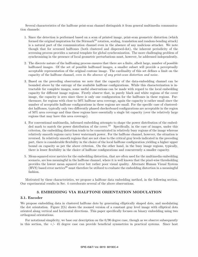
Figure 1 illustrates the data-embedding and recovery processes for a halftone printing channel. A contone originalimage I(x, y) and message data m constitute the inputs at the encoder. The halftoning and embedding processproduces a halftoned image Ih(x, y) that: (a) visually approximates the original image I(x, y), and (b) carries themessage data m. The halftoned image is printed and the decoder attempts to recover the embedded data fromthe scan of the print. In practice, in the block diagram representation of Fig. 1, the process of data embeddingmay be performed prior to, concurrently with, or after the halftoning. If the embedding is performed prior tothe halftoning, it operates on the contone image and the halftone print and scan channel appears as a rathersevere distortion that the watermark must overcome. If on the other hand, the embedding is performed after thehalftoning, it is necessary to ensure that the embedding process retains image quality which is challenging giventhat the image is already in a binarized representation. Methods that perform the embedding and the halftoningjointly are therefore typically preferable in applications where this is feasible.
m̂
(Message Data)
Scanned ImageHalftone Image
Scan
&&
Halftoning
Data-Embedding
Contone Image
Is(x, y)Ih(x, y)I(x, y)
(Estimated Data)Extraction
Data
m
Figure 1. Data embedding for the halftone print channel.
SPIE-IS&T/ Vol. 6819 68190C-3
Several characteristics of the halftone print-scan channel distinguish it from general multimedia communica-tion channels:
1. Since the detection is performed based on a scan of printed image, print-scan geometric distortion (whichformed the original inspiration for the Stirmark18 rotation, scaling, translation and random-bending attack)is a natural part of the communication channel even in the absence of any malicious attacker. We notethough that for screened halftones (both clustered and dispersed-dot), the inherent periodicity of thescreening process provides a natural template for global synchronization. The more challenging problem ofsynchronizing in the presence of local geometric perturbations must, however, be addressed independently.
2. The discrete nature of the halftoning process ensures that there are a finite, albeit large, number of possiblehalftoned images. Of the set of possible halftoned images, a smaller subset will provide a perceptuallyacceptable representation of the original contone image. The cardinality of this set defines a limit on thecapacity of the halftone channel, even in the absence of any print-scan distortion and noise.
3. Based on the preceding observation we note that the capacity of the data-embedding channel can bebounded above by the entropy of the available halftone configurations. While this characterization is in-tractable for complete images, some useful observations can be made with regard to the local embeddingcapacity for different image regions. Firstly observe that, in purely black and white regions of the coverimage, the capacity is zero since there is only one configuration for the halftones in these regions. Fur-thermore, for regions with close to 50% halftone area coverage, again the capacity is rather small since thenumber of acceptable halftone configurations in these regions are small. For the specific case of clustered-dot halftones, typically only two differently phased checkerboard configurations are acceptable in the regionof 50% area coverage and thus these regions have essentially a single bit capacity (over the relatively largeregions that may have this area coverage).
4. For conventional multimedia, informed embedding attempts to shape the power distribution of the embed-ded mark to match the power distribution of the cover.19 Specifically, in the case of images, under thiscriterion, the embedding distortion tends to be concentrated in relatively busy regions of the image whereasrelatively smooth regions carry lower watermark power. For the halftone channel, however, the situation isreversed. In relatively smooth regions that are not close to the critical gray levels indicated in the precedingpart, there is considerable flexibility in the choice of the local halftone configuration yielding a higher upperbound on capacity as per the above criterion. On the other hand, in the busy image regions, typically,there is lesser flexibility in the choice of halftone configurations and concurrently a smaller capacity.
5. Mean-squared error metrics for the embedding distortion, that are often used for the multimedia embeddingscenario, are less meaningful in the halftone channel, where it is well known that the pixel-wise thresholdingprovides the lowest mean squared error but rather poor visual quality. Alternate Human Visual System(HVS) based error metrics20 must therefore be utilized to evaluate the embedding distortion in a meaningfulfashion.
Motivated by these characteristics, we propose a halftone data embedding method, in the following section.Our experimental results in Sec. 4 corroborate several of the above observations.
3. EMBEDDING VIA HALFTONE ORIENTATION MODULATION
3.1. Encoder
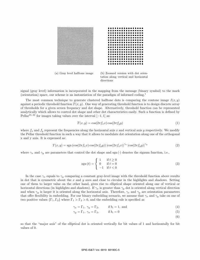
We propose embedding data in clustered halftone dots by generating elliptically shaped dots, and modulatingthe dot orientation. Figure 2(b) shows the zoomed version of a constant gray level image with elliptical dotsoriented along vertical and horizontal directions. This paper specifically focuses on binary embedding using twoorthogonal orientations.
For notational simplicity, we base our description on the 0/90 degree case, though as we observe subsequentlyin this section, the +/- 45 degree case can provide beneficial symmetries in practical systems. Since host
SPIE-IS&T/ Vol. 6819 68190C-4
1511151 155511555................................S.. IS. 11.51.....................ISIS..II.I 15551111151 155151111151S5S5S1S51 555.SS................SII.IIII 151551151S5S1S11 IS......11155155511 15511................
(a) Gray level halftone image (b) Zoomed version with dot orien-tation along vertical and horizontaldirections
signal (gray level) information is incorporated in the mapping from the message (binary symbol) to the mark(orientation) space, our scheme is an instantiation of the paradigm of informed coding.1
The most common technique to generate clustered halftone dots is comparing the contone image I(x, y)against a periodic threshold function T (x, y). One way of generating threshold function is to design discrete arrayof thresholds for a given screen frequency and dot shape. Alternatively, threshold function can be representedanalytically which allows to control dot shape and other dot characteristics easily. Such a function is defined byPellar21, 22 for images taking values over the interval [−1, 1] as:
T (x, y) = cos(2πfxx) cos(2πfyy) (1)
where fx and fy represent the frequencies along the horizontal axis x and vertical axis y respectively. We modifythe Pellar threshold function in such a way that it allows to modulate dot orientation along one of the orthogonalx and y axis. It is expressed as:
T (x, y) = sgn (cos(2πfxx) cos(2πfyy)) |cos(2πfxx)|γx |cos(2πfyy)|γy (2)
where γx and γy are parameters that control the dot shape and sgn (·) denotes the signum function, i.e.,
sgn (t) =
⎧⎨
⎩
1 if t ≥ 00 if t = 0−1 if t < 0
(3)
In the case γx equals to γy comparing a constant gray-level image with the threshold function above resultsin dot that is symmetric about the x and y axes and close to circular in the highlights and shadows. Settingone of them to larger value on the other hand, gives rise to elliptical shape oriented along one of vertical orhorizontal directions (in highlights and shadows). If γx is greater than γy dot is oriented along vertical directionand when γy is larger it is oriented along the horizontal axis. Therefore, γx and γy are orientation parametersthat offer flexibility in embedding. For our binary embedding scenario, we assume that γx and γy take on one oftwo positive values {Γ1, Γ2} where Γ1 > Γ2 > 0, and the embedding rule is specified as
γx = Γ1, γy = Γ2, if bi = 1, and (4)γy = Γ1, γx = Γ2, if bi = 0 (5)
(6)
so that the “major axis” of the elliptical dot is oriented vertically for bit values of 1 and horizontally for bitvalues of 0.
SPIE-IS&T/ Vol. 6819 68190C-5
The halftone image is then obtained as follows:
Ih(x, y) =
{1 if I(x, y) ≥ T (x, y),0 if I(x, y) < T (x, y),
(7)
For typical printing resolutions, the proposed orientation based embedding causes a minimal degradation inhalftone image quality. When the two orthogonal orientations used for the embedding are symmetrically locatedwith respect to the two orthogonal directions that define the printer addressability, the symmetry in the printingsystem ensures that the tone response for halftones of the two orientations is identical. Thus the embedding doesnot change the average gray-level, which is the fundamental image fidelity criterion in the halftone reproduction.This happens for instance when the embedding utilizes a +/- 45 degree orientation in a printing system with thenatural 0/90 degree axes. This characteristic is similar to that for GlossMarks9 that use orientation in order toencode a relatively coarse gloss pattern. Note also that in pure black or pure white regions of the cover image,the threshold function has no effect. Thus, when dictated by the cover image, our “power-law modulation” forchanging the orientation sacrifices the orientation modulation in favor of maintaining image fidelity.
3.2. DecoderAt the decoder the goal is to estimate the embedded data from a scan of printed image. Since the data isembedded in dot orientation, statistical criteria that capture orientation must be developed for data extraction.In particular, we propose moments as a statistic for detection. The moments are computed as:
σx =
∑
x,y∈C
Is(x, y)(x − x)2
∑
x,y∈C
Is(x, y)(8)
σy =
∑
x,y∈C
Is(x, y)(y − y)2
∑
x,y∈C
Is(x, y)(9)
where x =
∑
x,y∈C
Is(x, y)x
∑
x,y∈C
Is(x, y)and y =
∑
x,y∈C
Is(x, y)y
∑
x,y∈C
Is(x, y)represent the center of mass of the halftone dot. σx,
σy indicate moments along orthogonal x and y axes respectively. All pixels in the halftone cell contribute tomoments along horizontal and vertical directions according to their value Is(x, y) and distance to center of massin the horizontal or vertical direction. In essence, the moment vector σ = (σx, σy) can be interpreted as alower-dimensional (2-D) feature vector extracted from the high dimensional received signal, i.e. halftone dotthat helps identify the orientation.
The print-scan channel introduces two kinds of distortion on the halftone image: 1.) geometric distortionsdue to imperfect dot registration, and 2.) noise dependent on the input gray level. Further, geometric distortionscaused by the print-scan process comprise of both global rotation, scaling and also perturbations to local imagegeometry. In fact, the well known random being Stirmark attack was inspired by a modelling of the print-scanprocess.
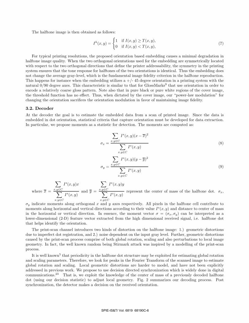
It is well known5 that periodicity in the halftone dot structure may be exploited for estimating global rotationand scaling parameters. Therefore, we look for peaks in the Fourier Transform of the scanned image to estimateglobal rotation and scaling. Local geometric distortions are harder to model, and have not been explicitlyaddressed in previous work. We propose to use decision directed synchronization which is widely done in digitalcommunications.23 That is, we exploit the knowledge of the center of mass of a previously decoded halftonedot (using our decision statistic) to adjust local geometry. Fig. 2 summarizes our decoding process. Postsynchronization, the detector makes a decision on the received orientation.
SPIE-IS&T/ Vol. 6819 68190C-6
Scanned Image
Analysis
Global Sync.
Local Sync.
&
Extraction
MomentDetector m̂
Fourier
Figure 2. Decoder
3.2.1. Hard Decoding
Since the embedding orients the “major axis” of the elliptical dots along respectively the horizontal or verticaldirections, hard decoding is performed by simply comparing the moments σx and σy estimated from the scannedimage for a given cell, i.e., the hard detection decision rule is given by
σx
1≷0
σy. (10)
3.2.2. Soft Decoding and Statistical Channel Modeling
The hard decoding criterion in the previous subsection is intuitively meaningful but does not hold any optimalityguarantees.
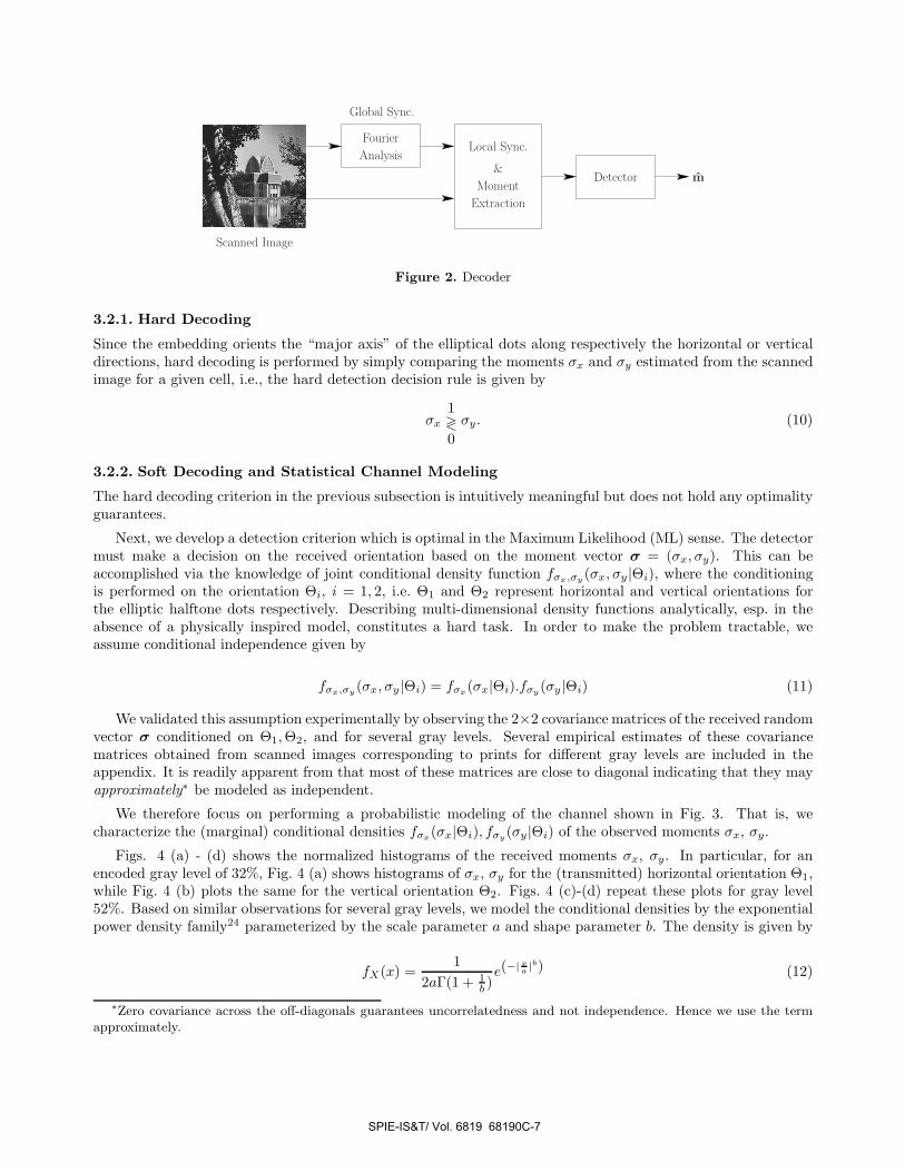
Next, we develop a detection criterion which is optimal in the Maximum Likelihood (ML) sense. The detectormust make a decision on the received orientation based on the moment vector σ = (σx, σy). This can beaccomplished via the knowledge of joint conditional density function fσx,σy (σx, σy |Θi), where the conditioningis performed on the orientation Θi, i = 1, 2, i.e. Θ1 and Θ2 represent horizontal and vertical orientations forthe elliptic halftone dots respectively. Describing multi-dimensional density functions analytically, esp. in theabsence of a physically inspired model, constitutes a hard task. In order to make the problem tractable, weassume conditional independence given by
fσx,σy (σx, σy |Θi) = fσx(σx|Θi).fσy(σy |Θi) (11)
We validated this assumption experimentally by observing the 2×2 covariance matrices of the received randomvector σ conditioned on Θ1, Θ2, and for several gray levels. Several empirical estimates of these covariancematrices obtained from scanned images corresponding to prints for different gray levels are included in theappendix. It is readily apparent from that most of these matrices are close to diagonal indicating that they mayapproximately∗ be modeled as independent.
We therefore focus on performing a probabilistic modeling of the channel shown in Fig. 3. That is, wecharacterize the (marginal) conditional densities fσx(σx|Θi), fσy(σy |Θi) of the observed moments σx, σy.
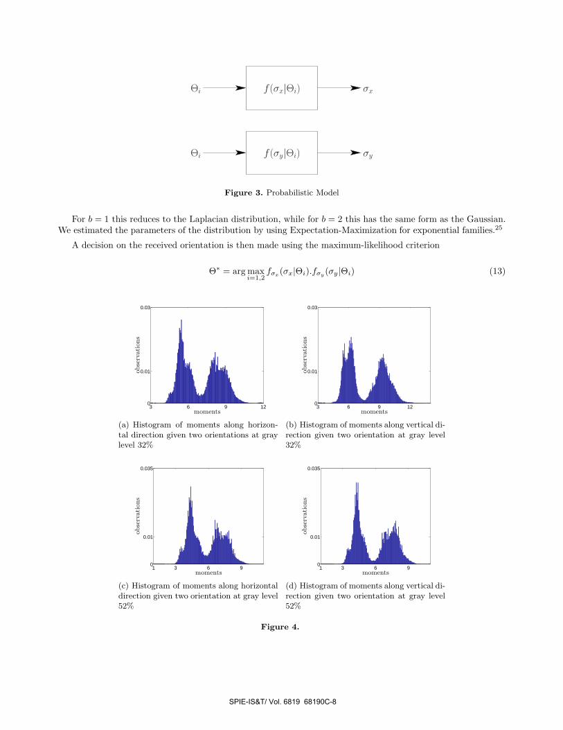
Figs. 4 (a) - (d) shows the normalized histograms of the received moments σx, σy. In particular, for anencoded gray level of 32%, Fig. 4 (a) shows histograms of σx, σy for the (transmitted) horizontal orientation Θ1,while Fig. 4 (b) plots the same for the vertical orientation Θ2. Figs. 4 (c)-(d) repeat these plots for gray level52%. Based on similar observations for several gray levels, we model the conditional densities by the exponentialpower density family24 parameterized by the scale parameter a and shape parameter b. The density is given by
fX(x) =1
2aΓ(1 + 1b )
e(−| xa |b) (12)
∗Zero covariance across the off-diagonals guarantees uncorrelatedness and not independence. Hence we use the termapproximately.
SPIE-IS&T/ Vol. 6819 68190C-7
f(σx|Θi)
f(σy|Θi)Θi σy
σxΘi
Figure 3. Probabilistic Model
For b = 1 this reduces to the Laplacian distribution, while for b = 2 this has the same form as the Gaussian.We estimated the parameters of the distribution by using Expectation-Maximization for exponential families.25
A decision on the received orientation is then made using the maximum-likelihood criterion
Θ∗ = arg maxi=1,2
fσx(σx|Θi).fσy(σy |Θi) (13)
3 6 9 120
0.01
0.03
moments
obse
rvat
ions
(a) Histogram of moments along horizon-tal direction given two orientations at graylevel 32%
3 6 9 120
0.01
0.03
moments
obse
rvat
ions
(b) Histogram of moments along vertical di-rection given two orientation at gray level32%
1 3 6 90
0.01
0.035
moments
obse
rvat
ions
(c) Histogram of moments along horizontaldirection given two orientation at gray level52%
1 3 6 90
0.01
0.035
moments
obse
rvat
ions
(d) Histogram of moments along vertical di-rection given two orientation at gray level52%
Figure 4.
SPIE-IS&T/ Vol. 6819 68190C-8
4. EXPERIMENTAL RESULTS
First, we demonstrate performance over constant gray level images. We work with a 19200×19200 constant graylevel image, and a 2400 dpi printer which means the image renders in a 8 inch by 8 inch area. We set orientationparameters γx to 1 and γy to 2 in order to achieve a horizontally oriented dot, and swap the parameters to orientthe dot in vertical direction. The halftone images are generated with a screen frequency of 75 cells per inch alongboth vertical and horizontal directions. If each halftone cell is used for embedding, this amounts to 360,000 bitsof embedding in the image.
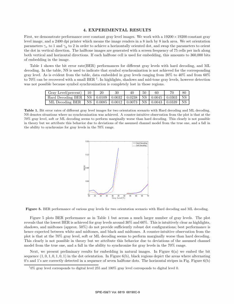
Table 1 shows the bit error rate(BER) performances for different gray levels with hard decoding, and MLdecoding. In the table, NS is used to indicate that symbol synchronization is not achieved for the correspondinggray level. As is evident from the table, data embedded in gray levels ranging from 20% to 40% and from 60%to 70% can be recovered with a small BER †. In highlights, shadows and mid-tone gray levels, however detectionwas not possible because symbol synchronization is completely lost in those regions.
Gray Level(percent) 10 20 30 40 50 60 70 80Hard Decoding BER NS 0.0109 0.0032 0.0238 NS 0.0045 0.0303 NSML Decoding BER NS 0.0085 0.0012 0.0073 NS 0.0043 0.0339 NS
Table 1. Bit error rates of different gray level images for two orientation scenario with Hard decoding and ML decoding.NS denotes situations where no synchronization was achieved. A counter-intuitive observation from the plot is that at the70% gray level, soft or ML decoding seems to perform marginally worse than hard decoding. This clearly is not possiblein theory but we attribute this behavior due to deviations of the assumed channel model from the true one, and a fall inthe ability to synchronize for gray levels in the 70% range.
20 25 30 35 40 45 50 55 60 65 700
0.04
0.08
0.12
0.16
Gray Level(%)
BE
R
Hard DecodingSoft Decoding
Figure 5. BER performance of various gray levels for two orientation scenario with Hard decoding and ML decoding.
Figure 5 plots BER performance as in Table 1 but across a much larger number of gray levels. The plotreveals that the lowest BER is achieved for gray levels around 30% and 60%. This is intuitively clear as highlights,shadows, and midtones (approx. 50%) do not provide sufficiently robust dot configurations; best performance ishence expected between white and midtones, and black and midtones. A counter-intuitive observation from theplot is that at the 70% gray level, soft or ML decoding seems to perform marginally worse than hard decoding.This clearly is not possible in theory but we attribute this behavior due to deviations of the assumed channelmodel from the true one, and a fall in the ability to synchronize for gray levels in the 70% range.
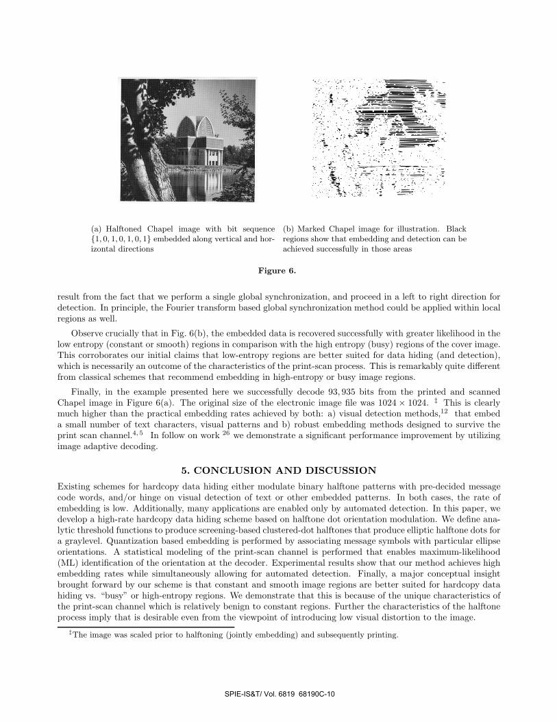
Next, we present preliminary results for embedding in natural images. In Figure 6(a) we embed the bitsequence (1, 0, 1, 0, 1, 0, 1) in the dot orientation. In Figure 6(b), black regions depict the areas where alternating0’s and 1’s are correctly detected in a sequence of seven halftone dots. The horizontal stripes in Fig. Figure 6(b)
†0% gray level corresponds to digital level 255 and 100% gray level corresponds to digital level 0.
SPIE-IS&T/ Vol. 6819 68190C-9
- :- -
(a) Halftoned Chapel image with bit sequence{1, 0, 1, 0, 1, 0, 1} embedded along vertical and hor-izontal directions
(b) Marked Chapel image for illustration. Blackregions show that embedding and detection can beachieved successfully in those areas
Figure 6.
result from the fact that we perform a single global synchronization, and proceed in a left to right direction fordetection. In principle, the Fourier transform based global synchronization method could be applied within localregions as well.
Observe crucially that in Fig. 6(b), the embedded data is recovered successfully with greater likelihood in thelow entropy (constant or smooth) regions in comparison with the high entropy (busy) regions of the cover image.This corroborates our initial claims that low-entropy regions are better suited for data hiding (and detection),which is necessarily an outcome of the characteristics of the print-scan process. This is remarkably quite differentfrom classical schemes that recommend embedding in high-entropy or busy image regions.
Finally, in the example presented here we successfully decode 93, 935 bits from the printed and scannedChapel image in Figure 6(a). The original size of the electronic image file was 1024 × 1024. ‡ This is clearlymuch higher than the practical embedding rates achieved by both: a) visual detection methods,12 that embeda small number of text characters, visual patterns and b) robust embedding methods designed to survive theprint scan channel.4, 5 In follow on work 26 we demonstrate a significant performance improvement by utilizingimage adaptive decoding.
5. CONCLUSION AND DISCUSSION
Existing schemes for hardcopy data hiding either modulate binary halftone patterns with pre-decided messagecode words, and/or hinge on visual detection of text or other embedded patterns. In both cases, the rate ofembedding is low. Additionally, many applications are enabled only by automated detection. In this paper, wedevelop a high-rate hardcopy data hiding scheme based on halftone dot orientation modulation. We define ana-lytic threshold functions to produce screening-based clustered-dot halftones that produce elliptic halftone dots fora graylevel. Quantization based embedding is performed by associating message symbols with particular ellipseorientations. A statistical modeling of the print-scan channel is performed that enables maximum-likelihood(ML) identification of the orientation at the decoder. Experimental results show that our method achieves highembedding rates while simultaneously allowing for automated detection. Finally, a major conceptual insightbrought forward by our scheme is that constant and smooth image regions are better suited for hardcopy datahiding vs. “busy” or high-entropy regions. We demonstrate that this is because of the unique characteristics ofthe print-scan channel which is relatively benign to constant regions. Further the characteristics of the halftoneprocess imply that is desirable even from the viewpoint of introducing low visual distortion to the image.
‡The image was scaled prior to halftoning (jointly embedding) and subsequently printing.
SPIE-IS&T/ Vol. 6819 68190C-10
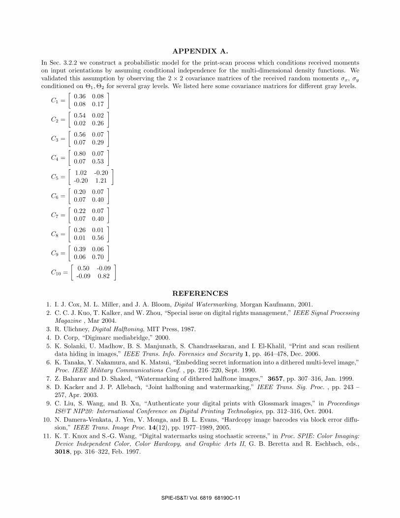
APPENDIX A.
In Sec. 3.2.2 we construct a probabilistic model for the print-scan process which conditions received momentson input orientations by assuming conditional independence for the multi-dimensional density functions. Wevalidated this assumption by observing the 2 × 2 covariance matrices of the received random moments σx, σy
conditioned on Θ1, Θ2 for several gray levels. We listed here some covariance matrices for different gray levels.
C1 =[
0.36 0.080.08 0.17
]
C2 =[
0.54 0.020.02 0.26
]
C3 =[
0.56 0.070.07 0.29
]
C4 =[
0.80 0.070.07 0.53
]
C5 =[
1.02 -0.20-0.20 1.21
]
C6 =[
0.20 0.070.07 0.40
]
C7 =[
0.22 0.070.07 0.40
]
C8 =[
0.26 0.010.01 0.56
]
C9 =[
0.39 0.060.06 0.70
]
C10 =[
0.50 -0.09-0.09 0.82
]
REFERENCES
1. I. J. Cox, M. L. Miller, and J. A. Bloom, Digital Watermarking, Morgan Kaufmann, 2001.2. C. C. J. Kuo, T. Kalker, and W. Zhou, “Special issue on digital rights management,” IEEE Signal Processing
Magazine , Mar 2004.3. R. Ulichney, Digital Halftoning, MIT Press, 1987.4. D. Corp, “Digimarc mediabridge,” 2000.5. K. Solanki, U. Madhow, B. S. Manjunath, S. Chandrasekaran, and I. El-Khalil, “Print and scan resilient
data hiding in images,” IEEE Trans. Info. Forensics and Security 1, pp. 464–478, Dec. 2006.6. K. Tanaka, Y. Nakamura, and K. Matsui, “Embedding secret information into a dithered multi-level image,”
Proc. IEEE Military Communications Conf. , pp. 216–220, Sept. 1990.7. Z. Baharav and D. Shaked, “Watermarking of dithered halftone images,” 3657, pp. 307–316, Jan. 1999.8. D. Kacker and J. P. Allebach, “Joint halftoning and watermarking,” IEEE Trans. Sig. Proc. , pp. 243 –
257, Apr. 2003.9. C. Liu, S. Wang, and B. Xu, “Authenticate your digital prints with Glossmark images,” in Proceedings
IS&T NIP20: International Conference on Digital Printing Technologies, pp. 312–316, Oct. 2004.10. N. Damera-Venkata, J. Yen, V. Monga, and B. L. Evans, “Hardcopy image barcodes via block error diffu-
sion,” IEEE Trans. Image Proc. 14(12), pp. 1977–1989, 2005.11. K. T. Knox and S.-G. Wang, “Digital watermarks using stochastic screens,” in Proc. SPIE: Color Imaging:
Device Independent Color, Color Hardcopy, and Graphic Arts II, G. B. Beretta and R. Eschbach, eds.,3018, pp. 316–322, Feb. 1997.
SPIE-IS&T/ Vol. 6819 68190C-11
12. G. Sharma and S.-G. Wang, “Show-through watermarking of duplex printed documents,” in Proc. SPIE:Security, Steganography, and Watermarking of Multimedia Contents VI, E. J. Delp and P. W. Wong, eds.,5306, Jan. 2004.
13. B. Oztan and G. Sharma, “Continuous phase modulated halftones and their application to halftone dataembedding,” in Proc. IEEE Intl. Conf. Acoustics Speech and Sig. Proc., II, pp. 333–336, May 2006.
14. S. Wang, “Digital watermarking using phase-shifted stoclustic screens.” US Pat. #6,252,971, 2001.15. M. Analoui and J. P. Allebach, “Model based halftoning using direct binary search,” Proc. SPIE Annual
Symp. on Electronic Imaging , Feb. 1992.16. D. L. Hecht, “Printed embedded data graphical user interfaces,” IEEE Computer , pp. 47–55, Mar. 2001.17. D. L. Hecht, “Embedded data glyph technology for hardcopy digital documents,” in Proc. SPIE: Color hard
copy and graphic arts III, J. Bares, ed., 2171, pp. 341–352, Feb. 1994.18. F. A. P. Petitcolas, R. J. Anderson, and M. G. Kuhn, “Attacks on copyright marking systems,” in Infor-
mation Hiding, Second International Workshop, IH’98, pp. 219–239, (Portland, OR, USA), Apr. 1998.19. J. K. Su and B. Girod, “Power-spectrum condition for energy-efficient watermarking,” IEEE Trans. Multi-
media 4(4), pp. 551–560, 2002.20. A. U. Agar, F. A. Baqai, and J. P. Allebach, “Human visual model based color halftoning,” in Digital Color
Imaging Handbook, G. Sharma, ed., CRC Press, Boca Raton, FL, 2003. Chapter 7.21. R. J. Pellar and L. D. Green, “Electronic halftone generator.” United States Patent No. 4149183, 1979.22. R. J. Pellar, “Electronic halftone generator.” United States Patent No. 4196451, 1980.23. J. Proakis, Digital Communications, McGraw-Hill, New York, fourth ed., 2001.24. H. Stark and J. W. Woods, Probability, Random Processes and Estimation Theory for Engineers, Prentice-
Hall, Englewood Cliffs, NJ, 1986.25. J. Salojarvi and K. Puolamaki, “Expectation maximization algorithms for conditional likelihoods,” Proc.
22nd International Conference on Machine Learning , Aug. 2005.26. O. Bulan, G.Sharma, and V. Monga, “Image adaptive decoding for halftone orientation based data hiding,”
To be submitted to ICIP 2008.
SPIE-IS&T/ Vol. 6819 68190C-12