Embed Size (px)
Citation preview

Data CommunicationsNetwork Models

1. Layered Task We use the concept of layers in our
daily life. As an example, let us consider two friends who communicate through postal mail. The process of sending a letter to a friend would be complex if there were no services available from the post office.

Tasks involved in sending a letter•http://webmuseum.mi.fh-offenburg.de/ind
ex.php?view=exh&src=42
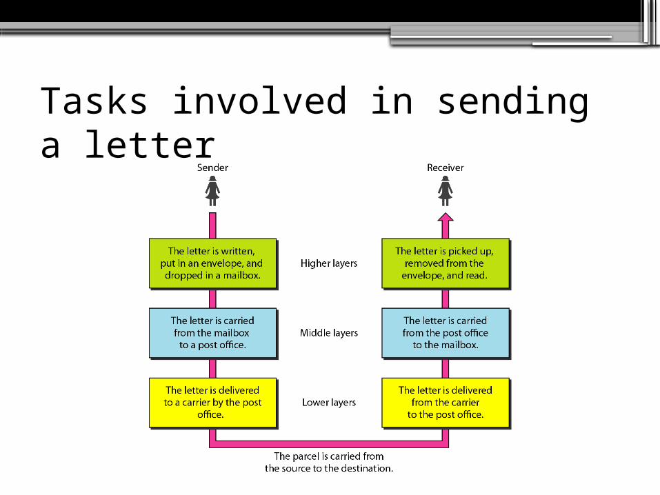
Tasks involved in sending a letter

2. The OSI ModelEstablished in 1947, the International
Standards Organization (ISO) is a multinational body dedicated to worldwide agreement on international standards. An ISO standard that covers all aspects of network communications is the Open Systems Interconnection (OSI) model. It was first introduced in the late 1970s.

ISO is the organization.OSI is the model.

Seven layers of the OSI model

The interaction between layers in the OSI model

An exchange using the OSI modelhttp://webmuseum.mi.fh-offenburg.de/index.php?view=exh&src=15

An exchange using the OSI model

Encapsulation
In other words, the data portion of a packet at level N - 1 carries the whole packet (data and header and maybe trailer) from level N. The concept is called encapsulation.Level N - 1 is not aware of which part of the encapsulated packet is data and which part is the header or trailer. For level N - 1, the whole packet coming from level N is treated as one integral unit.

Encapsulation
•http://webmuseum.mi.fh-offenburg.de/index.php?view=exh&src=77

3. Layers in the OSI ModelThe description of the functions of each layer in the OSI model.

Physical layer

Physical Layers
The physical layer is responsible for movements ofindividual bits from one hop (node) to the next.
Physical layer
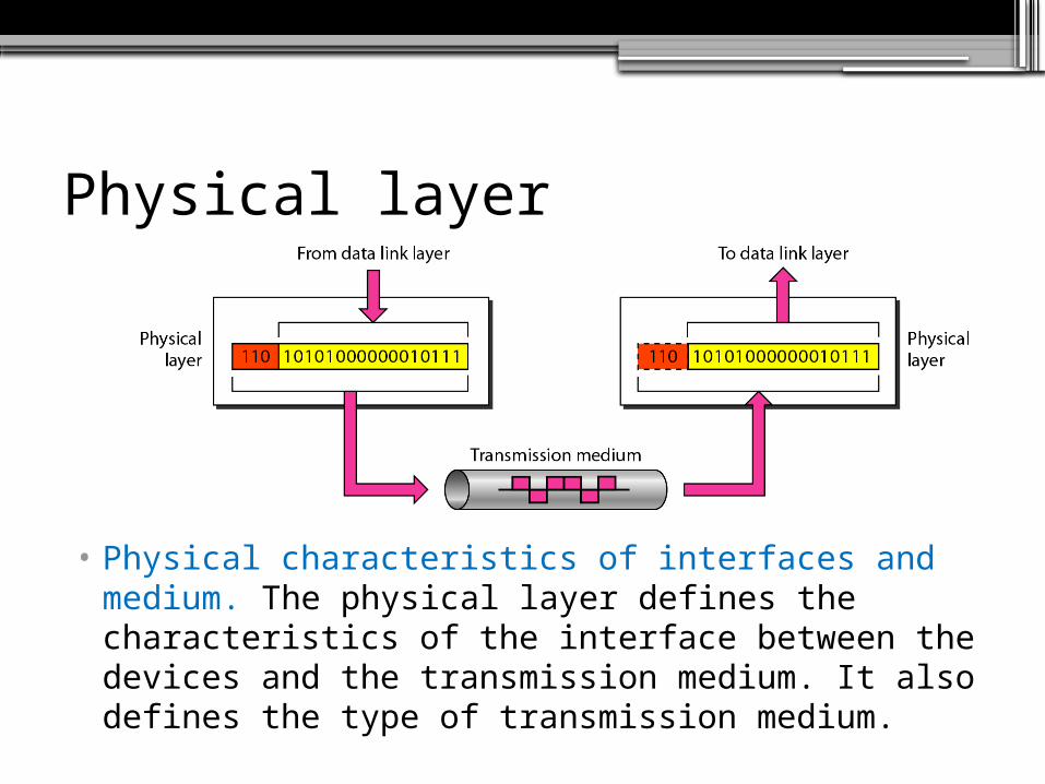
• Physical characteristics of interfaces and medium. The physical layer defines the characteristics of the interface between the devices and the transmission medium. It also defines the type of transmission medium.

Physical layer
• Representation of bits. The physical layer data consists of a stream of bits (sequence of Os or 1s) with no interpretation. To be transmitted, bits must be encoded into signals--electrical or optical. The physical layer defines the type of encoding (how Os and I s are changed to signals).
Physical layer
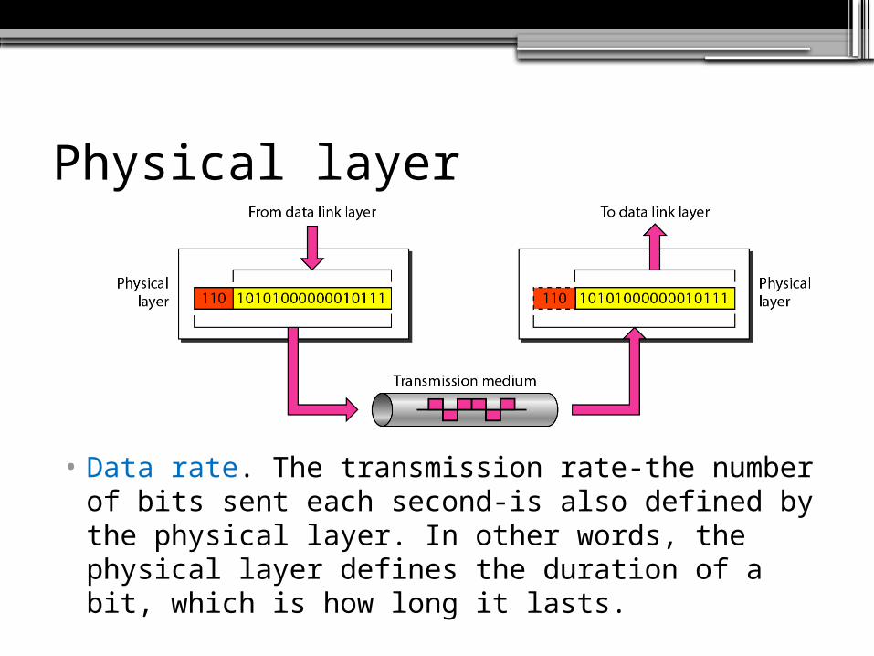
• Data rate. The transmission rate-the number of bits sent each second-is also defined by the physical layer. In other words, the physical layer defines the duration of a bit, which is how long it lasts.

Physical layer
• Synchronization of bits. The sender and receiver not only must use the same bit rate but also must be synchronized at the bit level. In other words, the sender and the receiver clocks must be synchronized.

Physical layer
• Line configuration. The physical layer is concerned with the connection of devices to the media. In a point-to-point configuration, two devices are connected through a dedicated link. In a multipoint configuration, a link is shared among several devices.

Physical layer
• Physical topology. The physical topology defines how devices are connected to make a network.

Physical layer
• Transmission mode. The physical layer also defines the direction of transmission between two devices: simplex, half-duplex, or full-duplex.
Data Link Layer
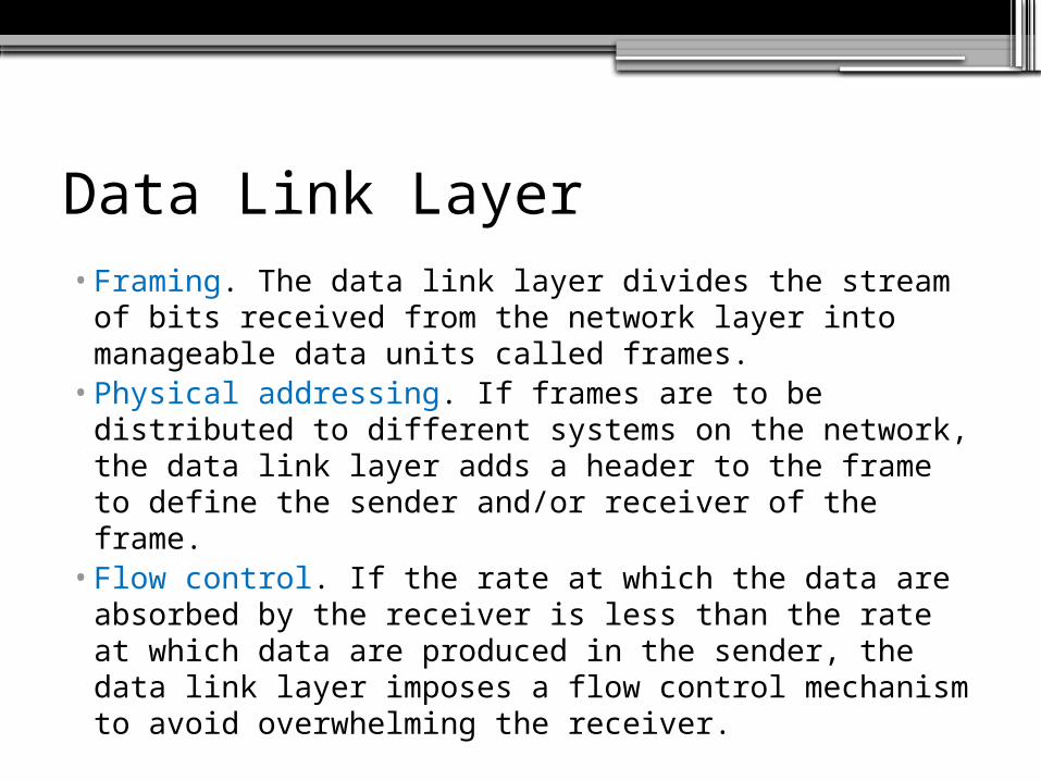
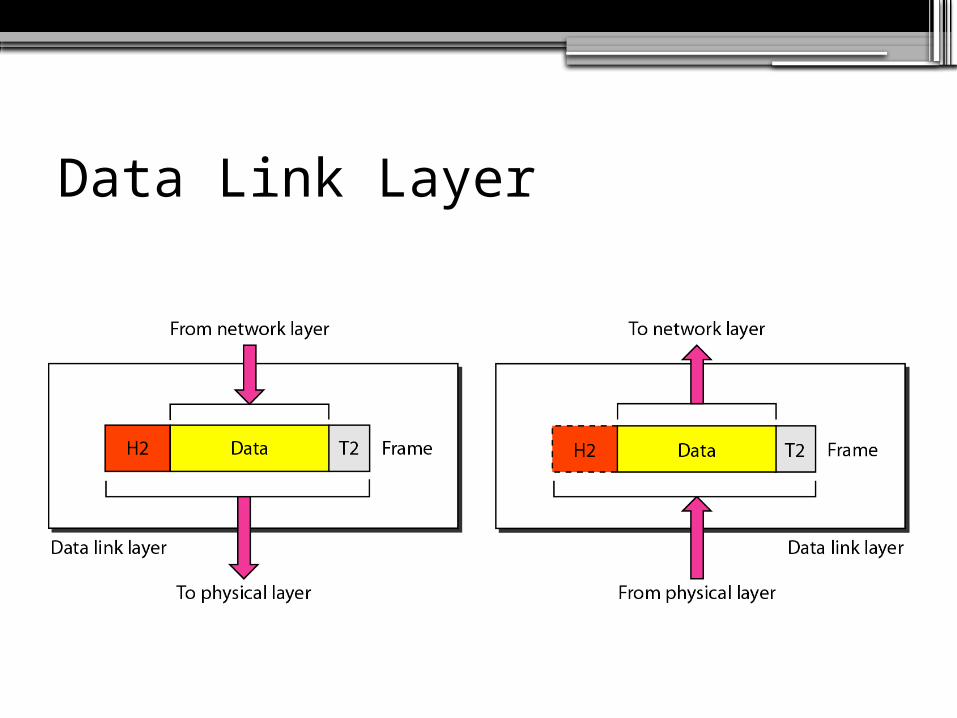
Data Link Layer• Framing. The data link layer divides the stream of
bits received from the network layer into manageable data units called frames.
• Physical addressing. If frames are to be distributed to different systems on the network, the data link layer adds a header to the frame to define the sender and/or receiver of the frame.
• Flow control. If the rate at which the data are absorbed by the receiver is less than the rate at which data are produced in the sender, the data link layer imposes a flow control mechanism to avoid overwhelming the receiver.

Data Link Layer• Error control. The data link layer adds reliability
to the physical layer by adding mechanisms to detect and retransmit damaged or lost frames. It also uses a mechanism to recognize duplicate frames. Error control is normally achieved through a trailer added to the end of the frame.
• Access control. When two or more devices are connected to the same link, data link layer protocols are necessary to determine which device has control over the link at any given time.

Data Link Layer
The data link layer is responsible for moving frames from one hop (node) to the next.

Data Link Layer (Hop–to–hop delivery)

Network Layer

Network Layer•Logical addressing. The physical addressing
implemented by the data link layer handles the addressing problem locally. If a packet passes the network boundary, we need another addressing system to help distinguish the source and destination systems. The network layer adds a header to the packet coming from the upper layer that, among other things, includes the logical addresses of the sender and receiver.

Network Layer
•Routing. When independent networks or links are connected to create intemetworks (network of networks) or a large network, the connecting devices (called routers or switches) route or switch the packets to their final destination. One of the functions of the network layer is to provide this mechanism.

Network Layer
The network layer is responsible for the delivery of individual packets from
the source host to the destination host.

Network Layer (Source to Destination Delivery)

Transport Layer• The transport layer is responsible for process-to-
process delivery of the entire message.• A process is an application program running on a
host. Whereas the network layer oversees source-to-destination delivery of individual packets, it does not recognize any relationship between those packets. It treats each one independently, as though each piece belonged to a separate message, whether or not it does.
• The transport layer, on the other hand, ensures that the whole message arrives intact and in order, overseeing both error control and flow control at the source-to-destination level.

Transport Layer

Transport Layer
The transport layer is responsible for the delivery of a message from one process to another.

Transport Layer• Service-point addressing. Computers often run
several programs at the same time. For this reason, source-to-destination delivery means delivery not only from one computer to the next but also from a specific process (running program) on one computer to a specific process (running program) on the other. The transport layer header must therefore include a type of address called a service-point address (or port address). The network layer gets each packet to the correct computer; the transport layer gets the entire message to the correct process on that computer.

Transport Layer
•Segmentation and reassembly. A message is divided into transmittable segments, with each segment containing a sequence number. These numbers enable the transport layer to reassemble the message correctly upon arriving at the destination and to identify and replace packets that were lost in transmission.

Transport Layer• Connection control. The transport layer can be
either connectionless or connectionoriented. A connectionless transport layer treats each segment as an independent packet and delivers it to the transport layer at the destination machine. A connection oriented transport layer makes a connection with the transport layer at the destination machine first before delivering the packets. After all the data are transferred, the connection is terminated.
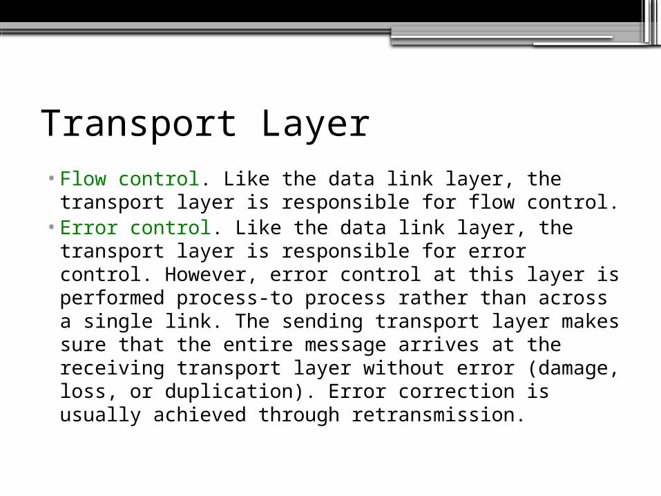
Transport Layer• Flow control. Like the data link layer, the
transport layer is responsible for flow control.• Error control. Like the data link layer, the
transport layer is responsible for error control. However, error control at this layer is performed process-to process rather than across a single link. The sending transport layer makes sure that the entire message arrives at the receiving transport layer without error (damage, loss, or duplication). Error correction is usually achieved through retransmission.

Transport Layer (Reliable process-to-process delivery of a message)

Session Layer
•The session layer is the network dialog controller.
•It establishes, maintains, and synchronizes the interaction among communicating systems.
The session layer is responsible for dialog control and synchronization.

Session Layer

Session Layer
•Dialog control. The session layer allows two systems to enter into a dialog. It allows the communication between two processes to take place in either halfduplex (one way at a time) or full-duplex (two ways at a time) mode.
•Synchronization. The session layer allows a process to add checkpoints, or synchronization points, to a stream of data.

Presentation Layer
•The presentation layer is concerned with the syntax and semantics of the information exchanged between two systems.

Presentation Layer
•Translation. The processes (running programs) in two systems are usually exchanging information in the form of character strings, numbers, and so on. The information must be changed to bit streams before being transmitted. Because different computers use different encoding systems, the presentation layer is responsible for interoperability between these different encoding methods.

Presentation Layer
•Encryption. To carry sensitive information, a system must be able to ensure privacy. Encryption means that the sender transforms the original information to another form and sends the resulting message out over the network. Decryption reverses the original process to transform the message back to its original form.

Presentation Layer
•Compression. Data compression reduces the number of bits contained in the information. Data compression becomes particularly important in the transmission of multimedia such as text, audio, and video.

Presentation Layer

Presentation Layer
The presentation layer is responsible for translation, compression, and encryption.
Application Layer
•The application layer enables the user, whether human or software, to access the network.
•It provides user interfaces and support for services such as electronic mail, remote file access and transfer, shared database management, and other types of distributed information services.
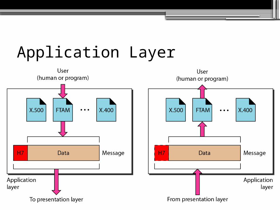
Application Layer

Application Layer
The application layer is responsible for providing services to the user.

Application Layer• File transfer, access, and management. This
application allows a user to access files in a remote host (to make changes or read data), to retrieve files from a remote computer for use in the local computer, and to manage or control files in a remote computer locally.
• Mail services. This application provides the basis for e-mail forwarding and storage.
• Directory services. This application provides distributed database sources and access for global information about various objects and services.

Summary of Layers

TCP/IP PROTOCOL

TCP/IP Protocol SuiteThe layers in the TCP/IP protocol suite do not exactly match those in the OSI model. The original TCP/IP protocol suite was defined as having four layers: host-to-network, internet, transport, and application. However, when TCP/IP is compared to OSI, we can say that the TCP/IP protocol suite is made of five layers: physical, data link, network, transport, and application.

Seven layers of the OSI model

Physical and Data Link Layers

Internetworking Protocol (IP)

Transport Layer


TCP/IP and OSI Model

Addressing
Four levels of addresses are used in an internet employing the TCP/IP protocols: physical, logical, port, and specific.

Address in TCP/IP

Relationship of layers and addresses in TCP/IP

Physical Addresses (Example 1)

Physical Addresses (Example 2)
Most local-area networks use a 48-bit (6-byte) physical address written as 12 hexadecimal digits; every byte (2 hexadecimal digits) is separated by a colon, as shown below:
07:01:02:01:2C:4B
A 6-byte (12 hexadecimal digits) physical address.

Physical Addresses (Example 3 – IP Addresses)

Physical Addresses (Example 4 – Port Addresses)

The physical addresses will change from hop to hop,
but the logical addresses usually remain the same.

Physical Addresses (Example 5)
A port address is a 16-bit address represented by one decimal number as shown.
753
A 16-bit port address represented as one single number.
The physical addresses will change from hop to hop,
but the logical addresses usually remain the same.

Exercises