Embed Size (px)
Citation preview
VersaPOD® Data Center Cabinets
WWW.SIEMON.COM
BRC_VPOD_US_REV_J.qxp_J 12/15/16 4:33 PM Page 2
1
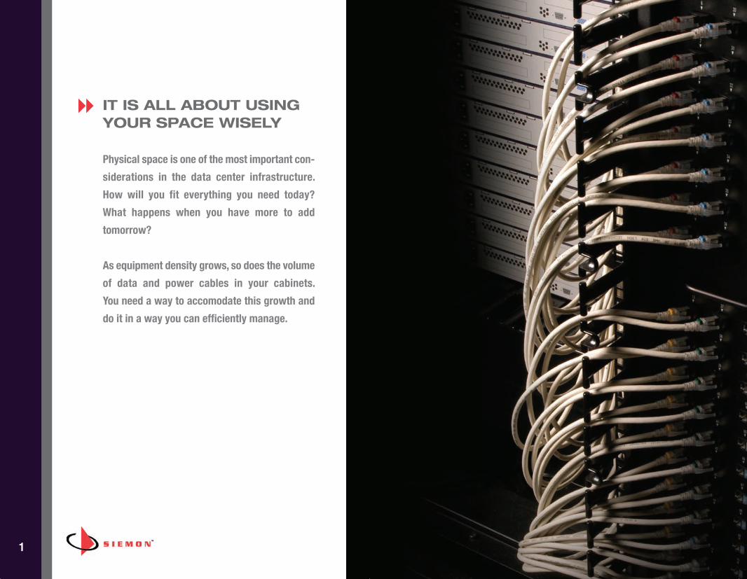
IT IS ALL ABOUT USINGYOUR SPACE WISELY
Physical space is one of the most important con-
siderations in the data center infrastructure.
How will you fit everything you need today?
What happens when you have more to add
tomorrow?
As equipment density grows, so does the volume
of data and power cables in your cabinets.
You need a way to accomodate this growth and
do it in a way you can efficiently manage.
8
BRC_VPOD_US_REV_J.qxp_J 12/15/16 4:33 PM Page 3
2
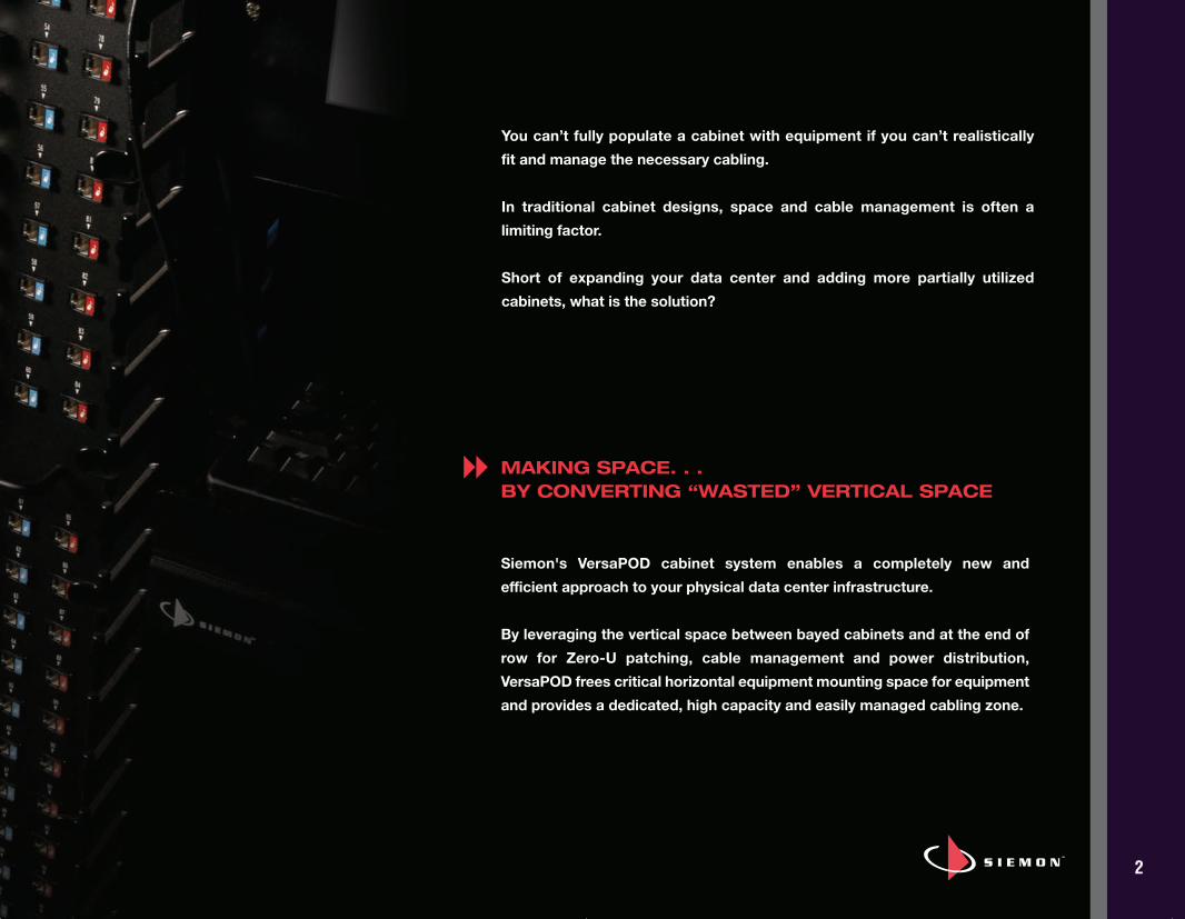
You can’t fully populate a cabinet with equipment if you can’t realistically fit and manage the necessary cabling.
In traditional cabinet designs, space and cable management is often a limiting factor.
Short of expanding your data center and adding more partially utilized cabinets, what is the solution?
MAKING SPACE. . .BY CONVERTING “WASTED” VERTICAL SPACE
Siemon's VersaPOD cabinet system enables a completely new and efficient approach to your physical data center infrastructure.
By leveraging the vertical space between bayed cabinets and at the end ofrow for Zero-U patching, cable management and power distribution, VersaPOD frees critical horizontal equipment mounting space for equipmentand provides a dedicated, high capacity and easily managed cabling zone.
8
BRC_VPOD_US_REV_J.qxp_J 12/15/16 4:33 PM Page 4
3
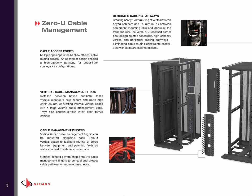
Zero-U CableManagement
VERTICAL CABLE MANAGEMENT TRAYSInstalled between bayed cabinets, these vertical managers help secure and route highcable-counts, converting internal vertical spaceinto a large-volume cable management zone. Trays also contain airflow within each bayed cabinet.
CABLE MANAGEMENT FINGERSVertical 6-inch cable management fingers canbe mounted alongside each Zero-U vertical space to facilitate routing of cords between equipment and patching fields aswell as cabinet to cabinet connections.
Optional hinged covers snap onto the cablemanagement fingers to conceal and protectcable pathway for improved aesthetics.
CABLE ACCESS POINTSMultiple openings in the lid allow efficient cablerouting access. An open floor design enablesa high-capacity pathway for under-floor conveyance configurations.
DEDICATED CABLING PATHWAYSCreating nearly 178mm (7 in.) of width betweenbayed cabinets and 150mm (6 in.) betweenequipment mounting rails and doors at thefront and rear, the VersaPOD recessed cornerpost design creates accessible, high-capacityvertical and horizontal cabling pathways –eliminating cable routing constraints associ-ated with standard cabinet designs.
8
BRC_VPOD_US_REV_J.qxp_J 12/15/16 4:33 PM Page 5
4
Zero-U Cable Management Benefits
Getting cable out of the cabinet’s heavily congested equipment mounting space and into high-capacity verticalcabling zones drives benefits across your data center infrastructure.
DENSITY - VersaPOD’s extra vertical space gives you theroom to deploy ultra high-density data center infrastruc-tures without sacrificing proper cable management andthe overall neatness and aesthetics of the facility.
SCALABILITY - The high capacity of VersaPOD’s Zero-U cable management zones not only leave significantspace to add cabling channels as your needs grow, it freesspace needed to mount future networking equipment with-out the need to add more cabinets and consume valuabledata center floor space.
FLEXIBILITY - VersaPOD’s wide variety of cable routingoptions enable it to support nearly any data center config-uration, giving you the flexibility to design an infrastructureto fit your needs instead of working around the space lim-itations of traditional cabinets.
ACCESSIBILITY - With your cabling channels in their owndedicated space between the cabinets, you can performongoing moves adds and changes and gain unobstructedaccess to your equipment - less time in the cabinets andmore on your strategic goals.
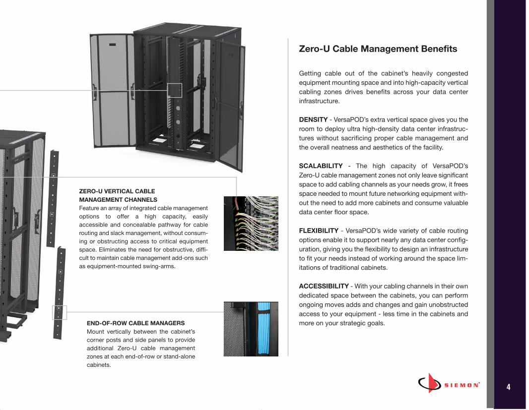
ZERO-U VERTICAL CABLE MANAGEMENT CHANNELSFeature an array of integrated cable managementoptions to offer a high capacity, easily accessible and concealable pathway for cable routing and slack management, without consum-ing or obstructing access to critical equipmentspace. Eliminates the need for obstructive, diffi-cult to maintain cable management add-ons suchas equipment-mounted swing-arms.
END-OF-ROW CABLE MANAGERSMount vertically between the cabinet’scorner posts and side panels to provideadditional Zero-U cable managementzones at each end-of-row or stand-alonecabinets.
BRC_VPOD_US_REV_J.qxp_J 12/15/16 4:34 PM Page 6
5
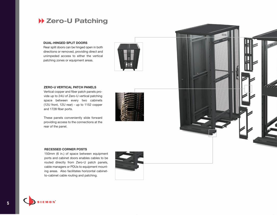
Zero-U Patching
DUAL-HINGED SPLIT DOORSRear split doors can be hinged open in bothdirections or removed, providing direct andunimpeded access to either the verticalpatching zones or equipment areas.
RECESSED CORNER POSTS150mm (6 in.) of space between equipmentports and cabinet doors enables cables to berouted directly from Zero-U patch panels,cable managers or PDUs to equipment mount-ing areas. Also facilitates horizontal cabinet-to-cabinet cable routing and patching.
8
ZERO-U VERTICAL PATCH PANELSVertical copper and fiber patch panels pro-vide up to 24U of Zero-U vertical patchingspace between every two cabinets (12U front, 12U rear) - up to 1152 copperand 1728 fiber ports.
These panels conveniently slide forwardproviding access to the connections at therear of the panel.
BRC_VPOD_US_REV_J.qxp_J 12/15/16 4:34 PM Page 7
6
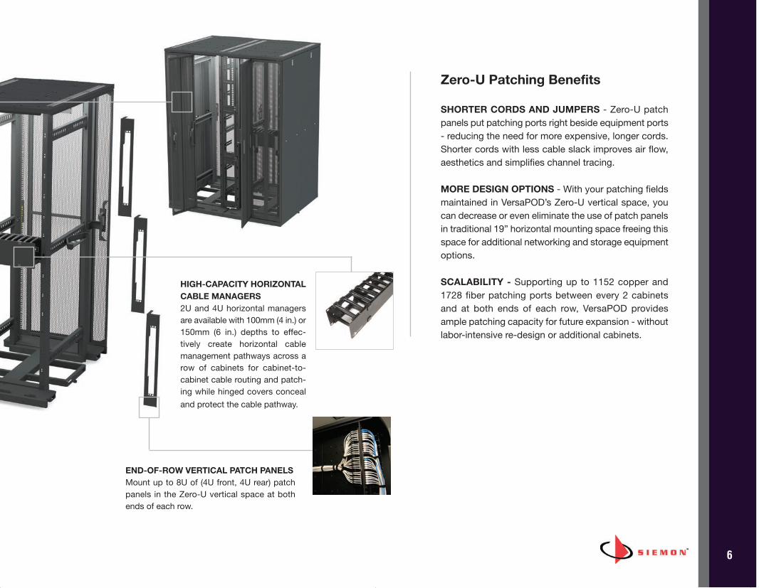
HIGH-CAPACITY HORIZONTALCABLE MANAGERS2U and 4U horizontal managersare available with 100mm (4 in.) or150mm (6 in.) depths to effec-tively create horizontal cablemanagement pathways across arow of cabinets for cabinet-to-cabinet cable routing and patch-ing while hinged covers concealand protect the cable pathway.
END-OF-ROW VERTICAL PATCH PANELSMount up to 8U of (4U front, 4U rear) patchpanels in the Zero-U vertical space at bothends of each row.
Zero-U Patching Benefits
SHORTER CORDS AND JUMPERS - Zero-U patchpanels put patching ports right beside equipment ports- reducing the need for more expensive, longer cords.Shorter cords with less cable slack improves air flow,aesthetics and simplifies channel tracing.
MORE DESIGN OPTIONS - With your patching fieldsmaintained in VersaPOD’s Zero-U vertical space, youcan decrease or even eliminate the use of patch panelsin traditional 19” horizontal mounting space freeing thisspace for additional networking and storage equipmentoptions.
SCALABILITY - Supporting up to 1152 copper and1728 fiber patching ports between every 2 cabinetsand at both ends of each row, VersaPOD providesample patching capacity for future expansion - withoutlabor-intensive re-design or additional cabinets.
BRC_VPOD_US_REV_J.qxp_J 12/15/16 4:34 PM Page 8
7
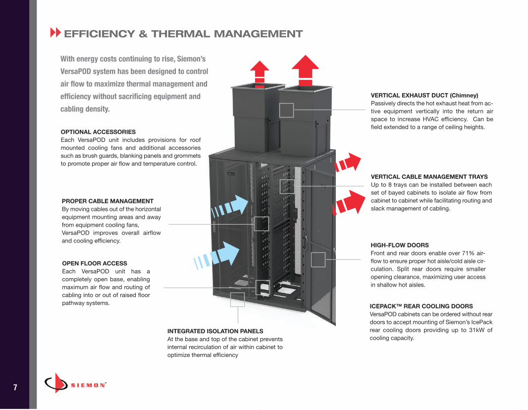
With energy costs continuing to rise, Siemon’s
VersaPOD system has been designed to control
air flow to maximize thermal management and
efficiency without sacrificing equipment and
cabling density.
EFFICIENCY & THERMAL MANAGEMENT
VERTICAL EXHAUST DUCT (Chimney)Passively directs the hot exhaust heat from ac-tive equipment vertically into the return airspace to increase HVAC efficiency. Can befield extended to a range of ceiling heights.
PROPER CABLE MANAGEMENTBy moving cables out of the horizontalequipment mounting areas and awayfrom equipment cooling fans,VersaPOD improves overall airflowand cooling efficiency.
VERTICAL CABLE MANAGEMENT TRAYSUp to 8 trays can be installed between eachset of bayed cabinets to isolate air flow fromcabinet to cabinet while facilitating routing andslack management of cabling.
HIGH-FLOW DOORSFront and rear doors enable over 71% air-flow to ensure proper hot aisle/cold aisle cir-culation. Split rear doors require smalleropening clearance, maximizing user accessin shallow hot aisles.
OPEN FLOOR ACCESSEach VersaPOD unit has a completely open base, enablingmaximum air flow and routing ofcabling into or out of raised floorpathway systems.
OPTIONAL ACCESSORIESEach VersaPOD unit includes provisions for roofmounted cooling fans and additional accessoriessuch as brush guards, blanking panels and grommetsto promote proper air flow and temperature control.
ICEPACK™ REAR COOLING DOORSVersaPOD cabinets can be ordered without reardoors to accept mounting of Siemon’s IcePackrear cooling doors providing up to 31kW ofcooling capacity.
8
INTEGRATED ISOLATION PANELS At the base and top of the cabinet preventsinternal recirculation of air within cabinet tooptimize thermal efficiency
BRC_VPOD_US_REV_J.qxp_J 12/15/16 4:34 PM Page 9
8
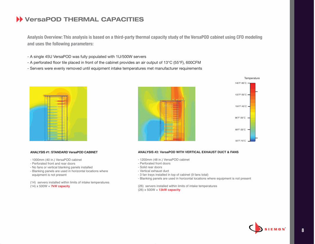
VersaPOD THERMAL CAPACITIES
Analysis Overview: This analysis is based on a third-party thermal capacity study of the VersaPOD cabinet using CFD modelingand uses the following parameters:
- A single 45U VersaPOD was fully populated with 1U/500W servers - A perforated floor tile placed in front of the cabinet provides an air output of 13°C (55°F), 600CFM- Servers were evenly removed until equipment intake temperatures met manufacturer requirements
ANALYSIS #1: STANDARD VersaPOD CABINET
- 1000mm (40 in.) VersaPOD cabinet - Perforated front and rear doors- No fans or vertical blanking panels installed- Blanking panels are used in horizontal locations where
equipment is not present
(14) servers installed within limits of intake temperatures(14) x 500W = 7kW capacity
ANALYSIS #2: VersaPOD WITH VERTICAL EXHAUST DUCT & FANS
- 1200mm (48 in.) VersaPOD cabinet - Perforated front doors- Solid rear doors- Vertical exhaust duct- 3 fan trays installed in top of cabinet (9 fans total)- Blanking panels are used in horizontal locations where equipment is not present
(26) servers installed within limits of intake temperatures(26) x 500W = 13kW capacity
8
Temperature140˚F /60˚C
122˚F /50˚C
104˚F /40˚C
86˚F /30˚C
68˚F /20˚C
50˚F /10˚C
BRC_VPOD_US_REV_J.qxp_J 12/15/16 4:34 PM Page 10
9
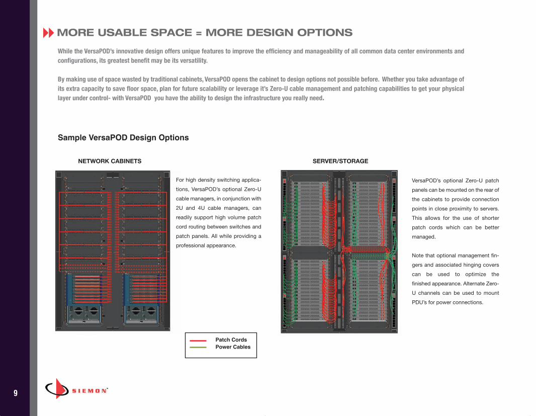
MORE USABLE SPACE = MORE DESIGN OPTIONS
While the VersaPOD’s innovative design offers unique features to improve the efficiency and manageability of all common data center environments andconfigurations, its greatest benefit may be its versatility.
By making use of space wasted by traditional cabinets, VersaPOD opens the cabinet to design options not possible before. Whether you take advantage ofits extra capacity to save floor space, plan for future scalability or leverage it’s Zero-U cable management and patching capabilities to get your physicallayer under control- with VersaPOD you have the ability to design the infrastructure you really need.
Sample VersaPOD Design Options
8
For high density switching applica-tions, VersaPOD’s optional Zero-Ucable managers, in conjunction with2U and 4U cable managers, canreadily support high volume patchcord routing between switches andpatch panels. All while providing aprofessional appearance.
VersaPOD’s optional Zero-U patchpanels can be mounted on the rear ofthe cabinets to provide connectionpoints in close proximity to servers.This allows for the use of shorterpatch cords which can be bettermanaged.
Note that optional management fin-gers and associated hinging coverscan be used to optimize the finished appearance. Alternate Zero-U channels can be used to mountPDU’s for power connections.
NETWORK CABINETS SERVER/STORAGE
Patch Cords
Power Cables
BRC_VPOD_US_REV_J.qxp_J 12/15/16 4:34 PM Page 11
10
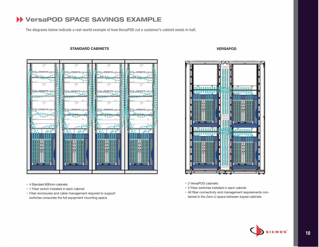
• 2 VersaPOD cabinets• 2 Fiber switches installed in each cabinet• All fiber connectivity and management requirements con-
tained in the Zero-U space between bayed cabinets
• 4 Standard 600mm cabinets• 1 Fiber switch installed in each cabinet• Fiber enclosures and cable management required to support
switches consumes the full equipment mounting space
VersaPOD SPACE SAVINGS EXAMPLE
The diagrams below indicate a real-world example of how VersaPOD cut a customer’s cabinet needs in half.
8
STANDARD CABINETS VERSAPOD
BRC_VPOD_US_REV_J.qxp_J 12/15/16 4:34 PM Page 12
11
Siemon's 42U SidePOD and Baffle solution is designed to support side-to-side ventilated active equipment such as the Cisco Nexus®
7018 Series Switches.
The SidePOD is an option for use with Siemon’s VP2A 1200mm (48 in.) deep VersaPOD cabinets and creates the necessary clearancefor proper airflow to the switch. The baffles are used to properly route cold air from the front of the cabinet to the input side of theswitch as well as route exhaust from the output side of the switch to be vented in the hot aisle. Cisco Nexus® 7018 OperationalCompliance has been validated via Computational Fluid Dynamics (CFD) modeling under maximum operating conditions
In addition to providing a cooling platform, the SidePOD also allows full size Zero-U panels to be used in End of Row applications.This includes up to 12U of vertical patching and high capacity vertical cable management with hinged covers.
END OF ROW CAPACITY Increases with SidePOD sofull size Zero-U patch panelsand cable managers can beused
INTEGRATED BRUSH GAURDS
Multiple integrated brush guardsprovide cable access to the Zero-Uspace from overhead distributionsystems
SHARED USE OF SIDE PANELS The SidePOD is compatible with VP2 side panels allowingVersaPOD panels to betransitioned to the SidePODwhen added to end of rowinstallations
REVERSIBLE BAFFLE DESIGNBaffles can be installed in eitherorientation to properly route eithercold air input or hot air exhaust.Two angled baffles may be nested180º to each other in the sameZero-U space allowing two side-vented switches to be mountednext to each other
SIDEPOD™ AND BAFFLE8
SidePOD – with two vented doorsadds 140mm (5.5 in.) width tothe end of row
ZERO U MODULARITYEnsures that with a baffle installed,the balance of Zero-U space can befully utilized for patching or cablemanagement
BRC_VPOD_US_REV_J.qxp_J 12/15/16 4:34 PM Page 13
12
MORE FEATURES & BENEFITS
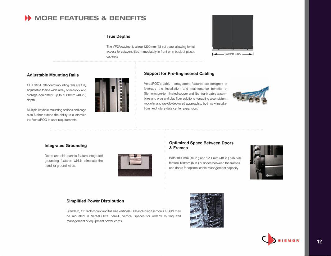
True Depths
The VP2A cabinet is a true 1200mm (48 in.) deep, allowing for fullaccess to adjacent tiles immediately in front or in back of placedcabinets
Adjustable Mounting Rails
CEA 310-E Standard mounting rails are fullyadjustable to fit a wide array of network andstorage equipment up to 1000mm (40 in.)depth.
Multiple keyhole mounting options and cagenuts further extend the ability to customizethe VersaPOD to user requirements.
Support for Pre-Engineered Cabling
VersaPOD’s cable management features are designed toleverage the installation and maintenance benefits ofSiemon’s pre-terminated copper and fiber trunk cable assem-blies and plug and play fiber solutions - enabling a consistent,modular and rapidly-deployed approach to both new installa-tions and future data center expansion.
Optimized Space Between Doors & Frames
Both 1000mm (40 in.) and 1200mm (48 in.) cabinetsfeature 150mm (6 in.) of space between the framesand doors for optimal cable management capacity.
Simplified Power Distribution
Standard, 19” rack-mount and full size vertical PDUs including Siemon’s iPDU’s maybe mounted in VersaPOD’s Zero-U vertical spaces for orderly routing and management of equipment power cords.
8
Integrated Grounding
Doors and side panels feature integratedgrounding features which eliminate theneed for ground wires.
1200 mm (48 in.)
BRC_VPOD_US_REV_J.qxp_J 12/15/16 4:34 PM Page 14
13
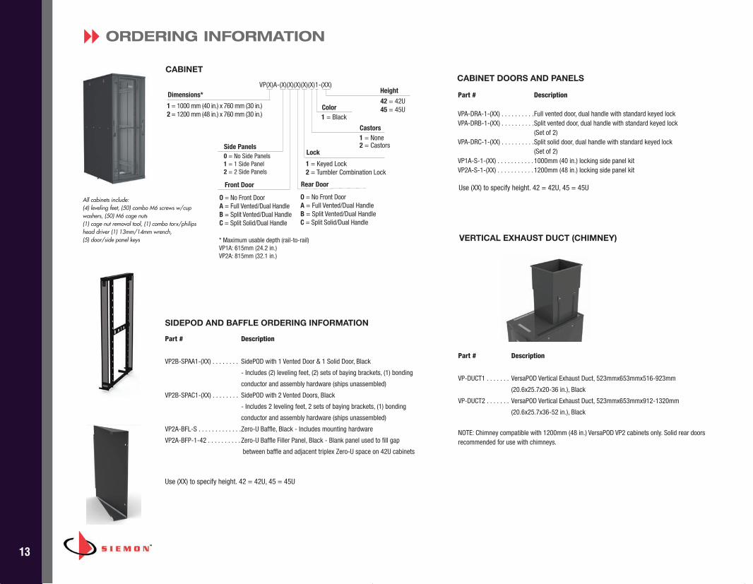
Part # Description
VPA-DRA-1-(XX) . . . . . . . . . .Full vented door, dual handle with standard keyed lockVPA-DRB-1-(XX) . . . . . . . . . .Split vented door, dual handle with standard keyed lock
(Set of 2)VPA-DRC-1-(XX) . . . . . . . . . .Split solid door, dual handle with standard keyed lock
(Set of 2)VP1A-S-1-(XX) . . . . . . . . . . . 1000mm (40 in.) locking side panel kitVP2A-S-1-(XX) . . . . . . . . . . . 1200mm (48 in.) locking side panel kit
CABINET DOORS AND PANELS
ORDERING INFORMATION
CABINET
Side Panels0 = No Side Panels1 = 1 Side Panel2 = 2 Side Panels
Front Door
O = No Front DoorA = Full Vented/Dual HandleB = Split Vented/Dual HandleC = Split Solid/Dual Handle
Rear Door
O = No Front DoorA = Full Vented/Dual HandleB = Split Vented/Dual HandleC = Split Solid/Dual Handle
Lock
1 = Keyed Lock2 = Tumbler Combination Lock
1 = 1000 mm (40 in.) x 760 mm (30 in.)2 = 1200 mm (48 in.) x 760 mm (30 in.)
Dimensions*
8
Part # Description
VP-DUCT1 . . . . . . . VersaPOD Vertical Exhaust Duct, 523mmx653mmx516-923mm
(20.6x25.7x20-36 in.), Black
VP-DUCT2 . . . . . . . VersaPOD Vertical Exhaust Duct, 523mmx653mmx912-1320mm
(20.6x25.7x36-52 in.), Black
NOTE: Chimney compatible with 1200mm (48 in.) VersaPOD VP2 cabinets only. Solid rear doorsrecommended for use with chimneys.
VERTICAL EXHAUST DUCT (CHIMNEY)
Height
42 = 42U45 = 45UColor
1 = Black
Castors1 = None2 = Castors
Use (XX) to specify height. 42 = 42U, 45 = 45U
SIDEPOD AND BAFFLE ORDERING INFORMATION
Use (XX) to specify height. 42 = 42U, 45 = 45U
Part # Description
VP2B-SPAA1-(XX) . . . . . . . . SidePOD with 1 Vented Door & 1 Solid Door, Black
- Includes (2) leveling feet, (2) sets of baying brackets, (1) bonding
conductor and assembly hardware (ships unassembled)
VP2B-SPAC1-(XX) . . . . . . . . SidePOD with 2 Vented Doors, Black
- Includes 2 leveling feet, 2 sets of baying brackets, (1) bonding
conductor and assembly hardware (ships unassembled)
VP2A-BFL-S . . . . . . . . . . . . .Zero-U Baffle, Black - Includes mounting hardware
VP2A-BFP-1-42 . . . . . . . . . . Zero-U Baffle Filler Panel, Black - Blank panel used to fill gap
between baffle and adjacent triplex Zero-U space on 42U cabinets
VP(X)A-(X)(X)(X)(X)(X)1-(XX)
* Maximum usable depth (rail-to-rail)VP1A: 615mm (24.2 in.)VP2A: 815mm (32.1 in.)
All cabinets include:(4) leveling feet, (50) combo M6 screws w/cupwashers, (50) M6 cage nuts(1) cage nut removal tool, (1) combo torx/philipshead driver (1) 13mm/14mm wrench, (5) door/side panel keys
BRC_VPOD_US_REV_J.qxp_J 12/15/16 4:34 PM Page 15
14
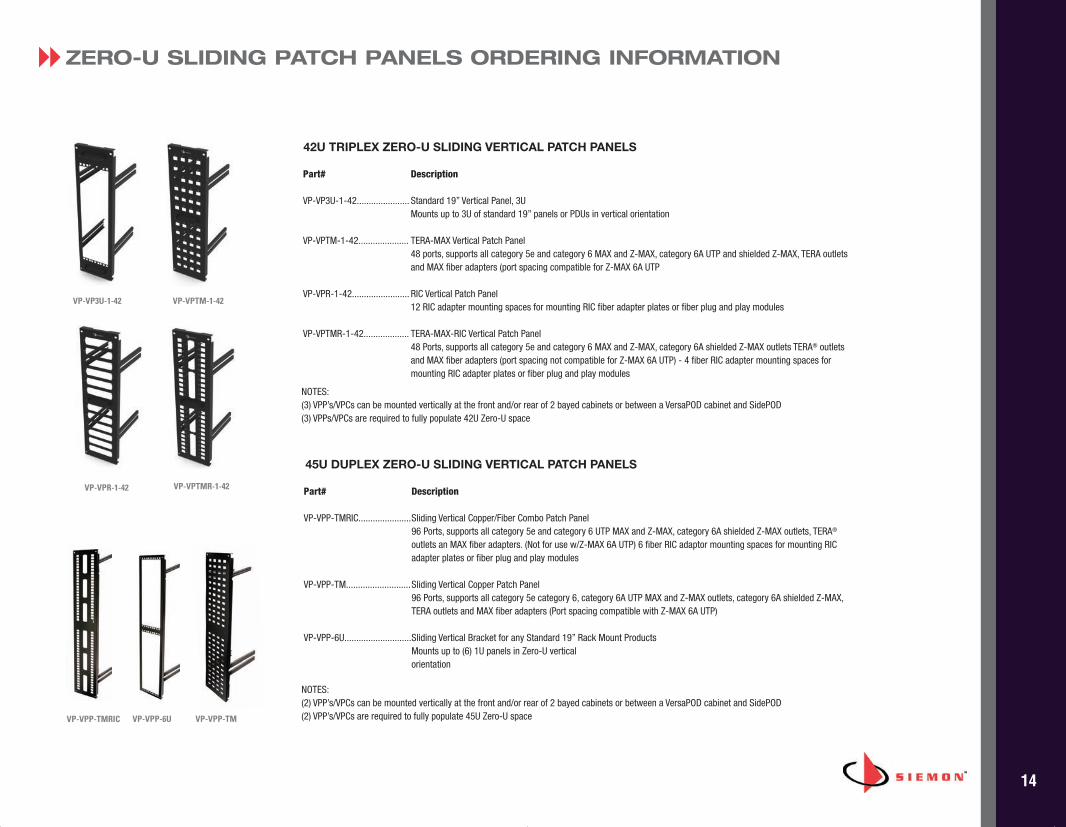
ZERO-U SLIDING PATCH PANELS ORDERING INFORMATION8
VP-VPP-TMRIC VP-VPP-TMVP-VPP-6U
45U DUPLEX ZERO-U SLIDING VERTICAL PATCH PANELS
Part# Description
VP-VPP-TMRIC......................Sliding Vertical Copper/Fiber Combo Patch Panel 96 Ports, supports all category 5e and category 6 UTP MAX and Z-MAX, category 6A shielded Z-MAX outlets, TERA®
outlets an MAX fiber adapters. (Not for use w/Z-MAX 6A UTP) 6 fiber RIC adaptor mounting spaces for mounting RICadapter plates or fiber plug and play modules
VP-VPP-TM...........................Sliding Vertical Copper Patch Panel96 Ports, supports all category 5e category 6, category 6A UTP MAX and Z-MAX outlets, category 6A shielded Z-MAX,TERA outlets and MAX fiber adapters (Port spacing compatible with Z-MAX 6A UTP)
VP-VPP-6U............................Sliding Vertical Bracket for any Standard 19” Rack Mount Products Mounts up to (6) 1U panels in Zero-U vertical orientation
42U TRIPLEX ZERO-U SLIDING VERTICAL PATCH PANELS
Part# Description
VP-VP3U-1-42...................... Standard 19” Vertical Panel, 3U Mounts up to 3U of standard 19” panels or PDUs in vertical orientation
VP-VPTM-1-42..................... TERA-MAX Vertical Patch Panel48 ports, supports all category 5e and category 6 MAX and Z-MAX, category 6A UTP and shielded Z-MAX, TERA outletsand MAX fiber adapters (port spacing compatible for Z-MAX 6A UTP
VP-VPR-1-42........................ RIC Vertical Patch Panel 12 RIC adapter mounting spaces for mounting RIC fiber adapter plates or fiber plug and play modules
VP-VPTMR-1-42................... TERA-MAX-RIC Vertical Patch Panel 48 Ports, supports all category 5e and category 6 MAX and Z-MAX, category 6A shielded Z-MAX outlets TERA® outletsand MAX fiber adapters (port spacing not compatible for Z-MAX 6A UTP) - 4 fiber RIC adapter mounting spaces formounting RIC adapter plates or fiber plug and play modules
VP-VP3U-1-42 VP-VPTM-1-42
VP-VPR-1-42 VP-VPTMR-1-42
NOTES: (3) VPP’s/VPCs can be mounted vertically at the front and/or rear of 2 bayed cabinets or between a VersaPOD cabinet and SidePOD(3) VPPs/VPCs are required to fully populate 42U Zero-U space
NOTES: (2) VPP’s/VPCs can be mounted vertically at the front and/or rear of 2 bayed cabinets or between a VersaPOD cabinet and SidePOD(2) VPP’s/VPCs are required to fully populate 45U Zero-U space
BRC_VPOD_US_REV_J.qxp_J 12/15/16 4:34 PM Page 16
15
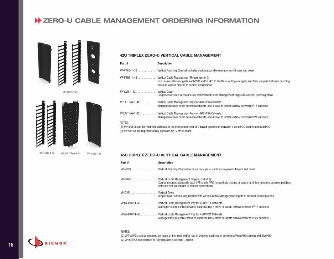
ZERO-U CABLE MANAGEMENT ORDERING INFORMATION8
Part # Description
VP-VPC6-1-42 . . . . . . . . . . . . . Vertical Patching Channel includes back plate, cable management fingers and cover
VP-FGR6-1-42 . . . . . . . . . . . . . Vertical Cable Management Fingers (set of 2) Can be mounted alongside each VPP and/or VPC to facilitate routing of copper and fiber jumpers between patchingfields as well as cabinet to cabinet connections
VP-CVR-1-42 . . . . . . . . . . . . . . Vertical CoverHinged cover used in conjunction with Vertical Cable Management fingers to conceal patching areas
VP1A-TRAY-1-42 . . . . . . . . . . . .Vertical Cable Management Tray for 42U VP1A CabinetsManages/secures cable between cabinets, use 4 trays to isolate airflow between VP1A cabinets
VP2A-TRAY-1-42 . . . . . . . . . . . .Vertical Cable Management Tray for 42U VP2A CabinetsManages/secures cable between cabinets, use 4 trays to isolate airflow between VP2A cabinets
42U TRIPLEX ZERO-U VERTICAL CABLE MANAGEMENT
VP-VPC6-1-42
Part # Description
VP-VPC6 . . . . . . . . . . . . . . . . . . Vertical Patching Channel includes back plate, cable management fingers and cover
VP-FGR6 . . . . . . . . . . . . . . . . . .Vertical Cable Management Fingers, (set of 2)Can be mounted alongside each VPP and/or VPC to facilitate routing of copper and fiber jumpers between patchingfields as well as cabinet to cabinet connections
VP-CVR . . . . . . . . . . . . . . . . . . .Vertical CoverHinged cover used in conjunction with Vertical Cable Management fingers to conceal patching areas
VP1A-TRAY-1-45 . . . . . . . . . . . .Vertical Cable Management Tray for 45U VP1A CabinetsManages/secures cable between cabinets, use 4 trays to isolate airflow between VP1A cabinets
VP2A-TRAY-1-45 . . . . . . . . . . . .Vertical Cable Management Tray for 45U VP2A CabinetsManages/secures cable between cabinets, use 4 trays to isolate airflow between VP2A cabinets
45U DUPLEX ZERO-U VERTICAL CABLE MANAGEMENTVP-FGR6-1-42 VP(X)A-TRAY-1-42 VP-CVR-1-42
NOTES: (3) VPP’s/VPCs can be mounted vertically at the front and/or rear of 2 bayed cabinets or between a VersaPOD cabinet and SidePOD(3) VPPs/VPCs are required to fully populate 42U Zero-U space
NOTES: (2) VPP’s/VPCs can be mounted vertically at the front and/or rear of 2 bayed cabinets or between a VersaPOD cabinet and SidePOD(2) VPPs/VPCs are required to fully populate 45U Zero-U space
BRC_VPOD_US_REV_J.qxp_J 12/15/16 4:34 PM Page 17
16
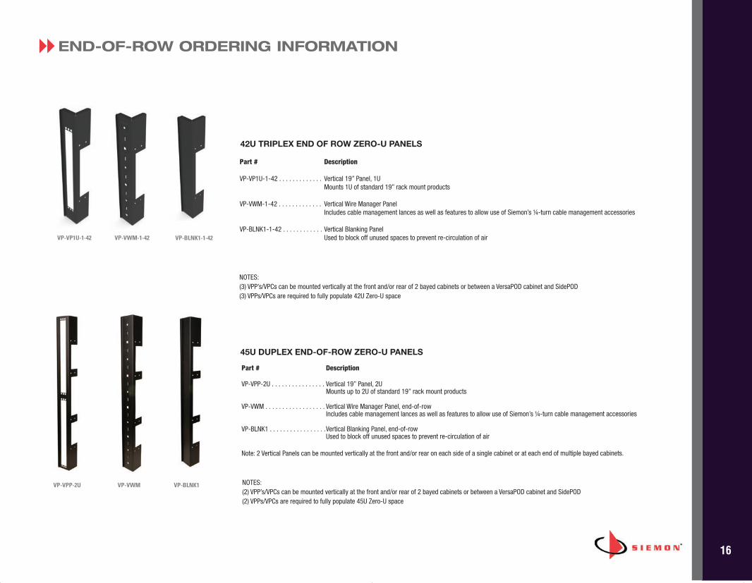
Part # Description
VP-VP1U-1-42 . . . . . . . . . . . . . Vertical 19” Panel, 1UMounts 1U of standard 19” rack mount products
VP-VWM-1-42 . . . . . . . . . . . . . Vertical Wire Manager PanelIncludes cable management lances as well as features to allow use of Siemon’s ¼-turn cable management accessories
VP-BLNK1-1-42 . . . . . . . . . . . . Vertical Blanking PanelUsed to block off unused spaces to prevent re-circulation of air
42U TRIPLEX END OF ROW ZERO-U PANELS
VP-VP1U-1-42 VP-VWM-1-42 VP-BLNK1-1-42
END-OF-ROW ORDERING INFORMATION8
VP-VWMVP-VPP-2U VP-BLNK1
Part # Description
VP-VPP-2U . . . . . . . . . . . . . . . . Vertical 19” Panel, 2UMounts up to 2U of standard 19” rack mount products
VP-VWM . . . . . . . . . . . . . . . . . . Vertical Wire Manager Panel, end-of-rowIncludes cable management lances as well as features to allow use of Siemon’s ¼-turn cable management accessories
VP-BLNK1 . . . . . . . . . . . . . . . . .Vertical Blanking Panel, end-of-rowUsed to block off unused spaces to prevent re-circulation of air
Note: 2 Vertical Panels can be mounted vertically at the front and/or rear on each side of a single cabinet or at each end of multiple bayed cabinets.
45U DUPLEX END-OF-ROW ZERO-U PANELS
NOTES: (3) VPP’s/VPCs can be mounted vertically at the front and/or rear of 2 bayed cabinets or between a VersaPOD cabinet and SidePOD(3) VPPs/VPCs are required to fully populate 42U Zero-U space
NOTES: (2) VPP’s/VPCs can be mounted vertically at the front and/or rear of 2 bayed cabinets or between a VersaPOD cabinet and SidePOD(2) VPPs/VPCs are required to fully populate 45U Zero-U space
BRC_VPOD_US_REV_J.qxp_J 12/15/16 4:34 PM Page 18
17
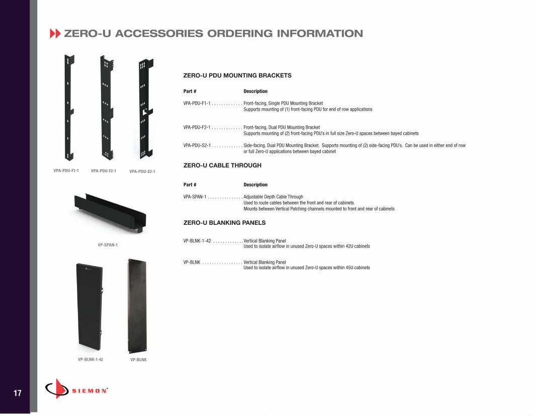
ZERO-U ACCESSORIES ORDERING INFORMATION8
VP-SPAN-1
VP-BLNK-1-42
Part # Description
VPA-PDU-F1-1 . . . . . . . . . . . . . Front-facing, Single PDU Mounting BracketSupports mounting of (1) front-facing PDU for end of row applications
VPA-PDU-F2-1 . . . . . . . . . . . . . Front-facing, Dual PDU Mounting Bracket Supports mounting of (2) front-facing PDU’s in full size Zero-U spaces between bayed cabinets
VPA-PDU-S2-1 . . . . . . . . . . . . . Side-facing, Dual PDU Mounting Bracket. Supports mounting of (2) side-facing PDU’s. Can be used in either end of rowor full Zero-U applications between bayed cabinet
ZERO-U CABLE THROUGH
Part # Description
VPA-SPAN-1 . . . . . . . . . . . . . . . Adjustable Depth Cable ThroughUsed to route cables between the front and rear of cabinets. Mounts between Vertical Patching channels mounted to front and rear of cabinets
ZERO-U BLANKING PANELS
VP-BLNK-1-42 . . . . . . . . . . . . .Vertical Blanking PanelUsed to isolate airflow in unused Zero-U spaces within 42U cabinets
VP-BLNK . . . . . . . . . . . . . . . . . Vertical Blanking PanelUsed to isolate airflow in unused Zero-U spaces within 45U cabinets
ZERO-U PDU MOUNTING BRACKETS
VPA-PDU-F1-1 VPA-PDU-F2-1 VPA-PDU-S2-1
VP-BLNK
BRC_VPOD_US_REV_J.qxp_J 12/15/16 4:34 PM Page 19
18
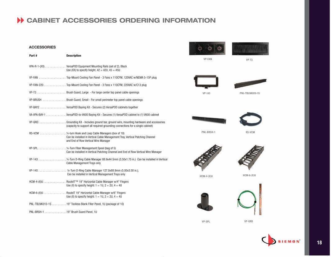
Part # Description
VPA-R-1-(XX) . . . . . . . . . . . . . . VersaPOD Equipment Mounting Rails (set of 2), Black Use (XX) to specify height. 42 = 42U, 45 = 45U
VP-FAN . . . . . . . . . . . . . . . . . . Top-Mount Cooling Fan Panel - 3 Fans x 110CFM, 120VAC w/NEMA 5-15P plug
VP-FAN-220 . . . . . . . . . . . . . . . Top-Mount Cooling Fan Panel - 3 Fans x 110CFM, 220VAC w/C13 plug
VP-T3 . . . . . . . . . . . . . . . . . . . Brush Guard, Large - For large center top panel cable openings
VP-BRUSH . . . . . . . . . . . . . . . . Brush Guard, Small - For small perimeter top panel cable openings
VP-BAY2 . . . . . . . . . . . . . . . . . VersaPOD Baying Kit - Secures (2) VersaPOD cabinets together
VA-VPA-BAY-1 . . . . . . . . . . . . . .VersaPOD-to-V600 Baying Kit - Secures (1) VersaPOD cabinet to (1) V600 cabinet
VP-GRD . . . . . . . . . . . . . . . . . . Grounding Kit - Includes ground bar, ground wire, mounting hardware and accessories (capacity to support all required grounding connections for a single cabinet)
RS-VCM . . . . . . . . . . . . . . . . . .¼-turn Hook and Loop Cable Managers (box of 10) Can be installed in Vertical Cable Management Tray, Vertical Patching Channel and End of Row Vertical Wire Manager
VP-SPL . . . . . . . . . . . . . . . . . . . ¼-Turn Fiber Management Spool (bag of 5)Can be installed in Vertical Patching Channel and End of Row Vertical Wire Manager
VP-143 . . . . . . . . . . . . . . . . . . . ¼-Turn D-Ring Cable Manager 88.9x44.5mm (3.50x1.75 in.) Can be installed in VerticalCable Management Trays only
VP-145 . . . . . . . . . . . . . . . . . . . ¼-Turn D-Ring Cable Manager 127.0x88.9mm (5.00x3.50 in.),Can be installed in Vertical Management Trays only
HCM-4-(X)U . . . . . . . . . . . . . . . RouteIT™ 19” Horizontal Cable Manager w/4” Fingers Use (X) to specify height: 1 = 1U, 2 = 2U, 4 = 4U
HCM-6-(X)U . . . . . . . . . . . . . . . RouteIT 19” Horizontal Cable Manager w/6” Fingers Use (X) to specify height: 1 = 1U, 2 = 2U, 4 = 4U
PNL-TBLNK010-1S . . . . . . . . . . 19” Toolless Blank Filler Panel, 1U (package of 10)
PNL-BRSH-1 . . . . . . . . . . . . . . .19” Brush Guard Panel, 1U
ACCESSORIES
CABINET ACCESSORIES ORDERING INFORMATION8
VP-GRD
VP-FAN VP-T3
VP-143 PNL-TBLNK010-1S
RS-VCM
HCM-4-(X)U HCM-6-(X)U
VP-SPL
PNL-BRSH-1
BRC_VPOD_US_REV_J.qxp_J 12/15/16 4:34 PM Page 20
WWW.SIEMON.COM
Because we continuously improve our products, Siemon reserves the right to change specifications and availability without prior notice.
Worldwide Headquarters North AmericaWatertown, CT USAPhone (1 ) 860 945 4200
Regional Headquarters Europe Russia AfricaChertsy, Surrey, EnglandPhone (44 ) 0 1932 571771
Regional Headquarters ChinaShanghai, P.R. ChinaPhone (86) 215385 0303
Regional Headquarters Latin America Bogota, ColombiaPhone (571) 657 1950/51/52
Regional Headquarters India Middle EastDubai, United Arab EmiratesPhone (971) 4 3689743
Siemon Interconnect SolutionsWatertown, CT USAPhone (1 ) 860 945 4213 USwww.siemon.com/SIS
Regional HeadquartersAsia PacificSydney, AustraliaPhone (86) 21 5385 0303
BRC_VPOD_US_REV_J.qxp_J 12/15/16 4:33 PM Page 1