Embed Size (px)
Citation preview
2507 W. Geneva Dr.Tempe, Arizona 85282Phone [602] 231-8616
FAX [602] 273-9135www.phxlogistics.com
Data Bus Connector and TerminatorRequirements Document
DB-1001-A Revision C
Phoenix Logistics, Inc. 2 of 17 DB-1001-A REV C
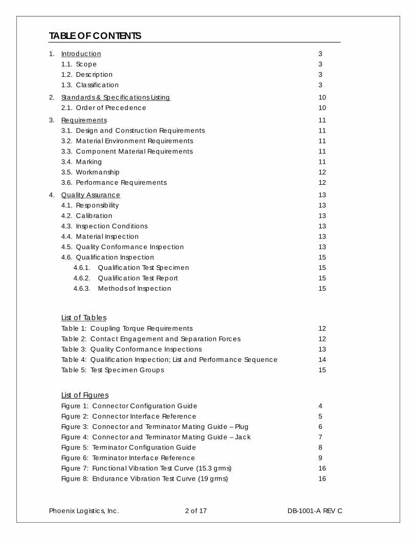
TABLE OF CONTENTS
1. Introduction 3
1.1. Scope 3
1.2. Description 3
1.3. Classification 3
2. Standards & Specifications Listing 10
2.1. Order of Precedence 10
3. Requirements 11
3.1. Design and Construction Requirements 11
3.2. Material Environment Requirements 11
3.3. Component Material Requirements 11
3.4. Marking 11
3.5. Workmanship 12
3.6. Performance Requirements 12
4. Quality Assurance 13
4.1. Responsibility 13
4.2. Calibration 13
4.3. Inspection Conditions 13
4.4. Material Inspection 13
4.5. Quality Conformance Inspection 13
4.6. Qualification Inspection 15
4.6.1. Qualification Test Specimen 15
4.6.2. Qualification Test Report 15
4.6.3. Methods of Inspection 15
List of TablesTable 1: Coupling Torque Requirements 12
Table 2: Contact Engagement and Separation Forces 12
Table 3: Quality Conformance Inspections 13
Table 4: Qualification Inspection; List and Performance Sequence 14
Table 5: Test Specimen Groups 15
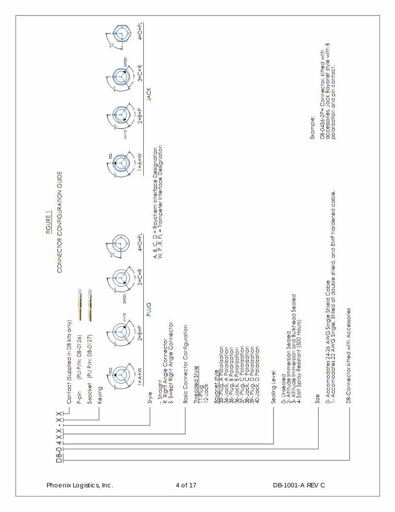
List of FiguresFigure 1: Connector Configuration Guide 4
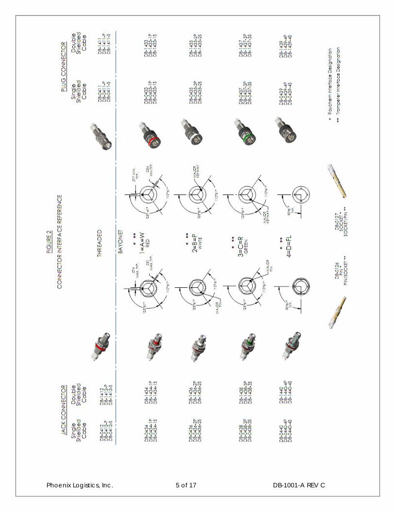
Figure 2: Connector Interface Reference 5
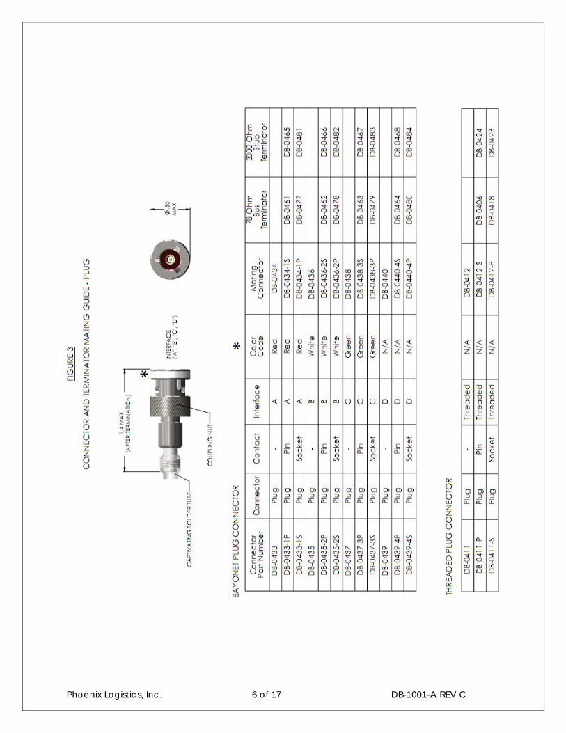
Figure 3: Connector and Terminator Mating Guide – Plug 6
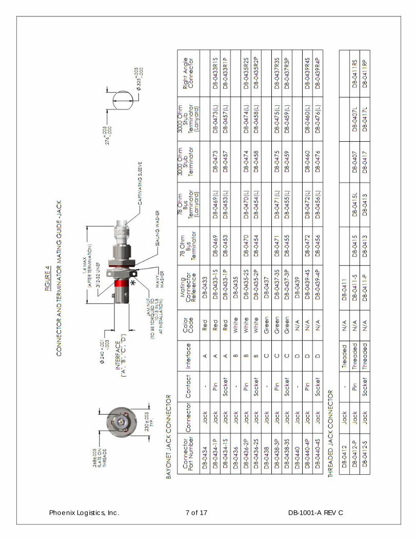
Figure 4: Connector and Terminator Mating Guide – Jack 7
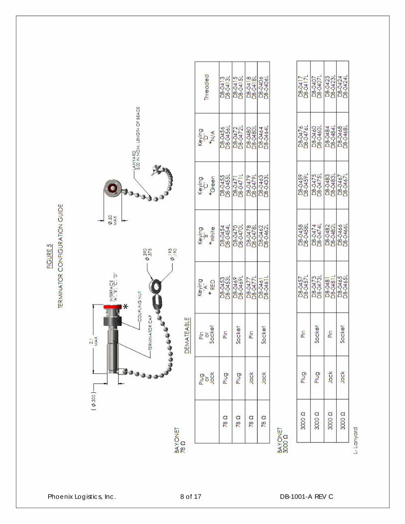
Figure 5: Terminator Configuration Guide 8
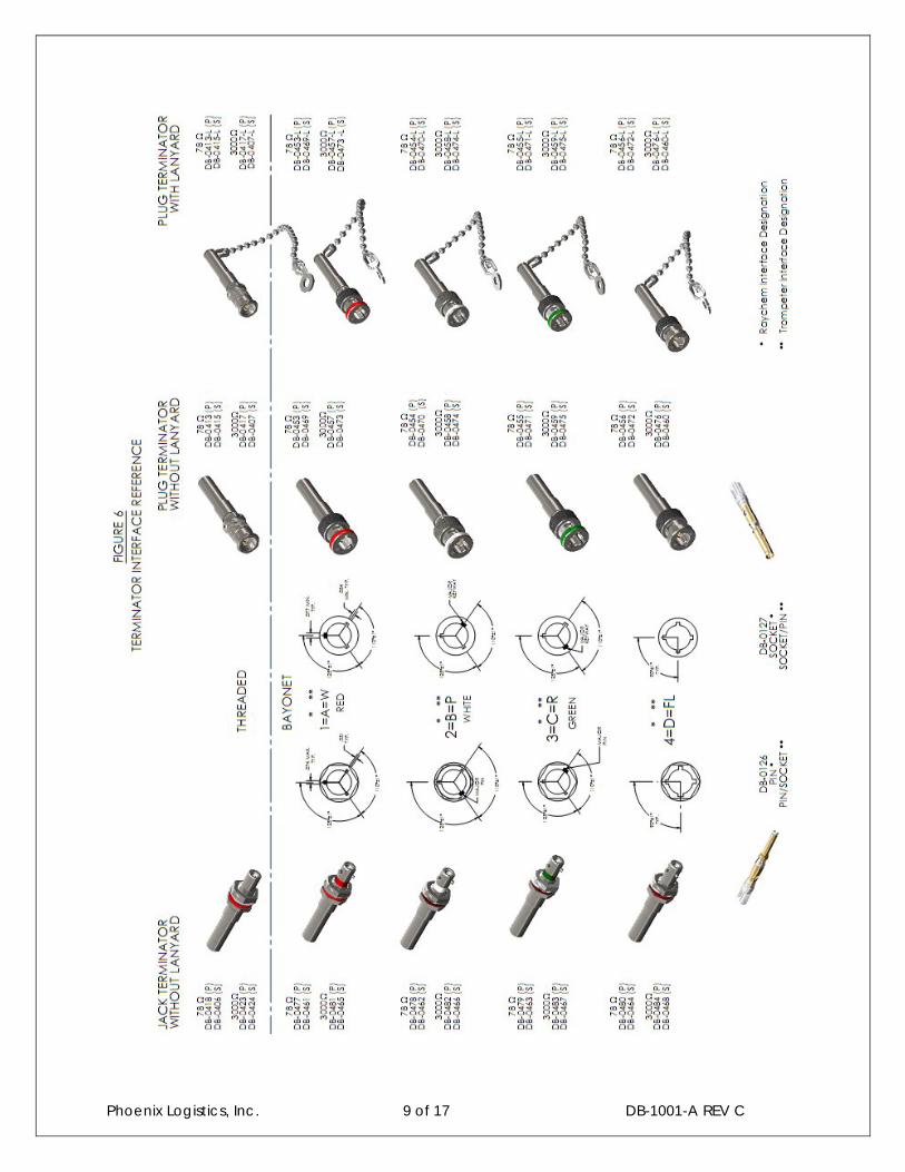
Figure 6: Terminator Interface Reference 9
Figure 7: Functional Vibration Test Curve (15.3 grms) 16
Figure 8: Endurance Vibration Test Curve (19 grms) 16
Phoenix Logistics, Inc. 3 of 17 DB-1001-A REV C
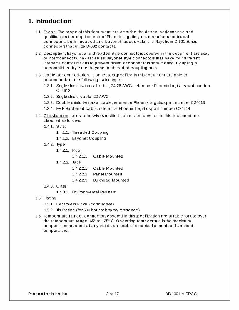
1. Introduction
1.1. Scope. The scope of this document is to describe the design, performance and qualification test requirements of Phoenix Logistics, Inc. manufactured triaxialconnectors; both threaded and bayonet, as equivalent to Raychem D-621 Series connectors that utilize D-602 contacts.
1.2. Description. Bayonet and threaded style connectors covered in this document are used to interconnect twinaxial cables. Bayonet style connectors shall have four different interface configurations to prevent dissimilar connectors from mating. Coupling is accomplished by either bayonet or threaded coupling nuts.
1.3. Cable accommodation. Connectors specified in this document are able to accommodate the following cable types:
1.3.1. Single shield twinaxial cable, 24-26 AWG; reference Phoenix Logistics part numberC24612
1.3.2. Single shield cable, 22 AWG
1.3.3. Double shield twinaxial cable; reference Phoenix Logistics part number C24613
1.3.4. EMP Hardened cable; reference Phoenix Logistics part number C24614
1.4. Classification. Unless otherwise specified connectors covered in this document are classified as follows:
1.4.1. Style:
1.4.1.1. Threaded Coupling
1.4.1.2. Bayonet Coupling
1.4.2. Type:
1.4.2.1. Plug:
1.4.2.1.1. Cable Mounted
1.4.2.2. Jack
1.4.2.2.1. Cable Mounted
1.4.2.2.2. Panel Mounted
1.4.2.2.3. Bulkhead Mounted
1.4.3. Class
1.4.3.1. Environmental Resistant
1.5. Plating.
1.5.1. Electroless Nickel (conductive)
1.5.2. Tin Plating (for 500 hour salt spray resistance)
1.6. Temperature Range. Connectors covered in this specification are suitable for use over the temperature range -65° to 125° C. Operating temperature is the maximum temperature reached at any point as a result of electrical current and ambient temperature.
Phoenix Logistics, Inc. 4 of 17 DB-1001-A REV C
Phoenix Logistics, Inc. 5 of 17 DB-1001-A REV C
Phoenix Logistics, Inc. 6 of 17 DB-1001-A REV C
Phoenix Logistics, Inc. 7 of 17 DB-1001-A REV C
Phoenix Logistics, Inc. 8 of 17 DB-1001-A REV C
Phoenix Logistics, Inc. 9 of 17 DB-1001-A REV C

Phoenix Logistics, Inc. 10 of 17 DB-1001-A REV C
2 Standards and Specifications2.1 Order of Precedence. This document forms part of a specification to the extent
specified herein. In the event that the requirements stated in this document conflict with the applicable drawing, the drawing shall take precedence. If this document and the referenced specifications or standards listed herein conflict, this document shall take precedence.
J-STD-004 Soldering Fluxes
J-STD-006Electronic Grade Solder Alloys and Fluxed and Non-Fluxed Solid Solders
MIL-STD-1285 Marking of Electrical and Electronic Parts
ASTM B16Brass, Rod, Free-Cutting, Bar and Shapes for use in Screw Machines
ASTM B196 Copper-Beryllium Alloy, Rod and Bar
ASTM A582 Stainless Steel, Bars, Free-Machining
AMS-QQ-P-35 Passivation Treatments for Corrosion-Resistant Steel
SAE-AMS-C-26074 Coatings, Electroless Nickel
ASTM B545 Coatings, Electrodeposited Tin
ISO10012-1 Calibration System Requirements
ANSI/ASQ Z1.4 Sampling Procedure
MIL-PRF-49142 Performance Specification for RF Triaxial Connectors
MIL-STD-202 Test Methods for Electronic and Electrical Component Parts
MIL-HDBK-454 General Guidelines for Electronic Equipment
MIL-STD-810Environmental Engineering Considerations and Laboratory Tests
EIA 364 Electrical Connector Test Procedure
SP-R-0022NASA Specification for Vacuum Requirements for Polymeric Materials for Space applications.
FED-STD-H28 Screw-Thread Standards for Federal Standard
Phoenix Logistics, Inc. 11 of 17 DB-1001-A REV C
3 Requirements3.1 Design and Construction Requirements. Connectors shall be designed and constructed
to withstand handling during installation and maintenance. Complete connectors shall consist of a plug or jack body with a removable pin or socket contact and mounting or mating hardware.
3.1.1 Connector Bodies. Plug and Jack bodies shall meet the following requirements:
3.1.1.1 Coupling. Coupling between mating connectors shall be accomplished by means of either bayonet or threaded coupling nuts.
3.1.1.2 Polarization. Connector body polarization shall prevent mating of plug and receptacle shells if the connectors are not in the correct mating position.
3.1.1.3 Connector Keying. Bayonet keying shall prevent the mating of any plug and jack with dissimilar interfaces. Connector keying shall occur before engagement of contacts.
3.1.1.4 Mounting Hardware. Mounting hardware shall be provided with each connector jack. Mounting hardware screws shall conform to FED-STD-H28.
3.1.2 Contacts. Shall be designed to withstand termination and repeated mating and unmating of connectors they are installed into. The mating surfaces shall be smooth and uniform and provide a wiping action during mating.
3.1.3 Interfacial Seal. Shall be designed to eliminate leakage paths between contacts and shell when connector is fully mated and shall be mounted in a way to avoid presenting a FOD hazard in use.
3.1.4 Interchangeability. All components having the same part number shall be completely interchangeable with each other for both installation and during use.
3.1.5 Intermateability. All plug and jack connectors of the same series and interface configuration shall mate with each other.
3.2 Material Requirements
3.2.1 Dissimilar Materials shall be in accordance with Guideline 16 of MIL-HDBK-454.
3.2.2 Fungus Resistance shall be in accordance with Guideline 4 of MIL-HDBK-454 and Method 508.6 of MIL-STD-810.
3.2.3 Hydrolytic Stability shall be in accordance with Guideline 47 of MIL-HDBK-454 for all nonmetallic materials used.
3.2.4 Vacuum Stability shall be in accordance with NASA specification SP-R-022.
3.3 Component Materials
3.3.1 Solder. Solder shall be SN63 per J-STD-006 unless otherwise specified by applicable engineering control drawing.
3.3.2 Connector Housings. Unless otherwise specified, the connector housings, whichincludes coupling nuts, shall be brass per ASTM B16, beryllium copper per ASTM B196, or Stainless Steel per ASTM A582.
3.3.2.1 Finish.
3.3.2.1.1 Electroless Nickel. Components that are electroless nickel plate shall be in accordance with SAE-AMS-C-26074.
3.3.2.1.2 Tin. Components that are tin plate shall be in accordance with ASTM B545.
3.3.3 Materials and Finishes. All other components shall be in accordance withapplicable engineering control drawings.
3.4 Marking. Connectors shall be marked in accordance with MIL-STD-1285 as specified on the applicable engineering control drawings.
Phoenix Logistics, Inc. 12 of 17 DB-1001-A REV C
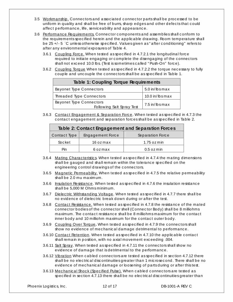
3.5 Workmanship. Connectors and associated connector parts shall be processed to be uniform in quality and shall be free of burrs, sharp edges and other defects that could affect performance, life, serviceability and appearance.
3.6 Performance Requirements. Connector components and assemblies shall conform to the requirements specified herein and the applicable drawing. Room temperature shall be 25 +/- 5 ْC unless otherwise specified. Values given as “after conditioning” refers to after any environmental exposures of Table 4.
3.6.1 Coupling Force. When tested as specified in 4.7.2.1 the longitudinal force required to initiate engaging or complete the disengaging of the connectors shall not exceed 10.0 lbs. (Test is sometimes called “Push-On” force).
3.6.2 Coupling Torque When tested as specified in 4.7.2.2 the torque necessary to fully couple and uncouple the connectors shall be as specified in Table 1.
3.6.3 Contact Engagement & Separation Force. When tested as specified in 4.7.3 thecontact engagement and separation forces shall be as specified in Table 2.
3.6.4 Mating Characteristics. When tested as specified in 4.7.4 the mating dimensions shall be gauged and shall remain within the tolerance specified on the engineering control drawings of the connectors.
3.6.5 Magnetic Permeability. When tested as specified in 4.7.5 the relative permeability shall be 2.0 mu maximum.
3.6.6 Insulation Resistance. When tested as specified in 4.7.6 the insulation resistance shall be 5,000 M Ohms minimum.
3.6.7 Dielectric Withstanding Voltage. When tested as specified in 4.7.7 there shall be no evidence of dielectric break down during or after the test.
3.6.8 Contact Resistance. When tested as specified in 4.7.8 the resistance of the mated connector bodies of the connector shell (Connector Body) shall be 8 milliohms maximum. The contact resistance shall be 8 milliohms maximum for the contact inner body and 10 milliohm maximum for the contact outer body.
3.6.9 Coupling Over Torque. When tested as specified in 4.7.9 the connectors shall show no evidence of mechanical damage detrimental to performance.
3.6.10 Contact Retention. When tested as specified in 4.7.10 the applicable contactshall remain in position, with no axial movement exceeding .004.
3.6.11 Salt Spray. When tested as specified in 4.7.11 the connectors shall show no evidence of damage that is detrimental to the performance.
3.6.12 Vibration When cabled connectors are tested as specified in section 4.7.12 thereshall be no electrical discontinuities greater than 1 microsecond. There shall be no evidence of mechanical damage or loosening of parts during or after this test.
3.6.13 Mechanical Shock (Specified Pulse). When cabled connectors are tested as specified in section 4.7.13 there shall be no electrical discontinuities greater than
Table 1: Coupling Torque RequirementsBayonet Type Connectors 5.0 in/lbs max
Threaded Type Connectors 10.0 in/lbs max
Bayonet Type Connectors Following Salt Spray Test
7.5 in/lbs max
Table 2: Contact Engagement and Separation ForcesContact Type Engagement Force Separation Force
Socket 16 oz max 1.75 oz min
Pin 6 oz max 0.5 oz min
Phoenix Logistics, Inc. 13 of 17 DB-1001-A REV C
1 microsecond. There shall be no evidence of mechanical damage or loosening of parts during or after this test.
3.6.14 Thermal Shock. When tested as specified in 4.7.14 there shall be no evidence of mechanical damage to the connector.
3.6.15 Ruggedness Proof Test. When tested as specified in 4.7.15 the connectors shall show no evidence of mechanical damage detrimental to performance.
3.6.16 Cable Retention Force. When tested as specified in 4.7.16 the connectors shall withstand a minimum of 25 lbs of tensile load and there shall be no evidence of mechanical failure or loosening of parts.
3.6.17 Coupling Mechanism Retention Force. When tested as specified in 4.7.17, the coupling mechanism shall not become dislodged from the connector.
3.6.18 Connector Durability. When tested as specified in 4.7.18 the coupling device shall remain functional and there shall be no evidence of mechanical damage.
3.6.19 Altitude Immersion. When tested as specified in 4.7.19 immersed mated connectors shall meet the IR and DWV stated in 3.6.6 and 3.6.7 respectively, while still immersed.
4 Quality Assurance4.1 Responsibility. Phoenix Logistics, Inc. shall be ultimately responsible for performance of all
inspection requirements as specified herein. Inspection records shall be kept complete and available to the buyer as specified in the contract or order.
4.1.1 A contracted testing facility may be utilized for any or all qualification testrequirements stated in this document as specified in the contract or purchase order to the contracted testing facility. The contracted testing facility may use its own or any other suitable testing facilities. Test records shall be kept complete and available to Phoenix Logistics, Inc. as specified in the contract or order.
4.2 Calibration. A calibration system in accordance with ISO 10012-1shall be utilized on all test and measurement equipment to control the accuracy of the tests performed.
4.3 Inspection Conditions. Unless otherwise stated, all inspection shall be done in accordance with EIA-364.
4.4 Material Inspection. Unless otherwise specified, Phoenix Logistics, Inc. will maintain materials inspection and control, consisting of certification that the materials used are in accordance with the applicable engineering control drawing prior to the assembly of the connectors.
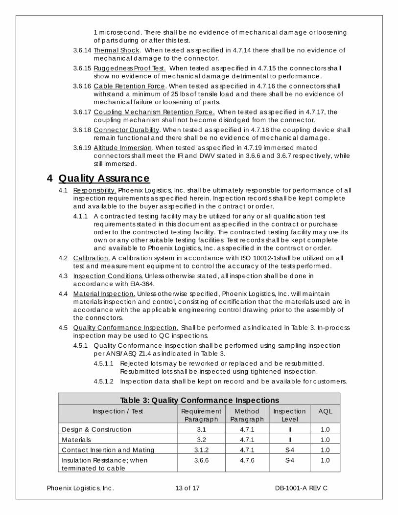
4.5 Quality Conformance Inspection. Shall be performed as indicated in Table 3. In-process inspection may be used to QC inspections.
4.5.1 Quality Conformance Inspection shall be performed using sampling inspection per ANSI/ASQ Z1.4 as indicated in Table 3.
4.5.1.1 Rejected lots may be reworked or replaced and be resubmitted. Resubmitted lots shall be inspected using tightened inspection.
4.5.1.2 Inspection data shall be kept on record and be available for customers.
Table 3: Quality Conformance InspectionsInspection / Test Requirement
ParagraphMethod
ParagraphInspection
LevelAQL
Design & Construction 3.1 4.7.1 II 1.0
Materials 3.2 4.7.1 II 1.0
Contact Insertion and Mating 3.1.2 4.7.1 S-4 1.0
Insulation Resistance; when terminated to cable
3.6.6 4.7.6 S-4 1.0
Phoenix Logistics, Inc. 14 of 17 DB-1001-A REV C
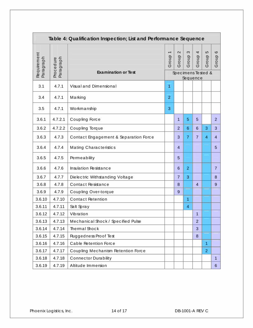
Table 4: Qualification Inspection; List and Performance Sequence
Gro
up
1
Gro
up
2
Gro
up
3
Gro
up
4
Gro
up
5
Gro
up
6
Re
qu
irem
en
t Pa
rag
rap
h
Pro
ce
du
re
Para
gra
ph
Examination or Test Specimens Tested & Sequence
3.1 4.7.1 Visual and Dimensional 1
3.4 4.7.1 Marking 2
3.5 4.7.1 Workmanship 3
3.6.1 4.7.2.1 Coupling Force 1 5 5 2
3.6.2 4.7.2.2 Coupling Torque 2 6 6 3 3
3.6.3 4.7.3 Contact Engagement & Separation Force 3 7 7 4 4
3.6.4 4.7.4 Mating Characteristics 4 5
3.6.5 4.7.5 Permeability 5
3.6.6 4.7.6 Insulation Resistance 6 2 7
3.6.7 4.7.7 Dielectric Withstanding Voltage 7 3 8
3.6.8 4.7.8 Contact Resistance 8 4 9
3.6.9 4.7.9 Coupling Over-torque 9
3.6.10 4.7.10 Contact Retention 1
3.6.11 4.7.11 Salt Spray 4
3.6.12 4.7.12 Vibration 1
3.6.13 4.7.13 Mechanical Shock / Specified Pulse 2
3.6.14 4.7.14 Thermal Shock 3
3.6.15 4.7.15 Ruggedness Proof Test 8
3.6.16 4.7.16 Cable Retention Force 1
3.6.17 4.7.17 Coupling Mechanism Retention Force 2
3.6.18 4.7.18 Connector Durability 1
3.6.19 4.7.19 Altitude Immersion 6
Phoenix Logistics, Inc. 15 of 17 DB-1001-A REV C
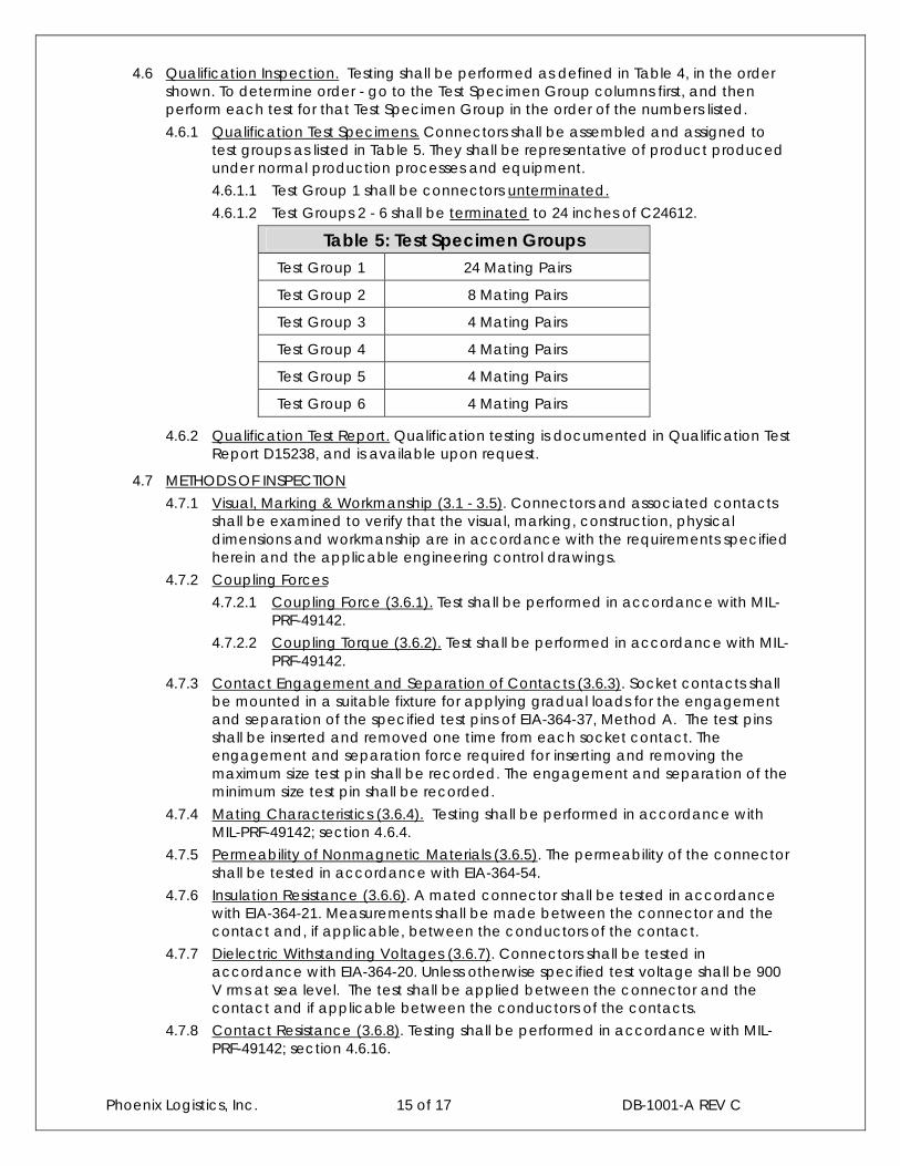
4.6 Qualification Inspection. Testing shall be performed as defined in Table 4, in the order shown. To determine order - go to the Test Specimen Group columns first, and then perform each test for that Test Specimen Group in the order of the numbers listed.
4.6.1 Qualification Test Specimens. Connectors shall be assembled and assigned to test groups as listed in Table 5. They shall be representative of product produced under normal production processes and equipment.
4.6.1.1 Test Group 1 shall be connectors unterminated.
4.6.1.2 Test Groups 2 - 6 shall be terminated to 24 inches of C24612.
Table 5: Test Specimen GroupsTest Group 1 24 Mating Pairs
Test Group 2 8 Mating Pairs
Test Group 3 4 Mating Pairs
Test Group 4 4 Mating Pairs
Test Group 5 4 Mating Pairs
Test Group 6 4 Mating Pairs
4.6.2 Qualification Test Report. Qualification testing is documented in Qualification Test Report D15238, and is available upon request.
4.7 METHODS OF INSPECTION
4.7.1 Visual, Marking & Workmanship (3.1 - 3.5). Connectors and associated contacts shall be examined to verify that the visual, marking, construction, physical dimensions and workmanship are in accordance with the requirements specified herein and the applicable engineering control drawings.
4.7.2 Coupling Forces
4.7.2.1 Coupling Force (3.6.1). Test shall be performed in accordance with MIL-PRF-49142.
4.7.2.2 Coupling Torque (3.6.2). Test shall be performed in accordance with MIL-PRF-49142.
4.7.3 Contact Engagement and Separation of Contacts (3.6.3). Socket contacts shall be mounted in a suitable fixture for applying gradual loads for the engagement and separation of the specified test pins of EIA-364-37, Method A. The test pins shall be inserted and removed one time from each socket contact. The engagement and separation force required for inserting and removing the maximum size test pin shall be recorded. The engagement and separation of the minimum size test pin shall be recorded.
4.7.4 Mating Characteristics (3.6.4). Testing shall be performed in accordance with MIL-PRF-49142; section 4.6.4.
4.7.5 Permeability of Nonmagnetic Materials (3.6.5). The permeability of the connector shall be tested in accordance with EIA-364-54.
4.7.6 Insulation Resistance (3.6.6). A mated connector shall be tested in accordance with EIA-364-21. Measurements shall be made between the connector and the contact and, if applicable, between the conductors of the contact.
4.7.7 Dielectric Withstanding Voltages (3.6.7). Connectors shall be tested in accordance with EIA-364-20. Unless otherwise specified test voltage shall be 900V rms at sea level. The test shall be applied between the connector and the contact and if applicable between the conductors of the contacts.
4.7.8 Contact Resistance (3.6.8). Testing shall be performed in accordance with MIL-PRF-49142; section 4.6.16.
Phoenix Logistics, Inc. 16 of 17 DB-1001-A REV C
4.7.9 Coupling Over Torque (3.6.9). Terminated connector assemblies shall be mated in the normal manner. A torque of 150% of the maximum coupling torque specified shall then be applied to the coupling nut.
4.7.10 Contact Retention (3.6.10). An axial load of 10 lbs shall be applied to the front face of the contact of the subject connector. This load shall be held for 5 to 10 seconds in accordance with MIL-PRF-49142.
4.7.11 Salt Spray (3.6.11). Terminated mating connectors shall be mated and unmated 50 times prior to being exposed 452 hours of salt fog in accordance with EIA-364-26. The connector shall then be unmated and exposed for 48 hours of salt fog, followed by 450 mating and un-mating cycles (The 450 mating cycles are done after salt fog and not during).
4.7.12 Vibration (3.6.12).
NOTE: Cabled connectors shall be mounted in a manner similar to actual use and electrical continuity shall be monitored throughout the test.
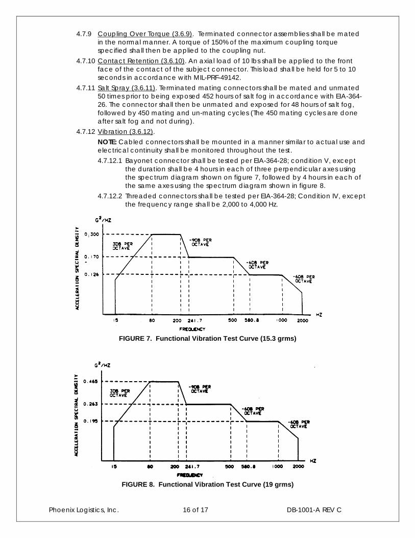
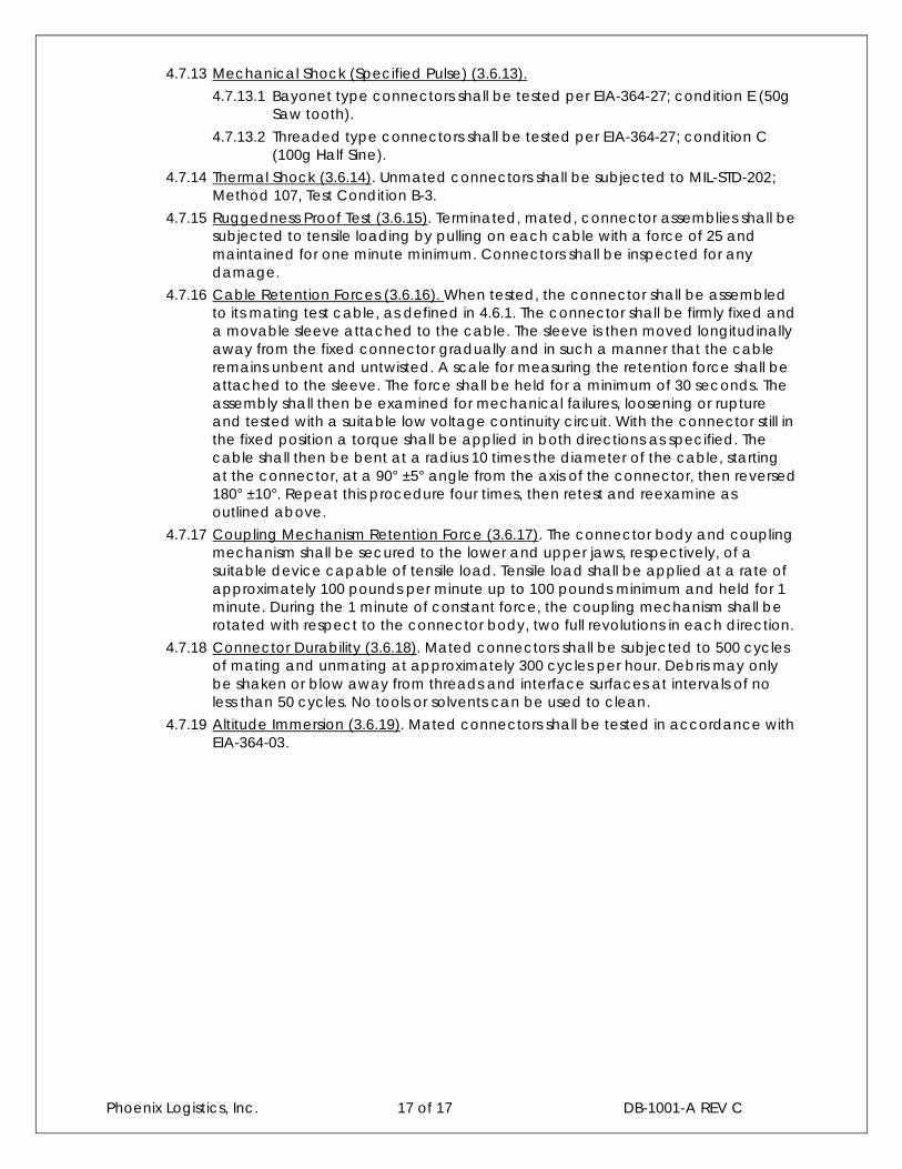
4.7.12.1 Bayonet connector shall be tested per EIA-364-28; condition V, except the duration shall be 4 hours in each of three perpendicular axes using the spectrum diagram shown on figure 7, followed by 4 hours in each of the same axes using the spectrum diagram shown in figure 8.
4.7.12.2 Threaded connectors shall be tested per EIA-364-28; Condition IV, except the frequency range shall be 2,000 to 4,000 Hz.
FIGURE 7. Functional Vibration Test Curve (15.3 grms)
FIGURE 8. Functional Vibration Test Curve (19 grms)
Phoenix Logistics, Inc. 17 of 17 DB-1001-A REV C
4.7.13 Mechanical Shock (Specified Pulse) (3.6.13).
4.7.13.1 Bayonet type connectors shall be tested per EIA-364-27; condition E (50g Saw tooth).
4.7.13.2 Threaded type connectors shall be tested per EIA-364-27; condition C(100g Half Sine).
4.7.14 Thermal Shock (3.6.14). Unmated connectors shall be subjected to MIL-STD-202; Method 107, Test Condition B-3.
4.7.15 Ruggedness Proof Test (3.6.15). Terminated, mated, connector assemblies shall be subjected to tensile loading by pulling on each cable with a force of 25 and maintained for one minute minimum. Connectors shall be inspected for any damage.
4.7.16 Cable Retention Forces (3.6.16). When tested, the connector shall be assembled to its mating test cable, as defined in 4.6.1. The connector shall be firmly fixed and a movable sleeve attached to the cable. The sleeve is then moved longitudinally away from the fixed connector gradually and in such a manner that the cable remains unbent and untwisted. A scale for measuring the retention force shall be attached to the sleeve. The force shall be held for a minimum of 30 seconds. The assembly shall then be examined for mechanical failures, loosening or rupture and tested with a suitable low voltage continuity circuit. With the connector still in the fixed position a torque shall be applied in both directions as specified. The cable shall then be bent at a radius 10 times the diameter of the cable, starting at the connector, at a 90° ±5° angle from the axis of the connector, then reversed 180° ±10°. Repeat this procedure four times, then retest and reexamine as outlined above.
4.7.17 Coupling Mechanism Retention Force (3.6.17). The connector body and coupling mechanism shall be secured to the lower and upper jaws, respectively, of a suitable device capable of tensile load. Tensile load shall be applied at a rate of approximately 100 pounds per minute up to 100 pounds minimum and held for 1 minute. During the 1 minute of constant force, the coupling mechanism shall be rotated with respect to the connector body, two full revolutions in each direction.
4.7.18 Connector Durability (3.6.18). Mated connectors shall be subjected to 500 cycles of mating and unmating at approximately 300 cycles per hour. Debris may only be shaken or blow away from threads and interface surfaces at intervals of no less than 50 cycles. No tools or solvents can be used to clean.
4.7.19 Altitude Immersion (3.6.19). Mated connectors shall be tested in accordance withEIA-364-03.