Embed Size (px)
Citation preview

DEPARTMENT OF CORPORATE AND INFORMATION SERVICES
Data and voice cablingstandard
June 2018Version 5.0

Document control
DEPARTMENT OF CORPORATE AND INFORMATION SERVICES Page 2 of 4326 June 2018 Version 5.0
Document detailsDocument title Data and voice cabling standard
Contact detailsDigital Policy unit, Department of Corporate and Information Services(DCIS), Northern Territory Government (NTG)[email protected]
Date and version 26 June 2018Version 5.0
Approved by NTG ICT Leadership GroupDate approved 11 April 2016Document review(for example, annually) As and when required
Published Published on the NTG intranet and the DCIS Internet (in full)
Change historyVersion Date Author Change details
1.1 June 2004 DCIS Updated standards and addedcategory 6 UTP Specifications.
1.2 October 2007 DCISUpdated standards for optic fibrecabling and category 6A class EA UTPand category 6A class EA F/UTP.Added category seven specifications.
1.3 November 2009 DCIS
Minor change to standards for commsroom specification including coolingrequirements. Minor changes tooverview page to highlight that Cat 7cabling standard is to be used for allNTG greenfield sites.
1.4 July 2012 DCIS
Complete review of the entiredocument to include the latestAustralian standards, updaterequirements and correct minoromissions.
2.0 February 2013 DCIS
Updated department names andchanged version from 1.x to 2.x asJuly 2012 was a major update. Minorgrammar corrections throughoutdocument. Updated cabinet height to2.2 m. Clarified power railrequirements for equipment cabinets.
3.0 January 2016 DCIS
Review to highlight category 6A classEA cabling standard as the initialstandard for NTG installations .Updateto include current trends. Includedunderground cabling, UPS,communication room labelling, andcommunication cabinets. Expandedthe standard to include designrequirements. Distributed to agenciesfor comment.

Document control
DEPARTMENT OF CORPORATE AND INFORMATION SERVICES Page 3 of 4326 June 2018 Version 5.0
Change history
3.1 March 2016 DCIS Revised the document based onagency comments on v 3.0.
4.0 April 2016 DCIS Approved by ICT Leadership Group.
4.1 May 2016 DCIS Minor editorial changes
4.2 15 September 2016 DCIS Document name change, and minorediting to reflect name change.
4.3 28 November 2016 DCIS
Updates to labelling, minimum size ofwall mounted communicationscabinets, securing of communicationcabinets to floors, andcommunications room flooring.
5.0 26 June 2018 DCIS
Cat 6A F/UTP as minimum standard.Updates to fly leads and patch leadsdistribution, wall mounted cabinetspecifications and layout. Includingsome minor editorial changes.
Table of Contents
DEPARTMENT OF CORPORATE AND INFORMATION SERVICES Page 4 of 4326 June 2018 Version 5.0
Contents1 Introduction ............................................................................................................................ 6
1.1.......Overview....................................................................................................................... 6
2 Standard ................................................................................................................................. 82.1.......Introduction................................................................................................................... 8
2.1.1 ........General approach .................................................................................................. 82.1.2 ........Supported systems ................................................................................................ 92.1.3 ........Site requirements................................................................................................... 92.1.4 ........Contractor requirements ...................................................................................... 102.1.5 ........NTG project manager .......................................................................................... 112.1.6 ........ ICT project manager ............................................................................................ 112.1.7........ Technical contact ................................................................................................. 112.1.8 ........Site inspection ..................................................................................................... 11
2.2.......General requirements ................................................................................................. 112.2.1 ........General................................................................................................................ 112.2.2 ........Building distributors and floor distributors............................................................. 112.2.3 ........Communications cabinets .................................................................................... 152.2.4 ........ Labelling of building and floor distribution rooms.................................................. 172.2.5 ........ Labelling of communication cabinets.................................................................... 172.2.6 ........ Labelling of wall outlets ........................................................................................ 172.2.7 ........Acceptable methods of labelling........................................................................... 182.2.8 ........Unacceptable methods of labelling ...................................................................... 192.2.9 ........ Labelling patch panels ......................................................................................... 192.2.10...... Labelling optical fibre ........................................................................................... 192.2.11......Uninterrupted power supply (UPS)....................................................................... 192.2.12......Horizontal cabling ................................................................................................ 192.2.13......Vertical cabling installation practices.................................................................... 202.2.14......Work area telecommunication outlets and faceplates .......................................... 202.2.15......Patch panel.......................................................................................................... 212.2.16......Backbone cabling................................................................................................. 212.2.17......Optical fibre.......................................................................................................... 21
2.3.......Terminations............................................................................................................... 222.3.1 ........Horizontal cabling ................................................................................................ 222.3.2 ........Optical fibre.......................................................................................................... 22
2.3.2.1 .......Optical fibre termination enclosures................................................................. 222.3.3 ........Patch leads.......................................................................................................... 23
2.3.3.1 .......Optical fibre ..................................................................................................... 232.3.3.2 ....... Fly leads and patch leads................................................................................ 23
2.3.4 ........ Integrated rear cable management ...................................................................... 242.3.5 ........Physical cable management ................................................................................ 242.3.6 ........Cabling topology .................................................................................................. 242.3.7 ........Equipment cabinet layout..................................................................................... 242.3.8 ........Ducting, cable trays and service poles ................................................................. 26
2.3.8.1 .......Work area........................................................................................................ 262.3.8.2 ....... Ceiling space................................................................................................... 272.3.8.3 ....... Catenary cable support system ....................................................................... 27
2.3.9 ........Building riser ........................................................................................................ 272.4.......Installation of underground fibre.................................................................................. 27
2.4.1 ........High level design.................................................................................................. 272.4.2 ........Supply and installation of conduit......................................................................... 272.4.3 ........Supply and installation of pits............................................................................... 28

Table of Contents
DEPARTMENT OF CORPORATE AND INFORMATION SERVICES Page 5 of 4326 June 2018 Version 5.0
2.4.4 ........Backfill and reinstatement of excavation .............................................................. 292.4.5 ........Reinstatement of surfaces ................................................................................... 292.4.6 ........Care of optical fibre cable .................................................................................... 292.4.7 ........Pre-installation testing.......................................................................................... 302.4.8 ........ ‘As Constructed’ drawings.................................................................................... 30
2.5.......Testing........................................................................................................................ 312.5.1 ........Horizontal cabling ................................................................................................ 312.5.2........Backbone optical fibre.......................................................................................... 312.5.3 ........Documentation..................................................................................................... 31
2.6.......Standards ................................................................................................................... 332.6.1 ........Australian/New Zealand standards ...................................................................... 332.6.2 ........ACMA Technical standards.................................................................................. 332.6.3 ........ International Standards........................................................................................ 33
3 Additional cabling system installation and test specifications ........................................ 343.1.......Separation from electrical supply ................................................................................ 343.2.......Quality and performance expectations........................................................................ 343.3.......Ancillary considerations .............................................................................................. 363.4.......Entrance facility (EF) or building distributor................................................................. 363.5.......Certification................................................................................................................. 36
4 Additional requirements for category 7A class FA............................................................ 374.1.......General....................................................................................................................... 37
4.1.1 ........Site configuration ................................................................................................. 374.1.2 ........ Installer requirements .......................................................................................... 374.1.3 ........Required installer training .................................................................................... 384.1.4 ........Manufacturer quality and product substitutions .................................................... 384.1.5 ........Outlets ................................................................................................................. 384.1.6 ........ Fly leads and patch leads .................................................................................... 39
4.2.......Installation .................................................................................................................. 394.2.1 ........Site survey........................................................................................................... 394.2.2 ........Horizontal cable routing ....................................................................................... 394.2.3 ........Pulling tension ..................................................................................................... 404.2.4 ........Bend radius.......................................................................................................... 404.2.5 ........Slack.................................................................................................................... 404.2.6 ........Grounding............................................................................................................ 404.2.7 ........ Testing................................................................................................................. 40
4.2.7.1 ....... Category 7A class FA testing.............................................................................. 404.2.7.2 ....... Test equipment criteria .................................................................................... 40
4.3.......Warranty..................................................................................................................... 414.3.1 ........System warranty .................................................................................................. 414.3.2 ........Applications supported......................................................................................... 41
5 Requirements for wireless networking............................................................................... 415.1.......General....................................................................................................................... 41
5.1.1 ........Wireless survey ................................................................................................... 415.1.2 ........WAP hardware installation ................................................................................... 41
6 Requirements for closed circuit television (CCTV) ........................................................... 426.1.......General....................................................................................................................... 42
6.1.1 ........CCTV hardware installation ................................................................................. 42

Data and voice cabling standard
DEPARTMENT OF CORPORATE AND INFORMATION SERVICES Page 6 of 4326 June 2018 Version 5.0
1 IntroductionImportant: It is essential that the Department of Corporate and Information Services (DCIS)Information and Communication Technology (ICT) Project Management Office be engaged at theearliest opportunity by design staff, when considering projects that involve network infrastructure,particularly ICT cabling. Specialist advice and direction will be provided with regard to theappropriate infrastructure, in the design and construction phases of the project, to ensure that thestandards are adhered to, and that the project is delivered in accordance with the recommendedstandards and procedures.
The Australian and international standards that apply to this document are listed in the clauseentitled Standards, and will be enforced. This document is a supplement to those standards.
All design documentation on Greenfield sites (new buildings), and significant renovations, must bepresented to the DCIS ICT Project Management Office for review prior to going to tender.
It should be noted that some Northern Territory Government (NTG) agencies may have specificrequirements related to some sites including remote sites. It is recommended that contractorsengage NTG agency ICT staff or the assigned NTG project manager prior to commencing work.
1.1 OverviewThe following table displays the NTG accepted cable categories and the recognised bandwidth foreach of those categories.
Bandwidth Category Class1 MHz to 500 MHz Category 6A Class EA
1 MHz to 1000 MHz Category 7A Class FA
Category 5e class D, category 6 class E, category 6A UTP, and category 7 class F, have beendiscontinued for use by the NTG, and are not to be used on any NTG structured cabling projectsunless otherwise approved the DCIS ICT Project Management Office.
The intention is to move to category 6A class EA F/UTP and category 7A class FA. However in thecase of some existing sites exceptions may apply based on:
existing category 5e and category 6 infrastructure
financial considerations.
In these cases a decision will be made based upon consultation with the agency ICT staff and theDCIS ICT Project Management Office.
In general terms, and dependent upon direction from the DCIS ICT Project Management Office,cabling installed for the NTG should be as follows:
Category 6A class EA F/UTP – Category 6A Class EA F/UTP shall be the minimum NTG cablingstandard. Foiled UTP (F/UTP) reduces Electromagnetic Interference (EMI), and has a greaterability to dissipate heat generated by PoE and PoE plus.
Minimum manufacturer’s warranty is 20 years.
The DCIS ICT Project Management Office Category may consider approving the use ofCategory 6A Class EA UTP as an option to Category 6A Class EA F/UTP, only after reviewinga written application detailing the circumstances for the substitution.

Data and voice cabling standard
DEPARTMENT OF CORPORATE AND INFORMATION SERVICES Page 7 of 4326 June 2018 Version 5.0
Category 7A class FA (S/FTP) – optional for Greenfield installations or upgrades to existinglegacy sites.
Category 7A class FA is a fully screened and shielded cable, and is capable of frequencies ofup to, and beyond, 1200 MHz making it uniquely able to support all channels of CATV at862 MHz
Category 7A class FA is currently rated for 10 Gbps data transmission, as a result of theextremely high frequency possible with this class of cable, it is expected that the datatransmission rates will increase over time with hardware advancement. An interim 40 Gbpsstandard has been proposed.
Another feature of the category 7A class FA cabling system is the ability to use and manageindividual pairs of the cable for different applications. Typically one category 7A class FA100 MHz workstation outlet is equivalent to two category 6A class EA 100 MHz workstationoutlets.
Additionally, due to the unique ability of category 7A class FA to carry up to four circuits overone cable, the overall cost benefit between category 6A class EA and category 7A class FAmay be in the order of 20%.
Category 7A class FA S/FTP cabling is best terminated using a TERA style connector whichmakes use of shared pair technology allowing the cable to maximise use of all four pairs in thecable. TERA style patch leads will be required to enable cross patching to Ethernet switchports and workstations network interface cards.
Laser optimised (OM3) laser optimised multimode optical fibre (LOMMF) – For upgradesto legacy sites.
OM3 laser optimised multimode optical fibre is capable of supporting 10 Gbps up to a distanceof 300 m and has a bandwidth rating of 2000 MHz
Laser optimised (OM4) multi- mode optical fibre (MMF) – For Greenfield installations andupgrades to legacy sites.
OM4 laser optimised multi-mode optical fibre is capable of supporting 10 Gbps up to a distanceof 550 m and is best suited in core backbone applications.
Single-mode (OS2) optical fibre (SMF) – For Greenfield installations and upgrades to legacysites.
OS2 has a higher bandwidth than OM4, is capable of supporting 10 Gbps up to a distance of80 kms and is best suited for services a great distance apart.
Existing OM1 and OM2 multi-mode fibre is capable of 100 Mbps to 1 Gbps. OM1 and OM2 opticalfibre is not to be used for new NTG installations or upgrades.
Wireless networking should be considered where possible. Refer to the wireless networkingsection in this document.

Data and voice cabling standard
DEPARTMENT OF CORPORATE AND INFORMATION SERVICES Page 8 of 4326 June 2018 Version 5.0
2 StandardThis document describes the standards and practices to be followed in the supply, installation,documentation and testing of data and voice cabling technology used to support the data and voicecommunications services currently in use within the NTG.
2.1 Introduction
2.1.1 General approach
Note: For the purpose of this document, where an Australian, an Australian/New Zealand, orInternational standard is referred to, the intention is that the latest addendum or edition, of thatstandard be used, i.e. AS/NZS 3080:2013 will be referred to as AS/NZS 3080 in this document.
It will be the responsibility of those responding to tenders, to ensure they are referencing the latestversions of the relevant Standards.
Greenfield sites are defined as buildings, sites or floors where the NTG has no existing presencein regard to communications infrastructure (cabling, LAN or WAN).
This specification covers the standard cabling requirements for the NTG Local Area Networks (andother services) utilising category 6A class EA and 7A shielded twisted pair, and multi-mode opticalfibre cables.
Category 7A class FA may be selected for specific infrastructure upgrades and Greenfieldinstallations. All category 7A class FA cabling installations for the NTG must conform toAS/NZS 3080.
In general terms, and dependent upon direction from the DCIS ICT Project Management Office,cabling installed for the NTG should be as follows:
Category 6A class EA F/UTP – The minimum standard to be used. RJ45 connectors are usedwith category 6A class EA F/UTP.
Category 7A class FA (S/FTP) – optional for Greenfield installations, or upgrades at specifiedsites which may have particular requirements. TERA style shared pair technology connectorsare used with category 7A class FA S/FTP. The ICT Project Management Office will advisewhen category 7A class FA is to be utilised.
OM3 multimode optical fibre (LOMMF) – For upgrades at specified sites.
OM4 multi- mode optical fibre (MMF) – For Greenfield installations or upgrades at specifiedsites.
Single- mode optical fibre (SMF) – For Greenfield installations or upgrades at very specificsites where distance is a factor.
In all cases, installation of category 6A class EA F/UTP, category 7A class FA S/FTP multi-mode,and single-mode optical fibre, shall meet or exceed the national and international standardsapplicable to each type.
Structured cabling installations carried out for the NTG will be subject to rigorous quality assuranceinspections in order to ensure that correct installation practises are maintained at all times.

Data and voice cabling standard
DEPARTMENT OF CORPORATE AND INFORMATION SERVICES Page 9 of 4326 June 2018 Version 5.0
2.1.2 Supported systems
The cabling system shall support:
analogue and digital voice applications
data
local area networks (LAN)
PoE and PoE plus.
video and low voltage devices for building controls
management of the common cabling platform.
The systems that shall be supported include, but are not limited to:
Data processing – Mainframe access, client-server, enterprise server, messaging systemsand electronic mail, common document utilisation, client data base, etc.
Data communications – EIA-232-D, RS-422, RS-423, ISDN, Ethernet (10 Base-T, 100 Base-T, 1000 Base-T, 1000 Base-TX and 10 GBase-T), 100 Base VG Any LAN, Token Ring,Twisted Pair-Physical Medium Dependant (TP-PMD) and ATM (155 Mbps, 622 Mbps and1 Gbps).
Voice applications – Digital and analogue PABX and key systems, and Voice over IP (VoIP)applications.
Video – Analogue video, digital video and video conferencing. Additionally CATV can becarried over category 7A class FA.
Building services – Heating ventilation and air conditioning (HVAC) monitoring and control,low voltage devices (equipment sensors, etc.), wall clocks, security, energy monitoring andcontrol, lighting, motion sensors, public address, modular wall systems and paging systems.
2.1.3 Site requirements
Each site may have specific individual requirements which may need a customised solution,however in most cases the layout of structured cabling within NTG owned or leased buildings willconform to a general standard.
The DCIS ICT Project Management Office is able to provide advice on site specific solutions.
Typically, horizontal cabling to the desktop will be either category 6A class EA or category 7A classFA, and the vertical backbone cabling will be OM3 or OM4 multi-mode optic fibre.
Given approval by the DCIS ICT Project Management Office, existing category three voice cablingmay be re-used where suitable, however where a building is being renovated or upgraded, voiceservices will be provided by the specified data cable.
Each floor will have a floor distributor (communications room), with an equipment cabinet withpatch panels for horizontal and vertical cabling. On floors where there are only a small number ofusers, a wall or floor mount cabinet may suffice as a floor distributor after written application forapproval from the DCIS ICT Project Management Office has been given. Please note, there aresome minimum size requirements for all racks – refer to section titled ‘communications cabinets’.
The horizontal cabling topology shall be in the form of a star, with the centre of the star being thefloor distributor. For the larger sites multiple star configurations may be interconnected in a tree ofstars or meshed network.

Data and voice cabling standard
DEPARTMENT OF CORPORATE AND INFORMATION SERVICES Page 10 of 4326 June 2018 Version 5.0
Unless otherwise specified by the DCIS ICT Project Management Office, category 6A class EAcable terminations will use RJ45 connectors, and category 7A class FA terminations will be TERAstyle connectors. Sequencing shall conform to the EIA/TIA 568A standard.
Catenary cable, and wire mesh support systems, will be used to support cabling in the ceilingspace.
Cabling will not be supported by the use of ceiling hangers, or be allowed to rest on the suspendedceilings. Specific details of catenary and tray system requirements are included in the horizontalcabling section of this document.
2.1.4 Contractor requirements
The cabling contractor must:
possess the applicable open cabling registration under the Australian Communications andMedia Authority (ACMA)
follow telecommunication cabling provider rules (CPRs)
comply with the Australian standard AS/CA S009 – Installation requirements for customercabling (wiring rules).
The cabling contractor is required to be the cable manufacturer’s certified installer for that type ofcabling so that a manufacturer’s warranty can be provided at the completion of works.
The cabling contractor must ensure that a minimum of 50% of the installation staff on site at anytime throughout the installation must be certified by the specified cabling manufacturer. Cablingcontractor must comply at all times with all the relevant standards and in particular the applicabletechnical standards.
The cabling contractor shall:
Provide all cabling materials and services for the installation of the cabling system, includingducting (where required).
Site and fix the equipment cabinet in its final position.
Be responsible for the provision of patch panels and wiring management components to beinstalled in the cabinets.
All installed cabling systems shall be fully certified, and warranted for a minimum of 20 years by thetermination equipment, and cable manufacturers. The cabling contractor must be part of themanufacturer's installer’s certification program to achieve the warranty. This warranty should atleast include parts and labour.
On completion of the installation, the contractor shall supply the following:
cable and optical fibre test results in soft copy
patch panel continuity test results
marked up floor plans showing outlet numbers and locations, floor distributors, and risers
consolidation point plans and specifications (if applicable)
manufacturer’s warranty certification
certification that the cabling installation meets, or exceeds, the minimum specified standard.
Data and voice cabling standard
DEPARTMENT OF CORPORATE AND INFORMATION SERVICES Page 11 of 4326 June 2018 Version 5.0
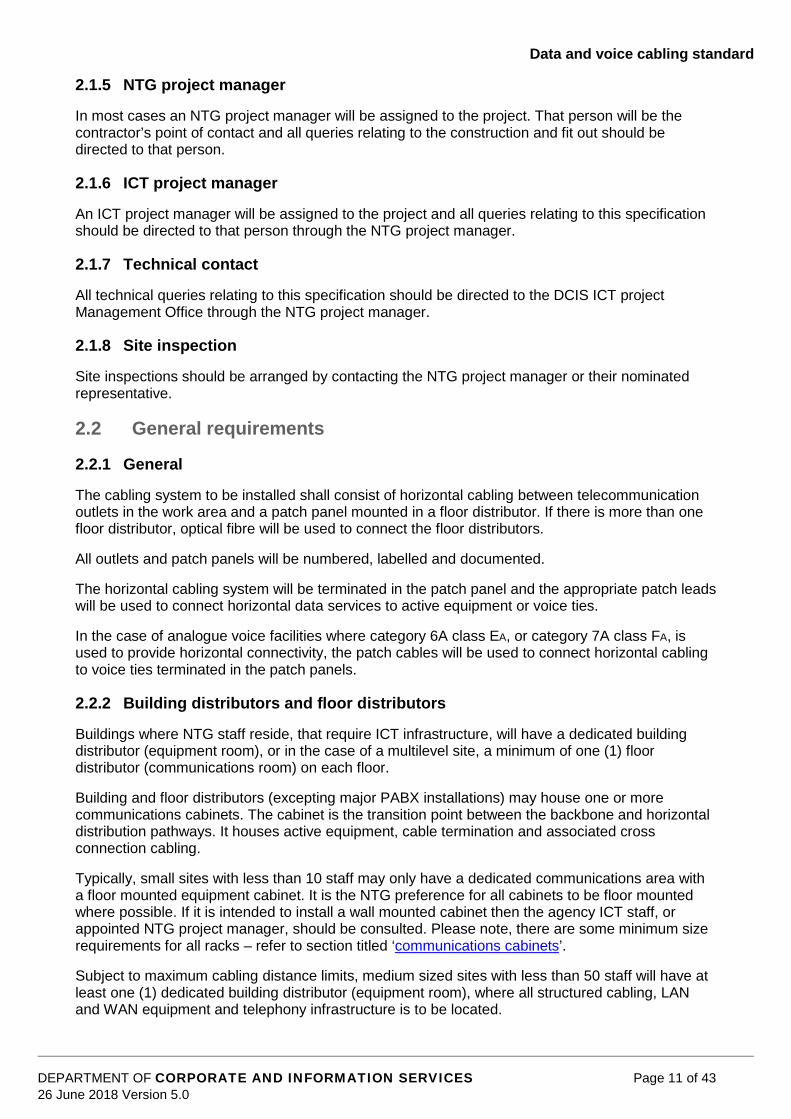
2.1.5 NTG project manager
In most cases an NTG project manager will be assigned to the project. That person will be thecontractor’s point of contact and all queries relating to the construction and fit out should bedirected to that person.
2.1.6 ICT project manager
An ICT project manager will be assigned to the project and all queries relating to this specificationshould be directed to that person through the NTG project manager.
2.1.7 Technical contact
All technical queries relating to this specification should be directed to the DCIS ICT projectManagement Office through the NTG project manager.
2.1.8 Site inspection
Site inspections should be arranged by contacting the NTG project manager or their nominatedrepresentative.
2.2 General requirements
2.2.1 General
The cabling system to be installed shall consist of horizontal cabling between telecommunicationoutlets in the work area and a patch panel mounted in a floor distributor. If there is more than onefloor distributor, optical fibre will be used to connect the floor distributors.
All outlets and patch panels will be numbered, labelled and documented.
The horizontal cabling system will be terminated in the patch panel and the appropriate patch leadswill be used to connect horizontal data services to active equipment or voice ties.
In the case of analogue voice facilities where category 6A class EA, or category 7A class FA, isused to provide horizontal connectivity, the patch cables will be used to connect horizontal cablingto voice ties terminated in the patch panels.
2.2.2 Building distributors and floor distributors
Buildings where NTG staff reside, that require ICT infrastructure, will have a dedicated buildingdistributor (equipment room), or in the case of a multilevel site, a minimum of one (1) floordistributor (communications room) on each floor.
Building and floor distributors (excepting major PABX installations) may house one or morecommunications cabinets. The cabinet is the transition point between the backbone and horizontaldistribution pathways. It houses active equipment, cable termination and associated crossconnection cabling.
Typically, small sites with less than 10 staff may only have a dedicated communications area witha floor mounted equipment cabinet. It is the NTG preference for all cabinets to be floor mountedwhere possible. If it is intended to install a wall mounted cabinet then the agency ICT staff, orappointed NTG project manager, should be consulted. Please note, there are some minimum sizerequirements for all racks – refer to section titled ‘communications cabinets’.
Subject to maximum cabling distance limits, medium sized sites with less than 50 staff will have atleast one (1) dedicated building distributor (equipment room), where all structured cabling, LANand WAN equipment and telephony infrastructure is to be located.

Data and voice cabling standard
DEPARTMENT OF CORPORATE AND INFORMATION SERVICES Page 12 of 4326 June 2018 Version 5.0
Large sites with greater than 50 staff, may have a requirement for multiple floor distributors(communications rooms), depending on the physical site characteristics e.g. multiple floors orbuildings or horizontal distances greater than 90 m within a building.
Floor distributor (cabinet room) locations and characteristics are subject to a number of constraints:
Location:
There must be a cabinet location within 90 m wiring distance of all current and potentialnetwork outlets.
The cabinet must be convenient for connection to the building backbone cabling i.e. adjacent orvery near to a vertical duct.
It must be accessible by trolley and provide reasonable space within or outside the area tounload and manoeuvre equipment.
It must be accessible by NTG service provider, contractor and NTG ICT staff 24 hours per day,seven days per week, and be positioned directly off a common area, e.g. corridor.
Cabinets, once installed, cannot be moved without consideration given to re-cabling the entirearea (floor or even building). The location must be in an area not subject to any plannedreconstruction.
Prohibited locations:
In ablution or toilet facilities, boiler, plant, machine rooms, or in areas subject to corrosivefumes or fluids, or excessive Electro Magnetic Interference (EMI).
In fire escape stairways.
Near automatic sprinklers, unless cabinet is protected from water.
In any area that is subject to flooding.
Within a cupboard containing a fire hose reel.
In a cupboard with no ventilation.
Size and inclusions:
Building and floor distribution rooms (communications rooms) will be sized by method ofcalculation.
There shall be 1.2 m clear space to the front and rear of the cabinet and 900 mm clear spaceon each side in a single cabinet situation.
Where multiple cabinets are installed they may be placed side by side but must maintain thesame clearances front and rear and to the outside of the nesting as for a single cabinet above.
Written approval to install a cabinet with one side adjacent to a wall must be made to the DCISICT Project Management Office, or agency ICT staff. This application must include a proposedroom layout.

Data and voice cabling standard
DEPARTMENT OF CORPORATE AND INFORMATION SERVICES Page 13 of 4326 June 2018 Version 5.0
Example of a single cabinet layout
Example of multiple cabinet layout

Data and voice cabling standard
DEPARTMENT OF CORPORATE AND INFORMATION SERVICES Page 14 of 4326 June 2018 Version 5.0
Example of a single wall mount cabinet layout
The space should not be shared with electrical installations such as switch boards unless thereis a minimum of 1 m separation. Only electrical installations that provide power to the cabinetwill be allowed. Any other unrelated service (e.g. plumbing) shall require written application tothe DCIS ICT project manager for approval.
Adequate separation between power and data cabling should be maintained at all times.
Unless otherwise approved, a dedicated 15 amp power outlet with threaded collar at the socketis to be provided, mounted externally adjacent to each cabinet, and suspended from the ceilingon a pendant mount. In the case of a wall mounted cabinet a dual 10 amp power outlet is to beinstalled on the wall alongside the cabinet.
Floor walls and ceilings should be finished to eliminate dust.
The floor must be level.
All penetrations are to be sealed as per fire regulations.
Provision should be considered for a security camera to be installed in the room; this willinclude data cabling to the designated location.
Pouring concrete around cables is not suitable as the water content may damage the cablesand will void the cabling warranty. Cabling passing through concrete must be run throughconduit cast in the concrete. Provide conduit of sufficient internal diameter to allow for 50%additional cabling to be run through the conduit.
Lighting adequate enough to enable detailed work within the cabinet.

Data and voice cabling standard
DEPARTMENT OF CORPORATE AND INFORMATION SERVICES Page 15 of 4326 June 2018 Version 5.0
In some cases where multiple active equipment and UPS are installed it may be necessary toprovide 24 x 7 air-conditioning for building distributor or floor distributor. It is recommended thatcontractors consult with NTG ICT staff or the ICT project manager to determine requirements.
If a separate air conditioning system is required then this needs to be provided with a dedicatedpower circuit. In some situations it may be necessary to protect and support the air conditioningsystem by UPS.
Building distributor and floor distributor rooms must have anti-static flooring, not carpeted, andideally have an aspirated smoke detector system installed. All walls / roof are to be sealed withpaint or other sealant type substance that minimises cement or concrete dust being introducedto the room.
Where building distributor and floor distributors have windows that are in direct sunlight thesewindows are to be blacked out.
Each building distributor and floor distributor must have a dedicated building earth cableinstalled in the room on an appropriately sized earth bar. All earthing conductors used shallhave green / yellow insulation, and comply with the requirements of Australian standards –AS/CA S009.
Building distributor and floor distributor sizing is dependent on:
the size of the site, or the number of staff at the site
quantity of structured cabling
quantity of cabinets to be installed
quantity of ICT equipment to be installed and
any agency specific ICT equipment e.g. BAS Servers to be installed.
Refer to AS/NZS 3084 for guidelines on sizing.
2.2.3 Communications cabinets
General
Communication cabinets are to be floor mounted unless otherwise approved by the ICT ProjectManagement Office.
Cabinets must conform to the following:
supplied by a recognised, reputable manufacturer with in-house warranty
a minimum of 45 RU 1000 mm in depth and 800 mm in width, unless otherwise directed, toensure NTG equipment can be installed correctly
a 150 mm minimum clearance between the face of the patch panels and the inside of theclosed door
where a smaller size communications cabinet has been approved, a minimum depth betweenthe rails of 600 mm is required, and is in addition to the clearance of 150 mm from the face ofthe patch panels to the inside of the closed door
secured to the floor to prevent tipping (i.e. bolted to floor), unless otherwise approved by theICT Project Management Office
Data and voice cabling standard
DEPARTMENT OF CORPORATE AND INFORMATION SERVICES Page 16 of 4326 June 2018 Version 5.0
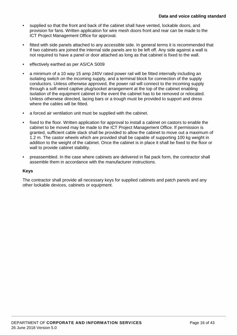
supplied so that the front and back of the cabinet shall have vented, lockable doors, andprovision for fans. Written application for wire mesh doors front and rear can be made to theICT Project Management Office for approval.
fitted with side panels attached to any accessible side. In general terms it is recommended thatif two cabinets are joined the internal side panels are to be left off. Any side against a wall isnot required to have a panel or door attached as long as that cabinet is fixed to the wall.
effectively earthed as per AS/CA S009
a minimum of a 10 way 15 amp 240V rated power rail will be fitted internally including anisolating switch on the incoming supply, and a terminal block for connection of the supplyconductors. Unless otherwise approved, the power rail will connect to the incoming supplythrough a soft wired captive plug/socket arrangement at the top of the cabinet enablingisolation of the equipment cabinet in the event the cabinet has to be removed or relocated.Unless otherwise directed, lacing bars or a trough must be provided to support and dresswhere the cables will be fitted.
a forced air ventilation unit must be supplied with the cabinet.
fixed to the floor. Written application for approval to install a cabinet on castors to enable thecabinet to be moved may be made to the ICT Project Management Office. If permission isgranted, sufficient cable slack shall be provided to allow the cabinet to move out a maximum of1.2 m. The castor wheels which are provided shall be capable of supporting 100 kg weight inaddition to the weight of the cabinet. Once the cabinet is in place it shall be fixed to the floor orwall to provide cabinet stability.
preassembled. In the case where cabinets are delivered in flat pack form, the contractor shallassemble them in accordance with the manufacturer instructions.
Keys
The contractor shall provide all necessary keys for supplied cabinets and patch panels and anyother lockable devices, cabinets or equipment.

Data and voice cabling standard
DEPARTMENT OF CORPORATE AND INFORMATION SERVICES Page 17 of 4326 June 2018 Version 5.0
2.2.4 Labelling of building and floor distribution rooms
Unless otherwise instructed, building and floor distribution rooms will be labelled according to theirNTG site code and location, i.e.:
100DCXGA
where 100DCX is the unique NTG building code (every NTG site has a unique identifier whichdefines the administrative region, and the name of the building. In this case 100 for Darwin andDCX identifying Charles Darwin Centre. Building codes are available from the ICT ProjectManagement Office) and
G is the location (G defining the ground floor in this case: options are B for basement, G forground, 1 for first floor, 2 for second floor, 3 for third floor, and so on) and
A being the first communications room on that floor (options are A for the first, B for thesecond, C for the third, and so on for the rest of the floor: A being the closest communicationsroom to the front door and Z being the furthest away from the front door).
Examples of communication room labelling
700AAP1B where 700 defines Alice Springs, AAP is Alice Plaza, 1 is the first floor, and B is thesecond communications room on that floor.
100DCX6A where 100 defines Darwin, DCX is Charles Darwin Centre, 6 is the sixth floor, and A isthe first communications room on that floor.
2.2.5 Labelling of communication cabinets
Unless otherwise instructed, communication cabinets will include the distribution room label and anumber; i.e.:
GA1
where GA is the communication rooms unique identifier and
1 is the cabinet number (cabinet numbers start at one and run for as many consecutivenumbers as there are cabinets; cabinets are numbered consecutively, one being closest to theentrance, and 999 being the furthest away from the entrance).
Examples of communication cabinet labelling
1B3 where 3 is the third cabinet in room 1B.
2A1 where 1 is the first cabinet in room 2A.
2.2.6 Labelling of wall outlets
Unless otherwise instructed, wall outlets will include the communications cabinet unique identifierand the wall outlet number. I.e.:
GA1-001
where GA1 is the cabinet identifier and
-001 is the wall outlet (wall outlet numbers start at -001 and run for as many consecutivenumbers as there are wall outlets on that floor; wall outlets are numbered where -001 is closestto the communications room and -999 being the furthest away from the communications room).

Data and voice cabling standard
DEPARTMENT OF CORPORATE AND INFORMATION SERVICES Page 18 of 4326 June 2018 Version 5.0
Examples of wall outlet labelling
GA2-028 where GA2 is the cabinet where that outlet is terminated and -028 is the patch panel portnumber in cabinet GA2.
2C2-125 identifies Level 2 communications room C cabinet number 2, and wall outlet -125.
Each work area data communications outlet plate shall be labelled using consecutive numbers.
Example of communications room, cabinet, and wall outlet labelling.
The designated order of multiple outlets on a single faceplate shall be from left to right and thenfrom top to bottom. Materials used for data communications outlet labels shall be durable orprotected from damage.
Designations shall be printed and not easily erased or altered. It shall be possible to changefaceplate designations by replacing the label.
2.2.7 Acceptable methods of labelling
Acceptable methods of labelling include:
printed plastic tape labels inserted into a recess in the faceplate intended for the purpose andfitted with a clear plastic cover. The mounted wall plate behind the face place shall have thedata outlet ID marked in indelible pen.
machine printed, self-adhesive labels adhered directly to the surface of the faceplate or cabinete.g. Traffolyte ®. This is the most suitable for communications cabinet labelling and haveprovided a photo as follows showing example of cabinet labelling:

Data and voice cabling standard
DEPARTMENT OF CORPORATE AND INFORMATION SERVICES Page 19 of 4326 June 2018 Version 5.0
lettering moulded, or heat embossed in the faceplate (for outlet designations only).
2.2.8 Unacceptable methods of labelling
Unacceptable methods of labelling include:
numbered plastic caps inserted over the flush plate fixing screws
embossed, self-adhesive plastic tape systems (such as Dymo ®)
press-in plastic number "dots" inserted into the flush plate with a single "dot" bearing allnumerals of the faceplate number
handwritten labels of any kind, including the use of paint pens
paper labels adhered directly to the surface of the faceplate
paper labels fitted in a recess without a durable protective cover.
2.2.9 Labelling patch panels
All positions on patch panels shall be labelled with the same designations as the correspondingwall outlets.
Patch Panel numbering shall commence with the lowest numbered port appearing at the top leftand proceed left to right, and then top to bottom.
Backbone cable numbering shall be designated according to the numbering scheme specified inthe Contract documents. The order of appearance of backbone cables on the patch panel shallcommence with the lowest numbered cable appearing at the top left and proceed left to right, andthen top to bottom.
2.2.10 Labelling optical fibre
The label used for each fibre core shall consist of five or six characters. The first two charactersshall indicate the building floor number (e.g. 00 represents ground floor, B1 represents basement1). The next character shall be a hyphen for read-ability purposes. The next character shall bealphabetic and will uniquely identify which fibre cable the core is part of (i.e. A = first cable etc.)The last character(s) shall be numeric, and shall identify the cable core.
For example: Core 03-A5 is the fifth core (5) in the first cable run (A) originating from the mainfibre patch panel and terminating at the fibre patch panel on the third floor (03).
2.2.11 Uninterrupted power supply (UPS)
Unless a Building UPS is installed to supply protected power to the floor distributors as part of theconstruction phase, Uninterrupted Power Supplies will be provided for NTG active equipment andinstallation will be arranged by the ICT project manager at the time equipment is being installedand commissioned.
The DCIS ICT Project Management Office should be included in all discussions regarding thesizing and distribution of Building UPS.
2.2.12 Horizontal cabling
Each work area data communications outlet shall be cabled to the patch panel without anyintermediate termination or jointing (unless the ICT project manager approves the use ofconsolidation points).
Bridges, taps and splices are not to be used.

Data and voice cabling standard
DEPARTMENT OF CORPORATE AND INFORMATION SERVICES Page 20 of 4326 June 2018 Version 5.0
All installed horizontal cable shall conform to the latest edition of AS/NZS 3080.
Existing cable requiring re-termination should be terminated using RJ45, or TERA style connector’sdependant on the cabling category installed.
A vertical duct shall be supplied and installed to carry cables from the ceiling space to theequipment cabinet, where required for neat appearance and mechanical protection of the cables.This duct shall have sufficient capacity for a 50% future increase in the number of cables.
All horizontal cabling runs shall be provided with not less than 600 mm of slack at each end. Wherecabling is run in ceilings, the slack shall be left in a loop on the catenary or cable tray directlyabove the drop points. Where cabling is run within stud walls, the slack shall be left in the cavitydirectly behind the faceplate. In all other cases, direction shall be obtained from the nominated ICTproject manager.
Cable bends shall maintain the minimum bend radius specified by the manufacturer. Deformationof the cables (e.g. pinching at points of support, when changing direction to pass through wallplates, etc.) shall be carefully avoided.
Only hook and loop ties, such as Velcro® brand, are to be used to bundle cables or supporthanging cable runs. Insulation tape and plastic cable ties are not permitted for cable bundling orcable support.
Where cable deformation is found to have occurred, it will be the contractor’s responsibility toreplace affected cabling. Penetration through fire rated walls, ceilings or floors shall be stopped, orfilled, using approved materials so as to maintain the existing fire rating. Installed cables shall notbe under tension.
2.2.13 Vertical cabling installation practices
Where cabling is required to be installed vertically, it shall be installed on Cable Trays and securedevery 300 mm using hook and loop fastening ties, such as Velcro® brand ties. Take due care tonot over tighten ties and place undue strain on the cabling infrastructure.
Where network cabling and power cabling run parallel they must maintain a segregation of at least300 mm, and 450 mm in the case of high voltage power cables, and only cross at right anglesusing adequate separation such as a conduit sleeve.
2.2.14 Work area telecommunication outlets and faceplates
Unless otherwise stated, each work area shall be provided with:
a white faceplate
RJ-45, or TERA style, female connector dependant on the nominated cable category
the connector shall be designed so that the incorrect insertion of a plug is not possible.
Unless otherwise specified all outlet plates shall be mounted horizontally.
Wherever possible, faceplates shall be flush mounted on walls or skirting duct.
Faceplates mounted in walls shall be fitted with a protective cover to prevent ingress of dust unlessthe design of the outlets renders this unnecessary.
Where faceplates cannot be flush mounted, the contractor shall supply and install suitablemounting blocks. Mounting blocks shall be of the same colour as the faceplates.
Faceplates shall be mounted at the same vertical height from the floor as adjacent or nearestpower outlets, or where these are not present, at the height specified by the ICT project manager.
Data and voice cabling standard
DEPARTMENT OF CORPORATE AND INFORMATION SERVICES Page 21 of 4326 June 2018 Version 5.0
Where faceplates are specified to be floor or service pole mounted, the contractor shall supply andinstall a suitable mounting box. Floor mounting boxes shall be fixed securely to the floor. The typeof mounting box proposed for use shall be submitted to the ICT project manager for approval priorto the commencement of work
2.2.15 Patch panel
Recognised good quality 24 port patch panels are to be provided. Where more than 24 ports arerequired, a number of 24 port modules shall be used.
Patch panels shall comply with the relevant standard for category 6A class EA and 7A installations.The terminations of the patch panels shall be suitable for terminating category 6A class EA and 7Acables. In general term patch panel categories should not be mixed and if this is intended it isrecommended to consult with agency ICT staff, or NTG project manager.
Cable management shall comply with the physical cable management clause within thisdocument.
The cabling shall connect directly to the patch panel using insulation displacement techniques.
2.2.16 Backbone cabling
Backbone networks shall consist of at least a single six core optical fibre connection from thebuilding distributor to each floor distributor. Larger sites may require a 12 core optical fibrebackbone, or multiple links.
If more than one LAN switch is required in an installation, they shall be linked by OM3 or OM4multi-mode optical fibre patch leads. Typically back bone optical fibre cables will be laser optimised(OM3/OM4) multi-mode or (OS2) single-mode.
2.2.17 Optical fibre
Optical fibre backbone cables shall be installed to meet the following minimum requirements:
all optical fibre cables shall conform to AS/NZS 3080 and shall be either OM3 or OM4 multi-mode, graded-index optical fibre
all optical fibre cable shall meet the minimum transmission performance specified inAS/NZS 3080
optical fibre cables shall be of a construction suitable for building riser applications. Slottedcore cables, for instance, are not acceptable.
OM3 and OM4 optical fibre cables shall be clearly marked as such to distinguish them from othercables and have suitable sheath identification.
All optical fibre cables shall be protected from breakage or stress through suitable protectiveducting or enclosures permanently anchored in position, as required. The protection level providedshall comply with AS/NZS 3013.
For major building installations, one building distributor shall be nominated as the main fibre patchpanel for the building. The network fibre backbone cables shall originate from this location to eachadditional fibre backbone node. Unless otherwise specified, all fibre optical cables being installedto provide a network backbone shall contain a minimum of six cores, with 12 core fibre beingrecommended.
All fibre cores shall be terminated. All termination enclosures shall be mounted in non-movablecabinets or securely fixed on structural walls within the building.

Data and voice cabling standard
DEPARTMENT OF CORPORATE AND INFORMATION SERVICES Page 22 of 4326 June 2018 Version 5.0
Within the building riser, the cable shall be attached to a cable tray anchored in position, and thecable shall be supported at points no greater than 300 mm apart. The fibre backbone can bemounted in the same cable tray as the copper cabling, but not in the same bundle. The fibre mustbe mounted separately.
For installations other than within major buildings, the location of all optical fibre network nodesshall be specifically indicated on the site plans.
2.3 Terminations
2.3.1 Horizontal cabling
The contractor shall be responsible for the termination of the horizontal cable on the work area,data communications outlets, and patch panels. Cable termination, pin assignments, pair allocationand colour coding shall conform to AS/NZS 3080, configuration T568A.
The location and configuration of the equipment cabinet, and the locations of the wall outletsrequired for the installation will be identified in the project documentation.
Cabinets are not to be installed by the contractor without the approval of the ICT project manager.
The tools utilised for terminating cables shall be of a type approved by the manufacturer for theconnectors used.
The cable twist rate shall be maintained as close as practical to the termination points on the walloutlets and the patch panel.
2.3.2 Optical fibre
All optical fibre circuits shall use the inter-connect methodology for the establishment of circuits.The connectors of equipment fly leads shall be connected directly to the connectors of thebackbone cable.
The performance of optical fibre circuit connections shall be in accordance with AS/NZS 3080.
All cables shall be neatly butted and stripped ensuring that fibres and jacketing are undamaged.
All optical fibres shall be either fusion spliced on to optical fibre pigtails which have been factorypre-terminated with type LC connectors, or terminated directly on site to type LC connectors. Theconnectors shall have ceramic ferrule connectors with a PC pre-radius ferrule installed by epoxyingthe connector onto the fibre end. (Crimp on type connectors are specifically not allowed).
These connectors shall sustain a minimum of 500 mating cycles as per AS/NZS 3080.
Where the contractor elects to use “on site” termination, the contractor shall provide test resultsthat prove the quality of the termination is as good as if it were made in the factory.
All connectors shall be supplied with protective caps fitted. The contractor must take steps duringthe installation to ensure that dust does not enter optic fibre cabling.
2.3.2.1 Optical fibre termination enclosures
Termination enclosures shall be of all metal construction with a fully enclosed compartment tohouse the cable entry, splice trays and bare fibre. This compartment shall be accessible via ascrewed or clipped panel.
Wall mounted enclosures shall be hinged to allow access to the rear of the patch panels. Rackmounted enclosures shall have a 150 mm recessed patch panel for exiting patch lead protectionand shall allow access to the splice trays from the front of the cabinet.

Data and voice cabling standard
DEPARTMENT OF CORPORATE AND INFORMATION SERVICES Page 23 of 4326 June 2018 Version 5.0
Optic fibre enclosures must be designed to anchor all optical fibre cables in place to preventmovement and resulting potential degradation of performance or damage to cables or terminations.
NOTE: Where there is active NTG Network equipment to be installed in this enclosure, please referto section titled ‘Communication cabinets’ for minimum rack size requirements.
2.3.3 Patch leads
2.3.3.1 Optical fibre
Patch leads shall be provided for interconnection between the fibre optic patch panel and theactive equipment located in the equipment cabinet. Each patch cable shall be:
600 mm, 1200 mm or 2000 mm of a single pair
fitted with LC type connectors at each end.
All optical fibre patch leads must be tested by the manufacturer to AS/NZS 3080.
Typically back bone optical fibre cables will be OM4 multi-mode or OS2 single mode unlessotherwise specified by the ICT project manager.
2.3.3.2 Fly leads and patch leads
Fly Leads shall be provided for interconnection between the wall outlets and user equipment.Patch leads shall be provided for interconnection between the patch panel and the activeequipment. Each lead shall be:
Category 6A class EA F/UTP – Cabling contractor to provide 100% of all leads. That is 100%patch leads and 100% fly leads. I.e. if the project requires 50 data outlets, then 50 patch leads and50 fly leads are required.
Slim line Category 6A F/UTP patch leads will be provided by the contractor.
Category 7A class FA – Cabling contractor to provide 100% of leads. That is 100% patch leadsand 100% fly leads. I.e. if the project requires 50 data outlets, then 50 patch leads and 50 fly leadsare required.
constructed of stranded conductors
fitted with RJ-45, or TERA connectors as required by the cabling standard
terminated with the pin assignments, pair allocation and colour coding specified in AS 3080,configuration T568A
tested by the manufacturer to the relevant standard.
The following is a guide to the lengths of required for patch and fly leads:
Length Patch Leads Fly leads0.5m 20%1.0m 35%1.5m 45%2.0m 55%3.0m 40%5.0m 5%
100% 100%

Data and voice cabling standard
DEPARTMENT OF CORPORATE AND INFORMATION SERVICES Page 24 of 4326 June 2018 Version 5.0
If contractor assembled leads are to be used, the tools and procedures used to fit the connectorsto the cable shall be approved by the manufacturers.
2.3.4 Integrated rear cable management
The patch panels shall provide integrated rear cable management for guiding cable to the IDCblock. This management facility shall provide cable bend radius guides to ensure minimum cablebend radius criteria (>four times cable diameter) is not exceeded during installation; and hook andloop fastening tape, such as Velcro® brand, to secure incoming cables without over-compressingthe cables, which could compromise the cable performance.
2.3.5 Physical cable management
A one RU horizontal cable manager is recommended below each patch panel and adequatevertical cable management, incorporating fingers and spools is essential.
The cable management panels should be mounted on the patching facility between every two rowsof connection ports. In this way, patch leads from every patch panel port are directed to the cablemanagement panels above or below the outlet so that at no time, even when fully populated,outlets are obscured by patch leads. Such a layout ensures the patching facility, when cablemanagement is properly utilised, does not go out of control and can be efficiently utilised for adds,moves and changes over the life of the cabling system.
To facilitate effective patching during the life of the cabling system, the cabinet shall be laid out forminimal clutter and the shortest reasonable route for patch cords.
In a single cabinet installation, the patch panels terminating the horizontal cabling should becentrally located in the cabinet. Active equipment such as LAN switches, if accommodated in thecabinet, should be mounted above the horizontal cable patch panels. In the case where there aremore than 144 outlets switches may be mounted above and below the patch panel. System patchpanels such as for 3X/AS400 or terminal based systems, if utilised, should be mounted above theactive equipment.
Where analogue voice service cabling is routed to the IDF, the patch panels terminating thesecables should be installed below the horizontal cabling patch panels. Where multiple cabinets areto be utilised the same layout principle should be adopted horizontally.
2.3.6 Cabling topology
The topology of the horizontal sub-system is star connected with each cable being a maximum of90 m. Where a horizontal cabling cannot be established within the 90 m limitation, a second IDFshall be established to install a second horizontal sub-system to meet the specification. Thelocation of a second or subsequent IDF shall be to the ICT project manager’s approval.
2.3.7 Equipment cabinet layout
The contractor shall install the cabinets in the position indicated by the project documentation. Thecontractor shall install the patch panels, shelves and data cabling in the cabinets.

Data and voice cabling standard
DEPARTMENT OF CORPORATE AND INFORMATION SERVICES Page 25 of 4326 June 2018 Version 5.0
Unless otherwise specified, the layout of all cabinets shall normally conform to the following typicalexamples:
Example of 45 Rack Unit (45RU) Floor Standing Cabinet Layout

Data and voice cabling standard
DEPARTMENT OF CORPORATE AND INFORMATION SERVICES Page 26 of 4326 June 2018 Version 5.0
Example of 12 Rack Unit (RU) Wall Mounted Cabinet Layout
Typically the horizontal patch panels should be located midway down the cabinet depending uponthe space requirements for optic fibre terminations and active equipment. Cable managementshould be provided for each 24 port patch panel.
All installed cabinets shall be earthed.
2.3.8 Ducting, cable trays and service poles
2.3.8.1 Work area
Wherever practical, cables shall be run in existing wall, ceiling or floor voids.
In certain circumstances, ducting or conduit may be required to provide an acceptable appearanceand to provide mechanical protection of horizontal cabling. Typical examples include:
to carry workstation cabling around skirtings to the work area data communications outletswhere these outlets are required to be mounted on solid external and internal walls
to carry workstation cabling from the ceiling space to skirting ducts in room corners andadjacent to door frames where practical to minimise the length of cabling runs
to carry workstation cabling from the ceiling space to the work area data communicationsoutlets on columns and where skirting duct runs would be impractical
to carry workstation cabling from the ceiling to the top of partition walls.
Vertical ducting runs shall have a physical separation barrier when next to conduits carrying mainspower. Their colour shall be compatible with the background wall or column colour. The duct shallbe surface mounted.
All ducting shall be of sufficient cross section to carry the number of cables required, plus at leasttwo additional cables to allow for future changes, including those installations where only one cableis required.
Where the contractor deems additional ducting to be required for an installation, details shall besubmitted to the ICT project manager for approval prior to commencing such work.
Service poles may be required to provide network facilities in an open office environment. Thecontractor shall provide a minimum of two channel segregated service poles.
All cabling to be installed in external cavity walls shall be installed in conduit.

Data and voice cabling standard
DEPARTMENT OF CORPORATE AND INFORMATION SERVICES Page 27 of 4326 June 2018 Version 5.0
2.3.8.2 Ceiling space
All new cabling in ceiling spaces shall be installed in accordance with AS/NZS 3084 andAS/CA S009.
2.3.8.3 Catenary cable support system
Where wire mesh cable tray supports for cabling are not available, catenary cables shall beinstalled. All catenary cables shall be 2.5 mm PVC coated, multi strand steel cable fixed to thebuilding structure at a maximum of 3 m intervals. Fixings should be at irregular intervals to preventperformance degradation due to in-phase noise build up. The cable should be securely fixed to thebuilding structure using M8 x 25 mm Dyna ® bolts or similar. M6 x 25 mm Dyna ® bolts shall beused for the secondary support fixings.
Cables shall be secured to the catenary support system using Velcro ® style tie wraps at amaximum of 300 mm centres. Insulation tape may be used to facilitate installation of the bundles,however permanent fixing must be completed using Velcro ® style tie wraps.
Cable shall be in a maximum of 24 cables per bundle. Each catenary shall support a maximum of48 cables, i.e. two bundles of 24 cables.
Each bundle of cables shall be individually supported from the catenary cable using Velcro ® styleties wraps.
2.3.9 Building riser
Cabling contractors are responsible for the correct replacement of fire retardant material whenwork in risers is completed.
Contractors must provide written certification to the NT Government Property Management branchthat appropriate material has been installed as per manufacturer’s specifications. Contractors mustbe accredited installers in order to complete this work or must arrange for a suitably qualifiedinstaller to complete the installation and provide the necessary certification. Failure to provide therequired certification may have implications concerning liability in the case of fire or otheremergency situations.
Cabling contractors are responsible for ensuring that building risers are maintained in a tidy andclean state during installation, and any refuse material is disposed of in an appropriate manner.
All cabling installed into risers is to be fixed to wire mesh cable trays at a minimum of 300 mmcentres by Velcro ® style ties with appropriate separation from AC power as per AS/CA S009.
2.4 Installation of underground fibre
2.4.1 High level design
A high level design, including the proposed route, for the network extension will be provided by theICT Project Management Office.
2.4.2 Supply and installation of conduit
All conduit used in the installation shall comply with the following:
use 50mm poly pipe class 9 PE communications conduit, unless otherwise directed
external building entry conduits will consist of a 32 mm GI conduit and comply with AS2053.2
all conduits must enter the end of a pit only
no conduit is to be installed at the base of a pit
Data and voice cabling standard
DEPARTMENT OF CORPORATE AND INFORMATION SERVICES Page 28 of 4326 June 2018 Version 5.0
large sweeping bends are to be used for change of direction, for 50 mm conduit a minimumradius of 800 mm is required
smaller bends may only to be used on building entry, for 50 mm conduit a minimum radius of300 mm is required.
2.4.3 Supply and installation of pits
The contractor shall ensure that:
P5 or P6 rectangular communications pits are used
all pits must be fitted with NTG approved locking lids
pits must not be installed more than 250 m apart
the location of pits will comply with the approved high-level design
pits must be installed level
pits inside fence boundaries are to be finished to the NTG project manager’s requirements
pits outside fence boundaries are to be finished to Local Government requirements
carrier approval is obtained where a carrier service is being provided externally
pits are to be installed on common property boundaries where practical
pits are not to be installed in locations where driveways, or vehicle parking areas may beconstructed at a later date
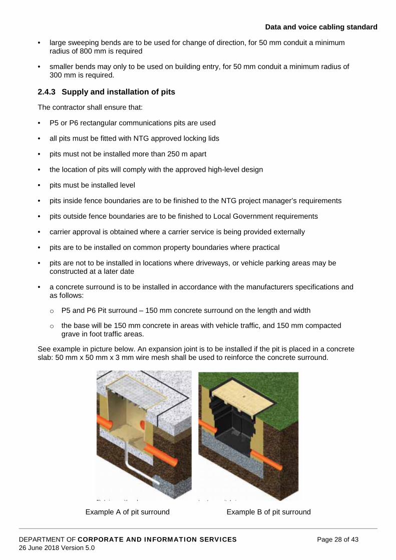
a concrete surround is to be installed in accordance with the manufacturers specifications andas follows:
o P5 and P6 Pit surround – 150 mm concrete surround on the length and width
o the base will be 150 mm concrete in areas with vehicle traffic, and 150 mm compactedgrave in foot traffic areas.
See example in picture below. An expansion joint is to be installed if the pit is placed in a concreteslab: 50 mm x 50 mm x 3 mm wire mesh shall be used to reinforce the concrete surround.
Example A of pit surround Example B of pit surround

Data and voice cabling standard
DEPARTMENT OF CORPORATE AND INFORMATION SERVICES Page 29 of 4326 June 2018 Version 5.0
2.4.4 Backfill and reinstatement of excavation
Bedding material
Bedding material only shall be used around conduit.
Conduit ends, including bends at each pillar location and elsewhere, shall be securely supported inposition during placement and compaction of bedding material.
All conduits shall be separated by compacted bedding material and spacers used to maintainseparation between conduits shall be removed prior to bedding material compaction.
Bedding material shall be placed in layers not exceeding 100 mm, packed under and around thesides to avoid the formation of air pockets beneath pipes or collars, and finished at a level of50 mm minimum above conduits.
Backfilling generally
Backfilling is to be completed as soon as practicable after the installation and audit of conduits intrenches.
Polymeric cable protection cover shall be installed where required. Orange caution tape to advise“Warning Communication Cable Below” shall be installed where shown on the applicable drawingand backfilling continued.
Trenches in areas other than footpaths and roads e.g. private property, shall be backfilled in looselayers not exceeding 250 mm and compacted to achieve 95% of standard maximum dry densityobtained in accordance with AS1289 5.5.1.
In areas such as roadways and access tracks 98% of standard maximum dry density is required.Rock, sharp objects or any other material that could damage conduit is not permitted in backfillwithin 200 mm of the conduit.
2.4.5 Reinstatement of surfaces
Permanent reinstatement of surfaces shall be carried out as soon as practical after backfilling, thesurface level and finish shall match as near as possible the surface prior to excavation, and be tothe satisfaction of the NTG project manager.
Additionally the reinstatement of concrete driveways and slabs shall include the drilling anddoweling of adjoining concrete surfaces where practical during the reinstatement work.
2.4.6 Care of optical fibre cable
Optical fibre cable shall be protected from damage at all stages of handling and installation.
In particular excessive bending or crushing shall be avoided. Cable ends shall be suitably sealed toprevent the ingress of water. Cables shall be handled using only suitable equipment and in such amanner as to prevent deformation or damage.
Conductors shall be protected from immersion in water or contamination with foreign materials.
Vehicles shall not be driven over optical fibres on the ground.
Factors that can cause possible fibre damage, if they are excessive, are as follows:
tension
twisting
bending

Data and voice cabling standard
DEPARTMENT OF CORPORATE AND INFORMATION SERVICES Page 30 of 4326 June 2018 Version 5.0
crushing
vibration.
2.4.7 Pre-installation testing
Procedure
The attenuation of all optical fibres shall be checked at the time of delivery by the contractor.
Attenuation data will be compared with that included on the certified test reports supplied from themanufacturer.
After completion of this test, the contractor shall seal the cable against water or dust entry.
This practice will be observed after each subsequent test, and prior to splicing.
Plastic caps shall be fitted using adhesive plastic tape to seal the ends.
Splicing and termination
The contractor shall carry out the fibre terminations by fusion splicing methods such that the signalattenuation at each joint is as per the specifications outlined in AS/NZS 3080.
The average loss for all joints in any one fibre from substation to substation shall not exceed0.12 dB.
The fibre shall be arranged in the termination boxes with loops contained within trays in an orderlyand consistent identifiable pattern with sufficient slack to allow re-jointing without resorting to extraoptical fibre cable.
The contractor shall be responsible for sealing the termination boxes such that they are water tight.
The boxes and coiled fibre cable shall be structurally secured in a neat and tidy manner. Materialsused for securing the fibre cable and the terminal boxes shall be durable to give the requiredmaintenance free design life of 50 years.
Post installation testing
The attenuation of all fibres shall be checked by the contractor after installation of the optical fibrecable and splicing of the fibres.
The contractor shall be responsible for all work and materials required to remedy any fibre defectsthat occurred during installation or for the remaking of joints that do not meet specificationrequirements.
2.4.8 ‘As Constructed’ drawings
Prior to the issue of a completion notice the contractor will supply ‘As Constructed’drawings for the civil works which will include;
actual placement of the conduit infrastructure
distance of infrastructure between pits
actual placement of the pit
type/size of pit
pit number/Labels
Data and voice cabling standard
DEPARTMENT OF CORPORATE AND INFORMATION SERVICES Page 31 of 4326 June 2018 Version 5.0
bore logs.
All ‘As Constructed’ drawings must be returned to the NTG project manager within 10 days ofpractical completion, and registered with NTLIS for inclusion in dial before you dig (Call 1100 orwww.1100.com.au).
2.5 Testing
2.5.1 Horizontal cabling
All cables shall be tested for Ethernet operation by the contractor according to a formal test planand as per AS/NZS IEC 61935. The test plan shall be submitted to the ICT project manager forapproval prior to the commencement of testing and must confirm the operation of the cablinginstallation.
A complete set of test results shall be provided to the ICT project manager as part of thedocumentation.
The contractor must use recognised industry standard test equipment.
2.5.2 Backbone optical fibre
The following shall be the minimum testing requirements for the backbone optical fibre cabling:
100% of optical fibre shall be tested for loss and uniformity of transmission characteristicsusing a recording optical TDR (time domain reflector). The measurement method shall be inaccordance with AS/NZS ISO/IEC 14763.3. The test shall be performed from each end unlessan additional tail fibre is used such that both ends of entire fibre length under test is observablein the OTDR display. A copy of the test results shall be included with the documentation,including the instrument measurement scale factors etc.
Connector loss should be measured for optical fibre fly leads.
Acceptable loss measurements are as defined in AS/NZS 3080.
The test methods to be employed for optical fibre cable testing should comply with the relevantstandard for optical fibre testing.
2.5.3 Documentation
The NTG will provide to the contractor copies of the primary site plan(s) at the time of an order forinstallation, alteration, or additions to the data network.
Upon completion of the work at each site the following documentation shall provide to the NTGproject manager and the ICT project manager:
an updated site plan showing the physical location and designation of each cable route, cableducts and cable trays, marked up on the supplied drawing(s)
one copy of these drawings shall be provided to the project supervisor, and a second copyshall be left in a suitable holder mounted in the appropriate data communications closet orcommunications room
cable run list of backbone cable from start to end location
copies of all test results
update any local service records as required

Data and voice cabling standard
DEPARTMENT OF CORPORATE AND INFORMATION SERVICES Page 32 of 4326 June 2018 Version 5.0
completed forms necessary to meet the regulations pertaining to power installation in theNorthern Territory
documentation of all cabling components used, including manufacturer's part number
any manuals supplied with the installed equipment and
any keys or codes for any lockable device.

Data and voice cabling standard
DEPARTMENT OF CORPORATE AND INFORMATION SERVICES Page 33 of 4326 June 2018 Version 5.0
2.6 StandardsIn general, the requirements of the following standards shall be met.
2.6.1 Australian/New Zealand standards
Cabling materials and practice shall comply with the requirements of the latest edition oramendment of the following Australian standards.
Standard number Standard titleAS/NZS 3000 Electrical installations Australian/NZ wiring rules.AS/NZS 3080 Integrated communications cabling systems for commercial premises.AS/NZS 3013 Electrical installations – classification of fire and mechanical
performance of wiring systems.AS/NZS 3084 Telecommunications installations – Telecommunications pathways
and spaces for commercial buildings.AS/NZS 3085.1 Telecommunications Installations – Administration of communications
Cabling Systems.AS/NZS IEC 61935.1 Testing of balanced communications cabling in accordance with
ISO/IEC 11801- Installed cabling.AS/NZS IEC 61935.2 Testing of balanced communications cabling in accordance with
ISO/IEC 11801- Patch cords and work area.AS/NZS IEC 61935.2 Telecommunications installations – Advanced testing for optical fibre
cabling.AS/NZS 60950 Safety of information technology equipment.AS/NZS 4117 Surge protective devices for telecommunications applications.AS/CA S003 Customer switching, multiplexing and ancillary equipment for
connection to a telecommunications Network.AS/CA S008 Requirements for authorised cabling products.AS/CA S009 Installation requirements for customer cabling (wiring rules).
2.6.2 ACMA Technical standards
Standard number Standard titleACA TS001-1997 Safety requirements for customer equipment (expires 1 July 2004).ACA TS002-1998 Telecommunications technical standard (customer equipment and
customer cabling).ACMA – CPR Cabling provider rules (latest edition).
2.6.3 International Standards
Standard number Standard titleIEEE 802.3 Carrier sense, multiple access with collision detection (CSMA/CD)
access method and physical layer specifications (latest edition).ISO/IEC 11801 Information technology – Generic cabling for customer premises.

Data and voice cabling standard
DEPARTMENT OF CORPORATE AND INFORMATION SERVICES Page 34 of 4326 June 2018 Version 5.0
3 Additional cabling system installation and testspecifications
3.1 Separation from electrical supplyAny AC voltage over 42.4 volts AC (peak) and any DC voltage over 60 volts is considered to behazardous. Safe extra low voltages (SELV) and telecommunications network voltages (TNV) arenot considered hazardous.
High voltage (HV) power is considered extremely hazardous.
Ensure separation of all data communications cables and fittings from low voltage cables by acontinuous solid barrier or 100 mm spacing. This segregation is to be fully maintained at all times,especially at entry or exit points, crossovers, junctions and all accessories and fittings. Where acontinuous barrier is employed, it shall be either durable insulating material or metal. If it is metal,the barrier shall be bonded to the building protective earthing system.
Data communications cable is to be physically separated from HV cables by a minimum distanceof 450 mm. Avoid long parallel runs of data communications cables and other higher voltagecables.
3.2 Quality and performance expectationsThe installation phase of the project is the culmination of the planning and design phases, and assuch it is important that the installer to have documented work practices and quality assuranceprocedures to include the total range of works within the project.
Connection of equipment to a public telecommunications network shall be completed by personnelcomplying with local telecommunications carrier licensing requirements.
During the installation activities, records must be kept of all items installed, including reference tocable pathways used, final location, identity of cables and equipment. The presentation of all ofthese records will provide the "as constructed" basis for all future reference to the installation.
The cabling shall be installed in accordance with manufacturer’s installation instructions. Themanufacturer’s certified installer will ensure that the manufacturer’s specifications for the cablesmeet the transmission characteristics detailed in this document and/or the relevant Australianstandards.
All installed cables, termination boxes, distribution panels and wall outlets shall be marked andnumbered in accordance with the relevant standards to the naming convention provided by theclient. This marking and numbering shall be used during the creation of all installation records anddocumentation.
The testing and certification of installed cabling, interconnection hardware and patch leads shallcomply with the relevant standards.
In particular the following tests should be carried out and the results documented and maintainedto form part of the "As Constructed" documentation:
test all of the copper cable installation for termination and twisted pair integrity, includingcontinuity, polarity, pin-assignment and colour codes
perform visual inspections to ensure that each pair of wires remain twisted as close as possibleto the termination point, to maintain the impedance and minimise attenuation losses

Data and voice cabling standard
DEPARTMENT OF CORPORATE AND INFORMATION SERVICES Page 35 of 4326 June 2018 Version 5.0
test the cabling installed for:
o alien cross-talk (ANEXT)
o near end cross-talk (NEXT)
o PowerSum near end cross-talk (PSNEXT)
o equal level far end cross-talk (ELFEXT)
o PowerSum equal level far end cross-talk (PSELFEXT)
o insertion loss
o return loss
o delay and
o delay skew.
To ensure the installed cable complies with category 6A class EA, or category 7A class FA channelperformance criteria, matching patch cords from the same manufacturer must be used.
An allocation of time should be allowed for the consulting engineer or the client's representative towitness the certification process and to perform some sample tests of the installed cabling system.The amount of time is outlined in the scope of works, however there should be at least to (2)Witness Points;
once cabling has commenced and prior to ceiling tiles being installed, at completion of the cabling, and before testing and building finalisation work.
The documentation required at the completion of the installation phases shall contain all of thefollowing information, together with any other information the installer has acquired during theinstallation:
“as constructed” documentation, showing total cabling and connection installed, utilising floorspace plans and cable record sheets. This documentation must show all cables and outletsincorporating the full numbering and marking convention supplied
cabling test results and certification information, identified by cable, connection and numberingconvention, necessary for all cables.
The installers shall provide a full statement of "workmanship warranty" applicable to the totalinstallation, and shall state their agreement to investigate and restore any failed part of theinstallation when requested to do so by the client.
During the period of the project, all aspects of the installation will be monitored for progress andcompletion in accordance with the project plans provided by the client.
A representative of the client will be appointed to perform the tasks of project management. Thisindividual will liaise at all times with the installers and will be responsible for the acceptance of theinstallation at the time of completion.
The process of acceptance will have occurred when the installer has produced the fulldocumentation package, and when the ICT project manager is satisfied that all of the works havebeen completed and all required information has been provided.
The installer should recognise the importance of notification to the NTG appointed project managerof any problem or item of disruption to the installation schedule. Every effort must be made to keepwithin the timetables provided by the client.

Data and voice cabling standard
DEPARTMENT OF CORPORATE AND INFORMATION SERVICES Page 36 of 4326 June 2018 Version 5.0
All components of the cabling system should be sourced from one manufacturer to ensure minimalimpedance mismatch and best possible return loss performance and to guarantee the performancefrom end-to-end.
The cabling system should operate without introducing or being affected by electromagneticradiation from other sources. Maintaining segregation from other services or screening (metalconduit) are the only methods to achieve acceptable immunity.
F/UTP systems must be provided with appropriate F/UTP patch leads. UTP patch leads are notto be used on F/UTP systems.
3.3 Ancillary considerationsUpon completion of final engineering drawings, the contractor will provide to the ICT projectmanager:
the building and floor distribution diagrams including cable routing, position of all componentsand apparatus and detail of the cabinet layout and labelling plan
all horizontal cable routes will be detailed on a plan to the general contractor and an approvedlabelling plan for all work areas
all cable trays, conduit and catenary installation plans.
3.4 Entrance facility (EF) or building distributorThis facility requires:
minimum floor space of 3.4 m x 2.6 m, within a room dedicated for the purpose, or some otheralternative location suitable for outlet distribution
UPS power for communications cabinet and emergency lighting, size to be evaluated
cabling access to building risers via ceiling space or adjacent wall where possible
security access control to the room, where possible
air conditioning/ventilation to be provided sufficient for equipment and personnel 24 houroperational heat load
remote alarm or monitor for system failure or over temperature, 24 hour operation
ceiling lighting switched within the room, plus emergency lighting in the event of building powerfailure
normal building power to selected outlets
fire safety system
access door sized to ensure equipment installation.
3.5 CertificationThe entire cabling system components and installation shall be covered by warrantees providedthe manufacturer and the installer. Certification shall provide a minimum 20 year product warranty,system warranty, and application assurance on applications for the passive element of the cablingsystem.
The system warranty shall commit the manufacturer to ensure that any standards sanctionedapplication introduced over the installed cabling system will function normally, over a period of a

Data and voice cabling standard
DEPARTMENT OF CORPORATE AND INFORMATION SERVICES Page 37 of 4326 June 2018 Version 5.0
minimum of 20 years from the date of certification. If any problems are experienced during theintroduction of such applications, the manufacturer shall provide the necessary support for thecabling system for the application to be activated at no cost to the user.
The product warranty shall commit the manufacturer to rectify any passive cabling component thatmay fail during a 20 year period from the commissioning of the cabling system, and the installer torectify any installation errors for the same time period.
The installer shall demonstrate their certified installer status and submit a copy of their certificationdocument, identifying the individual(s) commissioned to provide the certification of the installation.
The installation shall comprise of components in the data stream from only one manufacturer toensure optimal end-to-end electrical and mechanical integrity.
The entire installation shall be 100% tested, with all results documented before acceptance of theinstallation is granted.
Every circuit should be tested end-to-end including all patch leads and fly leads and the resultsdocumented in accordance with the labelling convention supplied by the client.
Allowance must be made for the ICT project manager to be present at the certification process andcomplete spot checks.
All documentation on the certification process is to be presented in both hard copy and on compactdisc and included in the "As Constructed" documentation to the ICT project manager.
4 Additional requirements for category 7A class FA
4.1 GeneralThis section describes the additional system requirements to be met in the proposals of thetelecommunications cabling vendors to secure under contract all materials, design, engineering,installation, supervision, and training services for the structured cabling system.
4.1.1 Site configuration
Consolidation points are not permitted with category 7A class FA cabling.
Catenary cable support systems or wire mesh cable tray will be used to support cabling in theceiling space and cabling will not be supported by the use of ceiling hangers or allowed to rest onthe suspended ceilings.
No power supply cables are to be laid on or in catenary or cable trays, and can only cross catenaryor cable trays with the required physical separation.
4.1.2 Installer requirements
The installer shall, at a minimum, possess the following qualifications:
have a minimum of five years business experience
demonstrate satisfaction of sound financial condition and can be adequately bonded andinsured if the project deems necessary
possess those licenses/permits required to perform telecommunications installations in thespecified jurisdiction
the cabling contractor is required to be the cabling manufacturer’s certified Installer.
Data and voice cabling standard
DEPARTMENT OF CORPORATE AND INFORMATION SERVICES Page 38 of 4326 June 2018 Version 5.0
The installer must employ personnel knowledgeable in local, state, and national codes andregulations. All work shall comply with the latest revision of the codes or regulations. When conflictexists between local or national codes or regulations, the most stringent codes or regulations shallbe followed.
The installer must possess current liability insurance certificates.
4.1.3 Required installer training
The installer shall be fully conversant and capable in the cabling of low voltage applications suchas, but not limited to data, voice, and imaging network systems.
The installer shall at a minimum possess the following:
personnel trained and certified in the design of the manufacturer’s cabling system
personnel trained and certified to install the manufacturer’s cabling system
the designer and installer shall show proof of current certification to the design and installationof the manufacturer’s cabling system
provide references detailing past successful completion of the type(s) of installations providedin this specification
personnel trained and certified in category 7 termination and testing techniques
personnel must have experience in the use of approved testing equipment
personnel trained in the installation of pathways and support for housing horizontal andbackbone cabling.
4.1.4 Manufacturer quality and product substitutions
All telecommunications connecting hardware and cable must be manufactured by an ISO 9001Certified Manufacturer.
All products must meet the technical requirements listed in this document. Any products notmeetings these requirements will not be considered.
4.1.5 Outlets
All category 7A class FA information outlets designed for termination of four-pair balanced twisted-pair category 7A class FA copper cables must possess the following characteristics at theminimum:
meet or exceed AS/NZS 3080 category 7A class FA electrical performance specifications
exceeds AS/NZS 3080 and EN5O173 requirements for transfer impedance and shieldeffectiveness
be Underwriters Laboratories 1863 and Canadian Telecommunications Standards C22.2certified.

Data and voice cabling standard
DEPARTMENT OF CORPORATE AND INFORMATION SERVICES Page 39 of 4326 June 2018 Version 5.0
4.1.6 Fly leads and patch leads
All category 7A class FA modular equipment leads shall conform to the flowing minimumperformance standards:
be 100% transmission tested with laboratory grade network analysers for proper performance
be available with black, white, red, yellow, blue or green strain relief boots and ivory colouredjacket
be available in standard lengths of one, two, three and five meters with custom lengthsavailable upon request, and fitted with TERA style connector and RJ45 at the other end withthe exception of backbone patch leads which should have TERA style at each end
meet or exceed AS/NZS 3080 category 7A class FA electrical performance specifications
100% patch leads and fly leads are to be supplied by the contractor at the completion ofinstallation for each data outlet installed.
4.2 Installation
4.2.1 Site survey
Prior to placing any cable pathways or cable, the contractor shall survey the site to determine jobconditions will not impose any obstructions that would interfere with the safe and satisfactoryplacement of the cables. Approval from the NTG appointed project manager must be sought toremove any obstructions.
4.2.2 Horizontal cable routing
All horizontal cable routing shall conform to the following:
all horizontal cables, regardless of media type, shall not exceed 90 m from thetelecommunications outlets in the work area to the horizontal cross connect
the combined length of jumpers, or patch cords and equipment cables in thetelecommunications room and the work area should not exceed 10 m
horizontal pathways shall be installed or selected such that the minimum bend radius ofhorizontal cables is kept within manufacturer specifications both during and after installation
in open ceiling cabling, cable supports shall be provided by means that is structurallyindependent of the suspended ceiling, its framework, or supports (these supports shall bespaced no more than 1.5 m apart)
each run of balanced twisted-pair cable between the horizontal portions of the cross-connect inthe telecommunication closet and the information outlet shall not contain splices
in a false ceiling environment, a minimum of 75 mm shall be observed between the cablesupports and the false ceiling
continuous conduit runs installed by the contractor should not exceed 30.5 m or contain morethan two 90 degree bends without utilising appropriately sized pull boxes
all horizontal pathways shall be designed, installed and grounded to meet applicable local andnational building and electrical codes
the number of horizontal cables placed in a cable support or pathway shall be limited to anumber of cables that will not cause a geometric shape of the cables

Data and voice cabling standard
DEPARTMENT OF CORPORATE AND INFORMATION SERVICES Page 40 of 4326 June 2018 Version 5.0
maximum conduit pathway capacity shall not exceed a 40% fill; however, perimeter andfurniture fill is limited to 60% fill to allow for move and changes
horizontal distribution cables shall not be exposed in the work area or other locations withpublic access.
4.2.3 Pulling tension
The maximum cable pulling tensions shall not exceed 110N.
4.2.4 Bend radius
The maximum cable bend radii shall not exceed manufacturer’s specifications.
4.2.5 Slack
In the work area, a minimum of 300 mm should be left for balanced twisted-pair cables, while onemetre is left for fibre cables.
In telecommunications rooms a minimum of three metres of slack should be left for all cable types.This slack must be neatly managed on trays or other support types.
4.2.6 Grounding
All grounding/earthing and bonding shall be done to applicable standards.
4.2.7 Testing
Testing of all newly installed cable channels shall be performed prior to system cutover.
4.2.7.1 Category 7A class FA testing
Category 7A class FA cabling shall comply with the following:
All category 7A class FA field-testing shall be performed with an approved category 7A class FAbalanced twisted-pair field test device.
All installed category 7A class FA channels shall perform equal to or better than the minimumrequirements as specified by the manufacturer.
Category 7A class FA balanced twisted-pair horizontal and backbone cables, whose lengthdoes not exceed 90 m (295 ft.) for the basic link, and 100 m (328 ft.) for the channel shall be100% tested according to AS/NZS 3080. Test parameters include wire map plus ScTP shieldcontinuity (when present), length, NEXT loss (pair-to-pair), NEXT loss (power sum), ELFEXTloss (pair-to-pair), ELFEXT loss (power sum), return loss, insertion loss, propagation delay anddelay skew.
4.2.7.2 Test equipment criteria
Test equipment shall comply with the following:
all balanced twisted-pair field testers shall be factory calibrated each calendar year by the fieldtest equipment manufacturer as stipulated by the manuals provided with the field test unit; thecalibration certificate shall be provided for review prior to the start of testing
auto test settings provided in the field test equipment for testing the installed cabling shall beset to the default parameters
test settings selected from options provided in the field testers shall be compatible with theinstalled cable under test.

Data and voice cabling standard
DEPARTMENT OF CORPORATE AND INFORMATION SERVICES Page 41 of 4326 June 2018 Version 5.0
4.3 WarrantyEither a basic link or channel model configuration may be applied to the horizontal and / orbackbone sub-systems of the structured cabling system. Applications assurance is only applied toa channel model configuration.
4.3.1 System warranty
A minimum of a 20 year warranty for the category 7A class FA structured cabling system shall beprovided for an end-to-end channel model installation which covers applications assurance, cable,connecting hardware and the labour cost for the repair or replacement thereof.
4.3.2 Applications supported
Existing and future applications supported for a channel model warranty include those approved bythe Institute of electronic and Electrical Engineers (IEEE), the asynchronous transfer mode (ATM)Forum, the American National Standards Institute (ANSI) or the International Organization ofStandards (ISO) that specify compatibility with the cable referenced herein.
5 Requirements for wireless networking
5.1 GeneralIt may be a requirement of the project to install wireless access points (WAPs). The ICT projectmanager will arrange for the supply and commissioning of the WAPs.
WAPs are powered by power over Ethernet (PoE). A dedicated mains power outlet is not requiredat WAP locations.
5.1.1 Wireless survey
The ICT project manager will commission a wireless survey when the building site is at the stagewhere all the internal walls are constructed and prior to painting. This survey will determine theinstallation location for the WAP.
5.1.2 WAP hardware installation
The ICT project manager will provide the contractor with WAP mounting brackets which thecontractor shall install at the locations identified by the wireless survey.
When installing the WAP brackets the contractor’s cabling installer shall:
unless otherwise specified, each WAP location install have a single category 6A class EA, orcategory 7A class FA, block mounted data outlet in the ceiling at the identified location. Dataoutlet labelling will be in accordance with the requirements of this document; in some casesdual outlets may be required and it is recommended that contractors engage agency ICT staffor ICT project manager in order to determine requirements. A label should be placed on theceiling grid adjacent to the WAP, and on the mounting block in the ceiling, clearlyidentifying the data outlet.
the data outlet(s) shall be installed on the underside of the ceiling slab above suspendedceiling and in a location that is easily accessible from below using step ladders
a 3 m category 6A class EA, category 7A class FA, fly-lead shall be plugged into the data outletand left suspended above the ceiling grid; this fly-lead will be labelled at both ends (within50 mm) of the data jack with the data outlet number it is connected to – the label must beattached in such a way that it is secure and fully visible

Data and voice cabling standard
DEPARTMENT OF CORPORATE AND INFORMATION SERVICES Page 42 of 4326 June 2018 Version 5.0
the WAP mounting brackets shall be fitted onto the underside of a suspended ceiling tile gridas directed by the ICT project manager
the contractor shall locate the free end of 3 m fly-lead and route it to the WAP bracket and thenthrough the edge of the ceiling tile to a distance of no more than 300 mm.
Notwithstanding the above, if a data outlet is approved for installation on the ceiling tile frame, thenthe shortest fly lead to suit the application may be used. The ICT project manager may giveapproval and advice on fly lead length.
The NTG will install the WAP to the brackets and connect the fly-lead to the WAP.
6 Requirements for closed circuit television (CCTV)
6.1 GeneralServer rooms may require internal monitoring by CCTV. The contract documentation will identify ifa camera is required. The ICT project manager can also provide input.
6.1.1 CCTV hardware installation
The CCTV location will be nominated by the ICT project manager.
The CCTV camera will require a single category 6A class EA, or category 7A class FA, blockmounted data outlet provided by the contractor.
NTG will utilise the services of a CCTV sub-contractor for the installation and commissioning of thecamera.
CCTV cameras are powered by power over Ethernet (PoE). A dedicated mains power outlet is notrequired at CCTV locations.

Data and voice cabling standard
DEPARTMENT OF CORPORATE AND INFORMATION SERVICES Page 43 of 4326 June 2018 Version 5.0
This page intentionally left blank