Embed Size (px)
DESCRIPTION
Gives introduction to data and network communication from book by Miller.
Citation preview
Introduction to data and network communications
History of telecommunications
Data communication systems
Data communications links
Some hardware facts
Analog and digital data
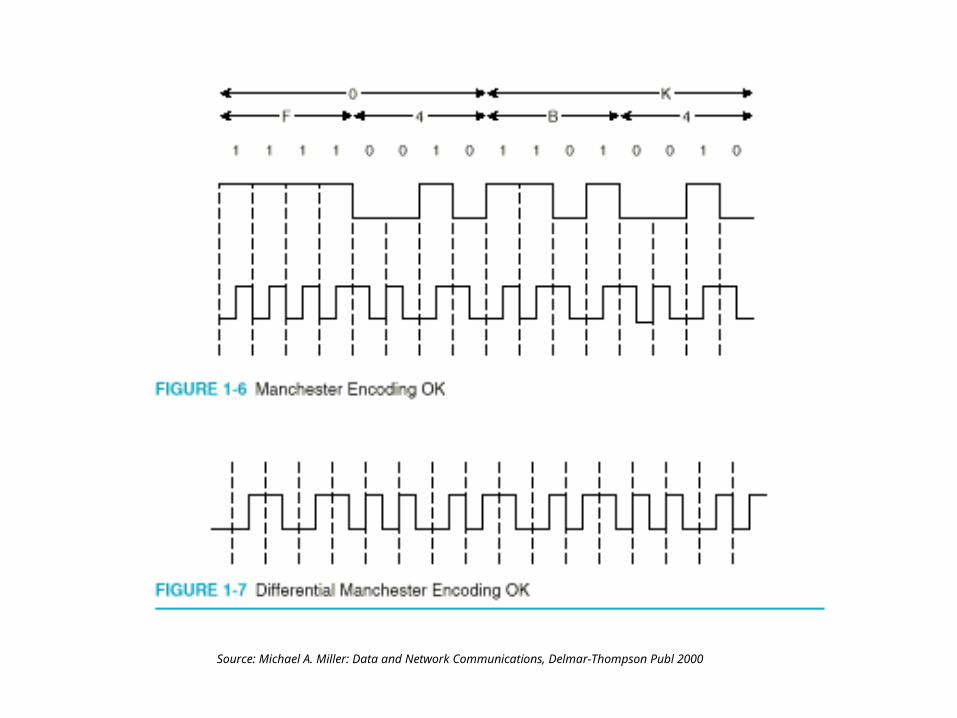
Codes: binary, ASCII
Digital data rates
Data formats
Required textbook for this course: Michael A. Miller: Data and Network Communications, Delmar-Thompson Learning, 2000
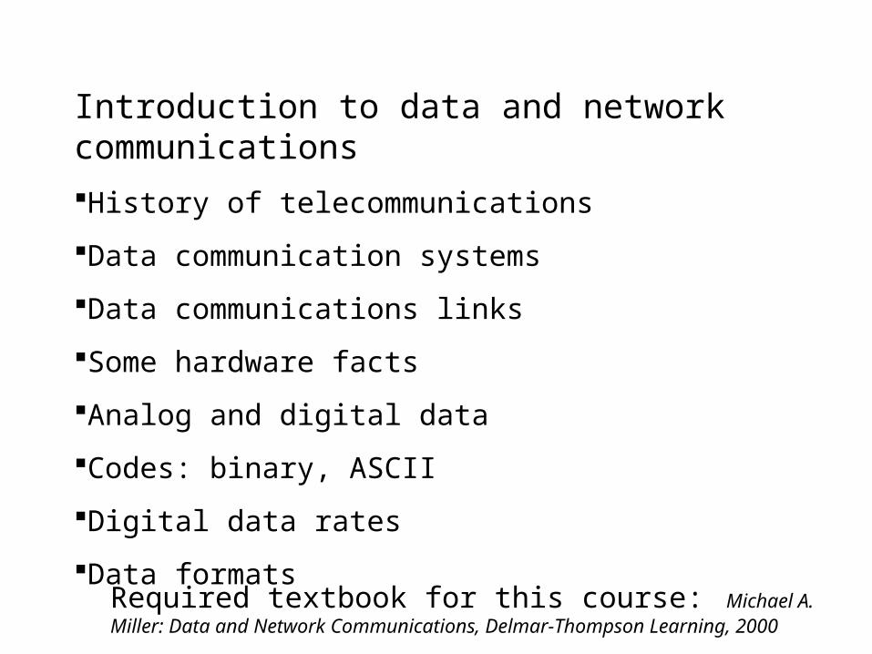
Milestones in history of telecom
• 1832 Morse code
• 1874 teletype
• 1876 Telephone
• 1881 Long distance line Boston-Providence
• 1898 Marconi wireless telegraph
• 1921 first radio broadcast
• 1934 FCC formed
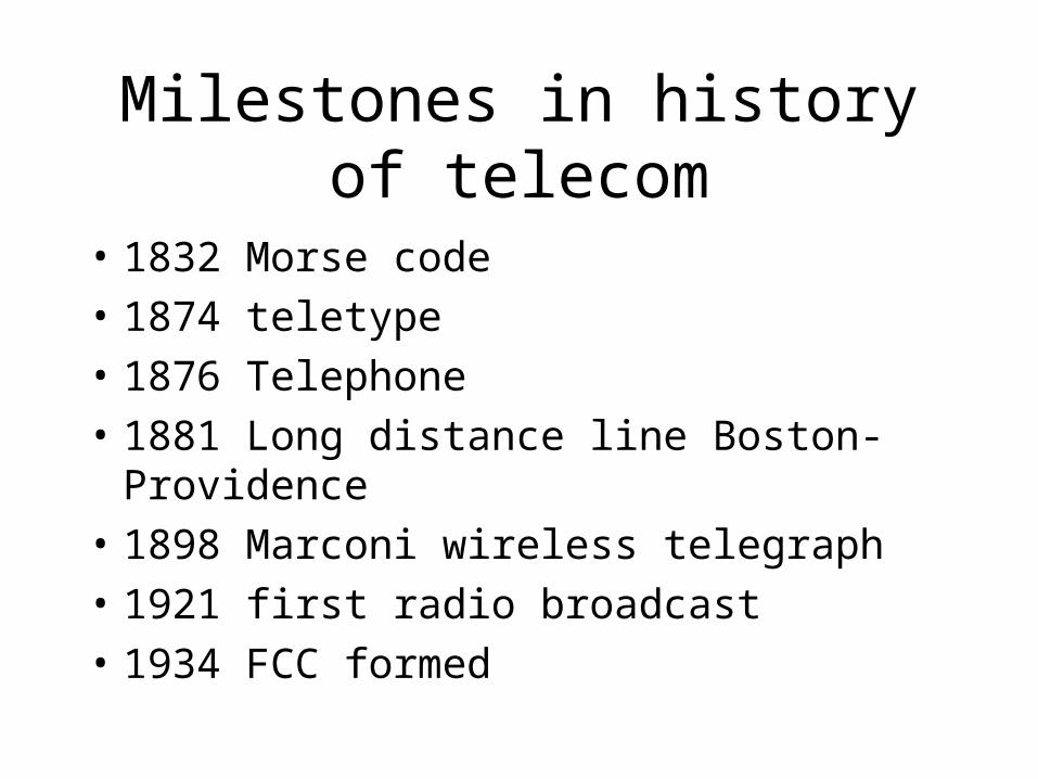
Milestones continued
• 1940 first computers: ENIAC, MARK I, II
• 1947 transistor invented
• 1956 TDM – time division multiplexing
• 1958 first coast-to-coast microwave
• 1959 first integrated circuits
• 1965 Intelsat 1
• 1966 fiber optic cable
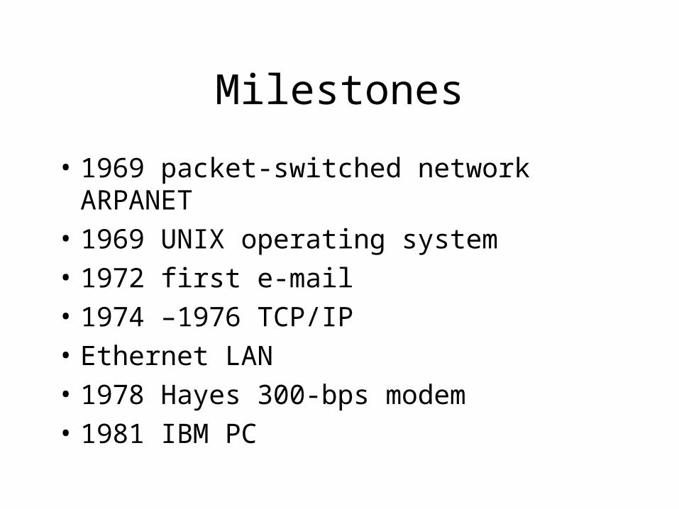
Milestones
• 1969 packet-switched network ARPANET
• 1969 UNIX operating system
• 1972 first e-mail
• 1974 –1976 TCP/IP
• Ethernet LAN
• 1978 Hayes 300-bps modem
• 1981 IBM PC
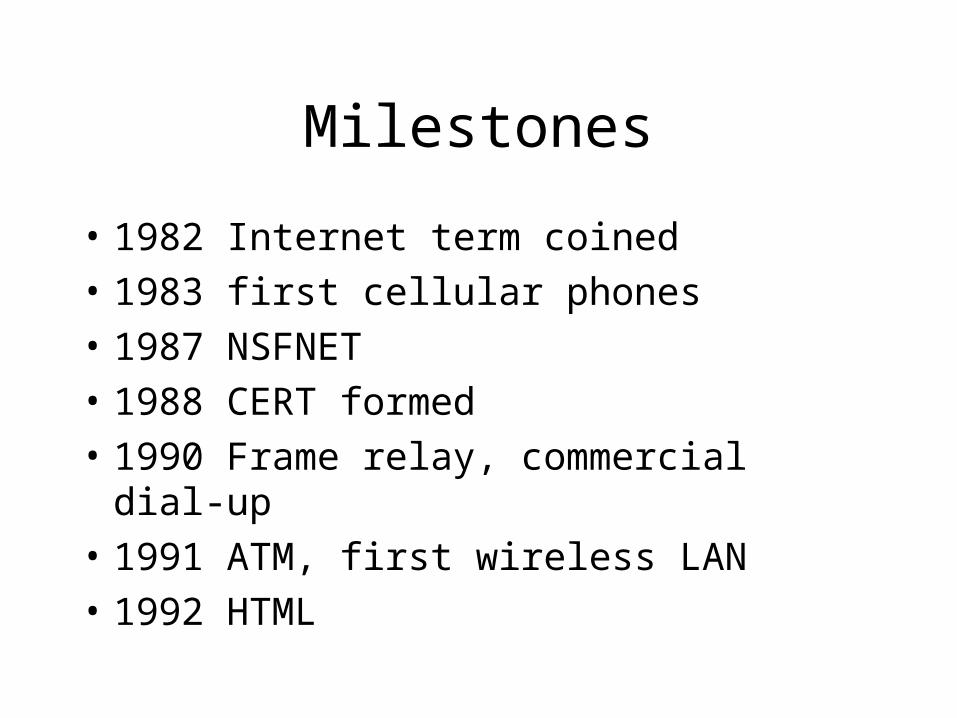
Milestones
• 1982 Internet term coined
• 1983 first cellular phones
• 1987 NSFNET
• 1988 CERT formed
• 1990 Frame relay, commercial dial-up
• 1991 ATM, first wireless LAN
• 1992 HTML
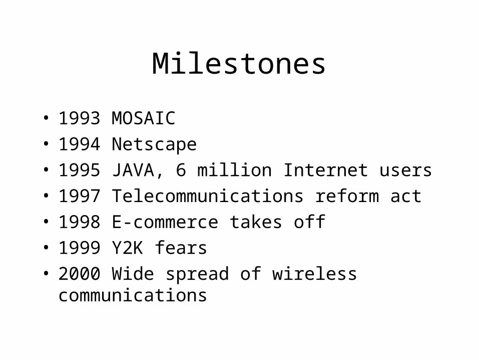
Milestones
• 1993 MOSAIC• 1994 Netscape• 1995 JAVA, 6 million Internet users• 1997 Telecommunications reform act• 1998 E-commerce takes off• 1999 Y2K fears• 2000 Wide spread of wireless communications
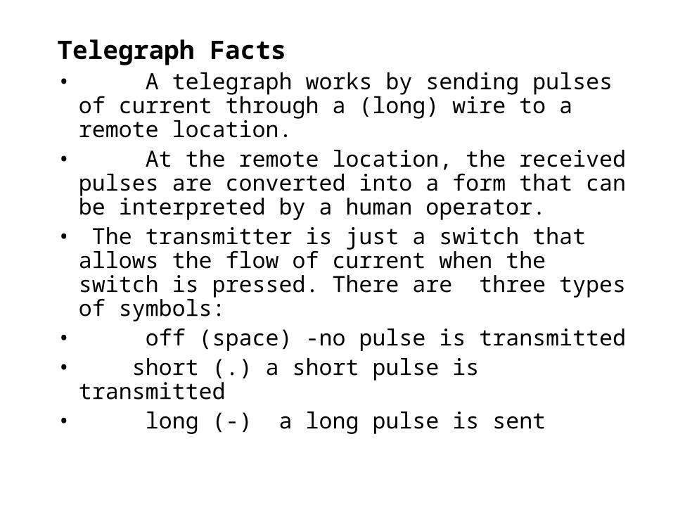
Telegraph Facts • A telegraph works by sending pulses of current
through a (long) wire to a remote location. • At the remote location, the received pulses are
converted into a form that can be interpreted by a human operator.
• The transmitter is just a switch that allows the flow of current when the switch is pressed. There are three types of symbols:
• off (space) -no pulse is transmitted• short (.) a short pulse is transmitted • long (-) a long pulse is sent
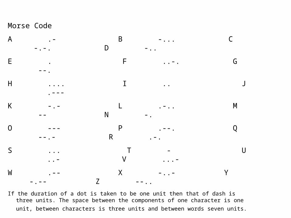
Morse Code
A .- B -... C -.-. D -..
E . F ..-. G --.
H .... I .. J .---
K -.- L .-.. M -- N -.
O --- P .--. Q --.- R .-.
S ... T - U ..- V ...-
W .-- X -..- Y -.-- Z --..
If the duration of a dot is taken to be one unit then that of dash is three units. The space between the components of one character is one unit, between characters is three
units and between words seven units.
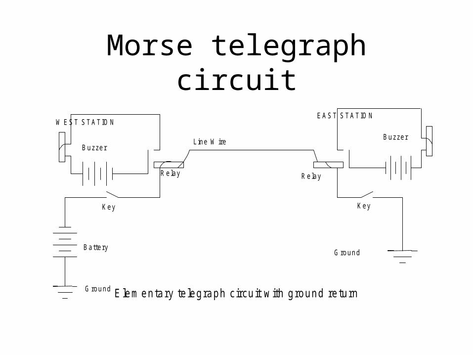
Morse telegraph circuit
K ey K ey
B attery
G round
G round
Line W ireB uzzer
R elay R elay
B uzzer
W E S T S TAT IO NE A ST STA TIO N
E lem entary te legraph circu it w ith ground return
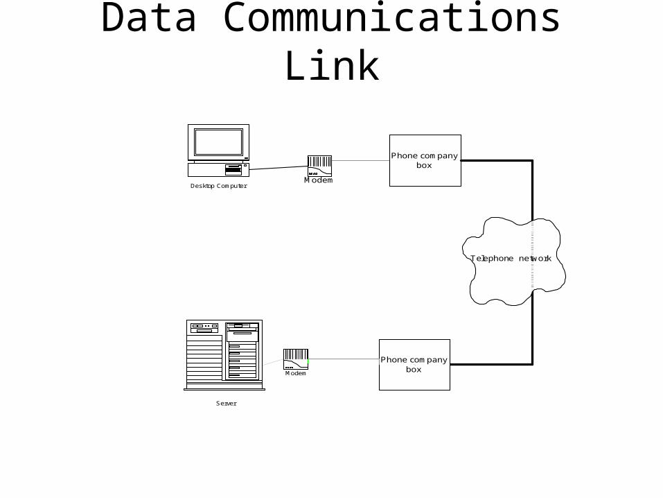
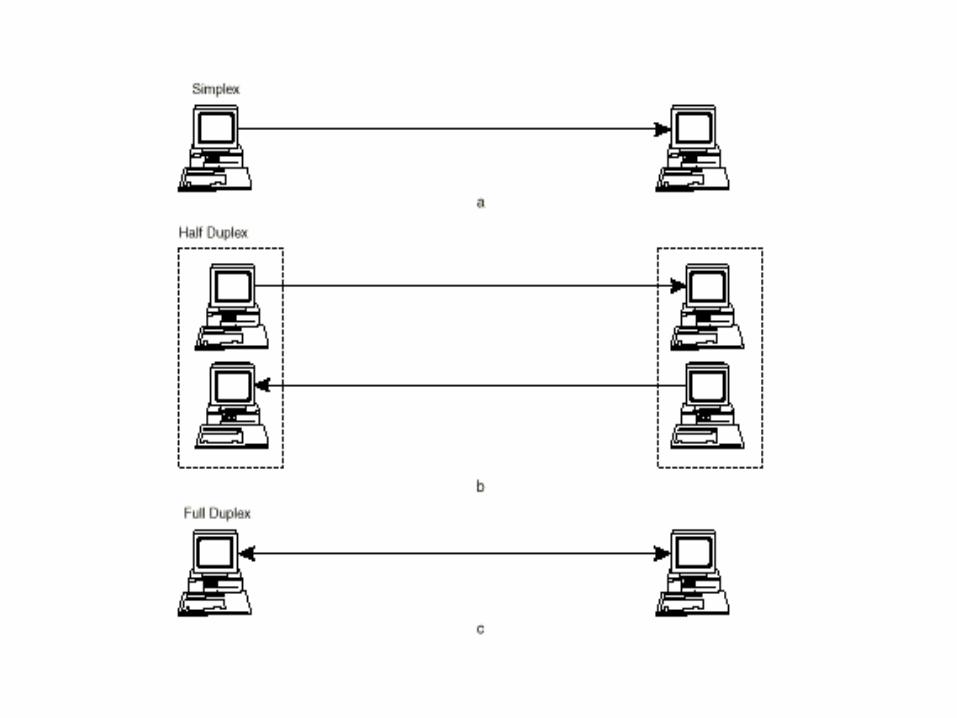
Data Communications Link
Desktop Computer
Phone company box
Phone company box Modem
Server
Modem
Telephone network
Source: Michael A. Miller: Data and Network Communications, Delmar-Thompson Publ 2000
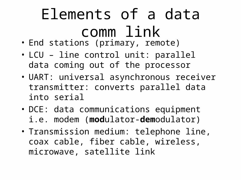
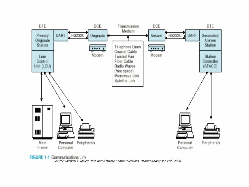
Elements of a data comm link• End stations (primary, remote)• LCU – line control unit: parallel data coming out
of the processor• UART: universal asynchronous receiver
transmitter: converts parallel data into serial• DCE: data communications equipment i.e. modem
(modulator-demodulator)• Transmission medium: telephone line, coax cable,
fiber cable, wireless, microwave, satellite link
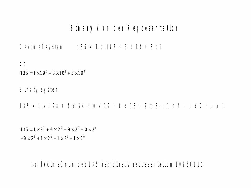
B i n a r y N u m b e r R e p r e s e n t a t i o n
D e c i m a l s y s t e m 1 3 5 = 1 x 1 0 0 + 3 x 1 0 + 5 x 1 o r 13 5 1 10 3 10 5 102 1 0 B i n a r y s y s t e m 1 3 5 = 1 x 1 2 8 + 0 x 6 4 + 0 x 3 2 + 0 x 1 6 + 0 x 8 + 1 x 4 + 1 x 2 + 1 x 1 1 3 5 1 2 0 2 0 2 0 2
0 2 1 2 1 2 1 2
7 6 5 4
3 2 1 0
s o d e c i m a l n u m b e r 1 3 5 h a s b i n a r y r e p r e s e n t a t i o n 1 0 0 0 0 1 1 1
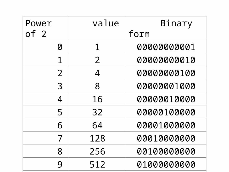
Power of 2 value Binary form
0 1 00000000001
1 2 00000000010
2 4 00000000100
3 8 00000001000
4 16 00000010000
5 32 00000100000
6 64 00001000000
7 128 00010000000
8 256 00100000000
9 512 01000000000
10 1024 10000000000
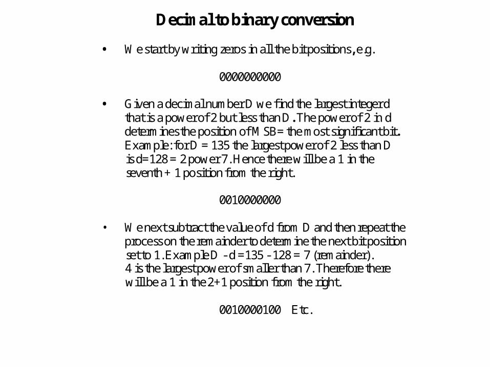
Decimal to binary conversion
• We start by writing zeros in all the bit positions, e.g.
0000000000
• Given a decimal number D we find the largest integer dthat is a power of 2 but less than D. The power of 2 in ddetermines the position of MSB= the most significant bit.Example: for D = 135 the largest power of 2 less than Dis d=128 = 2 power 7. Hence there will be a 1 in theseventh + 1 position from the right.
0010000000
• We next subtract the value of d from D and then repeat theprocess on the remainder to determine the next bit positionset to 1. Example D - d =135 - 128 = 7 (remainder).4 is the largest power of smaller than 7. Therefore therewill be a 1 in the 2+1 position from the right.
0010000100 Etc.
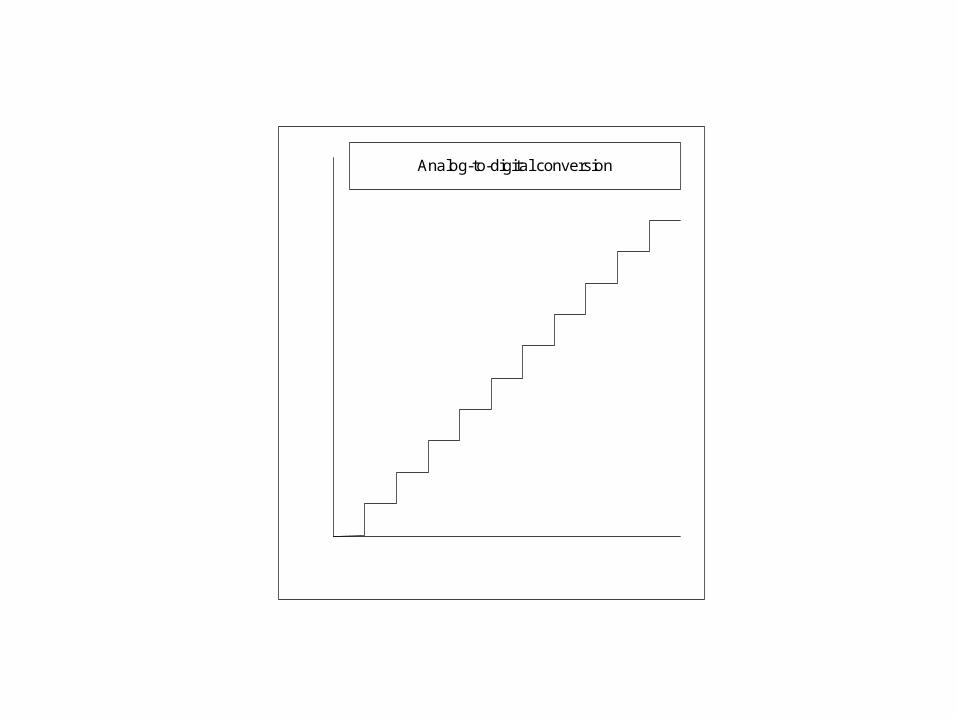
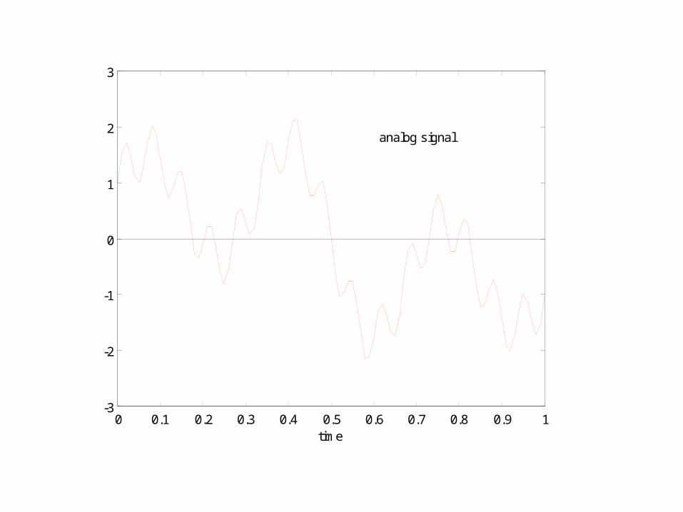
Analog-to-digital conversion
0 0.1 0.2 0.3 0.4 0.5 0.6 0.7 0.8 0.9 1-3
-2
-1
0
1
2
3
analog signal
time
0 0.1 0.2 0.3 0.4 0.5 0.6 0.7 0.8 0.9 1-3
-2
-1
0
1
2
3
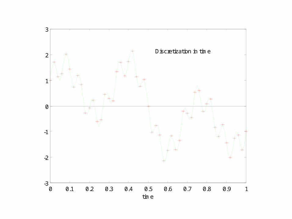
time
Discretization in time

0 0.1 0.2 0.3 0.4 0.5 0.6 0.7 0.8 0.9 1-3
-2
-1
0
1
2
3
analog signal
time
discretized
0 0.1 0.2 0.3 0.4 0.5 0.6 0.7 0.8 0.9 1-3
-2
-1
0
1
2
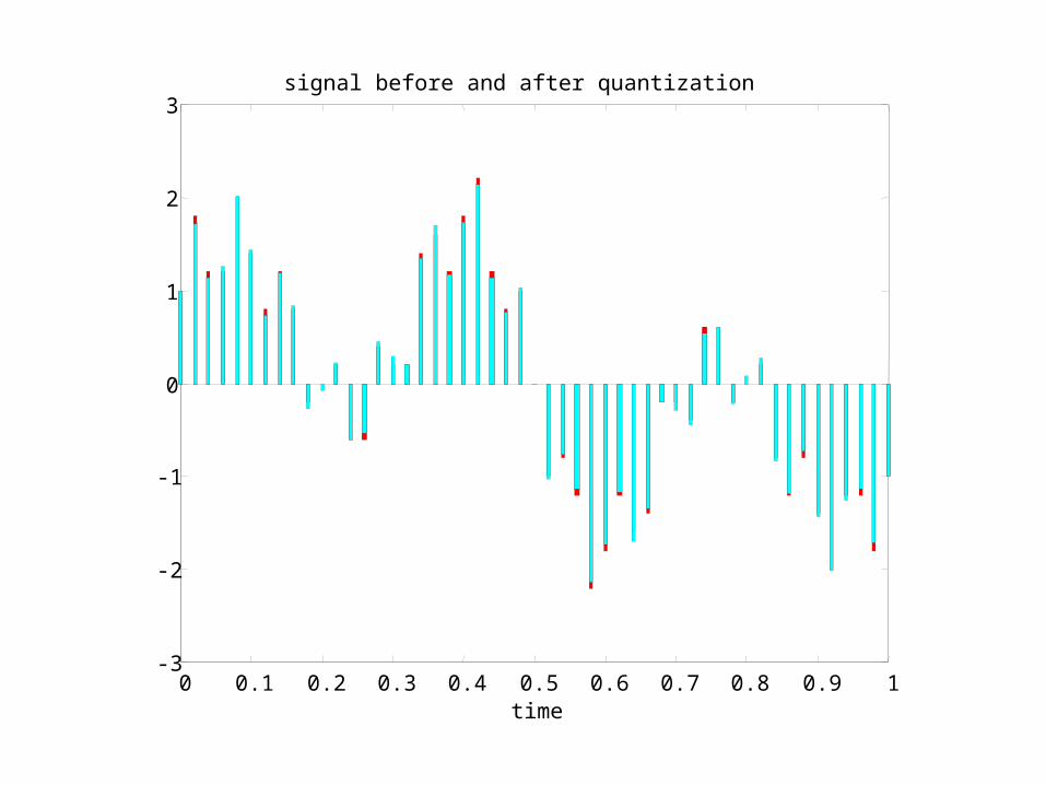
3signal before and after quantization
time
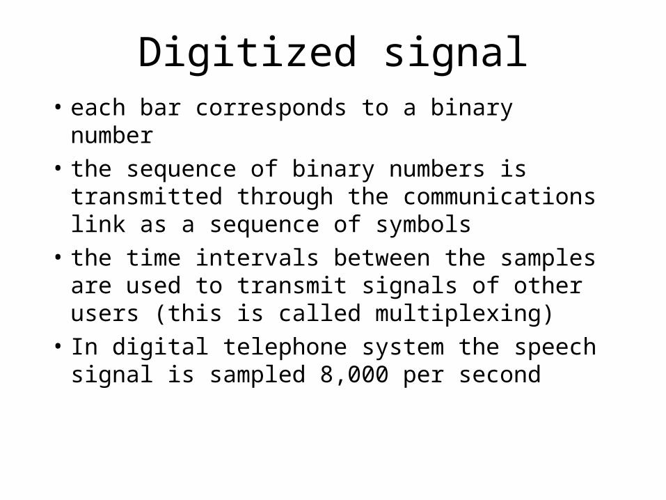
Digitized signal• each bar corresponds to a binary number
• the sequence of binary numbers is transmitted through the communications link as a sequence of symbols
• the time intervals between the samples are used to transmit signals of other users (this is called multiplexing)
• In digital telephone system the speech signal is sampled 8,000 per second
Frequency, bandwidth
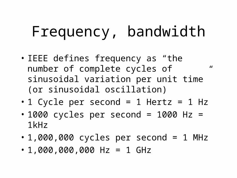
• IEEE defines frequency as “the number of complete cycles of sinusoidal variation per unit time” (or sinusoidal oscillation)
• 1 Cycle per second = 1 Hertz = 1 Hz
• 1000 cycles per second = 1000 Hz = 1kHz
• 1,000,000 cycles per second = 1 MHz
• 1,000,000,000 Hz = 1 GHz
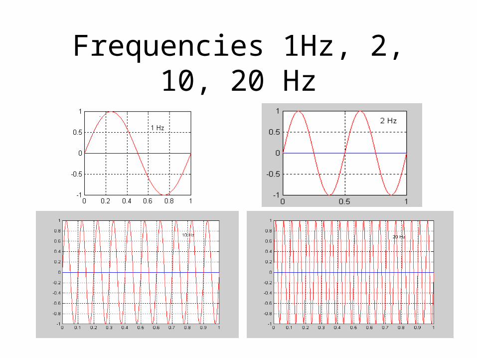
Frequencies 1Hz, 2, 10, 20 Hz
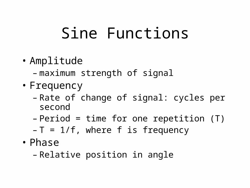
Sine Functions
• Amplitude – maximum strength of signal
• Frequency– Rate of change of signal: cycles per second– Period = time for one repetition (T)– T = 1/f, where f is frequency
• Phase – Relative position in angle
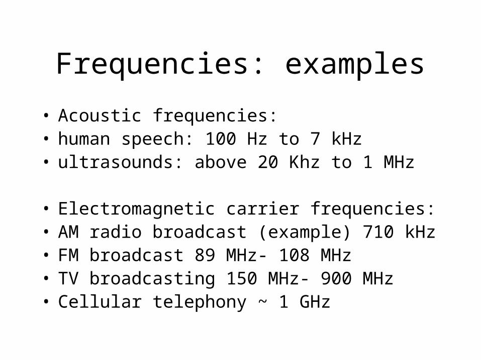
Frequencies: examples
• Acoustic frequencies:• human speech: 100 Hz to 7 kHz• ultrasounds: above 20 Khz to 1 MHz
• Electromagnetic carrier frequencies:• AM radio broadcast (example) 710 kHz• FM broadcast 89 MHz- 108 MHz• TV broadcasting 150 MHz- 900 MHz• Cellular telephony ~ 1 GHz
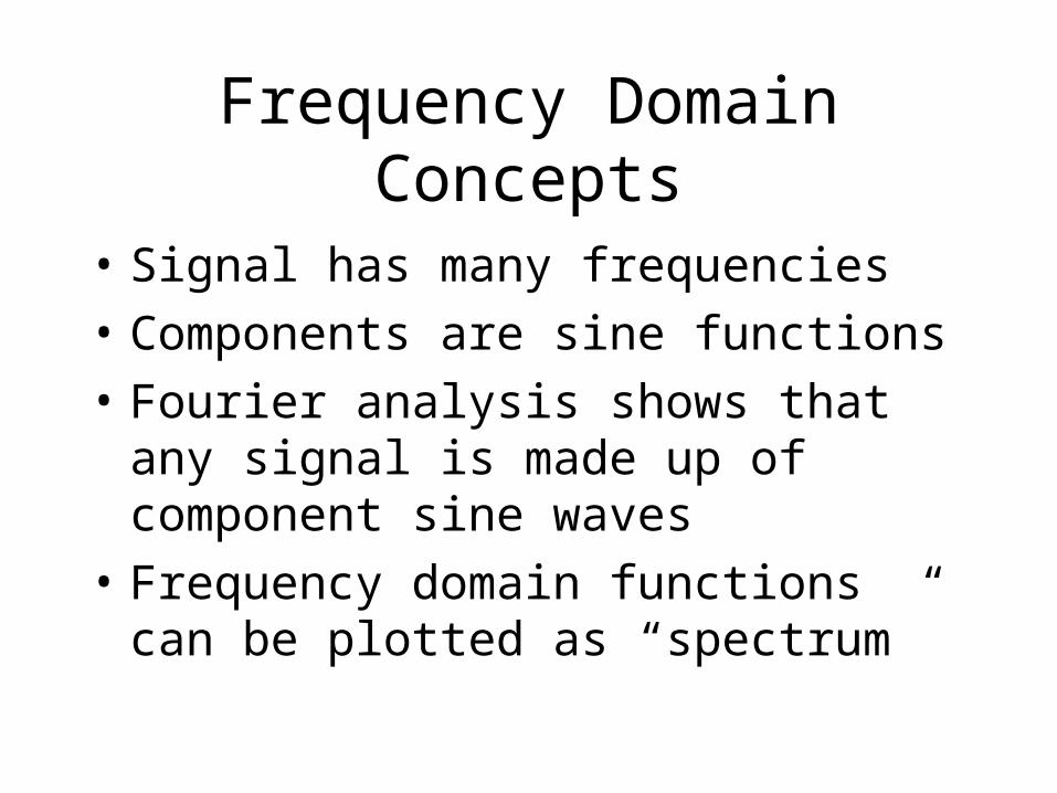
Frequency Domain Concepts
• Signal has many frequencies
• Components are sine functions
• Fourier analysis shows that any signal is made up of component sine waves
• Frequency domain functions can be plotted as “spectrum”
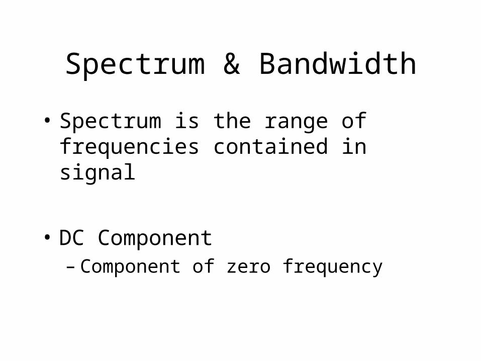
Spectrum & Bandwidth
• Spectrum is the range of frequencies contained in signal
• DC Component– Component of zero frequency
Data Rate and Bandwidth
• Any transmission system has a limited band of frequencies
• This limits the data rate that can be carried
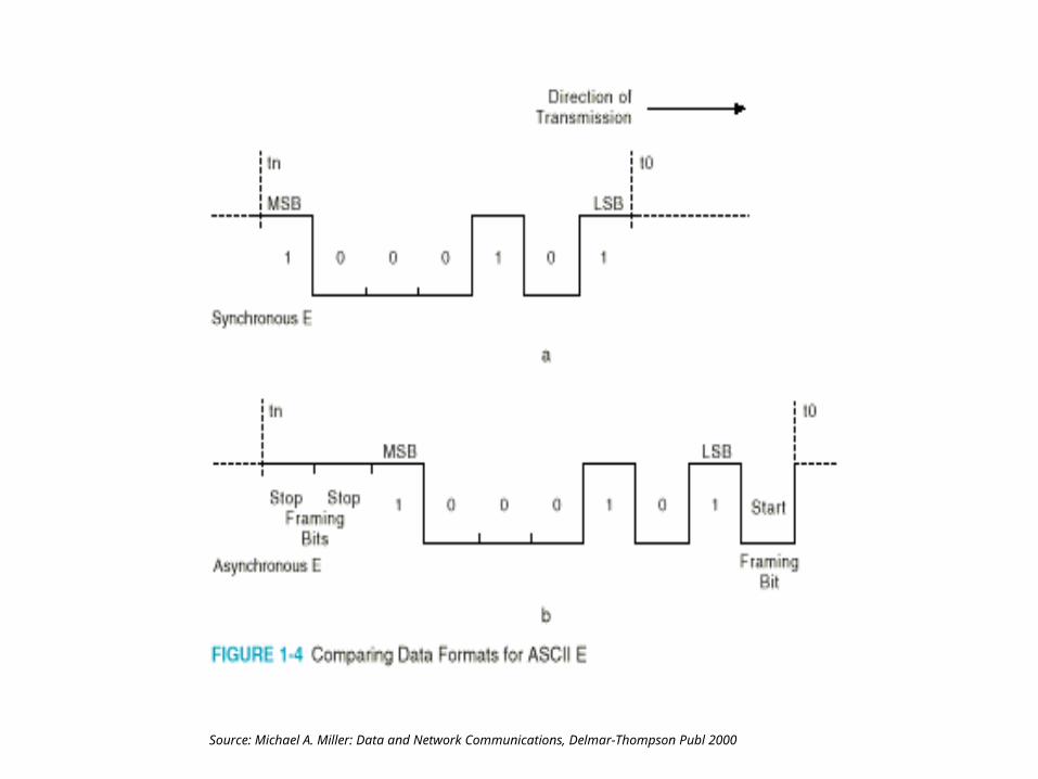
Source: Michael A. Miller: Data and Network Communications, Delmar-Thompson Publ 2000
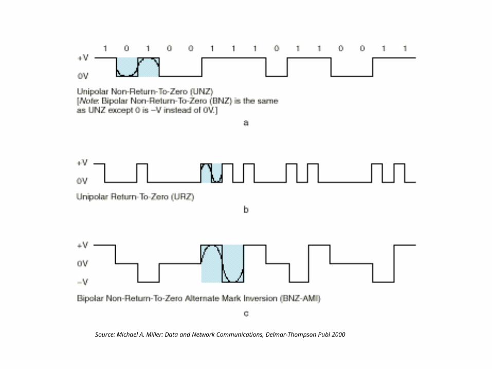
Source: Michael A. Miller: Data and Network Communications, Delmar-Thompson Publ 2000
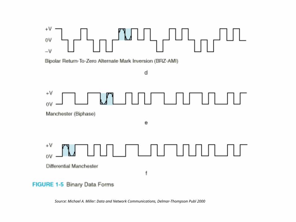
Source: Michael A. Miller: Data and Network Communications, Delmar-Thompson Publ 2000
Source: Michael A. Miller: Data and Network Communications, Delmar-Thompson Publ 2000