Embed Size (px)
Citation preview
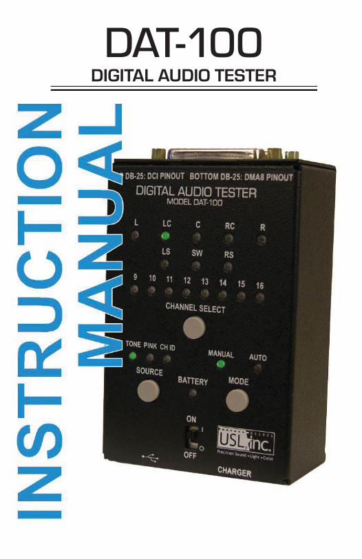
DAT-100DIGITAL AUDIO TESTER
- 2 -
- 3 -
Introductrion.....................................................................................................4
Batteries...........................................................................................................4
AES/EBU Outputs.............................................................................................5.Switches, Indicators & Connectors...................................................................6
DAT-100 Operation............................................................................................7
Mode Selection..................................................................................................7
Output Channel Selection..................................................................................6
Source..............................................................................................................8
Battery Indicator.................................................................................................8
Charger............................................................................................................8
Firmware Update...............................................................................................9
Connector Guide..............................................................................................10
TABLE OF CONTENTS
- 4 -
The DAT-100 is a simple handheld AES/EBU digital audio generator designed to assist cinema technicians debugging digital audio problems. The DAT-100 has two 25 pin output connectors to drive equipment with the USL or DMA8 digital audio pinout. Substitution of the DAT-100 for an AES/EBU source allows the technician to determine if a problem is in the source, the destination, or the cable between the two. The DAT-100 can also be used for a quick check of downstream equipment such as crossovers, power amplifi ers, speakers, and the speaker wiring. If audio from the DAT-100 is heard in the auditorium, the equipment is working properly. The DAT-100 allows the user to select which of the 16 audio channels are being driven. It may also be used as a quick check that the appropriate speaker is being driven by each audio channel.
The USL pin out is an industry standard pin out that was a proposed SMPTE stan-dard that was never adopted. Note that the front panel of the DAT-100 shows this as a “DCI Pinout.”
Introduction
BatteriesThe DAT-100 is shipped with two alkaline AA batteries installed. As an option, it is available with NiMH rechargeable batteries and an external charger.
When using rechargeable batteries and the USL supplied charger, turn the DAT-100 power switch to the off position to charge the batteries. The batteries will not be recharged when the DAT-100 is on. The DAT-100 cannot be powered by the external charger.
Use only the USL supplied charger and only with recharge-able batteries. Use of other chargers or batteries may damage the charger, the batteries or the DAT-100.
- 5 -
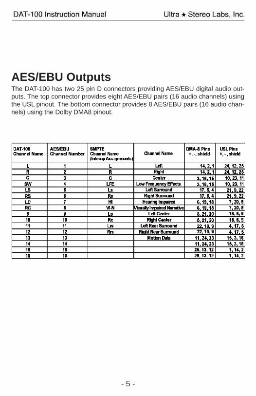
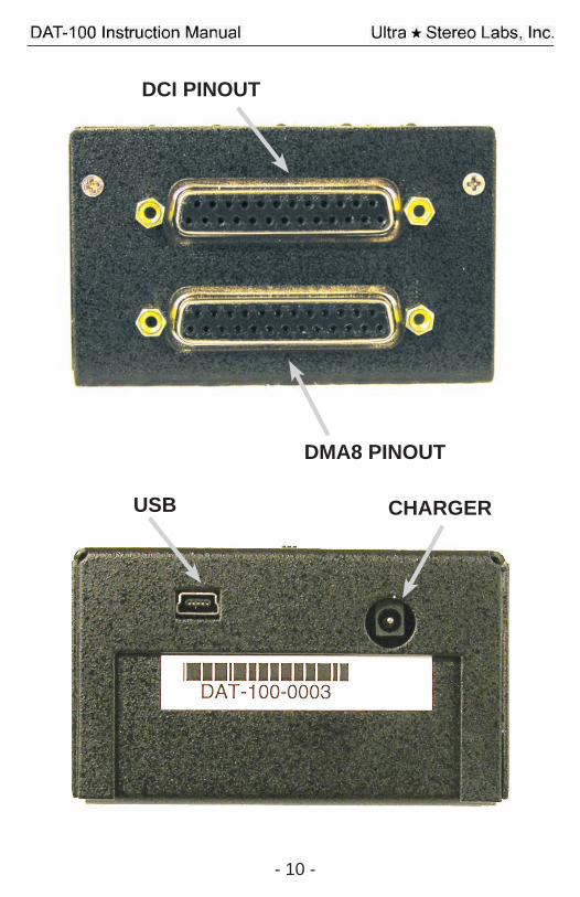
AES/EBU OutputsThe DAT-100 has two 25 pin D connectors providing AES/EBU digital audio out-puts. The top connector provides eight AES/EBU pairs (16 audio channels) using the USL pinout. The bottom connector provides 8 AES/EBU pairs (16 audio chan-nels) using the Dolby DMA8 pinout.
- 6 -
Switches, Indicators & Connectors
On/Off SwitchSlide the switch to the on position to turn on the unit. Slide the switch to the off position to turn the unit off and enable the optional external battery charger.
Power Indicator The power indicator lights when the unit is on. It fl ashes when the batteries are low and need replacement or recharging.
Source Button and Indicators The source indicators show which audio source (tone, pink noise, or channel ID) is currently driving the output. Press the source button to advance to the next source.
Mode Button and Indicators Press the mode button to change between manual and automatic channel chang-es. There are actually four modes: Manual 8 channel, Manual 16 channel, Auto-matic 8 channel, and Automatic 16 channel. When a mode is selected, the mode LED shows whether it is manual or automatic. The channel LED shows whether 8 or 16 channels will be used. Channel Select When in manual mode, the channel select advances the audio to the next output channel. The LEDs indicate the channel currently being driven. Audio Output Connectors As discussed above, the output connectors provide 8 or 16 channels of AES/EBU audio (one channel at a time) with either DMA8 or USL pinout.
Charger Connector Plug the USL supplied charger for the DAT-100 in to this connector. The internal NiMH batteries may only be recharged when the DAT-100 power switch is off. USB Connector Use this connector to connect to a host computer to update the fi rmware in the DAT-100.
- 7 -
DAT-100 OperationPlug an AES/EBU cable in to the appropriate output jack. Slide the power switch to ON. The BATTERY, TONE, MANUAL and “L” LEDs light. The BATTERY LED indicates the unit is on. If the BATTERY LED is fl ashing, the batteries need to be replaced or recharged. The TONE LED indicates the DAT-100 is producing a 1kHz tone at -20dBFS. The MANUAL LED indicates the unit is in Manual Mode. “L” LED indicates that the Left output is being driven in 8 channel mode.
Mode SelectThe DAT-100 can send audio to one of 16 channels. The channel can be selected Manually or advance Automatically. In addition, the DAT-100 can scan through the fi rst 8 channels or all 16 channels. Pressing and releasing the MODE button selects one of these four modes. In the MANUAL modes, the user advances the output to the next channel by pressing the Channel Select button. In the AUTO modes, the DAT-100 sequences through the 8 or 16 channels automatically.
Pressing and releasing the MODE button sequences through the followingmodes:
1. Manual, 8 channels (L LED lit) 2. Manual, 16 channels, (9 LED lit) 3. Automatic, 8 channels (L LED initially lit, then automatic advance
starts) 4. Automatic, 16 channels (9 LED initially lit, then automatic advance
starts
Note that the DAT-100 enters the Manual 8 channel mode each time it is pow-ered up.
Channel SelectPressing and releasing the CHANNEL SELECT button changes the output chan-nel being driven to the next channel in the 8 or 16 channel sequence (as set using the MODE button). In MANUAL modes, the channel does not advance until the CHANNEL SELECT button is pressed. In the AUTO modes, the output channel advances automatically, but the sequence can be sped up by pressing the CHAN-NEL SELECT button between automatic advances.
- 8 -
SourcePressing the source button advances the source selection to the next source. The DAT-100 can output a 1kHz tone at -20dBFS, pink noise, and a spoken channel identifi er. The source LEDs indicate which type of sound is currently being output. The spoken channel identifi er speaks the channel name (ie, L, LC, C, RC, etc.) or number (9, 10, 11, etc.) in English. The SW channel produces a 100Hz tone at -20dBFS in the tone and channel iden-tifi er source modes.
Battery IndicatorThe battery indicator glows steadily when the DAT-100 is on. If the indicator fl ash-es, the batteries are low and need to be replaced or recharged.
ChargerAs an option, the DAT-100 is available with rechargeable NiMH batteries and an external charger. To recharge the batteries, turn off the DAT-100, plug the charger in to the DAT-100, and the charger into an AC outlet. The charger has an LED that is red when the battery is charging and green when the battery has completed charging. The LED is also green when the charger is not connected to the DAT-100. Users may want to connect the DAT-100 to its charger each night to ensure the batteries are fully charged for the next day’s use.
Use only the USL supplied charger and only with rechargeable batteries. Use of other chargers or bat-teries may damage the charger, the batteries or the DAT-100.
- 9 -
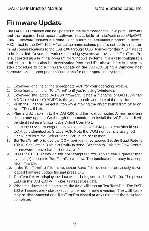
1. Download and install the appropriate VCP for your operating system. 2. Download and install TeraTermPro (if you’re using Windows). 3. Download the latest DAT-100 fi rmware. It has a fi lename of DAT100-YYM-
MDD.hex where YYMMDD is the year, month, and date of the revision. 4. Push the Channel Select button while moving the on/off switch from off to on.
No LEDs will light. 5. Plug a USB cable in to the DAT-100 and the host computer. A new hardware
dialog may appear. Go through the procedure to install the VCP driver. It will be identifi ed as a Silicon Labs Virtual Com Port.
6. Open the Device Manager to view the available COM ports. You should see a COM port identifi ed as SiLabs VCP. Note the COM number it is assigned.
7. Open TeraTermPro. Select Serial Port in the setup menu. 8. Set TeraTermPro to use the COM port identifi ed above. Set the Baud Rate to
19200. Set Data to 8 bit. Set Parity to none. Set Stop to 1 bit. Set Flow Control to hardware. Leave transmit delays at 0.
9. Press the ENTER key on the host computer. You should see a greater than symbol (>) appear in TeraTermPro window. The bootloader is ready to accept new fi rmware.
10. In the TeraTermPro File menu, select Send File. Select the previously down-loaded fi rmware update fi le and press OK.
11. TeraTermPro will display the data as it is being sent to the DAT-100. The power LED on the DAT-100 will fl icker as it receives data.
12. When the download is complete, the data will stop on TeraTermPro. The DAT-100 will immediately start executing the new fi rmware version. The USB cable may be disconnected and TeraTermPro closed at any time after the download completes.
Firmware UpdateThe DAT-100 fi rmware can be updated in the fi eld through the USB port. Firmware and the required host update software is available at http://uslinc.com/ftp/DAT-100/ . Firmware updates are done using a terminal emulation program to send a ASCII text to the DAT-100. A “virtual communications port” is set up to direct ter-minal communications to the DAT-100 through USB. A driver for this “VCP” needs to be installed. Drivers for various operating systems are available. TeraTerm Pro is suggested as a terminal program for Windows systems. It is easily confi gurable and reliable. It can also be downloaded from the URL above. Here is a step by step procedure to do a fi rmware update on the DAT-100 using a Windows host computer. Make appropriate substitutions for other operating systems.
- 10 -
USB CHARGER
DCI PINOUT
DMA8 PINOUT
WHEELIE-BIN SYMBOL
The Wheelie-Bin symbol is attached to this product in compliance with the EU Di-rective 2002/96/EC on Waste Electrical and Electronic Equipment (WEEE).Its purpose is to deter the improper disposal of this product and to promote reuse and recycling.
PROPER DISPOSAL
In conformance with the Directive, at end of life this product should be either:1) sent to an appropriate recycling facility for disassembly and recycling; or2) returned to the supplier.
Under no circumstances should this product be deposited in a landfi ll for disposal.
HAZARDS OF NON-COMPLIANCE
Electrical and electronic products may contain chemicals which can leach into the groundwater and cause health concerns through contaminated drinking water.Failure to dispose of this product in compliance with the WEEE Directive may result in penalties as determined by local ordinance.
181 Bonetti DriveSan Luis Obispo, CA 93401
ph: 805-549-0161fax: 805-549-0163
e-mail:[email protected]
Revision History120901 – Original Release130610 – Revise to show 16 channel DMA8 pin outs. Other edito-rial revisions.


![[DAT-903-C] iDirect Mediator - Remote Controlled Lighting · iDirect Mediator Version: 16.08 .16 PAGE 1 OF 1 PRODUCT SUMMARY DAT-903-C ORDER NO. 12314 100-240V 50/60Hz DESCRIPTION](https://img.pdfslide.us/doc/110x75/5e3738601b064e5e270b6a25/dat-903-c-idirect-mediator-remote-controlled-lighting-idirect-mediator-version.jpg)