Embed Size (px)
Citation preview

Using IOtech Data Acquisition Products with
DASYLab®
Using IOtech Data Acquisition
Products with DASYLab® 472-0902 rev 12
IOtech
25971 Cannon Road Cleveland, OH 44146-1833
(440) 439-4091 Fax: (440) 439-4093
[email protected] [email protected]
www.iotech.com *372193B-01* 372193B-01

DASYLab Driver Support
ACTIVE PRODUCTS Driver
Standard Enhanced
DASYLab 10 -
DaqBoard/1000 -
DaqBoard/2000 Series
DaqBoard/3000 Series -
DaqBook/2001/2005/2020
DaqBook/3000USB -
DaqLab/2001/2005 -
DaqScan/2001/2005 -
DaqTemp/14A -
DBK Options Support for Daq Products*
G-Sync Clock Synchronization Across Devices -
Multiple Device Support (hardware must be capable) -
Pers-Daq/3000/3001/3005 & PDQ 30 -
Scheduled Maintenance Releases -
600 Series Dynamic Signal Analyzers -
StrainBook/616 -
Support for Current & New Hardware Types -
TempBook/66 -
WaveBook/516E
WBK Option Modules for WaveBooks*
Windows Vista Support -
EOL PRODUCTS No longer available for sale. Driver
Standard Enhanced
DaqBoard/100A/112A/200A/216A ISA Boards -
DaqBoard/500 Series -
DaqBook/100/112/120/200/260/216 -
DaqScan/2002/2004 -
DaqTemp7/7A/14 -
WaveBook/512/512A/516/516A
* Certain DBK and WBK options have moved to EOL status. If needed, refer to DBK and/or WBK documentation for details.

© by IOtech 989791
About this Document
This document serves as a supplement to data acquisition device user’s manuals and to DASYLab documentation which is
included on the DASYLab installation CD. It is intended to help you with your initial setup of IOtech data acquisition
hardware in DASYLab.
The document steps through software installation configuration issues and provides screen shots so you can more
easily setup and use your equipment.
Since the document covers several different types of hardware look over the table of contents and refer only to the
section(s) that apply to your applications.
Contents
1 - Configuring DASYLab for Daq, WaveBook, Personal Daq/3000 Series Devices
– Enhanced Driver …… 1-1*
2 - Configuring DASYLab for Personal Daq/54, /55, and /56 …… 2-1
3- Configuring DASYLab for PointScan …… 3-1
4 - Configuring DASYLab for IOtech 640 & IOtech 650 Series – Enhanced Driver …… 4-1
Appendices
Appendix A - Configuring DASYLab for WaveBook - Standard Driver**…… A-1
Appendix B - Configuring DASYLab for Daq Devices - Standard Driver**…… B-1
Appendix C– Cal Notes for DBK19, DBK52, and TempBook/66 …… C-1
* Chapter 1 of this document provides: (1) an introduction to the enhanced driver, (2) driver installation instructions, and
(3) explains how to access the Help file. The Help file provides detailed configuration instructions for Daq,WaveBook,
Personal Daq/3000 Series, and IOtech 640 and 650 Series devices; and should be referred to after the enhanced driver
is installed.
** The Standard Driver does not support Windows Vista.
** The Standard Driver does not support DASYLab 10 (or higher).
Reference Note:
The DASYLab installation CD includes a “Getting Started with DASYLab” document in PDF format.
We highly recommend that you review that document, especially if you are new to DASYLab or have
been away from the application for an extended time.

ii 989791 DASYLab

DASYLab – Enhanced Driver 977391 Daq, WaveBook, & Personal Daq/3000 Series Devices 1-1
Configuring DASYLab for
Daq, WaveBook, and Personal Daq/3000 Series Devices 1
Enhanced DASYLab Driver
The IOtech enhanced driver uses the standard DASYLab A/D driver interface, which traditionally has supported a
single hardware device, with optional channel expansion cards. The IOtech standard DASYLab driver is an
example of a traditional single device support driver.
The IOtech enhanced DASYLab driver supports conventional single device applications within DASYLab as well.
Additionally, the enhanced driver supports acquiring data from multiple clock synchronized devices through the
standard DASYLab Analog Input module. The enhanced driver accomplishes this by creating a single large virtual
device inside DASYLab. Since from the DASYLab software perspective all input channels are located on a single
virtual device, data from all devices must be returned to DASYLab within a single data stream. The IOtech
Enhanced DASYLab driver and it's supporting DaqCOM driver layer handles the merging of data from multiple
devices into one data stream for DASYLab.
This single virtual device architecture forces from the DASYLab software perspective all input channels to acquire
data at the same sample rate. At the hardware level, devices may be designated as slave devices and acquire data at
even clock divisions of the master clock rate. The IOtech drivers handle padding scans of slow devices in the data
buffer to create a uniform input data stream.
Key Features of the IOtech Enhanced DASYLab Driver
Driver supports using standard DASYLab AI module, DASYLab version’s 6 , 7, 8, 9, 10. The Analog
Input Multi-Speed module introduced in DASYLab version 7 is not supported.
Supports multiple hardware devices synchronized to a common input scan clock. The IOtech driver layer
DaqCOM provides master / slave mode to support the clock synchronization.
Single data stream, configured through the standard DASYLab Experiment Setup dialog. All hardware
devices and expansion modules will acquire data in a single scan list and input buffer.
All devices MUST share same sample rate and block size from DASYLab’s view. Slow devices may run at
a even divisions of the master clock.
DASYLab hardware configuration may be imported/exported from IOtech DaqCOM and DaqExplorer
through XML files.
Supported Hardware
The IOtech Enhanced Driver for DASYLab supports a large number of Daq devices, WaveBooks, WBKs and DBKs.
IOtech 640 and 650 series devices are supported; but users of these products need to refer to chapter 4.
The Help file includes a list of supported devices. The list is updated as new products are released.
Reference Note:
Devices not supported by the Enhanced driver include:
o DaqBoard/100A, 112A, 200A, 216A
o TempBook/66
o DaqTemp/7, 7A, 14, 14A
Users of these devices should refer to Appendix A.
Users of IOtech 640 and 650 series devices, refer to chapter 4.

1-2 Daq, WaveBook, & Personal Daq/3000 Series Devices 977391 DASYLab –Enhanced Driver
Driver Specifications
Hardware Devices 32 Maximum (driver limitation)
Expansion Modules Limited only by hardware design ( typically 8 per device)
Analog Input Channels 512 Maximum (Sum of all devices & expansions)
Analog Output Channels 32 Maximum (Sum of all devices & expansions)
Digital I/O Ports 32 Maximum (Sum of all devices & expansions)
Counter Inputs 32 Maximum (Sum of all devices & expansions)
Frequency Output Channels 32 Maximum (Sum of all devices & expansions)
Maximum Aggregate Scan Rate Limited by CPU, PC Memory, Network Bandwidth, etc.
Upgrading from Previous Versions
The IOtech Enhanced Driver for DASYLab is a completely new design, not an upgrade to IOtech's Standard Driver.
If you have existing DASYLab worksheets using the Standard single device driver, it may be possible to switch to
the new Enhanced driver. However, the features and functionality of the two drivers in some configurations may not
match exactly.
Unless you need to add additional or new devices not supported in the Standard Driver, upgrading is not
recommended.
At this time, there is no automated method to read the hardware configuration from the standard support into the new
XML based configuration of the Enhanced Driver. To open a DASYLab worksheet [which was designed for the
Standard Driver] perform the following steps:
1. Make a backup of your worksheet .DSB file.
2. Open DASYLab worksheet with the Standard Driver active and closely examine the hardware
configuration tree. Make notes or screen shots as necessary.
3. Set the IOtech Enhanced Driver active in DASYLab.
4. Restart DASYLab as needed. When DASYLab reloads check the Help | About dialog and verify the
Enhanced Driver is loaded.
5. Open the hardware configuration dialog. Add devices to "New DASYLab Worksheet" tree view to
match the configuration used by the Standard Driver. Click OK to close hardware configuration dialog
when done.
6. Open the worksheet.
7. If you've successfully duplicated the configuration, no errors should occur.
8. Save the worksheet with the Enhanced Driver active. The Enhanced Driver will create an XML file
with the same base name as the worksheet to store your configuration.

DASYLab – Enhanced Driver 977391 Daq, WaveBook, & Personal Daq/3000 Series Devices 1-3
Software Installation
To use the Enhanced IOtech Driver for DASYLab, several layers of application and driver software are required as
outlined in the figure below.
The Enhanced DASYLab driver installation program installs all required software components onto the target
computer, except for the DASYLab application itself. However, there are still several steps to complete before
DASYLab and the hardware is ready to use on the computer, as outlined below.
Install DASYLab Application
1. Launch DASYLab installation from the DASYLab CD. Note that the CD should auto-start.
If the CD does not auto-start, run start.exe from the CD.
2. From the DASYLab splash screen, select “Install DASYLab.”
3. When prompted for your name, company and serial number, enter the requested data. Obtain the serial
number from the CD jacket. Keep the number in a safe place for future installations and upgrades.
4. When prompted for the installation directory and program folder, use the default selection, or choose another.
We recommend that the default directory and location be used.
5. When prompted for Setup Type, choose from the available options.
We recommend that you select Typical.

1-4 Daq, WaveBook, & Personal Daq/3000 Series Devices 977391 DASYLab –Enhanced Driver
6. Install the DEMO driver, and/or any of the other listed drivers as applicable.
After DASYLab has been installed you will install the IOtech Drivers from your IOtech Data
Acquisition CD, as described in the upcoming section.
7. Upon completing the DASYLab installation, exit from and remove the DASYLab CD.
Note: After software installation is complete you may be required to restart Windows.
After restart, continue with the following section, Installing DASYLab Drivers
for IOtech Devices.
Installing DASYLab Drivers for IOtech Devices
Note: The installation will automatically perform version verification to ensure that only newer
support is installed.
1. Place the IOtech Data Acquisition CD into your computer’s CD drive. The CD should auto-start; if
not, run the CD start.exe from the Windows Desktop.
2. After the intro screen appears, click <Enter Setup>.
3. After accepting the licensing agreement, select the hardware models that you will be using.
4. Select DASYLab Support.
5. Click the Start Install button. Follow the installation wizard configuration screens. Continue to
click <Next> [accepting the default values] until the DASYLab Hardware Driver Selection dialog
appears (following figure).

DASYLab – Enhanced Driver 977391 Daq, WaveBook, & Personal Daq/3000 Series Devices 1-5
6. Select: Enhanced Driver [Daq1000/2000/3000 Series, WaveBooks, 600 Series] See preceding figure.
7. Follow the installation wizard configuration screens until setup is complete.
Tip: Use DaqView, WaveView, or DaqCOM Explorer to verify connections and
configurations. These applications can be very beneficial, especially in applications
making use of DBK, WBK, or PDQ expansion or signal conditioning devices.
Note:
You can download the latest hardware and DASYLab drivers from our web site at
www.iotech.com.
Optional - Install WaveView, WaveCal, or DaqCal
Some WBK and DBK signal conditioning modules require calibration using one an external calibration program. Check
the hardware manual for calibration options available and install utilities as necessary.

1-6 Daq, WaveBook, & Personal Daq/3000 Series Devices 977391 DASYLab –Enhanced Driver
Using the Daq Configuration Control Panel Applet (for non-USB Devices) Main unit data acquisition devices such as the WaveBook, DaqBook, and DaqBoard non-USB devices must be installed
into the operating system by using the Daq* Configuration control panel applet.
1. The Control Panel is accessed through the Windows Start Menu.
Windows Vista Users: IOtech Data Acquisition CDs (versions 8.0 and higher) include a daqxcpl.exe
file which you must use if you need Windows Vista compatibility. After installing software from the
IOtech CD [or from our website (www.iotech.com)]; you can access the daqxcpl.exe file by navigating
from the Windows Desktop as follows:
Start menu Programs DASYLab Support Drivers DaqX Configuration Utility
2. Add and configure your data acquisition device in the control Daq Configuration Control Panel Applet. Refer to the
data acquisition user’s manual for instructions on using the applet and configuring device names.
The "Device Name" assigned to the data acquisition hardware in the Daq Configuration utility will
be imported and used within DASYLab for hardware identification.
3. Verify your hardware installation using the Resource
Test in the Daq Configuration Control Panel Applet.
After completing the Daq Configuration test use
WaveView, DaqView, or DaqCOM Explorer to verify
connections and configurations.
Using WaveView in this manner can be very
beneficial, especially in applications making use of
WBK signal conditioning expansion modules.

DASYLab – Enhanced Driver 977391 Daq, WaveBook, & Personal Daq/3000 Series Devices 1-7
Using the Control Panel Device Manager (for USB Plug-and-Play Devices) The PC will automatically detect plug-and-play data acquisition devices including those belonging to the series:
Personal Daq/3000, DaqBoard/3000USB, and DaqBook/3000USB. However; if you need to find the name of
your device, for example, if you are writing a custom program for multiple devices, navigate from the Windows
Desktop to the Device Manager. The navigation path is:
Start Settings Control Panel System Hardware(Tab) Device Manager DaqX PnP Devices
You will see the device listed under DaqX PnP Devices (see first figure, below). You can change the name of the
device by doing a right-click on the device name to open its properties dialog box, then clicking on the Properties
tab (see second figure). You can then change the “FriendlyName” of the device.
Locating DaqXPnP Devices Properties Dialog Box
Select the IOtech Driver in DASYLab
1. Start DASYLab and go to Measurement / Driver Selection
(see figure at right).
2. When the driver selection menu is presented, select IOtech
Enhanced DASYLab Driver from the list. You may be
prompted to restart DASYLab for the changes to take effect. If so,
exit and restart DASYLab before continuing.
3. Click HelpAbout DASYLab. The “Information about
DASYLab” screen will appear.
The screen’s “Version” tab states the versions of:
DASYLab, the active hardware DLL Driver, and the
low-level hardware Virtual Driver.
4. Verify that the DLL name is iotdcDASY.
5. Verify that the Virtual Driver name is DaqCOM.
The Enhanced DASYLab driver uses DaqCOM to communicate
with, control, and acquire data from the hardware.
6. Use the “Additional Options” tab to confirm that the options you
purchased have been properly installed.

1-8 Daq, WaveBook, & Personal Daq/3000 Series Devices 977391 DASYLab –Enhanced Driver
7. If you did not receive the version listed on your purchase order, contact IOtech’s Technical Support
Department at [email protected].
8. Click <OK> to close the “Information about DASYLab” window.
This completes the software installation process. At this point you can access DASYLab Help via the Help pull-down
menu; or access device-specific help as discussed below.
To access IOtech Device-specific help:
1. Open the Measurement pull-down menu in DASYLab (see preceding figure).
Note: In earlier versions of DASYLab the pull-down menu is labeled Experiment and the sub-menu item for
Measurement Setup is labeled Experiment Setup.
2. Select Hardware Setup.
3. Select Driver.

DASYLab – Standard Driver 896992 Configuring DASYLab for Personal Daq/54, 55, 56 2-1
Configuring DASYLab for Personal Daq/54, /55, /56 2
Note: This chapter does not apply to Personal Daq/3000 Series Devices.
Install DASYLab …… 2-2
Install Low-Level Hardware Driver …… 2-3
Configure Personal Daq …… 2-4
Software Support Structure
Simultaneous use of a Personal Daq/54, /55, or /56 and a WaveBook, DaqBook, or DaqBoard is not
recommended. During the Personal Daq’s calibration cycle, other data acquisition products will cease
operation, causing gaps in the collected data and potential buffer overruns.
Note: DASYLab has a “replace” feature which allows users to substitute worksheet icons. The replace feature does
not support 50 series Personal Daq hardware icons.

2-2 Configuring DASYLab for Personal Daq/54, 55, 56 896992 DASYLab - Standard Driver
Install DASYLab
1. Launch DASYLab installation from the DASYLab CD. Note that the CD should auto-start.
If the CD does not auto-start, run the CD start.exe from the Windows Desktop.
2. Select “Install DASYLab.”
3. When prompted for your name, company and serial number, enter the requested data.
Obtain the serial number from the CD jacket. Keep the number in a safe place for future installations
and upgrades.
4. When prompted for the installation directory and program folder, use the default selection,
or choose another. We recommend that the default directory and location be used.
5. When prompted for Setup Type, choose from the available options.
We recommend that you select Typical.
Note: You can select other drivers [for any other supported hardware you have] at this time.
Make sure a check mark appears next to your selection(s). Choices that are merely
highlighted and not checked will not be installed.
Note: If you allowed the IEEE488 (GPIB) drivers to be installed, you will be able to select the vendor.
Note: After software installation is complete, you may be required to restart Windows.
After restart, continue with the following section, Hardware Driver installation.
6. Install the DEMO driver, and/or any of the other listed drivers as applicable. Note that IOtech Drivers
will be installed from your IOtech installation CD, after DASYLab has been installed, as described in
the upcoming section.
7. Upon completing the DASYLab installation, exit from and remove the DASYLab CD.
Note: After software installation is complete you may be required to restart Windows.
After restart, continue with the following section, Installing DASYLab Drivers
for IOtech Devices.

DASYLab – Standard Driver 896992 Configuring DASYLab for Personal Daq/54, 55, 56 2-3
Install Low-Level Hardware Driver
If the low-level hardware drivers for your device are not installed, or if you have received a new IOtech
Personal Daq/54, /55, /56 Data Acquisition CD ( p/n 1022-0612), follow these steps.
Both the low-level drivers, installed from the Data Acquisition CD, and the DASYLab
drivers, installed from the DASYLab CD, are required for DASYLab operation.
Note: The installation will automatically perform version verification to ensure that only newer support is
installed.
1. Place the data acquisition CD into the CD-ROM drive. Wait for the PC to auto-run the CD. This
may take a few moments, depending on your PC. If the CD does not auto-run, use the Desktop’s
Start/Run/Browse feature to select and run Setup.exe.
2. After the intro screen appears, click <Enter Setup>.
3. After accepting the licensing agreement, select Personal DaqView.
4. Select DASYLab Support.
5. Click the <Install> button; and follow the screen prompts until the DASYLab Hardware Driver
Selection dialog appears (following figure).
6. Select Personal Daq 54/55/56.
7. Follow the installation wizard configuration screens until the setup is complete.
Use Personal DaqView to verify connections and configurations. This use of Personal
DaqView can be very beneficial, especially in applications making use of expansion modules.
Note: You can download the latest hardware and DASYLab drives from our web site at www.iotech.com.
2-4 Configuring DASYLab for Personal Daq/54, 55, 56 896992 DASYLab - Standard Driver
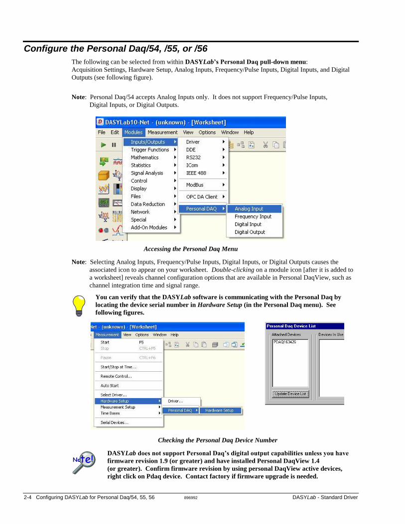
Configure the Personal Daq/54, /55, or /56
The following can be selected from within DASYLab’s Personal Daq pull-down menu:
Acquisition Settings, Hardware Setup, Analog Inputs, Frequency/Pulse Inputs, Digital Inputs, and Digital
Outputs (see following figure).
Note: Personal Daq/54 accepts Analog Inputs only. It does not support Frequency/Pulse Inputs,
Digital Inputs, or Digital Outputs.
Accessing the Personal Daq Menu
Note: Selecting Analog Inputs, Frequency/Pulse Inputs, Digital Inputs, or Digital Outputs causes the
associated icon to appear on your worksheet. Double-clicking on a module icon [after it is added to
a worksheet] reveals channel configuration options that are available in Personal DaqView, such as
channel integration time and signal range.
You can verify that the DASYLab software is communicating with the Personal Daq by
locating the device serial number in Hardware Setup (in the Personal Daq menu). See
following figures.
Checking the Personal Daq Device Number
DASYLab does not support Personal Daq’s digital output capabilities unless you have
firmware revision 1.9 (or greater) and have installed Personal DaqView 1.4
(or greater). Confirm firmware revision by using personal DaqView active devices,
right click on Pdaq device. Contact factory if firmware upgrade is needed.

DASYLab – Standard Driver 896992 Configuring DASYLab for Personal Daq/54, 55, 56 2-5
DASYLab’s Personal Daq menu includes an Acquisition Settings dialog box for setting the Acquisition
Rate, Block Size, and Accuracy (Continuous Calibration and/or Overrange Protection). The dialog box also
includes a system Status panel.
Accessing Personal Daq Acquisition Settings Personal Daq Acquisition Settings
When using Personal Daq you should use the Personal Daq Acquisition Settings
window to set the Acquisition Rate and Block Size (see the preceding figure). You
should not use the Experiment Setup window to do this, as these two parameter values
are not generally coordinated between windows. An exception is that Block Sizes will
be coordinated if the checkbox for “Use Global Block Size” is checked.
A screen similar to that in the following figure appears after selecting Analog Inputs and double-clicking on
the module icon [after it is added to a worksheet]. Notice that the device serial number appears on this
screen.
Personal Daq Analog Input Settings
In the screen (see preceding figure) you must assign physical channels on the Personal Daq [and on PDQ1
and PDQ2, if present] to virtual channels in the A/D module. This is accomplished by highlighting each of
the virtual channels in the 0 to 15 channel bar and then defining channel parameters as follows:
Select Single-Ended or Differential
Select the Channel; this is the physical channel number. Guidelines and examples follow the
bulleted list.
Select the Range
Select the Sample Duration.

2-6 Configuring DASYLab for Personal Daq/54, 55, 56 896992 DASYLab - Standard Driver
Use the following guidelines when selecting a physical channel number.
Make sure that the physical channel that you are assigning exists in your hardware
configuration. For instance, it would be a mistake to assign channel 6 for a Personal
Daq/55, as that product has no channel 6. If a nonexistent channel is assigned DASYLab
will display an error message when you try running the worksheet.
During the assignment process, both differential and single-ended channels can be used.
You may skip physical channels during the assignment process. However, you must
assign physical channels to virtual ones in monotonic ascending order. If you fail to do
this the driver will rearrange them, resulting in virtual channels with different information
than that which is expected. Examples of good and bad assignments follow.
Examples of Good and Bad Channel Assignments
Good
Virtual Channels 0 1 2 3 4 5
Physical Channels 1 2L 3 4 11 12L
Bad
Virtual Channels 0 1 2 3 4 5
Physical Channels 1 2L 5H 13H 4L 5L
In this case the driver will rearrange the physical channels as follows:
Virtual Channels 0 1 2 3 4 5
Physical Channels 1 2L 4L 5L 5H 13H

DASYLab – Standard Driver 876994 Configuring DASYLab for PointScan 3-1
Configuring DASYLab for PointScan 3
Overview …… 3-1 IOtoolKit …… 3-2
Install the IOtoolKit …… 3-2 Reserve Addresses …… 3-2 Ethernet Configuration …… 3-2 Configure the System via the IOtoolKit …… 3-4
KEPServerEx …… 3-5 Install the KEPServerEx Software …… 3-5 Configure KEPServerEx …… 3-5
DASYLab …… 3-6 Install DASYLab …… 3-6 Connect DASYLab to the OPC Server …… 3-7
Software Support Structure
Overview This chapter covers the steps necessary for a successful installation of DASYLab for use in PointScan applications. The chapter sections are presented in chronological order, as indicated in the table of contents above.
In order to complete all steps successfully, you will need the following at, or above, the indicated version level.
• IOtoolKit Installation CD, version 1.2 (p/n 1075-0601)* • KEPServerEx, version 4.0 (included on the IOtoolKit CD)* • DASYLab Installation CD, version 6.0 (p/n 472-0606)* • Internet Explorer, version 5.0* • PointScan/104, PointScan/204, & PointScan/443 Power Supply
*The version numbers indicated are the lowest version levels required to ensure a successful installation of DASYLab for PointScan applications.

3-2 Configuring DASYLab for PointScan 876994 DASYLab – Standard Driver
IOtoolKit
Install the IOtoolKit 1. Insert the IOtoolKit CD (p/n 1075-0601) into the CD drive.
Note: The CD should auto-start. If the CD does not auto-start, run the CD start.exe from the Windows Desktop.
2. Browse to the contents of your CD drive.
3. Open the IO Tools Install folder.
4. Click on setup.exe.
5. Follow the prompts to complete the installation.
6. From the Windows Start menu select: Programs, and then IO Tools. The program will now load.
Reserve Addresses After assembling the PointScan hardware, work with your network administrator to reserve a bank of network addresses for:
• the host computer • the PointScan modules that will be connected to the Ethernet
You can use a “485 Pass-Through” connection to reduce the required number of addresses. The pass-through allows you to use a single address to connect up to eight PointScan modules to the Ethernet.
Ethernet Configuration The Ethernet port on your PC must be configured. Windows 98 and higher includes TCP/IP (the networking protocol) for Internet access. Your PC’s Ethernet port will be assigned a unique IP address [10.X.Y.Z] used to communicate with the Ethernet-based PointScan/104 module.

DASYLab – Standard Driver 876994 Configuring DASYLab for PointScan 3-3
Set-up for Windows¨ 9x Use the below instructions to modify existing TCP/IP settings.
1. Select Start ⇒ Settings ⇒ Control Panel ⇒ Network
If TCP/IP does not exist in the components window Press Add ⇒ Protocol ⇒ TCP/IP.
2. Double Click on TCP/IP in the components window and select the IP Address tab.
3. Press OK to close the network dialog and reboot your computer if instructed to do so.
Win 9x: Example of Setting TCP/IP values

3-4 Configuring DASYLab for PointScan 876994 DASYLab – Standard Driver
Setup for Windows¨ 2000 Use the below instructions to modify existing TCP/IP settings.
1. Select Start ⇒ Settings ⇒ Network and Dial-up connections
2. Double Click on Local Area Connection and click Properties.
If TCP/IP does not exist in the components window press Install ⇒ Protocol ⇒ TCP/IP.
3. Double Click on TCP/IP and fill in the Values and press OK
4. Press OK to close the network dialog and reboot your computer if instructed to do so.
Windows 2000: Example of Setting TCP/IP values
Configure the System via the IOtoolKit Use the IOtoolKit software to perform the system configuration. Instructions are included on the CD (see the following reference note). Configuration includes:
• setting up the IP address for PointScan modules that have a direct Ethernet connection
• setting up the pass through communication protocol to additional devices that are using a 485 pass-through
• naming stations and channel tags
• setting measurement parameters for channels, e.g., integration time and ranges.
• saving the configuration
• verifying system communications
Reference Note: Refer to Getting started with the IOtoolKit, located within the IOtoolKit Help document, for instructions related to the above topics.
For backup purposes, save the settings as a project file.

DASYLab – Standard Driver 876994 Configuring DASYLab for PointScan 3-5
KEPServerEx After completing your work with the IOtoolKit, you will need to install the KEPServerEx OPC Server Software and then configure KEPServerEx. OPC stands for OLE for Process Control, where OLE is the acronym for Object Linking and Embedding.
The IOtoolKit CD (p/n 1075-0601) includes a free, unlicensed version of the KEPServerEx software, related instructions, and prompts.
Note: The free unlicensed version of KEPServerEx [included on the IOtoolKit CD] supports up to three hours of operation before it is necessary to re-boot the system. A licensed version of KEPServerEx software, that provides continuous operation, can be purchased through IOtech. Contact information is provided on the cover page of this document.
Install the KEPServerEx Software 1. Insert the IOtoolKit CD (p/n 1075-0601) into the CD drive.
Note: The CD should auto-start. If the CD does not auto-start, run the CD start.exe from the Windows Desktop.
2. Browse to the contents of your CD drive.
3. Open the KEPServer folder.
4. Double click on disk1.
5. Click on setup.exe.
6. Follow the prompts to complete the installation.
7. From the Windows Start menu: select Programs, then KEPServerEX. The program will now load.
Configure KEPServerEx KEPServerEx configuration is discussed in help files that are included on the IOtoolKit CD (p/n 1057-0601). Reference notes to those documents are provided below.
DASYLab can only recognize the short data format; thus, KEPServerEx must be configured for short data format.
The scan rate must be specified for a fixed scan rate, not to transmit data only when a change occurs.
Reference Notes: Refer to the KEPServerEx Help document [located on the IOtoolKit CD] for information
regarding how to: • add station names and channel tag names • specify device IP addresses and channel Modbus addresses • prove the IO communication with all devices using the OPC <QuickClient>
button • save the configuration for backup purposes
Refer to the EtherTRAK Help document [located on the IOtech Toolkit CD] for a list of modbus addresses for each module’s channel type. Channel configurations [for specific channels] require that the modbus address and the data format be specified.
After completing the KEPServer configuration, use the OPC <QuickClient> button to test all PointScan modules and channel configurations.

3-6 Configuring DASYLab for PointScan 876994 DASYLab – Standard Driver
DASYLab
Install DASYLab
DASYLab software versions that precede 6.0 do not support PointScan products. If your DASYLab version precedes 6.0, please contact [email protected] for upgrade information.
For DASYLab to properly install, the host computer must be using Internet Explorer version 5.0 or higher.
Install DASYLab as follows:
1. Launch the DASYLab installation from the DASYLab CD.
Note: The CD should auto-start. If the CD does not auto-start, run the CD start.exe from the Windows Desktop.
2. Select “Install DASYLab.”
3. When prompted for your name, company and serial number, enter the requested data. Obtain the serial number from the CD jacket.
Keep the serial number in a safe place. You may need to reference it for future installations and upgrades.
4. When prompted for the installation directory and program folder, you can use the default selection, or choose another. We recommend using the default.
5. When prompted for Setup Type, choose from the available options. We recommend that you select Typical.
6. Select the applicable hardware drivers when prompted. See the following note and figure.
There are no PointScan related drivers to select. The drivers that are selected in step 6 are for components that are in addition to PointScan.
Be sure to place a check mark next to each of your selections. Choices that are not checked will not be installed, even if they are highlighted.
Selecting Drivers in DASYLab Setup A screen displays the selected options. If needed, use the <Back> button and make the appropriate changes.

DASYLab – Standard Driver 876994 Configuring DASYLab for PointScan 3-7
In the case of IEEE488 (GPIB) drivers, be sure that the vendor identity is correct. Windows NT/2000 may require installation of DataSocket support after installation
of DASYLab. You will receive a message prompt, should installation of DataSocket support be required.
Connect DASYLab to the OPC Server
Before connecting DASYLab to the OPC Server, verify that the OPC server is receiving valid readings from the PointScan device.
Complete the following steps to connect DASYLab to the server.
1. From a DASYLab worksheet, access the DataSocket Import Setup screen by navigating as follows from the toolbar (see first figure):
⇒ Modules [pull-down menu] ⇒ Network
⇒ DataSocket Import (left-click to bring up a DataSocket Import Icon)
Double-click on the DataSocket Import Icon (not shown) to open the DataSocket Import Setup dialog box (see second figure).
Selecting DataSocket Import
DataSocket Import Setup
2. Click on the triangular add button [item 2 in the above figure] to add the desired number of channels. Each click of the button will sequentially place a socket image beneath a channel. In the preceding figure socket images can be seen for channels 0, 1, 2, and 3.

3-8 Configuring DASYLab for PointScan 876994 DASYLab – Standard Driver
Note: If your system has more than 16 channels, you will need to put an additional DataSocket Import module on your worksheet.
3. Configure a channel; steps 3(a) through (f).
DataSocket Import Setup
3(a) Select the channel that is to be configured. Note that a green socket indicates the channel for which selected options will be applied. In the previous figure, channel 0 is selected.
3(b) For the connection Type, select OPC.
3(c) Click on the <Select Item> button.
DASYLab will search the computer registries and list every OPC server program that resides on your computer.
3(d) Locate and expand the OPC Server Software identifier (see following figure). In the figure we selected KEPware.KEPServerEx for the Kepware OPC Server Software. In addition, we expanded Channel 1 to show PointScan104 and its associated tags (Temp1 and Temp2); as well as PointScan204 (not shown in its entirety) to show its associated channel tags (Temp3 and Temp4). You would need to scroll down to see Temp3 and Temp4.
Expanding the Server Item

DASYLab – Standard Driver 876994 Configuring DASYLab for PointScan 3-9
3(e) From the expanded list, select the channel tag that applies to the channel currently being configured. In our example tags will be assigned to channels as follows: PointScan104 / Temp1: Channel 0 PointScan104 / Temp2: Channel 1 PointScan204 / Temp3: Channel 2 PointScan204 / Temp4: Channel 3
3(f) For the channel that is being configured, select the desired “tag” by highlighting it; then click <OK>.
3(g) Click the <Options> button (following figure). The Data Socket Import Options box will open.
3(h) Enter the time value for the scan rate and Click <OK>. The resulting scan rate, i.e., data return per unit time, is what we want DASYLab to use for the PointScan device. The previous figure indicates that we want to have data returned every 0.1000 seconds, (10 samples/sec). Note that the time factor entered here will later be entered in the Experiment Setup window [step 9, page 3-10].
4. Repeat step 3 for each of the remaining channels. Continue with step 5 after all channels have been configured.
5. Click the <Save> button and save your setup under an appropriate filename and location.
6. Close the DataSocket Import Setup box.
7. From the Experiment pull-down menu, select Experiment Setup. An Experiment Setup box will appear (following figure).
Click the <Options> button to open the DataSocket Import Options box. Step 3(g).
Enter the time value for the Scan Rate. Step 3(h).

3-10 Configuring DASYLab for PointScan 876994 DASYLab – Standard Driver
Setting Block Size and Scan Rate in Experiment Setup
8. In the Experiment Setup window, in the Global Settings frame (see above figure), verify that Auto Select is unchecked and that the Block Size is set to 1.
9. In the Global Settings frame, under Sampling Rate/Ch, set the time value to the match the value that was specified in the DataSocket Import Options box [step 3(h), page 3-9]. Set the units to Sec. The resulting scan rate, i.e., data return per unit time, is for data to be returned once every 0.1000 seconds. This is equal to 10 samples/sec.
For each DASYLab worksheet module ⎯ in the Experiment Setup window, set the Block Size and the Sampling Rate to match that of the first module. This will ensure that the data from each worksheet module coincides with the data from the DataSocket Import module.
10. Close the Experiment Setup window.
11. From the Module pull-down menu, select Display, then select an appropriate display module. This will allow you to see the data after the play button is clicked.
This completes the procedure for configuring DASYLab for PointScan.
DataSocket Import Module attached to a Digital Meter Module

DASYLab – Enhanced Driver 977491 IOtech 640 & 650 Series Devices 4-1
Configuring DASYLab for
IOtech 640 and 650 Series Devices 4
Enhanced DASYLab Driver
The IOtech enhanced driver uses the standard DASYLab A/D driver interface, enabling it for use with a single
IOtech 640 series or 650 series device in a DASYLab worksheet.
There is no means to use multiple 640 or 650 devices, or to expand upon a single 640 or 650.
Key Features of the Driver as applicable to 640 & 650 Series Devices
Driver supports using standard DASYLab AI module, DASYLab version’s 9 and 10. The Analog Input Multi-Speed module introduced in DASYLab version 7 is not supported.
IOtech 640 and 650 series device properties are configured using the standard DasyLab Hardware setup dialog.
DASYLab hardware configuration may be imported/exported from IOtech DaqCOM and DaqExplorer through XML files.
Supports IOtech 640 series with 4 dynamic signal analog input channels and one waveform output channel. Analog input channels 1 through 4 are IEPE bias source compatible, programmable per channel (see product specs).
Supports IOtech 650 series with 5 dynamic signal analog input channels. Analog input channels 1 through 4 are IEPE bias source compatible, programmable per channel.
Supports full scan rate capability of 25.75 to 105,468 scans per second.
AC/DC coupling, TEDS detection, and high pass filtering properties [of the dynamic signal channels] are software selectable per channel.*
Read-only ICP Status and Voltage fields displayed per channel.*
8-bit digital IO port available as an 8-bit input port or an asynchronous 8-bit output port.
The Analog Output channel [640 units only] can be used asynchronously for DAC value updates, synchronously for streaming data from DASYLab worksheet. Data streamed to the analog output channel can be set for fixed, predefined, waveforms.
Supports continuous and fixed length acquisitions.
Supports immediate, manual, and channel value trigger events.
* Note: For 650 series devices, channel 5 is not IEPE capable (see product specs).

4-2 IOtech 640 & 650 Series Devices 977491 DASYLab –Enhanced Driver
Software Installation
To use the Enhanced IOtech Driver for DASYLab, several layers of application and driver software are required as
outlined in the figure below.
The Enhanced DASYLab driver installation program installs all required software components onto the target
computer, except for the DASYLab application itself. However, there are still several steps to complete before
DASYLab and the hardware is ready to use on the computer, as outlined below.
Install DASYLab Application
1. Launch DASYLab installation from the DASYLab CD. Note that the CD should auto-start.
If the CD does not auto-start, run start.exe from the CD.
2. From the DASYLab splash screen, select “Install DASYLab.”
3. When prompted for your name, company and serial number, enter the requested data. Obtain the serial
number from the CD jacket. Keep the number in a safe place for future installations and upgrades.
4. When prompted for the installation directory and program folder, use the default selection, or choose another.
We recommend that the default directory and location be used.
5. When prompted for Setup Type, choose from the available options.
We recommend that you select Typical.

DASYLab – Enhanced Driver 977491 IOtech 640 & 650 Series Devices 4-3
6. Install the DEMO driver, and/or any of the other listed drivers as applicable.
After DASYLab has been installed you will install the IOtech Drivers from your IOtech Data
Acquisition CD, as described in the upcoming section.
7. Upon completing the DASYLab installation, exit from and remove the DASYLab CD.
Note: After software installation is complete you may be required to restart Windows.
After restart, continue with the following section, Installing DASYLab Drivers
for IOtech Devices.
Installing DASYLab Drivers for 640 and 650 Series Devices
Note: The installation will automatically perform version verification to ensure that only newer
support is installed.
1. Place the IOtech DSA CD (rev 2.1 or higher) into the host computer’s CD drive. The CD should
auto-start; if not, run the CD start.exe from the Windows Desktop.
2. After the intro screen appears, click <Enter Setup>.
3. After accepting the licensing agreement, select the hardware models that you will be using.
4. Select DASYLab Support.
5. Click the Start Install button. Follow the installation wizard configuration screens. Continue to
click <Next> [accepting the default values] until the DASYLab Hardware Driver Selection dialog
appears (following figure).

4-4 IOtech 640 & 650 Series Devices 977491 DASYLab –Enhanced Driver
6. Select: Enhanced Driver [Daq1000/2000/3000 Series, WaveBooks, 600 Series
See preceding figure.
7. Follow the installation wizard configuration screens until setup is complete.
Using the Daq Configuration Control Panel Applet (for 640e and 650e)
IOtech 640e and 650e must be installed into the operating system by using the Daq* Configuration control panel applet.
1. The Control Panel is accessed through the Windows Start Menu.
Windows Vista Users: A file called daqxcpl.exe must be used if you want Windows Vista
compatibility. After installing software from the IOtech CD [or from our website (www.iotech.com)];
you can access the daqxcpl.exe file by navigating from the Windows Desktop as follows:
Start menu Programs DASYLab Support Drivers DaqX Configuration Utility
2. Add and configure your data acquisition device in the control Daq Configuration Control Panel Applet. Refer to the
data acquisition user’s manual for instructions on using the applet and configuring device names.

DASYLab – Enhanced Driver 977491 IOtech 640 & 650 Series Devices 4-5
The "Device Name" assigned to the data acquisition hardware in the Daq Configuration utility will
be imported and used within DASYLab for hardware identification.
3. Verify your hardware installation using the Resource
Test in the Daq Configuration Control Panel Applet.

4-6 IOtech 640 & 650 Series Devices 977491 DASYLab –Enhanced Driver
Using the Control Panel Device Manager (for 640u and 650u)
The host PC will automatically detect plug-and-play data acquisition devices such as the 640u and 650u. However;
if you need to find the name of your device, for example, if you are writing a custom program, navigate from the
Windows Desktop to the Device Manager. The navigation path is:
StartSettingsControl PanelSystemHardware(Tab) Device ManagerDaqX PnP Devices
You will see the device listed under DaqX PnP Devices (see first figure, below). You can change the name of the
device by doing a right-click on the device name to open its properties dialog box, then clicking on the Properties
tab (see second figure). You can then change the “FriendlyName” of the device.
Locating DaqX PnP, 650u Devices 650u Properties Dialog Box
Select the IOtech Driver in DASYLab
1. Start DASYLab and go to Measurement / Driver Selection
(see figure at right).
2. When the driver selection menu is presented, select the IOtech
Enhanced DASYLab driver from the list. You may be prompted
to restart DASYLab for the changes to take effect. If so, exit and
restart DASYLab before continuing.
3. Click HelpAbout DASYLab. The “Information about
DASYLab” screen will appear.
The screen’s “Version” tab states the versions of:
DASYLab, the active hardware DLL Driver, and the
low-level hardware Virtual Driver.
4. Verify that the DLL name is iotdcDASY.
5. Verify that the Virtual Driver name is DaqCOM.
The Enhanced DASYLab driver uses DaqCOM to communicate
with, control, and acquire data from the hardware.
6. Use the “Additional Options” tab to confirm that the options you
purchased have been properly installed.

DASYLab – Enhanced Driver 977491 IOtech 640 & 650 Series Devices 4-7
Note: If you did not receive the version listed on your purchase order, contact IOtech’s Technical Support
Department at [email protected].
7. Click <OK> to close the “Information about DASYLab” window.
This completes the software installation process. At this point you can access DASYLab Help via the Help pull-down
menu; or access device-specific help as discussed below.
To access IOtech Device-specific help:
1. Open the Measurement pull-down menu in DASYLab [preceding figure]. (See note)
2. Select Hardware Setup.
3. Select Driver.
Note: In earlier versions of DASYLab the Measurement pull-down menu is labeled Experiment and the
Hardware Setup sub-menu item is labeled Experiment Setup.

4-8 IOtech 640 & 650 Series Devices 977491 DASYLab –Enhanced Driver
Notes:

DasyLab - Standard Driver 989693 Configuring DASYLab for WaveBook A-1
Appendix A Configuring DASYLab for WaveBook Standard DASYLab Driver (DaqBoard/DaqBook/WaveBook/TempBook)
IOtech WaveBook users now have two choices of DASYLab drivers. These are:
Standard DASYLab Driver (DaqBoard/DaqBook/WaveBook/TempBook)
Enhanced DASYLab Driver (with multiple WaveBook and WBK40/41 support)
You should use the Enhanced DASYLab Driver if:
• You wish to run multiple WaveBook systems concurrently.
• You are using WBK40/41 modules in your system.
You should use the Standard DASYLab Driver if:
• You have already created DASYLab Worksheets for your system and you do not plan to use WBK40/41 modules or multiple WaveBooks in your system.
• You require optimal throughput performance while using a single WaveBook system.
If neither of the above scenarios applies, then either driver can be used for your WaveBook DASYLab application.
Note: You can download the latest hardware and DASYLab drives from our web site at www.iotech.com.
Reference Notes:
Users of the Enhanced DASYLab Driver refer to chapter 1.
Users of the Standard DASYLab Driver refer to this Appendix.
Install DASYLab …… A-2 Install Low-Level Hardware Driver …… A-3 Select the Driver …… A-4 Configure the Hardware …… A-5 Putting Modules on the Worksheet …… A-8 Working with the WaveBooks
and WBK Options …… A-8 WaveBook …… A-9 WBK14 …… A-8 WBK15 …… A-9 WBK16 …… A-11 WBK17 …… A-12 WBK18 …… A-13 WBK40 …… (refer to chapter 2) WBK41 …… (refer to chapter 2)
FIFO Settings (for WBK30 Option) …… A-15 General Experiment Setup …… A-17

A-2 Configuring DASYLab for WaveBooks 989693 DASYLab - Standard Driver
Software Support Structure
Install DASYLab 1. Launch DASYLab installation from the DASYLab CD. Note that the CD should auto-start.
If the CD does not auto-start, run start.exe from the CD.
2. Select “Install DASYLAb.”
3. When prompted for your name, company and serial number, enter the requested data. Obtain the serial number from the CD jacket. Keep the number in a safe place for future installations and upgrades.
4. When prompted for the installation directory and program folder, use the default selection, or choose another. We recommend that the default directory and location be used.
5. When prompted for Setup Type, choose from the available options. We recommend that you select Typical.
6. Install the DEMO driver, and/or any of the other listed drivers as applicable.
After DASYLab has been installed you will install the IOtech Drivers from your IOtech Data Acquisition CD, as described in the upcoming section.
Make sure a check mark appears next to your selection(s). Choices that are merely highlighted and not checked will not be installed.
7. A final screen displays the selected options about to be installed. Be sure the report matches your intended choices. Step back to modify settings if needed.
Note: After software installation is complete you may be required to restart Windows. After restart, continue with the following section, Install Low-Level Hardware Driver.

DasyLab - Standard Driver 989693 Configuring DASYLab for WaveBook A-3
Install Low-Level Hardware Driver If the hardware drivers for your device are not yet installed, or if you have received a new IOtech Data Acquisition CD, follow these steps.
Both the low-level drivers, installed from the Data Acquisition CD, and the DASYLab drivers, installed from the DASYLab CD, are required for DASYLab operation.
Note: The installation automatically performs version verification. Only newer support is installed.
1. Launch the Data Acquisition Software CD. Note that the CD should auto-start. If not, run start.exe from the CD.
2. Select the hardware models that you will be using.
3. Select DASYLab Support.
4. Click the Start Install button.
5. When the DASYLab Hardware Driver Selection dialog appears select Standard Driver [DaqBook/Board 100 & 2000 Series, DaqTemp, TempBook].
Use WaveView to verify connections and configurations. This use of WaveView can be very beneficial, especially in applications making use of DBK signal conditioning cards and expansion modules.
6. Verify your hardware installation using the Resource Test in the Daq Configuration Control Panel Applet. Refer to the data acquisition user’s manual for instructions on using the applet and configuring device names.
Note: You can download the latest hardware and DASYLab drives from our web site at www.iotech.com.
Selecting the Daq* Configuration Control Panel Applet
Reference Note: After completing the following driver-selection and hardware setup steps you will be ready to add icons to your worksheet. Refer to DASYLab’s On-line Help for detailed information.
A-4 Configuring DASYLab for WaveBooks 989693 DASYLab - Standard Driver
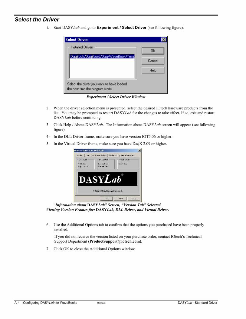
Select the Driver 1. Start DASYLab and go to Experiment / Select Driver (see following figure).
Experiment / Select Driver Window
2. When the driver selection menu is presented, select the desired IOtech hardware products from the
list. You may be prompted to restart DASYLab for the changes to take effect. If so, exit and restart DASYLab before continuing.
3. Click Help / About DASYLab. The Information about DASYLab screen will appear (see following figure).
4. In the DLL Driver frame, make sure you have version IOT5.06 or higher.
5. In the Virtual Driver frame, make sure you have DaqX 2.09 or higher.
“Information about DASYLab” Screen, “Version Tab” Selected.
Viewing Version Frames for: DASYLab, DLL Driver, and Virtual Driver.
6. Use the Additional Options tab to confirm that the options you purchased have been properly installed.
If you did not receive the version listed on your purchase order, contact IOtech’s Technical Support Department ([email protected]).
7. Click OK to close the Additional Options window.

DasyLab - Standard Driver 989693 Configuring DASYLab for WaveBook A-5
Configure the Hardware Before configuring DASYLab's hardware settings, make sure the hardware is setup properly. Checking for valid readings with WaveView first is recommended. If the hardware has jumpers, make sure they are in the desired positions.
Use the following steps to setup DASYLab to work properly with your hardware.
1. Launch the DASYLab application.
2. Open the Hardware Configuration dialog box in either of two ways: (a) click on the circuit board in the horizontal toolbar, or (b) click on Experiment in the menu bar and then click on Hardware Setup.
A Hardware Configuration dialog box will appear, similar to that shown in the following figure.
Hardware Configuration Dialog Box
3. To change the acquisition device: (a) Select the present acquisition device [from the configuration tree].
(b) Click on the <Properties> button.
The Card Setup dialog box will appear (following figure).

A-6 Configuring DASYLab for WaveBooks 989693 DASYLab - Standard Driver
The Card Setup dialog box handles the selection of the main unit hardware and its configuration.
To select the device, simply scroll through the Device window and highlight the appropriate hardware.
Card Setup Dialog Box
The hardware type selected must exactly match hardware configured through the Control Panel. If the device is not configured or properly installed, worksheets will not run. However, they can still be created and modified.
Notes Regarding Daisy-Chains
Example of WaveBook Daisy-Chain
Hardware Configuration (Matches Daisy-Chain)
A. Ensure that WBK modules are always positioned in sequential order.
B. Never leave a gap in connector assignments. For example, if three WBKs were added, they must occupy connectors 0-1-2, not 0-1-3.
C. Make sure that the WBKs in the connector list are in the same order as they appear in the physical hardware daisy chain (see previous figure).
D. The WBK11, WBK12, WBK13, and WBK30 options are automatically detected when a WaveBook is selected.
E. Each WaveBook can have up to eight WBKs attached to it. The first WBK will have an identification of [0] and the eighth WBK will have an identification number of [7] as indicated in the following figure.

DasyLab - Standard Driver 989693 Configuring DASYLab for WaveBook A-7
How to Add a WBK Module to a DASYLab Setup. Complete the following steps to add a WBK module to the DASYLab setup. You will need to repeat steps 2 through 5 for each additional module. If you have not already done so, review the preceding section, Notes regarding Daisy Chains, page A-6.
Adding a WBK Module to an Analog Input Connector
1. Single-click the <Hardware Setup> button.
The Hardware Configuration dialog box will appear.
2. Double-click on the Analog Inputs icon to expand its list of connectors; then double-click the applicable connector. In the above figure, connector [0] has been selected. This is indicated by a black square surrounding the number.
The Expansion Selection dialog box appears. If no hardware was assigned to the connector the message “There are no Extensions installed” will be displayed, as in the above figure.
3. Click the <Select> button.
An Expansions dialog box appears with a list of available expansion devices. The list includes a selection entitled “None.” This is used to remove a previously connected device from the configuration tree.
4. Select the desired device. In the above example WBK18 has been selected.
5. Click the <OK> button.
The Expansion Selection dialog box indicates the chosen device. In this example, a WBK18 module was selected. Thus the dialog box appears as indicated in the right-hand figure.
6. To go back and make other WBK connections, click the <OK> button. If you desire to configure the WBK module at this point in time, click the <Settings> button. Module settings are discussed later in this chapter.

A-8 Configuring DASYLab for WaveBooks 989693 DASYLab - Standard Driver
Putting Modules on the Worksheet The WaveBook and WBK option modules can be found in the Analog Input Module menu. You can add your modules to the worksheet, as you deem appropriate.
If you place an icon on the worksheet that is not physically or properly connected in the WaveBook daisy chain, your worksheet will generate an error “0x10”. This is caused by assigning WBKs to connectors in the Hardware Setup that do not exist in the physical setup.
Correcting the hardware configuration so it matches your setup will eliminate the error. This means that you can’t develop your worksheet without having the hardware setup actually connected to your computer’s parallel port interface.
Working with the WaveBooks and WBK Options
WaveBooks To use one of WaveBook’s many triggering features, open the Hardware Configuration dialog box, then click the <Trigger> button. This accesses a Trigger dialog box from which you can set various trigger-related parameters. There are several software trigger functions can be used on the DASYLab worksheet to control data flow. Thus, the worksheet can be set to run in a continuous fashion while the software triggers regulate the flow of data.
Configuring the Trigger for WaveBook
WBK14 To adjust WBK14 settings you will need to access the WBK14 Expansion Selection dialog box. To do this:
1. Open the Hardware Configuration dialog box. 2. Double-click on the WBK14 icon in the Analog Input list (see following figure, left-hand side).
The Expansion Selection box [not shown] will appear. 3. In the Expansion Selection dialog box, click on the <Settings> button.
The WBK14 Module Configuration dialog box will appear (following figure, right-hand image). 4. Adjust the settings as desired, then click the <OK> button.

DasyLab - Standard Driver 989693 Configuring DASYLab for WaveBook A-9
To access WBK14’s programmable features:
1. Double-click on the worksheet’s WBK14 icon. The Analog Input dialog box will appear.
2. On the Analog Input dialog box, click the <Channel Setup> button. A Channel Setup dialog box will appear with Filter and Current Source options.
3. If you desire to set a hardware-to-sensor scaling factor, click the <Channel Scaling> button. This feature provides a means of converting the incoming voltages to desired engineering units. Note that this function can also be accomplished using DASYLab’s scaling module.
Configuration of the waveform output is handled in hardware setup.
Setting Analog Input Parameters for WBK14
Reference Notes:
The DASYLab Manual (p/n 472-0901) and DASYLab Help menu provide additional information on DASYLAb.
The WBK Options Manual (p/n 489-0902) contains details on that module and should be reviewed by all WBK14 users.
The WaveView PDF document includes software information that may be of benefit to your DASYLab application. The WaveView document can be accessed via the <View PDFs> button on the IOtech data acquisition CD.

A-10 Configuring DASYLab for WaveBooks 989693 DASYLab - Standard Driver
WBK15
To associate 5B modules with the channels of the WBK15, double click the WBK15 icon on the worksheet then click Channel Setup. To use a 5B that is not in the supported list, select a module from the list that has a voltage range that is similar to the one you are using. Use the Channel Scaling button to correct for engineering unit conversion discrepancies.
Channel Setup, Analog Input for WBK15, Module 1, Channel 1 (Using a 5B Module)

DasyLab - Standard Driver 989693 Configuring DASYLab for WaveBook A-11
WBK16 For proper operation, each WBK16 channel must be tuned through a process of calibration.
Although the DASYLab interface provides a means to manually setup the parameters of each WBK16 channel, it is highly recommended that WaveView be used to calibrate the WBK16 channels using its automated calibration feature.
During the calibration process, WaveView generates a calibration file that DASYLab can use to setup all of the channels.
To perform a Shunt Calibration, WaveView must be used. For instructions on using WaveView, refer to the WaveBook User’s Manual.
WBK16 Channel Configuration
In DASYLab, to use a WaveView-created calibration file:
1. Double-click the WBK16 icon in the worksheet.
2. Click Channel Setup.
3. Check the box marked, Use Calibration File.
4. Click the Browse button to locate the calibration file. This is typically named WBK16.CAL.
If you do not want to use the calibration file that was created by WaveView, this window provides the ability to do a Name Plate calibration. With Name Plate calibration, you manually set each of the channel’s programmable parameters including: • engineering units • conversion factors • excitation voltage • bridge configuration • software voltage range • offset voltage

A-12 Configuring DASYLab for WaveBooks 989693 DASYLab - Standard Driver
WBK17 Focus for the WBK17 has been placed in the IOtech Enhanced DASYLab Driver with multiple WaveBook and WBK40/41 Support. Pertinent enhanced driver information is provided in chapter 2. For WBK17 users not wishing to use the enhanced driver, the following screen shots are provided as a brief visual aid. These images apply to the WBK17’s use through the Standard DASYLab Driver (DaqBoard/DaqBook/ WaveBook/TempBook).

DasyLab - Standard Driver 989693 Configuring DASYLab for WaveBook A-13
WBK18 Focus for the WBK18 has been placed in the IOtech Enhanced DASYLab Driver with multiple WaveBook and WBK40/41 Support. Pertinent enhanced driver information is provided in chapter 2. For WBK18 users not wishing to use the enhanced driver, the following screen shots are provided as a brief visual aid. The following images apply to the WBK18’s use through the Standard DASYLab Driver (DaqBoard/ DaqBook/WaveBook/TempBook).

A-14 Configuring DASYLab for WaveBooks 989693 DASYLab - Standard Driver

DasyLab - Standard Driver 989693 Configuring DASYLab for WaveBook A-15
FIFO Settings (for WBK30 Option) The FIFO Settings control will display the FIFO type and size of the unit if it is on-line.
If a programmable FIFO is installed (WBK30) it will allow for long acquisitions at speeds greater than the port throughput. If an infinite acquisition is attempted with a slow port, a FIFO overrun will eventually occur. Fixed length acquisitions in the series modes will never overrun if they fit within the FIFO.
Note: Downloading a full 64Meg Sample FIFO with a slow 100Khz parallel port can take over 10 minutes.
The following options are available for enhanced FIFOs. Using FIFO as primary buffer will:
• prevent DASYLab buffer overruns by only transferring data into DASYLab when there is room for it.
• enable Pre/Post acquisitions to buffer everything on the hardware until the acquisition completes.
After the acquisition completes, it is downloaded as DASYLab makes room for it. This allows use of the devices' maximum sample rate regardless of the port throughput or worksheet complexity.
Standard FIFO usage can cause DASYLab buffer overruns during complex worksheets. Standard Pre-Trigger acquisitions require that all data be streamed into DASYLab, and are thus limited to the parallel port throughput speed.
In regard to transferring all good data from FIFO in event of a buffer over-run: Notification of the over-run will be held until all data has been transferred to DASYLab. Notification of the over-run will be present in DASYLab’s onscreen status bar, but the worksheet will not stop until all readings have been downloaded. This differs from typically seen actions; i.e., immediate stop followed by an error signal and FIFO flush.

A-16 Configuring DASYLab for WaveBooks 989693 DASYLab - Standard Driver
Configuration Files The Hardware Configuration File saves ALL hardware settings not saved with the worksheet. Including the main unit type, DBK expansion options, trigger settings, etc. The worksheet ONLY saves the channel number and the gain. The default configuration file is loaded when DASYLab first loads.
Hardware Configuration File
The configuration file PATH and NAME is saved with every worksheet. When a saved worksheet is loaded, the hardware configuration file is read. If the file does not exist there will be an opportunity to load another. The default file is used when DASYLab loads.
The configuration file is updated whenever any setting is accepted, i.e., OK is clicked.
When creating a new configuration file, change the name before changing any settings.
When sharing worksheets include the configuration file.

DasyLab - Standard Driver 989693 Configuring DASYLab for WaveBook A-17
General Experiment Setup The Experiment Setup regulates the general operation of the programmable hardware. These parameters affect the underlying performance of the A/D block at run-time.
To open the dialog box, select “Experiment / Experiment Setup.” Note that you can also open the dialog box by clicking on the A/D icon in the toolbar.
Experiment Setup Window
There are five sections in the Experiment Setup window. Of these, only Global Settings and Driver Settings are used with IOtech hardware.
Global Settings
Sampling Rate – determines how fast the scans will be read
Block Size – determines how incoming data will be processed
Synchronization – sets the method of regulating system pacing
Sampling Rates
Device Time Between Channel Scans
DaqBoard/2000 5 µSecs or 10 µSecs
Daq ISA-Type Devices 10 µSecs
TempBook 10 µSecs
WaveBook 1 µSec

A-18 Configuring DASYLab for WaveBooks 989693 DASYLab - Standard Driver
Card Setup and Clock Settings Windows
For example: at 10 uSecs apart: if the Sampling Rate is set to 100Hz and there are 10 channels being read, then the 10 channels will be read in 100 uSec. 10 mSec later, they will be read again. The time between each channel read is fixed. The time between each scan read is adjustable using the Sampling Rate.
WaveBook For WaveBook, each channel in a scan is read 1 uSec apart.
For example: at 1 uSec apart if the Sampling Rate is set to 100Hz and there are 5 channels being read, the 5 channels will be read in 5 uSec. 10 mSec later, they will be read again. The time between each channel being read is fixed. The time between each scan read is adjustable using the Sampling rate.
Block Size
The Block Size determines how DASYLab will process the incoming data. DASYLab processes data n samples at a time (n samples = 1 block). With a block size of 512, five hundred and twelve samples will be collected before DASYLab processes any data. For slow acquisitions, this may be considered too long.
As a rough rule of thumb, large block sizes are suitable for high speed measurements small block sizes lead to short response times and are better suited for asynchronous output and online visualization.
Use small block sizes for slow acquisitions; and large block sizes for faster acquisitions (1Hz, block size of 1; 20kHz, block size of 2048).
Sampled data can be transferred between the device and the PC in blocks of 2048 values each, or each sample can be transferred individually. In order to provide maximum performance and online visualization facilities, the appropriate transfer block size is selected automatically by the software.
Because DASYLab has to split computation time for the different actions performed, the block size specified in DASYLab defines how many samples are processed by DASYLab in a time-step.

DASYLab – Standard Driver 989593 Configuring DASYLab for Daq Devices B-1
Appendix B Configuring DASYLab for Daq Devices Standard DASYLab Driver (DaqBoard/DaqBook/WaveBook/TempBook)
Install DASYLab …… B-1 Install Low-Level Hardware Driver …… B-2 Select the Driver …… B-4 Configure the Hardware …… B-5
Configuration Files …… B-7 Trigger Settings …… B-7 Clock Settings …… B-8 Waveform Output …… B-9 DBK Card Configuration …… B-11 Digital DBK Expansion …… B-13 Setup Examples …… B-14
Supplemental Information …… B-15 Using P1 Analog Inputs and DBK Signal Conditioning …… B-15 Worksheet Operations for Analog Input …… B-17 Using P2 Digital I/O …… B-18 Using P3 DAC Output and P3 Digital Port Control …… B-18 Using P3 Counter Inputs …… B-19
General Experiment Setup …… B-20 Global Settings …… B-20 Driver Settings …… B-23
Software Support Structure
Install DASYLab 1. Launch DASYLab installation from the DASYLab CD. Note that the CD should auto-start.
If the CD does not auto-start, run the CD start.exe from the Windows Desktop.
2. Select “Install DASYLab.”
3. When prompted for your name, company and serial number, enter the requested data. Obtain the serial number from the CD jacket. Keep the number in a safe place for future installations and upgrades.
4. When prompted for the installation directory and program folder, use the default selection, or choose another. We recommend that the default directory and location be used.
5. When prompted for Setup Type, choose from the available options. We recommend that you select Typical.
6. Install the DEMO driver, and/or any of the other listed drivers as applicable.
For the purpose of this appendix, Daq Devices include: DaqBook, DaqBoard, and DaqOEM products.
DaqLab and DaqScan users need to refer to Chapter 1, as those devices make use of the enhanced driver.

B-2 Configuring DASYLab for Daq Devices 989593 DASYLab – Standard Driver
After DASYLab has been installed you will install the IOtech Drivers from your IOtech Data Acquisition CD, as described in the upcoming section.
Make sure a check mark appears next to your selection(s). Choices that are merely highlighted and not checked will not be installed.
A final screen displays the selected options about to be installed. Be sure the report matches your intended choices. Step back to modify settings if needed.
Note: After software installation is complete, you may be required to restart Windows. After restart, continue with the following section, Install Low-Level Hardware Driver.
Install Low-Level Hardware Driver If the hardware drivers for your device are not installed, or if you have received a new IOtech Data Acquisition CD, follow these steps.
Both the low-level drivers, installed from the Data Acquisition CD, and the DASYLab drivers, installed from the DASYLab CD, are required for DASYLab operation.
Note: The installation will automatically perform version verification to ensure that only newer support is installed.
1. Launch the IOtech Data Acquisition Software CD. Note that the CD should auto-start. If the CD does not auto-start, run the CD start.exe from the Windows Desktop.
2. Select the hardware models that you will be using.
3. Select DASYLab Support.
4. Click the Start Install button. 5. When the DASYLab Hardware Driver Selection dialog appears select
Standard Driver [DaqBook/Board 100 & 2000 Series, DaqTemp, TempBook]. See the following figure.

DASYLab – Standard Driver 989593 Configuring DASYLab for Daq Devices B-3
Use DaqView to verify connections and configurations. This use of DaqView can be very beneficial, especially in applications making use of DBK signal conditioning cards and expansion modules.
5. Verify your hardware installation using the Resource Test in the Daq Configuration Control Panel Applet. Refer to the data acquisition user’s manual for instructions on using the applet and configuring device names.
Selecting the Daq* Configuration Control Panel
Applet
You can download the latest hardware and DASYLab drivers from our web site at www.iotech.com.

B-4 Configuring DASYLab for Daq Devices 989593 DASYLab – Standard Driver
Select the Driver 1. Start DASYLab and go to Experiment ⇒ Select Driver (see following figure).
Experiment / Select Driver Window
2. When the driver selection menu is presented, select the desired IOtech hardware products from the list. You may be prompted to restart DASYLab for the changes to take effect. If so, exit and restart DASYLab before continuing.
3. Click Help ⇒ About DASYLab. The Information about screen will appear (following figure).
Information Screen
If you did not receive the version listed on your purchase order, contact IOtech’s Technical Support Department at [email protected]
4. In the DLL Driver frame, make sure you have version IOT5.06 or higher.
5. In the Virtual Driver frame, make sure you have DaqX 2.09 or higher.
6. Use the Additional Options tab to confirm that the options you purchased have been properly installed.
7. Click OK to close the Additional Options window.

DASYLab – Standard Driver 989593 Configuring DASYLab for Daq Devices B-5
Configure the Hardware Before configuring DASYLab's hardware settings, make sure the hardware is setup properly. Checking for valid readings with DaqView first is recommended. If the hardware has jumpers, make sure they are in the desired positions.
Use the following steps to setup DASYLab to work properly with your hardware.
1. Launch the DASYLab application.
2. Open the Hardware Configuration dialog box in either of two ways: (a) click on the circuit board in the horizontal toolbar, or (b) click on Experiment in the menu bar and then click on Hardware Setup.
Toolbar showing Experiment Menu and Hardware Setup Button
A dialog box similar to the following will appear:
Hardware Configuration Dialog Box
The Hardware Configuration Devices region (see above figure) shows the hardware configuration as defined in the current configuration file.
Notes: • Trigger Settings are configured from the Hardware Configuration dialog box. • The Configuration file stores all current hardware settings (see following reference note).

B-6 Configuring DASYLab for Daq Devices 989593 DASYLab – Standard Driver
Reference Note: Refer to the upcoming Configuration Files section for details regarding the Configuration File and its storing of hardware settings.
3. To change the acquisition device: (a) select the present acquisition device [in the tree] (b) click on Properties
The Card Setup dialog box will appear.
Card Setup Dialog Box
The Card Setup dialog box handles the selection of the main unit hardware and its configuration.
4. To select the device, simply scroll through the Device window and highlight the appropriate hardware.
Note: The hardware type selected must exactly match hardware configured through the Control Panel. If the device is not configured or properly installed, worksheets will not run, although they can still be created and modified.
Additional Comments • The Clock Settings control allows users to select the available timing options. • Users can select a Hardware Calibration Table (see following figure).
Calibration Options
These settings are saved in the Configuration File, but not with the worksheet.

DASYLab – Standard Driver 989593 Configuring DASYLab for Daq Devices B-7
Configuration Files The Hardware Configuration File saves ALL hardware settings not saved with the worksheet. Including the main unit type, DBK expansion options, trigger settings, etc. Note that the worksheet only saves the channel number and gain. The default configuration file is loaded when DASYLab first loads.
Hardware Configuration File
The configuration file PATH and NAME is saved with every worksheet. When a saved worksheet is loaded, the hardware configuration file is read. If the file does not exist there will be an opportunity to load another. The default file is used when DASYLab loads.
The configuration file is updated whenever any setting is accepted, i.e., OK is clicked.
When creating a new configuration file, change the name before changing any settings.
When sharing worksheets include the configuration file.
Trigger Settings The trigger setup is done in the Hardware Setup / Hardware Configuration dialog box. Clicking on the Trigger button brings up the following dialog box:
Trigger Dialog Box
The Trigger Mode selects how the acquisition will run. The default, “Trigger starts a continuous acquisition” means that once the trigger event occurs, the acquisition will begin and will not stop until the acquisition is manually terminated.
The Trigger Event is what will cause the acquisition to begin. If “Without Trigger” is selected, the start button in DASYLab begins the acquisition immediately. DASYLab software trigger modules can then be used for event detection. The DASYLab trigger modules are much more flexible than the Hardware Triggers.
If a level is selected (above, below, positive, or negative), then the signal on the first activated channel in DASYLab will begin the acquisition. The level can be between -10V and +10V. Once the signal crosses the level in the appropriate direction, the acquisition will start. Setting the trigger to a TTL edge will begin an acquisition on a rising or falling edge of the TTL trigger input.
Note: For Daq* series devices, TTL trigger inputs are located on P1. The TTL triggers are hardware triggers.
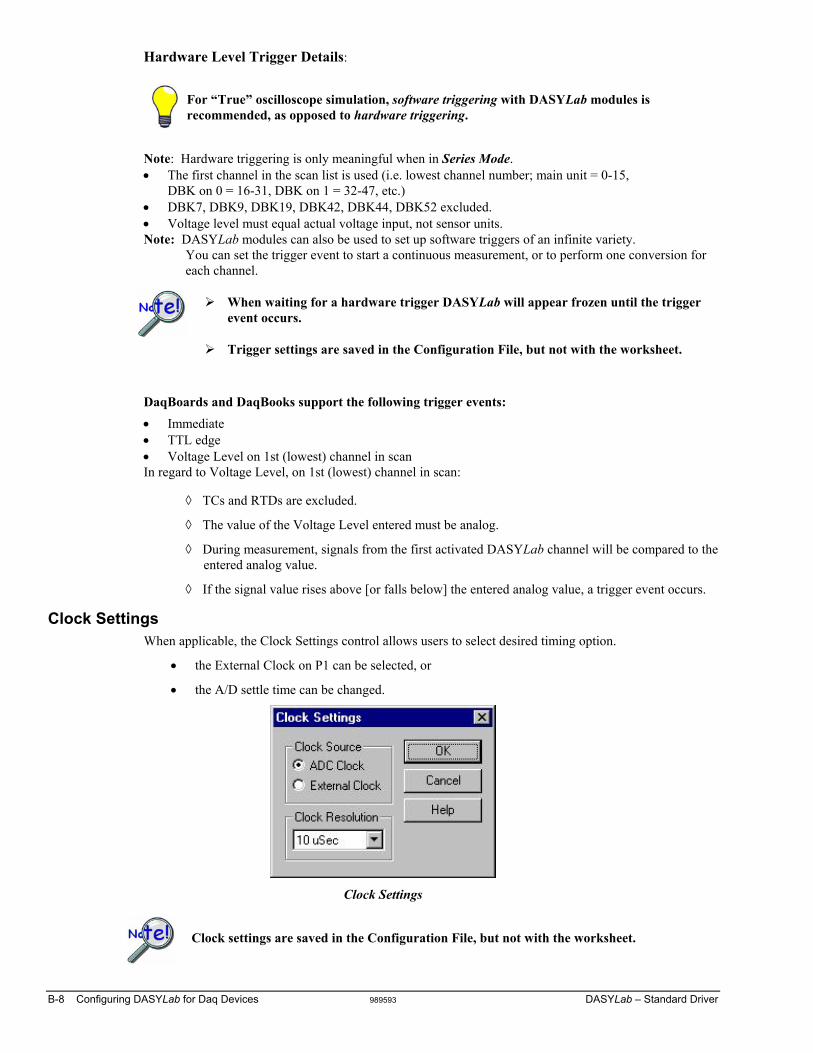
B-8 Configuring DASYLab for Daq Devices 989593 DASYLab – Standard Driver
Hardware Level Trigger Details:
For “True” oscilloscope simulation, software triggering with DASYLab modules is recommended, as opposed to hardware triggering.
Note: Hardware triggering is only meaningful when in Series Mode. • The first channel in the scan list is used (i.e. lowest channel number; main unit = 0-15,
DBK on 0 = 16-31, DBK on 1 = 32-47, etc.) • DBK7, DBK9, DBK19, DBK42, DBK44, DBK52 excluded. • Voltage level must equal actual voltage input, not sensor units. Note: DASYLab modules can also be used to set up software triggers of an infinite variety.
You can set the trigger event to start a continuous measurement, or to perform one conversion for each channel.
When waiting for a hardware trigger DASYLab will appear frozen until the trigger event occurs.
Trigger settings are saved in the Configuration File, but not with the worksheet.
DaqBoards and DaqBooks support the following trigger events: • Immediate • TTL edge • Voltage Level on 1st (lowest) channel in scan In regard to Voltage Level, on 1st (lowest) channel in scan:
◊ TCs and RTDs are excluded.
◊ The value of the Voltage Level entered must be analog.
◊ During measurement, signals from the first activated DASYLab channel will be compared to the entered analog value.
◊ If the signal value rises above [or falls below] the entered analog value, a trigger event occurs.
Clock Settings When applicable, the Clock Settings control allows users to select desired timing option.
• the External Clock on P1 can be selected, or
• the A/D settle time can be changed.
Clock Settings
Clock settings are saved in the Configuration File, but not with the worksheet.

DASYLab – Standard Driver 989593 Configuring DASYLab for Daq Devices B-9
Waveform Output (for Daq Devices with Analog Output DACs) Waveform Output applies to Daq Devices that have Digital-to-Analog Converters (DACs). The DACS could be built in to the device, or, in certain cases, be added to the device via a DBK46. When applicable, this feature enables waveform output (streaming) from the DACs and/or the P3 digital port. Selected channels are placed into waveform mode, while those not selected remain in direct output mode (P3 Digital could also be input) and can be accessed via the standard D/A module.
Notes Regarding Waveform Output:
• When using Waveform Output there is no additional module placed onto the worksheet. • Waveform output start is synchronized to the ADC trigger (acquisition start). • Waveforms continue to output until the worksheet ends. • In series mode the waveforms restart each series. • If ADC clock is selected as the source then each output update is synchronized with an analog scan
Waveform settings are saved in the Configuration File, but not with the worksheet.
Data Source: Direct Setup In this mode, 1 wavelength per channel is created as specified. The Frequency of the actual waveforms are Clock Frequency / Waveform Length. The Waveform Length multiplied by the number of enabled channels must be less than 100,000.
Waveform Output Control, Direct Setup
Data Source: From File The From File data source must contain only interleaved data for the exact number of enabled channels. The file will play out repeatedly. You can specify a section of the file via Header Offset Bytes and the Number of File Updates to Use (aggregate), or the entire file can be used.

B-10 Configuring DASYLab for Daq Devices 989593 DASYLab – Standard Driver
Waveform Output Control, From File
Waveform settings are saved in the Configuration File, but not with the worksheet.

DASYLab – Standard Driver 989593 Configuring DASYLab for Daq Devices B-11
DBK Card Configuration
Note: DaqBoard/1000 Series devices do not support DBK options. For DASYLab to properly operate DBK modules, they must be configured through the Hardware Configuration dialog box. Also each DBK card connected must have its jumpers/switches properly set to match the configuration.
Reference Note: Consult the hardware manual (p/n 457-0901) in regard to connecting, configuring, and powering each DBK card or module.
1. Click on Experiment and Hardware Setup or the Circuit board tool in the toolbar to open the Hardware Configuration dialog box.
2. To add Analog DBK cards, double click on the Analog Inputs card branching off the main unit. The card will expand into 16 connectors for the analog inputs.
Hardware Configuration Dialog Box
3. Click on the first available connector (0:) and then click on Properties. A dialog box appears with a list of installed expansion channels (if applicable).
Expansion Selection Dialog Box

B-12 Configuring DASYLab for Daq Devices 989593 DASYLab – Standard Driver
4. Click on the Select button (previous figure). An Expansions dialog box (following figure) appears with a list of DBK cards that are available for the particular channel. Scroll through the selections and highlight the card that is in your system, then click the OK button.
Expansions Dialog Box, Selecting a DBK84
5. If the expansion card you selected can have multiple cards on the same main unit channel (like the DBK4, 17, or 43), then:
(a) Adjust the Number of Devices in the Installed area of the Expansion Selection dialog box [see figure in step 3]. Set the number equal to the number of cards you will have on the same main unit channel. (b) Click the <OK> button.
Reference Note: DBK19 and DBK52 users need to refer to Appendix C.
6. Repeat the process for any remaining cards as needed.
DBK expansion cards must be installed sequentially without gaps.
DASYLab stores all the details concerning the hardware setup including DBK options that are in the Configuration File (but not with the worksheet). The worksheet file contains the name and path of the configuration file. If this file is deleted the worksheet may not load correctly. If a worksheet contains more channels than are configured (via DBKs) it will not load. If you have a worksheet that will not load, increase the number of DBK options installed until it loads.

DASYLab – Standard Driver 989593 Configuring DASYLab for Daq Devices B-13
Digital DBK Expansion
Note: DaqBoard/1000 Series devices do not support DBK options. The DBK digital expansion option cards must be configured sequentially, just like analog expansion cards. Since the various boards have differing bit counts and addressing, great care must be taken when installing these options.
For ISA and Parallel Port-based Daq devices, digital input on P2 requires that the P3 High-Speed Inputs be disabled.
Hardware Configuration Digital Inputs
Add the digital DBK modules to the empty connector in the “Programmable I/O Lines” section. Add them in order of largest to smallest channel count (DBK20/21 then DBK23/24 then DBK25s). Then adjust the switches on the DBK cards such that the addresses are sequential.
Configure Digital DBK expansion cards from largest channel count down; for example:
DBK20/21 ⇒ DBK23/24 ⇒ DBK25
Note that these settings are saved in the Configuration File, but not with the worksheet.
Note that during the configuring process, you will see the correct address setting for each DBK card. Good and bad setup examples follow.

B-14 Configuring DASYLab for Daq Devices 989593 DASYLab – Standard Driver
Setup Examples Good • DBK20 set to A • DBK23 set to 2 • DBK25 set to 12
Hardware Configuration – Example of a Good Setup

DASYLab – Standard Driver 989593 Configuring DASYLab for Daq Devices B-15
Supplemental Information Some of the material presented in this section is redundant. The material is included to provide a better understanding of hardware setup through use of screen images.
Using P1 Analog Inputs and DBK Signal Conditioning An example using a DaqBoard/2000 and a DBK9
1. Select Experiment ⇒ Hardware setup. This displays the current setup of the hardware
2. Double click the Analog Inputs icon for the device. Connector images appear, each image represents one single-ended analog input on the P1 port.
3. To place a DBK module on a P1 Analog Input connector:
(a) Double-click the applicable connector image (such as “0”).
(b) Click the Select button.
(c) Select the desired DBK module from the list provided. If DBK9 were selected we would end up with a screen image similar to that shown in the following figure.
When adding a DBK module, the DBK modules must be added in sequential order with no gaps.
Double-Clicking on the “DBK9: 0” will allow you to configure the card
All sub-addresses of a base system channel must be occupied, regardless of whether or not a DBK is actually present. If this is not performed, the program will not properly handle communication with cards on higher address numbers.
For example, when using a DBK9, an 8-channel card, you must select “2” as the number of devices, even if you are using only one DBK9. (See following figure).
A single icon handles all cards within the same base address so you need to exercise care in matching the icon software channel to the hardware sub-address and channel.

B-16 Configuring DASYLab for Daq Devices 989593 DASYLab – Standard Driver
When using a DBK9, an 8-channel card, you must select 2 as the number of devices.
After adding all of your DBK cards to your hardware setup, add your analog input modules to your worksheet as follows:
1. On your DASYLab Worksheet, go to Modules, then Analog Input. A selection menu that lists all hardware devices will appear.
2. After a module is added to the worksheet, double-click on it. In this example we have double-clicked on the “DBK9:0 AI” module icon. The following screen image resulted.
Setting Channel at Connector 0 as an RTD
3. Activate desired channels by left-button clicking them. Note that a single right-click deactivates the channel.
4. Click the Channel Setup button (see previous figure) to make channel setup selections. Note that conversion of voltage units to engineering units can be made using the channel scaling within the analog input module or the scaling module outside the analog input module. After completing your hardware setup, you are ready to add icons to your worksheet.
Reference Note: DBK19 and DBK52 users need to refer to Appendix C.

DASYLab – Standard Driver 989593 Configuring DASYLab for Daq Devices B-17
Worksheet Operations for Analog Input To add an analog input to your worksheet:
1. Select Modules ⇒ Input/output ⇒ Analog Input. Select the desired data acquisition device [or DBK module] from the list.
Selecting a Data Acquisition Device
2. Double-click the icon to view and/or modify its channel parameters.
A/D Icon for DBK19:0 Analog Input
The row of connector images, near the top of the window, represent available channels. Double-click a connector to enable (turn on) the associated channel. A single right click will disable a channel.
Click the channel setup button to make channel setup selections. Conversion of voltage units to engineering units can be made using the channel scaling within the analog input module or the scaling module outside the analog input module. See the DASYLab manual for details.
Analog Input Module – Connector 3 Selected
Enabled
Disabled

B-18 Configuring DASYLab for Daq Devices 989593 DASYLab – Standard Driver
Using P2 Digital I/O
If only the on-board P2 digital I/O is being used, no further configuration steps are required.
When applicable to a Daq device, to use digital DBK expansion options:
1. Double click the 40 Digital I/O lines icon within the Hardware setup window. 2. Double click the only available connector. 3. Click the Select button to view the available options.
When using cards with different channel counts, arrange the cards so that cards with more channels appear at lower address than cards with lesser channels. In other words, DBK20/21, then DBK23/24, then DBK25.
Reference Note: Refer to DASYLab’s on-line help for detailed configuration examples.
After completing your hardware setup, you are ready to add icons to your worksheet.
Communication with digital input ports is performed in a synchronous fashion.
Communication with digital output ports is performed in an asynchronous fashion.
Reference Note: More information regarding Synchronous and Asynchronous channels can be found on page B-22 of this document.
Using P3 DAC Output and P3 Digital Port Control - A DaqBoard/2000 Example This example applies to DaqBoard/2000, /2001, /2003, /2005.
This example applies to DaqBook/2000 Series devices, but only if a DBK46 Analog Output card is installed in that device.
1. Open the Hardware Setup window. 2. Click the Waveform button. This displays the configuration menu. 3. Select the desired item(s) for use with the waveform outputs
• DAC0 • DAC1 • P3 digital ports
Selecting DACs or the P3 port in Waveform Output Control (see following figure) prohibits their use for analog output control or digital output control. Use this window to configure waveform type, frequency, and amplitude for the respective hardware choices.

DASYLab – Standard Driver 989593 Configuring DASYLab for Daq Devices B-19
Waveform Output Control Window with
DACO, DAC1, P3 and Digital Channels Selected
To use the DACs for programmed control, place an analog output icon on your worksheet by selecting Modules ⇒ Input/Outputs ⇒ Analog Output.
The analog output icon provides the ability to connect software control icons to the channels, as long as the DACs have not been selected for waveform control.
Using P3 Counter Inputs
Because the communication with the P3 devices is synchronous, using a P3 counter is simply a matter of adding the counter input icon to your worksheet. Within that icon, you have the ability to configure the counters as four 16-bit counters, or as two 32-bit counters by making a selection in the Channel Setup window.
P3 counters can be configured to:
• count pulses • totalize pulses • calculate a frequency measurement

B-20 Configuring DASYLab for Daq Devices 989593 DASYLab – Standard Driver
General Experiment Setup The Experiment Setup regulates the general operation of the programmable hardware. These parameters affect the underlying performance of the A/D block at run-time.
To open the dialog box, select “Experiment ⇒ Experiment Setup.” Note that you can also open the dialog box by clicking on the A/D icon in the toolbar.
Experiment Setup Window
There are five sections in the Experiment Setup window. Of these, only Global Settings and Driver Settings are used with IOtech hardware.
Global Settings Sampling Rate – determines how fast the scans will be read
Block Size – determines how incoming data will be processed
Synchronization – sets the method of regulating system pacing
Sampling Rates Device
Time Between Channel Scans
DaqLab Devices DaqScan Devices DaqBoard/1000 and /2000 Series DaqBook/2000 Series
5 µs, 10 µs, or 1000 µs
Daq ISA-Type Devices 10 µs TempBook 10 µs WaveBook 1 µs

DASYLab – Standard Driver 989593 Configuring DASYLab for Daq Devices B-21
Card Setup and Clock Settings Windows
For example: If at 10 uSecs apart: if the Sampling Rate is set to 100Hz and there are 10 channels being read, then the 10 channels will be read in 100 uSec. 10 mSec later, they will be read again. The time between each channel read is fixed. The time between each scan read is adjustable using the Sampling Rate.
Block Size The Block Size determines how DASYLab will process the incoming data. DASYLab processes data n samples at a time (n samples = 1 block). With a block size of 512, five hundred and twelve samples will be collected before DASYLab processes any data. For slow acquisitions, this may be considered too long.
As a rough rule of thumb, large block sizes are suitable for high speed measurements small block sizes lead to short response times and are better suited for asynchronous output and online visualization.
Use small block sizes for slow acquisitions and large block sizes for faster acquisitions (1Hz, block size of 1; 20kHz, block size of 2048).
Sampled data can be transferred between the device and the PC in blocks of 2048 values each, or each sample can be transferred individually. In order to provide maximum performance and online visualization facilities, the appropriate transfer block size is selected automatically by the software.
Because DASYLab has to split computation time for the different actions performed, the block size specified in DASYLab defines how many samples are processed by DASYLab in a time-step.

B-22 Configuring DASYLab for Daq Devices 989593 DASYLab – Standard Driver
Synchronization Each IOtech device makes use of its own internal pacer clock to regulate system pacing, also referred to as synchronization. Some manufacturers permit the use of the PC’s internal clock for synchronization. Note that IOtech hardware pacers are more accurate than PC clocks.
Synchronous Channels are those that are scanned at the same point in time. These include:
• All analog input channels (local and DBK) • The P3 digital channel
In addition to the above two channel types most Daq devices include the following synchronous channels:
• P2 digital (local or DBK) • Counter inputs • Waveform output when ADC clock source selected.
Asynchronous Channels are read or updated independently. This occurs at the block interval while DASYLab processes data. Their timing is generally regular but is based on processing speed and can not be guaranteed. Asynchronous channels include:
• All digital outputs • P2 digital inputs on DaqBook/100 Series, /200 Series, and DaqBoard/100 Series, and /200 Series • Direct voltage outputs (Waveform excluded) • Timer output (F Out) changes.
Note: DASYLab updates the outputs between the completed scans of the analog input channels at the end of a block interval. The smaller the block size the more often the output.
For proper operation of DBK2 and DBK5, you must set the Acquisition Mode to Running or Isolated Series rather than the typical, Continuous mode. This selection is made in the “Experiment Setup” window.
Since direct analog outputs are asynchronous, they are typically not well suited for real-time waveform generation or fast process control.
For variable-frequency square-wave generation, use the frequency output module.
Care must be taken when mixing synchronous and asynchronous channels. Please ensure all channels have the same block size and sample interval when sharing a DASYLab analysis, display, or file module.

DASYLab – Standard Driver 989593 Configuring DASYLab for Daq Devices B-23
Driver Settings The Buffer Size sets the size of DASYLab's buffer. This buffer is made up of a block of the computer's memory. As a background activity, DASYLab continuously collects data from the acquisition device at the programmed acquisition rate and places the data into its internal data buffer for processing. This ensures gapless data under all conditions. Data is stored here until DASYLab can process it.
The status of this buffer is shown (in bar-graph format) in the bottom right corner of the DASYLab window. If DASYLab is unable to process the data as fast as it is being collected, the bar graph will begin to fill red. If DASYLab's buffer completely fills, a buffer overrun error will be encountered.
The Acquisition Mode determines how DASYLab will acquire data.
In Continuous Mode, DASYLab acquires data indefinitely without breaks.
Running Series:
• acquires the number of blocks specified in Blocks Per Series • pauses for the number of seconds in Delay(Sec) • repeats the process
The pauses are ignored and the data is seen as continuous.
Isolated Series is the same as Running Series, except the delays are recorded.
One Series acquires the specified number of blocks, then stops.
For DBK2 and DBK5 applications, Series Mode must be used with Pre-Trigger enabled.

B-24 Configuring DASYLab for Daq Devices 989593 DASYLab – Standard Driver
This page is intentionally blank.

Appendix C 958095 Cal Notes for DBK19, DBK52, and TemBook/66 C-1
Appendix C Cal Notes for DBK19, DBK52, and TempBook/66 TempBook/66, DBK19, and DBK52 users may wish to use the software calibration file for thermocouple measurements. To select a file, click on the Calibration button. You will be warned if the file does not exist or contains invalid values. DBK19 and DBK52 channels will only use the calibration file if the <Use calibration functions> is checked in the DBK Expansion dialog for each DBK card.
The calibration file needs to be configured and located on your hard drive. Refer to the documentation included with the DBK modules.
To specify the location of the calibration file, double click your acquisition device in the hardware configuration tree, then click <Calibration File>.
Accessing the DBK19/DBK52 Calibration File
To make use of the calibration file:
1. Double-click the DBK19 or DBK52 in the hardware configuration tree, as applicable.
Example of Selecting the Calibration Function for use with DBK19
2. Click the Use Calibration Function check box.
These settings are saved in the Configuration File, but not with the worksheet.

C-2 Cal Notes for DBK19, DBK52, and TemBook/66 958095 Appendix C