Embed Size (px)
Citation preview

LRIT/HRIT SystemReliable, high performance solution for receiving,archiving, processing and displaying LRIT and HRITdata from EUMETCast, HimawariCast, MSG, GOES,COMS-1 and Electro services
The Dartcom LRIT/HRIT System canreceive, archive, process and displayLRIT and HRIT data from EUMETCast,HimawariCast, MSG direct broadcast,GOES, COMS-1 and Electro services.
LRIT and HRIT data is an important source ofinformation for nowcasting, numerical weatherprediction, climate monitoring and research. Thelatest imagery and products are available asfrequently as every 15 minutes, allowing majorimprovements in the forecasting of severe weather.
Antenna and receiver options are available to suitdifferent services, geographical locations andrequirements. All types of transmission aresupported – Ku-Band and C-Band DVB services,and L-Band direct broadcast services.
Ingested data can be viewed and processed usingthe Dartcom iDAP/MacroPro software. Outputsare also available for popular image processingsoftware packages such as PCI Geomatica, ERDASIMAGINE and ENVI/IDL, as well as standardinterchange formats such as GeoTIFF.
πMeteosat 10 HRIT and Electro-L LRIT false colour images showing weather systems inthe Atlantic, and snow and cloud over the Himalayas
πDartcom 1.2m Ku-Band antenna
LRIT/HRIT System Overview
πDartcom iDAP and MacroPro software πDartcom XRIT Ingester software
Components• Antenna – various sizes available, or customers can source their
own locally, or upgrade a disused WEFAX antenna if suitable.
• Receiver – various options available to suit different services.
• Ingest and visualisation PC – running Dartcom XRIT Ingesterand Dartcom iDAP/MacroPro software. Customers can eithersupply their own PC, or for a turnkey solution Dartcom cansupply a PC fully set-up and tested.
Dartcom can also provide on-site installation and training services.
Features• Fully automatic reception, decryption, decompression, archiving,
output and processing of LRIT and HRIT data.
• All current services supported, including EUMETCast LRIT, HRITand SAF, HimawariCast LRIT and HRIT, MSG direct broadcastLRIT, GOES LRIT, COMS-1 LRIT and HRIT, and Electro-L LRIT.
• Simple hardware installation with little or no civil engineeringworks required in most cases.
• Advanced multi-threaded software architecture allowing ingestfrom multiple services simultaneously.
• Proven, robust, reliable hardware and software, with installationsall over the world in all climates, temperatures and environments.
• Comprehensive hardware and software diagnostics at all levels,with on-screen and email alarms, and full logging if required.
• Can be integrated with the Dartcom HRPT/AHRPT System toprovide a full polar-orbiter and geostationary reception station.
Software• Dartcom XRIT Ingester – provides automatic ingest, archiving
and output of LRIT and HRIT data.
• Dartcom iDAP – provides a wide range of image manipulationand processing facilities such as animation, enhancement,product creation, reprojection, masking, printing and exportingto third-party formats such as PCI Geomatica, ERDAS IMAGINE,ENVI/IDL and GeoTIFF.
• Dartcom MacroPro – automates the powerful processingfacilities provided by iDAP.
πDartcom 1.2m L-Band antenna installed at theUniversity of Huaraz in Peru
πDartcom 3.0m L-Band antenna

π 1.8m Ku-Band antenna
Ku-Band hardware LRIT/HRIT System
1.8m antenna
Offset
Glass-fibre reinforced polyester
1.8m
0.66
45.5dBi
Linear
26.0dB/K
72km/h operational
201km/h survival
Ku-Band hardwareRequired for Ku-Band EUMETCast LRIT/HRIT reception. See theService availability section for coverage.
85cm, 1.2m or 1.8m offset dish and LNB
• High-quality powder-coated aluminium (85cm, 1.2m) or glass-fibre reinforced compression moulded polyester (1.8m) reflector.
• 2.4–4.5m antennas also available for fringe area reception.
• Supplied with azimuth/elevation mounting bracket (85cm, 1.2m),50m of CT100 75 co-axial cable and F-type connectors.
• 1.8m antenna supplied with 4” tubular pedestal (optional non-penetrating roof mount also available).
• State-of-the-art weatherproof LNB with a noise figure of 0.3dB.
DVB receiver and software
• Ayecka SR1 (desk or 19” rack mount) or TBS 6983 (PCIe card)DVB-S2 receiver, both recommended by EUMETSAT.
• Supplied with drivers and T-Systems Business TV-IP software.
π 85cm Ku-Bandantenna
πAyecka SR1 DVB-S2 receiver, rack mount version
πAyecka SR1 DVB-S2 receiver, desk mount version®TBS 6983 PCIe DVB-S2 receiver card
† Colour availabilities for Ku-Band dish antennas
Size
85cm
1.2m
1.8m
Slate grey
�
Beige
�
Brick red
�
Light grey
�
�
† Ku-Band antenna specifications
Reflector type
Reflective material
Reflector diameter
F/D ratio
Gain
Polarisation
G/T @ 5˚ elevation
Wind speeds
85cm antenna
21˚ offset
Solid aluminium, powder coated
0.85m
0.67
38.2dBi
Linear
17.2dB/K
80km/h operational
120km/h survival
1.2m antenna
21.3˚ offset
Solid aluminium, powder coated
1.2m
0.66
41.3dBi
Linear
19.2dB/K
80km/h operational
120km/h survival
† Ayecka SR1 DVB-S2 receiver specifications
RF input frequency
RF input connector
Symbol rates
Channel rate
950–2150MHz
75 F-type
100ksps to 45Msps
Up to 120Mbps
†TBS 6983 PCIe DVB-S2 receiver card specifications
RF input frequency
RF input connector
Symbol rates
Channel rate
950–2150MHz
75 F-type
1Msps to 45Msps
Up to 190Mbps
† Ku-Band LNB specifications
Feed type
Polarisation
RF input
Noise figure
Total gain
LO frequency
RF output
Scalar horn
Linear
10.7–12.75GHz
0.3dB typical
50–60dB
Low: 9.75GHz
High: 10.6GHz
950–2150MHz

LRIT/HRIT System C-Band hardware
πTechniSatSkyStar 2 receiver card
πTBS 6983 PCIe DVB-S2receiver card
C-Band hardwareRequired for C-Band EUMETCast LRIT/HRIT and HimawariCastLRIT/HRIT reception. See the Service availability section for coverage.
2.4m, 3.0m or 3.7m parabolic dish and LNB
• Three-segment (2.4m) or eight-segment (3.0m, 3.7m) glass-fibrereinforced precision compression moulded polyester reflector.
• Supplied with galvanised steel azimuth/elevation mount andpedestal, and 50m of CT100 75 co-axial cable.
• Phase locked loop LNB in weatherproof powder-coated housing.
DVB receiver and software
• TechniSat SkyStar 2 internal PCI DVB receiver card for EUMETCast.
• TBS 6983 internal PCIe DVB-S2 receiver card for HimawariCast.
• Supplied with drivers and data acquisition software (Tellicast forEUMETCast, KenCast FAZZT for HimawariCast).
π 3.0m/3.7m C-Band dish antenna and LNB
π 2.4m C-Band dish antenna and LNB
π C-Band LNB† C-Band antenna specifications
Reflector type
Reflective material
Reflector diameter
F/D ratio
Gain
Polarisation
G/T @ 5˚ elevation
Wind speeds
3.7m antenna
Prime focus parabolic
8-segment glass-fibre reinforced
polyester
3.7m
0.37
40.9dBi
Circular
21.7dB/K
72km/h operational
201km/h survival
2.4m antenna
Prime focus parabolic
3-segment glass-fibre reinforced
polyester
2.4m
0.37
37.5dBi
Circular
17.7dB/K
80km/h operational
201km/h survival
3.0m antenna
Prime focus parabolic
8-segment glass-fibre reinforced
polyester
3.0m
0.30
40.0dBi
Circular
19.8dB/K
72km/h operational
201km/h survival
†DVB receiver specifications
RF input
frequency
RF input
connector
Symbol rates
Data rates
SkyStar 2
950–2150MHz
75 F-type
2Msps to 45Msps
Up to 90Mbps
† C-Band LNB specifications
Feed type
Polarisation
RF input
Noise figure
Total gain
RF output
Scalar horn
Circular
3.4–4.2GHz
0.35dB typical
>60dB
950–1750MHz
TBS 6983
950–2150MHz
75 F-type
1Msps to 45Msps
Up to 190Mbps

® L-Band scalar feed (3.7m antenna)
† L-Band antenna specifications
L-Band antennas LRIT/HRIT System
L-Band hardwareRequired for L-Band direct broadcast MSG LRIT, GOES LRIT,LRIT/HRIT, COMS-1 LRIT/HRIT and Electro LRIT/HRIT reception.See the Service availability section for coverage.
1.2m, 1.8m, 2.4m, 3.0m or 3.7m parabolic dish
• Solid powder-coated aluminium (1.2m, 1.8m) or glass-fibrereinforced precision compression moulded polyester reflectorwith three segments (2.4m) or eight segments (3.0m, 3.7m).
• Supplied with galvanised steel azimuth/elevation mount andpedestal, and up to 100m of RG213 50 co-axial cable.
Feed and downconverter
• Integrated feed/downconverter (1.2m, 1.8m, 2.4m, 3.0m) orscalar horn (3.7m) with N-type output.
• LNA/downconverter designed for harsh radio environments withpre-select filter to reduce cellular phone and radar interference.
• Low noise figure of 1.2dB (92K) typical.
• Weatherproof O-ring sealed machined case and connectors.
† L-Band feed and downconverter specifications
Feed type
Polarisation
RF input
LNA noise figure
Pre-LNA filter
Total gain
LO frequency
RF output
PCB patch IFD (1.2/1.8/2.4/3.0m)
Scalar horn (3.7m)
Linear (RHC for Electro)
1691MHz ±25MHz
1.2dB typical
3-pole, –3dB ±60MHz
>50dB
1553.5MHz
137.5MHz ±25MHz
π 3.0m/3.7m L-Band dish antenna and LNB
π 1.2m/1.8m/2.4m L-Band dish antenna and LNB
π L-Band downconverter
Reflector type
Reflective material
Reflector diameter
F/D ratio
Gain
Polarisation
G/T @ 5˚ elevation
Wind speeds
3.0m antenna
Prime focus
parabolic
8-segment glass-
fibre reinforced
polyester
3.0m
0.30
32.2dBi
Linear
11.7dB/K
72km/h operation
201km/h survival
3.7m antenna
Prime focus
parabolic
8-segment glass-
fibre reinforced
polyester
3.7m
0.37
34.1dBi
Linear
13.5dB/K
72km/h operation
201km/h survival
1.8m antenna
Prime focus
parabolic
Solid aluminium,
powder coated
1.8m
0.42
27.5dBi
Linear
6.0dB/K
112km/h operation
201km/h survival
1.2m antenna
Prime focus
parabolic
Solid aluminium,
powder coated
1.2m
0.38
24.0dBi
Linear
2.2dB/K
112km/h operation
201km/h survival
2.4m antenna
Prime focus
parabolic
3-segment glass-
fibre reinforced
polyester
2.4m
0.37
30.3dBi
Linear
9.6dB/K
80km/h operation
201km/h survival

LRIT/HRIT System L-Band receivers
USB LRIT/HRIT receiver rack
• High quality, high performance, professional grade receiver fordirect broadcast LRIT and HRIT transmissions from MSG, GOESand COMS-1 services.
• Available in LRIT, HRIT or combined LRIT/HRIT configurations.
• Rugged 4U-high 19” rack.
• Plug-in modules for ease of maintenance and to allow for futureupgrades.
• USB interface for fast, reliable data transfer to the host computer.
• Fully software controlled, with detailed status reports available.
• Comprehensive LED and character matrix status displays anddiagnostic points on the front panel.
• Supplied with up to two state-of-the-art multi-mode DSP receivermodules and USB interface modules.
• Each receiver module supplies power to the LNB via its RF input.
• Supports QPSK, BPSK and PSK demodulation.
• Built-in hardware Viterbi decoding.
• Rack or desk mount versions available.
• Powered by 100–240V AC mains, 50–400Hz.
• Upgradable to also provide HRPT/AHRPT reception by purchasingadditional plug-in modules together with a tracking antennasystem and Dartcom Polar Orbiter Ingester software.
USB LRIT receiver
• High-quality, low-cost receiver for direct broadcast LRITtransmissions from MSG, GOES, COMS-1 and Electro services.
• Fully compatible with the forthcoming GOES-R HRIT service.
• Housed in a sleek, compact, durable extruded aluminium casewith styled ABS bezels.
• USB interface for fast, reliable data transfer to the host computer.
• Fully software controlled, with detailed status reports available.
• Built-in time-stamped fault logging.
• 20-LED real-time signal level display for easy dish alignment andoperational signal monitoring.
• Status LEDs for LNB power, signal lock, USB ready, controlcommunications, data buffer status and frame synchronisationdetection.
• Adjustable RF attenuator to accommodate LNB signal inputsbetween –15dBm and –75dBm.
• Supports QPSK and BPSK demodulation.
• Built-in hardware Viterbi decoding.
• Supplies power to the LNB via the RF input.
• Powered by an external switch mode PSU (supplied).
• DC–DC converter PSU also available for battery or portableoperation (input 10.6–15V DC).
πDartcom USB LRIT/HRIT receiver rack† Specifications
πDartcom USB LRIT receiver† Specifications
RF input frequency
RF input connector
IF conversion
Frequency resolution
Symbol rates
Viterbi decoding
Demodulator modes
Data encodings
Performance
Digital interface
Power requirements
126–154MHz
50 N-type
Direct, 70MHz, 50MSPS, 10-bit
25kHz
0.1Msps to 3.5Msps
1⁄2, K=7, G1=171, G2=133, 5.2dB
coding gain at 1:105 BER
QPSK, BPSK, PSK
NRZ, NRZ-S, NRZ-M, Biphase-L
QPSK/BPSK within 1dB of
theoretical, 0.5dB typical
USB port
100–240V AC 50–400Hz
RF input frequency
Frequency resolution
RF input connector
RF input level
Symbol rates
Viterbi decoding
Demodulator modes
Data encodings
Digital interface
Power requirements
LNB power
PSU
Dimensions (W H D)
Weight
135–144MHz
(1688.5–1697.5MHz from a
1691MHz to 137.5MHz LNB)
5kHz
50 BNC
–15dBm to –75dBm
64ksps to 1024ksps
1⁄2, K=7, G1=171, G2=133
QPSK, BPSK
NRZ-S, NRZ-M, NRZ-L
USB port
15V DC @ 2A
14–15V DC nominal @ 0.75A
via RF input
External switch mode, input
100–240V AC 47–63Hz @ 1.2A
175 60 240mm
1.7kg (including PSU)

Service availability LRIT/HRIT System
π EUMETCast Ku-Band basic service availability – 85cm antenna (G/T @ 12.5GHz = 18.5dB/K)
π EUMETCast Ku-Band basic service availability – 1.2m antenna (G/T @ 12.5GHz = 20.5dB/K)
π EUMETCast Ku-Band basic service availability – 1.8m antenna (G/T @ 12.5GHz = 23.5dB/K)
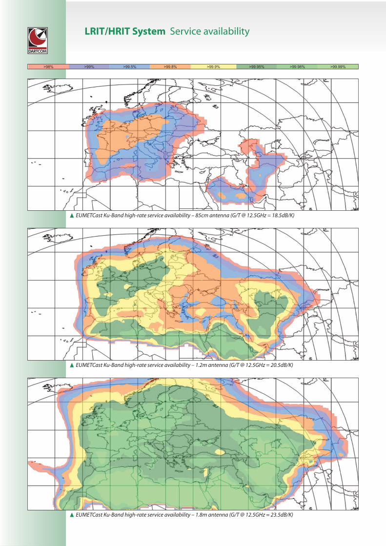
LRIT/HRIT System Service availability
π EUMETCast Ku-Band high-rate service availability – 85cm antenna (G/T @ 12.5GHz = 18.5dB/K)
π EUMETCast Ku-Band high-rate service availability – 1.2m antenna (G/T @ 12.5GHz = 20.5dB/K)
π EUMETCast Ku-Band high-rate service availability – 1.8m antenna (G/T @ 12.5GHz = 23.5dB/K)

Service availability LRIT/HRIT System
π EUMETCast Ku-Band high-rate service availability – 2.4m antenna (G/T @ 12.5GHz = 26.0dB/K)
π EUMETCast Ku-Band high-rate service availability – 3.7m antenna (G/T @ 12.5GHz = 28.9dB/K)
π EUMETCast Ku-Band high-rate service availability – 4.5m antenna (G/T @ 12.5GHz = 31.5dB/K)

LRIT/HRIT System Service availability
π EUMETCast C-Band service availability
πGOES East L-Band coverage, centred on 75˚W –1.2m antenna required
πGOES West L-Band coverage, centred on 135˚W – 1.2m antennarequired

Service availability LRIT/HRIT System
πMSG LRIT L-Band direct broadcast service availability – 1.8m antenna required

Powdermills, Postbridge, Yelverton, Devon, PL20 6SP, UKPhone (01822) 880253 • International +44 1822 880253Web www.dartcom.co.uk • Email [email protected]
Copyright © 2015 Dartcom. Dartcom reserves the right to change specifications without notice. Pictures are for illustrative purposes only.Correct from 12th June 2015. E&OE.
LRIT/HRIT System Service availability
0° 0°
1.8m C-Band system required
2.4m C-Band system required
πHimawariCast C-Band service availability
π COMS-1 L-Band coverage, centred on 128.2˚E – 1.2mantenna required for LRIT, 3.0m/3.7m for HRIT
π Electro-L L-Band coverage, centred on 76˚E – 1.8mantenna required for LRIT, 3.0m/3.7m for HRIT


![ReviewProlactinomas, Cushing's disease and acromegaly ... · microprolactinomas and 34% in patients with macropro-lactinomas [4]. Transcranial surgery is rarely performed, and is](https://img.pdfslide.us/doc/110x75/5bcb8f9b09d3f24a0c8bba5e/reviewprolactinomas-cushings-disease-and-acromegaly-microprolactinomas.jpg)