Embed Size (px)
Citation preview
Darmstadt University of Technology
Department of Electrical Engineering & Information TechnologyMerckstraße 25 • D-64283 Darmstadt • Germany
Phone: +49 6151 166150Fax: +49 6151 166152Email: [email protected]: http://www.kom.e-technik.tu-darmstadt.de/
Industrial Process and System Communications (KOM)
A Flexible, QoS-AwareIP/ATM Adaptation Module
Jens Schmitt
December 1999
Technical Report TR-KOM-1999-06
1
reas-ingnot yetg the
theiry net-iate
ed IP/ular,itecture
apta-ndingneces-asy tothe
sks oftation
onve-anism
A Flexible, QoS-Aware IP/ATMAdaptation Module
Jens Schmitt
Industrial Process and System CommunicationsDepartment of Electrical Engineering and Information Technology
Darmstadt University of TechnologyMerckstr. 25 • D-64283 Darmstadt • Germany
{Jens.Schmitt, Martin.Karsten, Lars.Wolf, Ralf.Steinmetz}@kom.tu-darmstadt.de
Abstract
Overlaying IP-based networks onto ATM subnetworks is a network configuration pattern found incingly often. While IP networks traditionally only offer plain "best-effort" service they are now evolvto offer more sophisticated services. Nevertheless, the exact mechanisms for providing QoS aresettled and essentially non-existing in today’s production-level networks, with the Internet beinmost popular and important example. On the other hand, ATM networks have been designed frominception to offer a wide range of QoS mechanisms. Thus, given the configuration of an IP overlawork over an ATM subnetwork, it is very attractive to leverage ATM’s QoS mechanisms to allevIP’s QoS problem, at least partially. The invocation of those mechanisms will be done on so-callATM edge devices which are exactly at the frontier between the IP and ATM network. In particthese edge devices could map reservation requests within the context of the RSVP/IntServ archonto especially setup VCs.
In this report we describe the design and implementation of a flexible, QoS-aware IP/ATM adtion module. This adaptation module allows an IP/ATM edge device to route IP datagrams depeon their contents onto especially setup VCs in a performant manner. To achieve performance it issary to implement this module in kernel space, at least partially. On the other hand, it should be euse, for e.g. an RSVP/IntServ over ATM, or a DiffServ over ATM mapping module. Therefore,adaptation module was split into two parts, a kernel-level part that handles all the time-critical tadata forwarding and a user-level part which gives access to the functionality provided by the adapmodule.
The result is a very flexible and general IP/ATM adaptation module that can be integrated cniently with earlier results of the project on approaches of how to map the RSVP/IntServ mechonto those of an ATM subnetwork.
This work is supported in part by a grant of Volkswagen-Stiftung, D-30519 Hannover, Germany.
2
Table of Contents
1 Introduction . . . . . . . . . . . . . . . . . . . . . . . . . . . . . . . . . . . . . . . . . . . . . . . . . 5
1.1 Motivation . . . . . . . . . . . . . . . . . . . . . . . . . . . . . . . . . . . . . . . . . . . . . . . . . . . . . . . . .5
1.2 Outline . . . . . . . . . . . . . . . . . . . . . . . . . . . . . . . . . . . . . . . . . . . . . . . . . . . . . . . . . . . .5
2 Architecture of the IP/ATM Adaptation Module . . . . . . . . . . . . . . . . . . . 7
2.1 Overview . . . . . . . . . . . . . . . . . . . . . . . . . . . . . . . . . . . . . . . . . . . . . . . . . . . . . . . . . .7
2.2 Design Goals . . . . . . . . . . . . . . . . . . . . . . . . . . . . . . . . . . . . . . . . . . . . . . . . . . . . . . .7
2.2.1 Problem-Specific Goals . . . . . . . . . . . . . . . . . . . . . . . . . . . . . . . . . . . . . . . .72.2.2 General Goals . . . . . . . . . . . . . . . . . . . . . . . . . . . . . . . . . . . . . . . . . . . . . . . .82.2.3 Secondary Goals . . . . . . . . . . . . . . . . . . . . . . . . . . . . . . . . . . . . . . . . . . . . . .9
2.3 Components and their Relations . . . . . . . . . . . . . . . . . . . . . . . . . . . . . . . . . . . . . . .10
2.4 Interface to the IP/ATM Adaptation Module . . . . . . . . . . . . . . . . . . . . . . . . . . . . .13
2.5 Functional Restrictions of the Current Implementation . . . . . . . . . . . . . . . . . . . . .13
2.6 System Requirements . . . . . . . . . . . . . . . . . . . . . . . . . . . . . . . . . . . . . . . . . . . . . . .14
3 The VCM Kernel Instance . . . . . . . . . . . . . . . . . . . . . . . . . . . . . . . . . . . . 15
3.1 Overview . . . . . . . . . . . . . . . . . . . . . . . . . . . . . . . . . . . . . . . . . . . . . . . . . . . . . . . . .15
3.2 Review of UNIX Device Drivers and the STREAMS Mechanism. . . . . . . . . . . . .15
3.2.1 UNIX Device Drivers . . . . . . . . . . . . . . . . . . . . . . . . . . . . . . . . . . . . . . . . .153.2.2 STREAMS Framework and Mechanisms. . . . . . . . . . . . . . . . . . . . . . . . . .16
3.3 Architecture of the Fore ATM Network Driver . . . . . . . . . . . . . . . . . . . . . . . . . . .19
3.4 Design Goals and Decisions . . . . . . . . . . . . . . . . . . . . . . . . . . . . . . . . . . . . . . . . . .20
3.5 Architecture of the VCM Kernel Instance. . . . . . . . . . . . . . . . . . . . . . . . . . . . . . . .21
3.6 Modules of the VCM Kernel Instance. . . . . . . . . . . . . . . . . . . . . . . . . . . . . . . . . . .23
3.6.1 Solaris Device Driver Specifics Module: vcm_ddi.c . . . . . . . . . . . . . . . . .233.6.2 VCM STREAMS Multiplexing Device Driver: vcm_dev.c. . . . . . . . . . . .233.6.3 VCM STREAMS Module: vcm_mod.c . . . . . . . . . . . . . . . . . . . . . . . . . . .263.6.4 Filter Configuration and Management Module: vcm_filter.c . . . . . . . . . . .283.6.5 Filter Rule Matching Module: vcm_rule.c . . . . . . . . . . . . . . . . . . . . . . . . .30
4 The VCM User Instance . . . . . . . . . . . . . . . . . . . . . . . . . . . . . . . . . . . . . . 32
4.1 Overview . . . . . . . . . . . . . . . . . . . . . . . . . . . . . . . . . . . . . . . . . . . . . . . . . . . . . . . . .32
4.2 Design Goals and Decisions . . . . . . . . . . . . . . . . . . . . . . . . . . . . . . . . . . . . . . . . . .32
4.3 Architecture of the VCM User Instance . . . . . . . . . . . . . . . . . . . . . . . . . . . . . . . . .33
4.3.1 Global View . . . . . . . . . . . . . . . . . . . . . . . . . . . . . . . . . . . . . . . . . . . . . . . .334.3.2 Static Model . . . . . . . . . . . . . . . . . . . . . . . . . . . . . . . . . . . . . . . . . . . . . . . .34
4.4 User Interface Layer Classes . . . . . . . . . . . . . . . . . . . . . . . . . . . . . . . . . . . . . . . . . .36
3
4.4.1 The Filter Class . . . . . . . . . . . . . . . . . . . . . . . . . . . . . . . . . . . . . . . . . . . . . .364.4.2 The FilterRule Class . . . . . . . . . . . . . . . . . . . . . . . . . . . . . . . . . . . . . . . . . .374.4.3 The VC Class . . . . . . . . . . . . . . . . . . . . . . . . . . . . . . . . . . . . . . . . . . . . . . .384.4.4 The PointToPointVC Class. . . . . . . . . . . . . . . . . . . . . . . . . . . . . . . . . . . . .394.4.5 The MultipointVC Class . . . . . . . . . . . . . . . . . . . . . . . . . . . . . . . . . . . . . . .404.4.6 The QoS Class. . . . . . . . . . . . . . . . . . . . . . . . . . . . . . . . . . . . . . . . . . . . . . .404.4.7 The AddrResolver Class . . . . . . . . . . . . . . . . . . . . . . . . . . . . . . . . . . . . . . .414.4.8 The SimpleAddressResolver Class . . . . . . . . . . . . . . . . . . . . . . . . . . . . . . .41
4.5 Kernel Interface Layer Classes . . . . . . . . . . . . . . . . . . . . . . . . . . . . . . . . . . . . . . . .41
4.5.1 The KernelIF Class . . . . . . . . . . . . . . . . . . . . . . . . . . . . . . . . . . . . . . . . . . .414.5.2 The UNIcontrol Class . . . . . . . . . . . . . . . . . . . . . . . . . . . . . . . . . . . . . . . . .424.5.3 The VCMcontrol Class . . . . . . . . . . . . . . . . . . . . . . . . . . . . . . . . . . . . . . . .43
4.6 Auxiliary Classes. . . . . . . . . . . . . . . . . . . . . . . . . . . . . . . . . . . . . . . . . . . . . . . . . . .43
4.6.1 The List Class . . . . . . . . . . . . . . . . . . . . . . . . . . . . . . . . . . . . . . . . . . . . . . .444.6.2 The SortedList Class . . . . . . . . . . . . . . . . . . . . . . . . . . . . . . . . . . . . . . . . . .454.6.3 The VCDVCTuple Class . . . . . . . . . . . . . . . . . . . . . . . . . . . . . . . . . . . . . .474.6.4 The AddrPartyIDTuple Class . . . . . . . . . . . . . . . . . . . . . . . . . . . . . . . . . . .47
4.7 Example of Use . . . . . . . . . . . . . . . . . . . . . . . . . . . . . . . . . . . . . . . . . . . . . . . . . . . .47
5 Summary . . . . . . . . . . . . . . . . . . . . . . . . . . . . . . . . . . . . . . . . . . . . . . . . . . 49
References. . . . . . . . . . . . . . . . . . . . . . . . . . . . . . . . . . . . . . . . . . . . . . . . . . . . 50
4
est IP-y usedargens, i.e.
blingch iseeded.
t
l forsub-
e dis-ations
con-em of
net-e code
of the
e for-risticst forllow
rvices
d. Weionale.terface
h work
th, itsture.ecture,cture.
1 Introduction
1.1 Motivation
IP-based production networks essentially still offer only best-effort service, and so does the largbased network - the Internet. However, the Internet is becoming or even already is a commerciallubiquitous communication infrastructure. A fact which will eventually require the Internet (or also lIP-based intranets) to be able to accurately predict its performance for business-critical applicatiodeliver stringent Quality of Service (QoS) guarantees for those applications.
On the other hand, the Asynchronous Transfer Mode (ATM) technology offers a lot of QoS-enafacilities. However, due to its homogeneity stipulation, it faces its degradation to a link layer whibeing used by TCP/IP in the core of the network where its accurate QoS mechanisms are most nThe result is:
IP lacks QoS, but has a wide distribution - ATM has QoS, but is not available end-to-end.Hence it seems very reasonable that IP takes ATM’s assist in order to provide QoS, so thaits huge user base can profit from ATM’s facilities without the need of introducing ATMend-to-end.
In previous reports ([SWS97a], [SKWS98]) of the IQATM project we used the term overlay modethat kind of operation for the special case when mapping the RSVP/IntServ architecture onto ATMnetworks.
In general, the problem of providing QoS in packet-switched networks can be separated into thtinct but related problems on the control and the data path. Previous prototypical implementwithin the project ([SWS97b], see also Appendix) mainly focused on solution approaches for thetrol path issues of the problem, while they used a very simple and inefficient solution for the problproviding QoS on the data path. That was due to the non-availability of source code of the ATMwork driver, which needs to be modified for that purpose. Now we have access to such sourc(thanks to the Fore partner’s programme) and thus it was decided to overcome the deficienciesprevious implementations on the data path.
Therefore we developed in a first step an IP/ATM adaptation module that allows to instruct thwarding path inside an IP/ATM edge device to "route" IP data flows according to some characteonto especially setup ATM VCs. While the adaptation module’s provided functionality is sufficienefficiently operating RSVP/IntServ on the data path, it is intentionally designed more flexible to afor other QoS-conveying information in IP datagrams (as e.g. contained in the Differentiated Se(DiffServ) byte) to be a source of special handling in the ATM network as well.
1.2 Outline
In the next chapter, the overall architecture of the IP/ATM adaptation module is being presenteprovide the design goals which lead the development of this adaptation module and give their ratThen a macroscopic view on the components of the adaptation module is given and the general into the adaptation module is described. The adaptation module consists of two instances whictogether:
• a kernel instance, and a• user instance.
In chapter 3, we describe the design and implementation of the kernel instance by looking at boglobal architecture and the functionality provided locally by the modules which form that architec
In chapter 4, details on the user instance are presented. Again we start by looking at its architbefore we go into the details of the implementation of the components which make up that archite
5
w to
refer-
In addition, we illustrate the application of the IP/ATM adaptation module by a short example of house it via the library interface provided by the user instance of the adaptation module.
In the last chapter, we provide a short summary of the report and give the relevant literatureences.
6
briefuitime wepment
nt com-ip withhortlyQoS
pter 4.unc-f this
c goalsapta-ving to
fcould
to:
ld be
re orta that
nge-
ffort
2 Architecture of the IP/ATM Adaptation Module
2.1 Overview
In this section we describe the architecture of the IP/ATM adaptation module. We start by giving aoverview of the function of that module, which will further on also be called VCM (Virtual CircManagement) module. We discuss its design goals and what it is aimed at, and at the same tpoint out what it is not, respectively what have been secondary goals during the process of develoand why some restrictions have been made. Following these discussions we present the differeponents of the VCM module and their relationships among themselves as well as their relationshexisting code in the operating system and the ATM network device driver. Furthermore, we sillustrate its interface that shall allow higher layer/level software to make use of ATM’s advancedcapabilities in an easy and elegant manner. A more detailed view on that interface is given in cha
The code for the IP/ATM adaptation module is still a prototype and does not offer yet all the ftionality one could wish. What is still missing and which restrictions apply is treated at the end osection along with the system requirements of the implementation of the VCM module.
2.2 Design Goals
We can distinguish between problem-specific goals and general design goals. Problem-specifiare related to what we actually want to achieve with respect to the functionality of our IP/ATM adtion module. General goals are related to desirable characteristics any software system is thriachieve, however we highlight those that are of particular importance for the VCM module.
2.2.1 Problem-Specific Goals
The first and foremost design goal is certainly to offer arich functionality , which is to have a means ousing ATM’s mechanisms and characteristics for any IP QoS related matters, examples of whichbe:
• RSVP/IntServ,• ST-II,• DiffServ/IP precedence,• policy-based configurational (static) QoS,• secure communications (e.g. for VPNs),• simple hybrid TCP/IP-ATM API.
From the pretty diverse sample potential uses of the VCM module it follows thatflexibility should beone of the most important design goals for the adaptation module. Flexibility here is with regard
• mapping of flows onto VCs, i.e. many-to-many relationships between flows and ATM VCs shoupossible,
• description of what constitutes a flow (arbitrary rules on IP and higher level headers), i.e. moless arbitrary rules on IP and higher level headers should be possible to define a flow of dashall be forwarded using one or more (in case of multicast) VCs.
Another more technically motivated design goal is to beindependent of IP convergence modulesusedfor best-effort IP traffic delivery, i.e. the VCM module should be capable of interworking interchaably with any of the following (only the most prominent examples):
• ForeIP - the proprietary implementation from Fore of IP over ATM for uni- and multicast best-etransmissions,
7
ver
rs)
use of
over
le be
sionsally in
e is toodule.
f the
allsedge
haviorto thent and
rthyeader
well.od-
r part-e Forely the
/ATM
ion
• Classical IP over ATM (CLIP) - the IETF standard solution for unicast best-effort IP traffic oATM subnetworks,
• Multi-Protocol over ATM (MPOA) - the ATM Forum’s standard for delivering IP (beyond otheover ATM networks (again only unicast best-effort IP traffic).
The idea behind the independence from the IP convergence module in use is to be able to maketheir different strengths, e.g.
• when using ForeIP, then IP multicast is available and we are able to test all the fancy RSVPATM multicast issues we derived conceptually in [SKWS98],
• when using CLIP, then we will certainly find a large installed base and should thus in principable to use the VCM module as a base for larger tests,
• when using MPOA, then we can make use of NHRP-initiated shortcuts for unicast IP transmisand thus maximally switched paths, an interesting feature we have investigated conceptu[SWK+99] and would like to be able to test in practice.
2.2.2 General Goals
Of course, the list of general design goals is virtually endless, however what we want to do heremphasize those that are of special significance to the development of the IP/ATM adaptation mThese are:
• Modularity of the code, especially in order to ease portability and migration to new releases ooperating system and/or ATM network driver code.
• Reusability of the code, since some parts could also be interesting to filtering software for firewor similar environments that need to deal with customizable forwarding decisions within anrouter, therefore genericity in this part could be beneficial.
• Minimization of kernel-level part, whilemaximizing the user-level part without sacrificingeffi-ciencyon the data forwarding path, i.e. only the most necessary changes to the forwarding beshould be realized inside the kernel, while all the control functionality should be handed overuser-space part of the implementation. Rationale behind this goal is the ease of developmecoding in user-space when compared to kernel space.
• Extensibility of the code, is certainly a must, as for example the rules constituting a QoS-woflow will certainly experience changes and extensions. Similarly, with the advent of IPv6 the hformats will change and that must be accommodated by future versions of the VCM module as
• Minimal invasivenesswith respect to existing code, i.e. Fore’s ATM driver code should not be mified unnecessarily if possible, the same applies for the Solaris operating system source code*. Thisis a pragmatic design goal which allows us in the first place to make the code available to ouners at Deutsche Telekom AG since modifications inside the Solaris source code and/or thATM network driver code would either necessitate the existence of a source code license or onbinaries could be delivered thus preventing further extensions and modifications of the IPadaptation module.
• Simple, butflexible interface to the services provided by the VCM module. We want anobject-ori-ented interface since this represents the problem domain well.
*. Note however that it was certainly necessary to know that code, in particular in order to be able to fit the adaptatmodule so neatly into the existing software
8
odule,s in
as
mef the
ich VCratingne allnel issmallhis iscationichlexityt con-nce
gree,, SGI,now-on thenot
duled by
tationtion
om-madeVCM
velad ofationould bere.
ment ofealizeds strict
let uscode
2.2.3 Secondary Goals
After having stated the general and problem-specific design goals for the IP/ATM adaptation mwe now want to make clear what we did not aim at primarily and why. While the following pointgeneral certainly are important goals to strive for we will explain why we did not focus on themmuch as on the aforementioned goals. Those "neglected" design goals are:
• 100% optimized performanceis not aimed at, although architecturally it should be possible if sowork in tuning the software is invested. As mentioned above the performance-critical parts ocode, which are represented by the decisions on the data path which packets to "route" on whshall be part of the kernel like the rest of the communication subsystem under the Solaris opesystem. Thus there is no fundamental performance problem. However, we do not intend to tuthe data structures to their optimum performance. For example, if the filter set inside the kerrepresented by a simple linear list, there are only small performance penalties for a relativelyfilter set, whereas of course for larger sets with complicated (with respect to matching) filters tcertainly a different story. In this area very recent research work is available on packet classifi(e.g. [WVTP97], [SVSW98] which also contain many pointers to other work in this field) whcould be easily incorporated in principle, yet in practice adding some implementation comp(and for maximum performance it would have to be done in hardware anyway), which was nosidered necessary for our prototypical solution, which will under all likelihood never experiesuch a large filter set.
• Portability - while being an honorable goal, this is in our case only possible to a very limited dei.e. the code should be readily portable to System V based Unix platforms (e.g. Solaris, HP-UXDigital UNIX, ...) and ATM network drivers that offer an API to the UNI signalling facilities withithe driver code and a DLPI (Data Link Provider Interface) interface to upper layer protocols. Hever, operating system platforms that do not implement their communication subsystem basedSTREAMS mechanism of System V, or ATM network drivers that do not conform to DLPI or dooffer an API to the UNI services will certainly represent a major problem when the VCM mocode is to be ported on them. While portability to such platforms in principle could be achieveisolating the platform-dependent code rigorously, this would lead to substantial implemenefforts which are not justified for a prototypical system as is projected for the IP/ATM adaptamodule.
• Completeness- while the VCM module shall be flexible and extensible it is not aimed at being cplete. For example not all possible filter rules one could imagine should be implemented andreadily accessible to the user, but rather a user should with a minimum of modifications to themodule be able to extend the code for new filter rules to be applicable.
• Failure Handling - since the IP/ATM adaptation module is not aimed at being production-lecode, sometimes simple failure handling (defaulting to exiting in extreme failure situations instehanding over to the user with detailed reports of what went wrong) for ease of implementshould be given preference over absolute protection against faults. Nevertheless, all faults shdetected, albeit their handling does not always have to be as sophisticated as one could desi
To emphasize once more: while the above goals have not been the leading forces for the developthe IP/ATM adaptation module, they have nevertheless not been totally neglected but have been rin a "best-effort" manner, whereas the aforementioned primary design goals have been viewed arequirements.
2.3 Components and their Relations
After having discussed the goals which led our development of the IP/ATM adaptation modulenow take an overall view on the actual design of the VCM module and how it fits into the existing
9
the
trivialwhichpro-
se of, as issport
lexerg themuting/e net-gramsthe IPnsport
ivers.spectivend datansport
ible toon toad. An
a spe-s videoaemonPEN
ablyinter-clos-to thendingg. sig-signal-
fferent
enced by
s for
the
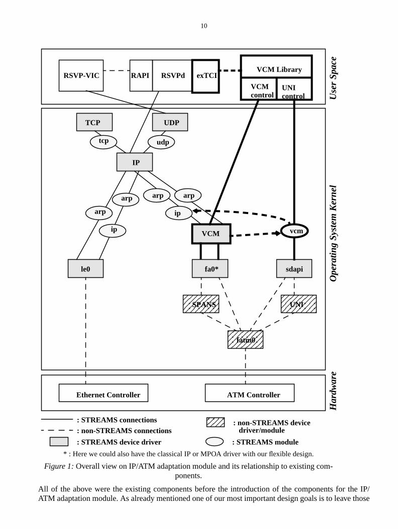
of the operating system and the ATM network driver. This is illustrated in Figure 1. Let us start frombottom up. Here we have the hardware of the network adaptors, i.e. the Ethernet† respectively the ATMcontroller. This corresponds to the physical layer. In the case of Ethernet the link layer is almostand is realized in a moderately sized character device driver called le0 (under Solaris) on top ofthe higher layer protocols are stacked. In a System V UNIX (as Solaris is one) the link layer wouldvide a standard interface called DLPI in order to offer its services to the network layer (in the caBSD-based systems the ifnet interface would be provided by the link layer module). Furthermoredepicted in Figure 1, the upper layer protocol stack in System V UNIXes, i.e. the network and tranlayer is implemented in kernel space using the STREAMS framework. The IP STREAMS multipdriver serves as the central component receiving several streams from upstream and multiplexinon the correct downstream directions to the corresponding network drivers (according to the roforwarding table). From the IP multiplexer there are always two streams leading downstream to thwork device drivers where one is for the ARP control requests and the other is for the actual datato be sent over the network. For the former stream the ARP module is pushed, while for the latterand the ARP module are pushed, in that order. Upstream from the IP multiplexer there are the tralayer STREAMS device drivers, the most common of which certainly are the TCP and UDP drThere is one stream for each transport layer. On such a stream a module corresponding to the retransport layer is being pushed as can be seen again in Figure 1. Applications that want to seusing the TCP/IP protocol suite are of course run in user space and transmit their data to the tralayer devices by opening up a stream to the transport layer STREAMS devices (it is also possbuild up a stream directly to the IP multiplexer using "raw" IP, as for example does the RSVP daemsend its protocol messages) and crossing the user-kernel borderline by using the STREAMS heexample of such an application depicted in Figure 1 is the conferencing tool vic, of which there iscial release that is RSVP-enabled, i.e. uses RSVP signalling in order to reserve resources for itflows to experience uncongested transmission paths. This is achieved by contacting the RSVP dthat is running in user space via an API called RAPI (which is under standardization by the X/Ogroup).
Let us now take a look on the ATM-side of our edge device. The ATM network driver is considermore complex than the Ethernet network driver and is itself constructed of several modules thatwork with each other. Some of them, but not all, are depicted in Figure 1. The lowest, respectivelyest to the hardware controller is a character device driver named fatm0 which interfaces directlyhardware of the ATM network adaptor and makes available some very basic functionality like seand receiving data, reserving local VC resources, etc. Eventually, all the other functionality as e.nalling is based on those functions in the fatm0 driver. The Fore code encompasses two differentling modules (implemented as character device drivers):
• Fore’s proprietary SPANS signalling protocol, and• the standard-conform UNI 3.0/3.1 signalling as specified by the ATM Forum.
On top of the signalling modules and the basic fatm0 module there are several modules for dikind of purposes, still implemented in kernel space. In Figure 1, two of them are depicted:
• the Fore IP device STREAMS driver (called fa0), implementing Fore’s proprietary convergmodule for realizing best-effort IP transmissions over an ATM subnet by using facilities providethe SPANS signalling,
• the SDAPI device STREAMS driver (called sdapi), implementing a signal-driven API that allowdirect access to the facilities provided by the UNI signalling.
†. We assumed the IP-side of the edge device to be connected to an Ethernet as it was actuallycase in our test settings.
10
e IP/those
All of the above were the existing components before the introduction of the components for thATM adaptation module. As already mentioned one of our most important design goals is to leave
arp
ip
arp
IP
TCP UDP
udptcp
arp
ip
arp
VCM
le0
RSVPd exTCIVCM Library
VCMcontrol
UNIcontrol
vcm
sdapi
UNISPANS
fatm0
Ethernet Controller ATM Controller
fa0*
Ope
ratin
g S
yste
m K
erne
lU
ser
Spa
ceH
ardw
are
RAPIRSVP-VIC
: STREAMS connections: non-STREAMS connections
: STREAMS device driver
: non-STREAMS device
: STREAMS module
driver/module
* : Here we could also have the classical IP or MPOA driver with our flexible design.
Figure 1:Overall view on IP/ATM adaptation module and its relationship to existing com-ponents.
11
. Thewithted
he taskATM
catinge IPulti-
tion ofy
h haspassedexerbeen
beingwhatse hasto thedottedding
in theentedns areof thefigu-
emonS98].tion
to setnsistertain,there
teps todge
e predi-by log-nts a
ormal
components untouched in order to be able to distribute code of our IP/ATM adaptation modulecomponents realizing the functionality of our IP/ATM adaptation module are depicted in Figure 1bold frames. The most important is the VCM STREAMS device multiplexing driver which is locabetween the IP multiplexer and a convergence IP module (in the example Fore IP was taken). Tof the VCM device is to multiplex the IP data streams according to configurable parameters ontoVCs. The IP multiplexer essentially does not see the Fore IP driver any more but is now communidirectly to the VCM multiplexer which however provides the same interface (DLPI) as the Fordevice driver so that the IP multiplexer does not realize it "talks" to someone else. The VCM mplexer examines the IP datagram against a set of filters that are configured into it. The configurathe filters is possible via anioctl interface of the VCM multiplexer (more details in chapter 3). If anof the filter rules applies, the VCM multiplexer routes the datagram onto the respective VC whicbeen setup beforehand (see below on how), if none of the filters apply then the datagram is juston to the fa0 driver. For the "rerouting" of the data over especially setup VCs, the VCM multiplhands the successfully matched datagrams over to the VCM STREAMS module, which haspushed on the SDAPI STREAMS device. In the VCM module the IP datagrams are prepared forsent over their ATM VC by prepending an internal header required for the SDAPI driver. That ishas to be done for the ingress to an ATM network. For the egress from the ATM network, the inverto be done by the VCM module: stripping off the internal header and putting the IP datagram inupward directed stream to the IP multiplexer. These actions are depicted in Figure 1 by thearrows from the VCM device to the VCM module and from the VCM module to the data stream leainto the IP multiplexer.
The remaining question certainly is: who sets up the VCs and controls the filter configurationVCM device. This is done in user space by an instance of the VCM module that is being implemas a library. This library uses the SDAPI provided by Fore to setup and manage VCs. These actiorecorded by the VCM module and thus it is able to construct the required internal headers for useespecially set up VCs. The other task of controlling the VCM device by managing its filter set conrations is also done by the VCM user library. The VCM library is all a user as e.g. the RSVP dasees when implementing its extended Traffic Control Interface (exTCI) as described in [SKWTherefore the VCM library interface is a crucial part of the overall design of the IP/ATM adaptamodule and we take closer look at it in the next section (for details see chapter 4).
2.4 Interface to the IP/ATM Adaptation Module
The interface to the IP/ATM adaptation module is implemented as a user level library that allowsfilters into the forwarding path from the IP-side of an edge device to the ATM-side. Here, filters coof a number of rules which map data flows on a number ATM VCs that can each be setup with a cspecified QoS. The user of that library only needs to supply the logic for which data streams/flowsshould be special treatment by the ATM subnetwork, the VCM module takes all the necessary ssetup corresponding VCs by using UNI signalling, rerouting the data path within the IP/ATM edevices, and so on as described above. The logic is a simple restricted predicate logic, where thcates are based on arbitrary conditions in the headers including and above the IP layer combinedical ANDs, thus constituting a filter rule, while an ORed concatenation of such filter rules represefilter which is mapped on a set of VCs, where the sets of the VC endpoints is disjunct. In a more fway filters can be described as:
Let Ai,j(p), i=1,...,n, j=1,...,k, be predicates defined on the contents of the IP packet p,
e.g. Ai j, p( ) 1 if IP dest-addr = a.b.c.d
0 otherwise
=
12
indsons ares fieldss to beg for-
evernext
ctions
simpletched.ctures
lwaysthat the
ossi-ard: order
plumb-
-basedters)to thetic of
es that
ystem
version
(at there is
able
then constitutes a filter rule forj=1,..,k,
and constitutes a filter (withendpoints(VCi) ∩ endpoints(VCj)
= {} for all i,j).
Since flexibility was the most important design goal for the interface towards the VCM, different kof matching actual packet header subfields against filters where introduced, i.e. predicate definitivery general. For example it is possible to do mask matches which is particularly suited to addresthat are structured as e.g. IP’s source and destination address fields, thus allowing for filter ruledefined on whole IP subnets (e.g. "all traffic from subnet a.b.c shall take extra VC v when beinwarded to subnet d.e.f").
2.5 Functional Restrictions of the Current Implementation
In this subsection we want to outline restrictions of the current implementation, which should hownot be critical for the use of the VCM module as a prototype and which will be overcome in thereleases of the IP/ATM adaptation module in the next phase of the IQATM project. These restriare:
• Ease of implementation was often given preference over efficiency, as e.g. in the case of thelist of the filters inside the kernel module against which any incoming packets has to be maHere certainly is much room for improvement by using a more sophisticated, tuned data struwhich allows for faster matching against the filter rules.
• The adaptation module is certainly very system-specific, however code at this level probably ais. Nevertheless, we made a serious try to isolate system-specific code from general code soporting task is simplified.
• At the moment only one user of the IP/ATM adaptation module per ATM network interface is pble at a time. However introducing multi-user capabilities into the library should be straightforw• In the kernel module some additional identification for different users needs to be added in
to restrict users administrative operations on filters onto their set of filters.• In the user level instance/library it must be ensured that some actions, e.g. the set up of the
ing are only executed once for all users and not once for each user.
• Furthermore, there maybe problems with filters that can apply at the same time, here a prioritymechanism (set by policies: e.g. IntServ-related filters may be of higher priority than DiffServ filshould be devised. Again this should be very easy to achieve by simply adding a priority fieldfilter structure in the kernel and just propagating the configuration of that additional characterisa filter through the user library to the actual users of the adaptation module, which are the onhave the knowledge to set such policies/priorities.
2.6 System Requirements
Having mentioned that the code is system-specific, we certainly have to specify which are the srequirements when actually running the code as it is provided:
• The edge devices must be running under the SUN Solaris 2.5.1/2.6 operating system (earlierof Solaris should be no problem, but were not tested).
• The edge devices must use Fore network adapters with ForeThought’s Software Release 5.0time of writing it is unfortunately not yet absolutely clear whether a source code license from Forequired in order to access the SDAPI library interface).
• The previous point means we are using ATM’s UNI 3.0/3.1 to signal VCs, thus a switch must beto understand this signalling.
F j A1 p( ) … An p( )∧ ∧=
F F1 … Fk∨ ∨ VC1 … VCv, ,;( )=
13
t sureurers,evicesed as
• During our development and testing we only used a Fore switch (Fore LE 155). We are nowhether signalling would work if edge devices are connected to switches of other manufactwhich in theory they certainly should. Therefore we recommend a test scenario where edge dare connected to Fore switches while inside the ATM network other ATM switches could be uswell.
14
out inernelayering
ect
hortsys-ystem.de inmakes
asonedmore
ernelg mod-f the
al andion ofpre-neral
nicateetails
calls tokernel.
e readsizedaracterriver.d net-ffer an
3 The VCM Kernel Instance
3.1 Overview
In this section the kernel part of the VCM module is presented in more detail. As already pointedthe last section, one of the main goals for the design of the VCM module is to keep the VCM kinstance as minimal and lean as possible and to extend its services by the user level module (lprinciple). The reasons for that are:
• ease of development,• comfort of programming,• maximum use of existing facilities of the ATM network driver code (a user-level API allowing dir
access to the UNI signalling is available).
In order to explain in more detail the inner working of the VCM kernel instance, we first give a sreview of UNIX device drivers in general and the STREAMS mechanism found in System V Unixtems, as e.g. SUN’s Solaris, in order to implement (among other things) the communication subsFurthermore, we present a high level overview of the architecture of Fore’s ATM network driver coorder to be able to show how the VCM kernel instance interfaces to that code, respectively how ituse of the facilities provided by the driver.
Although the design goals for the IP/ATM adaptation module have already been stated and reabout in the discussion on the overall architecture of the VCM module, we again look at these in aconcrete and detailed fashion for the VCM kernel instance. Next, the architecture of the VCM kinstance is being regarded with an emphasis on how the VCM kernel instance is related to existinules which are either part of the operating system or part of the ATM network driver. In the rest osection we then delve into the details of the implementation of the VCM kernel instance.
3.2 Review of UNIX Device Drivers and the STREAMS Mechanism
In this subsection we review the fundamental concepts of System V Unix device drivers in generthe STREAMS framework in order to ease understanding of the description of our implementatthe IP/ATM adaptation module. Of course, this is only a very shallow overview and without anyknowledge it might be difficult to follow later on, so for a more complete presentation of these geissues we refer to ([Sun96], [Sun95].
3.2.1 UNIX Device Drivers
A device driver consists of a set of routines that allows the kernel and user programs to commuwith peripheral devices. The purpose of a device driver is to hide the complex device-specific dfrom the user and the rest of the operating system. It allows the user to use regular file systemaccess a device by translating them into device specific commands. Device drivers are part of theThere are two basic categories:
• block device drivers, and• character device drivers.
Block device drivers are used for peripherals which must handle file systems, like hard disks. Thand write operations use fixed size data blocks. Character device drivers do not require fixedblocks for the read and write operation. Therefore, almost every device can be accessed via a chdevice driver. Even classical block devices can be handled by a special "raw" character device d
Character device drivers are typically used for asynchronous terminals (serial drivers), mice anwork adapter cards. A special type of character device drivers are pseudo device drivers. They o
15
"/dev/ernelfollowevice
thepares thee. Thea user
whenhe cur-
t is toit hashe ker-eachformvicesvers do
vide apendss con-ndler
m thatniente inde-
ts of ad onto
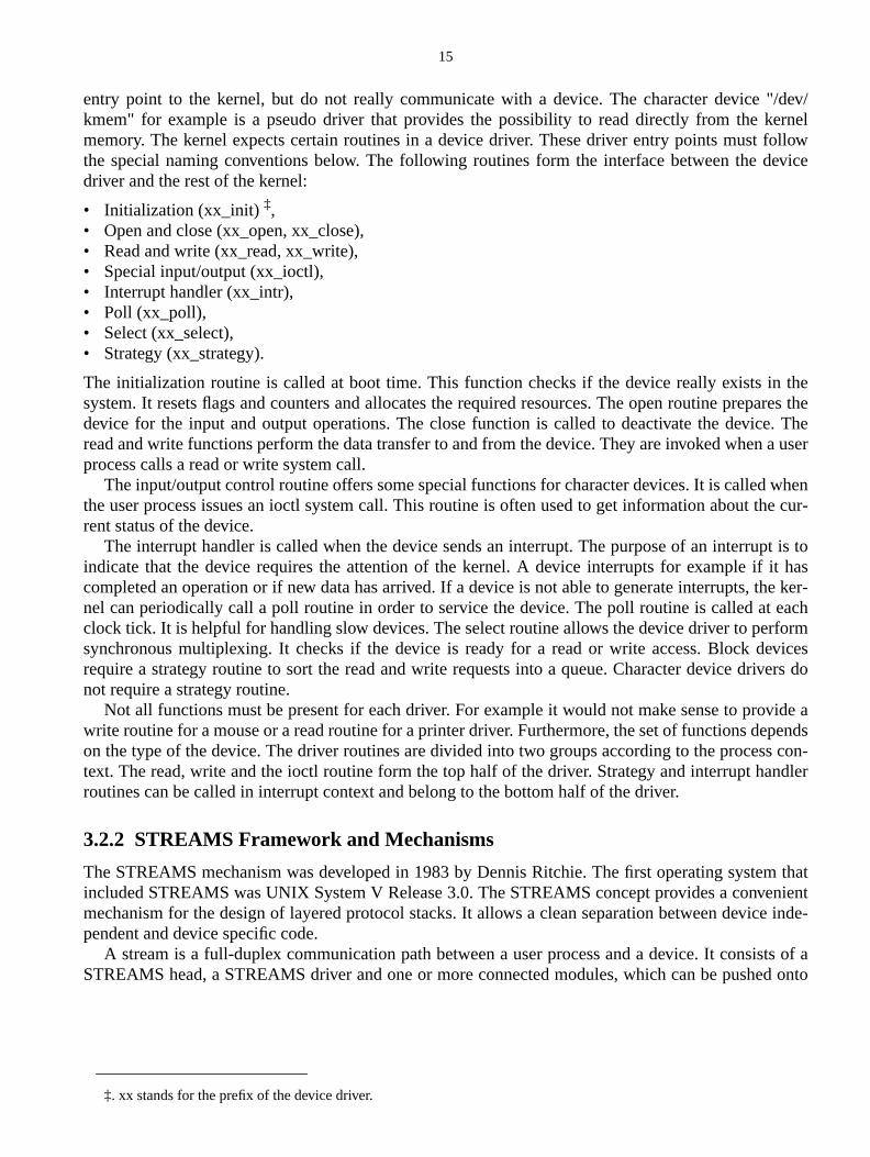
entry point to the kernel, but do not really communicate with a device. The character devicekmem" for example is a pseudo driver that provides the possibility to read directly from the kmemory. The kernel expects certain routines in a device driver. These driver entry points mustthe special naming conventions below. The following routines form the interface between the ddriver and the rest of the kernel:
• Initialization (xx_init)‡,• Open and close (xx_open, xx_close),• Read and write (xx_read, xx_write),• Special input/output (xx_ioctl),• Interrupt handler (xx_intr),• Poll (xx_poll),• Select (xx_select),• Strategy (xx_strategy).
The initialization routine is called at boot time. This function checks if the device really exists insystem. It resets flags and counters and allocates the required resources. The open routine predevice for the input and output operations. The close function is called to deactivate the devicread and write functions perform the data transfer to and from the device. They are invoked whenprocess calls a read or write system call.
The input/output control routine offers some special functions for character devices. It is calledthe user process issues an ioctl system call. This routine is often used to get information about trent status of the device.
The interrupt handler is called when the device sends an interrupt. The purpose of an interrupindicate that the device requires the attention of the kernel. A device interrupts for example ifcompleted an operation or if new data has arrived. If a device is not able to generate interrupts, tnel can periodically call a poll routine in order to service the device. The poll routine is called atclock tick. It is helpful for handling slow devices. The select routine allows the device driver to persynchronous multiplexing. It checks if the device is ready for a read or write access. Block derequire a strategy routine to sort the read and write requests into a queue. Character device drinot require a strategy routine.
Not all functions must be present for each driver. For example it would not make sense to prowrite routine for a mouse or a read routine for a printer driver. Furthermore, the set of functions deon the type of the device. The driver routines are divided into two groups according to the procestext. The read, write and the ioctl routine form the top half of the driver. Strategy and interrupt haroutines can be called in interrupt context and belong to the bottom half of the driver.
3.2.2 STREAMS Framework and Mechanisms
The STREAMS mechanism was developed in 1983 by Dennis Ritchie. The first operating systeincluded STREAMS was UNIX System V Release 3.0. The STREAMS concept provides a convemechanism for the design of layered protocol stacks. It allows a clean separation between devicpendent and device specific code.
A stream is a full-duplex communication path between a user process and a device. It consisSTREAMS head, a STREAMS driver and one or more connected modules, which can be pushe
‡. xx stands for the prefix of the device driver.
16
makes
driver isdicate its
containd data.on istine is
m. Theyf a pairts of ae a ser-
. Thellocated
userpstream
arac-r pro-Like the
donef theeralhichThishichcom-
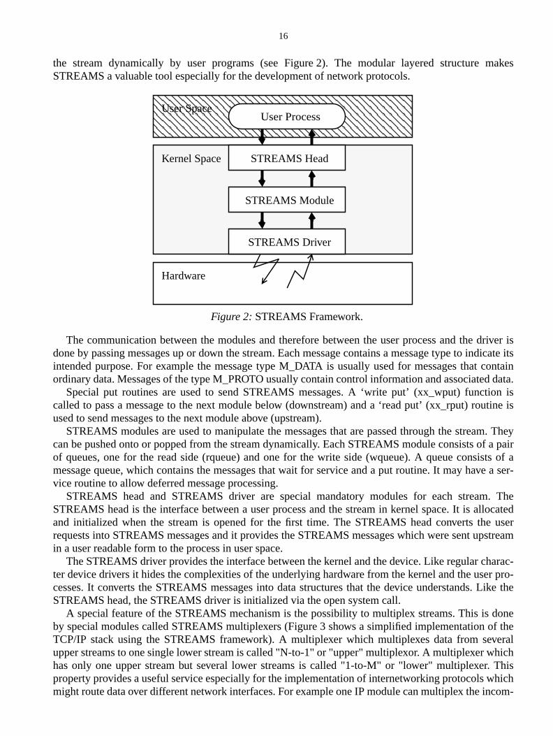
the stream dynamically by user programs (see Figure 2). The modular layered structureSTREAMS a valuable tool especially for the development of network protocols.
The communication between the modules and therefore between the user process and thedone by passing messages up or down the stream. Each message contains a message type to inintended purpose. For example the message type M_DATA is usually used for messages thatordinary data. Messages of the type M_PROTO usually contain control information and associate
Special put routines are used to send STREAMS messages. A ‘write put’ (xx_wput) functicalled to pass a message to the next module below (downstream) and a ‘read put’ (xx_rput) rouused to send messages to the next module above (upstream).
STREAMS modules are used to manipulate the messages that are passed through the streacan be pushed onto or popped from the stream dynamically. Each STREAMS module consists oof queues, one for the read side (rqueue) and one for the write side (wqueue). A queue consismessage queue, which contains the messages that wait for service and a put routine. It may havvice routine to allow deferred message processing.
STREAMS head and STREAMS driver are special mandatory modules for each streamSTREAMS head is the interface between a user process and the stream in kernel space. It is aand initialized when the stream is opened for the first time. The STREAMS head converts therequests into STREAMS messages and it provides the STREAMS messages which were sent uin a user readable form to the process in user space.
The STREAMS driver provides the interface between the kernel and the device. Like regular chter device drivers it hides the complexities of the underlying hardware from the kernel and the usecesses. It converts the STREAMS messages into data structures that the device understands.STREAMS head, the STREAMS driver is initialized via the open system call.
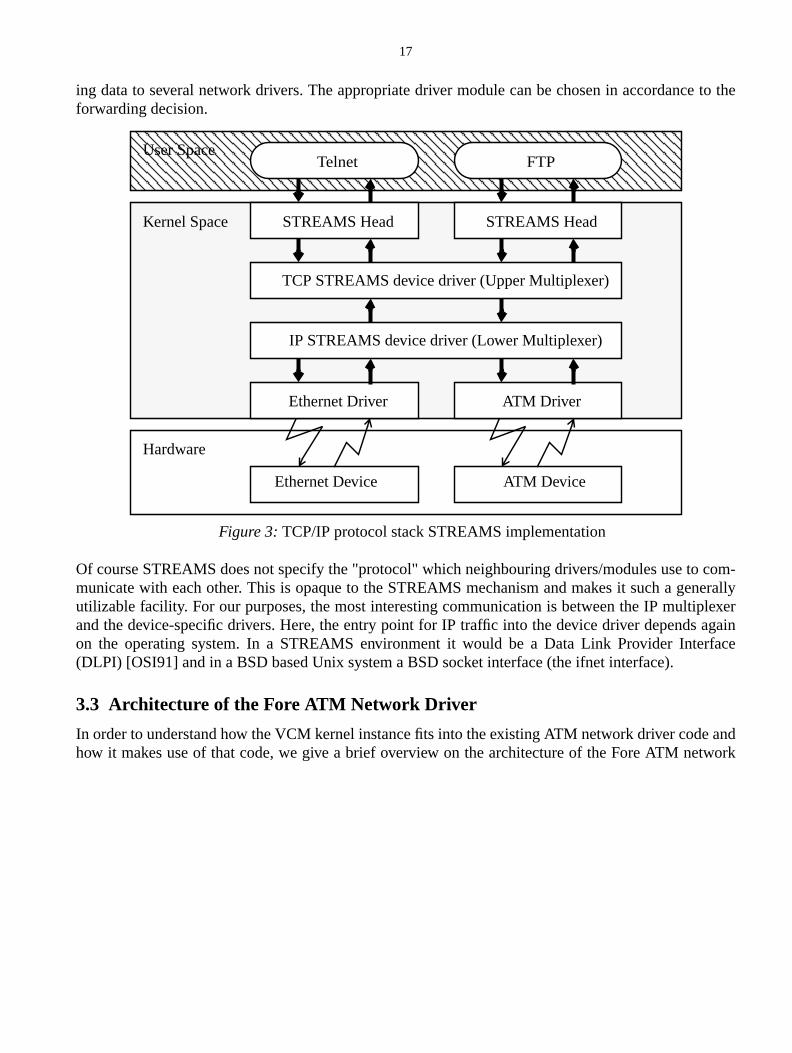
A special feature of the STREAMS mechanism is the possibility to multiplex streams. This isby special modules called STREAMS multiplexers (Figure 3 shows a simplified implementation oTCP/IP stack using the STREAMS framework). A multiplexer which multiplexes data from sevupper streams to one single lower stream is called "N-to-1" or "upper" multiplexor. A multiplexer whas only one upper stream but several lower streams is called "1-to-M" or "lower" multiplexer.property provides a useful service especially for the implementation of internetworking protocols wmight route data over different network interfaces. For example one IP module can multiplex the in
Hardware
User Space
Kernel Space STREAMS Head
STREAMS Module
User Process
Figure 2:STREAMS Framework.
STREAMS Driver
17
to the
com-nerallylexeragainrface
andwork
ing data to several network drivers. The appropriate driver module can be chosen in accordanceforwarding decision.
Of course STREAMS does not specify the "protocol" which neighbouring drivers/modules use tomunicate with each other. This is opaque to the STREAMS mechanism and makes it such a geutilizable facility. For our purposes, the most interesting communication is between the IP multipand the device-specific drivers. Here, the entry point for IP traffic into the device driver dependson the operating system. In a STREAMS environment it would be a Data Link Provider Inte(DLPI) [OSI91] and in a BSD based Unix system a BSD socket interface (the ifnet interface).
3.3 Architecture of the Fore ATM Network Driver
In order to understand how the VCM kernel instance fits into the existing ATM network driver codehow it makes use of that code, we give a brief overview on the architecture of the Fore ATM net
Hardware
User Space
Kernel Space STREAMS Head
FTP
Figure 3:TCP/IP protocol stack STREAMS implementation
ATM Driver
STREAMS Head
TCP STREAMS device driver (Upper Multiplexer)
Telnet
Ethernet Driver
Ethernet Device ATM Device
IP STREAMS device driver (Lower Multiplexer)
18
ted in
gence-inde-g data
terde-les use
ndter-
illing-is thell asThose
o the
nd
ming
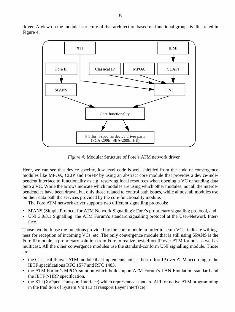
driver. A view on the modular structure of that architecture based on functional groups is illustraFigure 4.
Here, we can see that device-specific, low-level code is well shielded from the code of convermodules like MPOA, CLIP and ForeIP by using an abstract core module that provides a devicependent interface to functionality as e.g. reserving local resources when opening a VC or sendinonto a VC. While the arrows indicate which modules are using which other modules, not all the inpendencies have been drawn, but only those related to control path issues, while almost all moduon their data path the services provided by the core functionality module.
The Fore ATM network driver supports two different signalling protocols:
• SPANS (Simple Protocol for ATM Network Signalling): Fore’s proprietary signalling protocol, a• UNI 3.0/3.1 Signalling: the ATM Forum’s standard signalling protocol at the User-Network In
face.
Those two both use the functions provided by the core module in order to setup VCs, indicate wness for reception of incoming VCs, etc. The only convergence module that is still using SPANSFore IP module, a proprietary solution from Fore to realize best-effort IP over ATM for uni- as wemulticast. All the other convergence modules use the standard-conform UNI signalling module.are:
• the Classical IP over ATM module that implements unicast best-effort IP over ATM according tIETF specifications RFC 1577 and RFC 1483.
• the ATM Forum’s MPOA solution which builds upon ATM Forum’s LAN Emulation standard athe IETF NHRP specification.
• the XTI (X/Open Transport Interface) which represents a standard API for native ATM programin the tradition of System V’s TLI (Transport Layer Interface).
Platform-specific device driver parts(PCA-200E, SBA-200E, HE)
UNISPANS
SDAPI
ILMI
Fore IP Classical IP
XTI
MPOA
Core functionality
Figure 4:Modular Structure of Fore’s ATM network driver.
19
ectly
thele issh its
everevenMS
essage
nce,
higherimple-
e-ld bes ofhouldtocol,elds).
s whichonfig-tance
by thed that. C++.
• the SDAPI which is the kernel-level component for a user-level library that allows to access dirthe UNI 3.0/3.1 signalling services.
Another module is ILMI (Interim Local Managment Interface), which helps in autoconfiguringATM network by e.g. soliciting ATM addresses of a certain network interface, etc. The ILMI moduimplemented on top of the SDAPI module, i.e. uses its interface to the UNI signalling to accomplitask.
Internally, the ATM driver modules are not implemented as STREAMS modules/drivers. Howall the modules that interface to upper layers of the protocol stack (CLIP, Fore IP, MPOA) ordirectly to the user (XTI, SDAPI) provide a STREAMS interface, i.e. are ready to receive STREAmessages. In the case of the IP convergence modules (CLIP, Fore IP, MPOA) the STREAMS mpassing is based on the DLPI.
3.4 Design Goals and Decisions
Apart from the design goals for the overall architecture which also apply to the VCM kernel instathere are also more specific design goals for the VCM kernel instance:
• The functionality provided by the VCM kernel instance should be keptminimal , but complete("Keep it lean and clean"). The goal was to designatomic functions which can be composed to anenhanced higher level service provided by the VCM user instance. The rationale for this is theeffort required for development and coding in the kernel space when compared to user spacementations.
• Despite minimality the VCM kernel instance should offer as muchflexibility as possible, especiallywith regard to thespecificationof rules that specify which packets belong to a flow for which spcial VCs are available (virtually any information contained in IP and upper layer headers shoupossible to qualify for such special treatment by the ATM network). In particular different kindgranularity should be possible, e.g. traffic from certain subnets (identified by CIDR prefixes) sbe a possible criterion as well as application subflows that are qualified by e.g. (transport prosource address, destination address, source port, destination port, and/or even RTP header fi
• The STREAMS-related operations should be separated as far as possible from the operationare needed to accomplish the required functionality of routing the IP packets according to curable criteria on different especially setup VCs. Hence, the structure of the VCM user insshould bemodular.
A design decision we made was to implement the VCM kernel instance in C. This was motivatedfact that the STREAMS framework and the kernel entry points are to be specified in C anyway anit would make only limited sense to have a hybrid design by introducing another language, as e.gFurthermore, performance is an argument for using C.
20
rnel
IPr theuserthe IP
multi-lexesis theagram
to anyd IP
3.5 Architecture of the VCM Kernel Instance
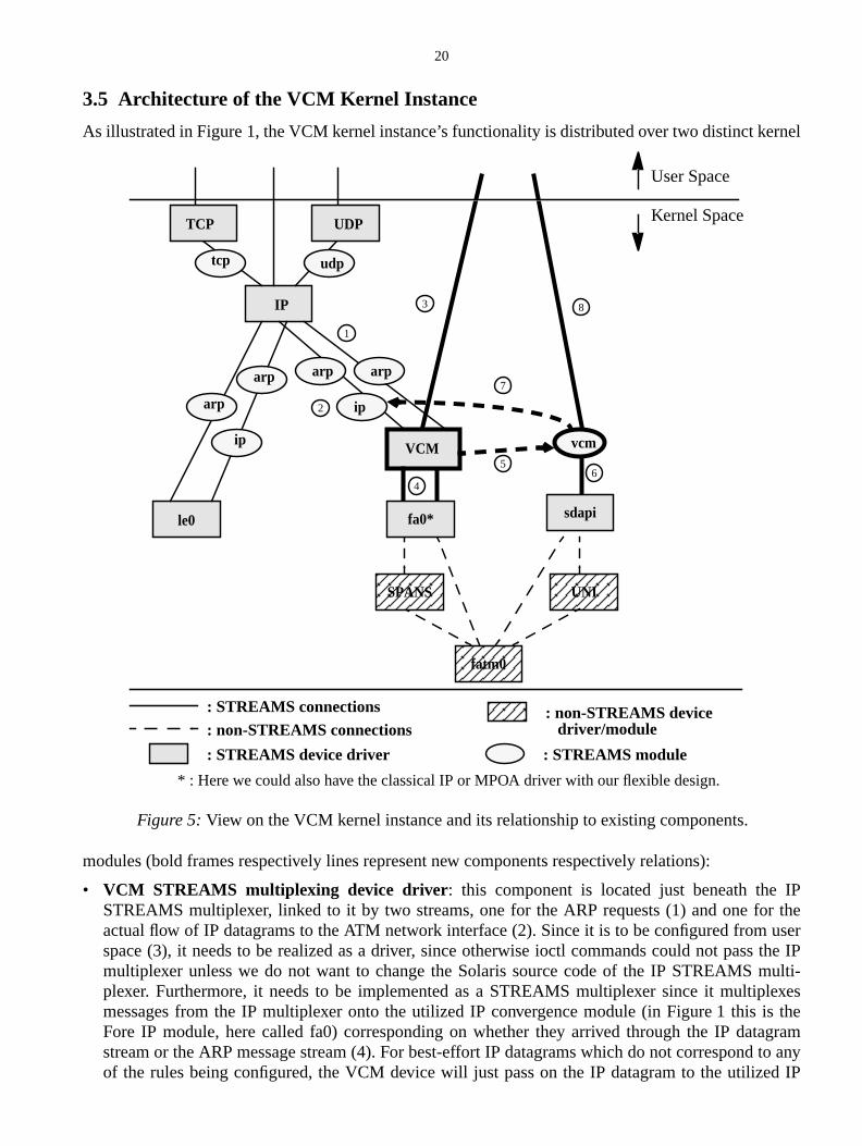
As illustrated in Figure 1, the VCM kernel instance’s functionality is distributed over two distinct ke
modules (bold frames respectively lines represent new components respectively relations):
• VCM STREAMS multiplexing device driver : this component is located just beneath theSTREAMS multiplexer, linked to it by two streams, one for the ARP requests (1) and one foactual flow of IP datagrams to the ATM network interface (2). Since it is to be configured fromspace (3), it needs to be realized as a driver, since otherwise ioctl commands could not passmultiplexer unless we do not want to change the Solaris source code of the IP STREAMSplexer. Furthermore, it needs to be implemented as a STREAMS multiplexer since it multipmessages from the IP multiplexer onto the utilized IP convergence module (in Figure 1 thisFore IP module, here called fa0) corresponding on whether they arrived through the IP datstream or the ARP message stream (4). For best-effort IP datagrams which do not correspondof the rules being configured, the VCM device will just pass on the IP datagram to the utilize
arp
ip
arp
IP
udptcp
arp
ip
arp
VCM
le0
UNI
fatm0
fa0* sdapi
vcm
User Space
Kernel Space
: STREAMS connections: non-STREAMS connections
: STREAMS device driver
: non-STREAMS device
: STREAMS module
driver/module
* : Here we could also have the classical IP or MPOA driver with our flexible design.
Figure 5:View on the VCM kernel instance and its relationship to existing components.
TCP UDP
1
3
2
4
8
6
SPANS
7
5
21
e IPicesssages. How-e, thatother
" theations
amAPI
) andof the
ciallyto the
m theal buff-rule to
more:ulti-s. If itout ofmod-d thescrip-en the
to the
m toond-filterVCM
ally be
take.
eral ar andcode
convergence module. Similarly, for all the configuration when the plumbing between thSTREAMS device and the ATM network interface is set up, the VCM device utilizes the servprovided by the IP convergence module and again just passes the related STREAMS meexchanged between the IP device driver and the IP convergence module driver back and forthever, if an IP datagram passes by that satisfies any of the rules configured into the VCM devicIP datagram will be taken out of the default best-effort data path and be handed over to thecomponent of the VCM kernel instance: the VCM STREAMS module. Note that by "squeezingVCM device between the IP multiplexer and the IP convergence module there are no modificnecessary, neither for the Solaris operating source code nor for the ATM network driver code.
• VCM STREAMS module: this component "sits" on top of the SDAPI device driver on the strefrom the VCM user instance, which manages the VCs by using the SDAPI library, to the SDdevice. The main task of the VCM module is to receive IP datagrams from the VCM device (5passing them on to the SDAPI device (6), thus representing an entry point into the queuesSDAPI device for the different VCs. In the reverse direction, for data arriving on those espesetup VCs the VCM module again acts as an entry point of the received IP datagrams back inIP device driver’s queues (7). Furthermore, the VCM module listens to all SETUP requests froVCM user instance (8) and copies the negotiated headers for sending on those VCs into interners that can later on be associated to filter rules thus allowing IP datagrams satisfying the filterbe actually sent on that VC.
It is crucial to understand how these two component work together, so let it be emphasized oncethe VCM STREAMS multiplexing driver examines the flow of IP datagrams passed from the IP mplexer to the ATM network interface represented by any of the possible IP convergence moduledetects an IP datagram that matches any of the filter rules in its filter set, this datagram is takenthe default path to the respective IP convergence module and handed over to the VCM STREAMSule which passes it on to the SDAPI STREAMS device driver. To enable the SDAPI device to sendatagram on the associated VC of the matching filter rule, an internal header indicating the VC detor and other information needs to be prepended. This header is recorded by the VCM module whVC is set up by the VCM user instance, which is possible since the VCM module is pushed onstream between the VCM user instance and the SDAPI device driver.
The configuration of the filter set is being done by the VCM user instance via a controlling streathe VCM device driver (3) using ioctl system calls with various VCM-specific commands corresping to actions as e.g. introduction of a new filter, deletion of an existing filter, etc. Whenever a newis set up by issuing the corresponding ioctl, the SDAPI-specific headers being recorded by themodule for the last SETUP requests are associated with that filter (note that those can potentimultiple).
3.6 Modules of the VCM Kernel Instance
After having introduced the fundamental global architecture of the VCM kernel instance let us nowa more local and detailed view on the internal modules that implement the VCM kernel instance
3.6.1 Solaris Device Driver Specifics Module:vcm_ddi.c
This module implements all the necessary functions for a Solaris device driver, respectively in genSolaris loadable kernel module. This code is partially shared between the VCM STREAMS drivethe VCM STREAMS module and partially specific for each of those two. It is very system-specificthat is why it was isolated in a separate module.
22
rnellaris-.ernelten ins fortraight-
ode ofms toetersowinglwaysocedure
f theddi-ing
rmal
it hasuser
n()’s ite, in thatsys-
ses ofevice
is thefor allevice iseiveAMS
in the
at wereise the
The shared functionality for the VCM STREAMS device and module is with regard to the keentry points for loadable kernel modules, which is the same for both. This code is extremely Sospecific and certainly needs a major porting effort when desiring to port the VCM kernel instance
The specific code for the device respectively the module is concerned with their different kentry points as e.g. for attaching, detaching, probing, etc. a device. All of these functions are writconformance to the DDI (Device Driver Interface) and DKI (Device Kernel Interface) specificationSystem V Unix systems, so that at least for those systems the porting of these parts should be sforward.
Since the Solaris operating system kernel is multi-threaded it is important to realize that the cthe VCM kernel instance needs to be MT-safe. The STREAMS framework offers some mechanisrestrict the parallelism among the different entry points for the STREAMS mechanisms: MT perim(for more details see [Sun95]). We have tried to allow as much parallelism as possible, yet not allfor race conditions inside our VCM kernel instance. Therefore we specified an inner perimeter aspanning a pair of queues and an outer perimeter with exclusive access to the open and close prof the VCM STREAMS driver and module.
3.6.2 VCM STREAMS Multiplexing Device Driver: vcm_dev.c
This module contains all the VCM STREAMS device specific functionality. This is composed ovarious STREAMS entry points typical for a STREAMS multiplexing device driver and some ational other functions mainly dealing with configuration of the VCM STREAMS device and handover the datagrams to the VCM STREAMS module.
3.6.2.1 Kernel Entry Points
The first entry point that is called when the VCM STREAMS device is opened (by using the nosystem call open()) is
int vcm_dev_open(queue_t *q, dev_t *devp, int flag, int sflag,cred_t *credp)
which does all the necessary initialization tasks. What this routine does depends upon how oftenbeen called already. When it is called the first time it assumes that the control queue from the VCMinstance is to be opened and makes the necessary initialization for that queue. For further opedetects that the control queue is already opened and opens as next queues the IP and ARP queuorder (which is the order in which the TCP/IP stack is built up (plumbed) in the Solaris operatingtem, which however could certainly be different for other operating systems or even other releaSolaris). Those two queues are initialized as well and further open()’s are rejected by the VCM dindicating that it is already busy, i.e. can service only one user instance at the same time.
To ensure that the order of the open()’s is correct is not part of the VCM STREAMS device buttask of the VCM user instance using the VCM device. When vcm_dev_open() has been calledthree queues then the upward STREAMS connections in Figure 1 have been set and the VCM dnow able to monitor the IP data stream from the IP multiplexer to the ATM network interface, recioctl commands from the VCM user instance and pass selected datagrams to the VCM STREmodule. Again it is under the responsibility of the VCM user instance to ensure that the plumbingdownward direction from the VCM device to the utilized IP convergence is set correct.
The logically inverse entry point is
int vcm_dev_close(queue_t*, int, cred_t*)
which just closes the queue that it was called for and releases some internal data structures thassociated with that queue. It is verified that the queue is one of control, ARP or IP queue, otherwclose is rejected.
23
angedVCM
the IPVCMcan be
erlreadymodulelity of
uled.
mecha-r queues
ossiblyon-ction
if anpassed
n to thervices
s on theframe-
Let us now come to the entry points that are really working on the data streams being exchbetween the IP multiplexer, the VCM device and the IP convergence module respectively theSTREAMS module. The first one is
int vcm_dev_uwput(queue_t *q, mblk_t *mp)
This function is always called when there are messages to be delivered downwards from eithermultiplexer or the VCM user instance. Let us start with the case of the control queue (from theuser instance to the VCM device). Here the main task is to receive different ioctl commands thatissued by the VCM user instance. Those ioctls can be:
• I_LINK : This will, when received the first time, link the VCM STREAMS multiplexer to the lowIP queue leading to the IP convergence module. When being called with the lower IP queue abeing setup it is assumed that now the lower ARP queue again leading to the IP convergenceis to be linked to the VCM device. Again, ensurance of the correct order is under the responsibithe VCM user instance.
• I_UNLINK : This will unlink the lower queues from the VCM device to the IP convergence modagain. The order of unlinking is the reverse order of the linking. Further unlinks will be rejecte
Success or failure of those ioctl commands is then passed back upstream using STREAMSnisms. It has to be noted that for the control queue, messages are never passed on to the loweinstead they are always terminated in the VCM device.
For the IP queue and the ARP queue, if a message from upstream is of a message type that pcontains data (M_DATA, M_PROTO or M_PCPROTO), it is examined more closely. If it actually ctains an IP datagram, then the actual data forwarding is delegated to the funvcm_dev_dataforwarding() which is described below.
Of course, the VCM device does the necessary flush handling for multiplexing driversM_FLUSH message is received. Any other messages for the IP and ARP queues are just beingon to the respective lower queues.
Unless they are not high priority messages all actions described above on passing messages olower queues are first queued in the queue serviced by the VCM device. The entry point that sethis queue is
int vcm_dev_uwsrv(queue_t *q)
This function just checks the upper queue on which an enqueued message arrived and then sendmessage to the respective lower queue subject to the flow control mechanism of the STREAMSwork.
The entry point for the service routine on the lower queue of the VCM STREAMS multiplexer is
int vcm_dev_lwsrv(queue_t *q)
• VCM_NEWFILTERVCM_ADDVC2FILTERVCM_CHANGEFILTERVCM_ADDFILTERVCM_CHANGEVC4FILTERVCM_DELFILTERVCM_DELETEVCFROMFILTER,VCM_EXISTFILTERVCM_LISTFILTERVCM_FLUSH
} These are ioctl commands that trigger functions thatdeal with the configuration and management of thefilter set maintained by the VCM STREAMS device.However that is delegated to the functionvcm_dev_user_ioctl() described below.
24
back-back-
vice.gence
dule toad putlexerernelP dat-LUSH
not high
corre-ork.
nabled
gered
uestsf thoselivered
fer ofcom-R,
_DATA,ata,
allinginghere is
This function is needed in order to ensure that, after the STREAMS flow control mechanism hasenabled a previously congested lower queue to the ATM network driver, the upper queue isenabled again. A lower put routine however is not necessary.
Those were all the entry points on the write side, let us now turn to the read side of the VCM deThe first routine that is invoked for messages coming from downstream (i.e. from the IP convermodule) is
int vcm_dev_lrput(queue_t *q, mblk_t *mp)
The main task of that function is to pass on the messages received from the IP convergence mothe corresponding upper queues, i.e. either to the IP or ARP queue. Another task of the lower reroutine is to record the replies of the IP convergence module to DLPI requests from the IP multipconcerning the length of the link layer header, which serve for optimizing the data path in the kimplementation. That knowledge is required for our purposes in order to be able to recognize all Iagrams and to be able to locate them in STREAMS messages. Furthermore, processing of M_Fmessages is provided.
Again as in the downstream case, messages are first queued in the VCM device unless they arepriority messages. The kernel entry point that services these enqueued messages is
int vcm_dev_lrsrv(queue_t *q)
This function checks for the lower queue on which the message was received and directs it to thesponding upper queue subject to the flow control mechanism enforced by the STREAMS framew
The kernel entry point
int vcm_dev_ursrv(queue_t *q)
is again just needed in order to ensure that after a previously congested IP multiplexer is back-eagain that this action is propagated to the lower queues as well.
3.6.2.2 Other Functions
Let us now turn to the other functions that are not kernel entry points, but which are however trigby the kernel entry point functions described above. The first of those functions is
int vcm_dev_user_ioctl(mblk_t *mp, struct iocblk *iocp)
Its task is mainly to direct the different ioctl commands to the functions actually handling those req(located in the module vcm_filter.c). Furthermore, the correct format and number of parameters orequests is checked and in case they are incorrect a corresponding error is triggered to be deupstream to the VCM user instance. Another task accomplished in this function is that the bufheaders recorded by the VCM STREAMS module is marked as already used if the respectivemands requires to do so (that is the case for the VCM_NEWFILTER, VCM_ADDVC2FILTEVCM_CHANGEVC4FILTER commands).
The function
int vcm_dev_dataforwarding(queue_t *q, mblk_t* mp)
is concerned with messages possibly containing IP datagrams. Those messages are of type MM_PROTO or M_PCPROTO. For M_DATA messages it immediately follows that they contain dwhile for the other two it must first be checked whether they really contain an IP datagram by cthe function check_for_data() . If an IP datagram is actually contained in the message bereceived than that datagram is being compared against the filter set in order to find out whether tan especially setup VC for delivery of that datagram. This filtering is done by calling the functionfil-
25
ge is
filter’snt, thenn passed
agram.
ule.func-entry
AMSaliza-shead-
DAPIdata forDAPI-rd thissure auilt upr typeI user
ntrol
ter() , which is part of the module vcm_filter.c. If that function signals success than the messarouted to the SDAPI device via the VCM STREAMS module using the function
int route2SDAPI(vcm_filter_t* f, mblk_t* mp)
This function prepends the stored headers for the identified filter to the message that matches therule. In case there are multiple headers, i.e. multiple VCs on which the IP datagram has to be sethe replication of the IP datagram takes place here. The messages constructed from this are theto the downstream queue of the VCM STREAMS module finally leading to the SDAPI device.
As already mentioned the function
int check_for_data(mblk_t* mp)
checks whether a given message of type M_PROTO or M_PCPROTO actually contains an IP dat
3.6.3 VCM STREAMS Module:vcm_mod.c
This module contains the functionality specific for the implementation of the VCM STREAMS modAgain we distinguish between the kernel entry points for the STREAMS mechanism and othertions, although the VCM module consists almost exclusively of the STREAMS-related kernelpoints.
3.6.3.1 Kernel Entry Points
The kernel entry point
int vcm_mod_open(queue_t *, dev_t *, int, int, cred_t *)
is called when the open() system call is issued for the SDAPI device (in case the VCM STREmodule is configured to be pushed on the SDAPI device). Besides the STREAMS-specific inititions this routine also sets the pointer (calledsdapi_q ) to its write queue such that the VCM device iable to pass filtered IP datagrams over to the VCM module. Furthermore the buffers for recordingers of recently setup VCs, the so-called VC template buffers, are initialized.
The inverse kernel entry point is
int vcm_mod_close(queue_t *)
being called when the SDAPI device is being close()’d. Thesdapi_q is invalidated and the VC tem-plate buffers are emptied.
The function
int vcm_mod_wput(queue_t *, mblk_t *)
monitors the stream from the VCM user instance (which uses the SDAPI user library) to the Sdevice for messages of type M_PROTO which then necessarily have to be messages containinga certain VC being setup before via the SDAPI user library. Such messages contain exactly the Sinternal format needed to send data onto VCs setup by the SDAPI device. We therefore recoheader in a VC template buffer and "swallow" the respective M_PROTO message. Again, to encorrect operation of that mechanism we need the VCM user instance to assert that per VC being bonly one time data is being sent from the VCM user instance onto that VC. Messages from othethan M_PROTO are just passed on (to not interfere with the communication between the SDAPlibrary and the SDAPI device) and are enqueued for service by the kernel entry point
int vcm_mod_wsrv(queue_t *)
which does not do much besides STREAMS-specific flush handling and enforcing the flow comechanism provided by the STREAMS framework.
26
to the type.
ader asage is
due toder the
SDAPI
withkernellist of
ecificchingmultiple
by thee fil-s.
f fil-r setDAPI-
The entry point for the upstream directed put routine
int vcm_mod_rput(queue_t *, mblk_t *)
is very simple and just enqueues STREAMS messages coming from the SDAPI device directedVCM user instance in the VCM module’s upstream queue unless they are not of the high priority
The such enqueued messages are then serviced by
int vcm_mod_rsrv(queue_t *)
which checks whether the messages are of type M_PROTO and have in their SDAPI-internal hetype field indicating that they are data messages. If that is the case then the respective messtripped off its SDAPI-internal header and passed on to the IP device directly, which is possiblethe fact that the lower IP upstream read queue was recorded when the VCM device was linked unIP multiplexer (during thevcm_dev_open() function).
3.6.3.2 Other Functions
The auxiliary function
void flush_VC_template_buffer()
purges the buffers containing the recently recorded headers for data that is to be sent to thedevice.
3.6.4 Filter Configuration and Management Module:vcm_filter.c
This module contains all the functionality related to filter-specific operations, which mainly dealsconfiguration and management of the filters, i.e. their rules and associated VCs. The VCMinstance maintains a set of all active filters. This set is currently implemented as a simple linkedthe following data structure
typedef struct vf {
predicate_list_t rule; /* Conjunction of packet predicates */
mblk_t** VC_template;
int no_VC_templates;
struct vf* next;
} vcm_filter_t;
Obviously, this is not efficient if the filter set becomes large. However, by separating the filter-spoperations from the rest of the code, it will be easy to optimize that data structure for fast matagainst IP datagrams passing by using the latest research results on packet classification undercriteria [SVSW98].
3.6.4.1 Filter Configuration and Management functions
The functions described here correspond directly to the ioctl commands that are recognizedupper write put routine of the VCM device. They can be further divided into actual operations on thter set and into diagnostic functions. Let us start with the former, supposedly more important one
The function
int vcm_newfilter(vcm_filter_t*)
inserts a new filter into the existing (possibly empty) filter set (at the beginning of the linked list oters). It first checks whether this is really a new filter or whether it is already contained in the filtethus ensuring that no duplicates are stored in the filter set. Furthermore, it associates the set of S
27
VCMdesired
ted bygiven
dded
tion, ther for
xistingy offilters.
ng VCVCM
sting
tem-which
cit theout
internal headers contained in the VC template buffer with the filter rule passed down from theuser instance. The VCM user instance further ensures that the VC template buffer contains thecontents for which VCs where set up by itself.
For the case that one or even several VCs shall be added to an existing filter, the function
int vcm_addvc2filter(vcm_filter_t*)
has been implemented. It copies the contents of the VC template buffer which has been populacorresponding operations in the VCM user instance, to the already existing VC templates of thefilter. Hence from now on, IP datagrams satisfying the filter’s rule will also be sent on the newly aVC(s).
The function
int vcm_changefilter(vcm_filterpair_t*)
allows to completely exchange the filter’s rule with the given filter’s rule without losing the associato the existing VCs on which data satisfying the filter’s rule are sent. The function is given bothexisting filter and the new filter rule. The existing filter rule is needed in order to locate the filtewhich the rule has to be exchanged.
The function
int vcm_addfilter(vcm_filterpair_t*)
adds a given filter to the existing filter set which however shares the same VC set as an already efilter, that is also given when it is being called. This allows for a disjunction of filter rules, i.e. if anthose filter rules is satisfied than a matched IP datagram is being sent on the shared VCs of those
If the VC set shall be exchanged while the filter rule is retained, then the function
int vcm_changevc4filter(vcm_filter_t*)
is needed. As usual it ensures again that the given filter exists and if it does it removes its existiset and copies instead the contents of the VC template buffer in place. Note again that it is theuser instance responsibility to populate the VC template buffer adequately.
The function
int vcm_delfilter(vcm_filter_t*)
deletes a given filter from the filter set. Of course it is first asserted that this filter is actually exiwithin the filter set.
If a VC is to be removed from a given filter, then the function
int vcm_deletevcfromfilter(vcm_deletevc_t*)
is appropriate. It is given the filter for which a VC is to be removed and the index of the VC whichplate shall be removed from the associated VC set of the filter. That index represents the order inthe VCs have been set up and must be tracked by the VCM user instance.
As already mentioned there also diagnostic functions that enable the VCM user instance to elistate of the VCM kernel instance with regard to the filter set. A simple, but useful function to findwhether a certain filter is actually existing in the VCM kernel instance’s filter set is
int vcm_existfilter(vcm_filter_t*)
If the filter exists it returnsFILTEREXISTS otherwise it returnFILTERDOESNOTEXIST.
The function
int vcm_flush()
28
n the
em) ofist of
func-
tes are
lready
r theis the
pecific
ee dif-
lue has
d value,
s to be
users ofs ofnition
allows to totally purge the filter set of the VCM kernel instance and should always be called wheVCM user instance finishes for whatever reason.
A further useful function is
int vcm_listfilter()
It dumps the filter set onto the console (and thus also in the log files of the Solaris operating systthe machine that is running the VCM module. An improved version of this could be to return that lfilters to the VCM user instance.
3.6.4.2 Other Functions
The above functions all corresponded directly to ioctl commands, now we describe some othertions of the vcm_filter.c module.
The first function is
vcm_filter_t* filter(mblk_t *mp, int offset)
which traverses the filter set and tries to match the given IP datagram (inmp at the offsetoffset )against one of the filters by calling the functionfilter_match() which is located in the modulevcm_rule.c (see below). If a matching filter is found the search can be stopped since no duplicaever inserted into the filter set.
The auxiliary function
vcm_filter_t* find_filter(vcm_filter_t*)
is used in all locations where it is necessary to locate a given filter either to ensure whether it aexists or because some configurational action is to be applied to it. It uses the functionrule_match()from the module vcm_rule.c (see below).
Another auxiliary function is
void kill_filter(vcm_filter_t*)
which frees all the heap-allocated memory for a given filter.
3.6.5 Filter Rule Matching Module:vcm_rule.c
This module contains all the functionality related to matching filter rules and the like. WheneveVCM shall be extended for new predicates defined on the contents of an IP datagram, then thisonly module that needs to be touched. That is the reason why it was separated from the filter-smodule vcm_filter.c.
As already described in Section 2.4, a rule is composed of conjuncted predicates. Currently thrferent kinds of predicates are supported:
• address-mask match predicates, which allow to specify a value and a mask and a matching vato be equal to the specified value at the positions defined by the mask,
• exact match predicates which require a matching value to be exactly the same as the specifieand
• range match predicates which allow to define a matching range in which the matching value halocated in order for the predicate to be true.
We assumed that with those three types of predicates most of the required semantics needed bythe VCM module should be covered, however if not, it is straightforward to introduce new kindpredicates. Everything that is needed, from the perspective of the VCM kernel instance, is the defi
29
edicate
y con-
eve.all beexist-
of an according data type and a matching function, as we have specified them for the three prtypes given above:
For the address-mask matching predicate we have the function
int address_match(address_predicate_t, ipaddr_t)
For the exact match predicate we have the function
int exact_match(exact_predicate_t, u_char)
For the range match predicate we have the function
int range_match(range_predicate_t, u_short)
Furthermore, there are functions needed that serve as interface to the filter-specific functionalittained in vcm_filter.c. One of them is the function
int rule_match(predicate_list_t, predicate_list_t)
that evaluates whether two given rules are the same or not and returns the result.
The function
int filter_match(vcm_filter_t *f, mblk_t *mp, int offset)
evaluates whether a given IP datagram (contained inmpat offsetoffset ) can be matched against thgiven filter by using the functionality provided by the predicate matching functions described abo
Note that the latter two functions also need some minor modifications if a new predicate type shintroduced respectively if filter rules shall be extended by new fields in an IP datagram even if theing predicates are used.
30
M usertance.oduleance.
of the
d fash-eafter,s to theetail
withcer-
e also
re we
is notis notrs arem the
d by
n fil-nkage
n. Theits ser-
rientedl inter-
4 The VCM User Instance
4.1 Overview
In this section the VCM user instance is being presented and discussed. The basic idea of the VCinstance is to add one more abstraction level above the services provided by the VCM kernel insThe rationale of this is to do as much as possible of the complex parts of the IP/ATM adaptation min user space, while only time-critical parts are done in kernel space by the VCM kernel instTherefore, the following tasks are done by the VCM user instance:
• signalling message handling,• enforcement of the rules necessary for the correct operation of the VCM kernel module,• extension/refinement of the capabilities/services of the VCM kernel instance - easier setting
filter rules,• address resolution,• optionally IP-ATM QoS mapping (not yet implemented).
Again we start by discussing the design goals specific to the VCM user instance in a more detaileion than possible when presenting the overall architecture of the IP/ATM adaptation module. Herwe present the architecture of the VCM user instance with an emphasis on how a user interfaceVCM library. In the following, we discuss the implementation of the VCM user instance in more din order to allow for possible modifications and extensions. At the end of the section we concludean illustrative example on how to actually use the VCM library in order to set up a special VC for atain flow of IP datagrams.
4.2 Design Goals and Decisions
Besides the overall design goals for the VCM module as a whole (as described in Section 2.2), whave had some more specific design goals for the VCM user instance. Those are:
• The interface to the VCM user instance should beflexible andeasyto use. It should beextensiblefor user code since not all potential uses of the VCM module can be anticipated now. Therefodecided to design it in anobject-oriented fashion.
• The VCM user instance shouldhide all the "knitty-gritty" details of the VCM kernel instance. Inprinciple, the VCM kernel instance already provides an interface to the user space. However, itvery convenient to use and many rules between using the VCM and the setup of VCs (whichpart of the VCM kernel instance) must be obeyed, as e.g. the fact that all actions to kernel filteapplied to the group of VCs that have been set up since the last action (ioctl) demanded froVCM kernel instance. Therefore one of the main tasks of the VCM user instance is toenforce therules implied by the overall design of distributing the functionality into user and kernel space anthe lean design of the VCM kernel instance. Furthermore, the VCM user instanceenrichesthe ser-vices provided by the VCM kernel instance by e.g. providing the disjunctive association betweeter rules applying to the same set of VCs (whereas the VCM kernel instance has no logical libetween such filters).
• Another important goal when developing the VCM user instance must be thedecent handling offailure conditions as e.g. the case where a switch breaks down and all the VCs are torn dowVCM user instance must be able to signal these asynchronous events to a potential user ofvices and must be able to indicate which VCs are actually affected.
With respect to the programming language we decided to use C++, since we wanted an object-ointerface design to be accompanied with object-oriented coding. However, since the system-leve
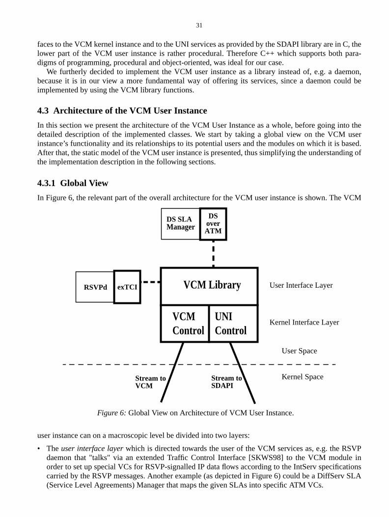
31
C, thepara-
mon,uld be
to theuserased.ing of
VCM
VPe inationsv SLA
faces to the VCM kernel instance and to the UNI services as provided by the SDAPI library are inlower part of the VCM user instance is rather procedural. Therefore C++ which supports bothdigms of programming, procedural and object-oriented, was ideal for our case.
We furtherly decided to implement the VCM user instance as a library instead of, e.g. a daebecause it is in our view a more fundamental way of offering its services, since a daemon coimplemented by using the VCM library functions.
4.3 Architecture of the VCM User Instance
In this section we present the architecture of the VCM User Instance as a whole, before going indetailed description of the implemented classes. We start by taking a global view on the VCMinstance’s functionality and its relationships to its potential users and the modules on which it is bAfter that, the static model of the VCM user instance is presented, thus simplifying the understandthe implementation description in the following sections.
4.3.1 Global View
In Figure 6, the relevant part of the overall architecture for the VCM user instance is shown. The
user instance can on a macroscopic level be divided into two layers:
• Theuser interface layerwhich is directed towards the user of the VCM services as, e.g. the RSdaemon that "talks" via an extended Traffic Control Interface [SKWS98] to the VCM modulorder to set up special VCs for RSVP-signalled IP data flows according to the IntServ specificcarried by the RSVP messages. Another example (as depicted in Figure 6) could be a DiffSer(Service Level Agreements) Manager that maps the given SLAs into specific ATM VCs.
RSVPd
User Space
Kernel Space
DS SLAManager
DSoverATM
Stream toSDAPI
Stream toVCM
exTCI
Kernel Interface Layer
User Interface Layer
Figure 6:Global View on Architecture of VCM User Instance.
VCM Library
VCMControl
UNIControl
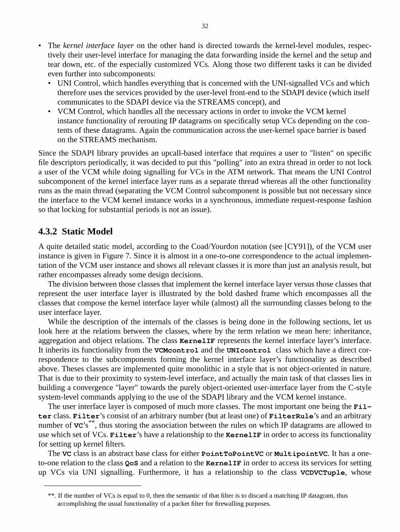
32
pec-p andvided
ichitself
con- based
ecificlocktroltionalityry sincefashion
userlemen-ult, but
ses thatall the
g to the
let usritance,e.
-cribednature.lies in-style
e
ed to
g
• The kernel interface layeron the other hand is directed towards the kernel-level modules, restively their user-level interface for managing the data forwarding inside the kernel and the setutear down, etc. of the especially customized VCs. Along those two different tasks it can be dieven further into subcomponents:• UNI Control, which handles everything that is concerned with the UNI-signalled VCs and wh
therefore uses the services provided by the user-level front-end to the SDAPI device (whichcommunicates to the SDAPI device via the STREAMS concept), and
• VCM Control, which handles all the necessary actions in order to invoke the VCM kernelinstance functionality of rerouting IP datagrams on specifically setup VCs depending on thetents of these datagrams. Again the communication across the user-kernel space barrier ison the STREAMS mechanism.
Since the SDAPI library provides an upcall-based interface that requires a user to "listen" on spfile descriptors periodically, it was decided to put this "polling" into an extra thread in order to nota user of the VCM while doing signalling for VCs in the ATM network. That means the UNI Consubcomponent of the kernel interface layer runs as a separate thread whereas all the other funcruns as the main thread (separating the VCM Control subcomponent is possible but not necessathe interface to the VCM kernel instance works in a synchronous, immediate request-responseso that locking for substantial periods is not an issue).
4.3.2 Static Model
A quite detailed static model, according to the Coad/Yourdon notation (see [CY91]), of the VCMinstance is given in Figure 7. Since it is almost in a one-to-one correspondence to the actual imptation of the VCM user instance and shows all relevant classes it is more than just an analysis resrather encompasses already some design decisions.
The division between those classes that implement the kernel interface layer versus those clasrepresent the user interface layer is illustrated by the bold dashed frame which encompassesclasses that compose the kernel interface layer while (almost) all the surrounding classes belonuser interface layer.
While the description of the internals of the classes is being done in the following sections,look here at the relations between the classes, where by the term relation we mean here: inheaggregation and object relations. The classKernelIF represents the kernel interface layer’s interfacIt inherits its functionality from theVCMcontrol and theUNIcontrol class which have a direct correspondence to the subcomponents forming the kernel interface layer’s functionality as desabove. Theses classes are implemented quite monolithic in a style that is not object-oriented inThat is due to their proximity to system-level interface, and actually the main task of that classesbuilding a convergence "layer" towards the purely object-oriented user-interface layer from the Csystem-level commands applying to the use of the SDAPI library and the VCM kernel instance.
The user interface layer is composed of much more classes. The most important one being thFil-ter class.Filter ’s consist of an arbitrary number (but at least one) ofFilterRule ’s and an arbitrarynumber ofVC’s** , thus storing the association between the rules on which IP datagrams are allowuse which set of VCs.Filter ’s have a relationship to theKernelIF in order to access its functionalityfor setting up kernel filters.
TheVCclass is an abstract base class for eitherPointToPointVC or MultipointVC . It has a one-to-one relation to the classQoSand a relation to theKernelIF in order to access its services for settinup VCs via UNI signalling. Furthermore, it has a relationship to the classVCDVCTuple, whose
**. If the number of VCs is equal to 0, then the semantic of that filter is to discard a matching IP datagram, thusaccomplishing the usual functionality of a packet filter for firewalling purposes.
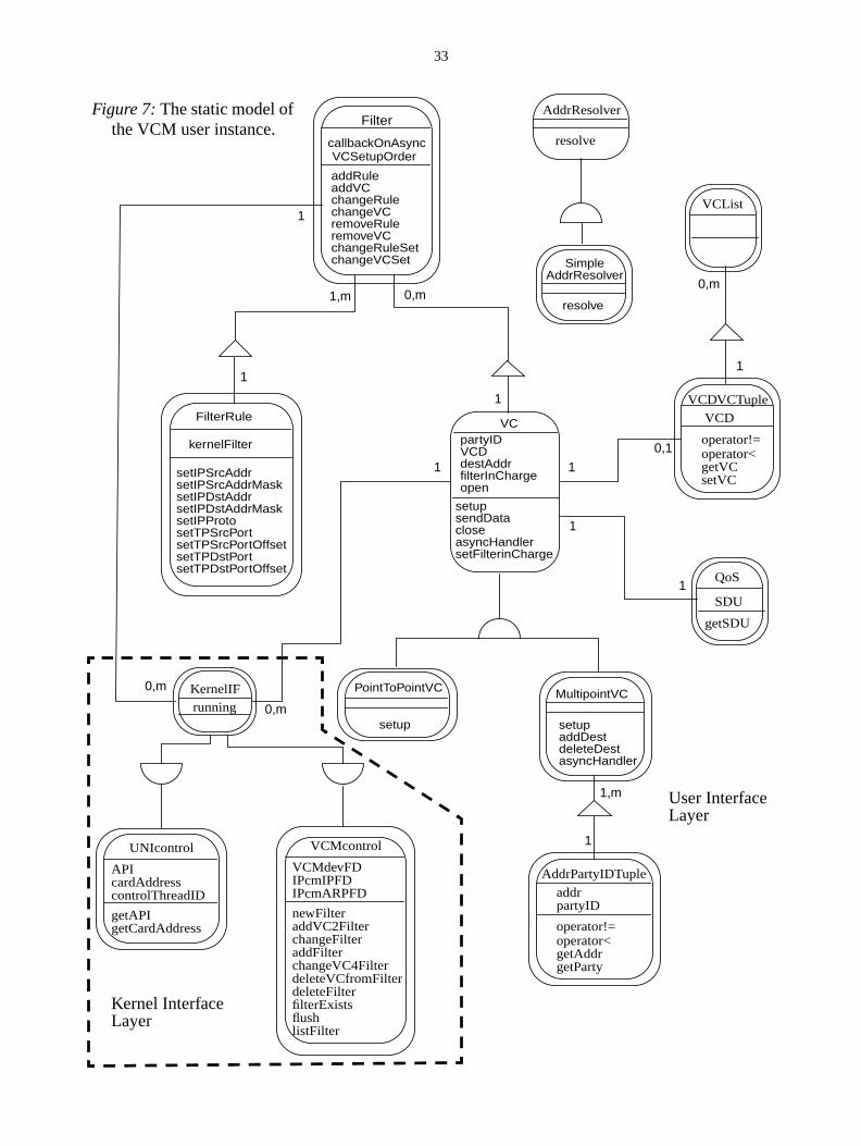
33
callbackOnAsync
Filter
addRuleaddVCchangeRulechangeVCremoveRuleremoveVCchangeRuleSetchangeVCSet
VCSetupOrder
kernelFilter
FilterRule
setIPSrcAddrsetIPSrcAddrMasksetIPDstAddrsetIPDstAddrMasksetIPProtosetTPSrcPortsetTPSrcPortOffsetsetTPDstPortsetTPDstPortOffset
VCpartyIDVCD
setupsendDatacloseasyncHandlersetFilterinCharge
destAddrfilterInChargeopen
AddrResolver
resolve
MultipointVC
setupaddDestdeleteDestasyncHandler
AddrPartyIDTuple
addrpartyID
operator<getAddrgetParty
operator!=
KernelIFrunning
APIcardAddresscontrolThreadID
UNIcontrol
getAPIgetCardAddress
VCMdevFDIPcmIPFD
VCMcontrol
newFilteraddVC2Filter
IPcmARPFD
changeFilteraddFilterchangeVC4FilterdeleteVCfromFilterdeleteFilterfilterExistsflushlistFilter
QoS
SDU
getSDU
VCDVCTupleVCD
operator<getVCsetVC
operator!=
SimpleAddrResolver
resolve
PointToPointVC
setup
VCList
Figure 7:The static model ofthe VCM user instance.
1
0,m
1,m
1
1
0,m
1
0,1
1
1
0,m
1
1,m
1
0,m
1
Kernel InterfaceLayer
User InterfaceLayer
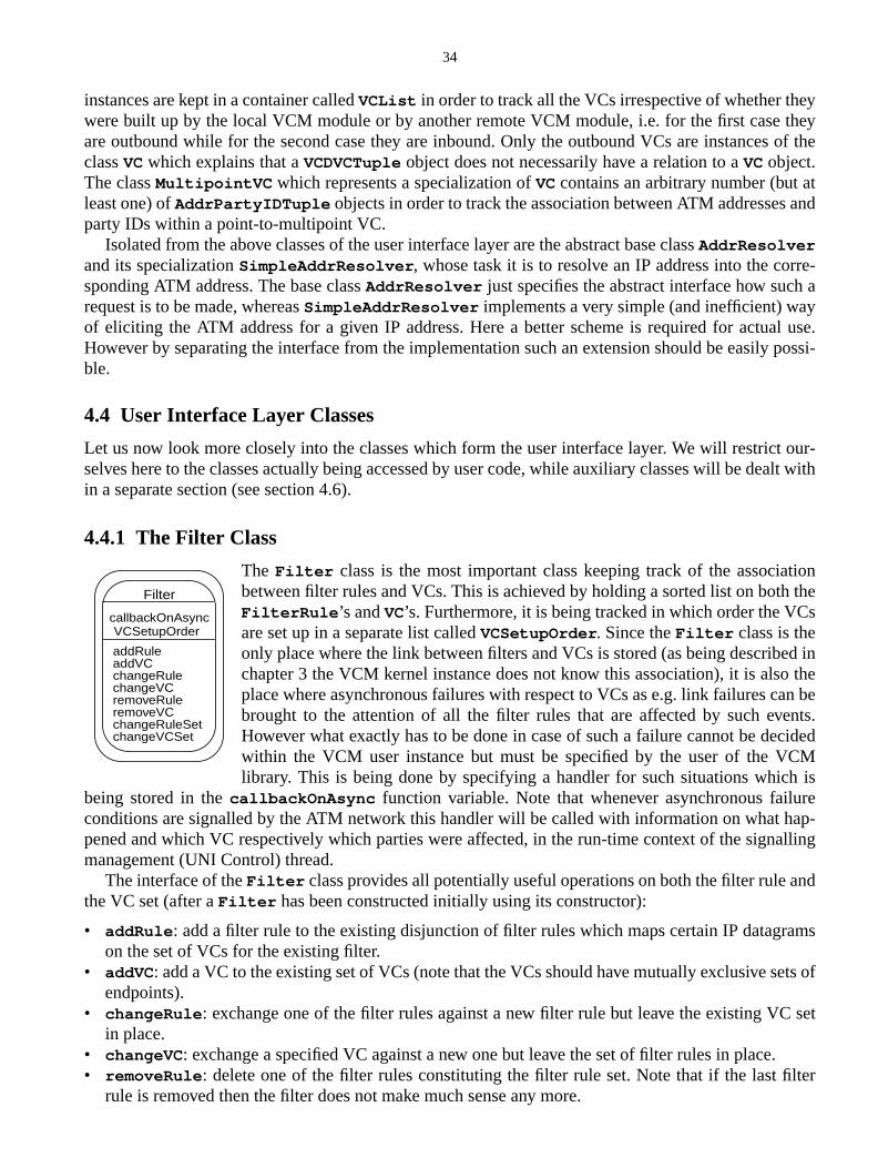
34
ytheys of the
tand
re-a
yl use.possi-
our-alt with
tionthes
ed inthen bents.cidedCMh isreap-alling
nd
ams
ets of
set
.lter
instances are kept in a container calledVCList in order to track all the VCs irrespective of whether thewere built up by the local VCM module or by another remote VCM module, i.e. for the first caseare outbound while for the second case they are inbound. Only the outbound VCs are instanceclassVCwhich explains that aVCDVCTuple object does not necessarily have a relation to aVCobject.The classMultipointVC which represents a specialization ofVCcontains an arbitrary number (but aleast one) ofAddrPartyIDTuple objects in order to track the association between ATM addressesparty IDs within a point-to-multipoint VC.
Isolated from the above classes of the user interface layer are the abstract base classAddrResolverand its specializationSimpleAddrResolver , whose task it is to resolve an IP address into the corsponding ATM address. The base classAddrResolver just specifies the abstract interface how suchrequest is to be made, whereasSimpleAddrResolver implements a very simple (and inefficient) waof eliciting the ATM address for a given IP address. Here a better scheme is required for actuaHowever by separating the interface from the implementation such an extension should be easilyble.
4.4 User Interface Layer Classes
Let us now look more closely into the classes which form the user interface layer. We will restrictselves here to the classes actually being accessed by user code, while auxiliary classes will be dein a separate section (see section 4.6).
4.4.1 The Filter Class
The Filter class is the most important class keeping track of the associabetween filter rules and VCs. This is achieved by holding a sorted list on bothFilterRule ’s andVC’s. Furthermore, it is being tracked in which order the VCare set up in a separate list calledVCSetupOrder . Since theFilter class is theonly place where the link between filters and VCs is stored (as being describchapter 3 the VCM kernel instance does not know this association), it is alsoplace where asynchronous failures with respect to VCs as e.g. link failures cabrought to the attention of all the filter rules that are affected by such eveHowever what exactly has to be done in case of such a failure cannot be dewithin the VCM user instance but must be specified by the user of the Vlibrary. This is being done by specifying a handler for such situations whic
being stored in thecallbackOnAsync function variable. Note that whenever asynchronous failuconditions are signalled by the ATM network this handler will be called with information on what hpened and which VC respectively which parties were affected, in the run-time context of the signmanagement (UNI Control) thread.
The interface of theFilter class provides all potentially useful operations on both the filter rule athe VC set (after aFilter has been constructed initially using its constructor):
• addRule : add a filter rule to the existing disjunction of filter rules which maps certain IP datagron the set of VCs for the existing filter.
• addVC: add a VC to the existing set of VCs (note that the VCs should have mutually exclusive sendpoints).
• changeRule : exchange one of the filter rules against a new filter rule but leave the existing VCin place.
• changeVC : exchange a specified VC against a new one but leave the set of filter rules in place• removeRule : delete one of the filter rules constituting the filter rule set. Note that if the last fi
rule is removed then the filter does not make much sense any more.
callbackOnAsync
Filter
addRuleaddVCchangeRulechangeVCremoveRuleremoveVCchangeRuleSetchangeVCSet
VCSetupOrder
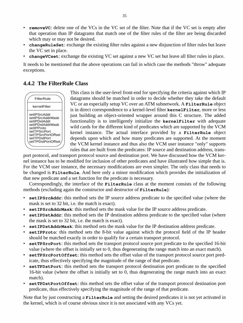
35
fterarded
ave
lace.
equate
h IPefault
ded
M
mentortstrans-M ker-that is.eeds toof
g
re the
where
.ader
16-bitatch).red-
cifiedexact
port
in
• removeVC: delete one of the VCs in the VC set of the filter. Note that if the VC set is empty athat operation than IP datagrams that match one of the filter rules of the filter are being discwhich may or may not be desired.
• changeRuleSet : exchange the existing filter rules against a new disjunction of filter rules but lethe VC set in place.
• changeVCset : exchange the existing VC set against a new VC set but leave all filter rules in p
It needs to be mentioned that the above operations can fail in which case the methods "throw" adexceptions.
4.4.2 The FilterRule Class
This class is the user-level front-end for specifying the criteria against whicdatagrams should be matched in order to decide whether they take the dVC or an especially setup VC over an ATM subnetwork. AFilterRule objectis in direct correspondence to a kernel-level filterkernelFilter , more or lessjust building an object-oriented wrapper around this C structure. The adfunctionality is to intelligently initialize thekernelFilter with adequatewild cards for the different kind of predicates which are supported by the VCkernel instance. The actual interface provided by aFilterRule objectdepends upon which and how many predicates are supported. At the mothe VCM kernel instance and thus also the VCM user instance "only" supprules that are built from the predicates: IP source and destination address,
port protocol, and transport protocol source and destination port. We have discussed how the VCnel instance has to be modified for inclusion of other predicates and have illustrated how simpleFor the VCM user instance, the necessary modifications are even simpler. The only class that nbe changed isFilterRule . And here only a minor modification which provides the initializationthat new predicate and a set function for the predicate is necessary.
Correspondingly, the interface of theFilterRule class at the moment consists of the followinmethods (excluding again the constructor and destructor ofFilterRule ):
• setIPSrcAddr : this method sets the IP source address predicate to the specified value (whemask is set to 32 bit, i.e. the match is exact).
• setIPSrcAddrMask : this method sets the mask value for the IP source address predicate.• setIPDstAddr : this method sets the IP destination address predicate to the specified value (
the mask is set to 32 bit, i.e. the match is exact).• setIPDstAddrMask : this method sets the mask value for the IP destination address predicate• setIPProto : this method sets the 8-bit value against which the protocol field of the IP he
should be matched exactly in order to qualify for a certain transport protocol.• setTPSrcPort : this method sets the transport protocol source port predicate to the specified
value (where the offset is initially set to 0, thus degenerating the range match into an exact m• setTPSrcPortOffset : this method sets the offset value of the transport protocol source port p
icate, thus effectively specifying the magnitude of the range of that predicate.• setTPDstPort : this method sets the transport protocol destination port predicate to the spe
16-bit value (where the offset is initially set to 0, thus degenerating the range match into anmatch).
• setTPDstPortOffset : this method sets the offset value of the transport protocol destinationpredicate, thus effectively specifying the magnitude of the range of that predicate.
Note that by just constructing aFilterRule and setting the desired predicates it is not yet activatedthe kernel, which is of course obvious since it is not associated with any VCs yet.
kernelFilter
FilterRule
setIPSrcAddrsetIPSrcAddrMasksetIPDstAddrsetIPDstAddrMasksetIPProtosetTPSrcPortsetTPSrcPortOffsetsetTPDstPortsetTPDstPortOffset
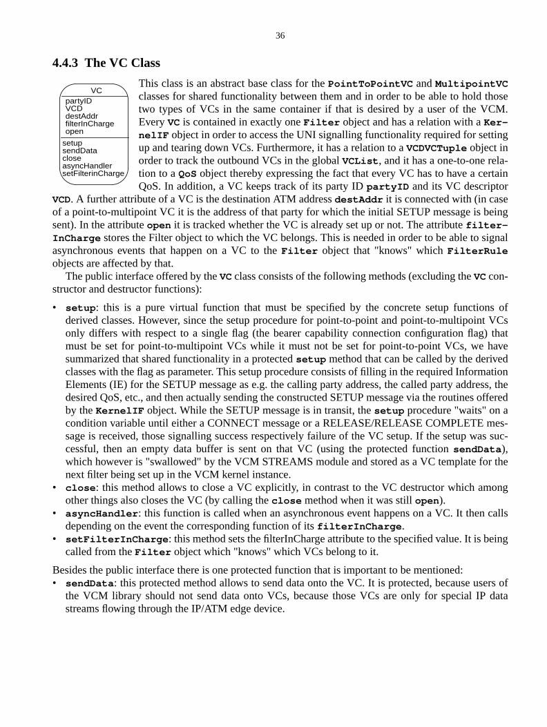
36
thoseM.
ing
-rtain
eing
ignal
s oft VCsthat
avedation
ess, theoffered
es-s suc-
r the
ong
calls
eing
ers ofdata
4.4.3 The VC Class
This class is an abstract base class for thePointToPointVC andMultipointVCclasses for shared functionality between them and in order to be able to holdtwo types of VCs in the same container if that is desired by a user of the VCEveryVC is contained in exactly oneFilter object and has a relation with aKer-nelIF object in order to access the UNI signalling functionality required for settup and tearing down VCs. Furthermore, it has a relation to aVCDVCTuple object inorder to track the outbound VCs in the globalVCList , and it has a one-to-one relation to aQoSobject thereby expressing the fact that every VC has to have a ceQoS. In addition, a VC keeps track of its party IDpartyID and its VC descriptor
VCD. A further attribute of a VC is the destination ATM addressdestAddr it is connected with (in caseof a point-to-multipoint VC it is the address of that party for which the initial SETUP message is bsent). In the attributeopen it is tracked whether the VC is already set up or not. The attributefilter-InCharge stores the Filter object to which the VC belongs. This is needed in order to be able to sasynchronous events that happen on a VC to theFilter object that "knows" whichFilterRuleobjects are affected by that.
The public interface offered by theVCclass consists of the following methods (excluding theVCcon-structor and destructor functions):
• setup : this is a pure virtual function that must be specified by the concrete setup functionderived classes. However, since the setup procedure for point-to-point and point-to-multipoinonly differs with respect to a single flag (the bearer capability connection configuration flag)must be set for point-to-multipoint VCs while it must not be set for point-to-point VCs, we hsummarized that shared functionality in a protectedsetup method that can be called by the deriveclasses with the flag as parameter. This setup procedure consists of filling in the required InformElements (IE) for the SETUP message as e.g. the calling party address, the called party addrdesired QoS, etc., and then actually sending the constructed SETUP message via the routinesby theKernelIF object. While the SETUP message is in transit, thesetup procedure "waits" on acondition variable until either a CONNECT message or a RELEASE/RELEASE COMPLETE msage is received, those signalling success respectively failure of the VC setup. If the setup wacessful, then an empty data buffer is sent on that VC (using the protected functionsendData ),which however is "swallowed" by the VCM STREAMS module and stored as a VC template fonext filter being set up in the VCM kernel instance.
• close : this method allows to close a VC explicitly, in contrast to the VC destructor which amother things also closes the VC (by calling theclose method when it was stillopen ).
• asyncHandler : this function is called when an asynchronous event happens on a VC. It thendepending on the event the corresponding function of itsfilterInCharge .
• setFilterInCharge : this method sets the filterInCharge attribute to the specified value. It is bcalled from theFilter object which "knows" which VCs belong to it.
Besides the public interface there is one protected function that is important to be mentioned:• sendData : this protected method allows to send data onto the VC. It is protected, because us
the VCM library should not send data onto VCs, because those VCs are only for special IPstreams flowing through the IP/ATM edge device.
VCpartyIDVCD
setupsendDatacloseasyncHandlersetFilterinCharge
destAddrfilterInChargeopen
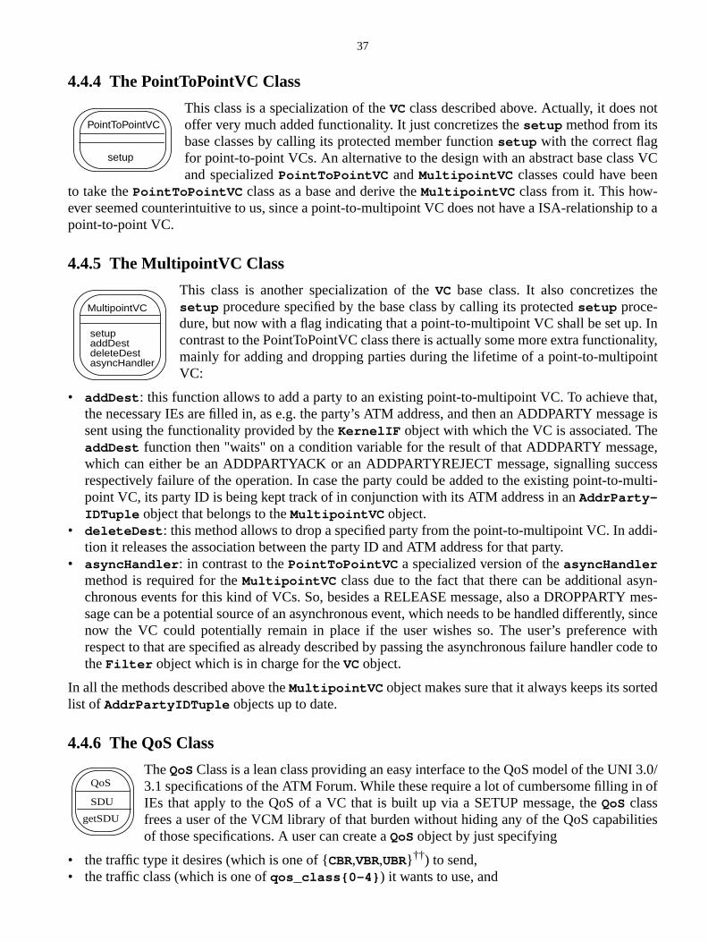
37
ot
VCn
ip to a
e
. Inality,int
at,age is
ege,cessmulti-
di-
yn-mes-
ly, sincewithcode to
ed
I 3.0/n of
ities
4.4.4 The PointToPointVC Class
This class is a specialization of theVCclass described above. Actually, it does noffer very much added functionality. It just concretizes thesetup method from itsbase classes by calling its protected member functionsetup with the correct flagfor point-to-point VCs. An alternative to the design with an abstract base classand specializedPointToPointVC andMultipointVC classes could have bee
to take thePointToPointVC class as a base and derive theMultipointVC class from it. This how-ever seemed counterintuitive to us, since a point-to-multipoint VC does not have a ISA-relationshpoint-to-point VC.
4.4.5 The MultipointVC Class
This class is another specialization of theVC base class. It also concretizes thsetup procedure specified by the base class by calling its protectedsetup proce-dure, but now with a flag indicating that a point-to-multipoint VC shall be set upcontrast to the PointToPointVC class there is actually some more extra functionmainly for adding and dropping parties during the lifetime of a point-to-multipoVC:
• addDest : this function allows to add a party to an existing point-to-multipoint VC. To achieve ththe necessary IEs are filled in, as e.g. the party’s ATM address, and then an ADDPARTY messsent using the functionality provided by theKernelIF object with which the VC is associated. ThaddDest function then "waits" on a condition variable for the result of that ADDPARTY messawhich can either be an ADDPARTYACK or an ADDPARTYREJECT message, signalling sucrespectively failure of the operation. In case the party could be added to the existing point-to-point VC, its party ID is being kept track of in conjunction with its ATM address in anAddrParty-IDTuple object that belongs to theMultipointVC object.
• deleteDest : this method allows to drop a specified party from the point-to-multipoint VC. In adtion it releases the association between the party ID and ATM address for that party.
• asyncHandler : in contrast to thePointToPointVC a specialized version of theasyncHandlermethod is required for theMultipointVC class due to the fact that there can be additional aschronous events for this kind of VCs. So, besides a RELEASE message, also a DROPPARTYsage can be a potential source of an asynchronous event, which needs to be handled differentnow the VC could potentially remain in place if the user wishes so. The user’s preferencerespect to that are specified as already described by passing the asynchronous failure handlertheFilter object which is in charge for theVC object.
In all the methods described above theMultipointVC object makes sure that it always keeps its sortlist of AddrPartyIDTuple objects up to date.
4.4.6 The QoS Class
TheQoSClass is a lean class providing an easy interface to the QoS model of the UN3.1 specifications of the ATM Forum. While these require a lot of cumbersome filling iIEs that apply to the QoS of a VC that is built up via a SETUP message, theQoS classfrees a user of the VCM library of that burden without hiding any of the QoS capabilof those specifications. A user can create aQoS object by just specifying
• the traffic type it desires (which is one of {CBR,VBR,UBR} ††) to send,• the traffic class (which is one ofqos_class{0-4} ) it wants to use, and
PointToPointVC
setup
MultipointVC
setupaddDestdeleteDestasyncHandler
QoS
SDU
getSDU
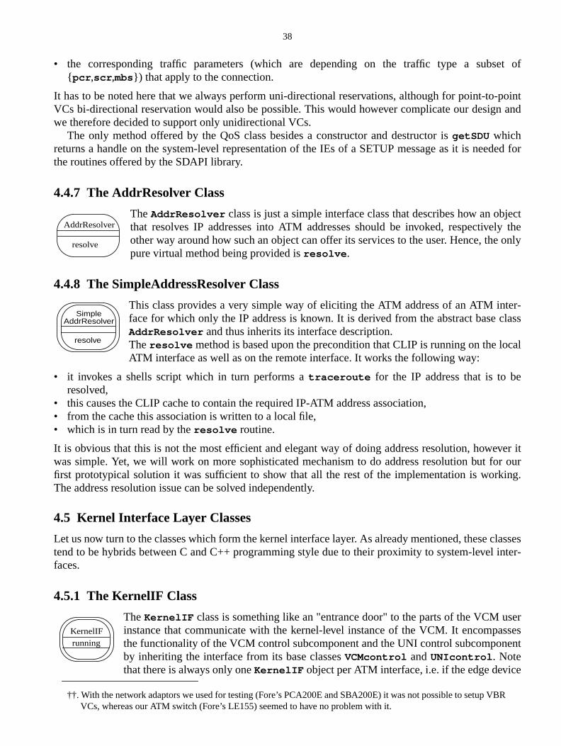
38
et of
-pointn and
ded for
jectly the
only
er-class
cal
ver itr ouring.
classesinter-
serssesent
e
R
• the corresponding traffic parameters (which are depending on the traffic type a subs{ pcr ,scr ,mbs}) that apply to the connection.
It has to be noted here that we always perform uni-directional reservations, although for point-toVCs bi-directional reservation would also be possible. This would however complicate our desigwe therefore decided to support only unidirectional VCs.
The only method offered by the QoS class besides a constructor and destructor isgetSDU whichreturns a handle on the system-level representation of the IEs of a SETUP message as it is neethe routines offered by the SDAPI library.
4.4.7 The AddrResolver Class
TheAddrResolver class is just a simple interface class that describes how an obthat resolves IP addresses into ATM addresses should be invoked, respectiveother way around how such an object can offer its services to the user. Hence, thepure virtual method being provided isresolve .
4.4.8 The SimpleAddressResolver Class
This class provides a very simple way of eliciting the ATM address of an ATM intface for which only the IP address is known. It is derived from the abstract baseAddrResolver and thus inherits its interface description.Theresolve method is based upon the precondition that CLIP is running on the loATM interface as well as on the remote interface. It works the following way:
• it invokes a shells script which in turn performs atraceroute for the IP address that is to beresolved,
• this causes the CLIP cache to contain the required IP-ATM address association,• from the cache this association is written to a local file,• which is in turn read by theresolve routine.
It is obvious that this is not the most efficient and elegant way of doing address resolution, howewas simple. Yet, we will work on more sophisticated mechanism to do address resolution but fofirst prototypical solution it was sufficient to show that all the rest of the implementation is workThe address resolution issue can be solved independently.
4.5 Kernel Interface Layer Classes
Let us now turn to the classes which form the kernel interface layer. As already mentioned, thesetend to be hybrids between C and C++ programming style due to their proximity to system-levelfaces.
4.5.1 The KernelIF Class
TheKernelIF class is something like an "entrance door" to the parts of the VCM uinstance that communicate with the kernel-level instance of the VCM. It encompathe functionality of the VCM control subcomponent and the UNI control subcomponby inheriting the interface from its base classesVCMcontrol andUNIcontrol . Notethat there is always only oneKernelIF object per ATM interface, i.e. if the edge devic
††. With the network adaptors we used for testing (Fore’s PCA200E and SBA200E) it was not possible to setup VBVCs, whereas our ATM switch (Fore’s LE155) seemed to have no problem with it.
AddrResolver
resolve
SimpleAddrResolver
resolve
KernelIFrunning
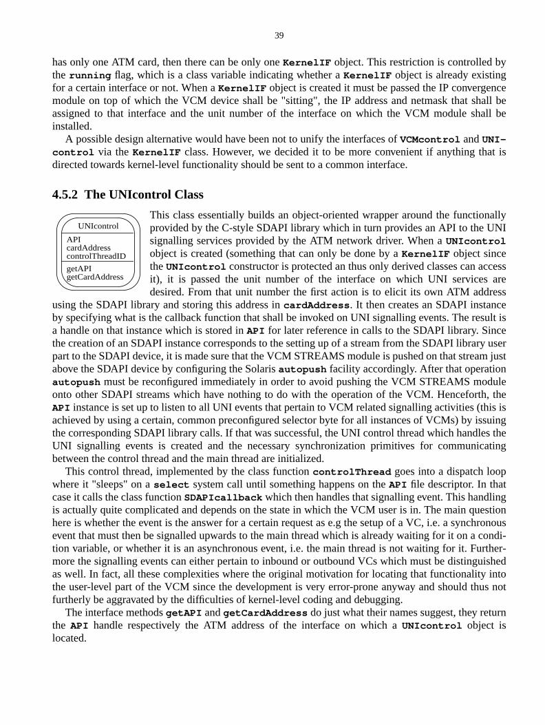
39
nceall beall be
t is
nallyNI
cessareesseult isey userm just
ule, theis issuings theating
ngestionhronouscondi-rther-ished
intous not
rn
has only one ATM card, then there can be only oneKernelIF object. This restriction is controlled bythe running flag, which is a class variable indicating whether aKernelIF object is already existingfor a certain interface or not. When aKernelIF object is created it must be passed the IP convergemodule on top of which the VCM device shall be "sitting", the IP address and netmask that shassigned to that interface and the unit number of the interface on which the VCM module shinstalled.
A possible design alternative would have been not to unify the interfaces ofVCMcontrol andUNI-control via theKernelIF class. However, we decided it to be more convenient if anything thadirected towards kernel-level functionality should be sent to a common interface.
4.5.2 The UNIcontrol Class
This class essentially builds an object-oriented wrapper around the functioprovided by the C-style SDAPI library which in turn provides an API to the Usignalling services provided by the ATM network driver. When aUNIcontrolobject is created (something that can only be done by aKernelIF object sincetheUNIcontrol constructor is protected an thus only derived classes can acit), it is passed the unit number of the interface on which UNI servicesdesired. From that unit number the first action is to elicit its own ATM addr
using the SDAPI library and storing this address incardAddress . It then creates an SDAPI instancby specifying what is the callback function that shall be invoked on UNI signalling events. The resa handle on that instance which is stored inAPI for later reference in calls to the SDAPI library. Sincthe creation of an SDAPI instance corresponds to the setting up of a stream from the SDAPI librarpart to the SDAPI device, it is made sure that the VCM STREAMS module is pushed on that streaabove the SDAPI device by configuring the Solarisautopush facility accordingly. After that operationautopush must be reconfigured immediately in order to avoid pushing the VCM STREAMS modonto other SDAPI streams which have nothing to do with the operation of the VCM. HenceforthAPI instance is set up to listen to all UNI events that pertain to VCM related signalling activities (thachieved by using a certain, common preconfigured selector byte for all instances of VCMs) by isthe corresponding SDAPI library calls. If that was successful, the UNI control thread which handleUNI signalling events is created and the necessary synchronization primitives for communicbetween the control thread and the main thread are initialized.
This control thread, implemented by the class functioncontrolThread goes into a dispatch loopwhere it "sleeps" on aselect system call until something happens on theAPI file descriptor. In thatcase it calls the class functionSDAPIcallback which then handles that signalling event. This handliis actually quite complicated and depends on the state in which the VCM user is in. The main quhere is whether the event is the answer for a certain request as e.g the setup of a VC, i.e. a syncevent that must then be signalled upwards to the main thread which is already waiting for it on ation variable, or whether it is an asynchronous event, i.e. the main thread is not waiting for it. Fumore the signalling events can either pertain to inbound or outbound VCs which must be distinguas well. In fact, all these complexities where the original motivation for locating that functionalitythe user-level part of the VCM since the development is very error-prone anyway and should thfurtherly be aggravated by the difficulties of kernel-level coding and debugging.
The interface methodsgetAPI andgetCardAddress do just what their names suggest, they retuthe API handle respectively the ATM address of the interface on which aUNIcontrol object islocated.
APIcardAddresscontrolThreadID
UNIcontrol
getAPIgetCardAddress
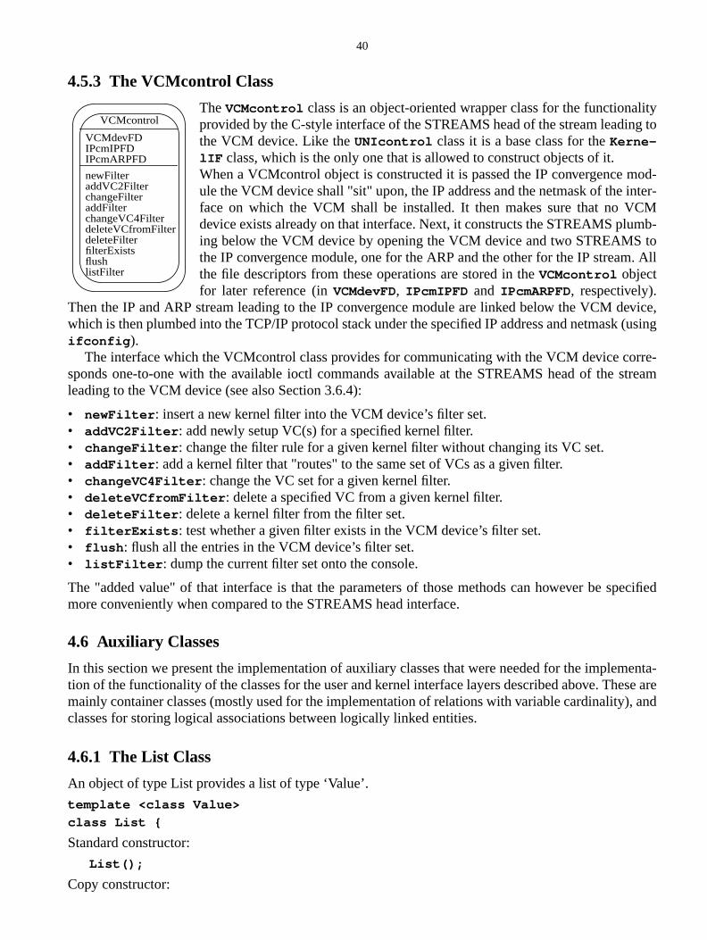
40
lityg to
od-ter-M
mb-to. All
evice,(using
rre-tream
ecified
menta-ese are), and
4.5.3 The VCMcontrol Class
TheVCMcontrol class is an object-oriented wrapper class for the functionaprovided by the C-style interface of the STREAMS head of the stream leadinthe VCM device. Like theUNIcontrol class it is a base class for theKerne-lIF class, which is the only one that is allowed to construct objects of it.When a VCMcontrol object is constructed it is passed the IP convergence mule the VCM device shall "sit" upon, the IP address and the netmask of the inface on which the VCM shall be installed. It then makes sure that no VCdevice exists already on that interface. Next, it constructs the STREAMS pluing below the VCM device by opening the VCM device and two STREAMSthe IP convergence module, one for the ARP and the other for the IP streamthe file descriptors from these operations are stored in theVCMcontrol objectfor later reference (inVCMdevFD, IPcmIPFD and IPcmARPFD, respectively).
Then the IP and ARP stream leading to the IP convergence module are linked below the VCM dwhich is then plumbed into the TCP/IP protocol stack under the specified IP address and netmaskifconfig ).
The interface which the VCMcontrol class provides for communicating with the VCM device cosponds one-to-one with the available ioctl commands available at the STREAMS head of the sleading to the VCM device (see also Section 3.6.4):
• newFilter : insert a new kernel filter into the VCM device’s filter set.• addVC2Filter : add newly setup VC(s) for a specified kernel filter.• changeFilter : change the filter rule for a given kernel filter without changing its VC set.• addFilter : add a kernel filter that "routes" to the same set of VCs as a given filter.• changeVC4Filter : change the VC set for a given kernel filter.• deleteVCfromFilter : delete a specified VC from a given kernel filter.• deleteFilter : delete a kernel filter from the filter set.• filterExists : test whether a given filter exists in the VCM device’s filter set.• flush : flush all the entries in the VCM device’s filter set.• listFilter : dump the current filter set onto the console.
The "added value" of that interface is that the parameters of those methods can however be spmore conveniently when compared to the STREAMS head interface.
4.6 Auxiliary Classes
In this section we present the implementation of auxiliary classes that were needed for the impletion of the functionality of the classes for the user and kernel interface layers described above. Thmainly container classes (mostly used for the implementation of relations with variable cardinalityclasses for storing logical associations between logically linked entities.
4.6.1 The List Class
An object of type List provides a list of type ‘Value’.
template <class Value>
class List {
Standard constructor:
List();
Copy constructor:
VCMdevFDIPcmIPFD
VCMcontrol
newFilteraddVC2Filter
IPcmARPFD
changeFilteraddFilterchangeVC4FilterdeleteVCfromFilterdeleteFilterfilterExistsflushlistFilter
41
a con-nt con-of typevali-
List( const List& l );
Destructor:
~List();
Assignment operator:
List& operator=( const List& l );
Compare operations:
bool operator==( const List& l ) const;
bool operator!=( const List& l ) const;
Class Iterator and ConstIterator provide a similar interface and can be used to iterate throughtainer having access to its elements. ConstIterator have to be used for iterating through a constatainer object. Consequently the dereference-operator returns a reference to a constant object‘Value’. When removing an element from a container, all iterators pointing to that element are indated and must not be used anymore.
class Container::Iterator {
Iterator();
Iterator& operator++();
Iterator& operator--();
Value& operator*() const;
operator== ( const Iterator& i ) const;
operator!= ( const Iterator& i ) const;
};
Empty the list:
void clear();
Insert element at beginning of list:
void push_front( const Value& elem );
Remove first element:
void pop_front();
Append element at rear end:
void push_back( const Value& elem );
Remove last element:
void pop_back();
Access first element:
Value& front();
const Value& front() const;
Access last element:
Value& back();
const Value& back() const;
Get iterator pointing to first element:
Iterator begin();
ConstIterator begin() const;
Get iterator pointing to last element:
Iterator end();
42
theused
rsion
y’. A
both,
wing
list,
ment
ConstIterator end() const;
Insert element before ‘pos’. Returns iterator pointing to a new element:
Iterator insert( ConstIterator pos, const Value& elem );
Erase element at ‘pos’. Returns iterator pointing to next element after ‘pos’:
Iterator erase( ConstIterator pos );
Insert range of elements from another list, before ‘pos’:
void insert( ConstIterator pos,ConstIterator first, ConstIterator last );
Erase range of elements. Returns iterator pointing to next element after last deleted:
Iterator erase( ConstIterator first, ConstIterator last )
Number of elements:
unsigned int size() const;
Boolean value to indicate whether container is empty:
bool empty() const;
};
4.6.2 The SortedList Class
An object of type SortedList provides a sortable list of its value type. Type ‘Key’ should be set tosame type as ‘Value’ to indicate that the ordering is inherent to the value type. If a different key isto access elements of a list, type ‘Value’ must either be inherited from ‘Key’ or provide a conveoperator to type ‘Key’. The type ‘Compare’ must be a class adhering to the following interface:
struct CompareType {
operator bool( const Key&, const Key& );
};
The boolean function operator must model the ‘less than’ relation between two objects of type ‘Kestandard compare class exists, named ‘Less’, which uses the default ‘less than’ operator.
Given the requirements above for ’Key’ and ‘Value’, access methods (find, erase, etc.) can takean element or a key as an argument.
template <class Value, class Key, class Compare>
class SortedList : public List<Value> {
SortedList provides with some restrictions the interface of class List and additionally, the follomethods are exported:
Find an element ‘elem’. Returns an iterator pointing to that element. If ‘elem’ does not exist in thean iterator to the next-larger element is returned.
ConstIterator lower_bound( const Key& elem ) const;
Find an element ‘elem’. Returns an iterator pointing to that element. Returns point to ‘end()’, if eleis not found.
ConstIterator find( const Key& elem ) const;
Find or insert an element ‘elem’. Returns an iterator pointing to that element.
ConstIterator find_or_insert_sorted( const Value& elem );
Boolean value to indicate whether a sorted list contains a specific element:
bool contains( const Key& key ) const;
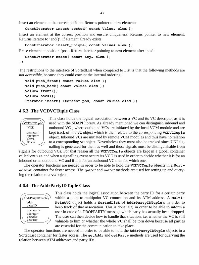
43
lement.
s are
it isandare
tionsig-fromrr an
y-
arty
rm apped.
stillrties
e
Insert an element at the correct position. Returns pointer to new element:
ConstIterator insert_sorted( const Value& elem );
Insert an element at the correct position and ensure uniqueness. Returns pointer to new eReturns iterator to ‘end()’, if element already exists:
ConstIterator insert_unique( const Value& elem );
Erase element at position ‘pos’. Returns iterator pointing to next element after ‘pos’:
ConstIterator erase( const Key& elem );
};
The restrictions to the interface of SortedList when compared to List is that the following methodnot accessible, because they could corrupt the internal ordering:
void push_front( const Value& elem );
void push_back( const Value& elem );
Value& front();
Value& back();
Iterator insert( Iterator pos, const Value& elem );
4.6.3 The VCDVCTuple Class
This class holds the logical association between a VC and its VC descriptor asused with the SDAPI library. As already mentioned we can distinguish inboundoutbound VCs, where outbound VCs are initiated by the local VCM module andkept track of in aVCobject which is then related to the correspondingVCDVCTupleobject. Inbound VCs are initiated by remote VCM modules and thus have no relato a correspondingVCobject. Nevertheless they must also be tracked since UNInalling is generated for them as well and those signals must be distinguishable
signals for outbound VCs. For that reason all theVCDVCTuple objects are kept in a global containecalledVCList and when a signalling event occurs its VCD is used in order to decide whether it is foinbound or an outbound VC and if it is for an outbound VC then for which one.
The operator functions are needed in order to be able to hold theVCDVCTuple objects in aSort-edList container for faster access. ThegetVC andsetVC methods are used for setting up and quering the relation to aVC object.
4.6.4 The AddrPartyIDTuple Class
This class holds the logical association between the party ID for a certain pwithin a point-to-multipoint VC connection and its ATM address. AMulti-PointVC object holds aSortedList of AddrPartyIDTuple ’s in order tokeep track of that association. This is done, e.g. in order to be able to infouser in case of a DROPPARTY message which party has actually been droThe user can then decide how to handle that situation, i.e. whether the VC isvaluable to him or whether the whole VC shall be torn down because all paare essential for the communication to take place.
The operator functions are needed in order to be able to hold theAddrPartyIDTuple objects in aSortedList container for faster access. ThegetAddr andgetParty methods are used for querying threlation between ATM addresses and party IDs.
VCDVCTupleVCD
operator<getVCsetVC
operator!=
AddrPartyIDTuple
addrpartyID
operator<getAddrgetParty
operator!=
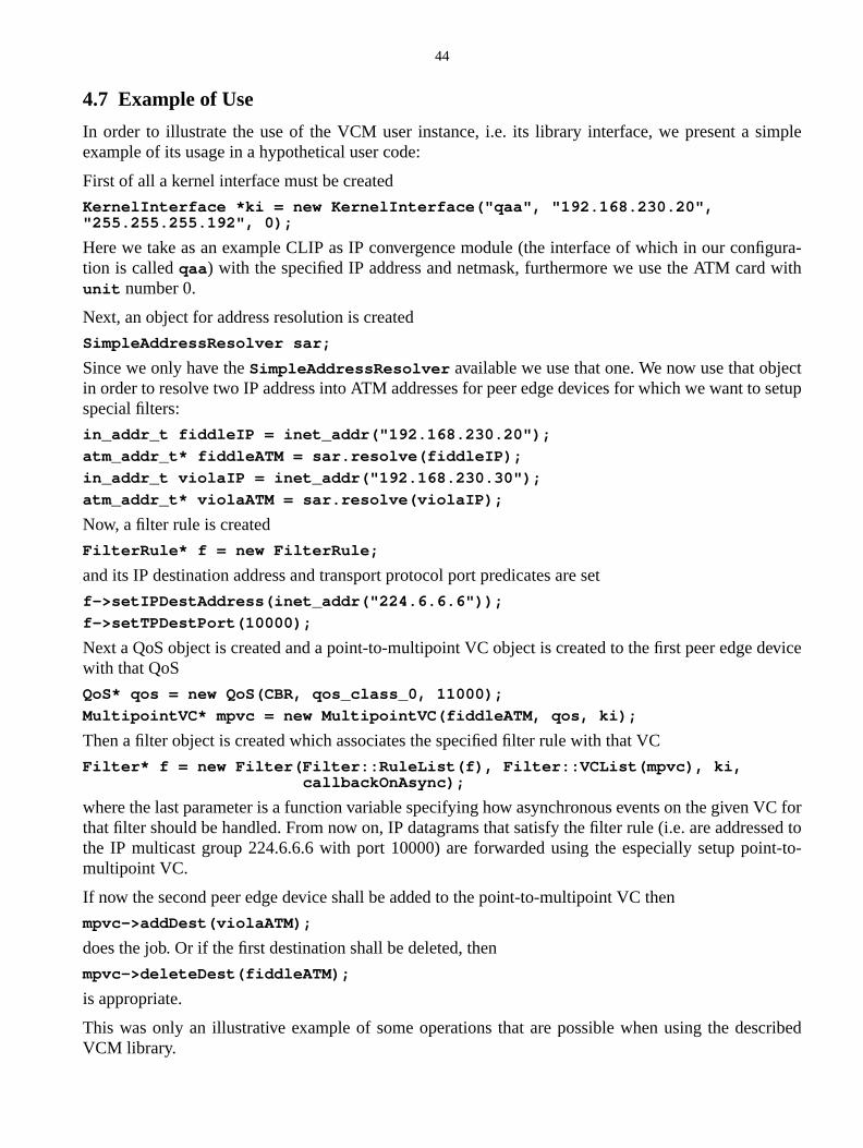
44
imple
figura-with
ctsetup
device
VC forsed to
int-to-
cribed
4.7 Example of Use
In order to illustrate the use of the VCM user instance, i.e. its library interface, we present a sexample of its usage in a hypothetical user code:
First of all a kernel interface must be created
KernelInterface *ki = new KernelInterface("qaa", "192.168.230.20","255.255.255.192", 0);
Here we take as an example CLIP as IP convergence module (the interface of which in our contion is calledqaa ) with the specified IP address and netmask, furthermore we use the ATM cardunit number 0.
Next, an object for address resolution is created
SimpleAddressResolver sar;
Since we only have theSimpleAddressResolver available we use that one. We now use that objein order to resolve two IP address into ATM addresses for peer edge devices for which we want tospecial filters:
in_addr_t fiddleIP = inet_addr("192.168.230.20");
atm_addr_t* fiddleATM = sar.resolve(fiddleIP);
in_addr_t violaIP = inet_addr("192.168.230.30");
atm_addr_t* violaATM = sar.resolve(violaIP);
Now, a filter rule is created
FilterRule* f = new FilterRule;
and its IP destination address and transport protocol port predicates are set
f->setIPDestAddress(inet_addr("224.6.6.6"));
f->setTPDestPort(10000);
Next a QoS object is created and a point-to-multipoint VC object is created to the first peer edgewith that QoS
QoS* qos = new QoS(CBR, qos_class_0, 11000);
MultipointVC* mpvc = new MultipointVC(fiddleATM, qos, ki);
Then a filter object is created which associates the specified filter rule with that VC
Filter* f = new Filter(Filter::RuleList(f), Filter::VCList(mpvc), ki,callbackOnAsync);
where the last parameter is a function variable specifying how asynchronous events on the giventhat filter should be handled. From now on, IP datagrams that satisfy the filter rule (i.e. are addresthe IP multicast group 224.6.6.6 with port 10000) are forwarded using the especially setup pomultipoint VC.
If now the second peer edge device shall be added to the point-to-multipoint VC then
mpvc->addDest(violaATM);
does the job. Or if the first destination shall be deleted, then
mpvc->deleteDest(fiddleATM);
is appropriate.
This was only an illustrative example of some operations that are possible when using the desVCM library.
45
dap-sed
. Theglobalternalto thedesignthisce effi-
wherease out all
pathnly wille tool
can bethe
wasP/Int-with
goalsection
over-pro-entialis now
level,y spe-
s will
5 SummaryIn this report we provided a detailed description of the design and implementation of an IP/ATM atation module which allows to leverage the QoS facilities provided by ATM for an overlaid IP-banetwork. This description was structured according to the internal structure of the VCM moduleVCM module is divided into a user instance and a kernel instance. In chapter 2 we provided theview on the interworking of those two, before we gave detailed descriptions of each and their incomponents in chapter 3 and chapter 4. While the kernel instance is designed accordingSTREAMS paradigm and implemented using the C programming language, the user instance’sis object-oriented offering a library interface for the C++ programming language. We think thathybrid design suits the respective needs of those two distinct instances best, since in kernel spaciency and ease of use of existing interfaces has preference over elegant design and reusability,for the user instance those two metrics are crucial ones. One goal of the design was also to sourccomplex operations which are non-critical with respect to performance on the data forwardingfrom kernel into user space. That ensured maximum ease of development and coding and certaiensure this for future modifications as well, thus making the IP/ATM adaptation module a valuablfor further experimentation with IP/ATM edge device functionality.
The adaptation module was intentionally designed as flexible and general as possible so that itused for virtually any "QoS signal" given by the IP network in order to trigger special handling byATM network. Our motivation to do so was that while overlaying the RSVP/IntServ architecturethe motivation to develop such an adaptation module in the first place it is conceivable that RSVServ will only be one of several "tools" within IP-based networks for users to convey their desiresregard to QoS provisioning by the network. Thus flexibility was one of the most important designfor the IP/ATM adaptation module and has been like all the other design goals that were set in S2.2 achieved from our point of view.
We think that together with the sophisticated solution approaches devised in [SKWS98] for thelaying of RSVP/IntServ onto ATM networks which were also partially implemented for our formertotype implementation (see Appendix), the IP/ATM adaptation module now also provides the potto support those approaches on the data path in a performant manner. Thus a complete solutionachievable by the integration of those two parts. Of course, this still remains on a prototypicalsince many of the operations of an actual production-level IP/ATM edge device will be assisted bcial hardware. However, the overall architecture should remain the same and the same algorithmbe applicable.
46
NIX
vicesrt of
Four
tianl
ATM
over
uting
References[CY91] P. Coad and E. Yourdon. Object-Oriented Analysis, 1991. Prentice Hall, Englewood Cliffs.[OSI91] OSI Work Group. Data Link Provider Interface Specification Rev. 2.0.0, August 1991. UInternational.[SKWS98] Jens Schmitt, Martin Karsten, Lars Wolf, and Ralf Steinmetz. Internet Integrated SerMulticast on ATM Networks and RSVP Extensions for Charging, August 1998. 1st Milestone RepoIQATM Project (Phase 2).[Sun95] SunSoft. STREAMS Programmer’s Guide , November 1995.[Sun96] SunSoft. Writing Device Drivers , August 1996.[SVSW98] S. Srinivasan, G. Varghese, S. Suri, and M. Waldvogel. Fast and Scalable LayerSwitching. InProceedings of SIGCOMM’98. ACM, September 1998.[SWK+99] Jens Schmitt, Lars Wolf, Martin Karsten, Ralf Steinmetz, Yann-Olivier Lorcy, and ChrisSiebel. Shortcutting IP Flows over Large ATM Networks. InProceedings of the 2nd IEEE InternationaConference on on ATM (ICATM’99), Colmar, France. IEEE, June 21–23 1999.[SWS97a] Jens Schmitt, Lars Wolf, and Ralf Steinmetz. Interaction Approaches for Internet andQuality of Service Architectures , June 1997. 2nd Milestone Report of IQATM Project (Phase 1).[SWS97b] Jens Schmitt, Lars Wolf, and Ralf Steinmetz. Design and Implementation of an RSVPATM Prototype, October 1997. 3rd Milestone Report of IQATM Project (Phase 1).[WVTP97] M. Waldvogel, G. Varghese, J. Turner, and B. Plattner. Scalable High Speed IP RoLookups. InProceedings of SIGCOMM’97. ACM, September 1997.