Embed Size (px)
Citation preview

DARE Institute of Space Technology1
MS THESIS
Distance Aware Relaying Energy-efficient: (DARE) to Monitor Patients in Multi-hop Body
Area Networks
Presenter:Anum [email protected]
Supervisors:Principle Supervisor: Dr. Nadeem Javaid (CAST-CIIT) Co-Supervisor: Dr. Aamir Habib (IST)

DARE Institute of Space Technology2
Outline
• Introduction
• Motivation
• Distance Aware Relaying Energy-efficient (DARE)
– Implementation, results and conclusion
• Non-Invasive Inductive Link Model for Pacemakers
– Implementation, results and conclusion

DARE Institute of Space Technology3
Introduction
• Wireless Body Area Network (WBAN)
– Network of sensors
• Implement communications on, near, and around the human body
• Applications
– Medical field
– Aerospace
– Sports and Entertainment etc.
In-VivoPacemaker: to monitor heart patients.
WearableSensor analyzing motion of a
body.
Types of sensors
DARE Institute of Space Technology4
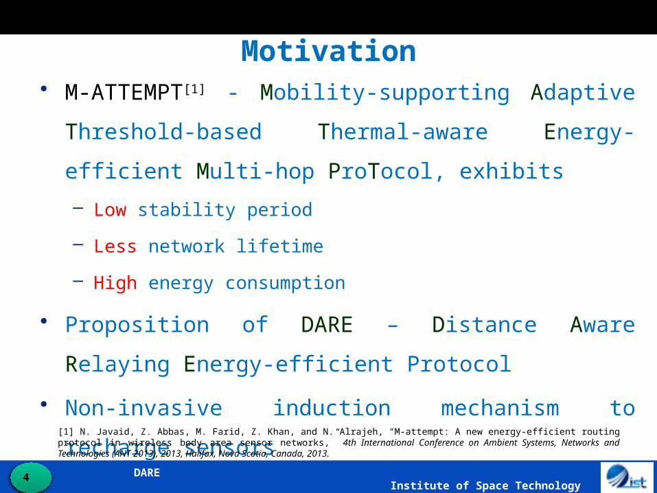
Motivation• M-ATTEMPT[1] - Mobility-supporting Adaptive Threshold-
based Thermal-aware Energy-efficient Multi-hop ProTocol,
exhibits
– Low stability period
– Less network lifetime
– High energy consumption
• Proposition of DARE – Distance Aware Relaying Energy-
efficient Protocol
• Non-invasive induction mechanism to recharge sensors[1] N. Javaid, Z. Abbas, M. Farid, Z. Khan, and N. Alrajeh, “M-attempt: A new energy-efficient routing protocol in wireless body area sensor networks,” 4th International Conference on Ambient Systems, Networks and Technologies (ANT 2013), 2013, Halifax, Nova Scotia, Canada, 2013.

DARE Institute of Space Technology5
Proposed Scheme: DAREBlock Diagram
Different sink
scenarios
Basic schematic diagram of protocol operation.• BSs - Detect physical parameters under low parameters.
• BRs - Act as forwarders of data from BSs to BRs to MS/Sink (Mobile Phone).• Sink – External monitoring system (server, desktop).
• MS - A type of sink device with either unlimited or at least very high energy resources (PDA).
Twothreshold monitoring
sensors(Glucose,
Temperature)
Fivecontinuous monitoring
sensors(ECG, Heart rate, Pulse
rate, Motions, Toxins)
Body Sensors (BSs)
Body Relay(BR)
ExternalNetwork
S1
S2
S3
S4
S5
SinkOr
Main Sensor (MS)
Collect Data
Append Data
Transmit
Data

DARE Institute of Space Technology6
Proposed Scheme: DARE Sensor’s Deployment
Sensors deployment on patient measuring, seven different parameters along with a relay node (BR) placed on chest.
Hospital ward - 40 x 20 ft2
Eight patients Variable sensor types -
standard deployment of sensors (sensing sensors)
Five scenarios (Sinks may be static or mobile)
Distance changes energy consumption
Different energy parameters Mobility in patient

DARE Institute of Space Technology7
Proposed Scheme: DARE Communication Flow
If EBS > 0
Stops monitoring
For all BSs
If EBR > 0
If BS= th
If lo/h
i
BS=cont
Measure Eres,d,tpd
Yes
Yes
No
No Yes
Yes
NoNo
BSs = body sensors EBS = energy of body
sensor EBR = energy of body
relay th = threshold lo = low threshold hi = high threshold cont = continuous Eres = residual energy d = distance between
sensors tpd = propagation delay Temperature threshold
= 350C -- 400C Glucose threshold =
110mg/dL -- 125mg/dL
Protocol Operation for monitoring a patient.
Monitoring a patent

DARE Institute of Space Technology8
Proposed Scheme: DARE Scenario-1
Deploys single static sink. The communication flow is from BSs to BR to sink.
Continuous data monitoring sensors(BSs)
Event-driven data monitoring sensors(BSs)
Body Relay (BR)
Sink
DARE Institute of Space Technology9
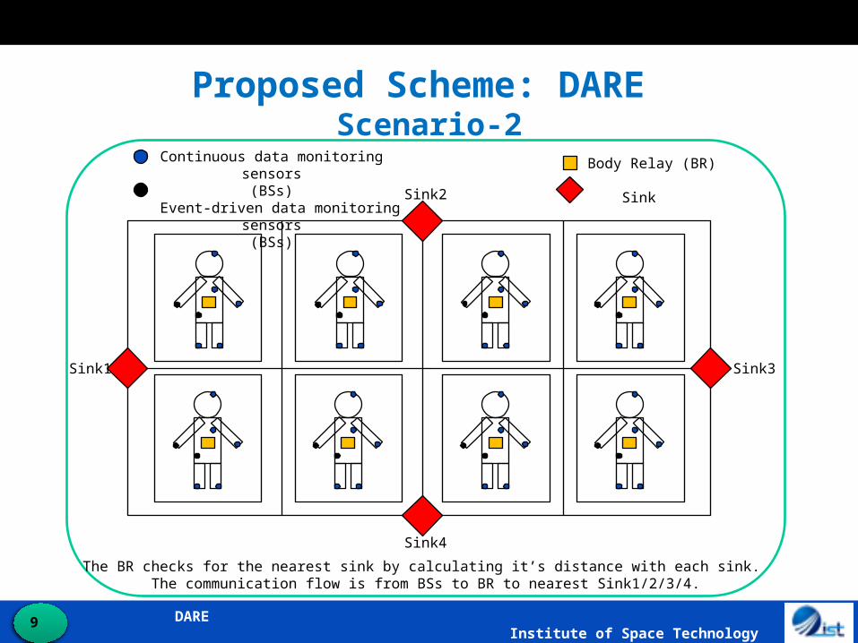
Proposed Scheme: DARE Scenario-2
The BR checks for the nearest sink by calculating it’s distance with each sink. The communication flow is from BSs to BR to nearest Sink1/2/3/4.
Continuous data monitoring sensors(BSs)
Event-driven data monitoring sensors(BSs)
Body Relay (BR)
Sink
Sink1
Sink2
Sink3
Sink4

DARE Institute of Space Technology10
Proposed Scheme: DARE Scenario-3
The deployment of MS helps the BR to consume little energy as, BR transmits data over shorter distance. Communication flow is from BSs to BR to MS to Sink.
Continuous data monitoring sensors(BSs)
Event-driven data monitoring sensors(BSs)
Body Relay (BR)
SinkMain Sensor (MS)

DARE Institute of Space Technology11
Proposed Scheme: DARE Scenario-4
Continuous data monitoring sensors(BSs)
Event-driven data monitoring sensors(BSs)
Body Relay (BR)
Sink
3 1
2
It follows the same communication flow as sceanrio-1 however, now the sink is made mobile which, moves along the center of ward.

DARE Institute of Space Technology12
Proposed Scheme: DARE Scenario-5
Multiple sinks move around the walls of the ward altogether. The BR communicates with the nearest sink. The communication flow is from BSs to BR to the nearest moving Sink1/2/3/4.
Continuous data monitoring sensors(BSs)
Event-driven data monitoring sensors(BSs)
Body Relay (BR)
Sink
Sink1
Sink2
Sink3
Sink4
1 3
2
3
1
2
1
3
212
3

DARE Institute of Space Technology13
ComparisonM-ATTEMPT and DARE
Sensors deployment on proposed DARE protocol and compared M-ATTEMPT protocol.
M-ATTEMPT Patient
DARE Patient

DARE Institute of Space Technology14
Results for Static PatientsAlive Nodes
DARE’s scenario-5, incorporates multiple moving sinks. BRs reduce the energy consumption of nodes.

DARE Institute of Space Technology15
Number of Received Packets
The probability for receiving packets with success is set to be 0.7. Sink mobility in scenario-5 let the network to continue operation for more rounds and
let network to receive huge number of packets.
DARE Institute of Space Technology16
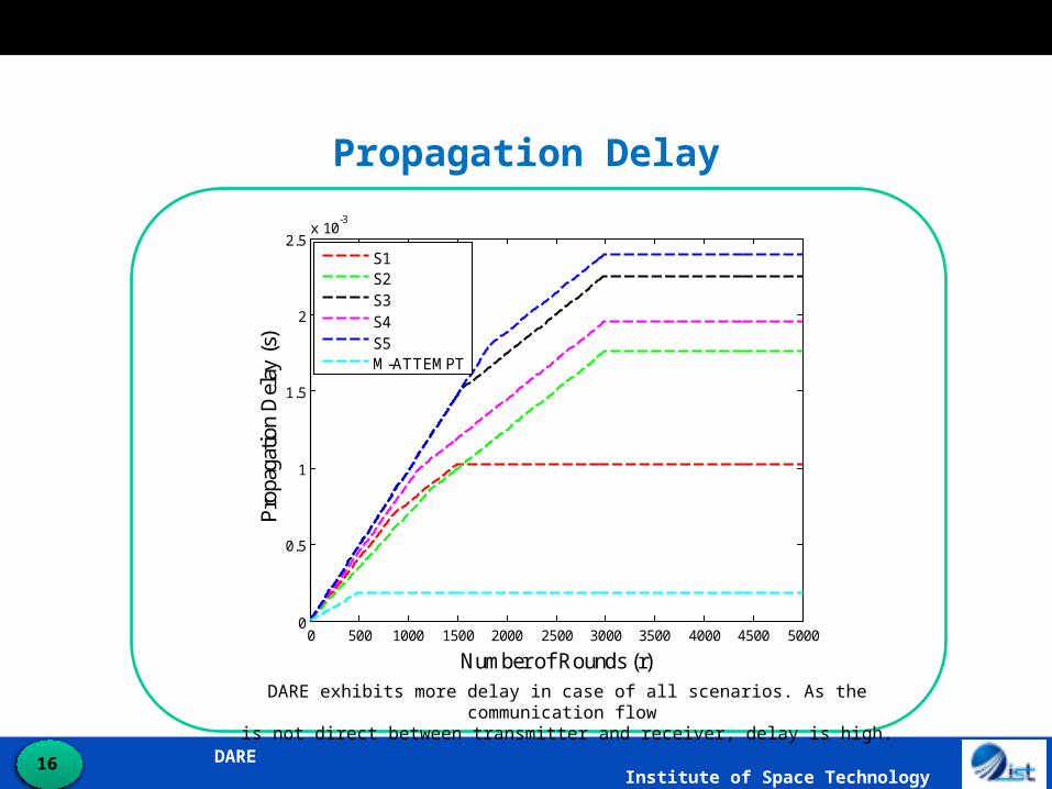
Propagation Delay
DARE exhibits more delay in case of all scenarios. As the communication flow is not direct between transmitter and receiver, delay is high.
0 500 1000 1500 2000 2500 3000 3500 4000 4500 50000
0.5
1
1.5
2
2.5x 10
-3
Number of Rounds (r)
Pro
paga
tion
Del
ay (
s)
S1S2S3S4S5M-ATTEMPT
DARE Institute of Space Technology17
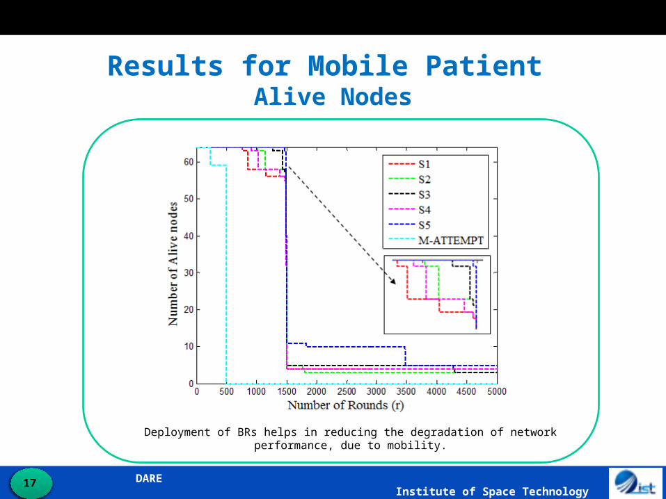
Results for Mobile Patient Alive Nodes
Deployment of BRs helps in reducing the degradation of network performance, due to mobility.
DARE Institute of Space Technology18
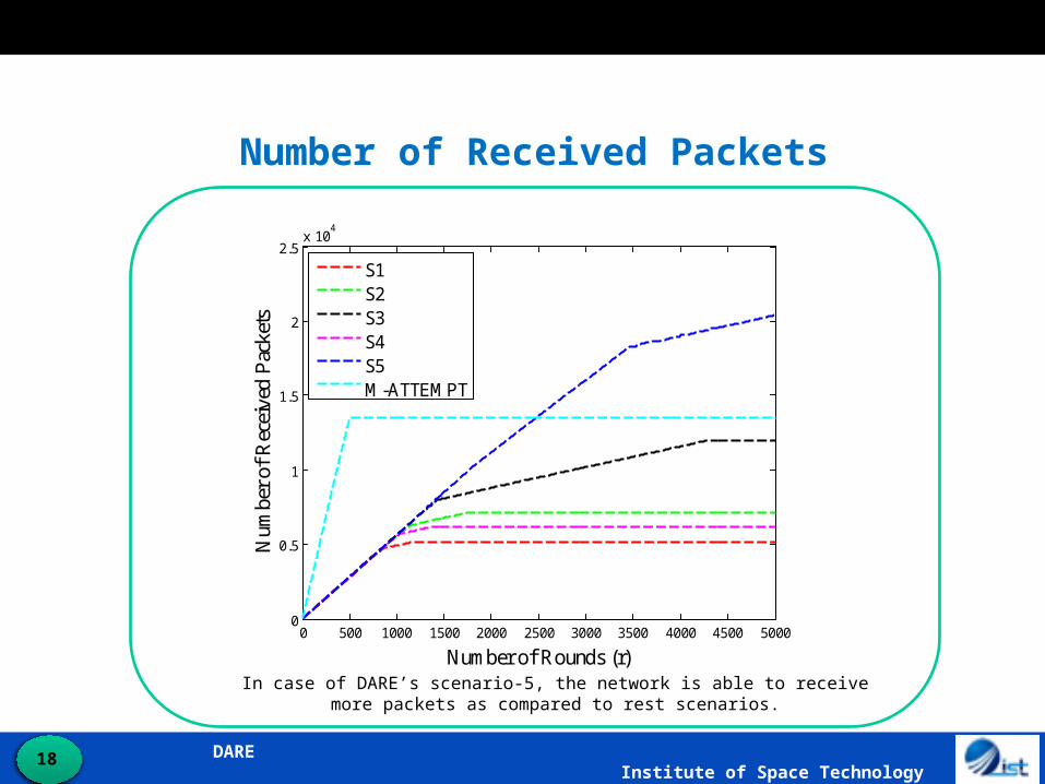
Number of Received Packets
In case of DARE’s scenario-5, the network is able to receive more packets as compared to rest scenarios.
0 500 1000 1500 2000 2500 3000 3500 4000 4500 50000
0.5
1
1.5
2
2.5x 10
4
Number of Rounds (r)
Num
ber
of R
ecei
ved
Pac
kets
S1S2S3S4S5M-ATTEMPT

DARE Institute of Space Technology19
Propagation Delay
DARE exhibits more delay in case of all scenarios as compared to M-ATTEMPT.

DARE Institute of Space Technology20
DARE vs. M-ATTEMPT
Network Parameter DARE M-ATTEMPT
Stability Period high low
Network Lifetime high low
Energy Consumption minimum maximum
Throughput high low
Propagation Delay high low

DARE Institute of Space Technology21
Non-Invasive Induction to Recharge Sensors
• Aim is to
– Recharge pacemakers sensor’s battery
• Avoid frequent surgical operations and battery failure
• Extend working duration of sensors
– Pacemakers
• Create forced rhythms
– Natural human heart beats in
arrhythmic patients
Schematic view of an inductive linkPrimary side inducing voltage to regulate power at
secondary side (implanted inside human body).

DARE Institute of Space Technology22
Induction Models
A capacitor is connected in series at primary side, in order to induce
sufficient amount of voltage to the secondary coil.
A capacitor C2p has been connected in parallel at secondary side, making a low pass filter which, allows low frequencies to pass through while,
blocking the higher frequencies, thereby, preventing damages to body tissues.
MHz56.13f,320R,45.0k
LLkM
load
21
Series Tuned Primary Circuit (STPC)
Series Tuned Primary and Parallel Tuned Secondary Circuit
(STPPTSC)
[2] G. B. Hmida, H. Ghariani, and M. Samet. “Design of wireless power and data transmission circuits for implantable biomicrosystem,” Biotechnology, vol. 6, no. 2, 2007, pp. 153–164.
[2]

DARE Institute of Space Technology23
Link ParametersSTPC STPPTSC
22load
s
load
MwAB
jwMR
V
V
)Mw]BRe[]A](Re[BRe[
RMw22
load22
)Mw]CRe[]A](Re[CRe[
]ZRe[Mw22
load22
222L2load
load
s
load
Mw)RjwLZ(A
jwMZ
V
V
load2L
2
RR
fL2Q
load
1
R
fL2Q
Voltage Gain
Link Efficiency
Quality Factor
[1]
[3] [4]
[5] [6]
[2]

DARE Institute of Space Technology24
ResultsVoltage Gain
As, k increases Vload/Vs increases. Vload increases by about 2 times than Vs.
Vload increases by about 3 times than Vs.
STPC STPPTSC
0 50 100 150 200 250 300 350 4000
1
2
3
4
5
6
Rload
(Ohms)V
olta
ge G
ain
( V lo
ad /
Vs )
k = 0.2k = 0.4k = 0.6k = 0.8
0 50 100 150 200 250 300 350 4000
0.5
1
1.5
2
2.5
3
3.5
4
4.5
5
Rload
(Ohms)
Vol
tage
Gai
n (
Vlo
ad /
Vs )
k = 0.2k = 0.4k = 0.6k = 0.8

DARE Institute of Space Technology25
ResultsLink Efficiency
STPC STPPTSC
As, k increases η increases and is about 75%.
η increases by 15%, i.e. 90% of the input power has been efficiently transferred to
the secondary side.
0 50 100 150 200 250 300 350 4000
0.1
0.2
0.3
0.4
0.5
0.6
0.7
0.8
0.9
1
Rload
(Ohms)
Lin
k E
ffic
ienc
y (
P 2 / P
1)
k = 0.2k = 0.4k = 0.6k = 0.8
0 50 100 150 200 250 300 350 4000
0.1
0.2
0.3
0.4
0.5
0.6
0.7
0.8
0.9
1
Rload
(Ohms)
Lin
k E
ffic
ienc
y (
P 2 / P
1)
k = 0.2k = 0.4k = 0.6k = 0.8

DARE Institute of Space Technology26
ResultsQuality Factor
In case of STPPTSC, the Q factor is higher as compared to STPC. Thus, achieves good tuning under
resonant conditions at f= 13.56 MHz.
0 0.5 1 1.5 2 2.5 3 3.5
x 107
0
0.2
0.4
0.6
0.8
1
1.2
1.4
Frequency (Hz)
Qua
lity
Fac
tor
Series CircuitParallel Circuit
DARE Institute of Space Technology27
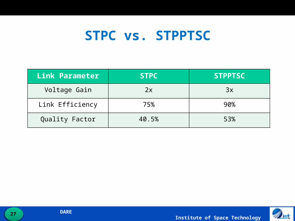
STPC vs. STPPTSC
Link Parameter STPC STPPTSC
Voltage Gain 2x 3x
Link Efficiency 75% 90%
Quality Factor 40.5% 53%

DARE Institute of Space Technology28
DARE Institute of Space Technology29
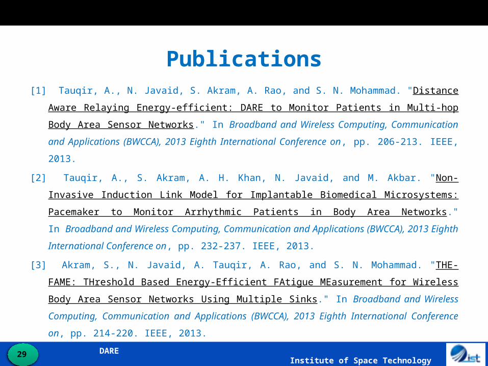
Publications[1] Tauqir, A., N. Javaid, S. Akram, A. Rao, and S. N. Mohammad. "Distance Aware Relaying Energy-
efficient: DARE to Monitor Patients in Multi-hop Body Area Sensor Networks." In Broadband and
Wireless Computing, Communication and Applications (BWCCA), 2013 Eighth International
Conference on, pp. 206-213. IEEE, 2013.
[2] Tauqir, A., S. Akram, A. H. Khan, N. Javaid, and M. Akbar. "Non-Invasive Induction Link Model for
Implantable Biomedical Microsystems: Pacemaker to Monitor Arrhythmic Patients in Body Area
Networks." In Broadband and Wireless Computing, Communication and Applications (BWCCA),
2013 Eighth International Conference on, pp. 232-237. IEEE, 2013.
[3] Akram, S., N. Javaid, A. Tauqir, A. Rao, and S. N. Mohammad. "THE-FAME: THreshold Based
Energy-Efficient FAtigue MEasurement for Wireless Body Area Sensor Networks Using Multiple
Sinks." In Broadband and Wireless Computing, Communication and Applications (BWCCA), 2013
Eighth International Conference on, pp. 214-220. IEEE, 2013.