Embed Size (px)
Citation preview

6Flat B 607, 6/F, Jumbo Ind Bldg, 189 Wai Yip Street, Kwun Tong, KLN ,HK
(852)30786684 (852)35902333 [email protected] www.ideal-photonics.com
DAQ_card operating Manual
Hardware description:
Synchronization pulse output portADC channel AADC channel BPower supply input portRJ45 communication port
Optional:
Sampling frequency:100MHZChannel Number:2 chADC Resolution:14bitTrigger mode:TTL pulse output (TTL 3.3V) Analog signal input range: 0-1V, and the interface type is SMA Power supply: 5V,2A (notice the right positive and negative electrode)Communication protocol: RJ45 internet port
Figure 1 DAQ card hardware

Description of acquisition card control software:
6Flat B 607, 6/F, Jumbo Ind Bldg, 189 Wai Yip Street, Kwun Tong, KLN ,HK
(852)30786684 (852)35902333 [email protected] www.ideal-photonics.com
1、First, the DAQ card is powered on by 5V DC power supply, and communicated with comput-er through the RJ45 port. LD_CLK is connected to trigger the pulse laser. ADC channel A and B are connected to the output of APD modules.2、Open the software“DAQ_card_control.exe”,then click“System”-“Communication Mode”from the left-top menu. In“Communication Mode”window, you can select “TCP/IP”and then input the correct “Port number” and “IP address”,and then click “Ok”to connect the DAQ card. If you want to disconnect, just click “Cancel”.( The default port number and IP address are 23 and 192.168.0.110 respectively.)
As it is shown in figure 2:
Figure 2 Communication mode setting
3、If connect successfully,the left-bottom corner of the software will show " TCP/IP连接服务器成功"。
4、Then click“Debug Panel” in the lef-top menu,the data curve display and sampling parameter setting window will show as follow:

6Flat B 607, 6/F, Jumbo Ind Bldg, 189 Wai Yip Street, Kwun Tong, KLN ,HK
(852)30786684 (852)35902333 [email protected] www.ideal-photonics.com
Figure 4 The data curve display and sampling parameter setting window
4、“Sampling times”represents average time for each sampling.“Data length”represents sampling data point number. After select setting value, the DAQ card will renew the sampling parameter after you click the corresponding button of “Set”.
5、Data show range and interval setting:
Figure 6 Data show range and interval setting
The first, second and third input number represent the data drawing start position, end position and interval respectively.The above example shown in the figure 6: Data drawing point position from 0 to 8000, and the interval is 1.

6Flat B 607, 6/F, Jumbo Ind Bldg, 189 Wai Yip Street, Kwun Tong, KLN ,HK
(852)30786684 (852)35902333 [email protected] www.ideal-photonics.com
Control command:
Complete command format (all the following value are expressed in hexadecimal):
ef 01 are the fixed command frame headcmd is the command byted1、d2 are the 16-bits data byte
Command 1:Setting the average timescmd:01d1 d2:0000 8192 times 0001 8192*2 times 0002 8192*4 times 0003 8192*8 times ....... ........For example:if average times want to set as 8192,the command is : EF 01 01 00 00 .
Command 2:Setting the sampling data point number(Notice:here the whole sampling data for each frame including invalid reserved data head, tail and valid ADC data)cmd:02d1 d2:represents the sampling data point number. (Hexadecimal format: d1-high byte; d2 -low byte)For example:if sampling point number want to set as 258,the command is : EF 01 02 01 02
Command 3:Start and stop acquiringcmd:03d1 d2:start- 00 01stop- 00 02
Return data format:
When start the acquiring, the return data format is as follow:FD FE XX XX d1_L d1_H d2_L d2_H ⋯⋯ dn_L dn_H XX1 XX2 XX3 XX4 XX5 XX6 XX7 XX8FC FB XX XX d1_L d1_H d2_L d2_H ⋯⋯ dn_L dn_H XX1 XX2 XX3 XX4 XX5 XX6 XX7 XX8
6Flat B 607, 6/F, Jumbo Ind Bldg, 189 Wai Yip Street, Kwun Tong, KLN ,HK
(852)30786684 (852)35902333 [email protected] www.ideal-photonics.com
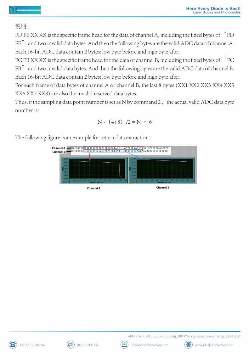
说明:FD FE XX XX is the specific frame head for the data of channel A, including the fixed bytes of “FD FE” and two invalid data bytes. And then the following bytes are the valid ADC data of channel A. Each 16-bit ADC data contain 2 bytes: low byte before and high byte after.FC FB XX XX is the specific frame head for the data of channel B, including the fixed bytes of “FC FB” and two invalid data bytes. And then the following bytes are the valid ADC data of channel B. Each 16-bit ADC data contain 2 bytes: low byte before and high byte after.For each frame of data bytes of channel A or channel B, the last 8 bytes (XX1 XX2 XX3 XX4 XX5 XX6 XX7 XX8) are also the invalid reserved data bytes.Thus, if the sampling data point number is set as N by command 2,the actual valid ADC data byte number is:
N -(4+8)/2 = N – 6
The following figure is an example for return data extraction: