Embed Size (px)
Citation preview

Danvent DV 190 and 240 Air Handling Units with High Capacity
Fans | Air Handling Units | Air Distribution Products | Air Conditioning | Fire Safety | Air Curtains and Heating Products | Tunnel Fans

Danvent DVA modular air handling unit
The Danvent DV 190 and 240 are designed as modular air handling units. Each function is placed into an air handling unit casing consisting of one or more modules. The modular functions can be confi gured for many different applications to make up the heart of any ventilation system.
The Danvent DV 190 and 240 are continually being optimized and added improvements. The result is extremely flexible air handling units, both in terms of design and function.
The air handling units are produced in Denmark. At the Danish Systemair factory we have manufactured air handling units since 1977. Systemair in Denmark houses the group’s expertise for large air handling units. We focus on development, manufacturing, sales, and consultations.
Danvent DV 190 and 240
AHU No 07.02.339DANVENT DV 10-240, TIME 10-40
ENERGY EFFICIENCY
Report to performance data 2014
339
2014
ErP2016
ErP2018
Danvent DV 190 and 240
Functions
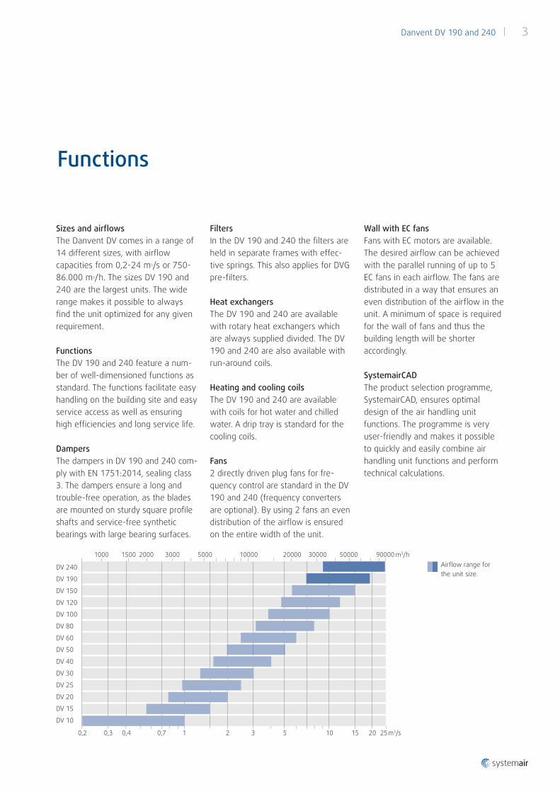
Sizes and airflowsThe Danvent DV comes in a range of 14 different sizes, with airflow capacities from 0,2-24 m3/s or 750-86.000 m3/h. The sizes DV 190 and 240 are the largest units. The wide range makes it possible to always find the unit optimized for any given requirement.
FunctionsThe DV 190 and 240 feature a num-ber of well-dimensioned functions as standard. The functions facilitate easy handling on the building site and easy service access as well as ensuring high efficiencies and long service life.
Dampers The dampers in DV 190 and 240 com-ply with EN 1751:2014, sealing class 3. The dampers ensure a long and trouble-free operation, as the blades are mounted on sturdy square profile shafts and service-free synthetic bearings with large bearing surfaces.
FiltersIn the DV 190 and 240 the filters are held in separate frames with effec-tive springs. This also applies for DVG pre-filters.
Heat exchangersThe DV 190 and 240 are available with rotary heat exchangers which are always supplied divided. The DV 190 and 240 are also available with run-around coils.
Heating and cooling coilsThe DV 190 and 240 are available with coils for hot water and chilled water. A drip tray is standard for the cooling coils.
Fans2 directly driven plug fans for fre-quency control are standard in the DV 190 and 240 (frequency converters are optional). By using 2 fans an even distribution of the airflow is ensured on the entire width of the unit.
Wall with EC fansFans with EC motors are available. The desired airflow can be achieved with the parallel running of up to 5 EC fans in each airflow. The fans are distributed in a way that ensures an even distribution of the airflow in the unit. A minimum of space is required for the wall of fans and thus the building length will be shorter accordingly.
SystemairCADThe product selection programme, SystemairCAD, ensures optimal design of the air handling unit functions. The programme is very user-friendly and makes it possible to quickly and easily combine air handling unit functions and perform technical calculations.
m3/h9000020000 30000 500005000 100001000 300020001500
253210,70,40,30,2 m3/s
DV 10
5 10 15 20
DV 15
DV 20
DV 25
DV 30
DV 40
DV 50
DV 60
DV 80
DV 100
DV 120
DV 150
DV 190
DV 240 Airflow range for the unit size.
Danvent DV 190 and 240 | 3

Functions
SystemairCAD calculates and opti-mizes the energy consumption and the calculated data are the basis for Eurovent certification and energy classification of Danvent DV.
The programme uses a number of combination examples or basic ver-sions. From these examples one can quickly add or remove features in order to easily design the desired air handling unit.
The drawn to scale drawings plus logical construction and presentation of technical data provide easy over-view. The drawings can easily be exported to other CAD software. SystemairCAD has plug-ins for the CAD software MagiCAD for AutoCAD and Revit. The plug-ins make it pos-sible to insert Systemair air handling units directly into MagiCAD, AutoCAD, and Revit. SystemarCAD can be downloaded from systemair.com.
Casing The DV 190 and 240 are built to last for many years. The frame profiles and panels are made of steel sheets protected with alu-zink AZ 185 – pro-viding a good corrosion protection.
Frame profiles and cornersThe DV 190 and 240 are constructed using strong, closed and all-welded steel framing profiles. With the cast aluminium corners the result is a strong and robust construction able to resist twisting and lateral move-ment, making the units extremely stable and strong. PanelsThe panels of the DV 190 and 240 are built using a sandwich construc-tion with double sheets and 50 mm mineral wool for sound and heat insulation. The panels with alu-zinc surface are not only highly corrosion-resistant, but present an attractive, uniform appearance that can last for many years. Steel sheets which are protected with alu-zinc AZ185 ensure a corrosion protection in class C4 according to EN ISO 12944-2:2000. Base frame and sectionsAll DV 190 and 240 sections have a strong and rigid base frame with lift-ing brackets. Some sections may contain more than one function, and these sections will have their own base frames. The base frame is part of the casing, and it is not possible
to demount the base frame. Also for units in 2 levels (supply air and exhaust air in 2 levels) the base frame is necessary under the upper casing to keep the whole unit rigid, and it will ensure easy transport.
Assembly of sectionsThe lifting brackets are removed from the base frames and the base frames are bolted together. Brackets keep the top of the sections together.
Inspection doorsThe DV 190 and 240 have large inspection doors, making service access easy. The doors are mounted using solid hinges with easily remo-vable stainless steel pins. The doors are sealed using rubber profiles and locks with heavy-duty handles. They can only be opened using a key.
Transport and liftThe length of each section does not exceed 2470 mm. For easy internal transport with a fork-lift truck with extra long forks, 100 mm high wood blocks are bolted under each corner of the base frame.
NOTE! Do not under any circumstan-ces lift the section with forks that are shorter than the section!
When the sections are lifted by straps to the final de stination, it must be carried out by using the lifting brackets on the base frame, and dis-tance pipes must be used above the section.Ready to lift. Base frames are connected.
DV with wall of EC fans.
4 | Danvent DV 190 and 240

Combination Examples
The above dimensions and weights are a guideline only. Accurate values and combinations are calculated in SystemairCAD. The heights are incl. base frames.
Rotary heat exchanger 190 240
Unit Width 3190 3490
Rotary heat exchanger section Width 3720 4020
Unit Height 4340 4940
C1 Length 5010 5530
Weight kg 6290 7610
C2 Length 5980 6430
Weight kg 7220 8600
C3 Length 6430 7100
Weight kg 6870 8280
C4 Length 7400 8000
Weight kg 7790 9180
C5 Length 6430 7100
Weight kg 6860 8280
C6 Length 7400 8000
Weight kg 7790 9170
Run-around coil heat exchanger 190 240
Unit Width 3190 3490
Single height unit
Double height unit
Height 2170 2470
Height 4340 4940
R1 Length 5010 5230
Weight kg 6290 7420
R2 Length 5910 6060
Weight kg 7050 8270
Recirculated air 190 240
Unit Width 3190 3490
Single height unit
Double height unit
Height 2170 2470
Height 4340 4940
M1 Length 4410 5080
Weight kg 2320 3040
M2 Length 5380 5980
Weight kg 3250 3940
M3 Length 7550 8820
Weight kg 3930 5100
M4 Length 8520 9720
Weight kg 4850 6000
M5 Length 4710 5080
Weight kg 4190 5150
M6 Length 5680 5980
Weight kg 5110 6050
Supply air 190 240
Unit Width 3190 3490
Single height unit
Double height unit
Height 2170 2470
Height 4340 4940
S1 Length 4040 4260
Weight kg 2250 2820
S2 Length 5010 5160
Weight kg 3170 3720
S3 Length 4040 4260
Weight kg 3690 4560
S4 Length 5010 5160
Weight kg 4610 5460
Danvent DV contains countless combination options. To ease the process of designing a unit the most popular combinations are illustrated here.
Design an air handling unit
Key to symbols
Extract airExhaust airSupply airOutdoor air
Danvent DV 190 and 240 | 5

Dimensions
The main dimension as well as the sizes of the connections to ducts appear from the table below. All capacities of heating, cooling and heat recovery are calculated and optimized individually in the SystemairCAD design programme. The dimensions of pipes will appear from these SystemairCAD calculations.
Please note that the height of the unit always includes base frame. This also applies to the units in 2 levels.
2 x H
H
H
WL
6 | Danvent DV 190 and 240
Unit size 190 240
Main dimensions of the unit W x H
L (see Combination examples)
Transport H for unassembled rotor
3190 x 2170 mm
W rotary heat exchanger 3720 mm
2700 mm
3490 x 2470 mm
W rotary heat exchanger 4020 mm
3000 mm
Duct connections:
Variant B (DVA, DVP)
Variant C (DVB, DVM)
Variant D (DVE, DVH, DVK, DVF)
Variant E (DVE top connection)
2600 x 1500 mm
2600 x 1000 mm
3120 x 1950 mm
3120 x 1500 mm
2800 x 1800 mm
2800 x 1200 mm
3420 x 2250 mm
3420 x 1500 mm

Danvent DVA modular air handling unit
To ensure optimal dimensioning and configuration of the air handling unit’s functions, we have developed the design programme SystemairCAD. The programme is very userfriendly and facilitates a simple and quick way to combine unit functions as needed.
When you have completed the design of the air handling unit, SystemairCAD automatically performs all technical calculations and documentation. The technical documentation is presented as a pdfreport specifically for the chosen air hand ling unit. SystemairCAD can also generate a complete specification text that is easy to adjust and copy to the template of tender. This ensures that all values are correct.
Systemair Plug-insThe drawn to scale drawings from SystemairCAD can easily be exported to other CAD software. The plugins make it possible to insert Systemair air handling units directly into MagiCAD, AutoCAD, and Revit. This makes it fast to connect the air handling unit to the ducting of the drawing in the overall BIM model. SystemairCAD is free for download on systemair.com.
You are always welcome to call your local Systemair office for technical guidance or quotations.
Important differences between the DV units
SystemairCAD
Function DV 190 and 240 Other DV units
DVG prefilter:
In separate frames
In locking frames
Yes
No
No
Yes
DVF filter:
In separate frames
In locking frames
Yes
No
No
Yes
Heat recovery:
Rotary heat exchanger
Plate heat exchanger
Run-around coils
Yes, divided
No
Yes
Yes
Yes
Yes
Fans:
Plug fans
Wall with EC fans
2 fans
Yes
1 fan/2 fans
Yes
Base frame Always part of the casing
Part of casing or separate
Roof unit No Yes

www.systemair.com
Syst
emai
r DK
• May
201
6 • V
2-90
9339
20