Embed Size (px)
Citation preview

Danish Building Research Institute (SBi), Aalborg University
December 2012
CO2OL BRICKS Upgrading the energy performance at Kavalergården

NIRAS A/S
Sortemosevej 19
3450 Allerød
CVR-nr. 37295728
Tilsluttet FRI
www.niras.dk
T: 4810 4200
F: 4810 4300
D: +45 4810 4348
M: +45 2469 0627
PROJECT Co2ol Bricks
Upgrading the energy performance at Kavalergården
Danish Building Research Institute (SBi), Aalborg University
Project number: 201416
Version 1
Version: 1
Document no.: 125593739
Authors: HMT, JBI
Supervision: ARJ
Approval: ARJ
Report prepared by:
Henrik Monefeldt Tommerup, NIRAS A/S
Jacob Birck Laustsen, NIRAS A/S

CONTENTS
Danish Building Research Institute (SBi):
Co2ol Bricks
www.niras.dk
1 Summary..................................................................................................... 1
2 Introduction ................................................................................................ 2
3 Description of Kavalergården................................................................... 3
3.1 History ......................................................................................................... 3
3.2 Site plan ...................................................................................................... 4
3.3 Facades ...................................................................................................... 6
3.4 Building envelope constructions and installations ...................................... 8
3.4.1 Foundation .................................................................................. 8
3.4.2 Ground deck ............................................................................... 9
3.4.3 Roof ............................................................................................ 9
3.4.4 Exterior walls............................................................................... 9
3.4.5 Windows ..................................................................................... 9
3.4.6 Floor and storey partitions ........................................................ 10
3.5 Background for refurbishment .................................................................. 11
3.5.1 Building conditions and maintenance level ............................... 11
3.6 Use of buildings before and after refurbishment ...................................... 12
3.6.1 Use and load of the buildings before the energy upgrade ........ 12
3.6.2 Use and load of the buildings after the energy refurbishment .. 12
3.7 Energy consumption ................................................................................. 13
4 Energy upgrade framework .................................................................... 16
4.1 Parties involved ........................................................................................ 16
4.2 Powers of responsible authority................................................................ 17
5 Relevant measures in listed buildings .................................................. 18
6 Energy saving measures at kavalergården ........................................... 20
6.1 The Kavaler building ................................................................................. 21
6.1.1 Facade windows ....................................................................... 21
6.1.2 Roof windows............................................................................ 22
6.1.3 Outer doors ............................................................................... 23
6.1.4 Horizontal partition above unheated depot ............................... 23
6.1.5 Attic ........................................................................................... 24
6.1.6 Lighting ..................................................................................... 26
6.2 The Infirmary building ............................................................................... 27
6.2.1 Facade windows ....................................................................... 27
6.2.2 Outer doors ............................................................................... 28
6.2.3 Roof windows............................................................................ 28
6.2.4 External walls ............................................................................ 29
6.2.5 Moisture conditions concerning the Infirmary building.............. 30
6.2.6 Attic ........................................................................................... 31
6.2.7 Horizontal partition above depot ............................................... 34
6.3 The Stable building ................................................................................... 35

CONTENTS
Danish Building Research Institute (SBi):
Co2ol Bricks
www.niras.dk
6.3.1 Attic ........................................................................................... 35
6.3.2 Lighting ..................................................................................... 36
6.4 Estimated energy savings and investments ............................................. 37
7 Validation of calculated energy use ...................................................... 40
8 References................................................................................................ 42

www.niras.dk
1 Danish Building Research Institute (SBi):
Co2ol Bricks
1 SUMMARY
The report describes the Kavalergården complex worthy of preservation and how
a comprehensive energy upgrade and refurbishment of the three buildings was
carried out. Kavalergården was built in 1877 as a part of the listed Bernstorff
Palace just north of Copenhagen, Denmark.
Kavalergården was worn-out before the energy upgrade and refurbishment was
decided. As a part of the Danish Agency for Palaces and Cultural Properties
strategy for energy savings the needed refurbishment was launched together
with an energy upgrade of the buildings. The energy refurbishment includes,
among other things, new roofs with extra insulation, new low energy skylights,
insulation of sloped walls and attic floors, storm windows with low-e coated glaz-
ing, replacement of outer doors and low energy lighting systems.
The expected space heat savings achieved by the energy upgrade and refur-
bishment were estimated to a total of 57 000 kWh/year equal to approximately
22 % of the space heat consumption. Measurements of the heat consumption
before and approximately one year after the energy upgrade and refurbishment
shows a decrease of 35 600 kWh/year equal to approximately 14 % or only 62 %
of the expected heat savings.
This must be verified by measurements during the years to come and probably
analysis of the reasons to the disappointing results.

2 Danish Building Research Institute (SBi):
Co2ol Bricks
www.niras.dk
2 INTRODUCTION
This report presents an energy upgrade of the building complex Kavalergården.
The building complex was constructed with solid brick walls and foundation sup-
posed to be granite blocks. Kavalergården which is worthy of preservation was
built in 1877 and is part of the Bernstorff Palace located just north of Copenha-
gen, Denmark. The present energy upgrade was carried out in 2011. The build-
ing complex, Kavalergården, consists of three buildings which today are used as
a hotel, office hotel and conference centre.
This report demonstrates primarily measures for the improvement of the thermal
insulation. The energy upgrade of Kavalergården is a good example of best-
practise energy upgrade of old preserved buildings using state-of-the-art
measures to improve the energy performance.
The owner of Bernstorff Palace is the Danish Agency for Palaces and Cultural
Properties. Creo Arkitekter A/S and NIRAS A/S were project architect and con-
sulting engineers respectively. Creo Arkitekter conducted supervision and con-
struction management in cooperation with NIRAS. The construction work imple-
menting measures to upgrade the energy performance of the complex was car-
ried out from April 2011 until end of August 2011.
It has been suggested to monitor the indoor humidity and temperature in rooms
with internal insulation, but has not been agreed with the tenants so far.

3 Danish Building Research Institute (SBi):
Co2ol Bricks
www.niras.dk
3 DESCRIPTION OF KAVALERGÅRDEN
3.1 History
Bernstorff Palace was designed by the French architect Nicolas-Henri Jardin and
built by King Frederik V’s Minister of Foreign Affairs Johan Hartvig Ernst Bern-
storff. In 1765 the construction of Bernstorff Palace as a summer residence was
completed. It is situated in Jægersborg, north of Copenhagen (capital of Den-
mark).
King Christian VIII acquired the palace in 1845. He was known as an art con-
noisseur and was interested in renovating the palace. He managed to have thor-
ough repairs, rebuilding and new buildings were added although he already died
in 1848.
In 1854, the palace was placed at the disposal of Crown Prince Christian IX of
Glücksborg as a summer residence. Different members of the royal family used
the palace as their summer residence during the following years. When the King
and his family stayed at the palace there was a need to accommodate e.g. the
Life Guards. Kavalergården was built for that purpose in 1895 after drawings by
the Danish architect Ferdinand Mehldal.
In 1939, the Ministry of the Interior placed the palace at the disposal of the State
Civil Air Defence, later the Civil Defence Corps, for use as a military academy on
12 August 1939.
The last chapter of the palace’s history for the present was written on February
the 1st 2009 when Gitte Jensen and Kirsten Nielsen signed a lease with the Pal-
aces and Properties Agency to run Bernstorff Palace and Kavalergården as a
hotel and conference centre. It opened in May 2009.

4 Danish Building Research Institute (SBi):
Co2ol Bricks
www.niras.dk
Photo 1. Bernstorff Palace. Kavalergården is located close by in the surrounding park.
3.2 Site plan
Figure 1 shows a plan of Bernstorff Palace and garden:
1. Bernstorff Palace
2. Kavalergården
3. Swedish Villa (classic example of Swedish wooden house building)
4. Memorial for A. P. Bernstorff
The numbers 5 to 14 are other buildings and sights of Bernstorff Palace and
garden (not important in the context of this report).
Figure 1. Bernstorff Palace, garden and Kavalergården.
The Kavalergården complex consists of 3 main buildings (see Figure 2):
The Kavaler building (to the south)
The Infirmary building (to the east)
The Stable building (to the north)

5 Danish Building Research Institute (SBi):
Co2ol Bricks
www.niras.dk
Figure 2. Site plan of Kavalergården (building site plan from refurbishment 2011), indi-
cating scaffolding on two buildings.
Table 1 shows the distribution of useful, heated and unheated areas for the three
buildings. All buildings were completed in 1877. The total useful area is 2 276 m2
of which 1 780 m2 is heated. The unheated areas are depot/garages in the Ka-
valer building, depot and utility room in the Infirmary building and the whole attic
in the Stable building.
Table 1. Area distribution (m2).
Building name Kavaler Infirmary Stable Total
Floor numbers (excluding attic) 2 2 1
Total useful area (including attic) 1 100 493 683 2 276
Heated floor area 922 460 398 1 780
Unheated area 178 33 285 496
Kavalergården
Stable
Infirmary

6 Danish Building Research Institute (SBi):
Co2ol Bricks
www.niras.dk
3.3 Facades
Figure 3 shows the facades of each of the 3 buildings. Facades to the left are
facing the courtyard. A courtyard photo of the Kavaler building is shown in Photo
2 showing badly worn woodwork, e.g. gates, half-timbering and windows.
Figure 3: Renovated facades of the 3 buildings – Kavaler (top), Infirmary (middle) and
Stable (bottom). Facades to the left are facing the courtyard.
Photo 2. Facade of the Kavaler building before refurbishment.
Kavaler
Infermary
Stable

7 Danish Building Research Institute (SBi):
Co2ol Bricks
www.niras.dk
Photo 3 shows photos of the two main buildings before and after refurbishment.
All woodwork was painted and ground floor espaliers were removed.
Photo 3. Kavaler building (left) and Infirmary building (right) – before and after refur-
bishment.

8 Danish Building Research Institute (SBi):
Co2ol Bricks
www.niras.dk
3.4 Building envelope constructions and installations
Kavalergården was built in 1895 and designed in a traditional architectural build-
ing style for that period.
Photo 4. Picture of Kavalergården showing the facades, windows and roof constructions
3.4.1 Foundation
The foundations and mounting base were built of solid brickwork. Probably
placed on granite blocks.
Photo 5. Pictures of Kavalergården showing the outer walls and foundation.

9 Danish Building Research Institute (SBi):
Co2ol Bricks
www.niras.dk
3.4.2 Ground deck
There are no information on the construction of the ground deck but it was prob-
ably paved with cobblestones under the timber beam floor.
3.4.3 Roof
The roof on the three buildings are double pitched roofs with slate covering on
collar beam constructions. See Photo 4. The attics are unused and unheated.
Figure 4. Cross section of attic before the refurbishment. Collar beam, roof windows and
space under the sloping wall and a floor construction made of timber beams.
Roof covering of slate on batten. 125 x 125 mm rafter with laths and plaster.
3.4.4 Exterior walls
The facades of the Kavaler building were built of solid brick walls at ground floor
and timber framed brick walls at first floor.
3.4.5 Windows
The windows are single glazed and made of wood. On the ground floor most of
the windows are “Dannebrogsvinduer” with 4 side-hung frames. On first floor
they are double wing type with two vertical glazing bars. Most of the windows
have internal storm windows with single layer glazing.
Floor construction with timber beams
Roof window
125 x 125 mm rafter
Space under the sloping wall
Collar beam
Roof covering of slate on batten

10 Danish Building Research Institute (SBi):
Co2ol Bricks
www.niras.dk
3.4.6 Floor and storey partitions
The horizontal division is carried out with load-bearing timer beams. Like other
old buildings from the 1800 century, the timber beams in Kavalergården are car-
ried out without sound boarding and/or clay infill. Later the most common con-
structions included sound boarding and clay infill or other infill material (see Fig-
ure 5). The purpose was to improve thermal and sound insulation, fire-resistance
and prevent seepage of water.
Figure 5. Isometric illustration of a horizontal division - timber beams with infill material
and clay infill. In Kavalergården the timber beam layers are made without clay
infill (although it is shown above).
Photo 6 shows a building with solid brick walls and timber beams placed on top
of a wall plate above a window.
Infill material – not used in Kavalergården
Clay infill
Beam
Laths
Reed mat with plaster
Floor board

11 Danish Building Research Institute (SBi):
Co2ol Bricks
www.niras.dk
Photo 6. Load-bearing timber beams and timber wall plate at window recess in typical
Danish multi-storey building with solid brick walls.
Photo: Jesper Engelmark, DTU.
The Kavalergården complex is declared worthy of preservation in class 3 and 4.
This means that any changes in the buildings must be approved by the munici-
pality/the local authorities (please also refer to later section 5 with details on
division of listed buildings).
3.5 Background for refurbishment
In 2009 the Danish Energy Agency tightened the energy regulations which im-
plied that the state institutions were required to provide energy savings of 10 %.
The energy upgrade of Kavalergården was carried out as a part of this energy
saving strategy in combination with the more specific strategy drawn up by Dan-
ish Agency for Palaces and Cultural Properties, SLKE (owner).
3.5.1 Building conditions and maintenance level
Furthermore, the roof and other parts of Kavalergården were in bad shape and
needed refurbishment in general. Investigations had shown extensive wood de-
caying fungus attacks as a result of leakages in the roof and the joint between
VELUX windows and roof. Furthermore, leaky or missing/wrongly placed vapour
barrier had resulted in several mould attacks in the roof constructions. This gen-
eral refurbishment was carried out as a part of the energy upgrade of the build-
ings.

12 Danish Building Research Institute (SBi):
Co2ol Bricks
www.niras.dk
Photo 7. Wooden beam from the old roof construction attacked by mould.
3.6 Use of buildings before and after refurbishment
3.6.1 Use and load of the buildings before the energy upgrade
Kavalergården was earlier used by the Ministry of Defence and the Civil Protec-
tion. During the past ten years up to 2008, the property was, according to the
present tenant, primarily used for management courses in the Civil Defence etc.
This included overnight guests in small “hotel rooms”. The number of “hotel
rooms” was slightly bigger than today because part of the Infirmary building also
held “hotel rooms” with one shared bathroom. Today, these are rented by other
companies.
Therefore, it is assumed that the occupant load and use of the buildings was
more or less like today.
There are no data of the electricity consumption, but it might have been higher
because of less efficient equipment i.e. lighting. On the other hand there was no
mechanical ventilation like the new ventilation plant, which has efficient heat
recovery.
The three buildings are heated by a natural gas boiler located in the boiler room
in the Infirmary building. The central heating system is as a two-pipe installation.
3.6.2 Use and load of the buildings after the energy refurbishment
Since 2009 the Bernstorff Palace and Kavalergården have been run as a hotel
and conference centre. As mentioned above the overall use is more or less the
same, but a change in energy consumption would be expected anyway in con-
nection with the new tenant moving in. This complicates the evaluation of the

13 Danish Building Research Institute (SBi):
Co2ol Bricks
www.niras.dk
energy consumption before and after the refurbishment and the obtained energy
savings.
3.7 Energy consumption
Comprehensive data on energy use for heating have been collected manually
and continuously since 1999. Relevant data consist of readings of natural gas
consumption, amount of water used for DHW (Domestic Hot Water) and hot
water tank tap temperature. It is assumed that DHW is heated from 10˚C. Based
on these input data, heating degree days (HDD) for the actual location (Jægers-
borg) and standard year from Danish Meteorological Institute (DMI), the normal-
ized space heating consumption is calculated (see table 2 where the total heated
area of 1 780 m2 is used). Only data for the total consumption of three buildings
together are available.
The “heating season” is defined as the period from September 1st to August 31
st.
HDD is defined relative to a base temperature - the outside temperature above
which a building needs no heating. A base temperature of 17˚C is used which is
according to the method used by DMI. HDD is calculated as the sum of 17˚C
minus daily average outdoor temperature (if the average temperature is below
17˚C). HDD equals 2 906 per year. The energy content of natural gas is as-
sumed to be 11 kWh/m3.
Table 2. Energy use for heating.
* including circulation loss, ** Heating Degree Days
Heating Season DHW consumption Total heat consumption (gas) Space heating
m3 water kWh* m
3 gas kWh Actual kWh HDD* Norm., kWh kWh/m
2
1999/00 170 37 779 37 808 415 888 378 109 2 923 375 910 211
2000/01 175 38 041 34 581 380 391 342 350 3 042 327 044 184
2001/02 194 39 039 31 675 348 425 309 386 2 792 322 019 181
2002/03 191 38 881 31 426 345 686 306 805 3 255 273 909 154
2003/04 189 38 776 30 172 331 892 293 116 3 138 271 445 152
2004/05 165 37 516 27 703 304 733 267 217 3 039 255 522 144
2005/06 193 38 986 28 898 317 878 278 892 3 175 255 263 143
2006/07 195 39 091 24 309 267 399 228 308 2 376 279 235 157
2007/08 112 34 734 23 866 262 526 227 792 2 804 236 079 133
2008/09 33 30 586 20 010 220 110 189 524 2 843 193 724 109
2009/10 94 33 789 30 311 333 421 299 632 3 288 264 821 149
2010/11 79 33 001 29 735 327 085 294 084 3 292 259 601 146
2011/12 100 34 104 23 414 257 554 223 450 2 906 223 450 126
Table 2 shows that there has been a modest and fairly constant DHW consump-
tion until 2007 at about 180 m3 per year. Before the present tenant moved in
(may 2009) Kavalergården was uninhabited for approx. six months, which ex-
plains the sudden drop in consumption of both domestic hot water and space
heating. When Kavalergården opened as a hotel and conference centre in 2009,
DHW consumption decreased to approx. the half. A large part of the energy con-
sumption for domestic hot water is used for circulation loss.

14 Danish Building Research Institute (SBi):
Co2ol Bricks
www.niras.dk
Figure 6. Consumption of domestic hot water
The energy consumption for space heating has varied from 109 to 211 kWh/m2
over a 10 year period before the changed use of Kavalergården in 2009. The
shift in level of space heating consumption in 2002 is due to installation of a new
and more energy-efficient gas boiler. In 2008/2009 the energy consumption is
very low due to the uninhabited period. From 2009/2010 until 2010/2011, when
the energy upgrade was carried out, the space heating consumption was approx-
imately the same as in the period 2003 to 2008 before the upgrade. From
2010/2011 to 2011/2012 the energy consumption decreases form 146 to 126
kWh/m2 corresponding to a total of 35 600 kWh/year. This could indicate the
effect of the energy upgrade, but this must be approved by measurements of the
energy consumption in the years to come.

15 Danish Building Research Institute (SBi):
Co2ol Bricks
www.niras.dk
Figure 7. Energy consumption for space heating.
As shown in chapter 6.4 the expected energy saving estimated in the initial en-
ergy screening was approximately 68 000 kWh/year
There are no available data on the electricity consumption.

16 Danish Building Research Institute (SBi):
Co2ol Bricks
www.niras.dk
4 ENERGY UPGRADE FRAMEWORK
In total there are approximately 9 000 listed buildings in Denmark and approxi-
mately 300 000 buildings have been assessed to be worthy of preservation.
The Heritage Agency of Denmark is responsible for the listed buildings, while the
local authorities are responsible for the buildings worthy of preservation, thus
Kavalergården. Most of the listed and preserved buildings are privately owned.
This is not the case for Kavalergården which is owned by the Danish Agency for
Palaces and Cultural Properties.
4.1 Parties involved
Upgrading the energy performance at Kavalergården involved the following main
parties and stake holders:
Heritage Agency of Denmark (responsible authority)
Danish Agency for Palaces and Cultural Properties, SLKE (owner)
Bernstorff Slot A/S (lease holders)
Architects: Creo Arkitekter (Consultant)
Engineer: NIRAS (sub-consultant)
Contractor: Hovedstadens Bygningsentreprise (general contractor)
The energy upgrading project was designed by Creo and NIRAS in close coop-
eration with the professional owner SLKE. SLKE’s mission is to preserve, man-
age and maintain a number of the palaces/castles, gardens and other cultural
properties of the Danish State and to optimize their use.
SLKE required energy saving measures to be cost efficient. To determine
whether the different measures were cost efficient SLKE’s “profitability calcula-
tor” was used. See example in Figure 8.

17 Danish Building Research Institute (SBi):
Co2ol Bricks
www.niras.dk
Figure 8. Example of the use of SLKE’s “profitability calculator” for determining the prof-
itability of applying storm windows to existing single layer windows
All the energy saving measures in the project was approved by Heritage Agency.
Creo Architects is appointed Royal Building Inspector and thus already approved
for refurbishment on buildings worthy of preservation. NIRAS prepared the ener-
gy calculations and evaluations as done with similar cases as part of the Creo
inspectorate. Furthermore, NIRAS was responsible for the construction man-
agement incl. weekly site meetings with the contractor / workers. Creo and
NIRAS carried out the technical supervision on site.
The contractor was required to carry out the work described in the call for ten-
ders and to fulfil the described demands only. The selected contractor is known
for his expertise in refurbishment of listed and preserved historic buildings. Spe-
cial competences were not required for the workers.
4.2 Powers of responsible authority
The Heritage Agency is the responsible authority and is advised by the Historic
Buildings Council. The 12 council members are appointed by the Minister for
Culture at the recommendation of institutions and organisations within the area
of the culture heritage of buildings. The Heritage Agency can only list a building
or expand an existing listing if the Council supports the proposal. However, the
Heritage Agency may delist a building, even if the Council disapproves.
Owners of listed buildings have an obligation to maintain the buildings in order to
avoid disrepair. The owners must obtain permission from the Heritage Agency

18 Danish Building Research Institute (SBi):
Co2ol Bricks
www.niras.dk
for any changes to the buildings, including all repairs and restoration. Permission
is also required to mount an aerial or to place a sign on the facade. The Heritage
Agency advises owners on such matters and may also grant funding for the res-
toration work. [4]
The Danish state does not pay any compensation to owners of listed buildings.
However, the owners have several opportunities for tax exemption as compensa-
tion for their higher maintenance expenses. If a listed building has been changed
without permission from the Heritage Agency, the Heritage Agency may order
the owner to rectify the matter. This also applies if the unauthorised changes
were made by a previous owner. In addition, the Heritage Agency may order the
owner of a listed building to perform necessary maintenance work.
In special cases, the Heritage Agency may acquire a listed building if its exist-
ence is threatened by decay. The Heritage Agency owns a small number of
buildings, all of which are under restoration. If possible, the buildings are sold
when the restoration is completed.
The Kavalergården complex is declared worthy of preservation I, class 3 and 4.
This means that any changes in the buildings must be approved by the munici-
pality/the local authorities.
5 RELEVANT MEASURES IN LISTED BUILDINGS
The general position of Heritage Agency is that it is important that listed buildings
are in use as it contributes to ensure on-going repair and thereby preservation.
Energy saving measures can support the continuous use of buildings. However,
measures should only be implemented with consideration to the exact building
and architectural conditions. This will restrict the possible energy saving
measures.
In many cases, improving the thermal insulation of the building envelope (e.g.
internally) will lead to demands for controlling the indoor environment or even
controlled ventilation / air conditioning to reduce the risk of moisture related deg-
radation of e.g. timber beams or problems related to mould growth. This problem
occurs primarily when the building is used for modern life purposes such as of-
fices.
In the process of selecting measures it is important to consider the use of the
building, so that the chosen measures both support each other and the wish for a
certain indoor climate. It is also important to take into account whether different
rooms in a building are particularly worthy of preservation. Ornamental rooms
make very different restrictions to energy retrofitting compared to “normal”
rooms.
Palaces and other grand buildings can in general often be divided into 3 zones:

19 Danish Building Research Institute (SBi):
Co2ol Bricks
www.niras.dk
- Rooms where no-one neither wish to nor can get permission to change (halls,
main staircases etc.)
- Rooms essential for the perception of the building, but where minor changes
are acceptable (e.g. storm windows)
- Secondary rooms - areas in buildings where modern additions are acceptable
(bathroom, basement, utility room and other rooms)
Measures related to energy upgrading in listed buildings can be divided into 4
areas:
- Building envelope - roof, facade/windows, slab on ground construction
- Technical installations - climatization of buildings, incl. operation
- Electrical installation – incl. operation
- Building use - indoor temperature etc.
The most relevant measures in listed buildings are:
- Insulation of attic floor
- Insulation of sloping walls
- Internal insulation of exterior walls
- Storm windows or coupled frames with energy-efficient glazing
- Energy-efficient glazing in external window frames
- New or tightened outer doors
- Insulation of slab on ground construction
- Optimization of water- and air-borne heating
- Water for domestic use, heat recovery
- Lower room temperature
- Energy-efficient lighting and circulation pumps
As a supplement it is relevant to consider sustainable energy supply, e.g. heat
pump, solar heating and photovoltaic cells.

20 Danish Building Research Institute (SBi):
Co2ol Bricks
www.niras.dk
6 ENERGY SAVING MEASURES AT KAVALERGÅRDEN
In this chapter the implemented energy saving measures and corresponding
savings are described in detail. It is divided into four sections, starting with an
overview of refurbishment work (see Table 3) on the three buildings followed by
a detailed description of the specific measures implemented in each building,
e.g. design configuration, thermal properties etc.
Table 3. Refurbishment measures - overview.
Refurbishment measure Building
Kavaler Infirmary Stable
General maintenance and repair
Masonry, chimney, timber frame, and wooden roof frame √ √
Windows, doors and gates √ √
New roof covering incl. roof gutter, rain pipes and covering √ √
Repair of roof covering √
Facades
Insulation of wall towards unheated depot √
External insulation of closed off gate √
New energy efficient outer doors √ √
New roof windows √ √
New energy-efficient glass in storm windows and sealing √ √
New storm windows (where missing) and sealing √ √
Roof
Improved insulation of attic floor √
Injection of floor insulation √
Injection of floor insulation - space under the roof slope √ √
Insulation of horizontal partition towards unheated depot √
Improved insulation of sloping wall + space under the roof slope √
New boardwalk in unheated attic √
Lighting etc.
New energy-efficient light bulbs √ √
Demand controlled lighting √
New espalier √
The roof of the Kavaler building was replaced with a new similar slated roof. All
windows were renovated and the thermal insulation improved. Attic and exterior
walls had an overall satisfying level of thermal insulation.
The Infirmary building was thoroughly renovated including a new slated roof and
improved insulation of almost the whole building envelope. Solid brick walls were
not insulated, but external insulation were applied in two places on facades not
worthy of preservation.
Refurbishment of the Stable building was limited to minor repair of roof covering,
additional insulation to the attic and partly new energy efficient lighting.

21 Danish Building Research Institute (SBi):
Co2ol Bricks
www.niras.dk
6.1 The Kavaler building
6.1.1 Facade windows
The building had the following variants of existing wooden facade windows:
1. Windows with 1 pane of glass (7 units)
2. Windows with 1 pane of glass and storm windows with ordinary glass (24
units)
3. Windows with 1 pane of glass coupled with ordinary glass in a separate
frame (8 units)
Re 1: Storm windows with energy-efficient glass and sealing strips were in-
stalled. The window U-value was reduced from roughly 5.0 to 1.8 W/m2K.
Re 2: Storm window glass was replaced with energy-efficient glass and new
sealing strips were installed. The window U-value was reduced from roughly 2.8
to 1.8 W/m2K (see Photo 8).
Re. 3: The inner glass was replaced by energy-efficient glass and new sealing
strips were installed. The window U-value was reduced from roughly 2.8 to 1.8
W/m2K.
To verify the hard coated energy-efficient glazing you can strike the surface of
the outer side of the glass with a finger. It feels more rugged than the non-coated
inner side.
Generally, sealing of windows (and doors) is assumed to reduce air infiltration
with 0.15 ACH (Air Change per Hour).

22 Danish Building Research Institute (SBi):
Co2ol Bricks
www.niras.dk
Photo 8. Storm windows with new energy-efficient glass and sealing strips (left). Typical
wooden “Dannebrogs” window with characteristic hinges and angle iron (right)
6.1.2 Roof windows
Existing old VELUX roof windows with double glazing were replaced by new
similar windows VELUX GPL M08 with energy-efficient double glazing (18 units).
U-value was reduced roughly from 3.0 to 1.3 W/m2K.
Photo 9. VELUX roof windows placed 2 by 2 to the north.
New roof windows to the south facing part of the roof are cast iron windows (4
units) with coupled and insulated window frame. U-value is reduced roughly from
5.8 to 1.9 W/m2K. (http://www.ghjern.dk/).

23 Danish Building Research Institute (SBi):
Co2ol Bricks
www.niras.dk
Photo 10. Cast iron roof window (GH Holbæk Jernstøberi) after the refurbishment
6.1.3 Outer doors
Two old doors were repaired and storm windows with energy-efficient glass were
mounted above the doors.
Photo 11. Two doors were repaired and storm windows installed above.
6.1.4 Horizontal partition above unheated depot
The large depot/garage area at ground floor is unheated. The horizontal partition
towards the first floor was insulated with 150 mm of mineral wool in a wooden
frame structure and fitted with new similar ceiling sheets (Troldtekt).

24 Danish Building Research Institute (SBi):
Co2ol Bricks
www.niras.dk
Photo 12. Ceiling in depot/garage before and after insulation. Pipes were moved to the
area with wooden columns and beams.
6.1.5 Attic
Insulation measures were implemented. 200 mm mineral wool was injected in
the floor of the space under the sloping wall (see 1. The chimney was repaired.
Foundation of chimney is raised two courses, new shuttering against roof.
2. Existing chair for chimney is preserved.
3. New slated roof construction. Wooden boards, laths, 100 mm plus 125 mm
mineral wool, laths, gypsum vapor barrier (alukraft) and gypsum
4. New skylights of cast iron with combined storm window and insulated frame
profile.
5. New VELUX windows
6. Existing ceiling with 200 mm mineral wool
Figure 9)
1. The chimney was repaired. Foundation of chimney is raised two cours-
es, new shuttering against roof.
2. Existing chair for chimney is preserved
3. New slated roof construction. Wooden boards, laths, 100 mm plus 125
mm mineral wool, laths, gypsum vapor barrier (alukraft) and gypsum
4. New skylights of cast iron with combined storm window and insulated
frame profile.
5. New VELUX windows
6. Existing ceiling with 200 mm mineral wool
The roof is provided with specially fitted eaves boards (see Photo 13).

www.niras.dk Danish Building Research Institute (SBi):
Co2ol Bricks
25
1. The chimney was repaired.
Foundation of chimney is raised
two courses, new shuttering
against roof.
2. Existing chair for chimney is
preserved.
3. New slated roof construction.
Wooden boards, laths, 100 mm
plus 125 mm mineral wool,
laths, gypsum vapor barrier
(alukraft) and gypsum
4. New skylights of cast iron
with combined storm window
and insulated frame profile.
5. New VELUX windows
6. Existing ceiling with 200 mm
mineral wool
Figure 9. Cross section of attic.
1
2
3
5 6 4

www.niras.dk
26 Danish Building Research Institute (SBi):
Co2ol Bricks
Photo 13. Eave without roof covering showing insulation and specially fitted eaves boards
6.1.6 Lighting
Existing halogen light bulbs of the first floor hallway were replaced with energy-
efficient LED lambs (32 units).

27 Danish Building Research Institute (SBi):
Co2ol Bricks
www.niras.dk
Photo 14. Hallway on first floor with energy efficient lighting (LED) installed.
6.2 The Infirmary building
6.2.1 Facade windows
Existing wooden windows in facades:
Windows with 1 pane of glass (8 units)
Windows with 1 pane of glass and storm windows with ordinary glass (15 units)

28 Danish Building Research Institute (SBi):
Co2ol Bricks
www.niras.dk
The same types of energy saving measures implemented to the Kavaler building
were used in the Infirmary. An example is shown in Photo 15.
Photo 15. Small sized window with striking glazing bars. The thermal performance was
improved by installing storm windows with energy-efficient glazing.
6.2.2 Outer doors
All door leafs (5 units) were replaced with new ones incl. new energy-efficient
storm windows above the doors. The door frame were mounted 5 cm from the
facade surface and new joints around the doors were made using filling of tarred
oakum and mortar finish.
Photo 16. The door leaf was replaced and storm windows installed above the door.
6.2.3 Roof windows
See the description above regarding the Kavaler building.

29 Danish Building Research Institute (SBi):
Co2ol Bricks
www.niras.dk
6.2.4 External walls
The wall towards the unheated depot was fitted with 200 mm of mineral wool
with plaster covering. Parts of the wall were not insulated due to piping (see Pho-
to 17). This extra heat loss is not of great importance because of other thermal
bridges, e.g. horizontal partition.
Photo 17. Wall insulation seen from the unheated depot.
The door already covered was externally insulated with 200 mm of mineral wool
with plaster covering (see Photo 18). The gate may not be altered due to the
status as listed building.
Photo 18. Covered door before and after repair and improved thermal insulation.
Both measures reduced the U-value roughly from 2.5 to 0.2 W/m2K.

30 Danish Building Research Institute (SBi):
Co2ol Bricks
www.niras.dk
6.2.5 Moisture conditions concerning the Infirmary building
The plan was to thermally insulate the internal side of the external 36 cm solid
brick walls of the ground floor using 100 mm of calcium silicate, and 10 mm at
window and door reveals. Calcium silicate insulation has been used widely in
historic buildings in Germany. The thermal conductivity of calcium-silicate insu-
lating boards of 0.067 W/mK is approx. 50% higher than a traditional Danish
timber stud frame construction with mineral wool insulation. Hence, the thermal
resistance of 100 mm of calcium silicate is comparable to 70 mm timber framed
mineral wool.
Calcium-silicate insulating boards are suitable for handling moisture-related
problems without installing a vapour barrier. It is a material open to diffusion and
with high capillary suction ability, which can be applied to handle mould growth
problems due to cold inner surfaces with high moisture level. It can absorb hu-
midity of approx. 3.5 times of its own weight without significant deformation or
reduction of its insulating capacity. If the air humidity decreases later, the stored
moisture will be released, thus controlling the relative humidity of the room (see
figure 10). The material is alkaline, which also contributes to prevent mould
growth.
Figure 10. Principle build-up and function of wall with calcium-silicate insulation.
[Ruisinger, Ulrich]
Improved wall insulation will decrease the temperature at the end of load-bearing
timber beams that reaches into the brick wall (see figure 10). The outdoor mois-
ture in Denmark is typically not a risk, as long as the exterior solid brick wall does
not lose its drying potential. As warm humid air from the inside can penetrate into
the timber beams with risk of degradation, it must be ensured and controlled that
the indoor moisture content does not cause or exceed the critical conditions at
the timber beam end of 20˚C, 35% RH in winter and 75% RH in summer [1]. It is
recommended to implement monitoring equipment connected to an automatic
control system of the indoor air.
As no major moisture and draught problems related to the non-insulated walls
have occurred the primary goal was to obtain energy savings. So the main rea-
Vapor stream
Diffusion open capillary
active interior insulation
with adhesive mortar
Quick back distribution by
capillary forces
Condensate level Less condensate
In
Out

31 Danish Building Research Institute (SBi):
Co2ol Bricks
www.niras.dk
son for not applying internal insulation was the risk of introducing moisture prob-
lems, mould growth and degradation.
Measurements of the indoor temperature and RH will be carried out in relevant
rooms in the Kavaler building, where walls were internally insulated prior to the
refurbishment.
6.2.6 Attic
The refurbishment and improved thermal insulation of the attic consisted of:
1. Insulation of attic floor (including boardwalk)
2. Insulation of sloping wall
3. Insulation of space under the roof slope
Re 1: 200 mm of mineral wool was placed on the floorboards in two layers and with dis-
placed joints between the insulation batts. The collar beam was insulated at
the outermost 600 mm by blowing loose-fill mineral wool fibre insulation into
the cavity between the timber beams - both below and above the sound board-
ing (no clay infill) – see Figure 11. Attic floor – cross section in attic floor and
sloping wall. 1 Slate, base felt, key and slot boards, laths on rafter. 2 Fungus
attacked parts of rafters was replaced. 3 Attic floor with 200 mm mineral wool.
4 Collar beams were insulated both sides of sound boards.
Figure 11 and Photo 19. U-value is reduced from 0.37 to 0.11 W/m2K.
Figure 11. Attic floor – cross section in attic floor and sloping wall. 1 Slate, base felt, key
and slot boards, laths on rafter. 2 Fungus attacked parts of rafters was re-
placed. 3 Attic floor with 200 mm mineral wool. 4 Collar beams were insulated
both sides of sound boards.
28x100 laths
Rafter (2)
100 mm mineral wool
100 mm mineral wool
Collar beam
50 mm mineral wool
Sound boards
50 mm mineral wool
Existing laths
Existing plaster
21x100 mm filling on rafter
Underroof
Slate
50 mm ventilated cavity
75 mm mineral wool
Vapor barrier
21x100 mm laths
13 mm plasterboard
32 Danish Building Research Institute (SBi):
Co2ol Bricks
www.niras.dk
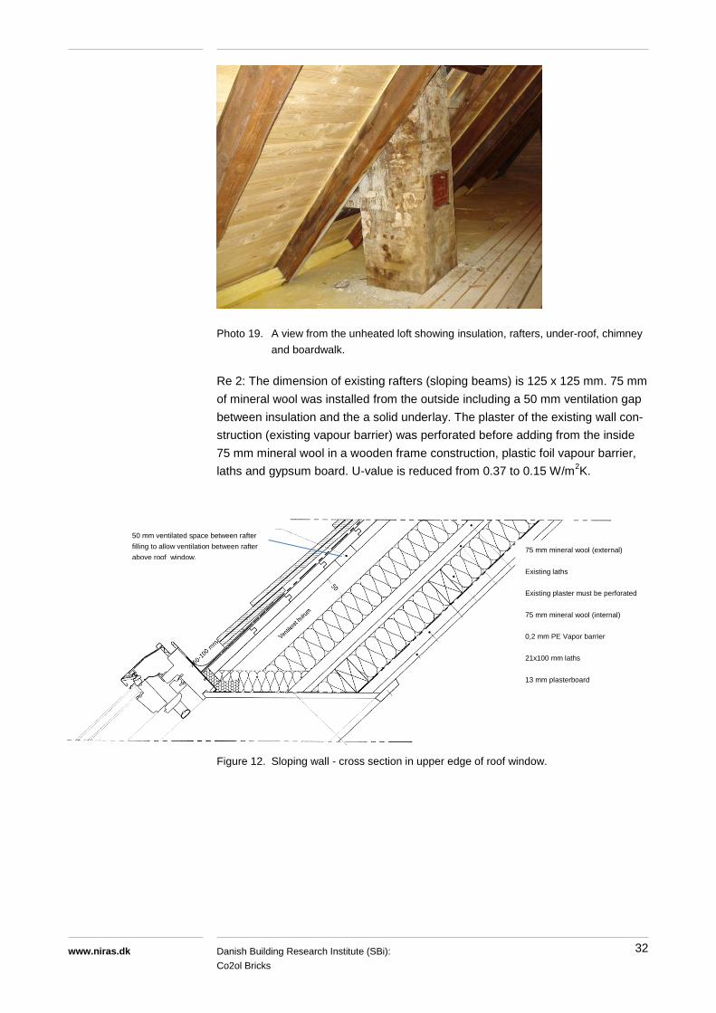
Photo 19. A view from the unheated loft showing insulation, rafters, under-roof, chimney
and boardwalk.
Re 2: The dimension of existing rafters (sloping beams) is 125 x 125 mm. 75 mm
of mineral wool was installed from the outside including a 50 mm ventilation gap
between insulation and the a solid underlay. The plaster of the existing wall con-
struction (existing vapour barrier) was perforated before adding from the inside
75 mm mineral wool in a wooden frame construction, plastic foil vapour barrier,
laths and gypsum board. U-value is reduced from 0.37 to 0.15 W/m2K.
Figure 12. Sloping wall - cross section in upper edge of roof window.
50 mm ventilated space between rafter
filling to allow ventilation between rafter
above roof window.
75 mm mineral wool (external)
Existing laths
Existing plaster must be perforated
75 mm mineral wool (internal)
0,2 mm PE Vapor barrier
21x100 mm laths
13 mm plasterboard

33 Danish Building Research Institute (SBi):
Co2ol Bricks
www.niras.dk
Photo 20. Roof before improved thermal insulation.
Re 3: The sloping wall insulation was also carried out in the space under the
sloping wall to create a warm space. The advantages are less heat loss from
heating pipes, less risk of piping frost burst, better possibility of storing things
without moisture related damage, and the space could easily be converted into a
more useful area. Extra insulation was applied by removing the existing insula-
tion in the vertical wall and installing 100 mm mineral wool. 300 mm of insulation
was placed on the floor, and 200 mm injected into the hollow floor construction
below (see Figure 13).
Figure 13. Space under the sloping wall.

34 Danish Building Research Institute (SBi):
Co2ol Bricks
www.niras.dk
6.2.7 Horizontal partition above depot
The depot is unheated. The collar beam floor construction towards the first floor
was insulated by blowing loose-fill mineral wool fibre insulation into the 200 mm
cavity between the timber beams. U-value was reduced from 1.2 to 0.20 W/m2K.

35 Danish Building Research Institute (SBi):
Co2ol Bricks
www.niras.dk
6.3 The Stable building
6.3.1 Attic
The existing attic is unheated. The horizontal insulation, partly trampled down,
consists of a moderate 100 mm of mineral wool placed on the floor boards in one
layer and therefore without displaced joints between the insulation batts. The risk
of air gaps across the insulation layer increases the heat loss. The insulation was
improved by blowing roughly 200 mm loose-fill mineral wool fibre insulation into
the cavity between the timber beams. U-value was reduced from 0.37 to 0.11
W/m2K.
Photo 21. Unheated attic with existing insulation on top of the floor. Thermal insulation
was improved by injecting the hollow floor with loose-fill insulation.

36 Danish Building Research Institute (SBi):
Co2ol Bricks
www.niras.dk
6.3.2 Lighting
The lighting in conference room was improved. The fixtures and halogen bulbs
(46 units) were replaced with energy-efficient products. Detailed calculations of
electricity savings were made:
Existing lighting system: 6 029 kWh/year or 43.9 kWh/m2 year
New system without daylight regulation: 2 809 kWh/year or 20.4 kWh/m2 year
New system with continuous daylight regulation: 1 869 kWh/ year or 13.6
kWh/m2 year
Because of too high investment costs for implementing daylight regulation the
new lighting system without daylight regulation was implemented. An electricity
reduction of more than 50% is expected.
Figure 14. Calculated illuminance in Lux in the conference room on a horizontal surface
at a height of 0.85 m.
In order to reduce the operating time of the lighting, PIR sensors were estab-
lished on the toilets.

37 Danish Building Research Institute (SBi):
Co2ol Bricks
www.niras.dk
6.4 Estimated energy savings and investments
Early 2010 the consulting company NIRAS made an initial evaluation of possible
energy saving measures. Energy savings were calculated/estimated with simple
but probable methods without performing complete building simulations. Energy
savings for building envelope constructions were calculated based on change in
U-values (transmission heat loss) and heat degree hours. In order to evaluate
whether the different measures were profitable a simple payback time and the
net present value were calculated.
The costs of refurbishment were split into four in order to compare with normal
refurbishment:
I: Total costs of implementing the energy saving measures including all costs
for refurbishment work, set-up, running and supervision at the building site,
scaffolding, planning work, unforeseen costs etc.
F: Costs for e.g. building site, scaffolding, supervision and unforeseen costs.
V: Costs for normal maintenance without focus on energy savings.
M: Extra costs for the actual energy saving measure, e.g. insulation material or
energy efficient glass for windows.
The correlation between the four cost specifications is shown below:
I = F + V + M
Traditional refurbishment = F + V
The profitability of energy saving measures was evaluated from:
PBT: Pay Back Time in years.
NPV: Net Present Value based on SLKE’s profitability formulae. A measure is
profitable if NPV is positive.
Table 4 shows costs and savings for different refurbishment measures. Estimat-
ed investments are shown as percentage distribution. In Table 5 the calculated
annual energy savings are shown in kWh and DKK and EURO. Table 6 shows
the total cost of the refurbishment of Kavalergården and, as a part of this, the
extra cost specifically assigned to the improved energy efficiency of the build-
ings.

38
Danish Building Research Institute (SBi):
Co2ol Bricks www.niras.dk
Table 4. Considered and implemented energy saving measures, investments and profitability. Yellow highlighting: Extra energy saving measures that was not ap-
pointed in the initial screening but implemented anyway as a part of the refurbishment. Pink highlighting: Energy saving measures that was appointed in the
initial screening but not implemented.
Renovation measure
Heat Electr.Life
timeBefore After Heat Electricity
I, Total
investment
F, Building
site etc.
V, Normal
repairM PBT
Positive
NPV
Years % % % % Years Yes/No
Kavaler building
A. Ceiling against attic. Add 200 mm mineral w ool 40 0.19 0.09 1 196 0 100 42 56 2 38 No
B. Sloped w alls. Add 50 mm mineral w ool 40 0.17 0.14 837 0 100 41 57 1 52 No
C. Single layer w indow s in end w all. Add storm w indow s x 20 5.00 1.80 4 590 0 100 27 8 65 8 Yes
D. Window s in facades. Low -e coated glass in storm w indow s x 20 2.80 1.80 5 057 0 100 5 14 81 11 Yes
E. New sky lights x 20 3.00 1.30 3 379 0 100 27 66 8 10 Yes
F. New outer doors x 20 3.50 1.50 2 060 0 100 26 71 4 2 Yes
H. Ceiling in garage. Add 150 mm insulation x 40 0.85 0.15 6 325 0 100 15 42 42 6 Yes
I. Lighting. Energy saving bulbs x 10 40.00 13.00 0 2 444 100 15 0 85 4 Yes
J. Deck in space under the sloped roof. Add 200 mm insulation (granules) x 3 900 0
Infermeri building
A. Floor in attic. Add 200 mm mineral w ool x 40 0.37 0.11 3 175 0 100 27 0 73 14 Yes
B. Sloped w alls. Add 150 mm mineral w ool x 40 0.37 0.15 2 987 0 100 21 59 20 12 YesC. External w alls in ground floor. Internal insulation w ith 100 mm calcium
silicate 40 2.00 0.50 9 332 0 100 27 0 73 16 Yes
D. Single layer w indow s in staircase. Add internal low -e storm w indow s x 20 5.00 1.80 2 169 0 100 27 8 65 7 Yes
E. Window s in facades. Low -e glass in storm w indow s x 20 2.80 1.80 4 267 0 100 5 14 81 13 Yes
F. New sky lights x 20 3.00 1.30 1 229 0 100 27 66 8 10 Yes
G. New outer doors x 20 3.50 1.50 3 543 0 100 27 70 4 2 Yes
I. Lighting i ground floor rooms. Low -e light bulbs 10 0 0 0 2 149 100 27 29 44 0.2 Yes
K. Blocked gate. Add 200 mm mineral w ool, external x 40 2.50 0.19 1 900 0
L. External w alls in depot. Add 200 mm mineral w ool, external x 40 2.50 0.19 4 700 0
M. Deck in space under the sloped roof. 200 mm granules plus 300 mm on the f loorx 2 000 0
N. Roof. Add 20 mm mineral w ool betw een rafters x 150 0
Stable building
A. Floor in attic. Add 200 mm mineral w ool (granules) in deck x 40 0.38 0.10 4 142 0 100 15 0 85 12 Yes
D. Halogen lamps i conference room replaced w ith low -e lamps x 10 70.00 23.00 0 4 390 100 15 0 85 3 Yes
E. Lighting in hall. Adjustment of daylight controll x 20 15.00 15.00 0 225 100 15 0 85 0.5 Yes
F. PIR-sensors on toilets x 0 135
Total energy savings, IMPLEMENTED 66 938 7 194
Extra cost, energy
measures
kWh/year
Measure
implemented
Property, U-
value, Power
W/m2K, W
Energy savings Investments

39
Danish Building Research Institute (SBi):
Co2ol Bricks
www.niras.dk
Table 5. Calculated energy savings estimated in initial investigation. Energy prices of
June 2012
kWh/year DKK/year EUR/year
Total energy savings, heat 57 000 37 000 5 000
Total energy savings, electricity 7 200 14 400 1 900
Total energy savings: approximately 52 000 6 000
Table 6. Costs of refurbishment
DKK EUR
Total refurbishment budget 8 197 000 971 000
Hereof budget for extra costs for improved energy efficiency 865 000 102 000
It is seen from table 5 and 6, that the expected simple PB for the energy upgrade
measures equals almost 17 years, which is still within the expected life time of
the majority of energy saving measures.

40
Danish Building Research Institute (SBi):
Co2ol Bricks
www.niras.dk
7 VALIDATION OF CALCULATED ENERGY USE
From 2009/2010 until 2010/2011, when the energy upgrade was carried out, the
space heating consumption was approximately the same as in the period 2003 to
2008 before the refurbishment. From 2010/2011 to 2011/2012 the space heat
consumption decreases form 146 to 126 kWh/m2 corresponding to a total of
35 600 kWh/year. This could indicate the effect of the energy upgrade, but this
must be verified by measuring the energy consumption in the years to come.
Table 7. Energy consumption for space heating before and after refurbishment
Space heating
[kWh/m2*year]
Total space heating savings
[kWh/year]
Before refurbishment and energy upgrade
146 -
After refurbishment and energy upgrade
126 -
Energy saving measured - 35 600
Expected energy saving - 57 000
The expected space heat savings achieved by the energy upgrade and refur-
bishment were estimated to a total of 57 000 kWh/year equal to approximately
22 % of the space heat consumption. Measurements of the heat consumption
before and approximately one year after the energy upgrade and refurbishment
shows a decrease of 35 600 kWh/year equal to approximately 14 % or only 62 %
of the expected heat savings.
The difference between the expected and the measured savings might be ex-
plained by the short period of measurements after the refurbishment is not rep-
resentative for the future, a different use of the buildings or maybe higher indoor
temperatures etc.

41
Danish Building Research Institute (SBi):
Co2ol Bricks
www.niras.dk
Figure 15. Energy consumption for space heating.

42
Danish Building Research Institute (SBi):
Co2ol Bricks
www.niras.dk
8 REFERENCES
[1] Ruisinger, Ulrich et. al. Institut für Bauklimatik. Energitiche Bewer-
tung von Gebäuden mit raumseitiger Wärmedämmung aus Calciumsil-
ikat. March 2010. http://www.calsitherm.de/
[2] Homepage of Bernstorff Palace. http://www.bernstorffslot.dk/
[3] Measurements of natural gas consumption. Readings by Agency for
Palaces and Cultural Properties, 1999 – 2011.
[4] Homepage of Heritage Agency and division of listed buildings.
http://www.kulturarv.dk/fredede-bygninger/