Embed Size (px)
Citation preview
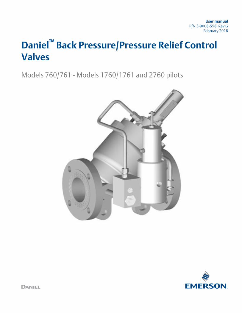
User manualP/N 3-9008-558, Rev G
February 2018
Daniel™ Back Pressure/Pressure Relief ControlValves
Models 760/761 - Models 1760/1761 and 2760 pilots
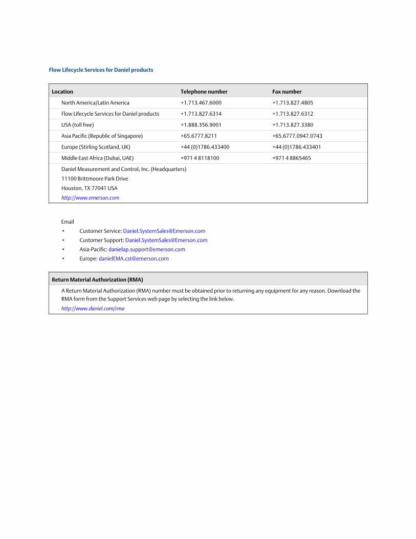
Flow Lifecycle Services for Daniel products
Location Telephone number Fax number
North America/Latin America +1.713.467.6000 +1.713.827.4805
Flow Lifecycle Services for Daniel products +1.713.827.6314 +1.713.827.6312
USA (toll free) +1.888.356.9001 +1.713.827.3380
Asia Pacific (Republic of Singapore) +65.6777.8211 +65.6777.0947.0743
Europe (Stirling Scotland, UK) +44 (0)1786.433400 +44 (0)1786.433401
Middle East Africa (Dubai, UAE) +971 4 8118100 +971 4 8865465
Daniel Measurement and Control, Inc. (Headquarters)
11100 Brittmoore Park Drive
Houston, TX 77041 USA
http://www.emerson.com
• Customer Service: [email protected]
• Customer Support: [email protected]
• Asia-Pacific: [email protected]
• Europe: [email protected]
Return Material Authorization (RMA)
A Return Material Authorization (RMA) number must be obtained prior to returning any equipment for any reason. Download the
RMA form from the Support Services web page by selecting the link below.
http://www.daniel.com/rma
Signal words and symbols
Pay special attention to the following signal words, safety alert symbols and statements:
Safety alert symbol
This is a safety alert symbol. It is used to alert you to potential physical injury hazards. Obey all safety messages that follow this symbol
to avoid possible injury or death.
DANGER!Danger indicates a hazardous situation which, if not avoided, will result in death or serious injury.
WARNING!Warning indicates a hazardous situation which, if not avoided, could result in death or serious injury.
CAUTION!Caution indicates a hazardous situation which, if not avoided, could result in minor or moderate injury.
NOTICENotice is used to address safety messages or practices not related to personal injury.
ImportantImportant is a statement the user needs to know and consider.
TipTip provides information or suggestions for improved efficiency or best results.
NoteNote is “general by-the-way” content not essential to the main flow of information.
Important safety instructions
Daniel Measurement and Control, Inc. (Daniel) designs, manufactures and tests products to function within specific conditions.Because these products are sophisticated technical instruments, it is important that the owner and operation personnel muststrictly adhere both to the information printed on the product and to all instructions provided in this manual prior to installation,operation, and maintenance.
Daniel also urges you to integrate this manual into your training and safety program.
BE SURE ALL PERSONNEL READ AND FOLLOW THE INSTRUCTIONS IN THIS MANUAL AND ALL NOTICES AND PRODUCT WARNINGS.
WARNING!Failure to follow the installation, operation or maintenance instructions for a Daniel product could lead to serious injury or deathfrom explosion or exposure to dangerous substances.
To reduce the risk:
• Comply with all information on the product, in this manual, and in any local and national codes that apply to this product.
• Do not allow untrained personnel to work with this product.
• Use Daniel parts and work procedures specified in this manual.
Product owners (Purchasers):
• Use the correct product for the environment and pressures present. See technical data or product specifications forlimitations. If you are unsure, discuss your needs with your Daniel representative.
• Inform and train all personnel in the proper installation, operation, and maintenance of this product.
• To ensure safe and proper performance, only informed and trained personnel should install, operate, repair and maintainthis product.
• Verify that this is the correct instruction manual for your Daniel product. If this is not the correct documentation, contactDaniel at 1-713-827-6314. You may also download the correct manual from: https://www.emerson.com/en-us/catalog/supervisory-control-systems.
• Save this instruction manual for future reference.
• If you resell or transfer this product, it is your responsibility to forward this instruction manual along with the product to thenew owner or transferee.
• ALWAYS READ AND FOLLOW THE INSTALLATION, OPERATIONS, MAINTENANCE AND TROUBLESHOOTING MANUAL(S) ANDALL PRODUCT WARNINGS AND INSTRUCTIONS.
• Do not use this equipment for any purpose other than its intended service. This may result in property damage and/orserious personal injury or death.
Product operation (Personnel):
• To prevent personal injury, personnel must follow all instructions of this manual prior to and during operation of theproduct.
• Follow all warnings, cautions, and notices marked on, and supplied with, this product.
• Verify that this is the correct instruction manual for your Daniel product. If this is not the correct documentation, contactDaniel at 1-713-827-6314. You may also download the correct manual from: http://www.daniel.com/.
• Read and understand all instructions and operating procedures for this product.
• If you do not understand an instruction, or do not feel comfortable following the instructions, contact your Danielrepresentative for clarification or assistance.
• Install this product as specified in the INSTALLATION section of this manual per applicable local and national codes.
• Follow all instructions during the installation, operation, and maintenance of this product.
• Ensure that all connections to pressure and electrical sources are secure prior to and during equipment operation.
• Use only replacement parts specified by Daniel. Unauthorized parts and procedures can affect this product's performance,safety, and invalidate the warranty. “Look-a-like” substitutions may result in deadly fire, explosion, release of toxicsubstances or improper operation.
• Save this instruction manual for future reference.
Notice
THE CONTENTS OF THIS PUBLICATION ARE PRESENTED FOR INFORMATIONAL PURPOSES ONLY, AND WHILE EVERY EFFORT HASBEEN MADE TO ENSURE THEIR ACCURACY, THEY ARE NOT TO BE CONSTRUED AS WARRANTIES OR GUARANTEES, EXPRESSED ORIMPLIED, REGARDING THE PRODUCTS OR SERVICES DESCRIBED HEREIN OR THEIR USE OR APPLICABILITY. ALL SALES ARE GOVERNEDBY DANIEL'S TERMS AND CONDITIONS, WHICH ARE AVAILABLE UPON REQUEST. WE RESERVE THE RIGHT TO MODIFY OR IMPROVETHE DESIGNS OR SPECIFICATIONS OF SUCH PRODUCTS AT ANY TIME.
DANIEL DOES NOT ASSUME RESPONSIBILITY FOR THE SELECTION, USE OR MAINTENANCE OF ANY PRODUCT. RESPONSIBILITY FORPROPER SELECTION, USE AND MAINTENANCE OF ANY DANIEL PRODUCT REMAINS SOLELY WITH THE PURCHASER AND END-USER.
TO THE BEST OF DANIEL'S KNOWLEDGE THE INFORMATION HEREIN IS COMPLETE AND ACCURATE. DANIEL MAKES NOWARRANTIES, EXPRESSED OR IMPLIED, INCLUDING THE IMPLIED WARRANTIES OF MERCHANTABILITY AND FITNESS FOR APARTICULAR PURPOSE WITH RESPECT TO THIS MANUAL AND, IN NO EVENT, SHALL DANIEL BE LIABLE FOR ANY INCIDENTAL,PUNITIVE, SPECIAL OR CONSEQUENTIAL DAMAGES INCLUDING, BUT NOT LIMITED TO, LOSS OF PRODUCTION, LOSS OF PROFITS,LOSS OF REVENUE OR USE AND COSTS INCURRED INCLUDING WITHOUT LIMITATION FOR CAPITAL, FUEL AND POWER, AND CLAIMSOF THIRD PARTIES.
PRODUCT NAMES USED HEREIN ARE FOR MANUFACTURER OR SUPPLIER IDENTIFICATION ONLY AND MAY BE TRADEMARKS/REGISTERED TRADEMARKS OF THESE COMPANIES.
Warranty and Limitations
1. LIMITED WARRANTY: Subject to the limitations contained in Section 2 herein, Daniel Measurement & Control, Inc. (“Daniel”)warrants that the licensed firmware embodied in the Goods will execute the programming instructions provided by Daniel, and thatthe Goods manufactured by Daniel will be free from defects in materials or workmanship under normal use and care and Serviceswill be performed by trained personnel using proper equipment and instrumentation for the particular Service provided. Theforegoing warranties will apply until the expiration of the applicable warranty period. Goods are warranted for twelve (12) monthsfrom the date of initial installation or eighteen (18) months from the date of shipment by Daniel, whichever period expires first.Consumables and Services are warranted for a period of 90 days from the date of shipment or completion of the Services. Productspurchased by Daniel from a third party for resale to Buyer (“Resale Products”) shall carry only the warranty extended by the originalmanufacturer. Buyer agrees that Daniel has no liability for Resale Products beyond making a reasonable commercial effort toarrange for procurement and shipping of the Resale Products. If Buyer discovers any warranty defects and notifies Daniel thereof inwriting during the applicable warranty period, Daniel shall, at its option, correct any errors that are found by Daniel in the firmwareor Services or repair or replace F.O.B. point of manufacture that portion of the Goods or firmware found by Daniel to be defective, orrefund the purchase price of the defective portion of the Goods/Services. All replacements or repairs necessitated by inadequatemaintenance, normal wear and usage, unsuitable power sources or environmental conditions, accident, misuse, improperinstallation, modification, repair, use of unauthorized replacement parts, storage or handling, or any other cause not the fault ofDaniel are not covered by this limited warranty, and shall be at Buyer's expense. Daniel shall not be obligated to pay any costs orcharges incurred by Buyer or any other party except as may be agreed upon in writing in advance by Daniel. All costs of dismantling,reinstallation and freight and the time and expenses of Daniel's personnel and representatives for site travel and diagnosis underthis warranty clause shall be borne by Buyer unless accepted in writing by Daniel. Goods repaired and parts replaced by Danielduring the warranty period shall be in warranty for the remainder of the original warranty period or ninety (90) days, whichever islonger. This limited warranty is the only warranty made by Daniel and can be amended only in a writing signed by Daniel. THEWARRANTIES AND REMEDIES SET FORTH ABOVE ARE EXCLUSIVE. THERE ARE NO REPRESENTATIONS OR WARRANTIES OF ANYKIND, EXPRESS OR IMPLIED, AS TO MERCHANTABILITY, FITNESS FOR PARTICULAR PURPOSE OR ANY OTHER MATTER WITH RESPECTTO ANY OF THE GOODS OR SERVICES. Buyer acknowledges and agrees that corrosion or erosion of materials is not covered by thiswarranty.
2. LIMITATION OF REMEDY AND LIABILITY: Daniel shall not be liable for damages caused by delay in performance. The remedies ofBuyer set forth in this agreement are exclusive. In no event, regardless of the form of the claim or cause of action (whether based incontract, infringement, negligence, strict liability, other tort or otherwise), shall Daniel's liability to Buyer and/or its customersexceed the price to Buyer of the specific goods manufactured or services provided by Daniel giving rise to the claim or cause ofaction. Buyer agrees that in no event shall Daniel's liability to Buyer and/or its customers extend to include incidental, consequentialor punitive damages. The term “consequential damages” shall include, but not be limited to, loss of anticipated profits, revenue oruse and costs incurred including without limitation for capital, fuel and power, and claims of Buyer's customers.

Contents
Part I PlanChapter 1 Introduction ..................................................................................................................3
1.1 Purpose of this manual ................................................................................................................31.2 Description of the Models 760 and 761 Control Valves ............................................................... 3
1.2.1 Control valve general features ......................................................................................31.2.2 Operation overview of the control valve ....................................................................... 31.2.3 Parts lists for the back pressure/Pressure relief control valve ........................................ 8
1.3 Agency certifications for the Models 760 and 761 Control Valves ............................................. 29
Chapter 2 Operating conditions and specifications ...................................................................... 312.1 Operating conditions for the Model 760 and 761 ......................................................................31
2.1.1 Design considerations ................................................................................................ 322.1.2 Environmental conditions .......................................................................................... 33
2.2 Description of the Models 760 and 761 Control Valves ............................................................. 342.2.1 Interface requirements ...............................................................................................342.2.2 Requirements and limitations for installation ............................................................. 352.2.3 Minimum clearances for installation, operation and maintenance ..............................36
2.3 Pilot spring selection .................................................................................................................382.3.1 Pilot spring selection table ......................................................................................... 382.3.2 Table usage ................................................................................................................ 40
Part II InstallChapter 3 Installation prerequisites .............................................................................................43
3.1 Models 760 and 761 pre-start checks ........................................................................................433.2 Model 760 and 761 installation .................................................................................................44
Part III OperateChapter 4 Operation start up .......................................................................................................49
4.1 Model 760 adjustment and startup ........................................................................................... 494.2 Model 761 adjustment and startup ........................................................................................... 50
Part IV MaintainChapter 5 Planned maintenance ..................................................................................................55
5.1 Maintenance considerations ..................................................................................................... 555.2 Pilot disassembly (1760/1761) ..................................................................................................565.3 Pilot disassembly (2760) .......................................................................................................... 575.4 Pilot assembly (760/761) .......................................................................................................... 58
Chapter 6 Spare parts .................................................................................................................. 59
Contents
User manual i
6.1 Recommended spare parts ....................................................................................................... 596.2 Order spare parts ...................................................................................................................... 59
Appendices and referenceAppendix A Combination needle valve and strainer ........................................................................61
A.1 Disassembly and assembly ....................................................................................................... 61A.2 Needle valve and strainer combination ..................................................................................... 62A.3 Order spare parts ...................................................................................................................... 64
Appendix B Relief valve pilot bypass ...............................................................................................65B.1 Introduction ............................................................................................................................. 65B.2 Operation ................................................................................................................................. 66B.3 Primary pilot valve .................................................................................................................... 66B.4 Secondary pilot valve ................................................................................................................ 66B.5 Pilot control set points .............................................................................................................. 66B.6 Installation ................................................................................................................................66B.7 Adjustments ............................................................................................................................. 67B.8 Needle valves ............................................................................................................................67B.9 Micro Switch ............................................................................................................................. 68B.10 Pilot line block valves ................................................................................................................ 68
Appendix C Testing Daniel Model 1760/1761 or 2760 Relief valve pilot set point in the field ........... 71C.1 Testing models 1760/1761 or 2760 .......................................................................................... 71
Contents
ii Daniel Back Pressure/Pressure Relief Control Valves
Part IPlan
Chapters covered in this part:
• Introduction
• Operating conditions and specifications
Plan
User manual 1
Plan
2 Daniel Back Pressure/Pressure Relief Control Valves
1 IntroductionTopics covered in this chapter:
• Purpose of this manual
• Description of the Models 760 and 761 Control Valves
• Agency certifications for the Models 760 and 761 Control Valves
1.1 Purpose of this manualThis manual provides guidance to owners and personnel in the installation, operation andmaintenance of the DanielTM Back Pressure/Pressure Relief Control Valves 760 and 761 andModels 1760/1761 and 2760 Pilots manual, 3-9008-558. It is imperative that product ownersand operation personnel read and follow the information contained in this manual toensure that the control valve is installed correctly and is operating according to the designcertifications and safety considerations.
NOTICE
Use this manual along with the Series 700B Control Valves manual.
1.2 Description of the Models 760 and 761 ControlValves
1.2.1 Control valve general featuresDaniel™ Model 760 and 761 Control Valves are designed to maintain a specific minimumupstream pressure regardless of fluctuations in flow rate or downstream pressure. Whencorrectly installed and adjusted, these valves will maintain upstream pressure at a valuewithin 13.79 kPa (2 psi) of the valve pilot's setting. A minimum pressure differential acrossthe valve of 69 kPa (10 psi) is required for it to fully open.
1.2.2 Operation overview of the control valveThe Models 760 and 761 Daniel™ Control Valves are designed to regulate back pressurewithin +/- 13.8 kPa (2 psi) or closer, regardless of the variations in flow rate or downstreampressure. The pilots are balanced, single seated valves with large ports and are not affectedby variations in downstream pressure.
Introduction
User manual 3
The Models 760 and 761 operate on a balanced-piston principle. When pressures on bothsides of the piston are equalized, a spring located on top of the piston acts as a differentialforce and closes the piston. When the pressure against the bottom of the piston exceedsthe pressure plus the force of the spring exerted against the top of the piston, springtension is overcome, and the valve opens.
It is from this principle of operation that all variations of control with the use of pilot valvesand accessories are made. Back pressure pilots control pressure applied to the spring sideof the main valve piston, acting as a variable orifice, which in turn allows the main valve toregulate upstream pressure.
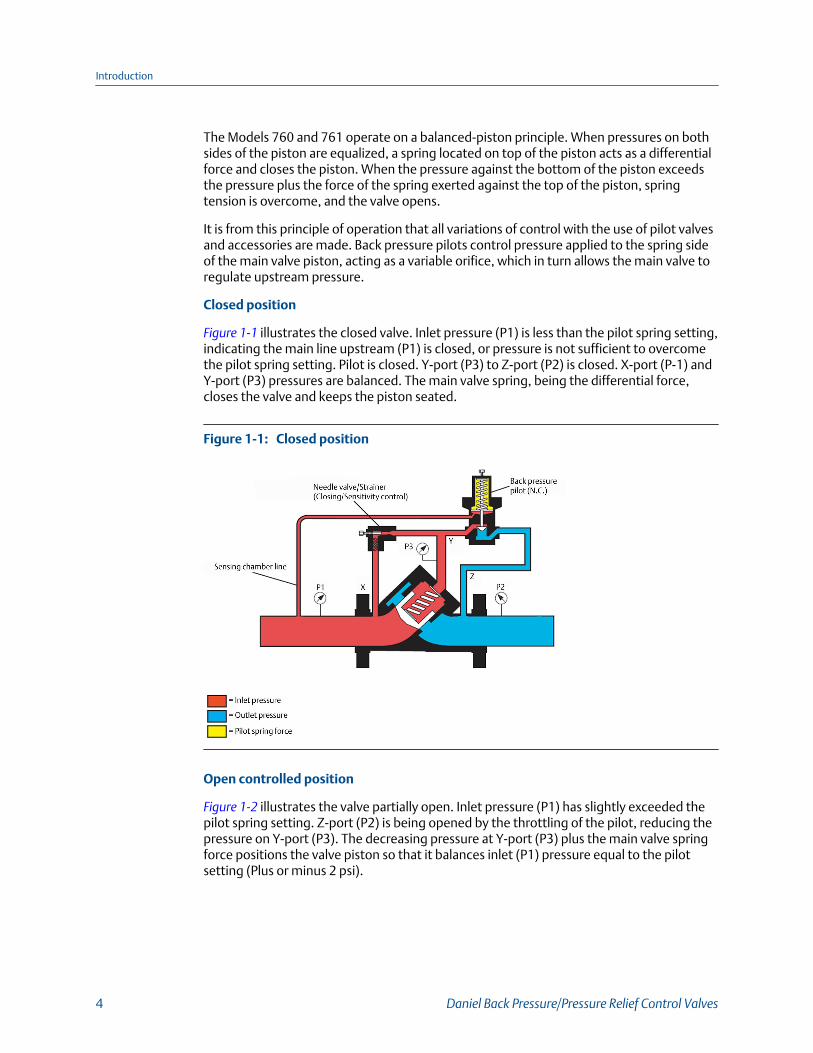
Closed position
Figure 1-1 illustrates the closed valve. Inlet pressure (P1) is less than the pilot spring setting,indicating the main line upstream (P1) is closed, or pressure is not sufficient to overcomethe pilot spring setting. Pilot is closed. Y-port (P3) to Z-port (P2) is closed. X-port (P-1) andY-port (P3) pressures are balanced. The main valve spring, being the differential force,closes the valve and keeps the piston seated.
Closed positionFigure 1-1:
Open controlled position
Figure 1-2 illustrates the valve partially open. Inlet pressure (P1) has slightly exceeded thepilot spring setting. Z-port (P2) is being opened by the throttling of the pilot, reducing thepressure on Y-port (P3). The decreasing pressure at Y-port (P3) plus the main valve springforce positions the valve piston so that it balances inlet (P1) pressure equal to the pilotsetting (Plus or minus 2 psi).
Introduction
4 Daniel Back Pressure/Pressure Relief Control Valves
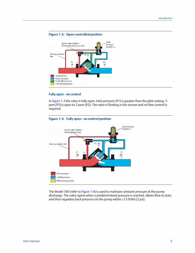
Open controlled positionFigure 1-2:
Fully open - no control
In Figure 1-3 the valve is fully open. Inlet pressure (P1) is greater than the pilot setting. Y-port (P3) is open to Z-port (P2). The valve is floating in the stream and no flow control isrequired.
Fully open - no control positionFigure 1-3:
The Model 760 (refer to Figure 1-4) is used to maintain constant pressure at the pumpdischarge. The valve opens when a predetermined pressure is reached, allows flow to start,and then regulates back pressure on the pump within ±13.8 kPa (2 psi).
Introduction
User manual 5
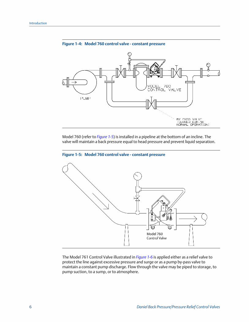
Model 760 control valve - constant pressureFigure 1-4:
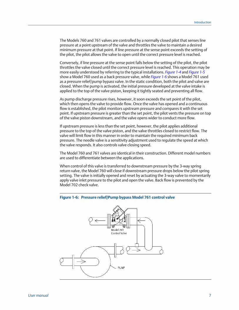
Model 760 (refer to Figure 1-5) is installed in a pipeline at the bottom of an incline. Thevalve will maintain a back pressure equal to head pressure and prevent liquid separation.
Model 760 control valve - constant pressureFigure 1-5:
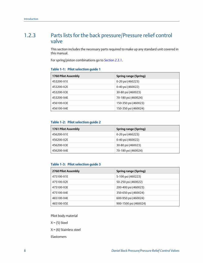
The Model 761 Control Valve illustrated in Figure 1-6 is applied either as a relief valve toprotect the line against excessive pressure and surge or as a pump by-pass valve tomaintain a constant pump discharge. Flow through the valve may be piped to storage, topump suction, to a sump, or to atmosphere.
Introduction
6 Daniel Back Pressure/Pressure Relief Control Valves
The Models 760 and 761 valves are controlled by a normally closed pilot that senses linepressure at a point upstream of the valve and throttles the valve to maintain a desiredminimum pressure at that point. If line pressure at the sense point exceeds the setting ofthe pilot, the pilot allows the valve to open until the correct pressure level is reached.
Conversely, if line pressure at the sense point falls below the setting of the pilot, the pilotthrottles the valve closed until the correct pressure level is reached. This operation may bemore easily understood by referring to the typical installations. Figure 1-4 and Figure 1-5show a Model 760 used as a back pressure valve, while Figure 1-6 shows a Model 761 usedas a pressure relief/pump bypass valve. In the static condition, both the pilot and valve areclosed. When the pump is activated, the initial pressure developed at the valve intake isapplied to the top of the valve piston, keeping it tightly seated and preventing all flow.
As pump discharge pressure rises, however, it soon exceeds the set point of the pilot,which then opens the valve to provide flow. Once the valve has opened and a continuousflow is established, the pilot monitors upstream pressure and compares it with the setpoint. If upstream pressure is greater than the set point, the pilot vents the pressure on topof the valve piston downstream, and the valve opens wider to conduct more flow.
If upstream pressure is less than the set point, however, the pilot applies additionalpressure to the top of the valve piston, and the valve throttles closed to restrict flow. Thevalve will limit flow in this manner in order to maintain the required minimum backpressure. The needle valve is a sensitivity adjustment used to regulate the speed at whichthe valve responds. It also controls valve closing speed.
The Model 760 and 761 valves are identical in their construction. Different model numbersare used to differentiate between the applications.
When control of this valve is transferred to downstream pressure by the 3-way springreturn valve, the Model 760 will close if downstream pressure drops below the pilot springsetting. The valve is initially opened and reset by actuating the 3-way valve to momentarilyapply valve inlet pressure to the pilot and open the valve. Back flow is prevented by theModel 702 check valve.
Pressure relief/Pump bypass Model 761 control valveFigure 1-6:
Introduction
User manual 7
1.2.3 Parts lists for the back pressure/Pressure relief controlvalveThis section includes the necessary parts required to make up any standard unit covered inthis manual.
For spring/piston combinations go to Section 2.3.1.
Pilot selection guide 1Table 1-1:
1760 Pilot Assembly Spring range (Spring)
453200-X1E 0-20 psi (460223)
453200-X2E 0-40 psi (460022)
453200-X3E 30-80 psi (460023)
453200-X4E 70-180 psi (460024)
456100-X3E 150-350 psi (460023)
456100-X4E 150-350 psi (460024)
Pilot selection guide 2Table 1-2:
1761 Pilot Assembly Spring range (Spring)
456200-X1E 0-20 psi (460223)
456200-X2E 0-40 psi (460022)
456200-X3E 30-80 psi (460023)
456200-X4E 70-180 psi (460024)
Pilot selection guide 3Table 1-3:
2760 Pilot Assembly Spring range (Spring)
475100-X1E 5-100 psi (460223)
475100-X2E 50-250 psi (460022)
475100-X3E 200-400 psi (460023)
475100-X4E 350-650 psi (460024)
465100-X4E 600-950 psi (460024)
465100-X5E 900-1500 psi (460024)
Pilot body material
X = (5) Steel
X = (6) Stainless steel
Elastomers
Introduction
8 Daniel Back Pressure/Pressure Relief Control Valves
E = (0) NBR
E = (7) EPR
E = (5) FFKM
E = (4) NBR (Low swell)
E = (3) CR
E = (2) FKM
E = (G) FKM GFLT
E = (M) FKM V1289
E = (9) FKM for LPG Service
ImportantItem numbers reference actual engineering drawings and are not meant to be consecutivelynumbered.
Introduction
User manual 9
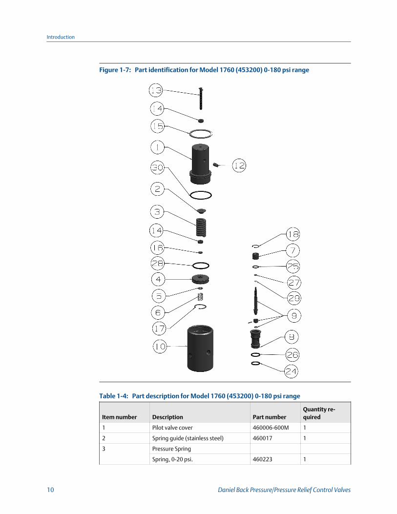
Part identification for Model 1760 (453200) 0-180 psi rangeFigure 1-7:
Part description for Model 1760 (453200) 0-180 psi rangeTable 1-4:
Item number Description Part numberQuantity re-quired
1 Pilot valve cover 460006-600M 1
2 Spring guide (stainless steel) 460017 1
3 Pressure Spring
Spring, 0-20 psi. 460223 1
Introduction
10 Daniel Back Pressure/Pressure Relief Control Valves
Part description for Model 1760 (453200) 0-180 psi range (continued)Table 1-4:
Item number Description Part numberQuantity re-quired
Spring, 0-40 psi. 460022 1
Spring, 30-80 psi. 460023 1
Spring, 70-180 psi. 460024 1
4 Piston 460116 1
5 Thrust washer (stainless steel) 460013 1
6 Damper spring 460021 1
7 Guide bushing 460008 1
8 Pilot valve cage 460007
9 Poppet shaft assembly, NBR 460110-000 1
Poppet shaft assembly, EPR 460110-007 1
Poppet shaft assembly, FFKM 460110-005 1
Poppet shaft assembly, NBR (Low-swell)
460110-00L 1
Poppet shaft assembly, CR 460110-003 1
Poppet shaft assembly, FKM 460110 1
Poppet shaft assembly, FKM GFLT 460110-00G 1
Poppet shaft assembly, FKM V1289 460110-00M 1
10 Pilot body CS 453301-500M 1
Pilot body SS 453301-600M 1
12 Vent plug assembly 460015-500M 1
13 Screw set, square head 150687-024 1
14 Nut, hex 151543-019 2
15 Retaining ring, internal 156465 1
16 Washer SS lock, spring 152267 1
17 Retaining ring, internal 156466 1
18 Retaining ring, internal 156467 1
24 O-ring, NBR 157009 1
O-ring, EPR 157009-005 1
O-ring, FFKM 157009-075 1
O-ring, NBR (Low-swell) 157009-120 1
O-ring, CR 157009-116 1
O-ring, FKM 157009-022 1
O-ring, FKM GFLT 157009-027 1
O-ring, FKM V1289 157009-029 1
25 O-ring, NBR 152090 1
Introduction
User manual 11
Part description for Model 1760 (453200) 0-180 psi range (continued)Table 1-4:
Item number Description Part numberQuantity re-quired
O-ring, EPR 152090-005 1
O-ring, FFKM 152090-075 1
O-ring, NBR (Low-swell) 152090-120 1
O-ring, CR 152090-116 1
O-ring, FKM 152090-022 1
O-ring, FKM GFLT 152090-027 1
O-ring, FKM V1289 152090-029 1
26 O-ring, NBR 157010 1
O-ring, EPR 157010-005 1
O-ring, FFKM 157010-075 1
O-ring, NBR (Low-swell) 157010-120 1
O-ring, CR 157010-116 1
O-ring, FKM 157010-022 1
O-ring, FKM GFLT 157010-027 1
O-ring, FKM V1289 157010-029 1
27 O-ring, NBR 152066 1
O-ring, EPR 152066-005 1
O-ring, FFKM 152066-075 1
O-ring, NBR (Low-swell) 152066-120 1
O-ring, CR 152066-116 1
O-ring, FKM 152066-022 1
O-ring, FKM GFLT 152066-027 1
O-ring, FKM V1289 152066-029 1
28 O-ring, NBR 152073 1
O-ring, EPR 152073-005 1
O-ring, FFKM 152073-075 1
O-ring, NBR (Low-swell) 152073-120 1
O-ring, CR 152073-116 1
O-ring, FKM 152073-022 1
O-ring, FKM GFLT 152073-027 1
O-ring, FKM V1289 152073-029 1
29 O-ring, NBR 152064 1
O-ring, EPR 152064-005 1
O-ring, FFKM 152064-075 1
O-ring, NBR (Low-swell) 152064-120 1
Introduction
12 Daniel Back Pressure/Pressure Relief Control Valves
Part description for Model 1760 (453200) 0-180 psi range (continued)Table 1-4:
Item number Description Part numberQuantity re-quired
O-ring, CR 152064-116 1
O-ring, FKM 152064-022 1
O-ring, FKM GFLT 152064-027 1
O-ring, FKM V1289 152064-029 1
30 O-ring, NBR 157011 1
O-ring, EPR 157011-005 1
O-ring, FFKM 157011-075 1
O-ring, NBR (Low-swell) 157011-125 1
O-ring, CR 157011-116 1
O-ring, FKM 157011-022 1
O-ring, FKM GFLT 157011-027 1
O-ring, FKM V1289 157011-029 1
Introduction
User manual 13
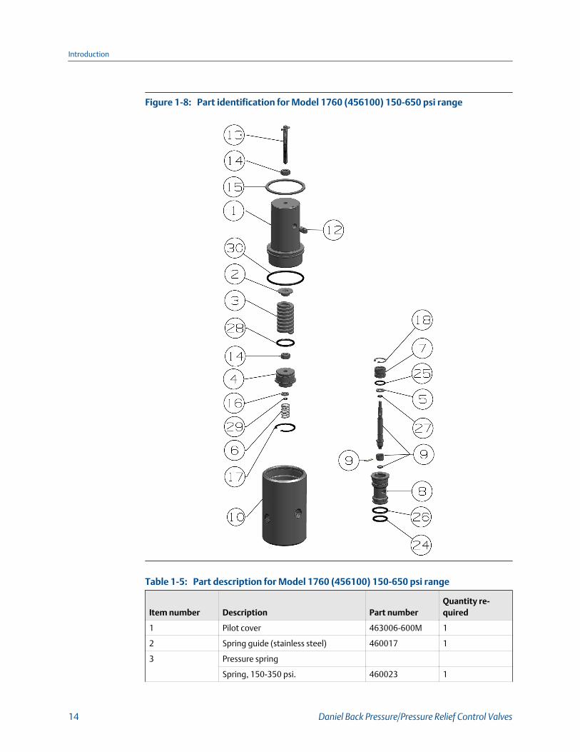
Part identification for Model 1760 (456100) 150-650 psi rangeFigure 1-8:
Part description for Model 1760 (456100) 150-650 psi rangeTable 1-5:
Item number Description Part numberQuantity re-quired
1 Pilot cover 463006-600M 1
2 Spring guide (stainless steel) 460017 1
3 Pressure spring
Spring, 150-350 psi. 460023 1
Introduction
14 Daniel Back Pressure/Pressure Relief Control Valves
Part description for Model 1760 (456100) 150-650 psi range (continued)Table 1-5:
Item number Description Part numberQuantity re-quired
Spring, 350-650 psi. 460024 1
4 Piston (stainless steel) 463016 1
5 Thrust washer (stainless steel) 460013 1
6 Damper spring 460021 1
7 Guide bushing 460008 1
8 Cage pilot valve 460007 1
9 Poppet shaft assembly, NBR 460110-000 1
Poppet shaft assembly, EPR 460110-007 1
Poppet shaft assembly, FFKM 460110-005 1
Poppet shaft assembly, NBR (Low-swell)
460110-00L 1
Poppet shaft assembly, CR 460110-003 1
Poppet shaft assembly, FKM 460110 1
Poppet shaft assembly, FKM GFLT 460110-00G 1
Poppet shaft assembly, FKM V1289 460110-00M 1
10 Pilot body CS 453301-500M 1
Pilot body SS 453301-600M 1
12 Vent plug assembly 460015-500M 1
13 Screw set, square head 150687-024 1
14 Nut, hex 151543-019 2
15 Retaining ring, internal 156465 1
16 Washer SS lock, spring 152267 1
17 Retaining ring, internal 156466 1
18 Retaining ring, internal 156467 1
24 O-ring, NBR 157009 1
O-ring, EPR 157009-005 1
O-ring, FFKM 157009-075 1
O-ring, NBR (Low-swell) 157009-120 1
O-ring, CR 157009-116 1
O-ring, FKM 157009-022 1
O-ring, FKM GFLT 157009-027 1
O-ring, FKM V1289 157009-029 1
25 O-ring, NBR 152090 1
O-ring, EPR 152090-005 1
O-ring, FFKM 152090-075 1
Introduction
User manual 15
Part description for Model 1760 (456100) 150-650 psi range (continued)Table 1-5:
Item number Description Part numberQuantity re-quired
O-ring, NBR (Low-swell) 152090-120 1
O-ring, CR 152090-116 1
O-ring, FKM 152090-022 1
O-ring, FKM GFLT 152090-027 1
O-ring, FKM V1289 152090-029 1
26 O-ring, NBR 157010 1
O-ring, EPR 157010-005 1
O-ring, FFKM 157010-075 1
O-ring, NBR (Low-swell) 157010-120 1
O-ring, CR 157010-116 1
O-ring, FKM 157010-022 1
O-ring, FKM GFLT 157010-027 1
O-ring, FKM V1289 157010-029 1
27 O-ring, NBR 152066 1
O-ring, EPR 152006-005 1
O-ring, FFKM 152006-075 1
O-ring, NBR (Low-swell) 152006-120 1
O-ring, CR 152006-116 1
O-ring, FKM 152006-022 1
O-ring, FKM GFLT 152006-027 1
O-ring, FKM V1289 152006-029 1
28 O-ring, NBR 152091 1
O-ring, EPR 152091-005 1
O-ring, FFKM 152091-075 1
O-ring, NBR (Low-swell) 152091-120 1
O-ring, CR 152091-116 1
O-ring, FKM 152091-022 1
O-ring, FKM GFLT 152091-027 1
O-ring, FKM V1289 152091-029 1
29 O-ring, NBR 152064 1
O-ring, EPR 152064-005 1
O-ring, FFKM 152064-075 1
O-ring, NBR (Low-swell) 152064-120 1
O-ring, CR 152064-116 1
O-ring, FKM 152064-022 1
Introduction
16 Daniel Back Pressure/Pressure Relief Control Valves
Part description for Model 1760 (456100) 150-650 psi range (continued)Table 1-5:
Item number Description Part numberQuantity re-quired
O-ring, FKM GFLT 152064-027 1
O-ring, FKM V1289 152064-029 1
30 O-ring, NBR 157011 1
O-ring, EPR 157011-005 1
O-ring, FFKM 157011-075 1
O-ring, NBR (Low-swell) 157011-120 1
O-ring, CR 157011-116 1
O-ring, FKM 157011-022 1
O-ring, FKM GFLT 157011-027 1
O-ring, FKM V1289 157011-029 1
Introduction
User manual 17

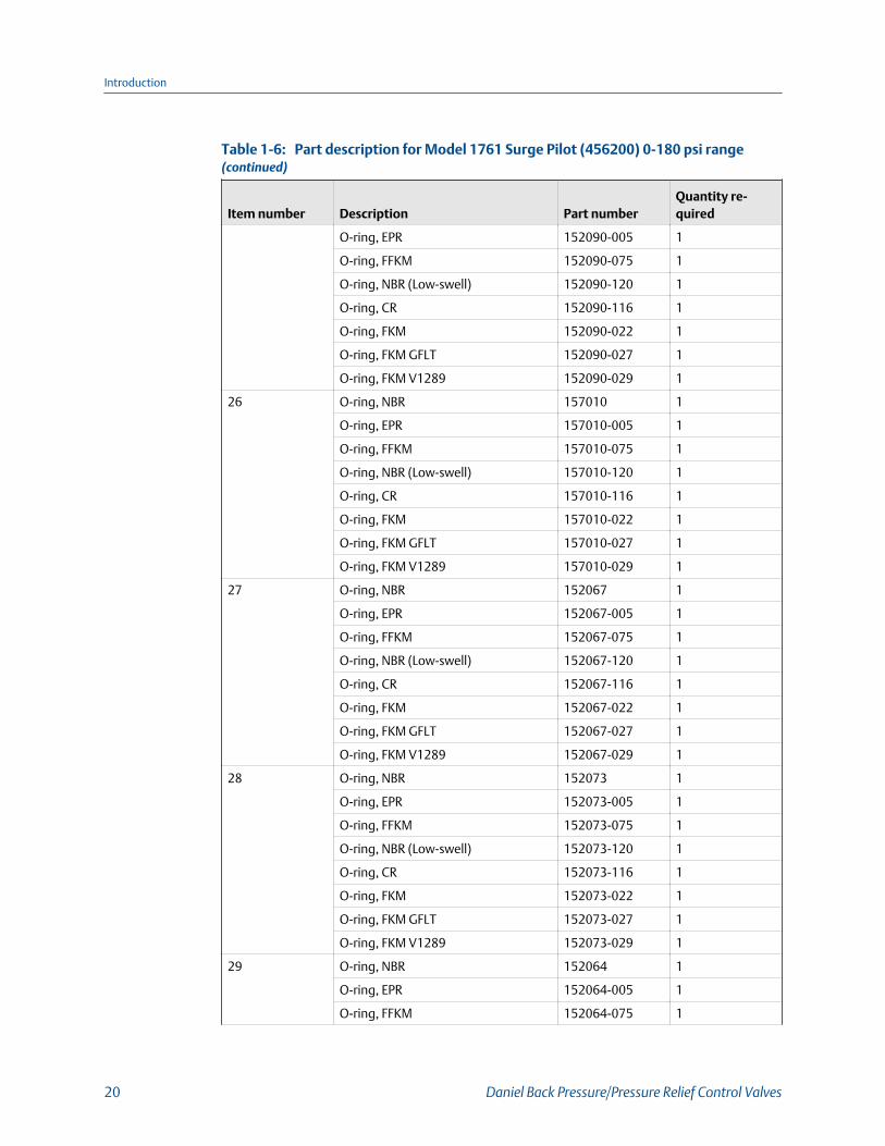
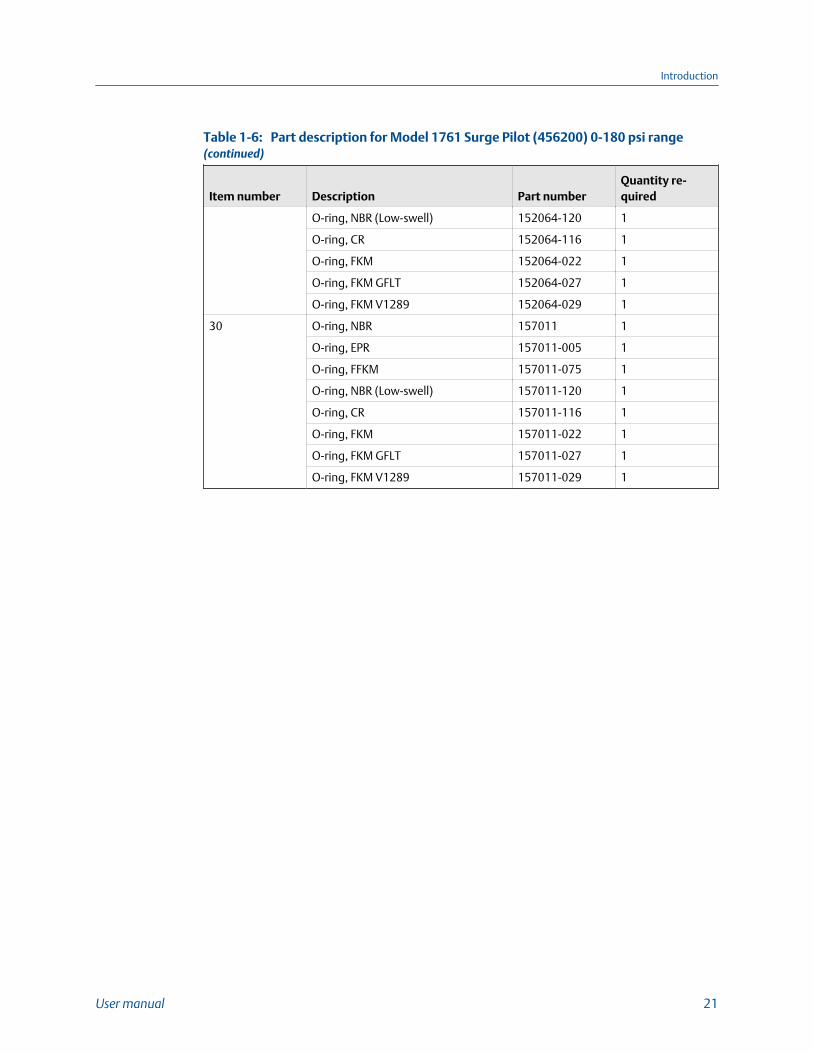
Part identification for Model 1761 Surge Pilot (456200) 0-180 psi rangeFigure 1-9:
Part description for Model 1761 Surge Pilot (456200) 0-180 psi rangeTable 1-6:
Item number Description Part numberQuantity re-quired
1 Pilot cover 460006-600M 1
2 Spring guide (stainless steel) 460017 1
3 Pressure spring, 0-20 lbs. 460223 1
Spring, 0-40 psi. 460022 1
Introduction
18 Daniel Back Pressure/Pressure Relief Control Valves
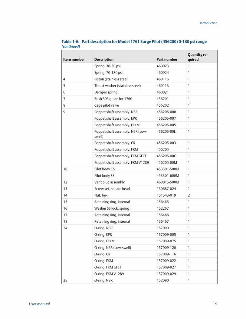
Part description for Model 1761 Surge Pilot (456200) 0-180 psi range(continued)Table 1-6:
Item number Description Part numberQuantity re-quired
Spring, 30-80 psi. 460023 1
Spring, 70-180 psi. 460024 1
4 Piston (stainless steel) 460116 1
5 Thrust washer (stainless steel) 460113 1
6 Damper spring 460021 1
7 Bush 303 guide for 1760 456201 1
8 Cage pilot valve 456202 1
9 Poppet shaft assembly, NBR 456205-000 1
Poppet shaft assembly, EPR 456205-007 1
Poppet shaft assembly, FFKM 456205-005 1
Poppet shaft assembly, NBR (Low-swell)
456205-00L 1
Poppet shaft assembly, CR 456205-003 1
Poppet shaft assembly, FKM 456205 1
Poppet shaft assembly, FKM GFLT 456205-00G 1
Poppet shaft assembly, FKM V1289 456205-00M 1
10 Pilot body CS 453301-500M 1
Pilot body SS 453301-600M 1
12 Vent plug assembly 460015-500M 1
13 Screw set, square head 150687-024 1
14 Nut, hex 151543-019 2
15 Retaining ring, internal 156465 1
16 Washer SS lock, spring 152267 1
17 Retaining ring, internal 156466 1
18 Retaining ring, internal 156467 1
24 O-ring, NBR 157009 1
O-ring, EPR 157009-005 1
O-ring, FFKM 157009-075 1
O-ring, NBR (Low-swell) 157009-120 1
O-ring, CR 157009-116 1
O-ring, FKM 157009-022 1
O-ring, FKM GFLT 157009-027 1
O-ring, FKM V1289 157009-029 1
25 O-ring, NBR 152090 1
Introduction
User manual 19
Part description for Model 1761 Surge Pilot (456200) 0-180 psi range(continued)Table 1-6:
Item number Description Part numberQuantity re-quired
O-ring, EPR 152090-005 1
O-ring, FFKM 152090-075 1
O-ring, NBR (Low-swell) 152090-120 1
O-ring, CR 152090-116 1
O-ring, FKM 152090-022 1
O-ring, FKM GFLT 152090-027 1
O-ring, FKM V1289 152090-029 1
26 O-ring, NBR 157010 1
O-ring, EPR 157010-005 1
O-ring, FFKM 157010-075 1
O-ring, NBR (Low-swell) 157010-120 1
O-ring, CR 157010-116 1
O-ring, FKM 157010-022 1
O-ring, FKM GFLT 157010-027 1
O-ring, FKM V1289 157010-029 1
27 O-ring, NBR 152067 1
O-ring, EPR 152067-005 1
O-ring, FFKM 152067-075 1
O-ring, NBR (Low-swell) 152067-120 1
O-ring, CR 152067-116 1
O-ring, FKM 152067-022 1
O-ring, FKM GFLT 152067-027 1
O-ring, FKM V1289 152067-029 1
28 O-ring, NBR 152073 1
O-ring, EPR 152073-005 1
O-ring, FFKM 152073-075 1
O-ring, NBR (Low-swell) 152073-120 1
O-ring, CR 152073-116 1
O-ring, FKM 152073-022 1
O-ring, FKM GFLT 152073-027 1
O-ring, FKM V1289 152073-029 1
29 O-ring, NBR 152064 1
O-ring, EPR 152064-005 1
O-ring, FFKM 152064-075 1
Introduction
20 Daniel Back Pressure/Pressure Relief Control Valves
Part description for Model 1761 Surge Pilot (456200) 0-180 psi range(continued)Table 1-6:
Item number Description Part numberQuantity re-quired
O-ring, NBR (Low-swell) 152064-120 1
O-ring, CR 152064-116 1
O-ring, FKM 152064-022 1
O-ring, FKM GFLT 152064-027 1
O-ring, FKM V1289 152064-029 1
30 O-ring, NBR 157011 1
O-ring, EPR 157011-005 1
O-ring, FFKM 157011-075 1
O-ring, NBR (Low-swell) 157011-120 1
O-ring, CR 157011-116 1
O-ring, FKM 157011-022 1
O-ring, FKM GFLT 157011-027 1
O-ring, FKM V1289 157011-029 1
Introduction
User manual 21
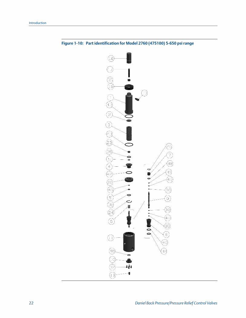
Part identification for Model 2760 (475100) 5-650 psi rangeFigure 1-10:
Introduction
22 Daniel Back Pressure/Pressure Relief Control Valves
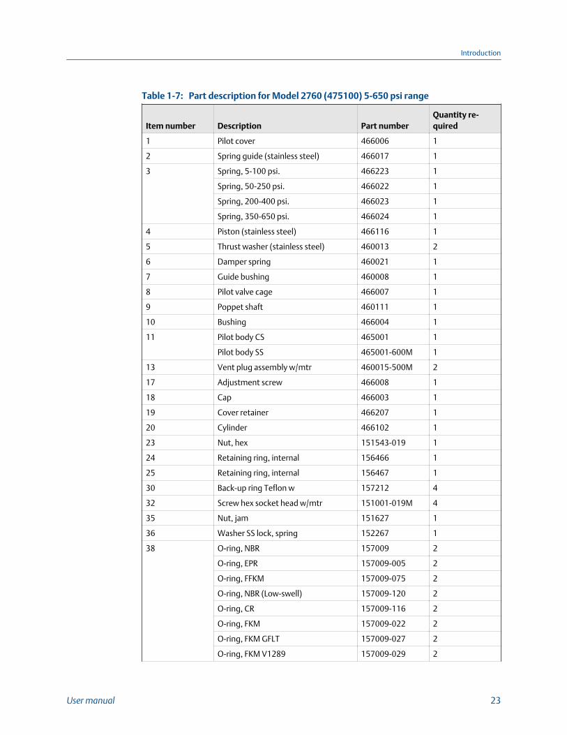
Part description for Model 2760 (475100) 5-650 psi rangeTable 1-7:
Item number Description Part numberQuantity re-quired
1 Pilot cover 466006 1
2 Spring guide (stainless steel) 466017 1
3 Spring, 5-100 psi. 466223 1
Spring, 50-250 psi. 466022 1
Spring, 200-400 psi. 466023 1
Spring, 350-650 psi. 466024 1
4 Piston (stainless steel) 466116 1
5 Thrust washer (stainless steel) 460013 2
6 Damper spring 460021 1
7 Guide bushing 460008 1
8 Pilot valve cage 466007 1
9 Poppet shaft 460111 1
10 Bushing 466004 1
11 Pilot body CS 465001 1
Pilot body SS 465001-600M 1
13 Vent plug assembly w/mtr 460015-500M 2
17 Adjustment screw 466008 1
18 Cap 466003 1
19 Cover retainer 466207 1
20 Cylinder 466102 1
23 Nut, hex 151543-019 1
24 Retaining ring, internal 156466 1
25 Retaining ring, internal 156467 1
30 Back-up ring Teflon w 157212 4
32 Screw hex socket head w/mtr 151001-019M 4
35 Nut, jam 151627 1
36 Washer SS lock, spring 152267 1
38 O-ring, NBR 157009 2
O-ring, EPR 157009-005 2
O-ring, FFKM 157009-075 2
O-ring, NBR (Low-swell) 157009-120 2
O-ring, CR 157009-116 2
O-ring, FKM 157009-022 2
O-ring, FKM GFLT 157009-027 2
O-ring, FKM V1289 157009-029 2
Introduction
User manual 23

Part description for Model 2760 (475100) 5-650 psi range (continued)Table 1-7:
Item number Description Part numberQuantity re-quired
39 O-ring, NBR 152090 1
O-ring, EPR 152090-005 1
O-ring, FFKM 152090-075 1
O-ring, NBR (Low-swell) 152090-120 1
O-ring, CR 152090-116 1
O-ring, FKM 152090-022 1
O-ring, FKM GFLT 152090-027 1
O-ring, FKM V1289 152090-029 1
40 O-ring, NBR 157010 1
O-ring, EPR 157010-005 1
O-ring, FFKM 157010-075 1
O-ring, NBR (Low-swell) 157010-120 1
O-ring, CR 157010-116 1
O-ring, FKM 157010-022 1
O-ring, FKM GFLT 157010-027 1
O-ring, FKM V1289 157010-029 1
41 O-ring, NBR 152066 2
O-ring, EPR 152066-005 2
O-ring, FFKM 152066-075 2
O-ring, NBR (Low-swell) 152066-120 2
O-ring, CR 152066-116 2
O-ring, FKM 152066-022 2
O-ring, FKM GFLT 152066-027 2
O-ring, FKM V1289 152066-029 2
42 O-ring, NBR 152092 1
O-ring, EPR 152092-005 1
O-ring, FFKM 152092-075 1
O-ring, NBR (Low-swell) 152092-120 1
O-ring, CR 152092-116 1
O-ring, FKM 152092-022 1
O-ring, FKM GFLT 152092-027 1
O-ring, FKM V1289 152092-029 1
43 O-ring, NBR 157061 2
O-ring, EPR 157061-005 2
O-ring, FFKM 157061-075 2
Introduction
24 Daniel Back Pressure/Pressure Relief Control Valves
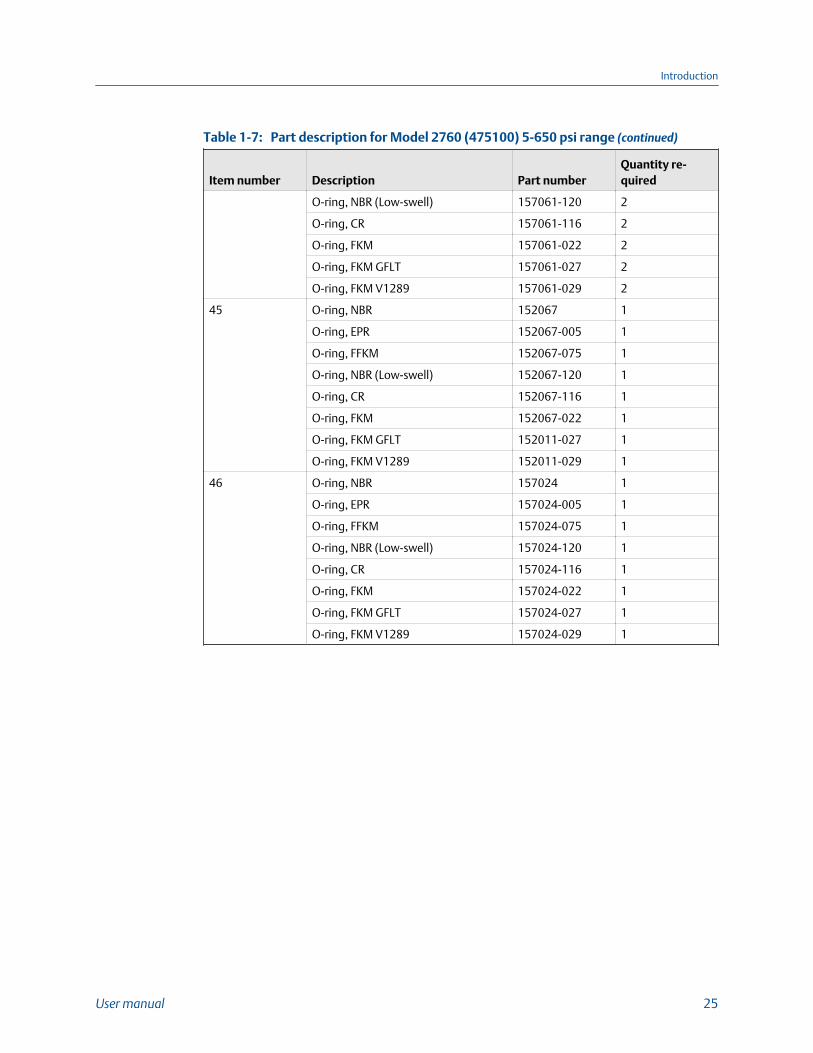
Part description for Model 2760 (475100) 5-650 psi range (continued)Table 1-7:
Item number Description Part numberQuantity re-quired
O-ring, NBR (Low-swell) 157061-120 2
O-ring, CR 157061-116 2
O-ring, FKM 157061-022 2
O-ring, FKM GFLT 157061-027 2
O-ring, FKM V1289 157061-029 2
45 O-ring, NBR 152067 1
O-ring, EPR 152067-005 1
O-ring, FFKM 152067-075 1
O-ring, NBR (Low-swell) 152067-120 1
O-ring, CR 152067-116 1
O-ring, FKM 152067-022 1
O-ring, FKM GFLT 152011-027 1
O-ring, FKM V1289 152011-029 1
46 O-ring, NBR 157024 1
O-ring, EPR 157024-005 1
O-ring, FFKM 157024-075 1
O-ring, NBR (Low-swell) 157024-120 1
O-ring, CR 157024-116 1
O-ring, FKM 157024-022 1
O-ring, FKM GFLT 157024-027 1
O-ring, FKM V1289 157024-029 1
Introduction
User manual 25
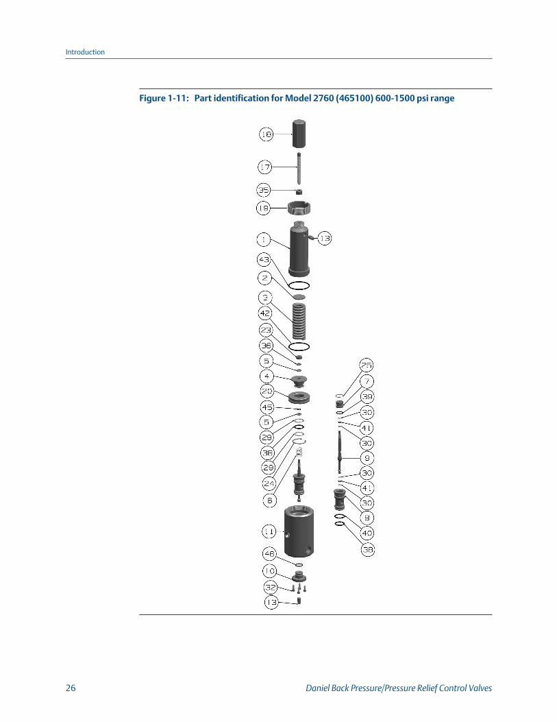
Part identification for Model 2760 (465100) 600-1500 psi rangeFigure 1-11:
Introduction
26 Daniel Back Pressure/Pressure Relief Control Valves
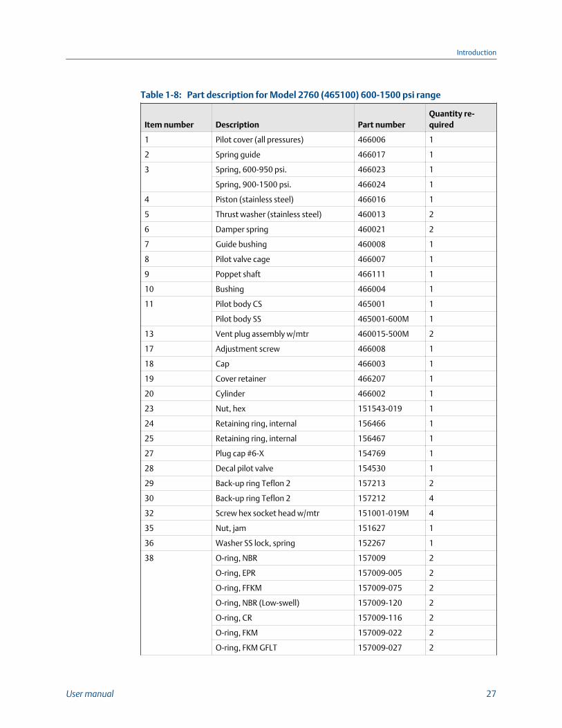
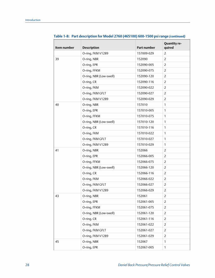
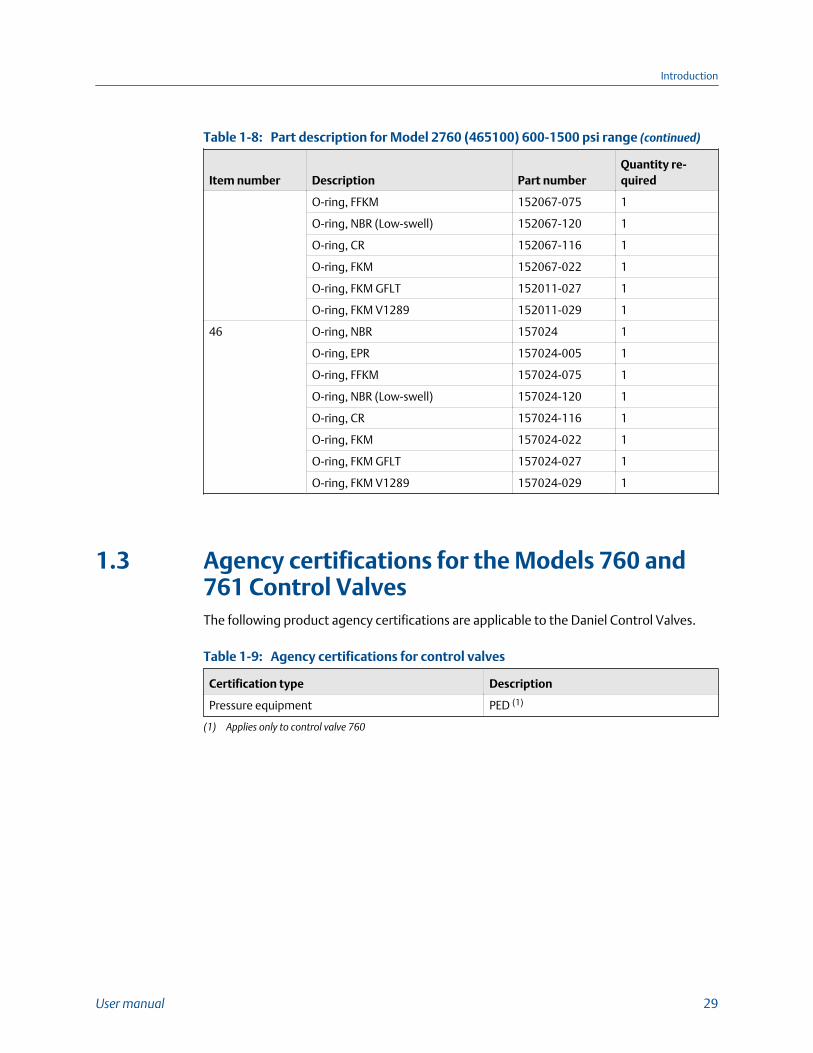
Part description for Model 2760 (465100) 600-1500 psi rangeTable 1-8:
Item number Description Part numberQuantity re-quired
1 Pilot cover (all pressures) 466006 1
2 Spring guide 466017 1
3 Spring, 600-950 psi. 466023 1
Spring, 900-1500 psi. 466024 1
4 Piston (stainless steel) 466016 1
5 Thrust washer (stainless steel) 460013 2
6 Damper spring 460021 2
7 Guide bushing 460008 1
8 Pilot valve cage 466007 1
9 Poppet shaft 466111 1
10 Bushing 466004 1
11 Pilot body CS 465001 1
Pilot body SS 465001-600M 1
13 Vent plug assembly w/mtr 460015-500M 2
17 Adjustment screw 466008 1
18 Cap 466003 1
19 Cover retainer 466207 1
20 Cylinder 466002 1
23 Nut, hex 151543-019 1
24 Retaining ring, internal 156466 1
25 Retaining ring, internal 156467 1
27 Plug cap #6-X 154769 1
28 Decal pilot valve 154530 1
29 Back-up ring Teflon 2 157213 2
30 Back-up ring Teflon 2 157212 4
32 Screw hex socket head w/mtr 151001-019M 4
35 Nut, jam 151627 1
36 Washer SS lock, spring 152267 1
38 O-ring, NBR 157009 2
O-ring, EPR 157009-005 2
O-ring, FFKM 157009-075 2
O-ring, NBR (Low-swell) 157009-120 2
O-ring, CR 157009-116 2
O-ring, FKM 157009-022 2
O-ring, FKM GFLT 157009-027 2
Introduction
User manual 27
Part description for Model 2760 (465100) 600-1500 psi range (continued)Table 1-8:
Item number Description Part numberQuantity re-quired
O-ring, FKM V1289 157009-029 2
39 O-ring, NBR 152090 2
O-ring, EPR 152090-005 2
O-ring, FFKM 152090-075 2
O-ring, NBR (Low-swell) 152090-120 2
O-ring, CR 152090-116 2
O-ring, FKM 152090-022 2
O-ring, FKM GFLT 152090-027 2
O-ring, FKM V1289 152090-029 2
40 O-ring, NBR 157010 1
O-ring, EPR 157010-005 1
O-ring, FFKM 157010-075 1
O-ring, NBR (Low-swell) 157010-120 1
O-ring, CR 157010-116 1
O-ring, FKM 157010-022 1
O-ring, FKM GFLT 157010-027 1
O-ring, FKM V1289 157010-029 1
41 O-ring, NBR 152066 2
O-ring, EPR 152066-005 2
O-ring, FFKM 152066-075 2
O-ring, NBR (Low-swell) 152066-120 2
O-ring, CR 152066-116 2
O-ring, FKM 152066-022 2
O-ring, FKM GFLT 152066-027 2
O-ring, FKM V1289 152066-029 2
43 O-ring, NBR 152061 2
O-ring, EPR 152061-005 2
O-ring, FFKM 152061-075 2
O-ring, NBR (Low-swell) 152061-120 2
O-ring, CR 152061-116 2
O-ring, FKM 152061-022 2
O-ring, FKM GFLT 152061-027 2
O-ring, FKM V1289 152061-029 2
45 O-ring, NBR 152067 1
O-ring, EPR 152067-005 1
Introduction
28 Daniel Back Pressure/Pressure Relief Control Valves
Part description for Model 2760 (465100) 600-1500 psi range (continued)Table 1-8:
Item number Description Part numberQuantity re-quired
O-ring, FFKM 152067-075 1
O-ring, NBR (Low-swell) 152067-120 1
O-ring, CR 152067-116 1
O-ring, FKM 152067-022 1
O-ring, FKM GFLT 152011-027 1
O-ring, FKM V1289 152011-029 1
46 O-ring, NBR 157024 1
O-ring, EPR 157024-005 1
O-ring, FFKM 157024-075 1
O-ring, NBR (Low-swell) 157024-120 1
O-ring, CR 157024-116 1
O-ring, FKM 157024-022 1
O-ring, FKM GFLT 157024-027 1
O-ring, FKM V1289 157024-029 1
1.3 Agency certifications for the Models 760 and761 Control ValvesThe following product agency certifications are applicable to the Daniel Control Valves.
Agency certifications for control valvesTable 1-9:
Certification type Description
Pressure equipment PED (1)
(1) Applies only to control valve 760
Introduction
User manual 29

Introduction
30 Daniel Back Pressure/Pressure Relief Control Valves
2 Operating conditions andspecificationsTopics covered in this chapter:
• Operating conditions for the Model 760 and 761
• Description of the Models 760 and 761 Control Valves
• Pilot spring selection
2.1 Operating conditions for the Model 760 and761
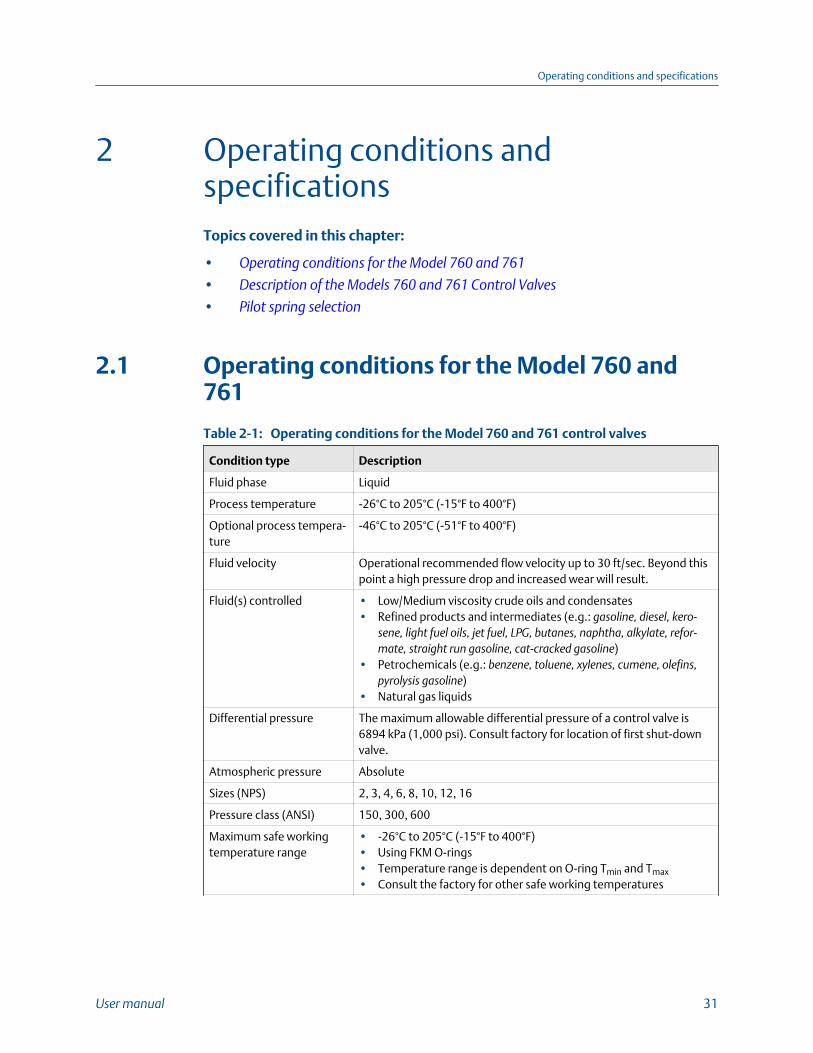
Operating conditions for the Model 760 and 761 control valvesTable 2-1:
Condition type Description
Fluid phase Liquid
Process temperature -26°C to 205°C (-15°F to 400°F)
Optional process tempera-ture
-46°C to 205°C (-51°F to 400°F)
Fluid velocity Operational recommended flow velocity up to 30 ft/sec. Beyond thispoint a high pressure drop and increased wear will result.
Fluid(s) controlled • Low/Medium viscosity crude oils and condensates• Refined products and intermediates (e.g.: gasoline, diesel, kero-
sene, light fuel oils, jet fuel, LPG, butanes, naphtha, alkylate, refor-mate, straight run gasoline, cat-cracked gasoline)
• Petrochemicals (e.g.: benzene, toluene, xylenes, cumene, olefins,pyrolysis gasoline)
• Natural gas liquids
Differential pressure The maximum allowable differential pressure of a control valve is6894 kPa (1,000 psi). Consult factory for location of first shut-downvalve.
Atmospheric pressure Absolute
Sizes (NPS) 2, 3, 4, 6, 8, 10, 12, 16
Pressure class (ANSI) 150, 300, 600
Maximum safe workingtemperature range
• -26°C to 205°C (-15°F to 400°F)• Using FKM O-rings• Temperature range is dependent on O-ring Tmin and Tmax
• Consult the factory for other safe working temperatures
Operating conditions and specifications
User manual 31
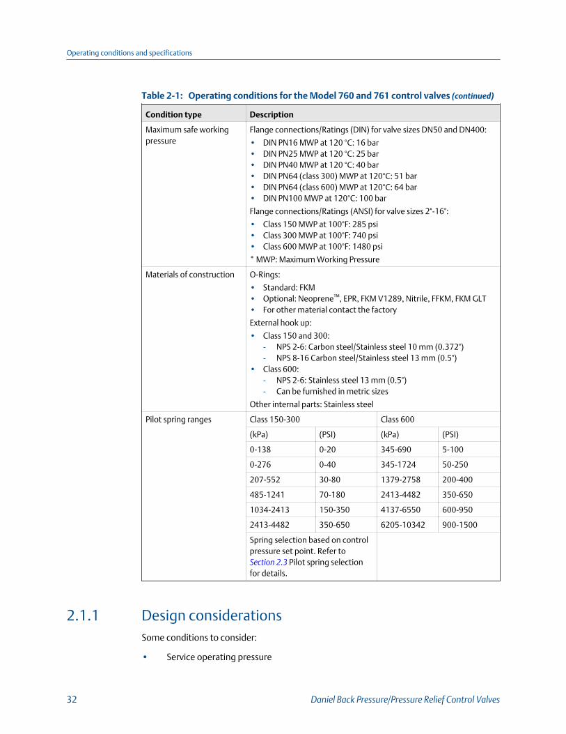
Operating conditions for the Model 760 and 761 control valves (continued)Table 2-1:
Condition type Description
Maximum safe workingpressure
Flange connections/Ratings (DIN) for valve sizes DN50 and DN400:
• DIN PN16 MWP at 120 °C: 16 bar• DIN PN25 MWP at 120 °C: 25 bar• DIN PN40 MWP at 120 °C: 40 bar• DIN PN64 (class 300) MWP at 120°C: 51 bar• DIN PN64 (class 600) MWP at 120°C: 64 bar• DIN PN100 MWP at 120°C: 100 bar
Flange connections/Ratings (ANSI) for valve sizes 2"-16":
• Class 150 MWP at 100°F: 285 psi• Class 300 MWP at 100°F: 740 psi• Class 600 MWP at 100°F: 1480 psi
* MWP: Maximum Working Pressure
Materials of construction O-Rings:
• Standard: FKM• Optional: Neoprene™, EPR, FKM V1289, Nitrile, FFKM, FKM GLT• For other material contact the factory
External hook up:
• Class 150 and 300:- NPS 2-6: Carbon steel/Stainless steel 10 mm (0.372")- NPS 8-16 Carbon steel/Stainless steel 13 mm (0.5")
• Class 600:- NPS 2-6: Stainless steel 13 mm (0.5")- Can be furnished in metric sizes
Other internal parts: Stainless steel
Pilot spring ranges Class 150-300 Class 600
(kPa) (PSI) (kPa) (PSI)
0-138 0-20 345-690 5-100
0-276 0-40 345-1724 50-250
207-552 30-80 1379-2758 200-400
485-1241 70-180 2413-4482 350-650
1034-2413 150-350 4137-6550 600-950
2413-4482 350-650 6205-10342 900-1500
Spring selection based on controlpressure set point. Refer to Section 2.3 Pilot spring selectionfor details.
2.1.1 Design considerationsSome conditions to consider:
• Service operating pressure
Operating conditions and specifications
32 Daniel Back Pressure/Pressure Relief Control Valves
• Service testing pressures
• Service process temperature and ambient site temperatures
• Chemical composition and toxicity of fluid in operating conditions
• Traffic, wind and earthquake at loading site
• Adverse force or stress caused by inadequate supports, attachments, piping, etc.
• Corrosion, erosion, fatigue, etc.
• Decomposition of unstable fluids in operating and test conditions
• Possible damage from external fire
• Mass fluid in process and test conditions
WARNING!
FUNCTIONAL AND ENVIRONMENTAL HAZARD
Evaluate the functional and environmental conditions prior to installing a control valve. Installthe control valve in a well-designed piping system.
Failure to comply may result in death or serious injury from pipe failure.
2.1.2 Environmental conditions
WARNING!
EQUIPMENT HAZARD
Never use this equipment for any purpose other than its intended use.
Failure to comply may result in death, serious personal injury and/or property damage.
Environmental conditionsTable 2-2:
Parameter type Description
Severe service conditions Ensure that piping or other attachments connected to the valveare not under stress. The design of the control valve has notbeen assessed for the effects of wind, earthquake loading andsevere weather conditions.
Additional severe service condi-tions
The valves are designed to be used on liquid applications forcrude oil and refined products.
The use of aggressive additives or oxygenates requires the useof the Aggressive Products (AP) option. The AP option valve cyl-inder incorporates cup-seals (PTFE Bal Seals) and an O-ringmade from appropriate materials for severe conditions. Materi-als for pilots such as Low Swell NBR (main valve static O-rings)and FFKM or PTFE are available.
Operating conditions and specifications
User manual 33
Environmental conditions (continued)Table 2-2:
Parameter type Description
Corrosive service Select the material compatible with the specific processes andatmospheric environments. Implement a periodic inspectionand maintenance program to ensure that pressure retainingcomponents are free from corrosion and erosion.
The valve is not designed with corrosion allowance. Inspect thevalve's metal parts periodically for corrosion and erosion, and in-spect the seals and O-rings for wear and chemical deterioration.
Low and freezing temperatures Specific gravities and viscosities at low or freezing temperaturewill reduce the flow range of the valve. Refer to Section 1.2.2 formore information.
Populated areas For new installations, locate the control valve to an area that hasfewer than 10 buildings intended for human occupancy withinan area that extends 200 meters (220 yards) radially from thecontrol valve. (Reference: Class 1 Location: U.S. DOT, CFR Title49: Part 192.5)
Closed, poorly ventilated areas Install the control valve in a well ventilated area, not less thanone meter (approximately three feet) from source of ignition orsource of heat which might damage the unit.
Elevation No limit
Humidity No limit
Proximity to open flame Provide fire prevention measures and equipment per local regu-lations.
Proximity to vehicular traffic The design of the control valve has not been assessed for the ef-fects of traffic.
2.2 Description of the Models 760 and 761 ControlValves
2.2.1 Interface requirements
WARNING!
EXCEEDING REQUIREMENTS HAZARD
Control valve requirements are defined to ensure safe equipment operation. Do not exceedpublished specifications.
Failure to comply may result in death, serious injury and/or damage to the equipment.
Operating conditions and specifications
34 Daniel Back Pressure/Pressure Relief Control Valves
Interface requirementsTable 2-3:
Requirements Description
Hydraulic lines External hook up:• ANSI class 150 and 300:
- NPS 2-6: Carbon steel/Stainless steel 10mm (0.375")
- NPS 8-16 Carbon steel/Stainless steel 13mm (0.5")
- Can be furnished in metric sizes• ANSI class 600:
- NPS 2-16: Stainless steel 13 mm (0.5")- Can be furnished in metric sizes
Flange type The mechanical connections for Model 760 and761 control valves are standard class 150, 300and 600 ANSI R.F. flanges which are availableonly in stainless steel. Other types of flange con-nections are available per customer request forDaniel control valves. For other ANSI ratings orflanges consult the factory engineers. For maxi-mum working pressures at intermediate tem-peratures refer to ANSI B16.5.
WARNING!
FLANGE SIZE HAZARD
Customers must choose the appropriate size material of the flange for their pipingrequirements.
Choosing an incorrect flange may cause a pressure leak, resulting in death or serious injury.
2.2.2 Requirements and limitations for installation
NOTICE
Comply with local government regulations and company requirements.
See Figure 2-1 for flow direction.
NOTICE
Flush lines to remove welding bead, pipe scale, etc.
Operating conditions and specifications
User manual 35
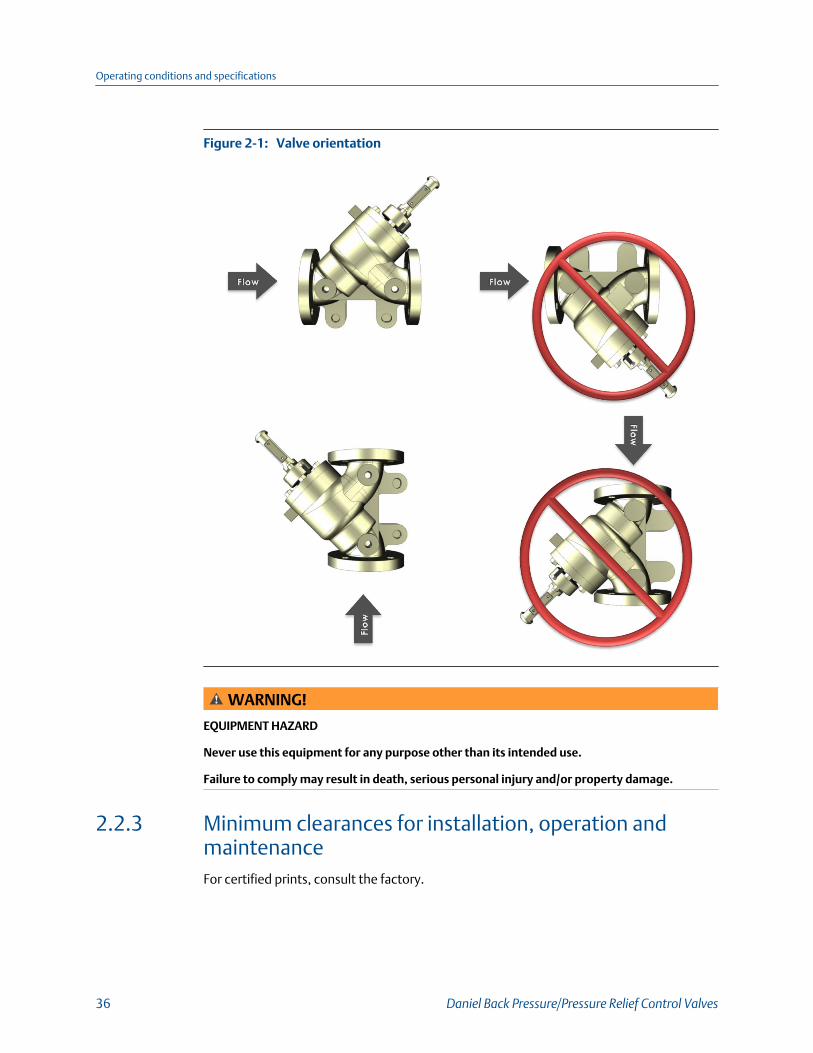
Valve orientationFigure 2-1:
WARNING!
EQUIPMENT HAZARD
Never use this equipment for any purpose other than its intended use.
Failure to comply may result in death, serious personal injury and/or property damage.
2.2.3 Minimum clearances for installation, operation andmaintenanceFor certified prints, consult the factory.
Operating conditions and specifications
36 Daniel Back Pressure/Pressure Relief Control Valves
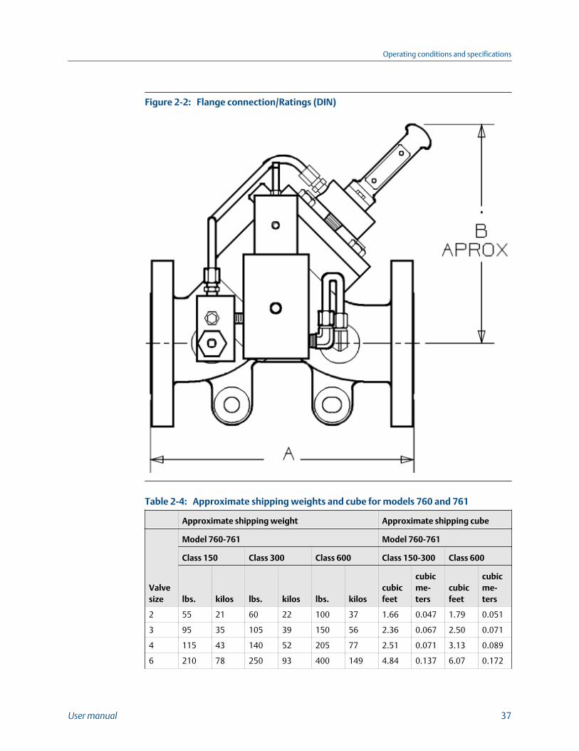
Flange connection/Ratings (DIN)Figure 2-2:
Approximate shipping weights and cube for models 760 and 761Table 2-4:
Approximate shipping weight Approximate shipping cube
Valvesize
Model 760-761 Model 760-761
Class 150 Class 300 Class 600 Class 150-300 Class 600
lbs. kilos lbs. kilos lbs. kiloscubicfeet
cubicme-ters
cubicfeet
cubicme-ters
2 55 21 60 22 100 37 1.66 0.047 1.79 0.051
3 95 35 105 39 150 56 2.36 0.067 2.50 0.071
4 115 43 140 52 205 77 2.51 0.071 3.13 0.089
6 210 78 250 93 400 149 4.84 0.137 6.07 0.172
Operating conditions and specifications
User manual 37
Approximate shipping weights and cube for models 760 and 761(continued)Table 2-4:
Approximate shipping weight Approximate shipping cube
Valvesize
Model 760-761 Model 760-761
Class 150 Class 300 Class 600 Class 150-300 Class 600
lbs. kilos lbs. kilos lbs. kiloscubicfeet
cubicme-ters
cubicfeet
cubicme-ters
8 400 149 465 174 725 271 8.94 0.253 9.98 0.283
10 640 239 700 261 1170 437 12.08 0.342 15.13 0.428
12 1040 388 1215 454 1820 679 20.25 0.573 21.94 0.621
16 CF CF CF CF CF CF 39.53 1.119 42.17 1.194
CF=consult factory
2.3 Pilot spring selection
2.3.1 Pilot spring selection tableThe following Pilot spring selections table is a complete listing of regulating pilot valvefigure numbers, part numbers, pilot springs, spring part numbers, and piston diameters.
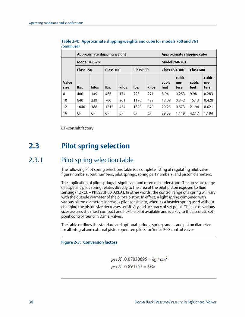
The application of pilot springs is significant and often misunderstood. The pressure rangeof a specific pilot spring relates directly to the area of the pilot piston exposed to fluidsensing (FORCE = PRESSURE X AREA). In other words, the control range of a spring will varywith the outside diameter of the pilot's piston. In effect, a light spring combined withvarious piston diameters increases pilot sensitivity, whereas a heavier spring used withoutchanging the piston size decreases sensitivity and accuracy of set point. The use of varioussizes assures the most compact and flexible pilot available and is a key to the accurate setpoint control found in Daniel valves.
The table outlines the standard and optional springs, spring ranges and piston diametersfor all integral and external piston operated pilots for Series 700 control valves.
Conversion factorsFigure 2-3:
Operating conditions and specifications
38 Daniel Back Pressure/Pressure Relief Control Valves
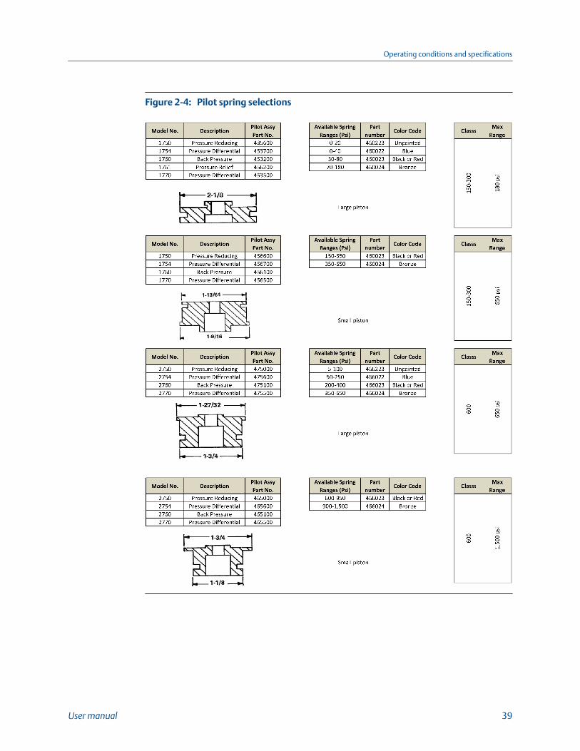
Pilot spring selectionsFigure 2-4:
Operating conditions and specifications
User manual 39
2.3.2 Table usageExample: A customer has an ANSI 300 lb. Model 760 Back Pressure Valve with a 207-552kPa (30-80 psi) pilot spring set for 483 kPa (70 psi) control. Due to change in the system,he desires to control a 300 psi 2068 kPa (300 psi) downstream pressure. For a spring rangeof 1034-2413 kPa (150-350 psi) the table lists a 460023 spring. But the existing springrange of 207-552 kPa (30-80 psi) also requires a 460023 spring.
Conclusion: Changing the spring will not solve this customer's problem. The pilot pistonmust be changed.
Proper use of the pilot spring selection table should eliminate any difficulty associated withchanging a pilot spring. If any two facts are known about a pilot, other tabulated data canbe determined. For example:
• Knowledge of piston diameter and spring color indicates the spring range of thepilot.
• Knowledge of the model number and piston diameter indicates the pilot partnumber.
• Knowledge of the pilot part number and spring color indicates the spring range.
Operating conditions and specifications
40 Daniel Back Pressure/Pressure Relief Control Valves
Part IIInstall
Install
User manual 41
Install
42 Daniel Back Pressure/Pressure Relief Control Valves
3 Installation prerequisitesTopics covered in this chapter:
• Models 760 and 761 pre-start checks
• Model 760 and 761 installation
3.1 Models 760 and 761 pre-start checks
CAUTION!
EQUIPMENT HAZARD
Observe all precautionary signs posted on the equipment.
Failure to comply may result in injury to personnel or cause damage to the equipment.
ImportantThe Daniel valve may be installed with a flow direction horizontal or vertical up but should never beinstalled with flow direction vertical down. When installed in a horizontal line, the valve should beinstalled so that the cylinder head is at the top of the valve and not the bottom.
Installation prerequisites
User manual 43
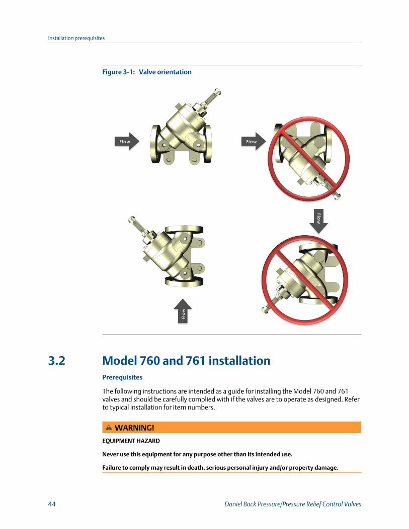
Valve orientationFigure 3-1:
3.2 Model 760 and 761 installationPrerequisites
The following instructions are intended as a guide for installing the Model 760 and 761valves and should be carefully complied with if the valves are to operate as designed. Referto typical installation for item numbers.
WARNING!
EQUIPMENT HAZARD
Never use this equipment for any purpose other than its intended use.
Failure to comply may result in death, serious personal injury and/or property damage.
Installation prerequisites
44 Daniel Back Pressure/Pressure Relief Control Valves
Procedure
1. If possible, install the control valve within 7.6 M (25 feet) of the point at whichupstream line pressure is to be controlled. This distance limitation is due to thesense line which must be run to the pilot. Consult the factory if sense lines of greaterlength are required.
ImportantIt is recommended that the control valve be installed between isolating valves. This willpermit the system to remain operational while maintenance is being performed on the valve.
2. Ensure that the line is completely free of all foreign material before the valve isbolted into the line.
a. If it is impractical to flush the line before installing the valve, bolt in spool piece orthe valve body. Remove the cylinder assembly per the disassembly instructionson the basic valve and seal the opening with a temporary cover.
b. Disconnect or isolate the sense line if it is connected to the pilot. This willeliminate the possibility of foreign material flowing into the sensing chamber ofthe pilot. (Flushing will not be necessary if the product line and liquid arepositively known to be clean.)
3. One 3/8" (1760/1761) or 1/2" (2760) sense line is required between the pilot and theupstream sense point. The size line is a minimum requirement based on a maximumproduct viscosity of 500 SSU. Use a larger size sense line if the viscosity of theproduct is in excess of 500 SSU. This sense line is mated with the lower connectionof the pilot.
4. Installing a pressure gauge in the valve circuit is recommended. This gauge willmonitor the upstream pressure. In order to monitor and adjust the valve properly, itis very important that the gauge be installed at the upstream sense point located onthe valve schematic. The pressure gauge is not furnished with the Daniel controlvalve and will need to be sourced from a third party.
5. Verify that the 1760, 1761 or 2760 pilots set point is correct as ordered. A paper tagis attached to the pilot with the factory set point. The set point can be changed inthe field to any set point within the pilot spring range. Refer to Figure C-1 and Figure C-2.
Installation prerequisites
User manual 45
Installation prerequisites
46 Daniel Back Pressure/Pressure Relief Control Valves
Part IIIOperate
Operate
User manual 47
Operate
48 Daniel Back Pressure/Pressure Relief Control Valves
4 Operation start upTopics covered in this chapter:
• Model 760 adjustment and startup
• Model 761 adjustment and startup
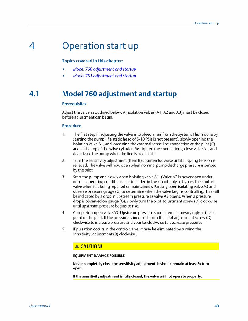
4.1 Model 760 adjustment and startupPrerequisites
Adjust the valve as outlined below. All isolation valves (A1, A2 and A3) must be closedbefore adjustment can begin.
Procedure
1. The first step in adjusting the valve is to bleed all air from the system. This is done bystarting the pump (if a static head of 5-10 PSIs is not present), slowly opening theisolation valve A1, and loosening the external sense line connection at the pilot (C)and at the top of the valve cylinder. Re-tighten the connections, close valve A1, anddeactivate the pump when the line is free of air.
2. Turn the sensitivity adjustment (Item B) counterclockwise until all spring tension isrelieved. The valve will now open when nominal pump discharge pressure is sensedby the pilot
3. Start the pump and slowly open isolating valve A1. (Valve A2 is never open undernormal operating conditions. It is included in the circuit only to bypass the controlvalve when it is being repaired or maintained). Partially open isolating valve A3 andobserve pressure gauge (G) to determine when the valve begins controlling. This willbe indicated by a drop in upstream pressure as valve A3 opens. When a pressuredrop is observed on gauge (G), slowly turn the pilot adjustment screw (D) clockwiseuntil upstream pressure begins to rise.
4. Completely open valve A3. Upstream pressure should remain unvaryingly at the setpoint of the pilot. If the pressure is incorrect, turn the pilot adjustment screw (D)clockwise to increase pressure and counterclockwise to decrease pressure.
5. If pulsation occurs in the control valve, it may be eliminated by turning thesensitivity, adjustment (B) clockwise.
CAUTION!
EQUIPMENT DAMAGE POSSIBLE
Never completely close the sensitivity adjustment. It should remain at least ¼ turnopen.
If the sensitivity adjustment is fully closed, the valve will not operate properly.
Operation start up
User manual 49
The sensitivity adjustment may also be used to regulate the speed of valve response.By turning the sensitivity control clockwise, the opening speed of the valve will beincreased, and the closing speed will be decreased. An opposite effect occurs if thesensitivity control is turned counterclockwise.
Back pressure Model 760Figure 4-1:
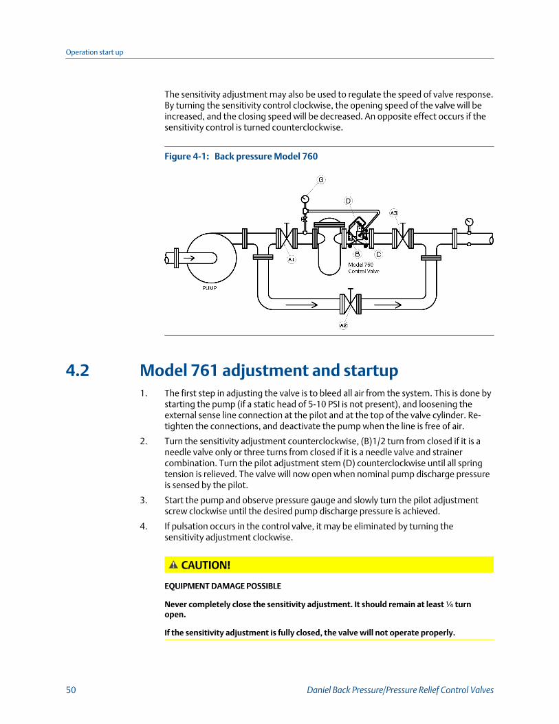
4.2 Model 761 adjustment and startup1. The first step in adjusting the valve is to bleed all air from the system. This is done by
starting the pump (if a static head of 5-10 PSI is not present), and loosening theexternal sense line connection at the pilot and at the top of the valve cylinder. Re-tighten the connections, and deactivate the pump when the line is free of air.
2. Turn the sensitivity adjustment counterclockwise, (B)1/2 turn from closed if it is aneedle valve only or three turns from closed if it is a needle valve and strainercombination. Turn the pilot adjustment stem (D) counterclockwise until all springtension is relieved. The valve will now open when nominal pump discharge pressureis sensed by the pilot.
3. Start the pump and observe pressure gauge and slowly turn the pilot adjustmentscrew clockwise until the desired pump discharge pressure is achieved.
4. If pulsation occurs in the control valve, it may be eliminated by turning thesensitivity adjustment clockwise.
CAUTION!
EQUIPMENT DAMAGE POSSIBLE
Never completely close the sensitivity adjustment. It should remain at least ¼ turnopen.
If the sensitivity adjustment is fully closed, the valve will not operate properly.
Operation start up
50 Daniel Back Pressure/Pressure Relief Control Valves
The sensitivity adjustment may also be used to regulate the speed of valve response.By turning the sensitivity control clockwise, the opening speed of the valve will beincreased, and the closing speed will be decreased. An opposite effect occurs if thesensitivity control is turned counterclockwise.
Pressure relief/Pump bypass Model 761Figure 4-2:
Operation start up
User manual 51
Operation start up
52 Daniel Back Pressure/Pressure Relief Control Valves
Part IVMaintain
Chapters covered in this part:
• Planned maintenance
• Spare parts
Maintain
User manual 53
Maintain
54 Daniel Back Pressure/Pressure Relief Control Valves
5 Planned maintenanceTopics covered in this chapter:
• Maintenance considerations
• Pilot disassembly (1760/1761)
• Pilot disassembly (2760)
• Pilot assembly (760/761)
5.1 Maintenance considerationsInspect and clean all pilots and their parts at regularly scheduled intervals. All O-ringsshould be checked for nicks, cuts and wear. Any defective or doubtful O-rings should bereplaced.
1. Remove the strainer (combination valve and strainer unit) by removing the strainercap.
2. All parts associated with the adjustment stem are removable when the strainer isremoved. The adjustment stem must be removed by turning counterclockwise.
3. Reassemble by reversing disassembly order. Be careful not to cut O-rings whenassembling parts and assemblies. Be sure spring under the sensing piston is in place.
• Retaining ring pliers
• Ratchet wrench
• Pin removal tool
• Needle nose pliers
Planned maintenance
User manual 55
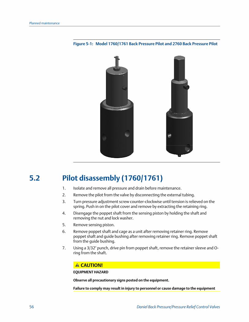
Model 1760/1761 Back Pressure Pilot and 2760 Back Pressure PilotFigure 5-1:
5.2 Pilot disassembly (1760/1761)1. Isolate and remove all pressure and drain before maintenance.
2. Remove the pilot from the valve by disconnecting the external tubing.
3. Turn pressure adjustment screw counter-clockwise until tension is relieved on thespring. Push in on the pilot cover and remove by extracting the retaining ring.
4. Disengage the poppet shaft from the sensing piston by holding the shaft andremoving the nut and lock washer.
5. Remove sensing piston.
6. Remove poppet shaft and cage as a unit after removing retainer ring. Removepoppet shaft and guide bushing after removing retainer ring. Remove poppet shaftfrom the guide bushing.
7. Using a 3/32" punch, drive pin from poppet shaft, remove the retainer sleeve and O-ring from the shaft.
CAUTION!EQUIPMENT HAZARD
Observe all precautionary signs posted on the equipment.
Failure to comply may result in injury to personnel or cause damage to the equipment
Planned maintenance
56 Daniel Back Pressure/Pressure Relief Control Valves
CAUTION!
BENT SHAFT HAZARD
Be careful to avoid bending the shaft when using the punch.
The shaft can be easily bent when using the punch incorrectly.
Failure to comply may result in injury to personnel or cause damage to equipment.
8. Remove and inspect all O-rings.
5.3 Pilot disassembly (2760)1. Isolate and remove all pressure and drain before maintenance.
2. Remove the pilot from the valve by disconnecting the external tubing.
3. Turn pressure adjustment screw counter-clockwise until tension is relieved on thespring. Push in on the pilot cover and remove by extracting cover retainer. Unscrewcounter-clockwise.
4. Disengage the poppet shaft assembly from the sensing piston by holding the shaftand removing the nut and lock washer.
5. Remove sensing piston.
6. Remove the poppet shaft and cage as a unit after removing the retainer ring.Remove the poppet shaft and remove the nut, the lock washer and the retainersleeve. Remove the guide bushing by removing the retainer ring.
7. Remove and inspect all O-rings.
CAUTION!
EQUIPMENT HAZARD
Observe all precautionary signs posted on the equipment.
Failure to comply may result in injury to personnel or cause damage to the equipment.
CAUTION!
BENT SHAFT HAZARD
Be careful to avoid bending the shaft when using the punch.
The shaft can be easily bent when using the punch incorrectly.
Failure to comply may result in injury to personnel or cause damage to equipment.
Planned maintenance
User manual 57
5.4 Pilot assembly (760/761)1. For pilots used on crude oil, gasoline, diesel fuel or other general liquid hydrocarbon
service, apply a light oil or general purpose grease to all O-rings to prevent cuttingand to facilitate assembly. Use a light oil only for Butane and Propane service.
2. Reassemble by reversing disassembly order. Be careful not to cut O-rings whenassembling parts and assemblies. Be sure spring (Item 21) under the sensing pistonis in place.
ImportantThis pilot was designed without corrosion allowance. The valve's metal parts should beperiodically inspected for corrosion and erosion. The seals and O-rings should be inspected forwear and chemical deterioration.
ImportantEnsure that piping or other attachments connected to the control valve are not under stress.
ImportantProvide fire prevention measures and equipment per local regulations.
Planned maintenance
58 Daniel Back Pressure/Pressure Relief Control Valves
6 Spare partsTopics covered in this chapter:
• Recommended spare parts
• Order spare parts
6.1 Recommended spare parts
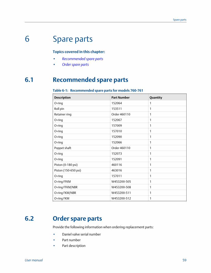
Recommended spare parts for models 760-761Table 6-1:
Description Part Number Quantity
O-ring 152064 1
Roll pin 153511 1
Retainer ring Order 460110 1
O-ring 152067 1
O-ring 157009 1
O-ring 157010 1
O-ring 152090 1
O-ring 152066 1
Poppet shaft Order 460110 1
O-ring 152073 1
O-ring 152091 1
Piston (0-180 psi) 460116 1
Piston (150-650 psi) 463016 1
O-ring 157011 1
O-ring FFKM W453200-505 1
O-ring FFKM/NBR W453200-508 1
O-ring FKM/NBR W453200-511 1
O-ring FKM W453200-512 1
6.2 Order spare partsProvide the following information when ordering replacement parts:
• Daniel valve serial number
• Part number
• Part description
Spare parts
User manual 59
• Quantity required
• Size
• Product, product viscosity, product specific gravity
• Minimum and maximum operating temperatures
• Minimum and maximum flow rates
• Minimum, normal and maximum operating pressure
• Control functions to be performed
• Flange connections
• O-ring material
• Control pilot materials
• Tubing material
• Main valve piston material
Spare parts
60 Daniel Back Pressure/Pressure Relief Control Valves
Appendix ACombination needle valve and strainer
Topics covered in this appendix:
• Disassembly and assembly
• Needle valve and strainer combination
• Order spare parts
A.1 Disassembly and assemblyProcedure
1. Isolate and remove all pressure and drain before maintenance.
2. Remove strainer (combination valve and strainer unit) by removing the strainer cap.
3. All parts associated with the adjustment stem are removable when the retainer isremoved. Remove the adjustment stem by turning it counterclockwise.
4. For pilots used on crude oil, gasoline, diesel fuel or other general liquid hydrocarbonservice, apply a light oil or general purpose grease to all O-rings to prevent cuttingand to facilitate assembly. Use a light oil only for Butane and Propane service.
Tools required:
• Retaining ring pliers
• Ratchet wrench
• Pin removal tool
• Needle nose pliers
Combination needle valve and strainer
User manual 61
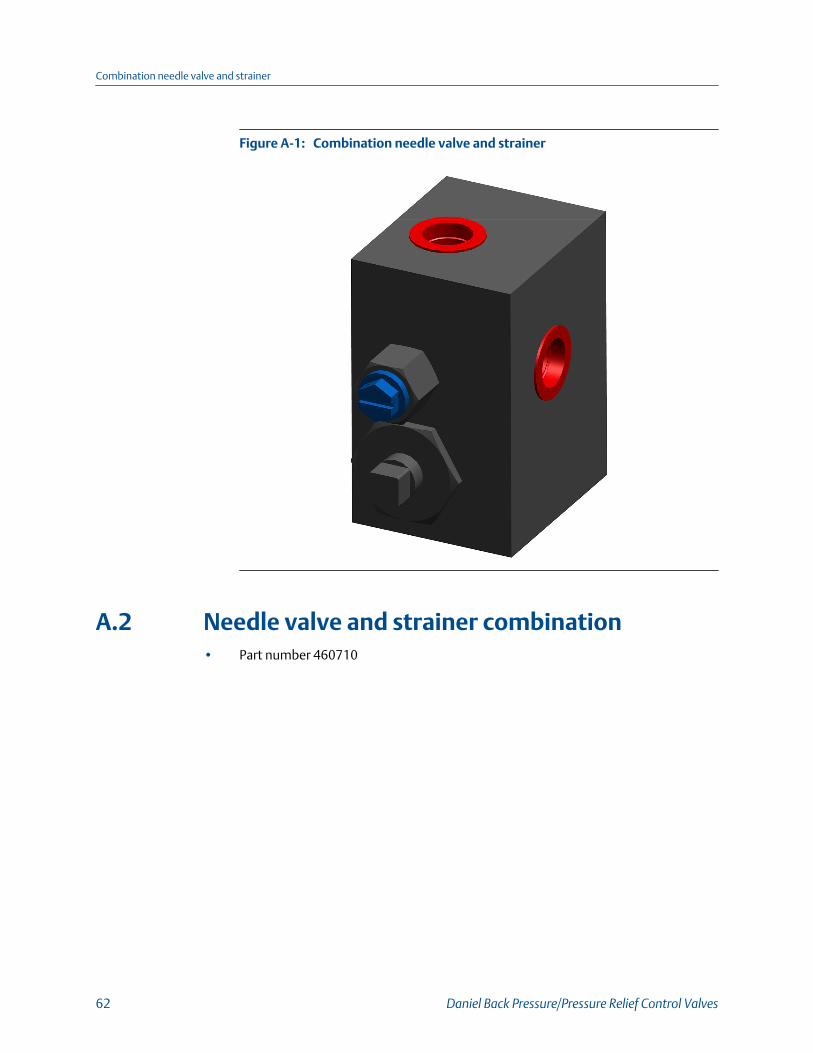
Combination needle valve and strainerFigure A-1:
A.2 Needle valve and strainer combination• Part number 460710
Combination needle valve and strainer
62 Daniel Back Pressure/Pressure Relief Control Valves
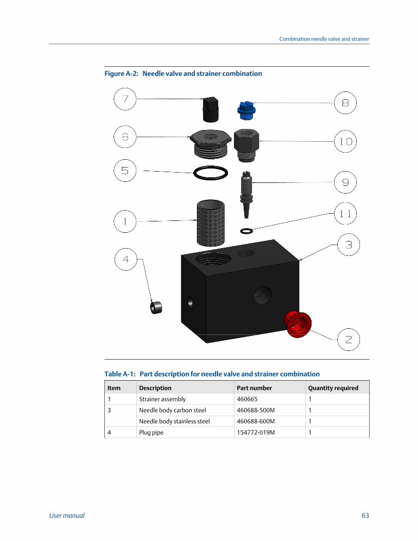
Needle valve and strainer combinationFigure A-2:
Part description for needle valve and strainer combinationTable A-1:
Item Description Part number Quantity required
1 Strainer assembly 460665 1
3 Needle body carbon steel 460688-500M 1
Needle body stainless steel 460688-600M 1
4 Plug pipe 154772-019M 1
Combination needle valve and strainer
User manual 63
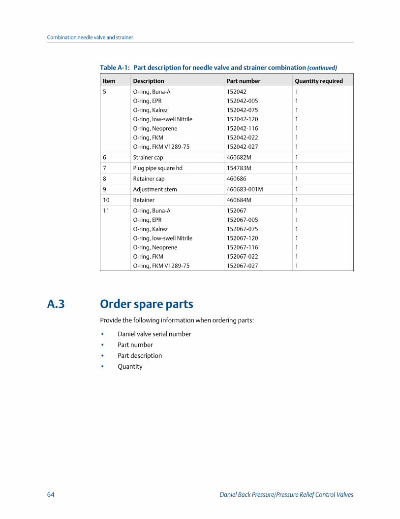
Part description for needle valve and strainer combination (continued)Table A-1:
Item Description Part number Quantity required
5 O-ring, Buna-A
O-ring, EPR
O-ring, Kalrez
O-ring, low-swell Nitrile
O-ring, Neoprene
O-ring, FKM
O-ring, FKM V1289-75
152042
152042-005
152042-075
152042-120
152042-116
152042-022
152042-027
1
1
1
1
1
1
1
6 Strainer cap 460682M 1
7 Plug pipe square hd 154783M 1
8 Retainer cap 460686 1
9 Adjustment stem 460683-001M 1
10 Retainer 460684M 1
11 O-ring, Buna-A
O-ring, EPR
O-ring, Kalrez
O-ring, low-swell Nitrile
O-ring, Neoprene
O-ring, FKM
O-ring, FKM V1289-75
152067
152067-005
152067-075
152067-120
152067-116
152067-022
152067-027
1
1
1
1
1
1
1
A.3 Order spare partsProvide the following information when ordering parts:
• Daniel valve serial number
• Part number
• Part description
• Quantity
Combination needle valve and strainer
64 Daniel Back Pressure/Pressure Relief Control Valves
Appendix BRelief valve pilot bypass
Topics covered in this appendix:
• Introduction
• Operation
• Primary pilot valve
• Secondary pilot valve
• Pilot control set points
• Installation
• Adjustments
• Needle valves
• Micro Switch
• Pilot line block valves
B.1 Introduction
CAUTION!
INSTRUCTIONS HAZARD
Read this publication entirely before performing any operation.
Failure to understand and follow these instructions could result in serious personal injuryand/or damage to the equipment.
CAUTION!
REPAIR HAZARD
Should this equipment require repair or adjustment, contact the nearest Daniel Measurementand Control sales office.
It is important that servicing be performed only by trained and qualified service personnel.
If this equipment is not properly serviced, serious personal injury and/or damage to theequipment could result.
The Model 760 Relief Valve is a normally closed, pilot operated, "safety valve". It remains ina closed position unless an abnormal line pressure rises above safe operating conditions oran established maximum. Once the pressure reaches the predetermined maximum, themodel 760 valve "must open" dissipating excess pressure that could rupture the pipe line.
Relief valve pilot bypass
User manual 65
B.2 OperationThe 760 valve is equipped with two (2) relief pilots. Each pilot continuously monitors linepressure to control the opening and closing of the main valve.
B.3 Primary pilot valveThe primary regulator, a 1760 Pilot Valve, is spring set (adjustable) and the minimum tomaximum range of the spring is tamped on the nameplate of the valve body. The 1760pilot senses line pressure by an external sense line to the inlet side of the valve. When apressure rise equal to or greater than the pilot's spring tension occurs, the pilot opens,causing the main valve to open.
B.4 Secondary pilot valveIf the 1760 pilot valve fails to open, the secondary relief pilot will take control at aminimum of 10 psi above the set point of the 1760 pilot. The secondary pilot is a CircleSeal direct operated relief valve. It is mounted inline and has no external adjustments,insuring complete tamper proof operation. Regardless of mis-adjustments, failure of the1760 pilot, or tampering, the secondary pilot will open the main valve very rapidly. It ispiped so that its flow path is restrictionless.
B.5 Pilot control set pointsThe 1760 pilot valve and the Circle Seal pilot have been factory set to open at a specifiedpressure. These settings should be checked before attempting any adjustments. The 1760pilot setting is on a tag attached to the pilot, and the Circle Seal valve setting is stampedon its body.
ImportantThe 1760 pilot (primary) must be set at least 10 psi lower than the Circle Seal Relief Valve(secondary).
B.6 InstallationThe Model 760 valve should be installed as illustrated in the accompanying schematic,which indicates block valves in the pilot lines, a sense line to the 1760 pilot piped with teefor testing set point, and a micro switch for remote indication of an open valve. Theseoptions may not be included on your valve. Unless pre-piped at the factory, a sense linefrom the 1760 pilot to the upstream side of the valve in this sense line is recommended.With the valve properly installed and the 1760 pilot sense line connected, it is necessary tobleed air from the 1760 pilot sense line and from the rear of the main valve piston. Slowly
Relief valve pilot bypass
66 Daniel Back Pressure/Pressure Relief Control Valves
allow line product to enter the valve inlet. Loosen the tubing fittings of the sense line asconnected to the 1760 pilot valve and the fitting connected to the top of the main valvepiston chamber. Dissipate all air and retighten fittings.
B.7 Adjustments1760 PILOT: This pilot has been factory set according to instructions received. To check thesetting, it will be necessary to do one of two things:
1. Allow pressure to build up on the valve inlet until it begins to open. The pressurereading on initial valve opening would be set-point.
2. Use a "dead weight tester" or some hydraulic pressure device, by closing off the pilotsense line and inducing pressure directly to the 1760 pilot sensing chamber. Initialopening of the main valve would indicate set point.
Turning the 1760 pilot adjustment stem CW increases pressure set point, CCW decreases.NOTE: The maximum setting of the 1760 pilot is 10 psi less than the Circle Seal relief pilotset point. To change the setting of the Circle Seal pilot it must be removed from the valveand bench tested, or returned to the factory.
B.8 Needle valvesThe needle valve contained in the combination needle valve and strainer is a sensitivity andclosing speed adjustment. The Pneu-trol valve is an opening speed adjustment. Nominalturns open from a closed position are as follows:
Valve size Sensitivity (closing speed) Pneu-trol (opening speed)
2" 3/4 Turn 1/4 Turn
3" 1 Turn 1/4 Turn
4" 1-1/4 Turn 1/2 Turn
6" 2 Turn 1/2 Turn
8" 2-1/2 Turn 1 Turn
10" 3-1/2 Turn 1-1/4 Turn
12" 4 Turn 1-1/2 Turn
Turn needle valve CCW to increase closing speed or opening speed. CW directiondecreases closing speed or opening speed.
Relief valve pilot bypass
User manual 67
B.9 Micro SwitchAn optional feature, the micro switch is actuated by the adjustable cam on the valveposition indicator. Moving the cam up or down on the stem determines the point of valveopening at which the switch is actuated. Normally the switch is adjusted to indicate initialvalve opening (factory set).
B.10 Pilot line block valvesThese are optional features but most valves include those labeled B and E. Block valves areused to isolate the pilot lines for various reasons:
• Closing block valve (A), permits testing the 1760 pilot valve set point when using a"dead weight tester" or some auxiliary hydraulic device.
• Closing block valves (B), (C), and (E) allows removal of the 1760 pilot with the CircleSeal valve still operable.
• Opening block valve (D) permits the Model 760 valve to open fully for emergency orother reasons.
• Block valves (F) and (G) permit attachment of temporary pressure gauges.
For normal operation, the block valves should be in the following positions:
Normally open: (A), (B), (C), and (E)
Normally closed: (D), (F), and (G)
Relief valve pilot bypass
68 Daniel Back Pressure/Pressure Relief Control Valves
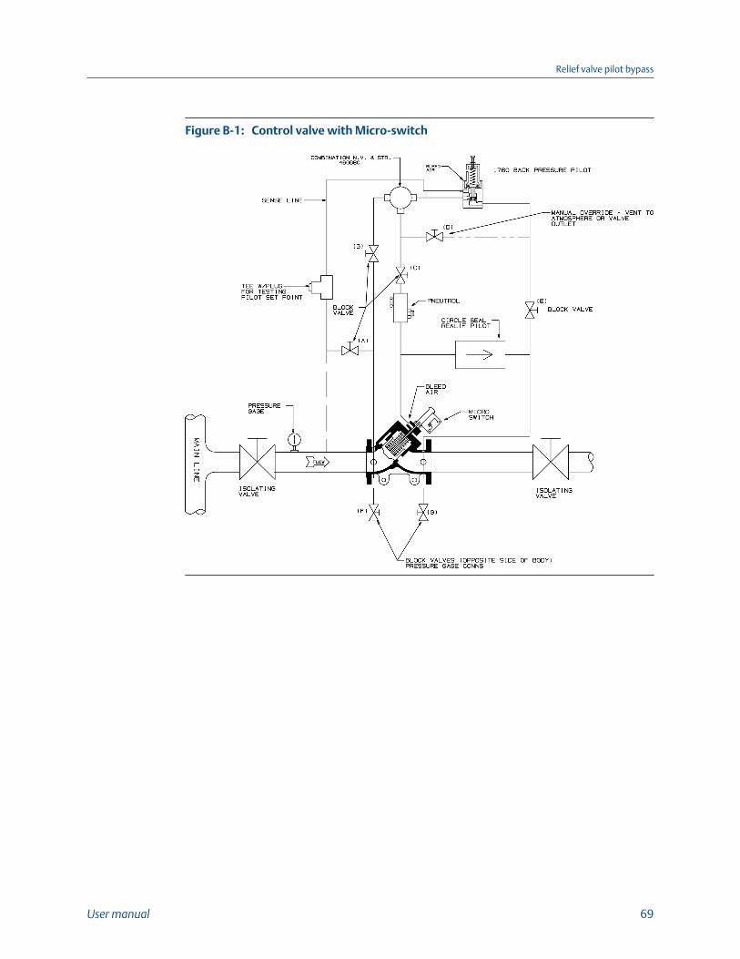
Control valve with Micro-switchFigure B-1:
Relief valve pilot bypass
User manual 69
Relief valve pilot bypass
70 Daniel Back Pressure/Pressure Relief Control Valves
Appendix CTesting Daniel Model 1760/1761 or 2760Relief valve pilot set point in the field
C.1 Testing models 1760/1761 or 2760
ImportantThe test described below confirms pilot set point setting and main valve functionality. The open pilotsignals the main valve to open. In order for the main valve to open there must be a minimum of 5 psidifferential pressure from valve inlet to valve outlet and there must be flow available in the pipeline.The Daniel pilot operated valve will not open if there is another valve closed on the downstream side.
Prerequisites
Refer to drawings attached (Figure C-1) for external Sense line installed by customer or(Figure C-2) for the Factory installed sense line.
Procedure
1. Install (A), (B) and (C) in pilot sense line.
Note: Sense lines can be fitted at the factory or installed in the field by the customer.
2. Normal operation
a. (A) Valve OPEN
b. (B) Valve OPEN
c. (C) Tee CLOSED (Plugged)
3. Testing set point with external pressure source
a. (A) Valve CLOSED
b. (B) Valve OPEN
c. (C) Tee - Remove plug, drain and attach pressure source with pressure gauge.Gradually apply pressure until set point is reached and valve begins to open. Setpoint may be raised or lowered by adjusting the set screw on top of the pilotclockwise (to increase), counterclockwise (to decrease). Verify with pressuregauge on external pressure bottle. At the conclusion of test remove pressuresource, return pipe plug to (C), open block valve (A) and return valve to normaloperation.
4. Install (A), (B) and (C) in pilot sense line.
Note: Sense lines can be fitted at the factory or installed in the field by the customer.
5. Normal operation
a. (A) Valve OPEN
Testing Daniel Model 1760/1761 or 2760 Relief valve pilot set point in the field
User manual 71
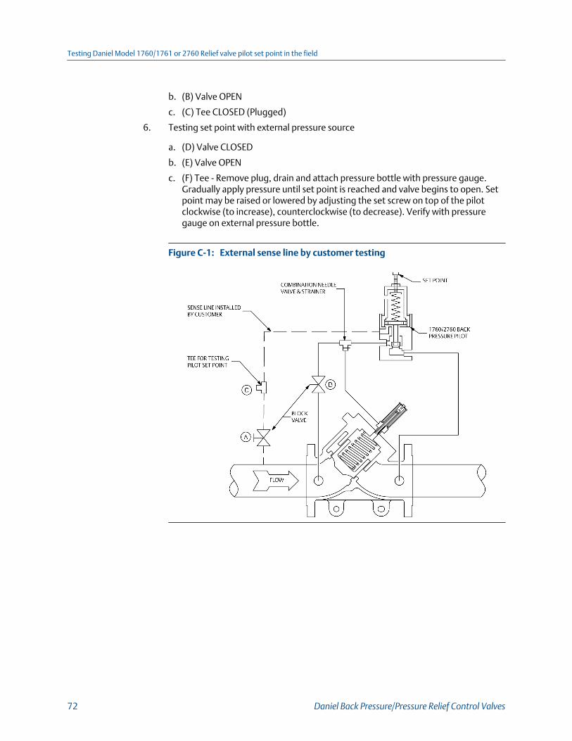
b. (B) Valve OPEN
c. (C) Tee CLOSED (Plugged)
6. Testing set point with external pressure source
a. (D) Valve CLOSED
b. (E) Valve OPEN
c. (F) Tee - Remove plug, drain and attach pressure bottle with pressure gauge.Gradually apply pressure until set point is reached and valve begins to open. Setpoint may be raised or lowered by adjusting the set screw on top of the pilotclockwise (to increase), counterclockwise (to decrease). Verify with pressuregauge on external pressure bottle.
External sense line by customer testingFigure C-1:
Testing Daniel Model 1760/1761 or 2760 Relief valve pilot set point in the field
72 Daniel Back Pressure/Pressure Relief Control Valves
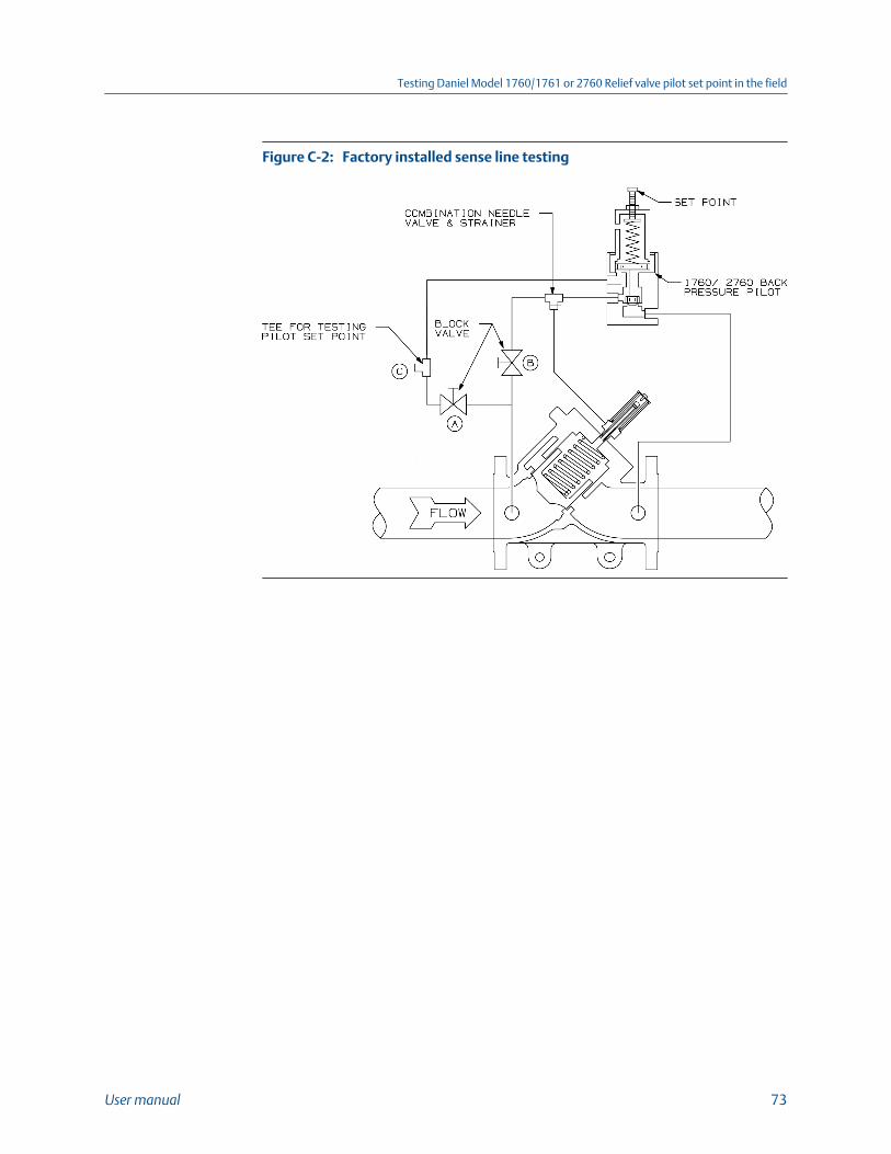
Factory installed sense line testingFigure C-2:
Testing Daniel Model 1760/1761 or 2760 Relief valve pilot set point in the field
User manual 73
Testing Daniel Model 1760/1761 or 2760 Relief valve pilot set point in the field
74 Daniel Back Pressure/Pressure Relief Control Valves

Testing Daniel Model 1760/1761 or 2760 Relief valve pilot set point in the field
User manual 75
P/N 3-9008-558
Rev G
2018
Emerson Process ManagementDaniel Measurement and Control, Inc.North America / Latin America:HeadquartersUSA - Houston, TexasT +1.713.467.6000USA Toll Free 1.888.FLOW.001www.EmersonProcess.com/Daniel
Europe: Stirling, Scotland, UKT +44.1786.433400Middle East, Africa: Dubai, UAET +971.4.811.8100Asia Pacific: SingaporeT +65.6777.8211
©2018 Daniel Measurement and Control, Inc. All rights reserved. Unauthorized duplication in wholeor part is prohibited. Printed in the USA.
Daniel Measurement and Control, Inc. ("Daniel") is an Emerson Process Management business unit.The Daniel name and logo are trademarks of Daniel Industries, Inc. The Emerson logo is a trademarkand service mark of Emerson Electric Co. All other trademarks are the property of their respectivecompanies.