Embed Size (px)
Citation preview

www.Danfoss.com/Drives
inMotionThe VLT® Newsletter
Page �/��
CasesVLT® drives optimise oil production in Texas
Leading Indian Sugar companies choose Danfoss Drives
High tech suture material for the medical industry in Korea and Japan
VLT® quality preferred by Dutch dairy company
DrivesThe VLT® Motion Control Tool now supports VLT® HVAC Drive
New VLT® Ethernet Powerlink Option
ViewpointNew EU standard places more EMC responsibility with users and operators
RelationsDanfoss Brazil brings smiles to orphaned children
inMotionDanfoss and the ALMA Project devoted to space research
Volume 16, Dec. 2006
MAKING MODERN LIVING POSSIBLE
TheVLT®Newsletter
VLT® Drives and filters provide advan-tages in the temperature and pressure control process of 64 radiotelescopes in Chile.
The ALMA (Atacama Large Millimeter Ar-ray) Project is an important and innova-tive initiative devoted to space research, and Danfoss is playing a part. The project was formed through a partnership be-tween Associated Universities Incorpo-rated (AUI) from North America. and the European Southern Observatory (ESO). ALMA will enable the most sensitive ra-dio-telescope network in the world to collect information in millimetric and sub-millimetric wavelengths.
The system, which will consist of 64 ra-dioatennas, will have a resolution that is �0-fold higher than the famous Hub-bel Space Telescope. The powerful tele-scopes will be located in the foothills of Chile’s Andes Mountains, at �6,400 feet
altitude, in one of the driest desert zones of the world. The ALMA project is a difficult technical challenge, since the antenna surface ac-curacy must be within 25 microns, the pointing accuracy within 0.6 arc seconds, and the antennas must be able to be moved over a distance of �0 kilometers, and offer Sun-sighting capability. The ob-servation array will cover about 75,600 sq ft. JCI/York won the implementation of the HVAC systems for the complex. Danfoss will supply the VLT® 6000 variable fre-quency converters and AHF005 filters, which will help in the temperature and pressure control process of the equip-ment. All equipment will will communi-cate through Metasys N2 Protocol.
The challenge for Danfoss has been to supply equipment that performs under extreme conditions. The extremely high altitude is a major factor, and tempera-tures range from very cold to very warm. VLT® drives will control the HVAC system in this difficult environment. To eliminate any problems with voltage discharges due to static effects, special protectors have been included. When completed, ALMA will be the larg-est and most capable imaging array of telescopes in the world. The deployment of equipment will take place through 20��.

www.Danfoss.com/Drives
The VLT® Newsletter
inMotionNo 16, Dec. 2006
Page 1/2VLT® drives optimise oil production in Texas
In 1962, Jed Clampett used a mere bulletto accidentally pierce the thin veneer of soil holding back a massive amount of oil on his land. The scenario played on a bit of Texan mythology—that oil bub-bles under constant pressure just below ground were waiting to surface and that one well-placed piercing would release all the “black gold”.The idea was promoted by the lore of places like Elektra, Texas, where a rancher named W.T. Waggoner frequently com-
At an oilwell in Texas VLT® drives maintain an optimum pressure balance between oil wells and surrounding reservoirs. More oil flows into the wells, thereby raising overall production.
VLT® drives optimise oil production in Texasplained that he kept striking oil while drilling water wells for his cattle.Today, Elektra literally has more oil pumps than it has residents (5000 pumps within a 10 mile radius, compared to a popula-tion of 3500). In fact, many areas of the southwestern United States are covered with the machines often referred to as “nodding donkeys” or “thirsty birds.” This part of the pump — the equipment most people picture when they think of oil pumps — is actually called a walking
Standard Pump-off control
Ideal Reservoir pressure
Overall production
Pump speed
With VLT® control
A standard pump-off controller simply shuts the pump off when oil production drops below a certain level.This is done to protect the pump equip-ment and to give the well time to “recover.” However, slowing the pump down with a VLT® 5000 Series drive maintains a better pressure balance between the well and the surrounding reservoir. More oil flows into the well, thereby raising overall produc-tion.

www.Danfoss.com/Drives
The VLT® Newsletter
inMotion
beam pump or pump jack. Pump jacks convert the rotary motion of a motor into a vertical motion that is used to ex-tract oil from a well. But they’re only part of the picture.After a well is drilled, a pump jack is in-stalled at the site. Attached to the pump jack is a long rod that goes all the way down into the well, deep underground.At the end of the rod is the pump head, which pulls oil up to the surface. As oil is removed from the well, more oil flows into it from the surrounding earth, which is called the reservoir. But there is a deli-cate balance that is unique to each well. Pump too much, and you’ll dry out the pump and risk damaging it; pump too lit-tle, and you’ll lose production and won’t
make as much money. So pump jacks typically use a device that detects when the level of oil in the well is getting low. The device then shuts the pump off , al-lowing the well to “recover.”While this method works, it’s not terribly energy efficient, and it can be hard on the equipment. Instead, some pumps use VLT® 5000 Series drives, which allow them to maximize the amount of oil ex-tracted from the well by slowing down to match the recovery rate of the well rather than just shutting off completely. SyncPos cards also allow the drives to precisely control the speed of the mo-tor during both the upstroke and down-stroke of the pump to minimize stress on the well rod.
Standard pump controller
With VLT® control
Upstroke(pump)
Downstroke(Return)
Time
As the pump jack moves up and down, it creates stress on the rod and the other
equipment connected to it. At certain points in its travel, this stress is greater
than at other points. Using a VLT® drive to vary the speed of certain parts of the stroke can minimize this stress, making
the components last longer. This can be accomplished while still maintaining the
same number of strokes per minute, which keeps production up.
Page 2/2VLT® drives optimise oil production in Texas
www.Danfoss.com/Drives
The VLT® Newsletter
inMotionNo 16, Dec. 2006
Page 1/1Leading Indian Sugar companies choose Danfoss Drives
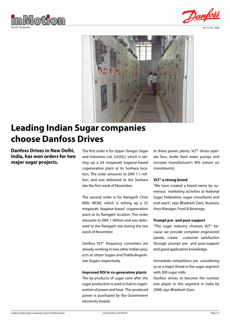
The first order is for Upper Ganges Sugar and Industries Ltd. (UGSIL), which is set-ting up a 24 megawatt bagasse-based cogeneration plant at its Seohara loca-tion. The order amounts to DKK 1.1 mil-lion, and was delivered to the Seohara site the first week of November.
The second order is for Ramgarh Chini Mills (RCM), which is setting up a 25 megawatt bagasse-based cogeneration plant at its Ramgarh location. This order amounts to DKK 1 Million and was deliv-ered to the Ramgarh site during the last week of November.
Danfoss VLT® frequency converters are already working in two other Indian proj-ects at Uttam Sugars and Prabhulingesh-war Sugars respectively.
Improved ROI in co-generation plantsThe by-products of sugar cane after the sugar production is used as fuel in cogen-eration of power and heat. The produced power is purchased by the Government electricity boards.
Danfoss Drives in New Delhi, India, has won orders for two major sugar projects.
Leading Indian Sugar companies choose Danfoss Drives
In these power plants, VLT® drives oper-ate fans, boiler feed water pumps and increase manufacturer’s ROI (return on investments).
VLT® a strong brand“We have created a brand name by nu-merous marketing activities at National Sugar Federation, sugar consultants and end users”, says Bhadresh Dani, Business Area Manager, Food & Beverage.
Prompt pre- and post-support“The sugar industry chooses VLT® be-cause we provide complete engineered panels, create customer satisfaction through prompt pre- and post-support and good application knowledge.
Immediate competitors are considering us as a major threat in the sugar segment with 300 sugar mills. Danfoss strives to become the number one player in this segment in India by 2008, says Bhadresh Dani.
www.Danfoss.com/Drives
The VLT® Newsletter
inMotionNo 16, Dec. 2006
Page 1/2High tech suture material for the medical industry in Korea and Japan
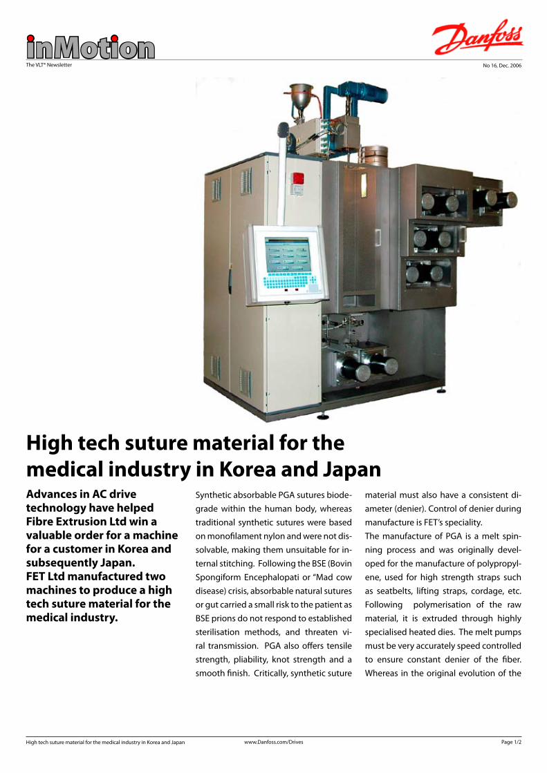
Synthetic absorbable PGA sutures biode-grade within the human body, whereas traditional synthetic sutures were based on monofilament nylon and were not dis-solvable, making them unsuitable for in-ternal stitching. Following the BSE (Bovin Spongiform Encephalopati or “Mad cow disease) crisis, absorbable natural sutures or gut carried a small risk to the patient as BSE prions do not respond to established sterilisation methods, and threaten vi-ral transmission. PGA also offers tensile strength, pliability, knot strength and a smooth finish. Critically, synthetic suture
Advances in AC drive technology have helped Fibre Extrusion Ltd win a valuable order for a machine for a customer in Korea and subsequently Japan. FET Ltd manufactured two machines to produce a high tech suture material for the medical industry.
High tech suture material for the medical industry in Korea and Japan
material must also have a consistent di-ameter (denier). Control of denier during manufacture is FET’s speciality.The manufacture of PGA is a melt spin-ning process and was originally devel-oped for the manufacture of polypropyl-ene, used for high strength straps such as seatbelts, lifting straps, cordage, etc. Following polymerisation of the raw material, it is extruded through highly specialised heated dies. The melt pumps must be very accurately speed controlled to ensure constant denier of the fiber. Whereas in the original evolution of the

www.Danfoss.com/Drives
The VLT® Newsletter
inMotion
machines, synchronous or synchronous reluctance motors were driven by stan-dard inverters, the more accurate vector control of modern drives enables stan-dard 1.5kW induction motors fitted with encoder feedback to be adopted.
High speed accuracy and stability are criticalPassing from the die, the fibre is air quenched to solidify and stabilise it be-fore it passes to a series of 4 pairs of heat-ed draw rolls, each pair of rolls driven by a single inverter drive. Here again high speed accuracy and stability are critical, as the accuracy of draw ratio between roll pairs imparts molecular orientation and governs the material denier. There is a final relaxation to condition the yarn before it passes to a wind-up section where the fibre is ‘laid on’ to a bobbin in
an accurately controlled pattern to en-sure a stable pack.In this application there were a total of nine VLT® AutomationDrives on each machine.3 x 7.5 kw, 2 x 5.5 kw, 2 x 2.2 kw and 2 at 0.37 kw. These were connected to a Danfoss Ethernet master module, which enables the machine to communicate remotely. The ability to offer high per-formance closed loop speed control, and an Ethernet solution was fundamental in securing the business. Global support played an important part in the decision process due to the location of the cus-tomer.
According to Managing Director Richard Slack “We selected the new Danfoss VLT® AutomationDrive for a number of rea-sons. In addition to the accurate vector
control, there are a number of features on the AutomationDrive that simplified their adoption and gave us confidenceto meet the demands. Not least of these is the ability to connect the drives on an Ethernet network, which enables us to interrogate the machine set-up remote-ly.
Well represented worldwideDanfoss is also well represented world-wide so service considerations for Korea and Japan were fully met. Mr. Slacvk says: “From the first evolution of these ma-chines almost 20 years ago, we’ve always relied upon our drive suppliers not only to supply first class products but also to provide a high level of consultancy dur-ing the development process. Danfoss again met that need in every regard.”
Page 2/2High tech suture material for the medical industry in Korea and Japan

www.Danfoss.com/Drives
The VLT® Newsletter
inMotionNo 16, Dec. 2006
Page 1/1VLT® quality preferred by Dutch dairy company
Danfoss quality won a project with the Dutch company Van Uitert for the Dutch dairy company Friesche Vlag. Van Uitert manufactures conveying and packaging systems, and until now, their preferred supplier of decentral drives was a Dan-foss competitor. Friesche Vlag, on the other hand, is a long-term Danfoss customer and there-fore prefers a Danfoss solution.
Van Uitert planned to offer the project about 200 geared motors and decentral drives from our competitor. However they would also give Danfoss a chance to offer a solution for both geared mo-tors and drives. Consequently Danfoss in the Netherlands decided to try to win the project.
Danfoss quality made the Dutch company Van Uitert win a project for the Dutch dairy company Friesche Vlag.
VLT® is now Van Uitert’s standard solution.
VLT® quality preferred by Dutch dairy companyVLT® - standard choice in the future.Danfoss’ offer was convincing and Van Uitert decided to place the order with Danfoss, but also to make Danfoss solu-tions the standard choice in the future.
The project was up against a very tight time schedule. The drives had to be sup-plied by the end of October, and product adaptations would make our decentral drives more suitable for this type of con-veyor. Additionally, Van Uitert had to get all drives up and running in a very short time.
Thanks to a very tight follow-up on all designs, excellent support and flexibility from all departments involved, we met the customer’s demand.

www.Danfoss.com/Drives
The VLT® Newsletter
inMotionNo 16, Dec. 2006
Page 1/1The VLT® Motion Control Tool now supports VLT® HVAC Drive.
Danfoss introduces an update of the set-up and configuration software MCT 10.
The new version 2.26, Build 512 now also supports the VLT® HVAC Drive suited for Building Controls. It is now possible to configure and programme the HVAC Drive using the software. MCT 10 allows the user to access the frequency convert-er via USB or RS 485-interface.
Also new is an optimized access to MCO 305, which is freely programmable for special control tasks or can be used for synchronisation, positioning and cam control.
MCT 10 now also supports VLT® HVAC Drive. Latest update is available on the Internet.
The VLT® Motion Control Tool now supports VLT® HVAC Drive
To simplify the adaptation of the VLT® fre-quency converters to the Danfoss Bauer gear motors, MCT 10 now comprises a database with all necessary motor data. This makes for easy commissioning of VLT® frequency converters used in com-bination with Danfoss Bauer gear motors – which saves time and thereby money. In order to facilitate the planning of es-pecially large-scale projects, MCT 10 now gives quicker access to these project da-tabases.
Find the new software on the internet here :
Software Download
(www.danfoss.com/BusinessAreas/DrivesSolutions/Softwaredownload)

www.Danfoss.com/Drives
The VLT® Newsletter
inMotionNo 16, Dec. 2006
Page 1/1New VLT® Ethernet Powerlink Option
Ethernet Powerlink represents the sec-ond generation of field-bus. It uses high bit rate of Industrial Ethernet, applying the full power of IT technologies to the automation world for the first time.Ethernet, when introduced in automa-tion, is still open and independent.Ethernet Powerlink provides high perfor-mance real-time and time synchroniza-tion features. Due to its CANopen-based communication models, network man-
The VLT® Ethernet Powerlink protocol uses standard Fast Ethernet, extended by specific scheduling mechanisms, for deterministic data transfer.
New VLT® Ethernet Powerlink Optionagement and device description, this model offers much more than just a fast communication network. This architec-ture provides all additional system fea-tures necessary for distributed automa-tion systems in a standardized manner. This makes it easy to provide integration of systems built up with devices from multiple manufacturers.
The perfect solution for: l Dynamic motion control applicationsl Material handlingl Synchronisation and positioning applications
Features Benefits
• Cycle-times down to 200us • meets toughest real-time demands
• High bandwidth Asynchronous IP data access • multi-purpose bus
• Jitter < 1us
• Velocity, position and marker synchronizing
• maximum performance and precise timing
• Integrated hub for daisy chaining • supports any network topology
• No proprietary ASICs needed• License free
• saving money
• Industry proven• Large installed base
• widely supported• available and widely deployed
• Plug-and-Play commissioning • easy to learn and use
• CANopen application layer • backwards compatibility
• Integrated safety technology • saves cabling and commissioning costs
www.Danfoss.com/Drives
The VLT® Newsletter
inMotionNo 16, Dec. 2006
Page 1/3New EU standard places more EMC responsibility with users and operators
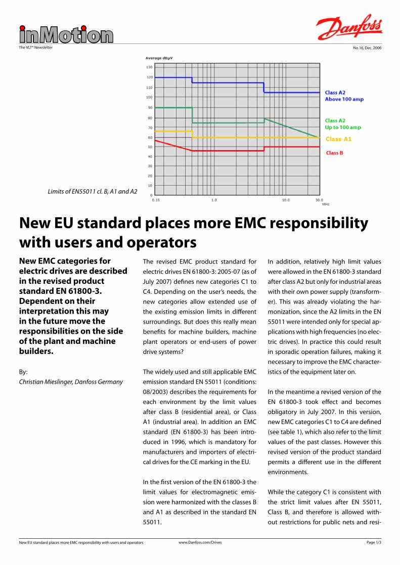
The revised EMC product standard for electric drives EN 61800-3: 2005-07 (as of July 2007) defines new categories C1 to C4. Depending on the user’s needs, the new categories allow extended use of the existing emission limits in different surroundings. But does this really mean benefits for machine builders, machine plant operators or end-users of power drive systems?
The widely used and still applicable EMC emission standard EN 55011 (conditions: 08/2003) describes the requirements for each environment by the limit values after class B (residential area), or Class A1 (industrial area). In addition an EMC standard (EN 61800-3) has been intro-duced in 1996, which is mandatory for manufacturers and importers of electri-cal drives for the CE marking in the EU.
In the first version of the EN 61800-3 the limit values for electromagnetic emis-sion were harmonized with the classes B and A1 as described in the standard EN 55011.
In addition, relatively high limit values were allowed in the EN 61800-3 standard after class A2 but only for industrial areas with their own power supply (transform-er). This was already violating the har-monization, since the A2 limits in the EN 55011 were intended only for special ap-plications with high frequencies (no elec-tric drives). In practice this could result in sporadic operation failures, making it necessary to improve the EMC character-istics of the equipment later on.
In the meantime a revised version of the EN 61800-3 took effect and becomes obligatory in July 2007. In this version, new EMC categories C1 to C4 are defined (see table 1), which also refer to the limit values of the past classes. However this revised version of the product standard permits a different use in the different environments. While the category C1 is consistent with the strict limit values after EN 55011, Class B, and therefore is allowed with-out restrictions for public nets and resi-
New EMC categories for electric drives are described in the revised product standard EN 61800-3.Dependent on their interpretation this may in the future move the responsibilities on the side of the plant and machine builders.
New EU standard places more EMC responsibility with users and operators
By: Christian Mieslinger, Danfoss Germany
Limits of EN55011 cl. B, A1 and A2
www.Danfoss.com/Drives
The VLT® Newsletter
inMotion
dential areas (1. Environment), the prod-uct standard now leaves the decision to the drives user whether it is appropriate to engage drives with EMC emissions of category C2 within this surrounding. The C2 limit values, however, correspond to those of the EN 55011, Class A1, which were, so far only permissible for industrial surroundings.
A similar situation is applicable in the case for installations in industrial environ-ments.Here the limit values clearly applies after class A1 according to EN 55011 (excep-tion: voltages > 1000V, rated currents above 400A or IT network supply).
The operator can now, according to the new product standard, also decide to permit drives that only fulfil the require-ments of category C3 (corresponding to EN 55011/class A2).
In both described cases it is mandatory to place a clear warning in the documenta-tion to inform about the increased dan-ger of EMC disturbance.
At first sight reduced EMC limit values ap-pear positive, leading to clearly reduced screening and filtering measures and by this reduced installation costs. Also drives
manufacturers in particular could benefit since they possibly could provide prod-ucts in higher environment classes but with cheaper EMC filter design.
But by this the decision over, and thus the responsibility for, employment rests explicitly on the operator of the machine and plant. This means, that in case of EMC problems he has to remove arising func-tional problems at his own expense.Or differently expressed: the manufactur-er of the drive system is only responsible for the adherence to limit values in accor-dance with the indicated C-category. For consequences cling only users and opera-tors.
Since the operator will have defined de-fault EMC values for individual compo-nents, the machine builder is however
responsible for the overall functioning of his plant. The situation becomes particu-larly difficult if components come from several suppliers.
In such controversies for EMC exami-nations the limit values are consulted anyway according to the environment standard EN55011. Even if the product standard is kept, other components might suffer from EMC emissions.
It can be expected that this may become even worse in future as more and more PLC and fieldbus functionalities in mod-ern controls and drive controllers will also lead to an increasing number of micropro-cessors with rising clock frequencies. This inevitably leads to more high frequency interference sources in the plants.
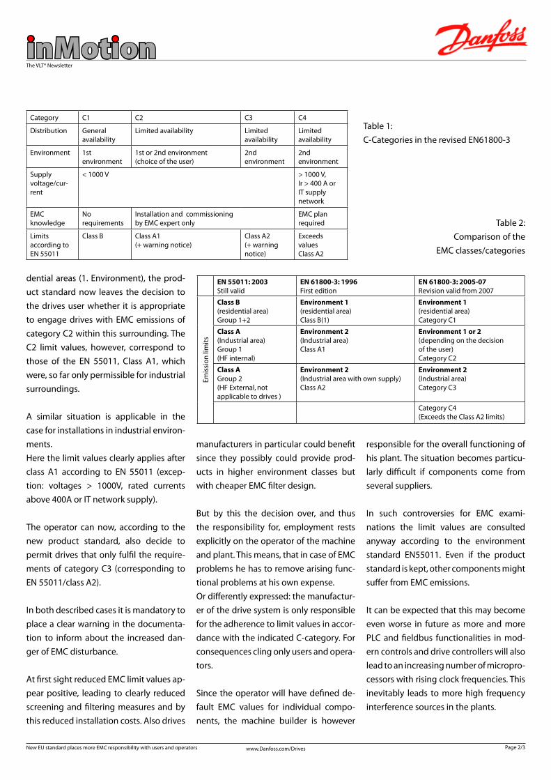
Category C1 C2 C3 C4
Distribution General availability
Limited availability Limited availability
Limited availability
Environment 1st environment
1st or 2nd environment (choice of the user)
2nd environment
2nd environment
Supply voltage/cur-rent
< 1000 V > 1000 V,Ir > 400 A orIT supply network
EMC knowledge
No requirements
Installation and commissioning by EMC expert only
EMC plan required
Limits according toEN 55011
Class B Class A1(+ warning notice)
Class A2(+ warning notice)
Exceeds valuesClass A2
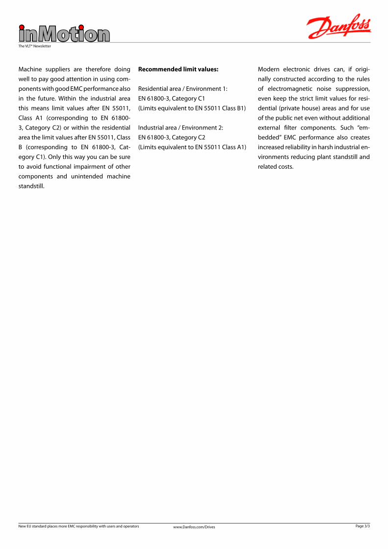
EN 55011: 2003Still valid
EN 61800-3: 1996First edition
EN 61800-3: 2005-07Revision valid from 2007
Emis
sio
n li
mit
s
Class B(residential area)Group 1+2
Environment 1(residential area)Class B(1)
Environment 1(residential area)Category C1
Class A(Industrial area)Group 1(HF internal)
Environment 2(Industrial area)Class A1
Environment 1 or 2(depending on the decisionof the user)Category C2
Class AGroup 2(HF External, not applicable to drives )
Environment 2(Industrial area with own supply)Class A2
Environment 2(Industrial area)Category C3
Category C4(Exceeds the Class A2 limits)
Table 1: C-Categories in the revised EN61800-3
Table 2: Comparison of the
EMC classes/categories
Page 2/3New EU standard places more EMC responsibility with users and operators
www.Danfoss.com/Drives
The VLT® Newsletter
inMotionMachine suppliers are therefore doing well to pay good attention in using com-ponents with good EMC performance also in the future. Within the industrial area this means limit values after EN 55011, Class A1 (corresponding to EN 61800-3, Category C2) or within the residential area the limit values after EN 55011, Class B (corresponding to EN 61800-3, Cat-egory C1). Only this way you can be sure to avoid functional impairment of other components and unintended machine standstill.
Recommended limit values:
Residential area / Environment 1: EN 61800-3, Category C1 (Limits equivalent to EN 55011 Class B1)
Industrial area / Environment 2: EN 61800-3, Category C2(Limits equivalent to EN 55011 Class A1)
Modern electronic drives can, if origi-nally constructed according to the rules of electromagnetic noise suppression, even keep the strict limit values for resi-dential (private house) areas and for use of the public net even without additional external filter components. Such “em-bedded” EMC performance also creates increased reliability in harsh industrial en-vironments reducing plant standstill and related costs.
Page 3/3New EU standard places more EMC responsibility with users and operators

www.Danfoss.com/Drives
The VLT® Newsletter
inMotionNo 16, Dec. 2006
Page 1/1Danfoss Brazil brings smiles to orphaned children
Danfoss Brazil is putting smiles on the faces of orphaned children at PIVI (in Por-tuguese Project to Improve Lives), which houses more than 90 children of all ages. Danfoss has set up a donation box in thereception for everyone to make contri-butions and so far has brought in several boxes of toys and clothing, as well as non-perishable food.The children and the project’s managers are grateful to all who have contributed so far.
Danfoss brought in several boxes of toys and clothing, as well as non-perishable food.
Danfoss Brazil brings smiles to orphaned children