Embed Size (px)
Citation preview

- 0 -
DAN04
DANTE PYRAMID FLAME PATIO HEATER
WARNING: FOR OUTDOOR USE ONLY
INSTRUCTION MANUAL

- 1 -
PLEASE KEEP THE MANUAL FOR FUTURE REFERENCE!
TABLE OF CONTENTS
Patio Heater Safety Warnings -------------------------------------------
Part List & Hardware -------------------------------------------------------
Exploded View ---------------------------------------------------------------
Patio Heater Assembly ----------------------------------------------------
Operating Instructions -----------------------------------------------------
Leak Testing ------------------------------------------------------------------
Gas Requirement -----------------------------------------------------------
Connecting To a Gas Cylinder -------------------------------------------
Important Safety Rules ----------------------------------------------------
Maintenance -----------------------------------------------------------------
Servicing ----------------------------------------------------------------------
Storage ------------------------------------------------------------------------
Troubleshooting--------------------------------------------------------------
Technical Data ---------------------------------------------------------------
Guarantee ---------------------------------------------------------------------
Discard -------------------------------------------------------------------------
PATIO HEATER SAFETY WARNINGSPLEASE READ THE INSTRUCTIONS CAREFULLY BEFORE INSTALLATION AND USE.
This appliance must be used outdoors or in a well ventilated area, and should not be installed or used indoors. Change the gas cylinder in a well ventilated area, away from any inflammation sources. The cylinder must be stored outdoors or in a well ventilated area. Storage this appliance indoors is permissible only if gas cylinder is disconnected and removed from the
appliance. Do not move this appliance when in operation, or after it has been turned off before the temperature has cooled
down. Do not attempt to alter the appliance in any manner. Do not paint the radiant screen, control panel or reflector. Do not obstruct the ventilation holes of the cylinder housing. The appliance must be installed and gas cylinder stored in accordance with local gas fitting regulations. Shut off the valve at the gas cylinder or the regulator before moving the appliance. Repairs should be done by a qualified person. In case of violent wind, particular attention must be taken against tilting of the appliance. Check that the regulator seal is correctly fitted and able to fulfil its function. Close the gas supply at the valve of the gas cylinder or the regulator after use. Do not use this appliance until all connections have been leak tested.
1-2
3
4
4-8
9
10
10
10
11
11
12
12
13
14
14
14

- 2 -
In the event of gas leakage, the appliance shall not be used or if alight, the gas supply shall be shut off and theappliance shall be investigated and rectified before it is used again.
Checking the tubing or the flexible hose per month and each time the cylinder is changed. The tubing or the flexible hose must be changed within the prescribed intervals or within one year. The hose assembly must be replaced prior to the appliance being put into operation if there is evidence of
excessive abrasion or wear, or if the hose is damaged, and that the replacement hose assembly shall be thatspecified by the manufacturer.
The heater should be inspected before use and at least annually by a qualified service person. More frequentcleaning may be required as necessary. It is imperative that control compartment, burners and circulating airpassageways of the appliance be kept clean.
Shut off and check heater immediately if any of the following conditions exist: The smell of gas in conjunction with extreme yellow tipping of the burner flames. Heater does not reach a proper temperature. A temperature less than 5℃ will cause restricted heat flow and
the appliance will not work properly. The appliance starts making popping noises during use (a slight popping noise is normal when the
appliance is extinguished). The regulator & hose assembly must be located out of pathways where people may trip over it or in area where
the hose will not be subject to accidental damage. Any guard or other protective device removed for servicing the heater must be replaced before operating the
heater. Children and adults should be warned of the hazards of high surface temperatures and should stay away to
avoid burns or clothing ignition. Young children and pets should be carefully supervised when they are in the area of the heater. Clothing or other flammable materials should not be hung from the appliance, or placed on or near the
appliance. Do not place articles on or against this appliance. Certain material or items when stored under or near this
appliance will be subjected to radiant heat and could be seriously damaged. Do not use or store flammable materials near this appliance. Do not spray aerosols in the vicinity of this appliance while it is in operation. Always maintain at least 0.9m clearance from combustible materials. Always position the appliance on a firm level surface. An amply ventilated area must have a minimum of 25% of
the surface area open. The surface area is the sum of the walls surface.

- 3 -
PATIO HEATER PART LIST
PART # PART NAME PICTURE QTY
A REFLECTOR 1
B FLAME SCREEN 1
C MESH GUARD - UPPER 4
D MESH GUARD - LOWER 4
E SUPPORT BAR - UPPER 4
F SUPPORT BAR - LOWER 4
G GLASS TUBE 2
HCONNECTOROption 1: Glass Tube ConnectorOption 2: Stainless Steel Connector (Option 1) or (Option 2)
1
I RUBBER RING 1
J BURNER ASSEMBLY
K TANK HOUSING ASSEMBLY 1
L CHAIN (ASSEMBLED WITH DOOR) 1
HARDWARE
PART # PART NAME PICTURE QTY DESCRIPTION
AA M5 CAP NUT 4TO CONNECT REFLECTOR ANDFLAME SCREEN
BBSTANDARDSCREWS & WASHER
12M5 X 8 SCREW & M5 WASHERTO FIX BURNER ASSEMBLY ONTHE TANK HOUSING ASSEMBLY.

- 4 -
EXPLODED VIEW

- 5 -
PATIO HEATER ASSEMBLYASSEMBLY INSTRUCTIONS
List of Required Tools: Philip Screwdriver Leak Detection Solution one part detergent and three parts water Assemble all nuts and bolts loosely at first. Tighten all connections after completion of assembly.
This eases your work and increase the stability of the appliance. Before assembly, make sure all packing material and any transmit protection must be removed. Small deviations in equipment may occur. This is no lack of quality but subject to improvements. If any part is missing or damaged, do not attempt to assembly this product, Contact customer service for
replacement parts. Assembly should be performed on a flat, level, non-abrasive surface. ESTIMATED ASSEMBLY TIME: 45 minutes.
STEP 1: Put down tank housing assembly (K) as shownabove. Take down the door and take out all parts.
STEP 2: Keep the burner with the igniter side up. Fixthe burner assembly (J) to tank housing using 4pcs M5Screws and Washers (BB).
STEP 3: Unscrew 2pcs M5 screws and washers (BB) preassembled in Support Bar – Lower (F).Insert upper Support Bar (E) to lower Support Bar (F) and fix the connection using 2pcs screws and washers (BB).Repeat this step and connect other 3 sets support bars.

- 6 -
STEP 4: Attach Flame Screen (B) to the top of upper Support Bar (E) and fix the connection using 2pcs M5 screwsand washers (See FigureⅠ, Ⅱ).Repeat this step and connect Flame Screen (B) to other 3 sets upper Support Bars. (See Figure Ⅲ, Ⅳ)
STEP 5: Place Reflector (A) on the Flame Screen (B) andfix the connection using 4pcs M5 CAP NUT (AA).
STEP 6: Unscrew 8pcs M5 Screws and Washers (BB) preassembled on top of tank housing assembly (K).Place the lower support Bars to top of tank housing assembly. Make sure match the top ends of tank housingassembly with the slot of lower Support Bar. Match the threaded hole and fix each connection with 2pcs M5Screws and Washers (BB)
- 7 -
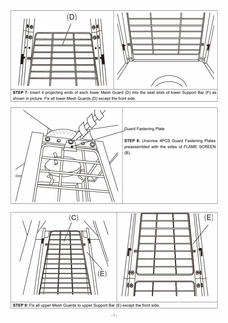
STEP 7: Insert 4 projecting ends of each lower Mesh Guard (D) into the seat slots of lower Support Bar (F) asshown in picture. Fix all lower Mesh Guards (D) except the front side.
Guard Fastening Plate
STEP 8: Unscrew 4PCS Guard Fastening Platespreassembled with the sides of FLAME SCREEN(B).
STEP 9: Fix all upper Mesh Guards to upper Support Bar (E) except the front side.

- 8 -
STEP 10: Put Rubber Ring (I) around the burner hole. Connect 2pcs Glass Tubes (G) with Connector (H). Hold thewhole glass tube assembly carefully. Insert the top end into the bottom hole of Flame Screen as much as possibleKeep the whole glass tube assembly vertically and sit it on Rubber Ring (I).
NOTE: GLASS TUBES ARE FRAGILE, HANDLE WITH GLASS TUBES CAREFULLY AND SLOWLY!
STEP 11: Assemble Lower Mesh Guard (D) andUpper Mesh Guard (C) in the front. Fix 4pcs GuardFastening Plates to keep Upper Mesh Guard (C)firmly in place.
STEP 12: Insert the feet of door into the bottom slots.Attach the Chain (L) to the hook of Burner Assembly (J)and close the door.

- 9 -
OPERATING INSTRUCTIONSBEFORE FIRST USE AND AFTER EVERY GAS CYLINDER CHANGE, GAS DELIVERY SYSTEM MUST BEPURGED OF AIR BEFORE IGNITING! TO DO THIS, TURN THE CONTROL KNOB ANTI-CLOCKWISE TO THEPILOT SETTING. PRESS KNOB IN AND HOLD FOR 3 MINUTES BEFORE ATTEMPTING IGNITION.
BATTERY REPLACMENTRemove impulse ignition cap from Burner Assembly (J) by turning cap counterclockwise. Install 1 AAA battery.Negative end of battery goes in first, then replace impulse ignition cap by turning cap clockwise.
TO LIGHT THE PILOT Check all connections prior to each use. Turn on main gas supply at source. Press to turn control knob anti-clockwise to PILOT,
see right photo. Hold knob depressed, press IGNITION button
repeatedly until pilot flame is lit, then continue tohold the knob depressed for 10 seconds until thepilot remains it after releasing knob.
If pilot fails to ignite or alight, press to turn knobclockwise to OFF and repeat.
TO LIGHT THE PATIO HEATER The pilot should be lit and the knob set to PILOT. Hold knob depressed gently and turn anti-clockwise to LOW. When mesh glows lit, turn knob clockwise from Low to HIGH as needed.Note: The burner may be noisy when initially turned on. To eliminate excessive noise from the burner, turnthe control knob to the pilot position. Then turn the knob to the level of heat desired.
RE-LIGHTING Turn Control Knob to OFF. Wait at least 5 minutes, to let gas dissipate, before attempting to re-light pilot. Repeat the “Lighting” steps.
TO EXTINGUISH Hold knob depressed & turn the knob clockwise to 'OFF' Close the valve of the gas cylinder or the regulator after use. Close the gas bottle and allow this appliance to cool before moving the appliance.Note: After use, some discoloration of the emitter screen is normal. Close regulator after use, allow theappliance to cool before moving.

- 10 -
LEAK TESTINGNEVER USE A NAKED FLAME TO CHECK FOR LEAKS.NEVER LEAK TEST WHILE SMOKING.The gas connections on this appliance are leak tested at the factory prior toshipment.This appliance needs to be periodically checked for leaks and an immediatecheck is required if the smell of gas is detected. Make a soap solution using 1 part of liquid dish-washing soap to 3 parts
water. The soap solution can be applied with a soap bottle, brush, or ragto the leak tested points shown in the figure above.
The valve of the gas cylinder should be in the OFF position at this point ofthe leak test. Once the soapy solution is applied to the gas connections,the valve of the gas cylinder needs to be turned to the ON position.
Soap bubbles will begin to form in the soapy solution if a leak is present. In case of a leak, turn off the gas supply. Tighten any leaking fittings, then
turn the gas supply on and recheck.
GAS REQUIREMENTS The appliance must use an EN12864 or EN16129 approved gas regulator and CE approved gas hose with a
length of 50cm (BS3212 and EN1763-1). Choose the proper regulator according to outlet pressure in thetechnical table in page 14.You will need to purchase suitable gas hose and regulator from your local gas dealer if the appliance does notinclude gas hose and regulator.
Never use a gas cylinder with a damaged body, valve, collar, or foot ring. A dented or rusty gas tank may behazardous and should be checked out by a gas supplier.
Never connect this appliance to an unregulated gas source. When the appliance is not in use, turn the gas cylinder OFF. Always perform a leak test on gas connections whenever a cylinder is connected. If bubbles form in the leak test
solution, do not use. Never use a flame to test for leaks.
CONNECTING TO A GAS CYLINDER Recommended to use max 15 kg or smaller gas cylinder (maximum height 65cm) refer to your gas supplier for
suitable gas cylinder. Approved gas regulator is used according to appliances categories and countries listed in data plate. Approved
flexible hose would be changed when the national conditions require it. Assembly of the tubing must be conducted by some qualified tuber of destination countries. Only change gas cylinders outdoors or in a well ventilated area away from naked flames and any other source of
ignition (candle, cigarettes, other flame producing appliance….). The gas cylinder must always be used in an upright position. Close the heater control knob by turning fully clockwise. Close the gas cylinder tap and then attach the regulator onto the gas cylinder. Tighten all connections firmly and with a spanner where appropriate. The cylinder should be located on the
cylinder base. Check for leaks at all joints using soapy water. If a leak is found, tighten the joint and then re-test.
Leak Test Point①②③
- 11 -
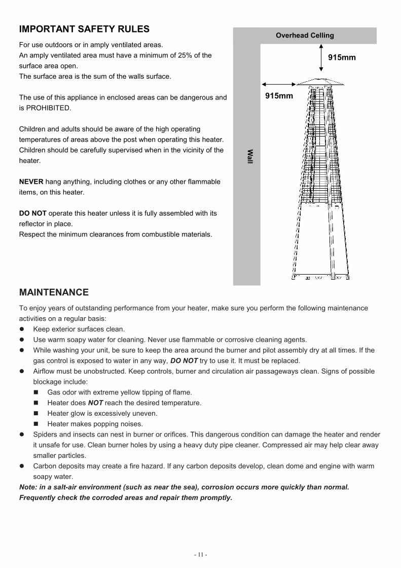
IMPORTANT SAFETY RULESFor use outdoors or in amply ventilated areas.An amply ventilated area must have a minimum of 25% of thesurface area open.The surface area is the sum of the walls surface.
The use of this appliance in enclosed areas can be dangerous andis PROHIBITED.
Children and adults should be aware of the high operatingtemperatures of areas above the post when operating this heater.Children should be carefully supervised when in the vicinity of theheater.
NEVER hang anything, including clothes or any other flammableitems, on this heater.
DO NOT operate this heater unless it is fully assembled with itsreflector in place.Respect the minimum clearances from combustible materials.
MAINTENANCETo enjoy years of outstanding performance from your heater, make sure you perform the following maintenanceactivities on a regular basis: Keep exterior surfaces clean. Use warm soapy water for cleaning. Never use flammable or corrosive cleaning agents. While washing your unit, be sure to keep the area around the burner and pilot assembly dry at all times. If the
gas control is exposed to water in any way, DO NOT try to use it. It must be replaced. Airflow must be unobstructed. Keep controls, burner and circulation air passageways clean. Signs of possible
blockage include: Gas odor with extreme yellow tipping of flame. Heater does NOT reach the desired temperature. Heater glow is excessively uneven. Heater makes popping noises.
Spiders and insects can nest in burner or orifices. This dangerous condition can damage the heater and renderit unsafe for use. Clean burner holes by using a heavy duty pipe cleaner. Compressed air may help clear awaysmaller particles.
Carbon deposits may create a fire hazard. If any carbon deposits develop, clean dome and engine with warmsoapy water.
Note: in a salt-air environment (such as near the sea), corrosion occurs more quickly than normal.Frequently check the corroded areas and repair them promptly.
Overhead Celling
Wall
915mm
915mm
- 12 -
SERVICING Please consult your local dealer for servicing this appliance and replacement of its parts. The servicing of the
appliance shall be carried out only by authorised personnel. Caution: do not use unauthorized parts or components for this appliance, only use original equipment
replacement parts and components. The use of unauthorized parts or components will void the warranty andcan create an unsafe condition.
STORAGEThere is no limitation on the storage of the appliance indoors provided that the cylinder is removed from theappliance.Between uses: Turn control knob OFF Turn gas cylinder OFFStore heater upright in an area sheltered from direct contact with inclement weather (such as rain, sleet, hail, snow,dust and debris).If desired, cover to protect exterior surfaces and to prevent build up in air passages.Note: Wait until heater is cool before covering.
During periods of extended inactivity or when transporting: Turn control knob OFF. Disconnect gas cylinder and move to a secure, well ventilated location outdoors. DO NOT store in a location that
will exceed 50°C.Store heater upright in an area sheltered from direct contact with inclement weather (such as rain, sleet, hail, snow,dust and debris).If desired, cover heater to protect exterior surfaces and to prevent build up in air passages.Note: Wait until heater is cool before covering

- 13 -
TROUBLESHOOTING
IF THE PROBLEM IS: AND THIS CONDITION EXISTS: THEN DO THIS:
Pilot won’t light
Cylinder valve is closed Open valveBlockage in orifice or pilot tube Clean or replace orifice or pilot tube
Air in the gas lineOpen gas line and bleed it (pressingcontrol knob in) for not more than1-2 minutes or until you smell gas
Low gas pressure Gas cylinder low or empty
Igniter failsUse match to light pilot, and obtain newigniter and replace. ( See below pictures)
Pilot won’t stay lit
Dirt build up around pilot Clean dirt from around pilotConnection between gas valve and pilotassembly is loose
Tighten connection and performleak test
Bad thermocouple Replace thermocouple
Burner won’t lightGas pressure is low Replace gas cylinderBlockage in orifice Clear blockageControl knob is not in "ON" position Turn control knob to "ON" position
Burner flame is lowNote: Do not operateheater below5℃(40°F)
Gas pressure is low Replace gas cylinderOutdoor temperature is greater than 5℃(40°F)and tank is less than 25% full
Replace gas cylinder
Supply hose is bent or kinkedStraighten hose and perform leak test onhose
Control knob is fully " ON"Turn control knob to "OFF", let it cool toroom temperature and check burner andorifices for blockage
Emitter glowsunevenNote: Bottom 2.5cm ofemitter normally doesnot normally glow
Gas pressure is low Replace gas cylinder
Base is not on a level surface Place heater on a level surface
Heater not level Level heater
Carbon build-up Dirt or film on reflector and emitter Clean reflector and emitter
Thick black smoke Blockage in burner
Turn control knob to "OFF", let it cool toroom temperature and removeblockage and clean burner inside andoutside.

- 14 -
TECHNICAL DATA
GUARANTEEAny defect affecting the functionality of the appliance which becomes apparent within one year of itspurchase will be corrected by free repair or replacement provided that it has been used andmaintained in accordance with the instructions and has not been abused or misused in any way. Yourstatutory rights are not affected. If it’s under guarantee, state where and when it was bought, andinclude proof of purchase (e.g. till receipt).In line with our policy of continuous product development we reserve the right to change product,packaging and documentation specifications without notice.
DISCARDAt the end of the life of the appliance, please cast of the appliance according to the on that momentapplying regulations and guidelines.
IN THE EVENT OF ANY PROBLEM, PLEASE ALWAYS CONSULT YOUR LOCAL DEALER.
LeisureGrow Group, LeisureGrow Products LimitedDewmead Farm, New Inn Road, Hinxworth, Hertfordshire, SG7 5HG, United Kingdom
TEL: +44 (0) 1462 744 500
Model: H1501 & H1502 & H1501A & H1502A & H1505 & H1507 & H1510Heat input ∑Qn(Hs)=11.2kWConsumption: 815g/hPIN: 0063CL7070
Country CodeCH-ES-FR-GB-GR- IE-IT-PT
BE-CY-CZ-DK-EE-FI-GR-IT-LT-LV-MT-NL-NO-SE-SI-SK-BG-RO-TR
AT-CH-DE PLCZ-FR-GB-GR-IE-PT
AT-CH-DE-NL
Gas Category I3+(28-30/37) I3B/P(30) I3B/P(50) I3B/P(37) I3P(37) I3P(50)
Type of Gas Butane PropaneButane/Propane / Mixture
Butane/Propane /Mixture
Butane/Propane/ Mixture
Propane Propane
Gas pressure28-30mbar
37mbar 30mbar 50mbar 37mbar 37mbar 50mbar
Injector Marking 1.6 1.6 1.4 1.5 1.6 1.5
WarningRead the instructions before using this appliance.The appliance must be installed in accordance with instructions and local regulations.The use of this appliance in enclosed areas can be dangerous and is PROHIBITED.For use outdoors or in amply ventilated areas.An amply ventilated area must have a minimum of 25% of the surface area open.The surface area is the sum of the walls surface.
0063


![Divina Commedia di Dante: Inferno - sapili.org fileDivina Commedia di Dante: Inferno by Dante Alighieri August, 1997 [Etext #997] The Project Gutenberg Etext "Divina Commedia di Dante:](https://img.pdfslide.us/doc/110x75/5e17a4c8f70c466de80c67e9/divina-commedia-di-dante-inferno-commedia-di-dante-inferno-by-dante-alighieri.jpg)

![Divina Commedia di Dante: Purgatorio · Divina Commedia di Dante: Purgatorio by Dante Alighieri August, 1997 [Etext #1010] Project Gutenberg's Etext "Divina Commedia di Dante: Purgatorio"](https://img.pdfslide.us/doc/110x75/5f9fe7e2b852aa749d7322dc/divina-commedia-di-dante-purgatorio-divina-commedia-di-dante-purgatorio-by-dante.jpg)