Embed Size (px)
Citation preview
23© Crown copyright 2014
AAIB Bulletin: 10/2014 EC-LTF EW/C2014/03/01
ACCIDENT
Aircraft Type and Registration: BD-700-1A10 Global 6000, EC-LTF
No & Type of Engines: 2 Rolls Royce BR710A2-20 turbofan engines
Year of Manufacture: 2011
Date & Time (UTC): 6 March 2014 at 1858 hrs
Location: Prestwick Airport, Scotland
Type of Flight: Commercial Air Transport (Passenger)
Persons on Board: Crew - 4 Passengers - 2
Injuries: Crew - None Passengers - None
Nature of Damage: Damage to right wingtip, aileron, flap track fairing and slat
Commander’s Licence: Airline Transport Pilot’s Licence
Commander’s Age: 46
Commander’s Flying Experience: 8,000 hours (of which 1,400 were on type) Last 90 days - 30 hours (all on type) Last 28 days - 20 hours (all on type) Information Source: AAIB Field Investigation
Synopsis
The right wing touched the runway while landing at night in a crosswind. The technique employed during the landing was different from that recommended in training material published by the manufacturer. Furthermore, the information in the training material about crosswind landings, and data on reduced wingtip clearance with increasing pitch attitude, had not been incorporated into the Airplane Flight Manual (AFM ) or the Flight Crew Operating Manual (FCOM).
The pilot flying (PF) was looking through a Head-Up Display (HUD) and his view of the runway may have been impeded because the symbols on the HUD screen were set too bright.
While the investigation was underway, another operator’s Global 6000 (CS-GLB) struck a wingtip during a night-time, crosswind landing at Luton Airport. The landing technique employed on CS-GLB shared certain similarities with EC-LTF.
Following these two accidents several safety actions were taken, including amendment of the FCOM to include the Manufacturer’s recommended technique when landing with a crosswind.
24© Crown copyright 2014
AAIB Bulletin: 10/2014 EC-LTF EW/C2014/03/01
History of the flight
The crew of EC-LTF, consisting of a commander and co-pilot, reported for duty at Barajas Airport, Madrid at 1515 hrs for a flight to Prestwick Airport. A training captain, conducting annual line checks on the pilots, occupied the jump seat.
The co-pilot obtained the ATIS information for Prestwick at 1849 hrs. It reported a surface wind from 190º at 16 kt, 10 km visibility in slight rain, scattered cloud at 1,000 ft aal, broken cloud at 2,000 ft aal, temperature 10ºC, dew point 9ºC, and QNH 1009 hPa. Runway 12, with an LDA of 2,743 m, was reported to be wet.
The flight proceeded without incident until the commander, who was PF, started the approach at night to Runway 12 at Prestwick. The localiser was captured at a range of 7 nm while at an altitude of 2,000 ft amsl. Prior to glideslope capture, the crew observed that the wind calculated by the onboard systems was 90º from the right at 35 kt. The autothrottle was engaged throughout the approach and the autopilot was used until the commander disengaged it at 400 ft agl1. There was a HUD fitted above the left glareshield and this was used by the commander, in accordance with standard practice on all approaches.
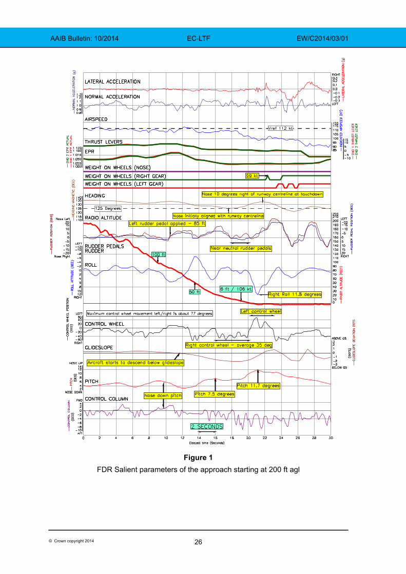
The VREF for the flap 30 landing was 112 KIAS and, with no gusts reported, was used as the target speed for the approach. When cleared to land, the aircraft was passed a wind from 190º at 12 kt which gave a crosswind component of approximately 11 kt. No further wind reports were passed during the approach and the wind speed shown on the aircraft’s instruments decreased as the aircraft descended. Passing 1,000 ft agl, the indicated crosswind had reduced to 25 kt and the pilots then had visual contact with the runway. At about the same time, the airspeed reduced to 107 KIAS (VREF minus 5 KIAS), and the commander briefly increased the target airspeed by 3 KIAS to 115 KIAS before resetting it to 112 KIAS (VREF). The autopilot was disengaged at 400 ft agl and the commander continued to compensate for the crosswind by pointing the aircraft’s nose to the right of centreline.
At approximately 100 ft agl a nose-down control column input caused the rate of descent to increase and the aircraft deviated below the glideslope. A right wing-down attitude began to develop and, at 85 ft agl, when the aircraft was about 330 m from the displaced threshold, left rudder was applied. In response the aircraft’s nose started to align towards the runway centreline and the aircraft rolled quickly left. The commander reacted to what he believed to be a gust of wind by making a control wheel input to the right. He briefly centred the rudder pedals before re-applying left rudder. At the same time, passing 50 ft agl, he commenced a flare by pitching to about 7.5º nose-up. The wings were then held in a near level attitude which required an average control wheel input of 35º to the right but with the rudder pedals almost neutral. This attitude was maintained for approximately 4 seconds and the nose of the aircraft began to yaw to the right. At 6 ft agl, the airspeed had decayed to 106 KIAS (VREF minus 6 KIAS).
Footnote1 For the purposes of this report the term agl refers to altitude above the reference ground level at the touchdown point.
25© Crown copyright 2014
AAIB Bulletin: 10/2014 EC-LTF EW/C2014/03/01
The commander increased the flare by pitching the nose quickly from about 7.5º to about 11.7º. The aircraft then started to roll right rapidly, so the commander reacted by moving the control wheel to about 50º to the left but the aircraft continued rolling right, reaching 11.8º before responding. In this nose-high attitude, the right wing contacted the runway, although the crew were unaware of the wing strike. Shortly afterwards the right main gear compressed with the right wing 7º down, at an airspeed of 99 KIAS (VREF minus 13 KIAS). The aircraft then rolled left before rolling right again and landed left of centreline with about 3.5º right wing down.
The pilots taxied the aircraft to the terminal where the passengers disembarked. The training captain then sat in the cabin while the aircraft was taxied to an overnight parking position and the two operating pilots discussed the landing and the use of the HUD.
A tug driver, working on another aircraft, reported that he had seen sparks from the vicinity of the aircraft when it landed. A subsequent check of the runway revealed two parallel grey marks on the surface of the tarmac, to the right of the centreline and between the displaced threshold and the usual touchdown point. An inspection of the aircraft revealed damage on the right wing.
FDR data was available for the entire flight, with the CVR audio record commencing prior to the approach and ending as the aircraft was shutdown at its overnight parking position. Salient parameters from the FDR, shown in Figure 1, included radio altitude, airspeed, pitch and roll2 attitude, control wheel3, control column and rudder pedal position4.
Aircraft description and damage
The aircraft is a long range business jet designed to carry up to 16 passengers and is a later variant of the Global Express. It is 30.3 m long and has a wingspan of 28.7 m. It can operate at M 0.89 and has a 35° swept wing. The aircraft has a digital glass cockpit design, with four large LCD displays. Data taken from the commander’s flight instruments are displayed on a HUD, which is rotated down from its stowed position in the ceiling panel above the left windscreen for use. The co-pilot’s position is not fitted with a HUD.
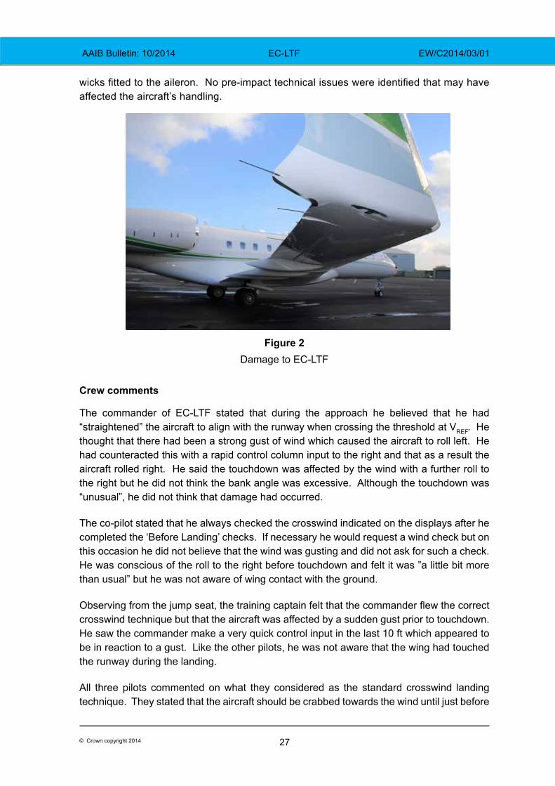
During the accident the aircraft suffered damage consistent with the right wing touching the runway surface at various points across its structure. The composite wingtip had been abraded in three positions, the heaviest contact having worn through the skin exposing the aluminium wing structure beneath. The damage to the rear of the wingtip extended onto the corner of the wing trailing edge. As the flaps and slats had been extended at touch down, the corner of the leading edge slat had been planed flat, as had the rear tip of the outboard flap track fairing. There was also damage to the outboard trailing edge of the aileron and static wick mounts, along with the loss of the two furthest outboard static
Footnote2 Roll was recorded four times per second.3 Control wheel was recorded sixteen times per second and the maximum control wheel movement left and right was about 77°.4 Rudder pedals were recorded at 16 times per second.
26© Crown copyright 2014
AAIB Bulletin: 10/2014 EC-LTF EW/C2014/03/01
Figure 1FDR Salient parameters of the approach starting at 200 ft agl
27© Crown copyright 2014
AAIB Bulletin: 10/2014 EC-LTF EW/C2014/03/01
wicks fitted to the aileron. No pre-impact technical issues were identified that may have affected the aircraft’s handling.
Figure 2Damage to EC-LTF
Crew comments
The commander of EC-LTF stated that during the approach he believed that he had “straightened” the aircraft to align with the runway when crossing the threshold at VREF. He thought that there had been a strong gust of wind which caused the aircraft to roll left. He had counteracted this with a rapid control column input to the right and that as a result the aircraft rolled right. He said the touchdown was affected by the wind with a further roll to the right but he did not think the bank angle was excessive. Although the touchdown was “unusual”, he did not think that damage had occurred.
The co-pilot stated that he always checked the crosswind indicated on the displays after he completed the ‘Before Landing’ checks. If necessary he would request a wind check but on this occasion he did not believe that the wind was gusting and did not ask for such a check. He was conscious of the roll to the right before touchdown and felt it was ”a little bit more than usual” but he was not aware of wing contact with the ground.
Observing from the jump seat, the training captain felt that the commander flew the correct crosswind technique but that the aircraft was affected by a sudden gust prior to touchdown. He saw the commander make a very quick control input in the last 10 ft which appeared to be in reaction to a gust. Like the other pilots, he was not aware that the wing had touched the runway during the landing.
All three pilots commented on what they considered as the standard crosswind landing technique. They stated that the aircraft should be crabbed towards the wind until just before
28© Crown copyright 2014
AAIB Bulletin: 10/2014 EC-LTF EW/C2014/03/01
touchdown. The rudder would then be used to align the aircraft with the runway, while an aileron input would be needed to keep the wings level.
While the aircraft was taxied to the overnight parking position, the commander commented about the HUD screen, in that it produced a bright green glow which had disorientated him. He said that the screen acted a bit like a mirror and had impeded his view of the runway and that in future he would not use the HUD at night in windy conditions.
Later he stated that he was comfortable using the HUD but that at night, in good weather conditions, it may become difficult to see some of the symbols on the HUD when there are bright lights in the vicinity of the runway. If the HUD brightness is turned up to counteract this, the effect can be to flood the screen with green light from the symbology. It may then be difficult to discern the runway and its immediate surroundings through the screen.
Prestwick surface wind
The surface wind (from 190º at 16 kt), quoted on the Prestwick ATIS was derived from an anemometer positioned on the eastern side of the airfield, in the vicinity of the touchdown zone for Runway 30. When the landing clearance was given, the crew were informed that the wind was from 190º at 12 kt. This information came from another anemometer, positioned on the western side of the airfield, close to the touchdown zone for Runway 12. An unofficial observation made by ATC personnel was that the wind velocity indicated from the western side of the airfield was usually a few knots less than that from the eastern side with a southerly wind direction.
During the aircraft’s approach the indications available to ATC were that the wind velocity remained steady, hence no additional wind checks were given on the radio.
EC-LTF operator’s manuals
The AFM stated that the maximum demonstrated crosswind component for takeoff and landing was 29 kt. This was not considered to be limiting when landing and there was no specific crosswind limit relating to use of the HUD for a Category 1 ILS approach.
The FCOM stated that the final approach speed should be VREF for the flap setting, plus half of any gust factor up to a maximum of 10 kt. However, the Operations Manual (OM) Part B stated that the approach speed should be VREF + 5 kt, plus any gust factor. No guidance concerning the crosswind landing technique was provided in the AFM, the FCOM or the OM.
The HUD, for use by the pilot in the left seat only, had been installed in EC-LTF since delivery. The AFM indicated that the HUD could be used for approaches, go-arounds and landings by day or night in VMC and IMC. The OM Part B, which was mostly written in Spanish, had not been updated to reflect the aircraft’s entry to service. It included a note that operational approval for the HUD was ‘pending’. A technical description of the HUD was provided in the FCOM but no advice was offered as to how this equipment might be best used by pilots.
29© Crown copyright 2014
AAIB Bulletin: 10/2014 EC-LTF EW/C2014/03/01
Manufacturer’s guidance and comments
The manufacturer produced an Operations Reference Manual (ORM) and a Pilot Training Guide for the Global 6000. These amplified the information provided in the AFM and the FCOM but they did not form part of the operator’s documentation. The crew had online access to the ORM and the Pilot Training Guide and they were expected to refer to them for recurrent simulator training.
The ORM stated: ‘Increased airspeeds above VREF may be required upon encountering turbulence, strong crosswinds or gusts,’ and the manual then mentioned the same procedure that was given in the FCOM for adjusting VREF ‘if the reported wind contains a gust’. The manufacturer subsequently stated that the information in the ORM was not correct and the speed increments above VREF were only required in the event of gusts. The manufacturer clarified that the ORM was not an ‘approved airplane manual’5 and was never intended to be used as a flight manual. Unlike the AFM and the FCOM, the ORM is not updated regularly so copies held by flight crew could become out of date.
The manufacturer also explained that for the Global aircraft the VREF is calculated based on VSMIN
6 methodology rather than VSR7. For aircraft that adopt fully reduced reference speeds
based on VSR methodology, VREF would normally equate to 1.23 x VSR and a significant portion of the certification programme for the Global Express (from which the Global 6000 was developed), was flown with a VREF equating to 1.23 x VSR. However, in agreement with Transport Canada, the manufacturer subsequently reverted to the more conservative VSMIN methodology for defining operating speeds and VREF was calculated as 1.326 x VSMIN. Consequently the VREF used for Global aircraft is between 6 and 8 KIAS greater than it would be if it had been calculated using the 1.23 x VSR formula.
The manufacturer also provided clarification on the effect of speed decay of VREF minus 13 KIAS prior to touchdown. For operational landings8, the speed decay after the initiation of the landing flare is not expected to exceed 4% of VREF. (With a VREF of 112 KIAS this would equate to 107.5 KIAS.) As far as roll control was concerned, the manufacturer stated that because the dynamic pressure at 99 KIAS is some 20% lower than at 112 KIAS, roll control power would diminish by about 6% at a control wheel angle of 50º but this would not compromise the ability to control the aircraft in roll. During certification tests an aircraft that was heavier than EC-LTF showed good lateral controllability at 100 KIAS in a full rudder sideslip.
Performance calculations for the Global aircraft were based on thrust being reduced to idle as the aircraft passed over the threshold at 50 ft with an airspeed of VREF and on the correct glide path. The instructions in the FCOM for a normal landing was that the thrust levers should move to idle at or below 50 ft agl and that aircraft attitude should be maintained until ‘close to the runway’ when the pilot should ‘Perform partial flare, and touchdown without Footnote5 See Safety actions.6 VSMIN is the non g-corrected stick pusher activation speed.7 VSR is defined as the reference stall speed of an aircraft at 1g and VSR = VS1G.8 Operational landings are those that are not made under test conditions.
30© Crown copyright 2014
AAIB Bulletin: 10/2014 EC-LTF EW/C2014/03/01
holding off’. The ORM noted that the flare should normally commence at approximately 30 ft above touchdown. The ORM also provided the following guidance about the technique for a crosswind landing:
‘Crosswind Landing
Wings Level Crab Technique
The recommended technique for approach is the wings level crab technique where the aircraft is pointed into the wind to control direction.
If a crosswind is present, as the flare is commenced, application of rudder is used to align the fuselage parallel with the runway centreline.
As rudder is applied the aircraft will tend to roll in the direction of the rudder input. To counter this, simultaneous input of rudder and opposite aileron is required to keep the wings level. In this wings level condition there will be some sideways drift. A slight into wind, wing down should control the sideways motion.
Excessive wing down can cause the wingtip to contact the runway. In order to minimize this possibility, the bank should be limited to less than 3 degrees and the touchdown should occur as soon as the aircraft is aligned with the runway. Prolonging the flare would increase the pitch attitude which brings the wingtip closer to the ground.
The aileron input is required throughout the landing roll and the input should be increased as the airspeed decreases.
Any lateral motion on final approach should be controlled using aileron inputs. The rudder should not be used to control lateral motion and should only be used in the flare to align the aircraft with the runway.’
The above guidance was also included in the FCOM for the Global Express (from which the Global 6000 was derived), and for the Global 5000, but was not included in the FCOM for the Global 6000. Additionally, the manufacturer offered a number of online e-learning courses for Global aircraft and these included a module devoted to crosswind takeoffs and landings. Although this was available, the operator of EC-LTF did not require crews to access it. The presentation contained several points that were not mentioned in the manuals, such as a small amount of ‘crab’ could be maintained until landing as it would be removed automatically when the mainwheels touched down. It also stressed that pilots should not prolong the flare, as this was likely to lead to a more nose-up attitude which would place the wingtip closer to the ground. Figure 3 shows information presented in this material at the time of the accident. As shown, with an increasing nose-up attitude, the angle of bank that can cause the wingtip to contact the ground during flight decreases:

31© Crown copyright 2014
AAIB Bulletin: 10/2014 EC-LTF EW/C2014/03/01
Figure 3Manufacturer’s slides showing effect of pitch on wingtip clearance
A further slide in the material (Figure 4) discussed use of the HUD during a crosswind landing. It mentioned that a flare cue would appear on the screen at 50 ft agl and if this was followed the aircraft would fly a 1º descent path to touchdown. This would lead to a firm touchdown but would protect against a wing strike. The picture in Figure 4 illustrates how the green symbology of the HUD overlays the external vista at night. The red rectangle is not part of the display but is presented on the picture to highlight the flightpath vector with flare cue symbols above each wingtip. When the flare cue appears the pilot is expected to initiate the flare manoeuvre.
In response to a query about use of the HUD, the manufacturer provided some observations from its senior engineering test pilot. He noted that pilots who were new to HUDs must learn not to fixate on the screen but to “look through” it, otherwise their peripheral view of the outside world could be affected. He said that during this learning process, pilots must find the level of screen brightness with which they were most comfortable and it could take them a few landings to establish this. In his experience, new pilots initially tended to set the

32© Crown copyright 2014
AAIB Bulletin: 10/2014 EC-LTF EW/C2014/03/01
brightness level too high and this could cause the HUD symbology to become distracting. Consequently, during a landing with a significant crosswind, for example, a pilot who has set the brightness too high, may fixate on the screen and not discern all the relevant external cues. To reduce fixation on the screen, pilots should aim to use a HUD all the time when available.
Additionally, the manufacturer passed on an opinion expressed by one of its customer liaison pilots. His personal preference was to turn the HUD off for a crosswind landing, as he found that it “channelized” his visual cues and did not help him to de-crab the aircraft while keeping the wings level.
Flight Data Monitoring (FDM)
EC-LTF was one of 30 aircraft monitored by the operator’s FDM programme. Data was processed centrally at the operator’s UK headquarters where the readout and initial analysis was performed. Downloads were nominally scheduled at once per month, following which a base-specific report was produced that included an aggregate of the 20 most frequently triggered events9 for both the month and previous year and the 10 most frequently triggered events by aircraft registration.
Footnote9 The core analysis function used within FDM systems is known as ‘event’ detection, which uses algorithms to identify if parametric data has exceeded pre-defined trigger thresholds. Event algorithms are developed to monitor specific aspects of an aircraft’s operation or its systems. To enable operators to categorise the extent to which an operating limit may have been approached or exceeded, varying trigger thresholds are often set for each event.
Figure 4Manufacturer’s slide indicating HUD guidance during landing flare

33© Crown copyright 2014
AAIB Bulletin: 10/2014 EC-LTF EW/C2014/03/01
The monthly reports were reviewed by the Spanish AOC holder’s Flight Safety Officer (FSO) who would provide feedback to crew and provide the link through which the context of an event could be better understood. If adverse trends were noted, these would be brought to the attention of crew and if necessary, the flight operations department would review the need for changes in training or procedures. The operator advised that it had focused on reviewing and addressing the top 20 aggregated events identified at each base.
The operator’s FDM system incorporated three events that monitored for excessive bank angle between 50 ft agl and touchdown (the rollout was also monitored as part of the touchdown event logic). Following the accident the operator reviewed its monthly reports and FDM archive for the 12 months prior to the accident. Due to the relative number of bank angle events, they did not appear in the aggregated list of top 20 events. However, on reviewing the top 10 list of events specific to EC-LTF, the three bank angle events were noted to have been present during a number of reports. A retrospective review of the FDM records by the operator indicated that a precursor to several of the bank angle events was early alignment of the aircraft’s nose with the runway centreline during crosswind landings. Among the operator’s fleet, EC-LTF was the only Bombardier manufactured Global 6000, although it operated 13 other similar variants from the Global Express family of aircraft. A review of these aircraft did not identify a similar trend of bank angle events or early de-crab manoeuvres.
CS-GLB at Luton Airport
On 17 April 2014, another operator’s Bombardier Global 6000, CS-GLB, suffered a left wing tip strike whilst landing at night on Runway 26 at Luton Airport. The approach was made with a crosswind component from the right of about 9 kt and the aircraft was configured at flap 30
and flown at a target speed of VREF (112 kt). The HUD was in use but the pilot reported that this did not affect the landing. Analysis of CS-GLB’s FDR identified similarities with the final approach of EC-LTF. Left rudder pedal was applied at about 90 ft agl to align the aircraft nose with the runway and there was a gradual increase in pitch attitude to just less than 10° that resulted in a prolonged flare and a reduction of airspeed to VREF minus 7 KIAS at touchdown.
Unlike the landing of EC-LTF, CS-GLB landed firmly with a high lateral acceleration of 0.4g and with the control wheel in a wings level attitude. The aircraft then bounced whilst rolling rapidly to 8.8° left wing down. Right control wheel was applied but this did not prevent the left wingtip contacting the runway. The manufacturer and the operator of CS-GLB are continuing a joint exploration of the aerodynamics and pilot/aircraft flight control interactions during the event in order to gain a more in-depth understanding of the event and, if necessary, take additional safety action.
The crew of CS-GLB were not aware that the left wing had contacted the runway until the damage was identified during the post-landing inspection. The PF believed that the crosswind landing was made in accordance with the technique laid down in his operator’s OM, which was for touchdown to occur as soon as the aircraft was aligned with the runway and with a bank angle of no more than 3º. The operator of CS-GLB stated that it was not aware of the advice and guidance provided by the manufacturer, other than that in the AFM and FCOM. In particular, the operator was not aware of the table illustrating the effect of pitch attitude on wingtip clearance.

34© Crown copyright 2014
AAIB Bulletin: 10/2014 EC-LTF EW/C2014/03/01
Analysis
EC-LTF
During the approach there was a strong crosswind from the right that reduced as the aircraft descended. The reported crosswind component of 11 kt at the touchdown point was below the maximum demonstrated crosswind and the crew understood that the aircraft should be crabbed into wind until just before touchdown. The manufacturer’s training guidance was that de-crabbing should be initiated at the start of the flare, but this was not promulgated to the crew in the OM, the AFM or the FCOM. The FCOM had no guidance for crosswind landings but for a normal landing it stated that below 50 ft agl, when close to the runway, a partial flare should be commenced and that touchdown should take place ‘without holding off’.
The commander believed that he commenced the de-crab manoeuvre as the aircraft passed over the runway threshold, but the data indicated that rudder was applied to start to align the aircraft with the centreline at 85 ft agl, some 330 m before the displaced threshold. This was well before the point recommended in the manufacturer’s training material for a de-crab manoeuvre to be initiated. The aircraft then became de-stabilised in roll and the pilots believed that this was due to a gust of wind.
At around 50 ft agl, a flare was initiated. This was above the height at which the manufacturer recommends a flare to start and was likely to be in response to an increased rate of descent, caused by the pitch-down input made at 100 ft agl. Initially, the nose was pitched up to approximately 7.5º but prior to touchdown the attitude rapidly increased until the nose was 11.7º up. During this prolonged flare the airspeed reduced to 99 KIAS (VREF minus 13 KIAS), and the data indicated that the commander tried to maintain a wings level attitude. In doing this the rudder pedals were moved near to neutral and the aircraft’s nose yawed right. Whilst at this high pitch attitude, the aircraft rolled quickly to 11.8º causing the right wing tip, aileron, slat and flap fairing to contact the runway. The roll to the right was consistent with the recorded control inputs and a reduction of wind strength.
The high nose-up attitude, during a prolonged flare, increased the likelihood of a wingtip strike. This was explained in the manufacturer’s e-learning module, the ORM and the FCOM of other Global variants. This information was not included in the FCOM for the Global 6000 or in the OM.
The practice of the flight crew of EC-LTF was to fly an approach at VREF, except when gusts of wind were present, in accordance with the AFM and the FCOM. The operator’s crews did not follow the instruction in their OM Part B, to use VREF + 5 kt as the datum approach speed. The inclusion of this speed in the OM may have been made without the understanding that the manufacturer had certified this aircraft type using a VREF which was more conservative than that used by other aircraft types.
CS-GLB
As in the case of EC-LTF, the crosswind experienced by CS-GLB was below the demonstrated maximum. Other similarities with the accident to EC-LTF, were that the de-crab manoeuvre began early and before the start of a prolonged flare which resulted in a high nose-up
35© Crown copyright 2014
AAIB Bulletin: 10/2014 EC-LTF EW/C2014/03/01
attitude. However, unlike EC-LTF, CS-GLB experienced a significant lateral acceleration at touchdown, due to not being aligned with the runway direction. As it touched down the aircraft rolled left and the downwind wingtip struck the runway. The airspeed decay recorded on CS-GLB was not as great as it was for EC-LTF but the decay was still more than the manufacturer’s prediction for a normal flare.
The operator of CS-GLB had included a note in its OM to the effect that the bank angle in the flare should be less than 3º and that touchdown should occur as soon as the aircraft was aligned with the runway. The crew understood this instruction. However, the OM, the AFM and the FCOM for CS-GLB also lacked the crosswind landing guidance which the manufacturer presented in the FCOM for other Global variants or supplementary information from the e-learning module.
HUD
The commander of EC-LTF stated on the CVR that he was distracted by the HUD. The symbology on the screen needed to be bright to be discernible against external lights near the runway. The bright symbols may have caused distraction and prevented him from seeing the runway clearly and making it difficult to assess the usual visual cues during the landing.
The reference material provided by the operator to the pilots of EC-LTF did not include any guidance on the use of the HUD.
The pilot of CS-GLB made use of the HUD during his landing but did not believe that this affected the outcome.
The e-learning module produced by the manufacturer recommended that pilots should follow the flare cue below 50 ft aal when using the HUD for landing. This would give a 1º descent path and would lead to a firm landing with minimal pitch-up.
Representatives from the manufacturer acknowledged that pilots need to adjust the HUD brightness correctly, to allow them to “look through” the screen and see external features without being fixated by the symbology. To retain this ability, pilots should use the HUD all the time, when available, although they may decide to stow it prior to a demanding crosswind landing.
FDM
During the 12 months prior to the accident the crew of EC-LTF had triggered a number of high bank angle events, with retrospective analysis by the operator indicating that earlier than specified alignment of the aircraft nose with the runway centreline was evident. However, this had gone unnoticed as the relatively low number of bank angle events, which in part may have been a function of the low number of aircraft movements relative to crosswind landings, meant that they had not appeared in the operators list of top 20 events which had been prioritised as part of its review process. This accident has highlighted the need not only to review high rate events, but also to conduct routine reviews of FDM data for lower level trends.
36© Crown copyright 2014
AAIB Bulletin: 10/2014 EC-LTF EW/C2014/03/01
The operator of EC-LTF advised that following the accident it has made a number of changes to its FDM programme. This includes reducing the bank angle event trigger thresholds10 to assist in identifying the earlier onset of an adverse trend, increased focus on bank angle and pitch attitude events during the landing and the FDM and Safety departments providing additional assistance to FSO’s during the FDM monthly report review and follow-up with crew11.
Safety actions
During the course of this investigation, the manufacturer amended the FCOM for the Global 6000 by adding the guidance on crosswind landings which is presented in the Global 6000 ORM and in the FCOM for other Global types. The manufacturer also carried out an internal review of its training material for wingtip strike avoidance to ensure that the issues highlighted by these accidents are understood across the community of pilots who fly Global aircraft. After this review the manufacturer:
● Amended and updated the e-learning module relating to crosswind operations in Global variants.
● Put in place a communication campaign designed to make all pilots of the Global series aircraft aware of the issues associated with crosswind operations. Emphasis is to be placed on using the rudder to de-crab while using the control wheel to keep wings level and then landing expeditiously. The flare should not be prolonged.
● Initiated discussions with training providers to ensure that all trainers teach the proper crosswind landing techniques and promote awareness of the associated issues.
● Added a note, in the new e-learning module, about the HUD, which stated that pilots should be familiar and current with HUD use and that if it was not used regularly the symbols and information could become distracting. Pilots who were unfamiliar or not current with HUD use were told they should not use it for crosswind situations. Another additional note stated that in strong crosswinds the flightpath vector on the HUD could become “non-conformal” and that pilots may therefore find it helpful to “cage the flightpath vector”.
● Stated that in the short-term the language in the ORM regarding speed additives in crosswind situations would be brought into line with the AFM and the FCOM. There is a medium to long-term plan to make additional improvements to the FCOM and phase out the ORM.
Footnote10 The operator’s FDM system provided three thresholds for each event termed as minor, major and critical. The minor, major and critical thresholds for the events monitoring bank angle from 20 ft agl to touchdown and at touchdown including the rollout were reduced from 4°, 5° and 6° to 3.5°, 3.75° and 4° respectively.11 If an event required the crew to be contacted, the UK AOC raised a Safety Occurrence Report (SOR) to provide traceability and to record, among other details, any safety actions. Following the accident, a similar process is to be introduced by the Spanish AOC holder.
37© Crown copyright 2014
AAIB Bulletin: 10/2014 EC-LTF EW/C2014/03/01
Several safety actions by the operators of EC-LTF and CS-GLB were taken as a result of the investigation:
● The operator of EC-LTF updated its OM and included some of the information provided by the manufacturer relating to crosswind landings and use of the HUD.
● The operators of EC-LTF and CS-GLB undertook to ensure that all their pilots of Global series aircraft completed the manufacturer’s revised e-learning module on crosswind landings.
● The operators of EC-LTF and CS-GLB provided extra training in crosswind operations for their pilots when they next visited a simulator for recurrent training.
● The operators of EC-LTF and CS-GLB made changes to their FDM programmes.