Embed Size (px)
Citation preview
© 2016, Lunatone Industrielle Elektronik GmbH DALI Display
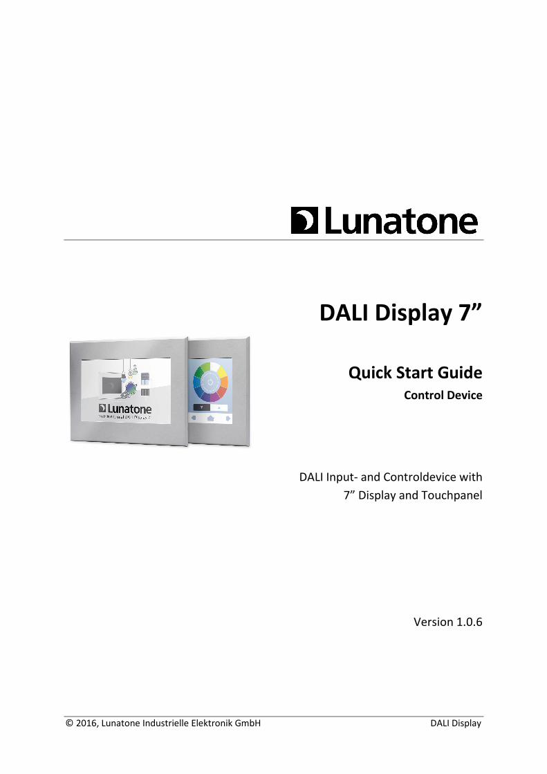
DALI Display 7”
Quick Start Guide
Control Device
DALI Input- and Controldevice with
7” Display and Touchpanel
Version 1.0.6
DALI Display, Manual V1.0.6 © 2016, Lunatone Industrielle Elektronik GmbH
DALI Display Control Device
Content
1. DALI Display – Features and Installation ......................................................................................... 3
1.1 Intended Use ....................................................................................................................... 3
1.2 Safety Instructions ............................................................................................................... 3
1.3 Features ............................................................................................................................... 3
1.4 Specification ........................................................................................................................ 4
1.5 Installation ........................................................................................................................... 5
2. Elementary Operating Functions ..................................................................................................... 6
3. Extended Operating Functions ........................................................................................................ 9
4. Configuration and Settings ............................................................................................................ 10
4.1 Design ................................................................................................................................ 12
4.2 Screensaver and Pincode Protection ................................................................................. 13
4.3 Date and Time ................................................................................................................... 14
4.4 Menu Bar ........................................................................................................................... 14
4.5 Site Numbering .................................................................................................................. 14
5. Commissioning .............................................................................................................................. 15
5.1 Adressing/Grouping ........................................................................................................... 15
5.2 Scenes and Color Scenes ................................................................................................... 18
5.3 Sequence (SQ), day-schedules (SDL), week-schedules (SDLL) ........................................... 23
5.4 Human Centric Lighting – Circadian daylight progression ................................................ 26
6. Ethernet – Remote Control ........................................................................................................... 27
7. System Update .............................................................................................................................. 31
8. Custom design ............................................................................................................................... 32
8.1 Photo of room with integrated luminary control .............................................................. 32
8.2 Room overview of a floor with controllable luminaries .................................................... 32
9. Additional Information and Equipment ........................................................................................ 34
10. Disclaimer .................................................................................................................................. 34
11. Glossary ..................................................................................................................................... 34
DALI Display, Manual V1.0.6 © 2016, Lunatone Industrielle Elektronik GmbH
1. DALI Display – Features and Installation
1.1 Intended Use
The DALI Display can be used for commissioning and control of DALI lighting systems. DALI is a
standardized digital protocol for the control of electronic ballasts for lighting systems according to
standard IEC62386. Exclusively ballast with DALI interface may be connected to one of the DALI-lines.
1.2 Safety Instructions
When operating the DALI display the following precautions must be considered:
Each user must carefully read and follow the instructions given in the manual.
The operator must ensure that the wiring instructions and specifications for DALI lines are
considered, the installation of the display must be performed by an qualified technician, who can
perform the required tasks and recognize potential danger due to professional training, knowledge
and experience, in particular the knowledge of pertinent regulations and standards.
Touching the screen with sharp objects can result in damage of the display.
1.3 Features
The DALI Display has connectors for two DALI lines (DALI A, DALI B). This allows installing up to 128
DALI ballasts.
Light control commands are based on DALI Scenes and Groups and are sent to both DALI lines
simultaneously. Scene commands are sent broadcast, group commands only to an individual DALI
group.
There are 16 Scenes and 16 Groups available for both DALI busses:
Number of DALI short addresses: 128
Number of DALI Groups: 16
Number of DALI Scenes: 16
Multi-Master Capability: Multiple control devices can be used on the DALI-lines.
DALI Display, Manual V1.0.6 © 2016, Lunatone Industrielle Elektronik GmbH
DALI Commands received on DALI line A are mirrored to DALI line B, this means that control devices
connected to DALI A can also control ballasts on DALI B.
Commands received on DALI B are not mirrored to DALI A, this allows to install controllers that only
affect one of the two DALI busses.
The DALI Display is a commissioning, control and input device for DALI controlled electronic ballasts.
Beside scene and group commands, algorithms for commissioning (addressing, grouping and scene
configuration) and automatic running processes (sequences, schedules and schedule lists) are
provided. Special methods like human centric lighting (circadian daylight trend) and colour control of
RGB-Dimmers is supported with the help of DALI Device Type 8 (DT8) standard.
By naming groups, scenes and automatic processes, custom backgrounds and screen saver image,
the device can be individually adapted to the application. Furthermore custom designed layouts are
offered as a manufacturer service.
The display can be controlled via the 7” touch control panel, but also via remote access through
Ethernet and hence can be operated via browser.
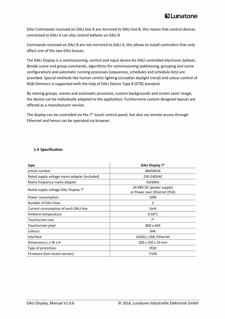
1.4 Specification
type DALI Display 7”
article number 86458626
Rated supply voltage mains adapter (included) 230-240VAC
Mains frequency mains adapter 50/60Hz
Rated supply voltage DALI Display 7” 24-48V DC (power supply)
or Power over Ethernet (PoE)
Power consumption 10W
Number of DALI lines 2
Current consumption of each DALI-line 2mA
Ambient temperature 0-50°C
Touchscreen size 7”
Touchscreen pixel 800 x 640
Colours 64k
Interface 2xDALI, USB, Ethernet
Dimensions L x W x H 200 x 150 x 20 mm
Type of protection IP20
Firmware (last recent version) V104
DALI Display, Manual V1.0.6 © 2016, Lunatone Industrielle Elektronik GmbH
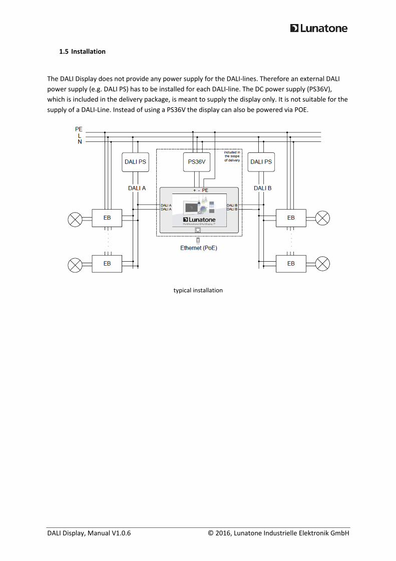
1.5 Installation
The DALI Display does not provide any power supply for the DALI-lines. Therefore an external DALI
power supply (e.g. DALI PS) has to be installed for each DALI-line. The DC power supply (PS36V),
which is included in the delivery package, is meant to supply the display only. It is not suitable for the
supply of a DALI-Line. Instead of using a PS36V the display can also be powered via POE.
typical installation
DALI Display, Manual V1.0.6 © 2016, Lunatone Industrielle Elektronik GmbH
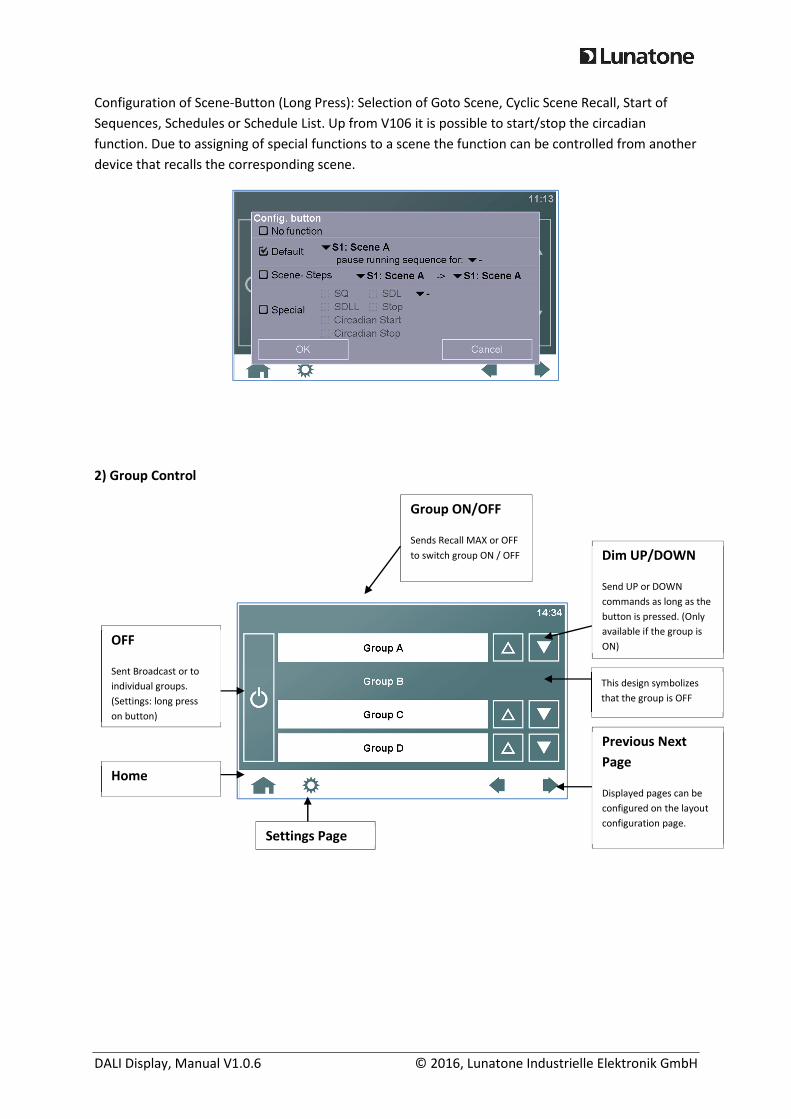
2. Elementary Operating Functions
The control of groups and scenes, using the buttons of predefined pages, is summarized under the
term of “elementary operating functions”. There are sites available for recalling scenes as well as for
switching and dimming of groups (unused pages can be disabled in the settings).
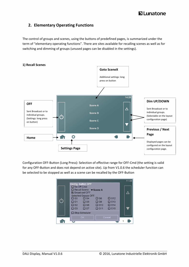
1) Recall Scenes
Configuration OFF-Button (Long Press): Selection of effective range for OFF-Cmd (the setting is valid
for any OFF-Button and does not depend on active site). Up from V1.0.6 the scheduler function can
be selected to be stopped as well as a scene can be recalled by the OFF-Button
Dim UP/DOWN
Sent Broadcast or to
individual groups.
(Selectable on the layout
configuration page)
Previous / Next
Page
Displayed pages can be
configured on the layout
configuration page.
Goto SceneX
Additional settings: long
press on button
OFF
Sent Broadcast or to
individual groups.
(Settings: long press
on button)
Settings Page
Home
DALI Display, Manual V1.0.6 © 2016, Lunatone Industrielle Elektronik GmbH
Configuration of Scene-Button (Long Press): Selection of Goto Scene, Cyclic Scene Recall, Start of
Sequences, Schedules or Schedule List. Up from V106 it is possible to start/stop the circadian
function. Due to assigning of special functions to a scene the function can be controlled from another
device that recalls the corresponding scene.
2) Group Control
Dim UP/DOWN
Send UP or DOWN
commands as long as the
button is pressed. (Only
available if the group is
ON)
Group ON/OFF
Sends Recall MAX or OFF
to switch group ON / OFF
Previous Next
Page
Displayed pages can be
configured on the layout
configuration page.
OFF
Sent Broadcast or to
individual groups.
(Settings: long press
on button)
Home
This design symbolizes
that the group is OFF
Settings Page
DALI Display, Manual V1.0.6 © 2016, Lunatone Industrielle Elektronik GmbH
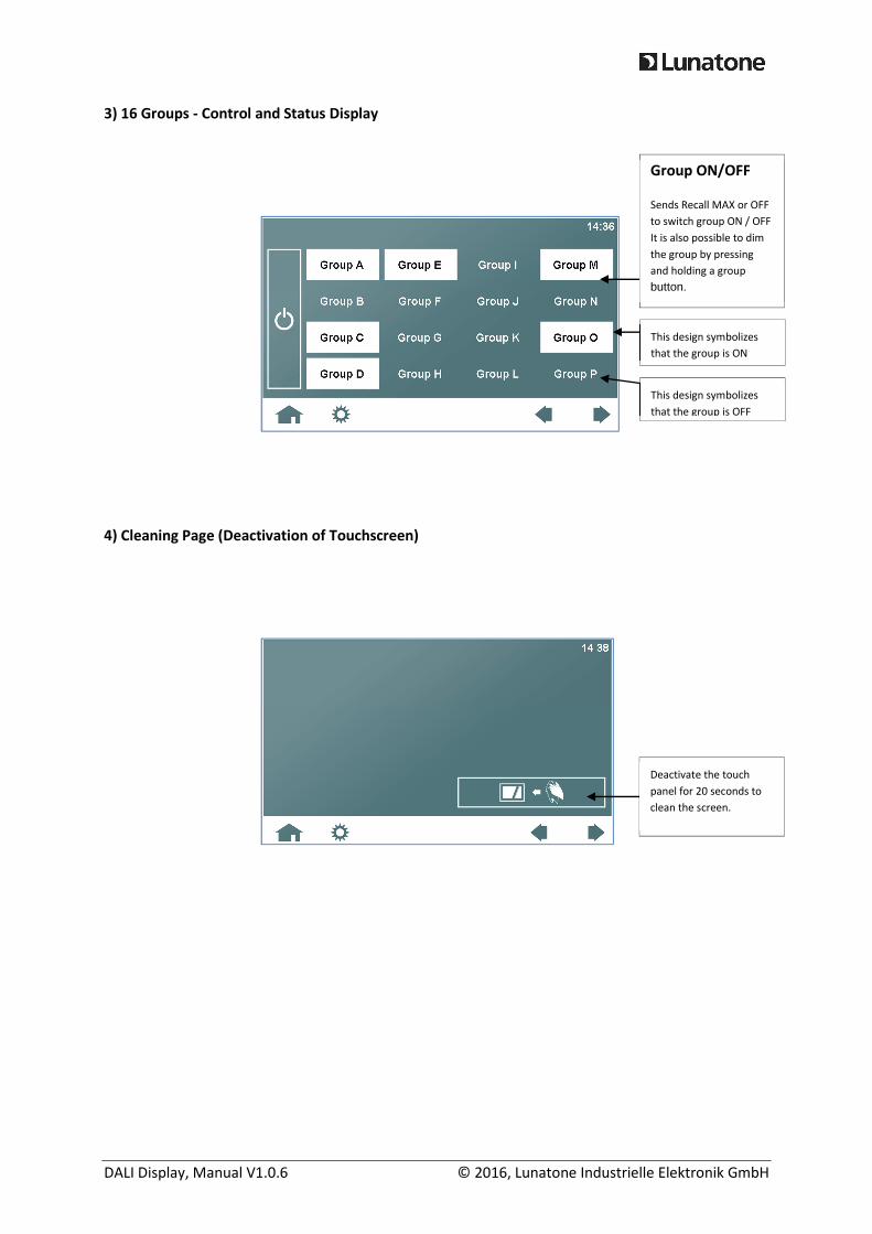
3) 16 Groups - Control and Status Display
4) Cleaning Page (Deactivation of Touchscreen)
Group ON/OFF
Sends Recall MAX or OFF
to switch group ON / OFF
It is also possible to dim
the group by pressing
and holding a group button.
This design symbolizes
that the group is ON
This design symbolizes
that the group is OFF
Deactivate the touch
panel for 20 seconds to
clean the screen.

DALI Display, Manual V1.0.6 © 2016, Lunatone Industrielle Elektronik GmbH
3. Extended Operating Functions
Extended operating functions offer additional control methods, which require either a set-up
procedure before usage or a control gear with specific DALI device type (DT8).
1) Automatic Processes (sequences, schedules, schedule lists)
2) Color Control for RGB-devices (DT8-Type: RGBWAF)
On this site a color can be selected and is immediately sent to the selected operating range.
Selection of
sequence,
schedule or
schedule list
Hold the button to open
the pop-up window to
load other processes
Dim UP/DOWN
Sent Broadcast or to
individual groups.
(Selectable on the layout
configuration page)
operating range
Short press: ON/OFF operating
range
Selection of operating range
Each group with DT8 (RGB) control gears
or Broadcast can be selected.
Color selection
color information is sent
to operating range
immediately after tipping
on the color
Start/Stop/Pause
control of the selected
process
indicator for running process
This symbol is shown on each site, when
process is active
RGBWAF - Details
Enter PopUp for detailed
settings
DALI Display, Manual V1.0.6 © 2016, Lunatone Industrielle Elektronik GmbH
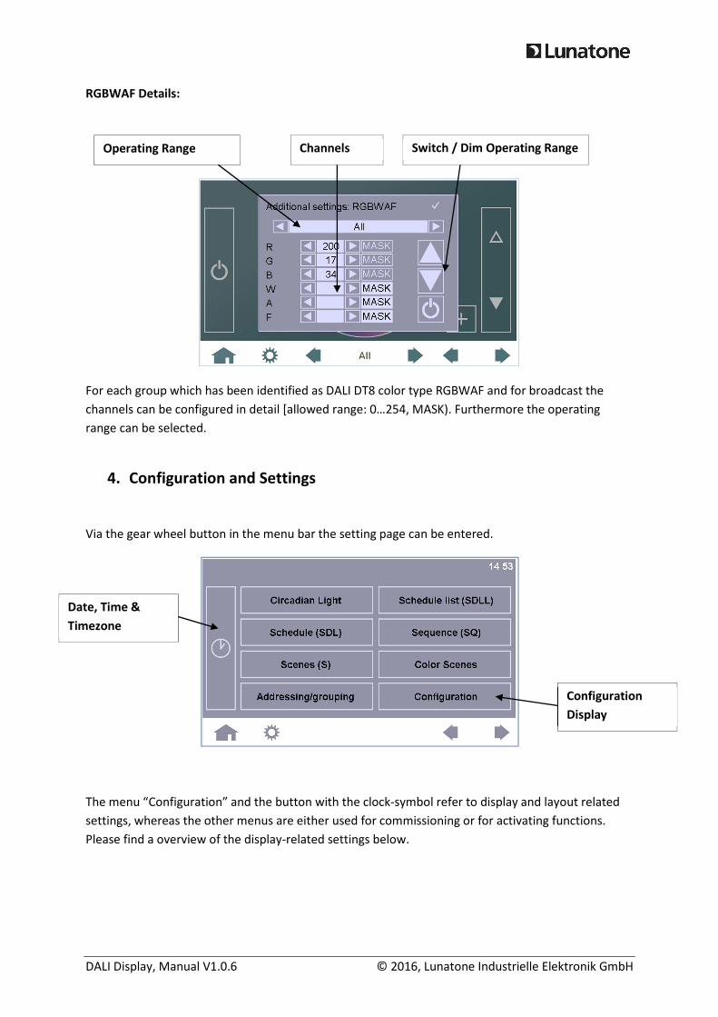
RGBWAF Details:
For each group which has been identified as DALI DT8 color type RGBWAF and for broadcast the
channels can be configured in detail [allowed range: 0…254, MASK). Furthermore the operating
range can be selected.
4. Configuration and Settings
Via the gear wheel button in the menu bar the setting page can be entered.
The menu “Configuration” and the button with the clock-symbol refer to display and layout related
settings, whereas the other menus are either used for commissioning or for activating functions.
Please find a overview of the display-related settings below.
Date, Time &
Timezone
Configuration
Display
Operating Range Channels Switch / Dim Operating Range
DALI Display, Manual V1.0.6 © 2016, Lunatone Industrielle Elektronik GmbH
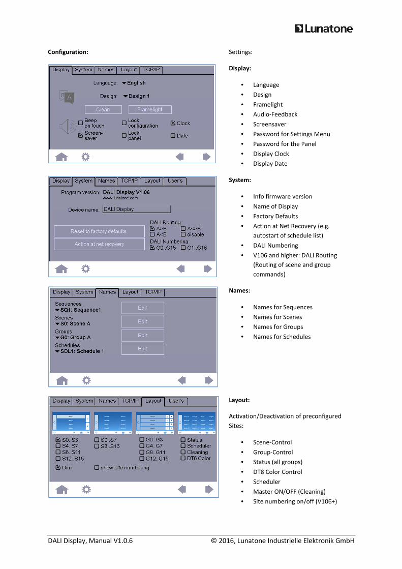
Configuration: Settings:
Display:
• Language
• Design
• Framelight
• Audio-Feedback
• Screensaver
• Password for Settings Menu
• Password for the Panel
• Display Clock
• Display Date
System:
• Info firmware version
• Name of Display
• Factory Defaults
• Action at Net Recovery (e.g.
autostart of schedule list)
• DALI Numbering
• V106 and higher: DALI Routing
(Routing of scene and group
commands)
Names:
• Names for Sequences
• Names for Scenes
• Names for Groups
• Names for Schedules
Layout:
Activation/Deactivation of preconfigured
Sites:
• Scene-Control
• Group-Control
• Status (all groups)
• DT8 Color Control
• Scheduler
• Master ON/OFF (Cleaning)
• Site numbering on/off (V106+)
DALI Display, Manual V1.0.6 © 2016, Lunatone Industrielle Elektronik GmbH
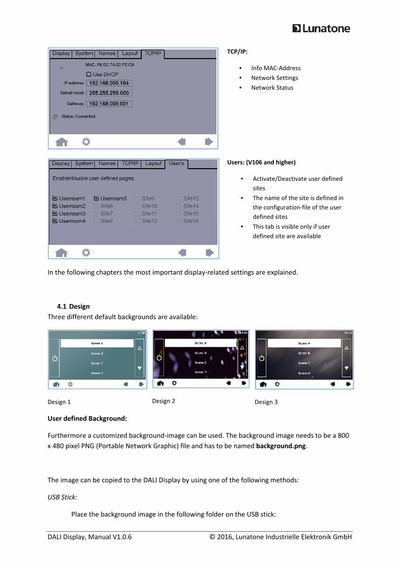
TCP/IP:
• Info MAC-Address
• Network Settings
• Network Status
Users: (V106 and higher)
• Activate/Deactivate user defined
sites
• The name of the site is defined in
the configuration-file of the user
defined sites
• This tab is visible only if user
defined site are available
In the following chapters the most important display-related settings are explained.
4.1 Design
Three different default backgrounds are available:
Design 1
Design 2
Design 3
User defined Background:
Furthermore a customized background-image can be used. The background image needs to be a 800
x 480 pixel PNG (Portable Network Graphic) file and has to be named background.png.
The image can be copied to the DALI Display by using one of the following methods:
USB Stick:
Place the background image in the following folder on the USB stick:
DALI Display, Manual V1.0.6 © 2016, Lunatone Industrielle Elektronik GmbH
/AutoRun/LTUpdate/home/resource/background.png
The file system on the DALI Display is case sensitive, so check for correct spelling. Then plug
in the USB stick; the file will be copied to the DALI Display.
Ethernet Network:
Please find the details about the upload function in chapter 6: Ethernet – Remote Control.
4.2 Screensaver and Pincode Protection
You can choose if a screen saver image should be displayed after an idle time of about 2 minutes.
Furthermore it is possible to add a pincode protection to the screen saver, and/or the configuration
page.
Default Pin for Lock Configuration: “1234”
Default Pin for Lock Panel: “5678”
The Master Pin “1220” does always unlock the panel.
The screen saver image needs to be a 800 x 480 pixel PNG (Portable Network Graphic) file and has to
be named screensaver.png.
The image can be copied to the DALI Display by using one of the following methods:
USB Stick:
Place the background image in the following folder on the USB stick:
beeper ON/OFF
display screen saver
image after 2 minutes of
inactivity
pin code protection for
configuration page
pin code protection after
screensaver has been
activated
DALI Display, Manual V1.0.6 © 2016, Lunatone Industrielle Elektronik GmbH
/AutoRun/LTUpdate/home/resource/screensaver.png
The file system on the DALI Display is case sensitive, so please check for correct spelling. Then
plug in the USB stick; the file will be copied to the DALI Display.
Ethernet Network:
Please find the details about the upload function in chapter 6: Ethernet – Remote Control.
4.3 Date and Time
If date and clock are activated in the display-tab, the time and date is shown in the upper right corner
on the control pages. The page for setting date, time and timezone can be entered by selection of
the button with the clock-symbol on the setting-page.
4.4 Menu Bar
Up from V106 the menu bar can be activated/deactivated by pressing 5 seconds on the left top of a
controls-site (embedded and user-defined). If a PIN for settings is enabled, the function is pin-
protected.
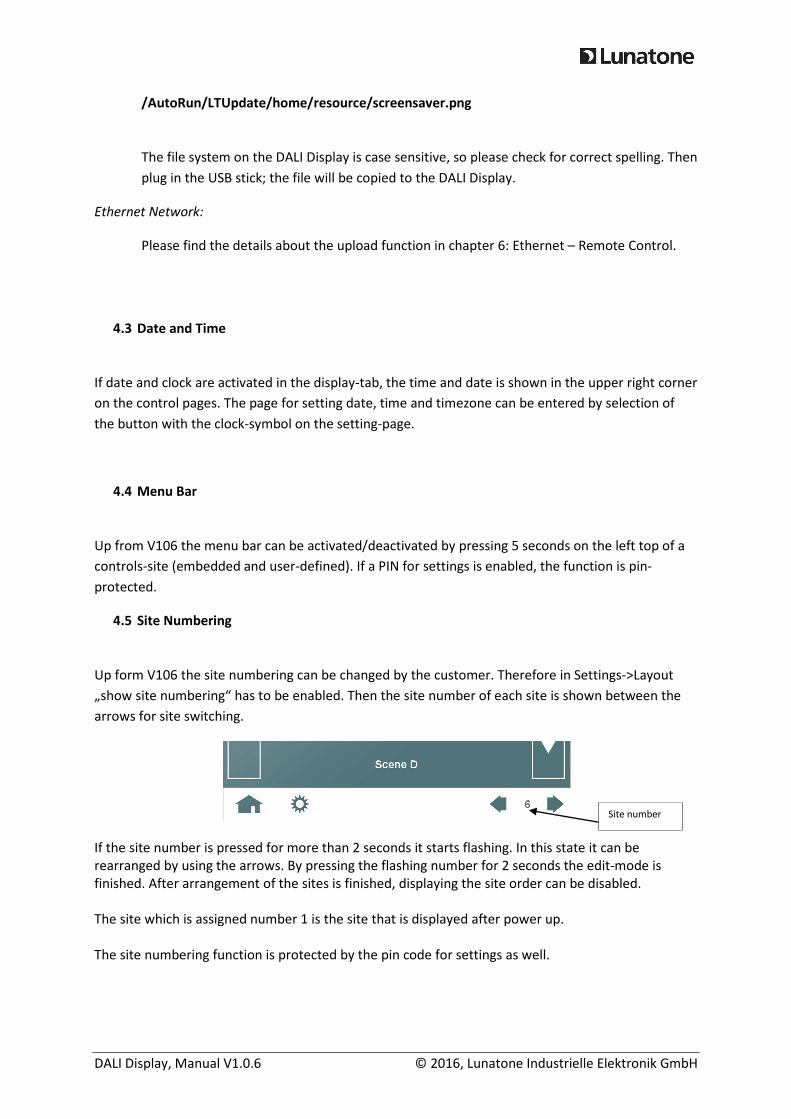
4.5 Site Numbering
Up form V106 the site numbering can be changed by the customer. Therefore in Settings->Layout
„show site numbering“ has to be enabled. Then the site number of each site is shown between the
arrows for site switching.
If the site number is pressed for more than 2 seconds it starts flashing. In this state it can be
rearranged by using the arrows. By pressing the flashing number for 2 seconds the edit-mode is
finished. After arrangement of the sites is finished, displaying the site order can be disabled.
The site which is assigned number 1 is the site that is displayed after power up.
The site numbering function is protected by the pin code for settings as well.
Site number
DALI Display, Manual V1.0.6 © 2016, Lunatone Industrielle Elektronik GmbH
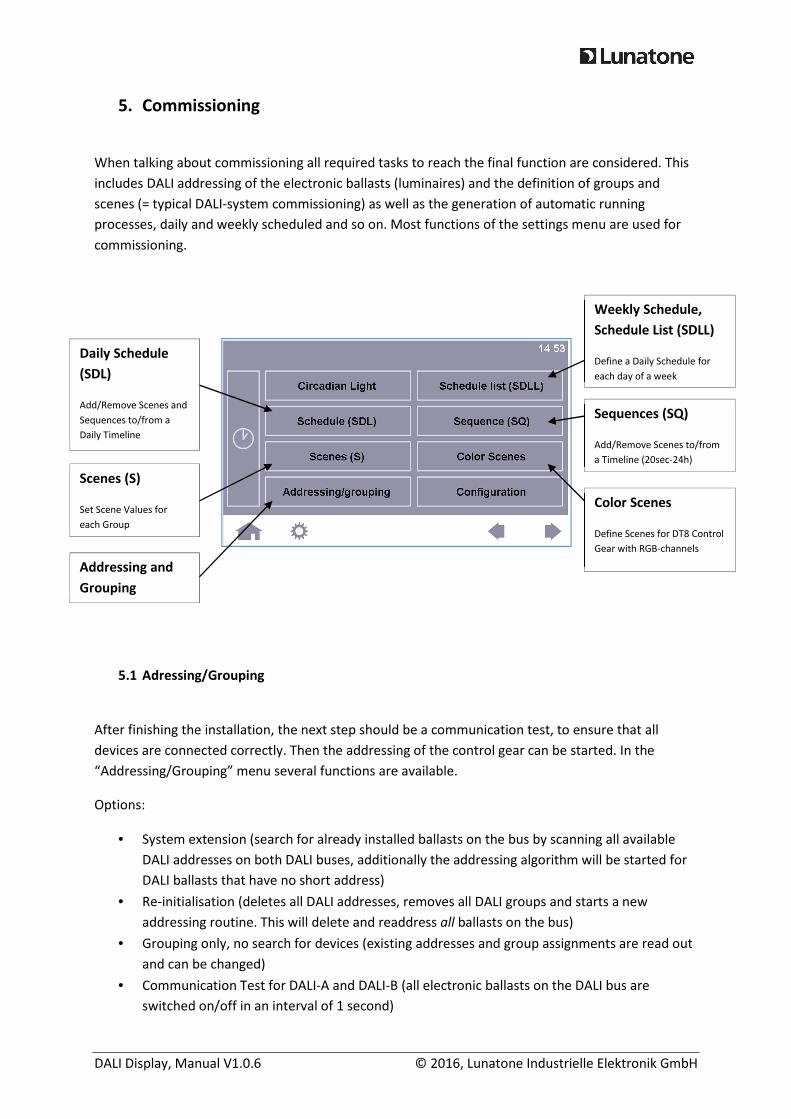
5. Commissioning
When talking about commissioning all required tasks to reach the final function are considered. This
includes DALI addressing of the electronic ballasts (luminaires) and the definition of groups and
scenes (= typical DALI-system commissioning) as well as the generation of automatic running
processes, daily and weekly scheduled and so on. Most functions of the settings menu are used for
commissioning.
5.1 Adressing/Grouping
After finishing the installation, the next step should be a communication test, to ensure that all
devices are connected correctly. Then the addressing of the control gear can be started. In the
“Addressing/Grouping” menu several functions are available.
Options:
• System extension (search for already installed ballasts on the bus by scanning all available
DALI addresses on both DALI buses, additionally the addressing algorithm will be started for
DALI ballasts that have no short address)
• Re-initialisation (deletes all DALI addresses, removes all DALI groups and starts a new
addressing routine. This will delete and readdress all ballasts on the bus)
• Grouping only, no search for devices (existing addresses and group assignments are read out
and can be changed)
• Communication Test for DALI-A and DALI-B (all electronic ballasts on the DALI bus are
switched on/off in an interval of 1 second)
Weekly Schedule,
Schedule List (SDLL)
Define a Daily Schedule for
each day of a week
Sequences (SQ)
Add/Remove Scenes to/from
a Timeline (20sec-24h)
Color Scenes
Define Scenes for DT8 Control
Gear with RGB-channels
Scenes (S)
Set Scene Values for
each Group
Daily Schedule
(SDL)
Add/Remove Scenes and
Sequences to/from a
Daily Timeline
Addressing and
Grouping

DALI Display, Manual V1.0.6 © 2016, Lunatone Industrielle Elektronik GmbH
The duration of the addressing procedure depends on the number of the connected DALI devices and
can last several minutes. After the addressing procedure has been finished the found ballasts can be
added to or removed from the 16 DALI groups.
Grouping:
Note: A control gear (ballast) can be assigned to several groups
Selecting a ballast: A ballast can be “optically selected” with the left/right arrows. The selected
ballast will give an optical feedback (switched to DALI MAX-Level)
SAVE Group
Save Group Settings to
Display and Control Gear
LOAD Group
Load and Edit another group
Active Group
Indicates which
group you are
editing
Selection of control gear
DALI Display, Manual V1.0.6 © 2016, Lunatone Industrielle Elektronik GmbH
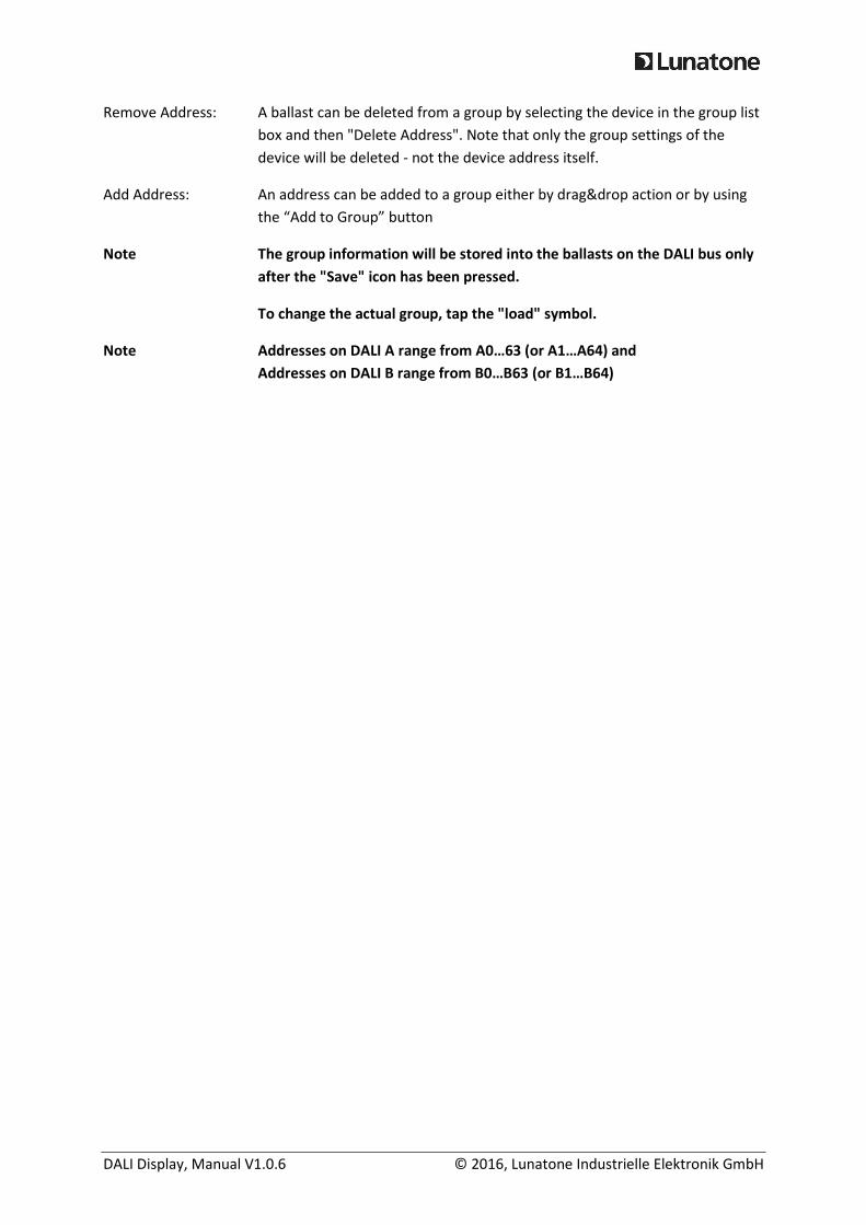
Remove Address: A ballast can be deleted from a group by selecting the device in the group list
box and then "Delete Address". Note that only the group settings of the
device will be deleted - not the device address itself.
Add Address: An address can be added to a group either by drag&drop action or by using
the “Add to Group” button
Note The group information will be stored into the ballasts on the DALI bus only
after the "Save" icon has been pressed.
To change the actual group, tap the "load" symbol.
Note Addresses on DALI A range from A0…63 (or A1…A64) and
Addresses on DALI B range from B0…B63 (or B1…B64)

DALI Display, Manual V1.0.6 © 2016, Lunatone Industrielle Elektronik GmbH
5.2 Scenes and Color Scenes
Scenes(S)
When pressing the „Scenes“-Button you enter the scene-oriented configuration menu, there
appropriate values can be assigned to the currently active scene of each group. Always 4 groups are
displayed on one page. Other groups can be selected using the arrow-keys in the menubar. Active
scene can be changed with “Load Scene” and settings can be stored using “Save Scene”.
The settings in the scene configuration menu are automatically sent to the ballasts. Hence an optical
feedback is given before storing a scene.
Settings: In each group, a brightness level between 0-100% can be assigned to the selected scene.
Additional options are: OFF (group off) or MASK (group shall not react and keep current settings
when the scene is called). Depending on the device type of the DALI control gear, further setting
options are available, such as color temperature or RGB-color value (DALI DT8 devices), (these
special properties can be edited by tapping the corresponding field). The color temperature can be
entered via a keypad, for editing the color of a scene you will be redirected to the “Color Scene”
configuration menu.
Hint: Only DT8-devices which identify themselves as color type Tc or RGBWAF are
supported.
Hint: In mixed groups (e.g. with Tc and RGBWAF or multitype devices) the scene color
type can be selected by clicking the group name.
Active Scene
Display of Scene Number and
assigned Name
More Groups
Switch to the
configuration site of the
next 4 groups (4 sites with
4 groups on each site)
Brightness in % /
MASK /OFF
parameters (available
for each group):
- direct arc
power (in %)
- MASK
- OFF
Special Scene-Settings (dependent on Device Type):
Scene values, which depend on the type of control gear, such as color or color temperature. The
special settings can be simply edited by tapping. Press group number for changing color type
ofmixed groups
Clear Color / Tc
Reset Color Scene values
(MASK)
DALI Display, Manual V1.0.6 © 2016, Lunatone Industrielle Elektronik GmbH
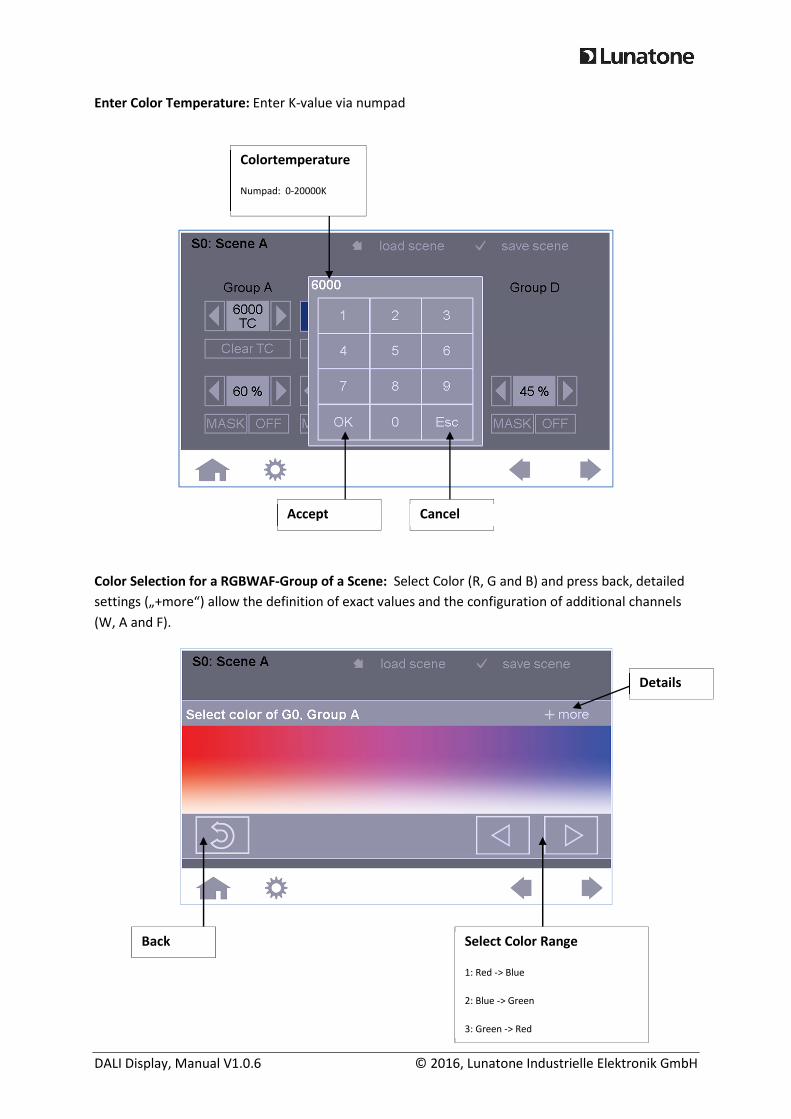
Enter Color Temperature: Enter K-value via numpad
Color Selection for a RGBWAF-Group of a Scene: Select Color (R, G and B) and press back, detailed
settings („+more“) allow the definition of exact values and the configuration of additional channels
(W, A and F).
Colortemperature
Numpad: 0-20000K
Select Color Range
1: Red -> Blue
2: Blue -> Green
3: Green -> Red
Back
Cancel Accept
Details
DALI Display, Manual V1.0.6 © 2016, Lunatone Industrielle Elektronik GmbH
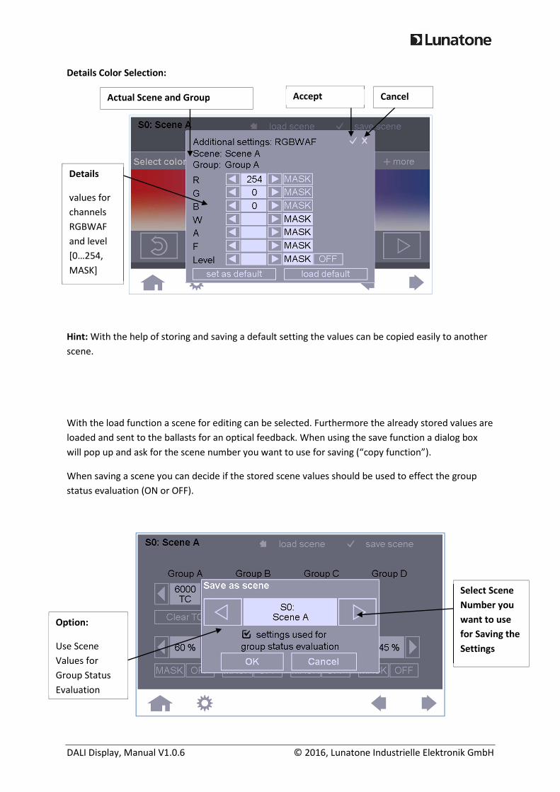
Details Color Selection:
Hint: With the help of storing and saving a default setting the values can be copied easily to another
scene.
With the load function a scene for editing can be selected. Furthermore the already stored values are
loaded and sent to the ballasts for an optical feedback. When using the save function a dialog box
will pop up and ask for the scene number you want to use for saving (“copy function”).
When saving a scene you can decide if the stored scene values should be used to effect the group
status evaluation (ON or OFF).
Select Scene
Number you
want to use
for Saving the
Settings
Option:
Use Scene
Values for
Group Status
Evaluation
Actual Scene and Group Cancel Accept
Details
values for
channels
RGBWAF
and level
[0…254,
MASK]
DALI Display, Manual V1.0.6 © 2016, Lunatone Industrielle Elektronik GmbH
After pressing “OK” you will be asked for an additional confirmation to store the scene values in the
ballasts.
NOTE: Take care that groups always have the same scene levels, if devices are
assigned to multiple groups. Otherwise the scene value with the highest
assigned group number is stored in the control gear
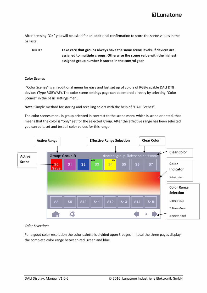
Color Scenes
“Color Scenes” is an additional menu for easy and fast set up of colors of RGB-capable DALI DT8
devices (Type RGBWAF). The color scene settings page can be entered directly by selecting “Color
Scenes” in the basic settings menu.
Note: Simple method for storing and recalling colors with the help of “DALI-Scenes”.
The color scenes menu is group oriented in contrast to the scene menu which is scene oriented, that
means that the color is “only” set for the selected group. After the effective range has been selected
you can edit, set and test all color values for this range.
Color Selection:
For a good color resolution the color palette is divided upon 3 pages. In total the three pages display
the complete color range between red, green and blue.
Color
Indicator
Select color
Effective Range Selection
Color Range
Selection
1: Red->Blue
2: Blue->Green
3: Green->Red
Clear Color Active Range
Active
Scene
Clear Color
DALI Display, Manual V1.0.6 © 2016, Lunatone Industrielle Elektronik GmbH
Setting and saving scene colors:
For color verification the selected color is being sent immediately to the luminary.
If a scene button (S0-15) is being pressed, the word “SAVE” starts to blink, the color can now be
selected. While it is blinking the color can be changed numerous times, the scene field will display
the current color selection. With the “+more”-option the scene can be configured in detail (Values
for R,G,B as well as for W,A & F and even level can be defined). If any of these additional settings are
defined this will be indicated by the term “WAF” or “xx%” in the field of the corresponding scene (see
S3 & S4).
When the word button with blinking “SAVE” is being pressed, the new settings will be saved. All
other actions (pressing any other key) result in cancelation of the scene configuration and the
original color setting is being restored.
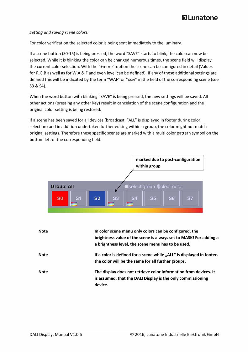
If a scene has been saved for all devices (broadcast, “ALL” is displayed in footer during color
selection) and in addition undertaken further editing within a group, the color might not match
original settings. Therefore these specific scenes are marked with a multi color pattern symbol on the
bottom left of the corresponding field.
Note In color scene menu only colors can be configured, the
brightness value of the scene is always set to MASK! For adding a
a brightness level, the scene menu has to be used.
Note If a color is defined for a scene while „ALL“ is displayed in footer,
the color will be the same for all further groups.
Note The display does not retrieve color information from devices. It
is assumed, that the DALI Display is the only commissioning
device.
marked due to post-configuration
within group
DALI Display, Manual V1.0.6 © 2016, Lunatone Industrielle Elektronik GmbH
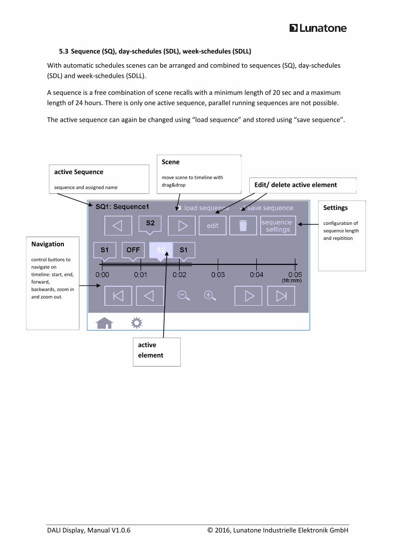
5.3 Sequence (SQ), day-schedules (SDL), week-schedules (SDLL)
With automatic schedules scenes can be arranged and combined to sequences (SQ), day-schedules
(SDL) and week-schedules (SDLL).
A sequence is a free combination of scene recalls with a minimum length of 20 sec and a maximum
length of 24 hours. There is only one active sequence, parallel running sequences are not possible.
The active sequence can again be changed using “load sequence” and stored using “save sequence”.
active Sequence
sequence and assigned name
Scene
move scene to timeline with
drag&drop
Settings
configuration of
sequence length
and repitition
Navigation
control buttons to
navigate on
timeline: start, end,
forward,
backwards, zoom in
and zoom out.
active
element
Edit/ delete active element
DALI Display, Manual V1.0.6 © 2016, Lunatone Industrielle Elektronik GmbH
After selecting a sequence for configuration (via the “load button” in footer) the duration of the
sequence can be set (button in footer on the right end). It is also possible to repeat the sequence,
between 1 and 6 repetitions can be set or the mode: endless.
The scenes can be selected with the arrow buttons, left and right of the rhombus shaped field. The
rhombus shaped field displays the currently available scene and can be moved to the timeline with
drag&drop. The scene can be removed by pressing the scene shortly and additionally pressing the
button “delete element”. By holding the scene rhombus on the timeline a pop-up will open for more
precise configuration. Here “S1” from previous example:
Day-Schedules, also referred to as Schedules (SDL), can be configured like sequences. One difference,
Day-Schedules are limited to 24 hours and their timing is related to the actual time of the day.
Sequences can be embedded in schedules, they are being selected like scenes, with the arrows left
and right of the rhombus.
Time
exact
configuration of
time within
sequence
duration
Scene
Scene, ought to be
retrieved
Fading
fade-time after
which the scene
value should be
reached
repeat the
sequence
Times of
repetition:
1 …6 , Loop
Duration
Duration of sequence,
precise time can be set
with arrows.
Timeframe: 20s to 24h
DALI Display, Manual V1.0.6 © 2016, Lunatone Industrielle Elektronik GmbH
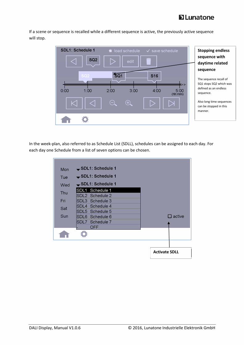
If a scene or sequence is recalled while a different sequence is active, the previously active sequence
will stop.
In the week-plan, also referred to as Schedule List (SDLL), schedules can be assigned to each day. For
each day one Schedule from a list of seven options can be chosen.
Stopping endless
sequence with
daytime related
sequence
The sequence recall of
SQ1 stops SQ2 which was
defined as an endless
sequence.
Also long time sequences
can be stopped in this
manner.
Activate SDLL
DALI Display, Manual V1.0.6 © 2016, Lunatone Industrielle Elektronik GmbH
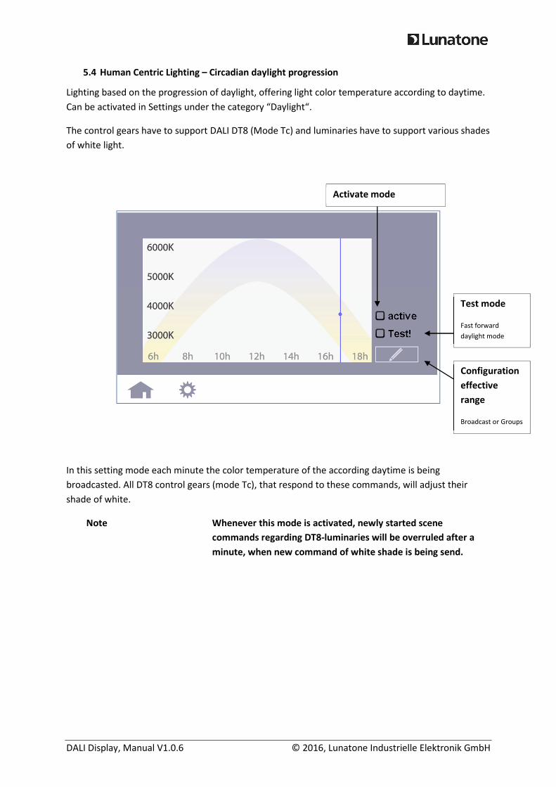
5.4 Human Centric Lighting – Circadian daylight progression
Lighting based on the progression of daylight, offering light color temperature according to daytime.
Can be activated in Settings under the category “Daylight“.
The control gears have to support DALI DT8 (Mode Tc) and luminaries have to support various shades
of white light.
In this setting mode each minute the color temperature of the according daytime is being
broadcasted. All DT8 control gears (mode Tc), that respond to these commands, will adjust their
shade of white.
Note Whenever this mode is activated, newly started scene
commands regarding DT8-luminaries will be overruled after a
minute, when new command of white shade is being send.
Activate mode
Test mode
Fast forward
daylight mode
Configuration
effective
range
Broadcast or Groups
DALI Display, Manual V1.0.6 © 2016, Lunatone Industrielle Elektronik GmbH
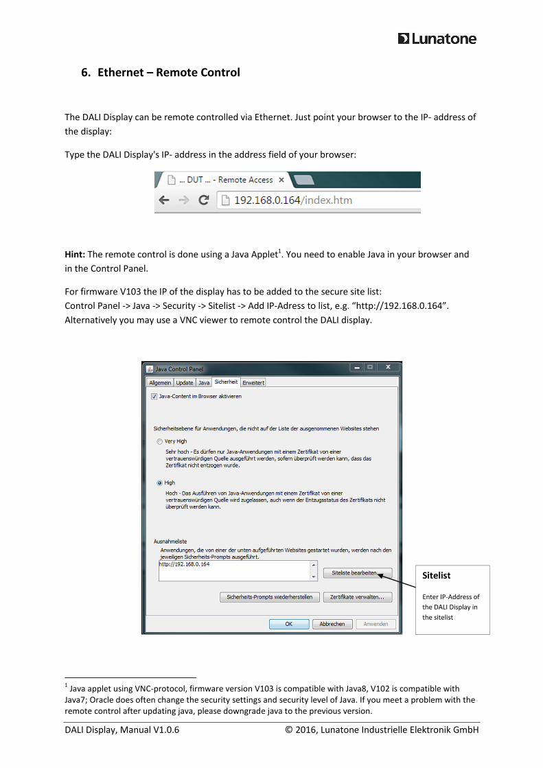
6. Ethernet – Remote Control
The DALI Display can be remote controlled via Ethernet. Just point your browser to the IP- address of
the display:
Type the DALI Display's IP- address in the address field of your browser:
Hint: The remote control is done using a Java Applet1. You need to enable Java in your browser and
in the Control Panel.
For firmware V103 the IP of the display has to be added to the secure site list:
Control Panel -> Java -> Security -> Sitelist -> Add IP-Adress to list, e.g. “http://192.168.0.164”.
Alternatively you may use a VNC viewer to remote control the DALI display.
1 Java applet using VNC-protocol, firmware version V103 is compatible with Java8, V102 is compatible with
Java7; Oracle does often change the security settings and security level of Java. If you meet a problem with the
remote control after updating java, please downgrade java to the previous version.
Sitelist
Enter IP-Address of
the DALI Display in
the sitelist
DALI Display, Manual V1.0.6 © 2016, Lunatone Industrielle Elektronik GmbH
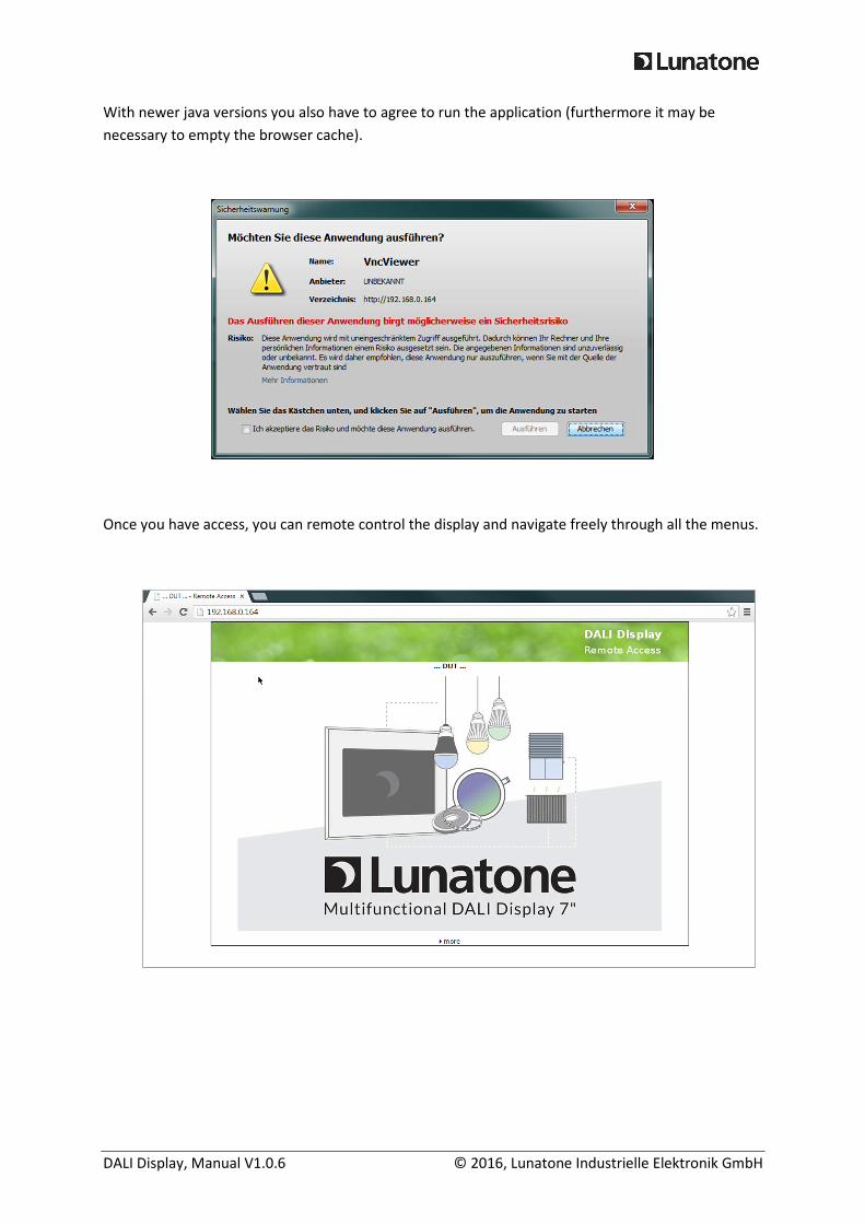
With newer java versions you also have to agree to run the application (furthermore it may be
necessary to empty the browser cache).
Once you have access, you can remote control the display and navigate freely through all the menus.
DALI Display, Manual V1.0.6 © 2016, Lunatone Industrielle Elektronik GmbH
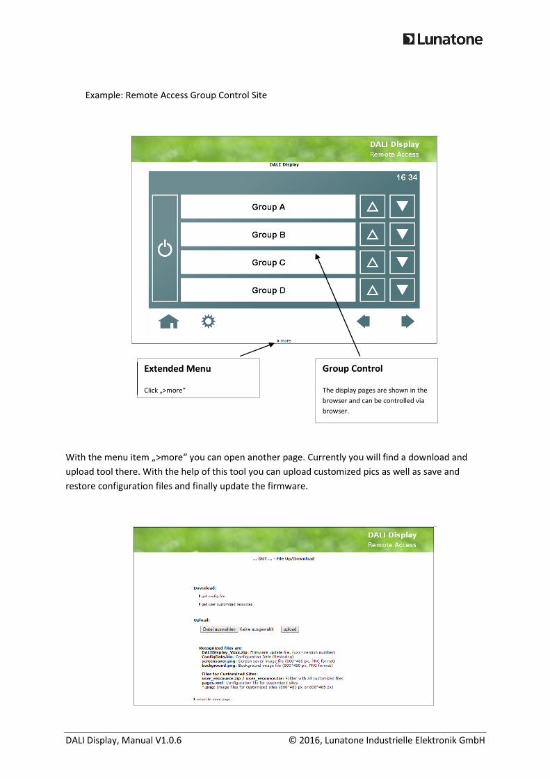
Example: Remote Access Group Control Site
With the menu item „>more“ you can open another page. Currently you will find a download and
upload tool there. With the help of this tool you can upload customized pics as well as save and
restore configuration files and finally update the firmware.
Group Control
The display pages are shown in the
browser and can be controlled via
browser.
Extended Menu
Click „>more“
DALI Display, Manual V1.0.6 © 2016, Lunatone Industrielle Elektronik GmbH
Supported files are:
- DALIDisplay_Vxxx.zip firmware DALI Display (xxx= version number)
- ConfigData.bin DALI Display configuration file (restore a previous
downloaded configuration)
- screensaver.png customized screensaver (800*480)
- background.png customized background (800*480)
Furthermore user defined images and configuration files for customized pages can be uploaded.
Contact the manufacturer for further details.
As alternative to the browser you can use a VNC-Viewer to remote access the DALI-Display (Note: the
download/upload site can be accessed only via browser).

DALI Display, Manual V1.0.6 © 2016, Lunatone Industrielle Elektronik GmbH
7. System Update
For firmware updates a zip file DALIDisplay_Vxxx.zip is provided. xxx is a placeholder for the version
number of the update.
There are two possibilities to update the Display:
USB Stick: Unzip the file DALIDisplay_Vxxx.zip into the root directory of an USB stick.
Then plug in the USB stick into the DALI Display and follow the instructions on
the screen.
Ethernet: Just upload the file DALIDisplay_Vxxx.zip on the upload page of the DALI
Display web page (details see chapter 6).
DALI Display, Manual V1.0.6 © 2016, Lunatone Industrielle Elektronik GmbH
8. Custom design
From Firmware V103 onwards, custom pages can be uploaded to the DALI Display. Individual Designs
can be developed for multiple scenarios. Lunatone offers this service upon request.
Two examples of custom designs are shown below:
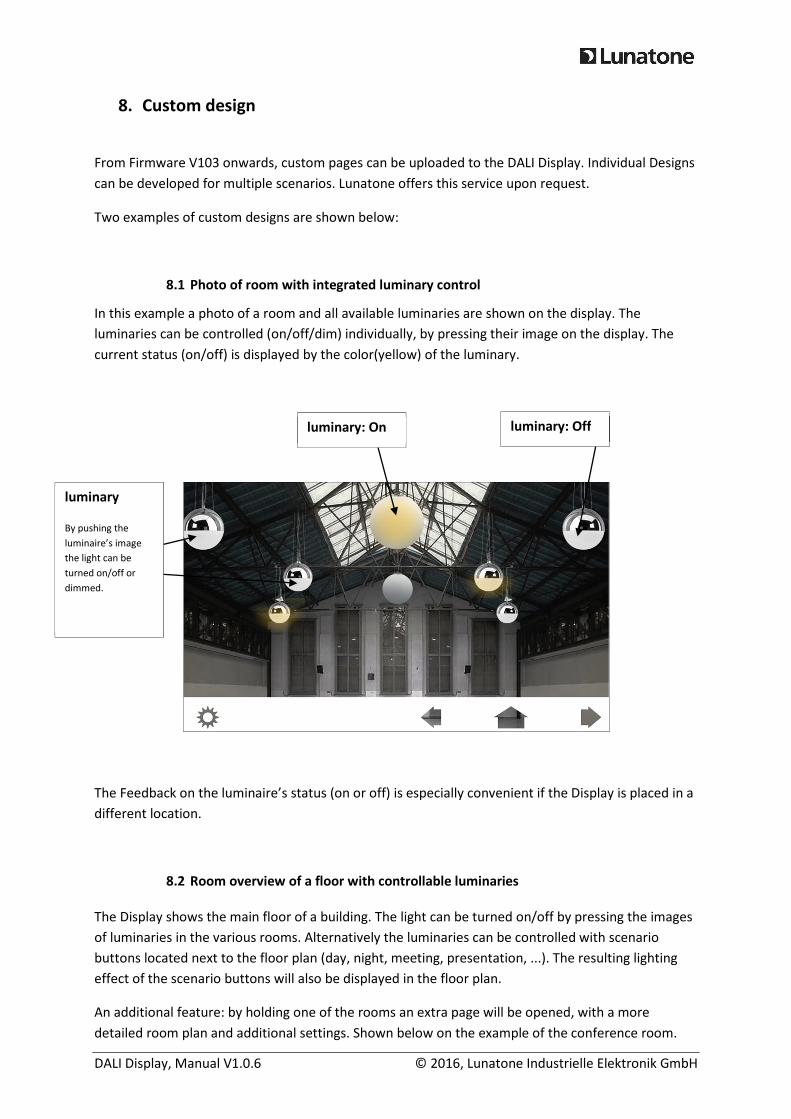
8.1 Photo of room with integrated luminary control
In this example a photo of a room and all available luminaries are shown on the display. The
luminaries can be controlled (on/off/dim) individually, by pressing their image on the display. The
current status (on/off) is displayed by the color(yellow) of the luminary.
The Feedback on the luminaire’s status (on or off) is especially convenient if the Display is placed in a
different location.
8.2 Room overview of a floor with controllable luminaries
The Display shows the main floor of a building. The light can be turned on/off by pressing the images
of luminaries in the various rooms. Alternatively the luminaries can be controlled with scenario
buttons located next to the floor plan (day, night, meeting, presentation, ...). The resulting lighting
effect of the scenario buttons will also be displayed in the floor plan.
An additional feature: by holding one of the rooms an extra page will be opened, with a more
detailed room plan and additional settings. Shown below on the example of the conference room.
luminary
By pushing the
luminaire’s image
the light can be
turned on/off or
dimmed.
luminary: On luminary: Off
DALI Display, Manual V1.0.6 © 2016, Lunatone Industrielle Elektronik GmbH
Conference room, detailed overview:
scenes
recall of
several scenes
OFF
general- off
rooms
visualization of
lighting status
and direct
control of
luminaries
conference room
short click: Light on/off
hold button: enter detailed
room overview
back
return to main
floor plan
scenes
scenes regarding
the conference
room
-Aus
OFF
light off in
conference
room dimming
light brighter, darker
luminaries
optional:
direct control
of luminaries
DALI Display, Manual V1.0.6 © 2016, Lunatone Industrielle Elektronik GmbH
9. Additional Information and Equipment
DALI Display datasheet
http://lunatone.at/en/downloads/Lunatone_Art86458626_DALI_Display_Datasheet_EN.pdf
DALI-Manual English http://www.dali- ag.org/c/manual_gb.pdf
DALI PS – power supply for a DALI line
http://lunatone.at/en/downloads/Lunatone_ Art24033444_DALI_PS_Datasheet_EN.pdf
Technical Support: [email protected]
Requests: [email protected]
www.lunatone.com
10. Disclaimer
Subject to change. Information provided without guarantee. The datasheet refers to the current
state delivery.
The function in installations with other devices must be tested for compatibility in advance.
11. Glossary
term description
control gear Electronic ballast for lighting purposes
Broadcast According to DALI: Effective range = all operating units
Color Scene
Using a DALI scene for storing color information only without brightness level
(level=”MASK”)
DALI Digital Addressable Lighting Interface, standard for lighting control (IEC 62386).
Device Type 8
DALI standard for colour control (short DT8), all device requirements regarding colour
control via DALI are combined in the norm IEC 62386-209.
individual device
address
Each DALI-device is equipped with an individual address, with this address the device
can be identified and addressed.
group a combination of several control gear
group address
According to DALI: Control gear added to a group can be controlled simultaneous via the
group address.
MASK
Special DALI value (0xFF). If this value is send as brightness value, than the control gear
will not change its current brightness value. If this value is saved as a scene value, the
recall of this scene will not effect the current lighting status. Currently active fades will
be stopped if MASK is received.
Schedule (SDL) Daytime related schedule, starts at 00:00 and ends at 24:00, can be started, paused and
DALI Display, Manual V1.0.6 © 2016, Lunatone Industrielle Elektronik GmbH
stopped any time.
Schedule List (SDLL) Week schedule with a 7 day plan. For each day a time related schedule can be set.
Sequence (SQ) Time related process, can be started, paused and stopped any time.
Scene (S) Lighting scenario