Embed Size (px)
Citation preview
DAIMSCALE
Final Design Report
Devin Bodmer [email protected] Chris Marrale [email protected]
Jase Sasaki [email protected]
Sponsors
Daimler Trucks North America: David Smith, Nikola Noxon, Thomas Stevens
Dr. Charles Birdsong, Cal Poly Mechanical Engineering Professor
Mechanical Engineering Department
California Polytechnic State University San Luis Obispo
2018
2
Statement of Disclaimer Since this project is a result of a class assignment, it has been graded and accepted as fulfillment of the
course requirements. Acceptance does not imply technical accuracy or reliability. Any use of information
in this report is done at the risk of the user. These risks may include catastrophic failure of the device or
infringement of patent or copyright laws. California Polytechnic State University at San Luis Obispo and
its staff cannot be held liable for any use or misuse of the project.
3
Table of Contents
Table of Figures .............................................................................................................................. 6
Table of Tables ............................................................................................................................... 8
1. Introduction ................................................................................................................................. 9
2. Background ................................................................................................................................. 9
2.1 - Customer Needs .................................................................................................................. 9
2.2 - Existing Products .............................................................................................................. 10
2.3 - Relevant Technical Papers................................................................................................ 11
3. Objectives ................................................................................................................................. 13
3.1 - Problem Statement ............................................................................................................ 13
3.2 - Boundary Diagram ........................................................................................................... 13
3.3 - Sponsor Needs & Wants ................................................................................................... 14
3.4 - QFD Process ..................................................................................................................... 14
3.5 - Specifications Table ......................................................................................................... 15
3.5.1 - Similitude of Acceleration ......................................................................................... 16
3.5.2 - Similitude of Deceleration ......................................................................................... 16
3.5.3 - Similitude of Top Speed ............................................................................................ 16
3.5.4 - Similitude of Suspension ........................................................................................... 16
3.5.5 - Similitude of Steering ................................................................................................ 16
3.5.6 - Similitude of Wheel Base / Track Width................................................................... 17
3.5.7 - Adjustable 5th Wheel ................................................................................................ 17
3.5.8 - Adjustable Trailer Axles ............................................................................................ 17
3.5.9 - Wireless Manual Control with Upgradability ........................................................... 17
3.5.10 - Space for Sensor Hardware in Tractor .................................................................... 17
3.5.11 - Vehicle Weight / CG location ................................................................................. 17
3.5.12 – Cost ............................................................................................................................. 18
3.5.13 - Vehicle Can Withstand Collisions ........................................................................... 18
3.5.14 - Tractor Design ......................................................................................................... 18
3.5.15 - Trailer Design .......................................................................................................... 18
3.5.16 - Portability ................................................................................................................ 18
3.5.17 - Scale......................................................................................................................... 18
4. Conceptual Design Development ............................................................................................. 19
4.1 - Vehicle Dynamics............................................................................................................. 19
4.2 - Similitude.......................................................................................................................... 22
4
4.3 - Scale.................................................................................................................................. 23
4.4 - Functional Decomposition ................................................................................................ 24
4.5 - Tractor Chassis ................................................................................................................. 24
4.6 - Tractor Steering ................................................................................................................ 25
4.7 - Suspension ........................................................................................................................ 27
4.8 - Drivetrain .......................................................................................................................... 28
4.9 - Adjustable 5th Wheel ........................................................................................................ 29
4.10 Trailer Chassis .................................................................................................................. 31
4.11 - Adjustable Trailer Axles ................................................................................................. 32
4.12 Modular Box/Flat-Bed Trailer .......................................................................................... 33
4.12 - Mechanical Brake ........................................................................................................... 34
4.13 - Tires ................................................................................................................................ 35
4.14 - Hazard Checklist............................................................................................................. 37
5. Final Design .............................................................................................................................. 38
5.1 Tractor Design .................................................................................................................... 38
5.2 Fifth Wheel Design ............................................................................................................. 39
5.3 Trailer Design ..................................................................................................................... 40
5.4 Shocks ................................................................................................................................. 41
5.5 Electronics........................................................................................................................... 43
5.7 Data Logging Hardware ...................................................................................................... 46
5.8 CAD Images of Final Design .............................................................................................. 47
5.8 Weight Analysis .................................................................................................................. 48
5.9 Cost Analysis ...................................................................................................................... 48
5.10 Cost Reduction .................................................................................................................. 50
6. Manufacturing ........................................................................................................................... 51
6.1 Procurement / Purchase List ............................................................................................... 51
6.2 Rapid Prototyping ............................................................................................................... 51
6.2.1 Tractor Suspension Plate.............................................................................................. 51
6.2.2 Trailer Suspension Plate .............................................................................................. 52
6.2.3 Tractor Front Suspension Mount ................................................................................. 52
6.2.4 Servo Bracket ............................................................................................................... 52
6.2.5 Tractor and Trailer Outriggers ..................................................................................... 53
6.2.6 Rear End Bumper ......................................................................................................... 54
6.2.7 Side Fender Bracket ..................................................................................................... 54
5
6.3 Trailer Manufacturing ......................................................................................................... 55
6.3.1 Trailer Box and Flat Bed.............................................................................................. 55
6.3.2 Trailer Chassis ............................................................................................................. 57
6.3.3 Trailer Chassis Supports .............................................................................................. 58
6.3.4 Tractor and Trailer mounting plates and Fifth wheel plate.......................................... 60
6.4 Finished Product ................................................................................................................. 61
7. Design Verification ................................................................................................................... 62
7.1 Testing Parameters .............................................................................................................. 62
7.2 Geometric Testing ............................................................................................................... 63
7.3 Weight and Weight Distribution Testing ............................................................................ 64
7.4 Suspension Testing ............................................................................................................. 65
7.5 Kinematic (Acceleration, Deceleration, and Top Speed) Testing ...................................... 66
7.6 Crash and Reliability Testing.............................................................................................. 67
8. Project Management ................................................................................................................. 69
8.1 - Design Process .................................................................................................................. 69
8.2 - Member Roles................................................................................................................... 71
9. Conclusion ................................................................................................................................ 72
9.1 Next Steps ........................................................................................................................... 72
References ..................................................................................................................................... 73
Appendices .................................................................................................................................... 74
Appendix A: QFD House of Quality ........................................................................................ 75
Appendix B: MATLAB Scaled Speed Calculations [15] ......................................................... 76
Appendix C: Decision Matrices ................................................................................................ 77
Appendix D: Concept Layout Drawings................................................................................... 78
Appendix E: Hazard Checklist.................................................................................................. 79
Appendix F: Gantt Chart ........................................................................................................... 80
Appendix L: Design Verification.............................................................................................. 98
6
Table of Figures
Figure 1. Tamiya Freightliner Cascadia Evo Semi-Truck. ........................................................... 10 Figure 2. Integy Rolling Chassis for Custom Semi-Truck. .......................................................... 11 Figure 3. Boundary diagram schematic of project area. ............................................................... 13 Figure 4. Relationship between Customer Requirements and Engineering Specifications. ......... 14 Figure 5. Bicycle model [9]. ......................................................................................................... 19 Figure 6. Percentage of lateral accelerations above 0.1 and 0.2g’s. P&D refers to pickup and
delivery [5]. ................................................................................................................................... 20 Figure 7. Expanded bicycle model for a tractor-trailer [10]. ........................................................ 21 Figure 8. Roll dynamics model [10]. ............................................................................................ 21 Figure 9. Ride dynamics model of tractor-trailer [6]. ................................................................... 22 Figure 10. Functional Decomposition Tree .................................................................................. 24 Figure 11. Tractor Chassis ............................................................................................................ 25 Figure 12. Integy steering mechanism and solid front axle [3]. ................................................... 26 Figure 13. Steering mechanism model.......................................................................................... 26 Figure 14. Rear suspension design................................................................................................ 27 Figure 15. Integy dual rear differentials [3]. ................................................................................. 28 Figure 16. Bottom view of assembly showing the drivetrain components. The dog bone is the
silver piece in the centerline of the chassis between the gearbox and the first rear differential. .. 29 Figure 17. Original concept from Tamiya truck. .......................................................................... 29 Figure 18. 3D printed final concept for adjustable 5th wheel sliding mechanism. ....................... 30 Figure 19. First Concept of the Trailer Chassis. ........................................................................... 31 Figure 20. Final Trailer Chassis Design. ...................................................................................... 31 Figure 21. Trailer Chassis. ............................................................................................................ 32 Figure 22. Telescoping Trailer Chassis [11]. ................................................................................ 32 Figure 23. Example of a 1/14 Trailer Axle with independent suspension [12]. ........................... 33 Figure 24. Modular Trailer Design ............................................................................................... 34 Figure 25. Mechanical brake system. ........................................................................................... 35 Figure 26. The Dugoff tire model showing a top view of the tire cornering. This defines tire slip
angle [13]. ..................................................................................................................................... 35 Figure 27. Cornering stiffness of a tire [9]. .................................................................................. 36 Figure 28. Airplane tire used in 1/10 scale vehicle master’s project [7]. ..................................... 36 Figure 29. Chassis by Tamiya and differentials by Integy. .......................................................... 38 Figure 30. Integy 3-Speed Transmission. ..................................................................................... 38 Figure 31. Fifth Wheel Mechanism by Integy. ............................................................................. 39 Figure 32. Fifth Wheel Assembly Model with equally spaced holes for longitudinal adjustment.
....................................................................................................................................................... 39 Figure 33. Exploded view of trailer design. .................................................................................. 40 Figure 34. Purchased shocks (left) and a section view of a common RC shocks (right). ............. 41 Figure 35. Screenshot of RC Crew Chief Setup Software. ........................................................... 42 Figure 36. Example plot of data logging software. ....................................................................... 43 Figure 37. Adjustable throttle curve feature. The vertical axis is the throttle output and the
horizontal axis is the percent of throttle input from the user. ....................................................... 44 Figure 38. Tekin RX8 ESC and 1400kv 1/8 motor. ..................................................................... 44 Figure 39. SMC 4500 4S (14.4V) Li-Po battery. .......................................................................... 45
7
Figure 40. Protek 100T (steering) and MKS 1210 (5th wheel and transmission) servos. ............ 45 Figure 41. Airtronics MT-S Transmitter. ...................................................................................... 46 Figure 42. Wiring Diagram of IMU Sensor to Raspberry Pi 3 B+. .............................................. 46 Figure 43. Wiring Diagram of a QRE1113 IR Reflective Optical Sensor to a Teensy 3.6
microcontroller. ............................................................................................................................. 47 Figure 44. Side View of Final Design. ......................................................................................... 47 Figure 45. Isometric View of Final Design. ................................................................................. 47 Figure 46. Tractor Suspension Plate CAD Rendering. ................................................................. 51 Figure 47. Trailer Suspension Plate CAD Rendering. .................................................................. 52 Figure 48. Tractor Front Suspension Mount CAD Rendering. ..................................................... 52 Figure 49. Servo Bracket CAD Rendering. .................................................................................. 53 Figure 50. Installed Servo Brackets on Tractor. ........................................................................... 53 Figure 51. Trailer Outrigger CAD Rendering............................................................................... 53 Figure 52. Tractor Outrigger CAD Rendering. ............................................................................. 54 Figure 53. Rear End Bumper CAD Rendering. ............................................................................ 54 Figure 54. Side Fender Bracket CAD Rendering (left) and Mounted (right). .............................. 54 Figure 55. Press Brake forming the flatbed and box. ................................................................... 55 Figure 56. Finished Flat Bed and Box. ......................................................................................... 56 Figure 57. Drilling chassis and the flat bed with the drill press. .................................................. 57 Figure 58. King Pin Plate and L-bracket cutout. .......................................................................... 58 Figure 59. Side view of the fifth wheel and king pin connection. ................................................ 58 Figure 60. Chassis Supports. ......................................................................................................... 59 Figure 61. Tapping 3mm Holes. ................................................................................................... 59 Figure 62. Water Jet Machine Setup. ............................................................................................ 60 Figure 63. Water Jet Cutting. ........................................................................................................ 60 Figure 64. Bottom view of complete trailer. ................................................................................. 61 Figure 65. Tractor-Trailer. ............................................................................................................ 61 Figure 66. Front Steering Mechanism with Mechanical Lock. .................................................... 63 Figure 67. Tractor Weighing on Flat Ground. .............................................................................. 64 Figure 68. Weighting Tractor to Determine CG Height. .............................................................. 64 Figure 69. Screenshot of RC Crew Chief Setup Software. ........................................................... 66 Figure 70. Kinematic Testing in Biomechanics Lab. ................................................................... 66 Figure 71. Jackknife Test. ............................................................................................................. 68 Figure 72. Reliability Testing. ...................................................................................................... 68 Figure 73. Vehicle with Jase, Dr. Birdsong, and Chris at Expo. .................................................. 71 Figure 74. Operating Vehicle at Senior Expo. .............................................................................. 72
8
Table of Tables
Table 1. Specifications of Engineering Parameters and Requirements. ....................................... 15 Table 2. Decision matrix for scale size of tractor-trailer. (1=Worst, 5=Best) .............................. 23 Table 3. Steering Decision Matrix ................................................................................................ 25 Table 4. Decision matrix for possible 5th wheel designs. ............................................................. 30 Table 5. Adjustable Trailer Decision Matrix. ............................................................................... 33 Table 6. Weight analysis (expected) of tractor and trailer. ........................................................... 48 Table 7. Complete Bill of Materials ............................................................................................. 49 Table 8. Operation Sheet for Trailer Box. .................................................................................... 56 Table 9. Test Plan to Verify Key Parameters listed in order of specification table. .................... 62 Table 10. Geometric Testing Parameters ...................................................................................... 63 Table 11. Weight Distribution Testing. ........................................................................................ 65 Table 13. Kinematic Analysis. ...................................................................................................... 67
9
Active driver assistance systems are becomingly increasingly wide-spread throughout the automotive
industry due to their potential for safer roads and decreased costs of transportation, but testing these systems
on real trucks can be time consuming, dangerous, and costly. Testing these systems on a small-scale tractor-
trailer combination will lead to faster and more efficient development of driver assistance systems and can
be used by both engineers and students, leading to a larger field of experienced developers to improve these
systems.
Our goal will be to design, manufacture, and build a scale 6x2 model of the tractor portion of a Daimler
semi-truck as well as a generic trailer. Both of these components must have adequate similitude to the
original tractor-trailer in order to model the vehicle dynamics of a semi-truck so new driver assistance
systems can be accurately tested. To do this, the chassis, suspension geometry, center of gravity, inertial
properties, steering radius, tires, acceleration/braking curves, and other aspects need to be analyzed. This
truck must be able to withstand minor rolls, jackknifes, and low speed collisions as well as be able to be
run for long periods of time with minimal mechanical maintenance.
1. Introduction The purpose of this project is to design and manufacture a scale tractor-trailer model for Daimler Trucks
North America and Dr. Birdsong. Daimler engineers and interns will use these trucks for testing control
systems for vehicle assistance technology. Also, this platform could be used as a test vehicle for a future
technical elective course on driver assistance technology that Dr. Birdsong is developing.
The team consists of three members: Chris Marrale, Devin Bodmer, and Jase Sasaki. These members have
experience with design, manufacturing, mechatronics and microcontrollers, 3D printers, and as well as RC
car design, prototyping, and testing.
2. Background Universities are home to future researchers and engineers, so creating a base tractor-trailer vehicle
combination that can be used for training the next generation helps progress the development of driver
assistance systems.
2.1 - Customer Needs
Customer needs are specified by what Daimler is seeking to gain from this project. After talking with
Daimler Engineers and our sponsors, we created a list of main customer needs:
• Modular tractor-trailer.
o 6x2 or 6x4 tractor (by adding a center driveshaft between the two rear differentials).
o One trailer with 1 to 3-axles scaled using 53’ trailers as the base.
• Moderate level of geometric, kinematic, and dynamic similitude with the real tractor-trailer.
o Includes wheelbase, track width, center of gravity, roll frequency, weight, turning radius,
acceleration, braking, and suspension geometry.
• Be able to withstand minor rolls, jackknifes, and low speed collisions.
• Can easily add sensors and other control systems for future projects and testing.
o Integrate the control systems developed by past and current senior projects.
• Must be able to be driven in a lot the size of a football field.
o This rules out large (1:8 and larger) scale vehicles.
• Adjustable 5th wheel position and trailer axle spacing.
10
• 5th wheel and kingpin coupling mechanism to attach the tractor to the trailer.
o Needs to function as the real mechanism, but the design can be simplified.
• Must be able to be assembled and disassembled by Daimler engineers and Cal Poly students.
• Must be able to run extended periods without regular maintenance, except in cases of hard crashes,
charging batteries, and cool-down periods.
Our team has a lot of freedom in designing the trucks as long as these design requirements are reached. The
exact level of similitude for each component will be finalized later in the design process after the initial
design and testing is completed.
2.2 - Existing Products
There are a few similar existing designs for this project. Last year's senior project, MicroLauren, [1] created
a car based off an existing RC car and did a lot of mechatronics work used for driver assistance systems
that is being continued by another senior project team currently in progress, ProgreSSIV. However, our
project is mainly focused on the mechanical design aspect, and we will be making a geometrically and
dynamically similar tractor-trailer, which will then be handed off to a mechatronics-focused senior project
team next year to develop the control systems. We will be using the technology from the past senior projects
to speed up the process for the final goal: using this chassis as a base for future projects regarding driver
assistance technology.
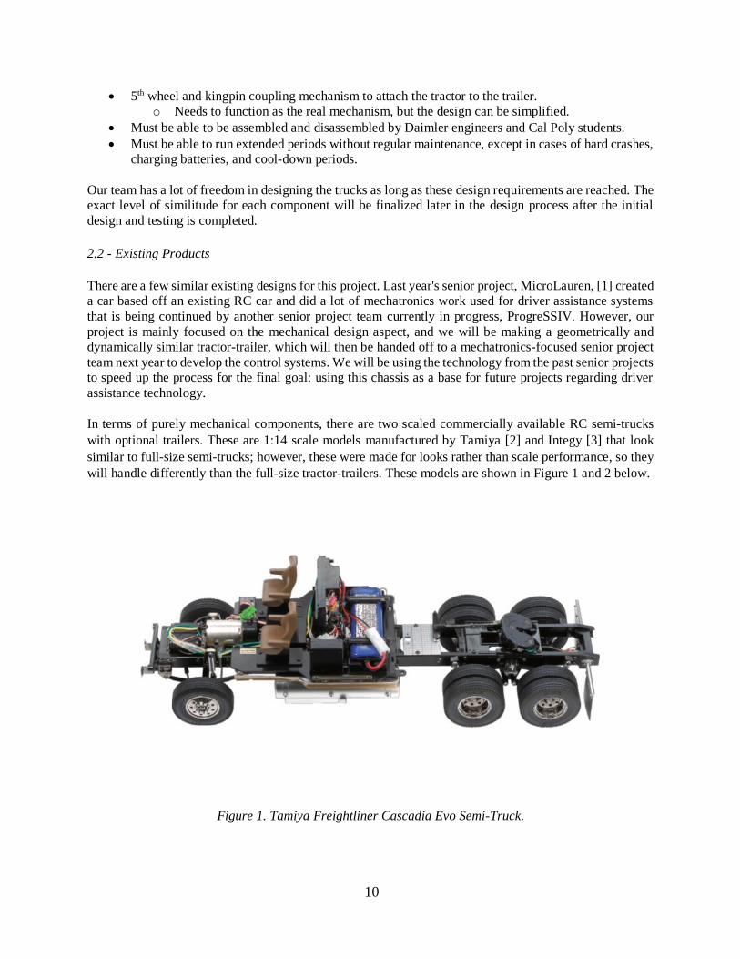
In terms of purely mechanical components, there are two scaled commercially available RC semi-trucks
with optional trailers. These are 1:14 scale models manufactured by Tamiya [2] and Integy [3] that look
similar to full-size semi-trucks; however, these were made for looks rather than scale performance, so they
will handle differently than the full-size tractor-trailers. These models are shown in Figure 1 and 2 below.
Figure 1. Tamiya Freightliner Cascadia Evo Semi-Truck.
11
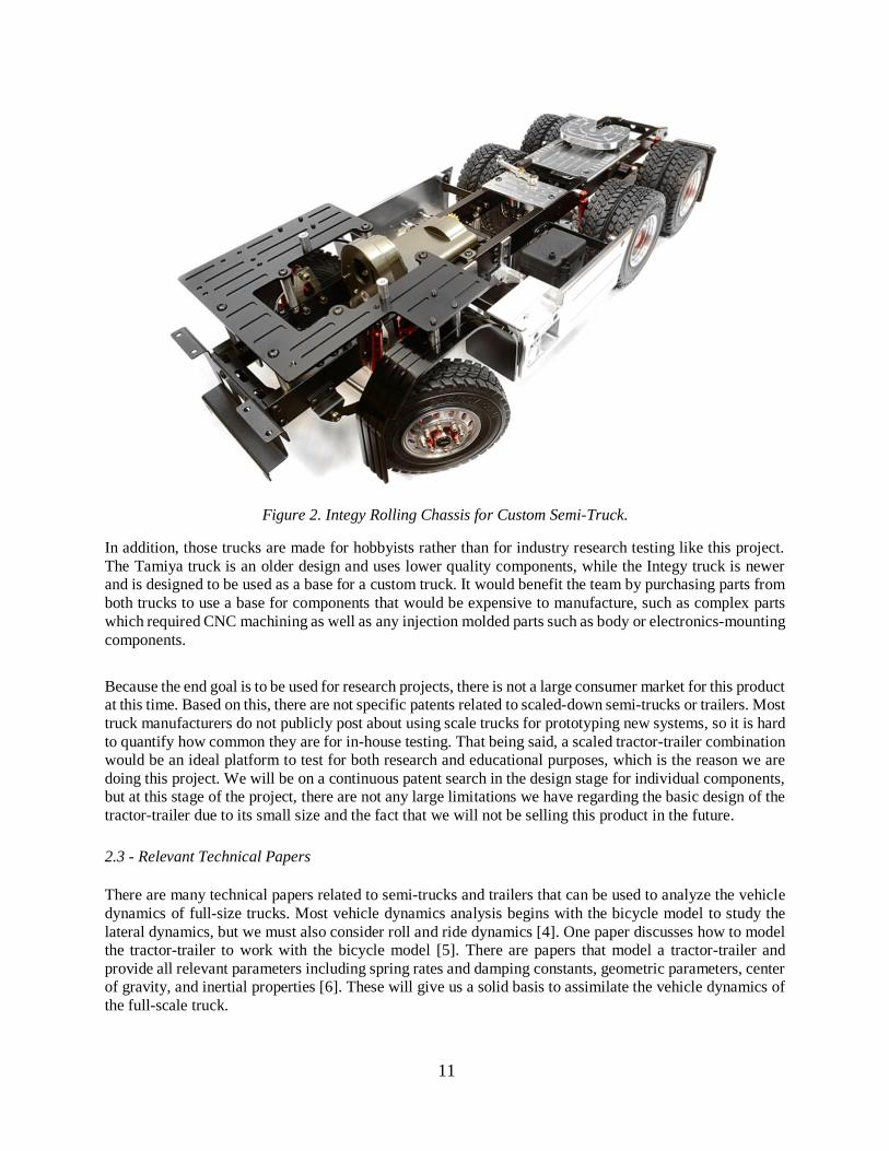
Figure 2. Integy Rolling Chassis for Custom Semi-Truck.
In addition, those trucks are made for hobbyists rather than for industry research testing like this project.
The Tamiya truck is an older design and uses lower quality components, while the Integy truck is newer
and is designed to be used as a base for a custom truck. It would benefit the team by purchasing parts from
both trucks to use a base for components that would be expensive to manufacture, such as complex parts
which required CNC machining as well as any injection molded parts such as body or electronics-mounting
components.
Because the end goal is to be used for research projects, there is not a large consumer market for this product
at this time. Based on this, there are not specific patents related to scaled-down semi-trucks or trailers. Most
truck manufacturers do not publicly post about using scale trucks for prototyping new systems, so it is hard
to quantify how common they are for in-house testing. That being said, a scaled tractor-trailer combination
would be an ideal platform to test for both research and educational purposes, which is the reason we are
doing this project. We will be on a continuous patent search in the design stage for individual components,
but at this stage of the project, there are not any large limitations we have regarding the basic design of the
tractor-trailer due to its small size and the fact that we will not be selling this product in the future.
2.3 - Relevant Technical Papers
There are many technical papers related to semi-trucks and trailers that can be used to analyze the vehicle
dynamics of full-size trucks. Most vehicle dynamics analysis begins with the bicycle model to study the
lateral dynamics, but we must also consider roll and ride dynamics [4]. One paper discusses how to model
the tractor-trailer to work with the bicycle model [5]. There are papers that model a tractor-trailer and
provide all relevant parameters including spring rates and damping constants, geometric parameters, center
of gravity, and inertial properties [6]. These will give us a solid basis to assimilate the vehicle dynamics of
the full-scale truck.
12
On the other hand, there is much less research done on similitude for vehicle applications because it is not
a common research topic. One relevant paper was a master’s thesis for a vehicle dynamics engineer
currently working at Daimler Trucks—Andrew Liburdi. Liburdi’s thesis modeled a RC monster truck,
determined similitude from a standard car, and used this as a base for the rest of his mechatronics-based
project [7]. Another master’s thesis had a similar topic, but they went further to quantify tire cornering
stiffness values for a RC plane tire [8].
Most of the similitude research papers are directly related to dimensional analysis in fluid mechanics, but
some information can be extracted for our use. We can use Buckingham-Pi dimensionless analysis with
several pi groups to determine similitude. This is discussed in detail in the Design Development section of
the paper. One notable similitude constant are quantities such as length or width are scaled linearly by [L],
area is scaled by the square [L2], volume scaled by the cubic [L3].
We will start off by scaling the linear parameters such as length to determine the wheelbase, track width,
suspension geometry, steering radius, overall weight, and center of mass. Then we will continue scaling
using more complex methods for considerations such as vibrations and spring-damper analysis. We will be
using vehicle dynamics concepts and equations discussed in the Design Development section as a base for
the pi groups in our Buckingham-Pi analysis, allowing us to get the closest level of similitude between the
real truck and our model. The most important parameters will be inertial properties, roll frequency,
cornering stiffness, and the geometric overall dimensions such as wheelbase, track width, and 5th wheel
location. After determining the initial design, we will attempt to test the geometry on a prototype truck with
accelerometers and inertial measurement units, and determine the accuracy of our similitude and vehicle
dynamics modeling. The goal is to obtain a close level (within 5% to 20% at this stage) of geometric,
kinematic, and dynamic similitude.
13
3. Objectives
3.1 - Problem Statement
Daimler Trucks is a semi-truck manufacturer that is producing new fleets with driver assistance technology,
which will allow for safer roads and reduced shipping costs. They need a way to test these features in a
controlled, small-scale environment to reduce risks associated with testing on public roads. We need to
design and manufacture a scaled-down tractor-trailer model that offers a certain level of similitude to the
full scale semi-truck and trailer combinations to provide accurate testing. This truck will also allow new
Daimler engineers and interns to apply new concepts in a low-cost and safe environment.
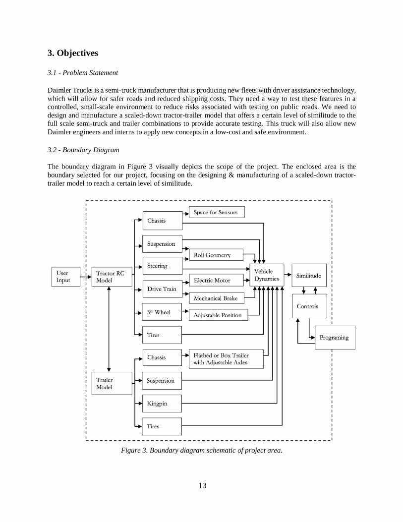
3.2 - Boundary Diagram
The boundary diagram in Figure 3 visually depicts the scope of the project. The enclosed area is the
boundary selected for our project, focusing on the designing & manufacturing of a scaled-down tractor-
trailer model to reach a certain level of similitude.
Figure 3. Boundary diagram schematic of project area.
14
3.3 - Sponsor Needs & Wants
Per Daimler’s initial requests for the project, we have determined a set of wants and needs, which is listed
in Section 2.1: Customer Needs. In addition to this, we have listed some possible desires or wants for the
model and logistical considerations for the project below:
• Mass
o Ability to attach and distribute weights in the trailer and tractor in order to change center
of mass and different trailer carrying loads
• Trailer
o The ability to alternate between a flatbed trailer and a box trailer
• Code
o Adaptability to MATLAB code
• Quality Control
o Repeatability and reliability of the parts and controls.
• Transport
o Portable enough to fit inside a standard size car.
o Needs to be able to be shipped to Daimler Trucks in Portland, OR.
• Costs
o Our total budget is $7000, but $1000 will be devoted to travel and shipping costs.
• Schedules
o Our schedule will follow the Senior Project schedule.
• Near the end of the project, we will take the completed tractor-trailer combinations to give our Final
Design Presentation at Daimler Trucks in Portland, Oregon.
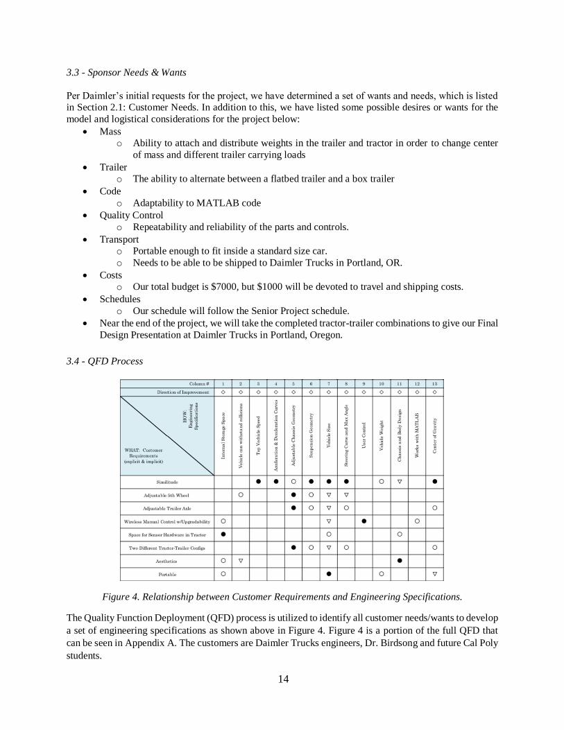
3.4 - QFD Process
Figure 4. Relationship between Customer Requirements and Engineering Specifications.
The Quality Function Deployment (QFD) process is utilized to identify all customer needs/wants to develop
a set of engineering specifications as shown above in Figure 4. Figure 4 is a portion of the full QFD that
can be seen in Appendix A. The customers are Daimler Trucks engineers, Dr. Birdsong and future Cal Poly
students.
15
The left column shows a list of customer wants, and top row describes engineering specifications needed
to meet those needs of the customer.
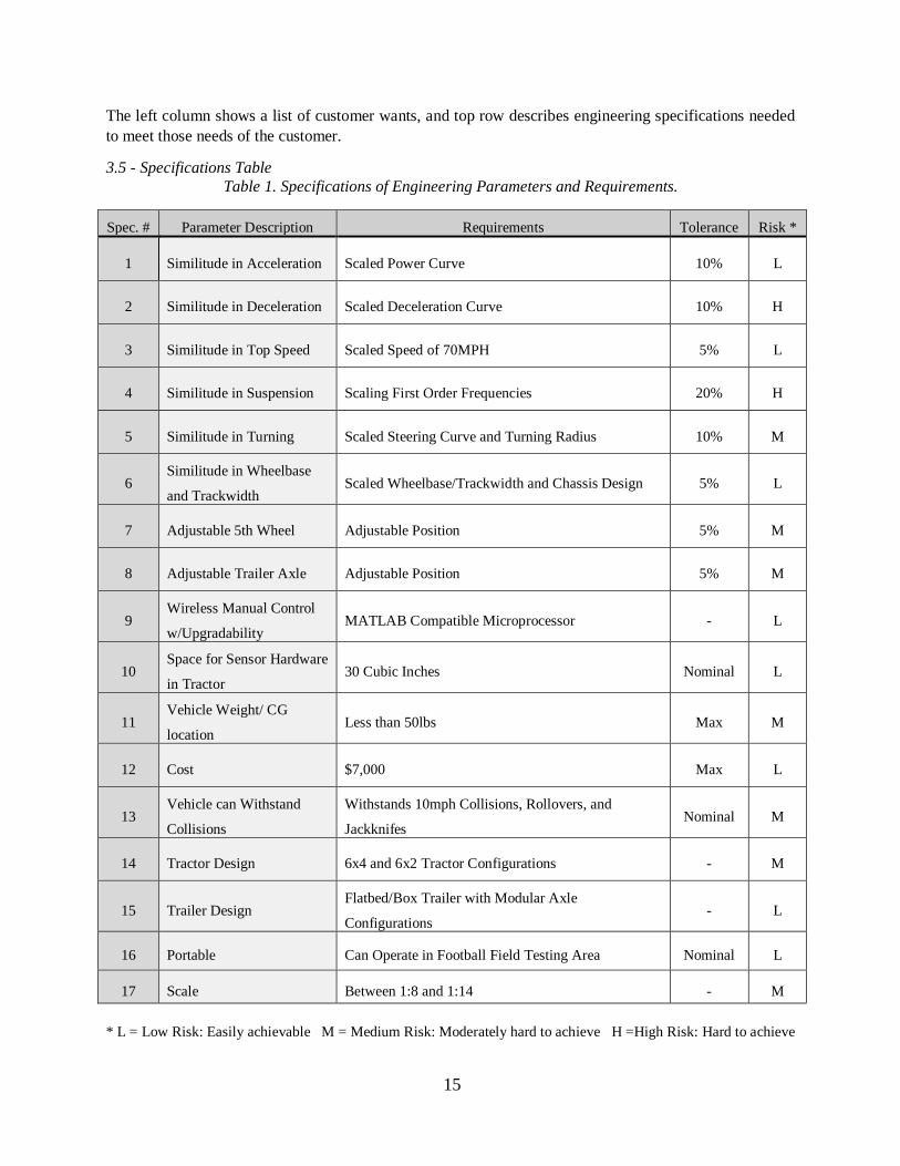
3.5 - Specifications Table
Table 1. Specifications of Engineering Parameters and Requirements.
Spec. # Parameter Description Requirements Tolerance Risk *
1 Similitude in Acceleration Scaled Power Curve 10% L
2 Similitude in Deceleration Scaled Deceleration Curve 10% H
3 Similitude in Top Speed Scaled Speed of 70MPH 5% L
4 Similitude in Suspension Scaling First Order Frequencies 20% H
5 Similitude in Turning Scaled Steering Curve and Turning Radius 10% M
6 Similitude in Wheelbase
and Trackwidth Scaled Wheelbase/Trackwidth and Chassis Design 5% L
7 Adjustable 5th Wheel Adjustable Position 5% M
8 Adjustable Trailer Axle Adjustable Position 5% M
9 Wireless Manual Control
w/Upgradability MATLAB Compatible Microprocessor - L
10 Space for Sensor Hardware
in Tractor 30 Cubic Inches Nominal L
11 Vehicle Weight/ CG
location Less than 50lbs Max M
12 Cost $7,000 Max L
13 Vehicle can Withstand
Collisions
Withstands 10mph Collisions, Rollovers, and
Jackknifes Nominal M
14 Tractor Design 6x4 and 6x2 Tractor Configurations - M
15 Trailer Design Flatbed/Box Trailer with Modular Axle
Configurations - L
16 Portable Can Operate in Football Field Testing Area Nominal L
17 Scale Between 1:8 and 1:14 - M
* L = Low Risk: Easily achievable M = Medium Risk: Moderately hard to achieve H =High Risk: Hard to achieve
16
3.5.1 - Similitude of Acceleration
One of the first needs of the sponsor is to simulate the acceleration curves of a full-scale semi-truck. We
are going to tune the controls of the motor's acceleration to make the acceleration curve of the tractor scaled
down to 1/14th the scale of a real tractor. We will need to simulate a full-size tractor from 0 to 70mph,
which is 18.7mph in 1/14 scale. The tolerance of 10% shows how far off our curve can be while still being
able to get accurate testing data from the model. This is low risk because the motor we will be using can
accelerate much faster than an actual tractor, and it will be straightforward to tune the controls to simulate
an actual tractor acceleration curve.
3.5.2 - Similitude of Deceleration
A second need from our sponsor is to simulate a scaled deceleration curve similar to the acceleration curve.
That being said, braking is much harder to do accurately with controls. There are three different braking
mechanisms on the full-scale model: engine braking, air braking, and a parking brake. For our scaled down
model, we will be able to do a control algorithm to simulate all aspects of braking. This similitude feature
will also have a 10% tolerance because it is needed for testing on road maneuvers. This is high risk because
this is harder to simulate due to the fundamentally different brake mechanisms.
3.5.3 - Similitude of Top Speed
Simulating top speed is another sponsor need that will be an easy task to accomplish because the motor we
will be selecting will easily have sufficient power to surpass the necessary top speed. Therefore, all we need
to do is to apply a speed limiter in the controls to keep the maximum speed around the scaled top speed of
19mph. Calculations for this 19mph scaled top speed are shown in Appendix B. The tolerance and risk are
both low because limiting the top speed can be done quickly.
3.5.4 - Similitude of Suspension
Suspension is a complex topic in the full-scale model because there are four leaf springs and six dampers
on the tractor, and another two leaf springs as well as four dampers on the trailer. Another sponsor need is
to scale down the first order frequency response of the suspension for our model. This aspect of the project
is going to be very hard to accurately achieve; therefore, our tolerance is 20%. This is also a high risk
because a lot of variables go into the similitude calculations and will be hard to accurately simulate.
3.5.5 - Similitude of Steering
Steering is another complex aspect because most RC semi-trucks use foam-filled rubber wheels that are
very different from the full-scale rubber air filled tires. This is an important part of the car as the tires are
the only point of contact that the tractor makes with the road. We will be testing tires to be able to accurately
simulate the steering and traction characteristics of the tractor.
The yaw angle and steering angle must be the same on the scale truck as the full-size truck; these angles do
not change with scale because the angles are dimensionless. This aspect will be moderately hard to do
because we will be purchasing the steering mechanism and adjusting it to have an accurate steering curve.
17
3.5.6 - Similitude of Wheel Base / Track Width
Similitude for geometric properties such as wheel base and track width are straightforward as they scale
linearly. These geometric properties are simply scaled measurements that will be easily implemented in
our model, and therefore have a low tolerance and risk to them.
3.5.7 - Adjustable 5th Wheel
An adjustable 5th wheel is required for this project so the tractor-trailer combination will replicate the
geometry of a full-scale tractor, where it can adjust the 5th wheel in order to change its overall wheel base.
The current design works well for full-scale vehicles, but becomes small and intricate for our scale. This
needs to be redesigned in order to rigidly hold the trailer to the tractor and preserve some of the degrees of
freedom that the full-scale design has. This is not difficult, but could fail and cause damage to the tractor
and trailer if not designed correctly; therefore, there is a moderate risk associated with it.
3.5.8 - Adjustable Trailer Axles
Trailers have a wide range of axle configurations because the cargo weight is loaded in various
configurations, so an adjustable and modular axle system is needed to account for different loading
scenarios. This is simple to accomplish because of the long trailer chassis, allowing us to have multiple
locations to mount the trailer axles to allow for adjustability. This aspect is low risk.
3.5.9 - Wireless Manual Control with Upgradability
The vehicle needs to be wirelessly controlled using a RC car controller. A microcontroller will be used to
wirelessly control the motor and therefore control acceleration, deceleration, top speed, and steering. This
will be easy to implement as we are well versed in microcontrollers and will be able to integrate wireless
control into our model. The risk for this is low and should not be a problem.
3.5.10 - Space for Sensor Hardware in Tractor
One of the goals for this project is to be able to test driver assistance features which will require multiple
sensors, microcontrollers and other electronic components. We need to allow for space for these electronic
components and make mounts for the sensors in order for future modifications to the controls. The risk for
this is low because there are large amounts of cab space in the tractor.
3.5.11 - Vehicle Weight / CG location
Vehicle weight has a straightforward scaling formula and will be simple to figure out and adjust. We would
likely add weight in places to get the scaled weight the same, while maintaining the scale inertial and center
of gravity properties.
18
3.5.12 – Cost
The budget for our project is $7000 with a rough estimate of around $1000 for shipping of the model and
traveling to Portland, Oregon. This limits our budget to around $6000 for out-sourced parts, material for in-
house manufacturing, and electronic components, as well as testing components and facility-use fees. This
is a low risk aspect, but we will know more once we go into to the cost analysis phase of the project.
3.5.13 - Vehicle Can Withstand Collisions
The vehicle must be able to withstand low speed collisions, rollovers, and jackknifes. Out model will be
mostly made from aluminum and steel parts and should be strong enough to fulfill these requirements as
long as the design is robust. This is a moderate risk because if the parts break easily, it could be detrimental
to our project. Because of this, we will do analysis and take precautionary methods to ensure that this
requirement will be met.
3.5.14 - Tractor Design
The two desired configurations for the tractor design requested by our sponsor are a 6x4 and a 6x2 tractor.
This means a 6-wheel, 4 driven wheel configuration and a 6-wheel, 2 driven wheel configuration. This will
be achieved by creating a 6x4 configuration with the option to detach the rear center drive shaft to the
second axle in order to allow for adjustability from a 6x4 configuration to a 6x2 configuration. With this
ability we may, depending on time constraints, be able to make a second tractor with a 4x2 configuration.
3.5.15 - Trailer Design
The trailer must be a convertible box to flatbed design. This is a low risk aspect of the project and will be
able to be achieved without problems due to its simplicity.
3.5.16 - Portability
This model needs to be of reasonable size so that we will be able to ship is to Daimler's facility in Portland,
Oregon. This is not an issue because of the small size of the tractor-trailer, so it is low risk.
3.5.17 - Scale
We must select a reasonable scale for our model so we can easily test and ship this model while still being
large enough to be able to manufacture parts for it. This should be low risk as current products and parts
are around 1/12th to 1/14th scale that we will need to outsource parts for.
19
4. Conceptual Design Development
Before going into our design concepts, vehicle dynamics and similitude must be first discussed in detail
because every component will be designed with them in mind.
4.1 - Vehicle Dynamics
To create similar handling characteristics with the tractor-trailer, we must first understand vehicle
dynamics. This subject can get complex extremely quickly, but we will start off with the basics. Vehicle
dynamics can be split into two main categories: lateral dynamics and ride dynamics. Lateral dynamics deals
with how the vehicle handles throughout corners—which can be split into a bicycle model and roll
dynamics. Ride dynamics deals with the ride characteristics when driving on a straight road.
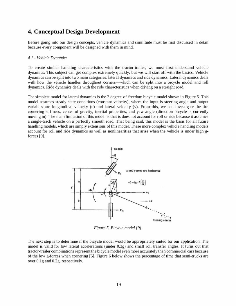
The simplest model for lateral dynamics is the 2 degree-of-freedom bicycle model shown in Figure 5. This
model assumes steady state conditions (constant velocity), where the input is steering angle and output
variables are longitudinal velocity (u) and lateral velocity (v). From this, we can investigate the tire
cornering stiffness, center of gravity, inertial properties, and yaw angle (direction bicycle is currently
moving in). The main limitation of this model is that is does not account for roll or ride because it assumes
a single-track vehicle on a perfectly smooth road. That being said, this model is the basis for all future
handling models, which are simply extensions of this model. These more complex vehicle handling models
account for roll and ride dynamics as well as nonlinearities that arise when the vehicle is under high g-
forces [9].
Figure 5. Bicycle model [9].
The next step is to determine if the bicycle model would be appropriately suited for our application. The
model is valid for low lateral accelerations (under 0.3g) and small roll transfer angles. It turns out that
tractor-trailer combinations represent the bicycle model even more accurately than commercial cars because
of the low g-forces when cornering [5]. Figure 6 below shows the percentage of time that semi-trucks are
over 0.1g and 0.2g, respectively.
20
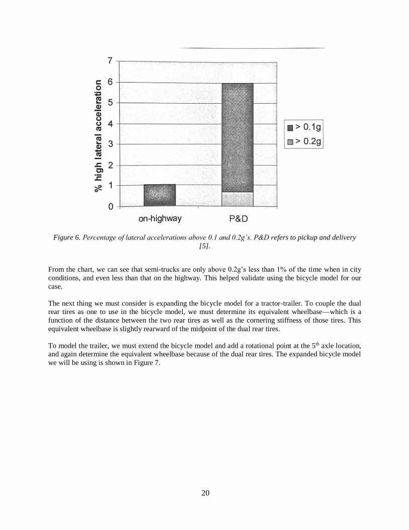
Figure 6. Percentage of lateral accelerations above 0.1 and 0.2g’s. P&D refers to pickup and delivery
[5].
From the chart, we can see that semi-trucks are only above 0.2g’s less than 1% of the time when in city
conditions, and even less than that on the highway. This helped validate using the bicycle model for our
case.
The next thing we must consider is expanding the bicycle model for a tractor-trailer. To couple the dual
rear tires as one to use in the bicycle model, we must determine its equivalent wheelbase—which is a
function of the distance between the two rear tires as well as the cornering stiffness of those tires. This
equivalent wheelbase is slightly rearward of the midpoint of the dual rear tires.
To model the trailer, we must extend the bicycle model and add a rotational point at the 5th axle location,
and again determine the equivalent wheelbase because of the dual rear tires. The expanded bicycle model
we will be using is shown in Figure 7.
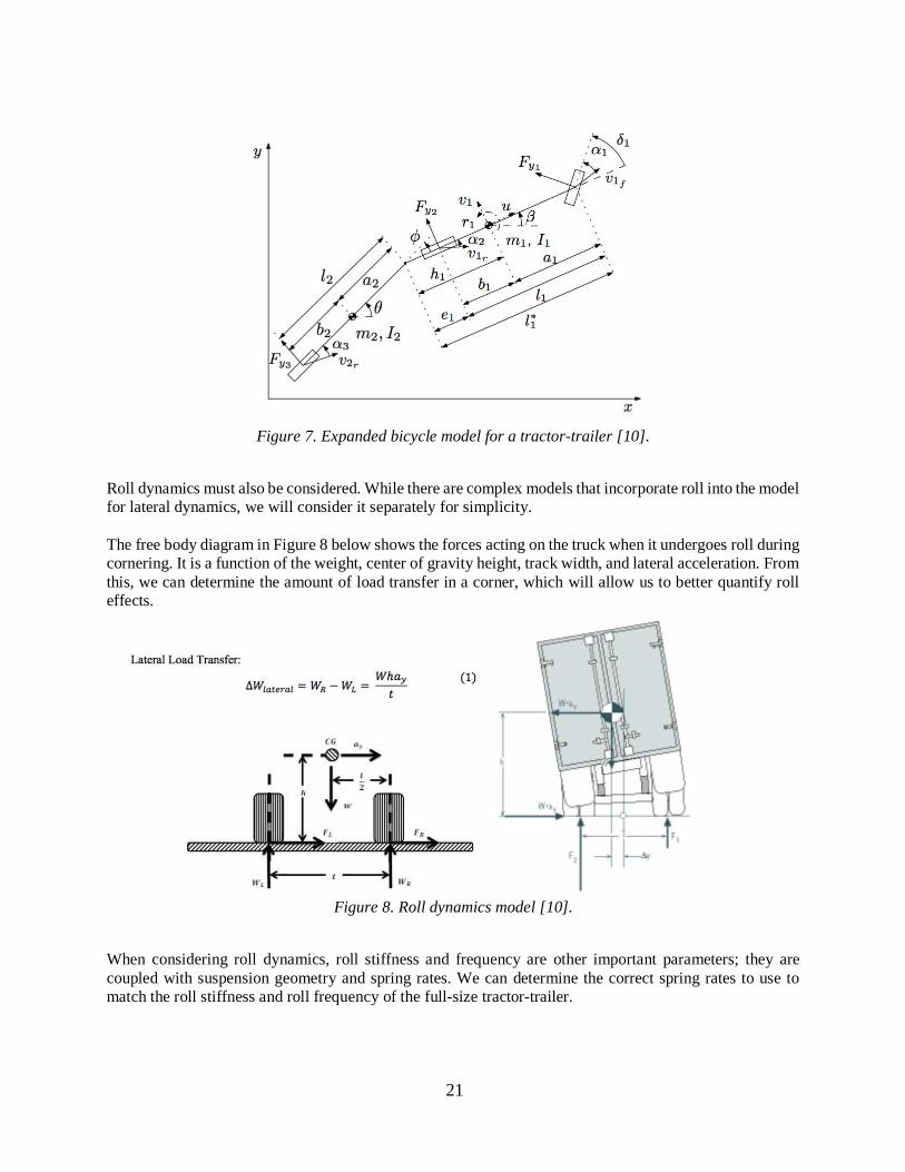
21
Figure 7. Expanded bicycle model for a tractor-trailer [10].
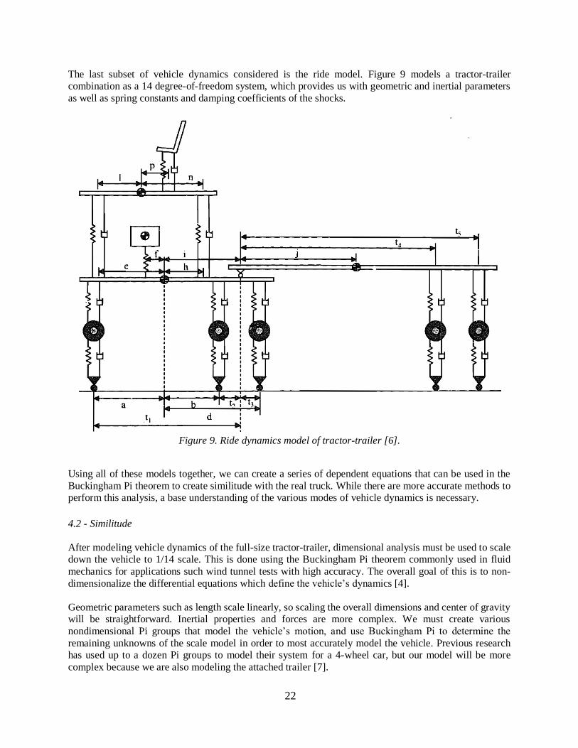
Roll dynamics must also be considered. While there are complex models that incorporate roll into the model
for lateral dynamics, we will consider it separately for simplicity.
The free body diagram in Figure 8 below shows the forces acting on the truck when it undergoes roll during
cornering. It is a function of the weight, center of gravity height, track width, and lateral acceleration. From
this, we can determine the amount of load transfer in a corner, which will allow us to better quantify roll
effects.
Figure 8. Roll dynamics model [10].
When considering roll dynamics, roll stiffness and frequency are other important parameters; they are
coupled with suspension geometry and spring rates. We can determine the correct spring rates to use to
match the roll stiffness and roll frequency of the full-size tractor-trailer.
22
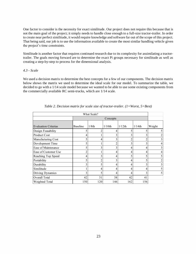
The last subset of vehicle dynamics considered is the ride model. Figure 9 models a tractor-trailer
combination as a 14 degree-of-freedom system, which provides us with geometric and inertial parameters
as well as spring constants and damping coefficients of the shocks.
Figure 9. Ride dynamics model of tractor-trailer [6].
Using all of these models together, we can create a series of dependent equations that can be used in the
Buckingham Pi theorem to create similitude with the real truck. While there are more accurate methods to
perform this analysis, a base understanding of the various modes of vehicle dynamics is necessary.
4.2 - Similitude
After modeling vehicle dynamics of the full-size tractor-trailer, dimensional analysis must be used to scale down the vehicle to 1/14 scale. This is done using the Buckingham Pi theorem commonly used in fluid
mechanics for applications such wind tunnel tests with high accuracy. The overall goal of this is to non-
dimensionalize the differential equations which define the vehicle’s dynamics [4].
Geometric parameters such as length scale linearly, so scaling the overall dimensions and center of gravity
will be straightforward. Inertial properties and forces are more complex. We must create various
nondimensional Pi groups that model the vehicle’s motion, and use Buckingham Pi to determine the
remaining unknowns of the scale model in order to most accurately model the vehicle. Previous research has used up to a dozen Pi groups to model their system for a 4-wheel car, but our model will be more
complex because we are also modeling the attached trailer [7].
23
One factor to consider is the necessity for exact similitude. Our project does not require this because that is
not the main goal of the project; it simply needs to handle close enough to a full-size tractor-trailer. In order
to create near perfect similitude, it would require knowledge and software far out of the scope of this project.
That being said, our job is to use the information available to create the most similar handling vehicle given
the project’s time constraints.
Similitude is another factor that requires continued research due to its complexity for assimilating a tractor-
trailer. The goals moving forward are to determine the exact Pi groups necessary for similitude as well as
creating a step-by-step to process for the dimensional analysis.
4.3 - Scale
We used a decision matrix to determine the best concepts for a few of our components. The decision matrix
below shows the matrix we used to determine the ideal scale for our model. To summarize the table, we
decided to go with a 1/14 scale model because we wanted to be able to use some existing components from
the commercially available RC semi-trucks, which are 1/14 scale.
Table 2. Decision matrix for scale size of tractor-trailer. (1=Worst, 5=Best)
24
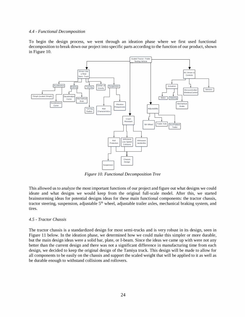
4.4 - Functional Decomposition
To begin the design process, we went through an ideation phase where we first used functional
decomposition to break down our project into specific parts according to the function of our product, shown
in Figure 10.
Figure 10. Functional Decomposition Tree
This allowed us to analyze the most important functions of our project and figure out what designs we could
ideate and what designs we would keep from the original full-scale model. After this, we started
brainstorming ideas for potential designs ideas for these main functional components: the tractor chassis,
tractor steering, suspension, adjustable 5th wheel, adjustable trailer axles, mechanical braking system, and
tires.
4.5 - Tractor Chassis
The tractor chassis is a standardized design for most semi-trucks and is very robust in its design, seen in
Figure 11 below. In the ideation phase, we determined how we could make this simpler or more durable,
but the main design ideas were a solid bar, plate, or I-beam. Since the ideas we came up with were not any
better than the current design and there was not a significant difference in manufacturing time from each
design, we decided to keep the original design of the Tamiya truck. This design will be made to allow for
all components to be easily on the chassis and support the scaled weight that will be applied to it as well as
be durable enough to withstand collisions and rollovers.
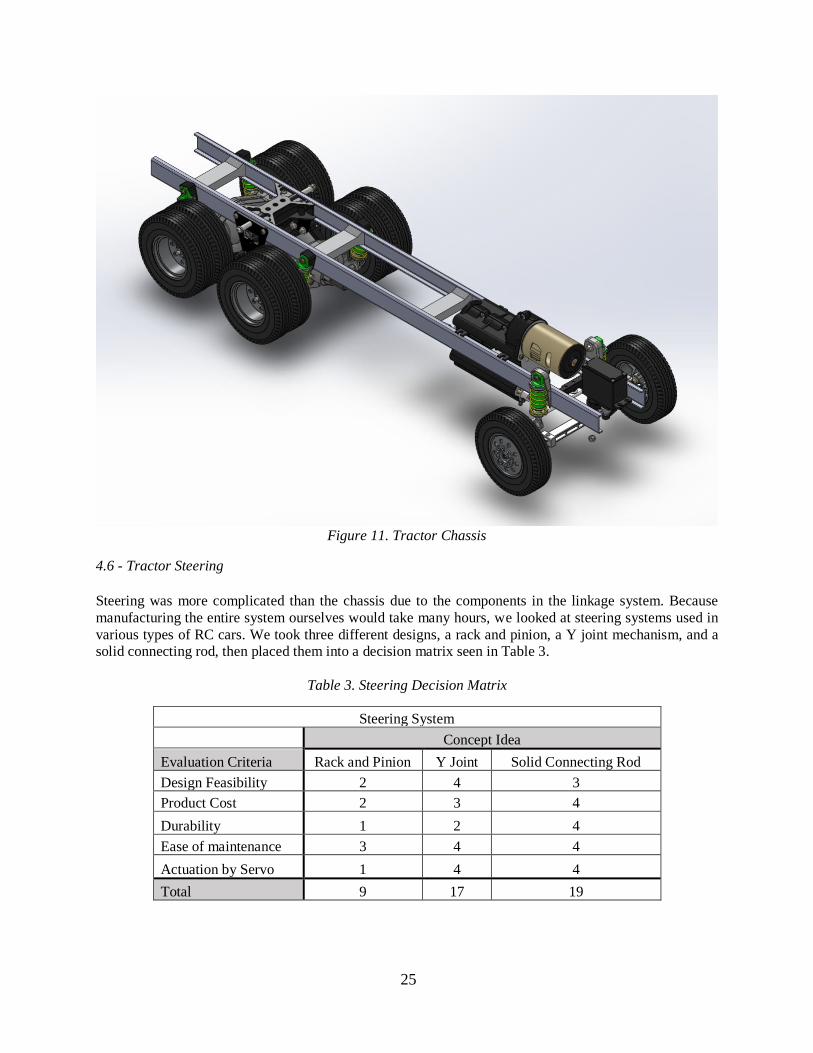
25
Figure 11. Tractor Chassis
4.6 - Tractor Steering
Steering was more complicated than the chassis due to the components in the linkage system. Because
manufacturing the entire system ourselves would take many hours, we looked at steering systems used in
various types of RC cars. We took three different designs, a rack and pinion, a Y joint mechanism, and a
solid connecting rod, then placed them into a decision matrix seen in Table 3.
Table 3. Steering Decision Matrix
Steering System
Concept Idea
Evaluation Criteria Rack and Pinion Y Joint Solid Connecting Rod
Design Feasibility 2 4 3
Product Cost 2 3 4
Durability 1 2 4
Ease of maintenance 3 4 4
Actuation by Servo 1 4 4
Total 9 17 19
26
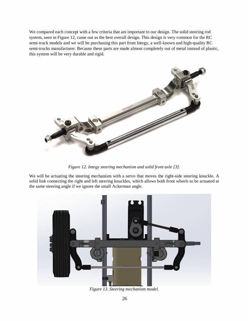
We compared each concept with a few criteria that are important to our design. The solid steering rod
system, seen in Figure 12, came out as the best overall design. This design is very common for the RC
semi-truck models and we will be purchasing this part from Integy, a well-known and high-quality RC
semi-trucks manufacturer. Because these parts are made almost completely out of metal instead of plastic,
this system will be very durable and rigid.
Figure 12. Integy steering mechanism and solid front axle [3].
We will be actuating the steering mechanism with a servo that moves the right-side steering knuckle. A
solid link connecting the right and left steering knuckles, which allows both front wheels to be actuated at
the same steering angle if we ignore the small Ackerman angle.
Figure 13. Steering mechanism model.
27
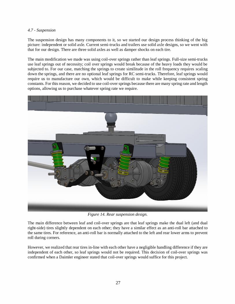
4.7 - Suspension
The suspension design has many components to it, so we started our design process thinking of the big
picture: independent or solid axle. Current semi-trucks and trailers use solid axle designs, so we went with
that for our design. There are three solid axles as well as damper shocks on each tire.
The main modification we made was using coil-over springs rather than leaf springs. Full-size semi-trucks
use leaf springs out of necessity; coil over springs would break because of the heavy loads they would be
subjected to. For our case, matching the springs to create similitude in the roll frequency requires scaling
down the springs, and there are no optional leaf springs for RC semi-trucks. Therefore, leaf springs would
require us to manufacture our own, which would be difficult to make while keeping consistent spring
constants. For this reason, we decided to use coil-over springs because there are many spring rate and length
options, allowing us to purchase whatever spring rate we require.
Figure 14. Rear suspension design.
The main difference between leaf and coil-over springs are that leaf springs make the dual left (and dual
right-side) tires slightly dependent on each other; they have a similar effect as an anti-roll bar attached to
the same tires. For reference, an anti-roll bar is normally attached to the left and rear lower arms to prevent
roll during corners.
However, we realized that rear tires in-line with each other have a negligible handling difference if they are
independent of each other, so leaf springs would not be required. This decision of coil-over springs was
confirmed when a Daimler engineer stated that coil-over springs would suffice for this project.
28
4.8 - Drivetrain
We started our concept development by determining what differentials and other drivetrain components
could be purchased and their applications. The differentials used require CNC machining because of the
small gears and complex shapes, which would take weeks to be produced at Cal Poly. For our case, we
realized that designing and manufacturing the differentials would take much more time than would be
gained, so purchasing and modifying was the best option.
We purchased and modified most of the drivetrain components due to the manufacturing complexity of the
small gears and differentials. We purchased a set of two differentials which allows us to make the tractor
modular between a 6x2 and 6x4 simply by attaching the center driveshaft that connects the differentials.
The Tamiya differential was also considered because they are slightly less expensive at $90 per differential,
but is lower quality and used many plastic components.
Figure 15. Integy dual rear differentials [3].
The track width must be correctly scaled down from the real truck, and these parts would result in a 180mm
track width whereas the 1:14 scale equivalent of the 2.5m truck track width is 179mm. This is well within
10% tolerance.
The dog bone used to transmit power from the gearbox to the rear axles, shown in Figure 16, may be
machined because of the custom wheelbase. We will use a lathe to turn the steel to a proper diameter, then
press fit a pin in.
29
Figure 16. Bottom view of assembly showing the drivetrain components. The dog bone is the silver piece
in the centerline of the chassis between the gearbox and the first rear differential.
4.9 - Adjustable 5th Wheel
The 5th wheel is the connection between the tractor and trailer. For the current design of full-scale semi-
trucks, a U-coupler is used with a latching mechanism made of metal as shown in Figure 17.
Figure 17. Original concept from Tamiya truck.
This becomes very small and intricate to manufacture for our model and therefore we had to come up with
a new design. We used a few brainstorming techniques in order to populate many different ideas, so we
could then work through the ideas to the best solution. We had to make this design a rigid connection
between the tractor and trailer so there will not be any extra degrees of freedom. We also need to be able to
adjust the position of the fifth wheel longitudinally to shorten or lengthen the overall wheelbase. This
brought us to ideas such as slotted grooves in a metal bar every 15mm so that a bar could be inserted and
locked with a pin.
30
Our next concept was a sliding mechanism that uses two bolts to secure the position, as shown in Figure
18. We would then attach the 5th wheel coupler to the center hole of the slider. This mechanism will be
attached to the chassis.
Figure 18. 3D printed final concept for adjustable 5th wheel sliding mechanism.
We believed this to be the best design concept, but we used a decision matrix shown in Table 4 to confirm
our intuition.
Table 4. Decision matrix for possible 5th wheel designs.
After several ideas, we found that a pin and a slot of typical kingpin allows for the necessary degrees of
freedom with the 5th wheel connection, as a ball and socket connection would allow for too many degrees
of freedom. The coupler would be mounted on the slider that could be bolted down in various positions
with the scaled range that is desired by Daimler.
31
4.10 Trailer Chassis
The trailer chassis had to undergo various redesigns in order to meet the scale weight requirements of the
trailer. The initial design of the trailer chassis used solid bar stock with supports perpendicular to the chassis
as shown in Figure 19.
Figure 19. First Concept of the Trailer Chassis.
We realized this was not feasible after conducting a weight analysis; we found that the trailer weight was
several pounds larger than the ideal scaled weight.
This led us to the idea of using a L bracket chassis, similar to the U bracket chassis design of the tractor.
The L-bracket facing outwards allows for support of the trailer base and box. The next step was deciding
on the inner supports of the chassis to provide rigidity to the 4’ long trailer. Solid bar stock is simple, but
would add unnecessary extra weight. For this reason, we decided to use bar stock with milled out slots. The
final design is shown in Figure 20 below.
Figure 20. Final Trailer Chassis Design.
32
4.11 - Adjustable Trailer Axles
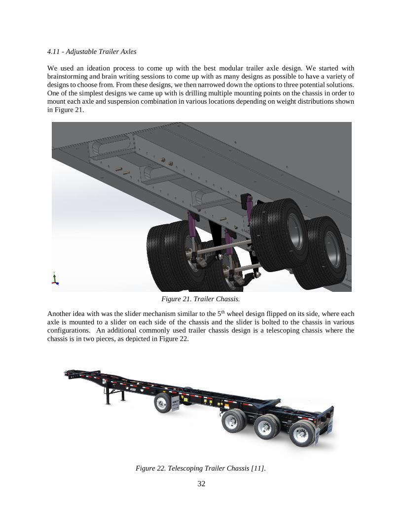
We used an ideation process to come up with the best modular trailer axle design. We started with
brainstorming and brain writing sessions to come up with as many designs as possible to have a variety of
designs to choose from. From these designs, we then narrowed down the options to three potential solutions.
One of the simplest designs we came up with is drilling multiple mounting points on the chassis in order to
mount each axle and suspension combination in various locations depending on weight distributions shown
in Figure 21.
Figure 21. Trailer Chassis.
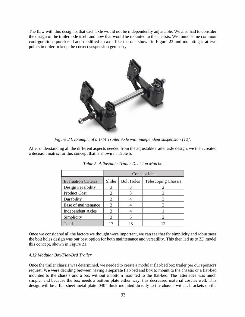
Another idea with was the slider mechanism similar to the 5th wheel design flipped on its side, where each
axle is mounted to a slider on each side of the chassis and the slider is bolted to the chassis in various
configurations. An additional commonly used trailer chassis design is a telescoping chassis where the
chassis is in two pieces, as depicted in Figure 22.
Figure 22. Telescoping Trailer Chassis [11].
33
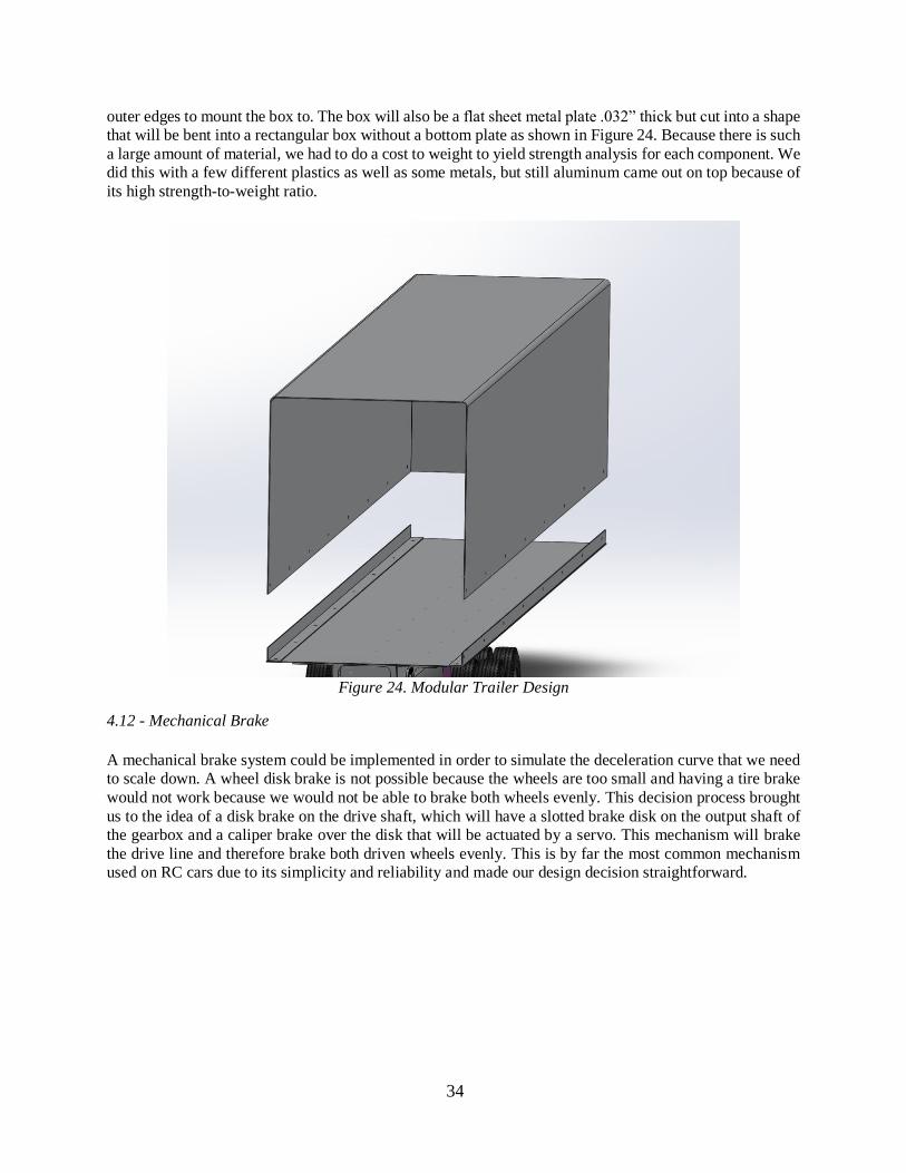
The flaw with this design is that each axle would not be independently adjustable. We also had to consider
the design of the trailer axle itself and how that would be mounted to the chassis. We found some common
configurations purchased and modified an axle like the one shown in Figure 23 and mounting it at two
points in order to keep the correct suspension geometry.
Figure 23. Example of a 1/14 Trailer Axle with independent suspension [12].
After understanding all the different aspects needed from the adjustable trailer axle design, we then created
a decision matrix for this concept that is shown in Table 5.
Table 5. Adjustable Trailer Decision Matrix.
Concept Idea
Evaluation Criteria Slider Bolt Holes Telescoping Chassis
Design Feasibility 3 3 2
Product Cost 2 3 2
Durability 3 4 3
Ease of maintenance 3 4 2
Independent Axles 3 4 1
Simplicity 3 5 2
Total 17 23 12
Once we considered all the factors we thought were important, we can see that for simplicity and robustness
the bolt holes design was our best option for both maintenance and versatility. This then led us to 3D model
this concept, shown in Figure 21.
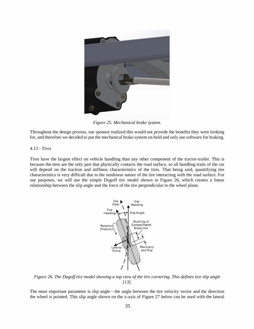
4.12 Modular Box/Flat-Bed Trailer
Once the trailer chassis was determined, we needed to create a modular flat-bed box trailer per our sponsors
request. We were deciding between having a separate flat-bed and box to mount to the chassis or a flat-bed
mounted to the chassis and a box without a bottom mounted to the flat-bed. The latter idea was much simpler and because the box needs a bottom plate either way, this decreased material cost as well. This
design will be a flat sheet metal plate .040” thick mounted directly to the chassis with L-brackets on the
34
outer edges to mount the box to. The box will also be a flat sheet metal plate .032” thick but cut into a shape
that will be bent into a rectangular box without a bottom plate as shown in Figure 24. Because there is such
a large amount of material, we had to do a cost to weight to yield strength analysis for each component. We
did this with a few different plastics as well as some metals, but still aluminum came out on top because of
its high strength-to-weight ratio.
Figure 24. Modular Trailer Design
4.12 - Mechanical Brake
A mechanical brake system could be implemented in order to simulate the deceleration curve that we need
to scale down. A wheel disk brake is not possible because the wheels are too small and having a tire brake
would not work because we would not be able to brake both wheels evenly. This decision process brought
us to the idea of a disk brake on the drive shaft, which will have a slotted brake disk on the output shaft of
the gearbox and a caliper brake over the disk that will be actuated by a servo. This mechanism will brake
the drive line and therefore brake both driven wheels evenly. This is by far the most common mechanism
used on RC cars due to its simplicity and reliability and made our design decision straightforward.
35
Figure 25. Mechanical brake system.
Throughout the design process, our sponsor realized this would not provide the benefits they were looking
for, and therefore we decided to put the mechanical brake system on hold and only use software for braking.
4.13 - Tires
Tires have the largest effect on vehicle handling than any other component of the tractor-trailer. This is
because the tires are the only part that physically contacts the road surface, so all handling traits of the car
will depend on the traction and stiffness characteristics of the tires. That being said, quantifying tire
characteristics is very difficult due to the nonlinear nature of the tire interacting with the road surface. For
our purposes, we will use the simple Dugoff tire model shown in Figure 26, which creates a linear
relationship between the slip angle and the force of the tire perpendicular to the wheel plane.
Figure 26. The Dugoff tire model showing a top view of the tire cornering. This defines tire slip angle
[13].
The most important parameter is slip angle—the angle between the tire velocity vector and the direction
the wheel is pointed. This slip angle shown on the x-axis of Figure 27 below can be used with the lateral
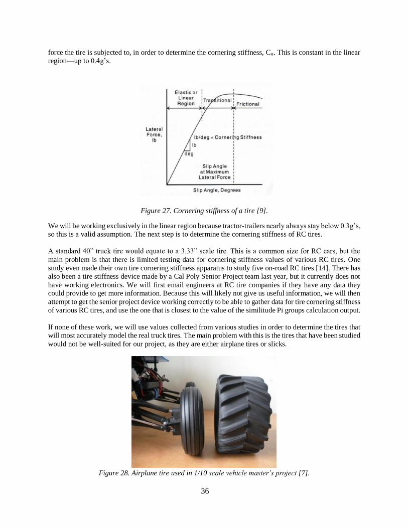
36
force the tire is subjected to, in order to determine the cornering stiffness, Cα. This is constant in the linear
region—up to 0.4g’s.
Figure 27. Cornering stiffness of a tire [9].
We will be working exclusively in the linear region because tractor-trailers nearly always stay below 0.3g’s,
so this is a valid assumption. The next step is to determine the cornering stiffness of RC tires.
A standard 40” truck tire would equate to a 3.33” scale tire. This is a common size for RC cars, but the
main problem is that there is limited testing data for cornering stiffness values of various RC tires. One
study even made their own tire cornering stiffness apparatus to study five on-road RC tires [14]. There has
also been a tire stiffness device made by a Cal Poly Senior Project team last year, but it currently does not
have working electronics. We will first email engineers at RC tire companies if they have any data they
could provide to get more information. Because this will likely not give us useful information, we will then
attempt to get the senior project device working correctly to be able to gather data for tire cornering stiffness
of various RC tires, and use the one that is closest to the value of the similitude Pi groups calculation output.
If none of these work, we will use values collected from various studies in order to determine the tires that
will most accurately model the real truck tires. The main problem with this is the tires that have been studied
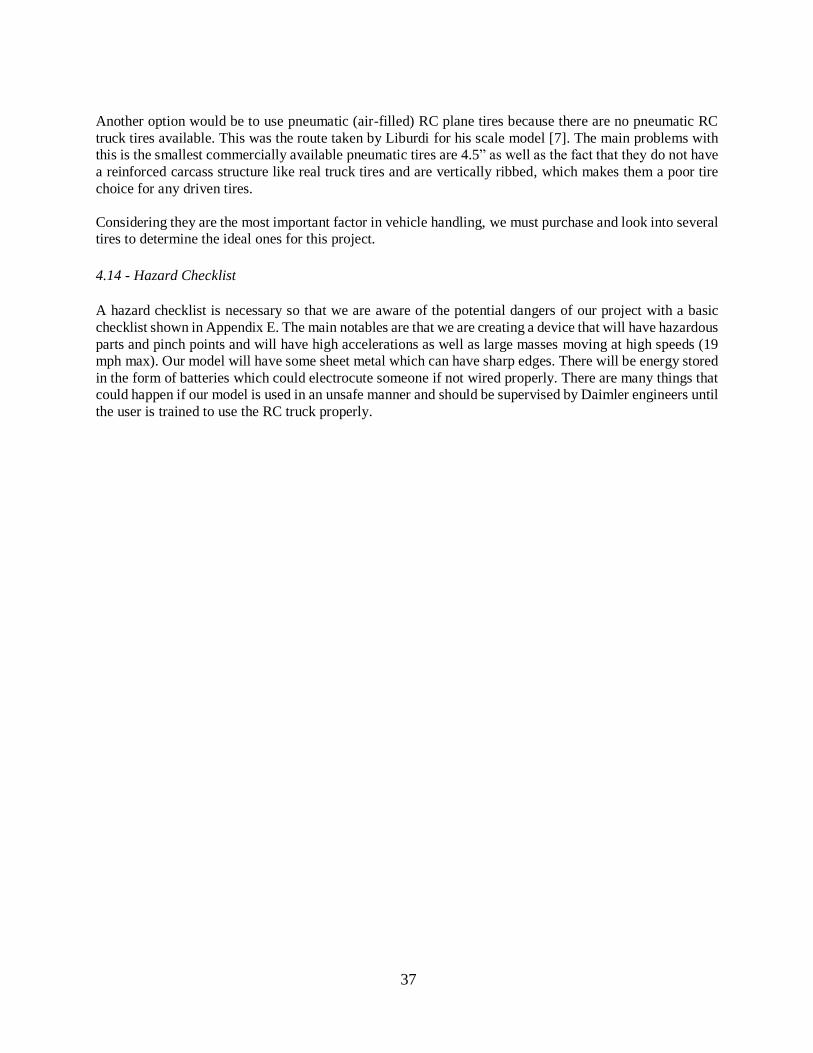
would not be well-suited for our project, as they are either airplane tires or slicks.
Figure 28. Airplane tire used in 1/10 scale vehicle master’s project [7].
37
Another option would be to use pneumatic (air-filled) RC plane tires because there are no pneumatic RC
truck tires available. This was the route taken by Liburdi for his scale model [7]. The main problems with
this is the smallest commercially available pneumatic tires are 4.5” as well as the fact that they do not have
a reinforced carcass structure like real truck tires and are vertically ribbed, which makes them a poor tire
choice for any driven tires.
Considering they are the most important factor in vehicle handling, we must purchase and look into several
tires to determine the ideal ones for this project.
4.14 - Hazard Checklist
A hazard checklist is necessary so that we are aware of the potential dangers of our project with a basic
checklist shown in Appendix E. The main notables are that we are creating a device that will have hazardous
parts and pinch points and will have high accelerations as well as large masses moving at high speeds (19
mph max). Our model will have some sheet metal which can have sharp edges. There will be energy stored
in the form of batteries which could electrocute someone if not wired properly. There are many things that
could happen if our model is used in an unsafe manner and should be supervised by Daimler engineers until
the user is trained to use the RC truck properly.
38
5. Final Design
5.1 Tractor Design
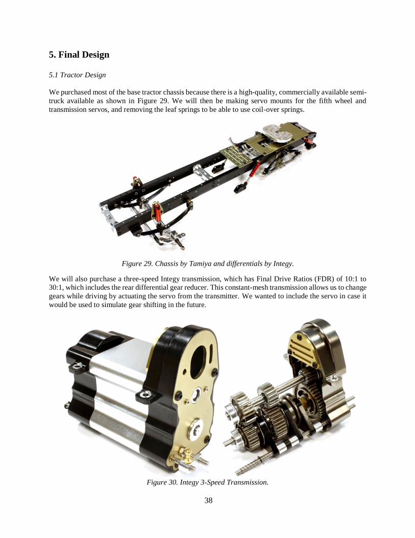
We purchased most of the base tractor chassis because there is a high-quality, commercially available semi-
truck available as shown in Figure 29. We will then be making servo mounts for the fifth wheel and
transmission servos, and removing the leaf springs to be able to use coil-over springs.
Figure 29. Chassis by Tamiya and differentials by Integy.
We will also purchase a three-speed Integy transmission, which has Final Drive Ratios (FDR) of 10:1 to
30:1, which includes the rear differential gear reducer. This constant-mesh transmission allows us to change
gears while driving by actuating the servo from the transmitter. We wanted to include the servo in case it
would be used to simulate gear shifting in the future.
Figure 30. Integy 3-Speed Transmission.
39
5.2 Fifth Wheel Design
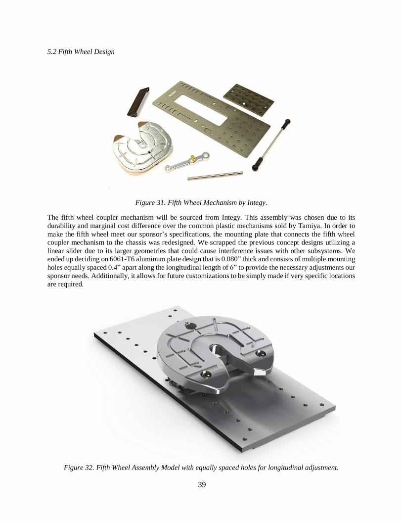
Figure 31. Fifth Wheel Mechanism by Integy.
The fifth wheel coupler mechanism will be sourced from Integy. This assembly was chosen due to its
durability and marginal cost difference over the common plastic mechanisms sold by Tamiya. In order to
make the fifth wheel meet our sponsor’s specifications, the mounting plate that connects the fifth wheel
coupler mechanism to the chassis was redesigned. We scrapped the previous concept designs utilizing a
linear slider due to its larger geometries that could cause interference issues with other subsystems. We
ended up deciding on 6061-T6 aluminum plate design that is 0.080” thick and consists of multiple mounting
holes equally spaced 0.4” apart along the longitudinal length of 6” to provide the necessary adjustments our
sponsor needs. Additionally, it allows for future customizations to be simply made if very specific locations
are required.
Figure 32. Fifth Wheel Assembly Model with equally spaced holes for longitudinal adjustment.
40
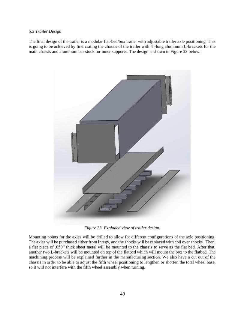
5.3 Trailer Design
The final design of the trailer is a modular flat-bed/box trailer with adjustable trailer axle positioning. This
is going to be achieved by first crating the chassis of the trailer with 4’-long aluminum L-brackets for the
main chassis and aluminum bar stock for inner supports. The design is shown in Figure 33 below.
Figure 33. Exploded view of trailer design.
Mounting points for the axles will be drilled to allow for different configurations of the axle positioning.
The axles will be purchased either from Integy, and the shocks will be replaced with coil over shocks. Then,
a flat piece of .050” thick sheet metal will be mounted to the chassis to serve as the flat bed. After that,
another two L-brackets will be mounted on top of the flatbed which will mount the box to the flatbed. The
machining process will be explained further in the manufacturing section. We also have a cut out of the
chassis in order to be able to adjust the fifth wheel positioning to lengthen or shorten the total wheel base,
so it will not interfere with the fifth wheel assembly when turning.
41
5.4 Shocks
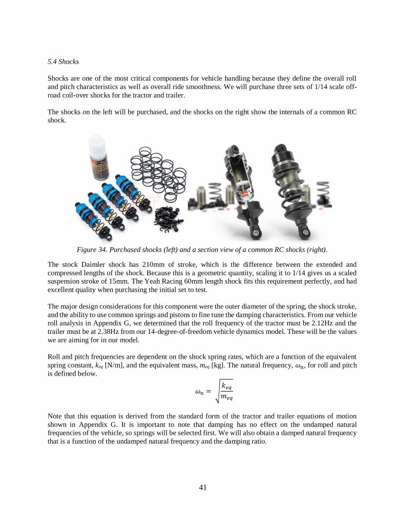
Shocks are one of the most critical components for vehicle handling because they define the overall roll
and pitch characteristics as well as overall ride smoothness. We will purchase three sets of 1/14 scale off-
road coil-over shocks for the tractor and trailer.
The shocks on the left will be purchased, and the shocks on the right show the internals of a common RC
shock.
Figure 34. Purchased shocks (left) and a section view of a common RC shocks (right).
The stock Daimler shock has 210mm of stroke, which is the difference between the extended and
compressed lengths of the shock. Because this is a geometric quantity, scaling it to 1/14 gives us a scaled
suspension stroke of 15mm. The Yeah Racing 60mm length shock fits this requirement perfectly, and had
excellent quality when purchasing the initial set to test.
The major design considerations for this component were the outer diameter of the spring, the shock stroke,
and the ability to use common springs and pistons to fine tune the damping characteristics. From our vehicle
roll analysis in Appendix G, we determined that the roll frequency of the tractor must be 2.12Hz and the
trailer must be at 2.38Hz from our 14-degree-of-freedom vehicle dynamics model. These will be the values
we are aiming for in our model.
Roll and pitch frequencies are dependent on the shock spring rates, which are a function of the equivalent
spring constant, keq [N/m], and the equivalent mass, meq [kg]. The natural frequency, 𝜔𝑛, for roll and pitch
is defined below.
𝜔𝑛 = √𝑘𝑒𝑞
𝑚𝑒𝑞
Note that this equation is derived from the standard form of the tractor and trailer equations of motion
shown in Appendix G. It is important to note that damping has no effect on the undamped natural
frequencies of the vehicle, so springs will be selected first. We will also obtain a damped natural frequency
that is a function of the undamped natural frequency and the damping ratio.
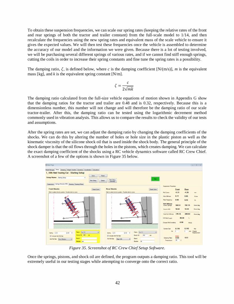
42
To obtain these suspension frequencies, we can scale our spring rates (keeping the relative rates of the front
and rear springs of both the tractor and trailer constant) from the full-scale model to 1/14, and then
recalculate the frequencies using the new spring rates and equivalent mass of the scale vehicle to ensure it
gives the expected values. We will then test these frequencies once the vehicle is assembled to determine
the accuracy of our model and the information we were given. Because there is a lot of testing involved,
we will be purchasing several different springs of various rates, and if we cannot find stiff enough springs,
cutting the coils in order to increase their spring constants and fine tune the spring rates is a possibility.
The damping ratio, 𝜁, is defined below, where c is the damping coefficient [N/(m/s)], m is the equivalent
mass [kg], and k is the equivalent spring constant [N/m].
𝜁 =𝑐
2√𝑚𝑘
The damping ratio calculated from the full-size vehicle equations of motion shown in Appendix G show
that the damping ratios for the tractor and trailer are 0.48 and is 0.32, respectively. Because this is a
dimensionless number, this number will not change and will therefore be the damping ratio of our scale
tractor-trailer. After this, the damping ratio can be tested using the logarithmic decrement method
commonly used in vibration analysis. This allows us to compare the results to check the validity of our tests
and assumptions.
After the spring rates are set, we can adjust the damping ratio by changing the damping coefficients of the
shocks. We can do this by altering the number of holes or hole size in the plastic piston as well as the
kinematic viscosity of the silicone shock oil that is used inside the shock body. The general principle of the
shock damper is that the oil flows through the holes in the pistons, which creates damping. We can calculate
the exact damping coefficient of the shocks using a RC vehicle dynamics software called RC Crew Chief.
A screenshot of a few of the options is shown in Figure 35 below.
Figure 35. Screenshot of RC Crew Chief Setup Software.
Once the springs, pistons, and shock oil are defined, the program outputs a damping ratio. This tool will be
extremely useful in our testing stages while attempting to converge onto the correct ratio.
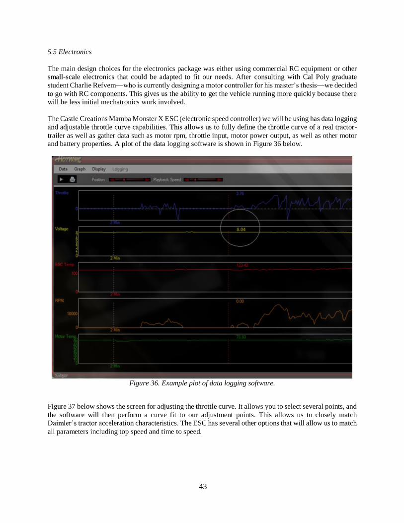
43
5.5 Electronics
The main design choices for the electronics package was either using commercial RC equipment or other
small-scale electronics that could be adapted to fit our needs. After consulting with Cal Poly graduate
student Charlie Refvem—who is currently designing a motor controller for his master’s thesis—we decided
to go with RC components. This gives us the ability to get the vehicle running more quickly because there
will be less initial mechatronics work involved.
The Castle Creations Mamba Monster X ESC (electronic speed controller) we will be using has data logging
and adjustable throttle curve capabilities. This allows us to fully define the throttle curve of a real tractor-
trailer as well as gather data such as motor rpm, throttle input, motor power output, as well as other motor
and battery properties. A plot of the data logging software is shown in Figure 36 below.
Figure 36. Example plot of data logging software.
Figure 37 below shows the screen for adjusting the throttle curve. It allows you to select several points, and
the software will then perform a curve fit to our adjustment points. This allows us to closely match
Daimler’s tractor acceleration characteristics. The ESC has several other options that will allow us to match
all parameters including top speed and time to speed.
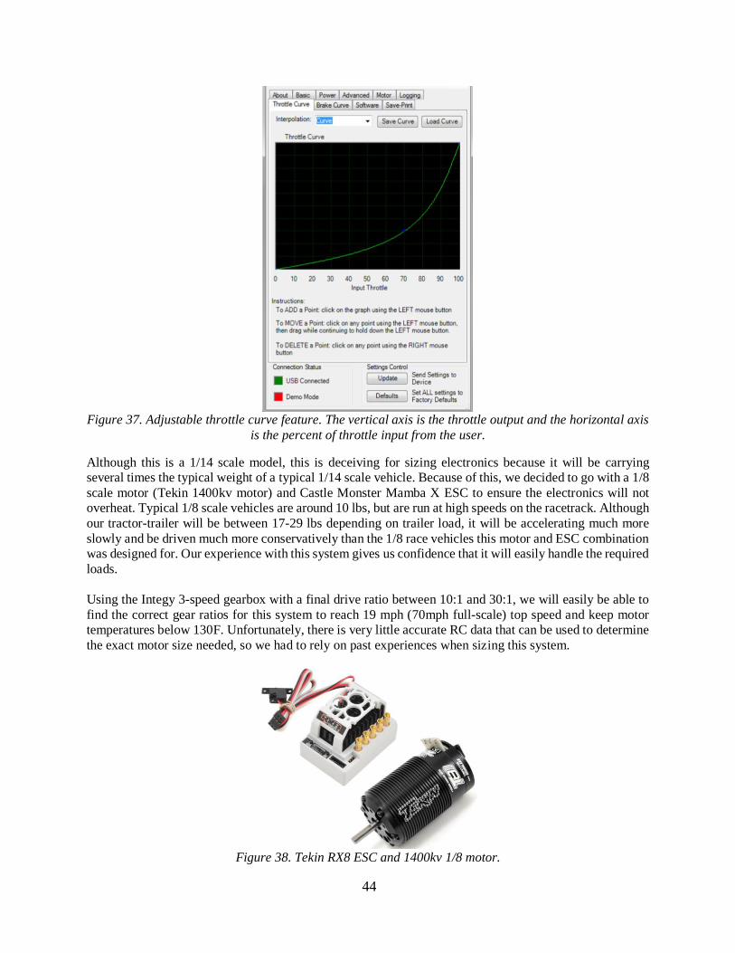
44
Figure 37. Adjustable throttle curve feature. The vertical axis is the throttle output and the horizontal axis
is the percent of throttle input from the user.
Although this is a 1/14 scale model, this is deceiving for sizing electronics because it will be carrying
several times the typical weight of a typical 1/14 scale vehicle. Because of this, we decided to go with a 1/8
scale motor (Tekin 1400kv motor) and Castle Monster Mamba X ESC to ensure the electronics will not
overheat. Typical 1/8 scale vehicles are around 10 lbs, but are run at high speeds on the racetrack. Although
our tractor-trailer will be between 17-29 lbs depending on trailer load, it will be accelerating much more
slowly and be driven much more conservatively than the 1/8 race vehicles this motor and ESC combination
was designed for. Our experience with this system gives us confidence that it will easily handle the required
loads.
Using the Integy 3-speed gearbox with a final drive ratio between 10:1 and 30:1, we will easily be able to
find the correct gear ratios for this system to reach 19 mph (70mph full-scale) top speed and keep motor
temperatures below 130F. Unfortunately, there is very little accurate RC data that can be used to determine
the exact motor size needed, so we had to rely on past experiences when sizing this system.
Figure 38. Tekin RX8 ESC and 1400kv 1/8 motor.
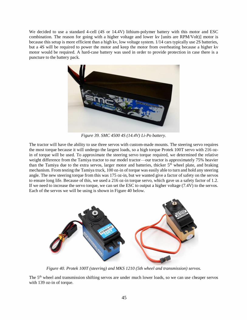
45
We decided to use a standard 4-cell (4S or 14.4V) lithium-polymer battery with this motor and ESC
combination. The reason for going with a higher voltage and lower kv [units are RPM/Volt)] motor is
because this setup is more efficient than a high kv, low voltage system. 1/14 cars typically use 2S batteries,
but a 4S will be required to power the motor and keep the motor from overheating because a higher kv
motor would be required. A hard-case battery was used in order to provide protection in case there is a
puncture to the battery pack.
Figure 39. SMC 4500 4S (14.4V) Li-Po battery.
The tractor will have the ability to use three servos with custom-made mounts. The steering servo requires
the most torque because it will undergo the largest loads, so a high torque Protek 100T servo with 216 oz-
in of torque will be used. To approximate the steering servo torque required, we determined the relative
weight difference from the Tamiya tractor to our model tractor—our tractor is approximately 75% heavier
than the Tamiya due to the extra servos, larger motor and batteries, thicker 5th wheel plate, and braking
mechanism. From testing the Tamiya truck, 100 oz-in of torque was easily able to turn and hold any steering
angle. The new steering torque from this was 175 oz-in, but we wanted give a factor of safety on the servos
to ensure long life. Because of this, we used a 216 oz-in torque servo, which gave us a safety factor of 1.2.
If we need to increase the servo torque, we can set the ESC to output a higher voltage (7.4V) to the servos.
Each of the servos we will be using is shown in Figure 40 below.
Figure 40. Protek 100T (steering) and MKS 1210 (5th wheel and transmission) servos.
The 5th wheel and transmission shifting servos are under much lower loads, so we can use cheaper servos
with 139 oz-in of torque.
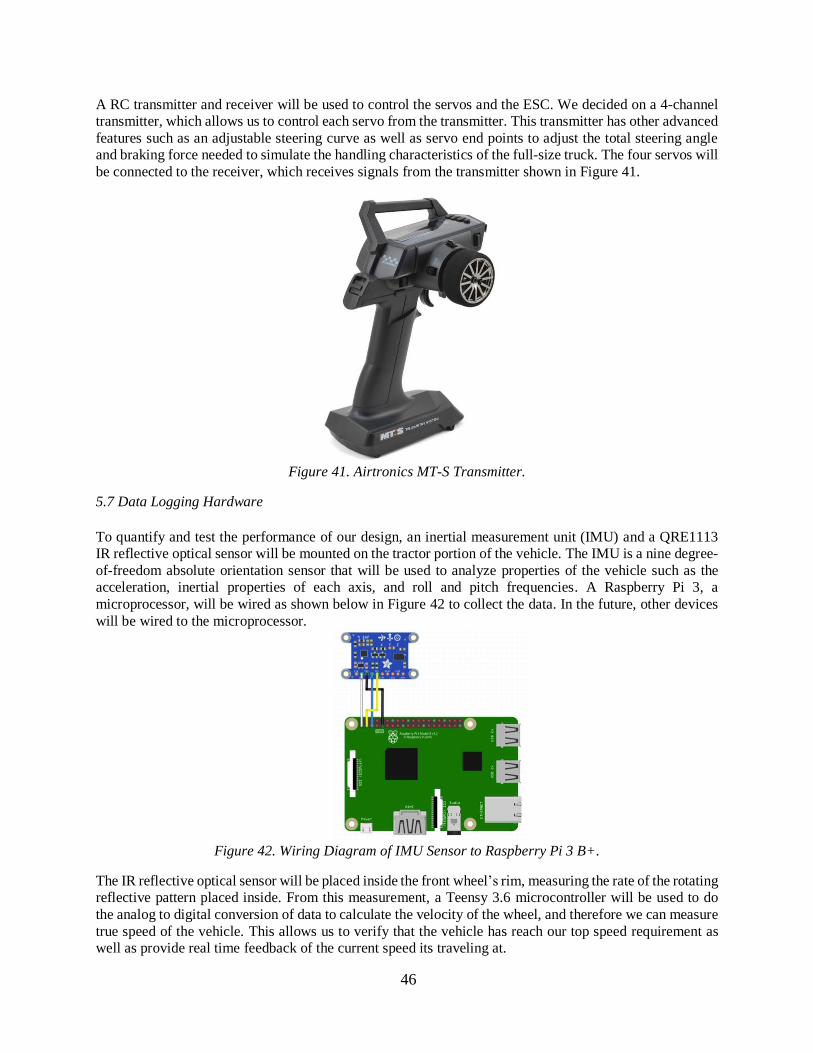
46
A RC transmitter and receiver will be used to control the servos and the ESC. We decided on a 4-channel
transmitter, which allows us to control each servo from the transmitter. This transmitter has other advanced
features such as an adjustable steering curve as well as servo end points to adjust the total steering angle
and braking force needed to simulate the handling characteristics of the full-size truck. The four servos will
be connected to the receiver, which receives signals from the transmitter shown in Figure 41.
Figure 41. Airtronics MT-S Transmitter.
5.7 Data Logging Hardware
To quantify and test the performance of our design, an inertial measurement unit (IMU) and a QRE1113
IR reflective optical sensor will be mounted on the tractor portion of the vehicle. The IMU is a nine degree-
of-freedom absolute orientation sensor that will be used to analyze properties of the vehicle such as the
acceleration, inertial properties of each axis, and roll and pitch frequencies. A Raspberry Pi 3, a
microprocessor, will be wired as shown below in Figure 42 to collect the data. In the future, other devices
will be wired to the microprocessor.
Figure 42. Wiring Diagram of IMU Sensor to Raspberry Pi 3 B+.
The IR reflective optical sensor will be placed inside the front wheel’s rim, measuring the rate of the rotating
reflective pattern placed inside. From this measurement, a Teensy 3.6 microcontroller will be used to do
the analog to digital conversion of data to calculate the velocity of the wheel, and therefore we can measure
true speed of the vehicle. This allows us to verify that the vehicle has reach our top speed requirement as
well as provide real time feedback of the current speed its traveling at.
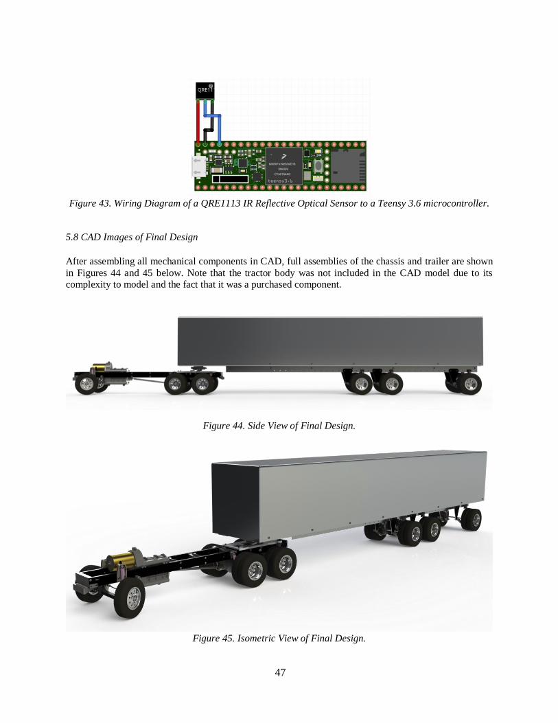
47
Figure 43. Wiring Diagram of a QRE1113 IR Reflective Optical Sensor to a Teensy 3.6 microcontroller.
5.8 CAD Images of Final Design
After assembling all mechanical components in CAD, full assemblies of the chassis and trailer are shown
in Figures 44 and 45 below. Note that the tractor body was not included in the CAD model due to its
complexity to model and the fact that it was a purchased component.
Figure 44. Side View of Final Design.
Figure 45. Isometric View of Final Design.
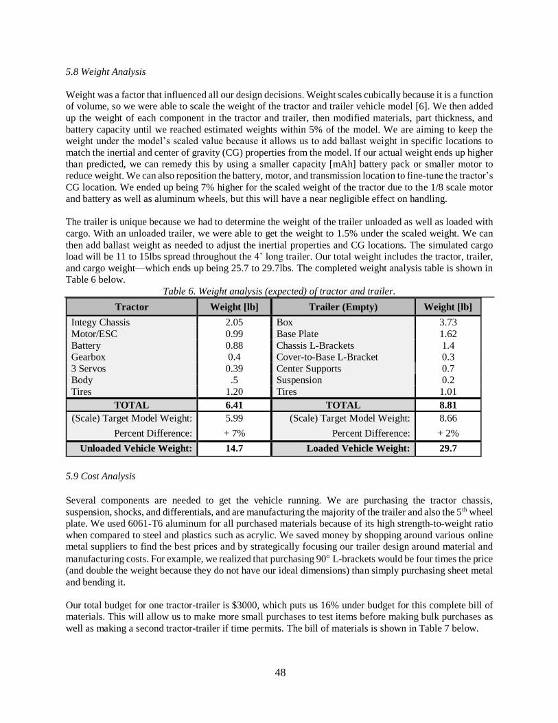
48
5.8 Weight Analysis
Weight was a factor that influenced all our design decisions. Weight scales cubically because it is a function
of volume, so we were able to scale the weight of the tractor and trailer vehicle model [6]. We then added
up the weight of each component in the tractor and trailer, then modified materials, part thickness, and
battery capacity until we reached estimated weights within 5% of the model. We are aiming to keep the
weight under the model’s scaled value because it allows us to add ballast weight in specific locations to
match the inertial and center of gravity (CG) properties from the model. If our actual weight ends up higher
than predicted, we can remedy this by using a smaller capacity [mAh] battery pack or smaller motor to
reduce weight. We can also reposition the battery, motor, and transmission location to fine-tune the tractor’s
CG location. We ended up being 7% higher for the scaled weight of the tractor due to the 1/8 scale motor
and battery as well as aluminum wheels, but this will have a near negligible effect on handling.
The trailer is unique because we had to determine the weight of the trailer unloaded as well as loaded with
cargo. With an unloaded trailer, we were able to get the weight to 1.5% under the scaled weight. We can
then add ballast weight as needed to adjust the inertial properties and CG locations. The simulated cargo
load will be 11 to 15lbs spread throughout the 4’ long trailer. Our total weight includes the tractor, trailer,
and cargo weight—which ends up being 25.7 to 29.7lbs. The completed weight analysis table is shown in
Table 6 below.
Table 6. Weight analysis (expected) of tractor and trailer.
Tractor Weight [lb] Trailer (Empty) Weight [lb]
Integy Chassis 2.05 Box 3.73
Motor/ESC 0.99 Base Plate 1.62
Battery 0.88 Chassis L-Brackets 1.4
Gearbox 0.4 Cover-to-Base L-Bracket 0.3
3 Servos 0.39 Center Supports 0.7
Body .5 Suspension 0.2
Tires 1.20 Tires 1.01
TOTAL 6.41 TOTAL 8.81
(Scale) Target Model Weight: 5.99 (Scale) Target Model Weight: 8.66
Percent Difference: + 7% Percent Difference: + 2%
Unloaded Vehicle Weight: 14.7 Loaded Vehicle Weight: 29.7
5.9 Cost Analysis
Several components are needed to get the vehicle running. We are purchasing the tractor chassis,
suspension, shocks, and differentials, and are manufacturing the majority of the trailer and also the 5th wheel
plate. We used 6061-T6 aluminum for all purchased materials because of its high strength-to-weight ratio
when compared to steel and plastics such as acrylic. We saved money by shopping around various online
metal suppliers to find the best prices and by strategically focusing our trailer design around material and
manufacturing costs. For example, we realized that purchasing 90 L-brackets would be four times the price
(and double the weight because they do not have our ideal dimensions) than simply purchasing sheet metal
and bending it.
Our total budget for one tractor-trailer is $3000, which puts us 16% under budget for this complete bill of
materials. This will allow us to make more small purchases to test items before making bulk purchases as
well as making a second tractor-trailer if time permits. The bill of materials is shown in Table 7 below.
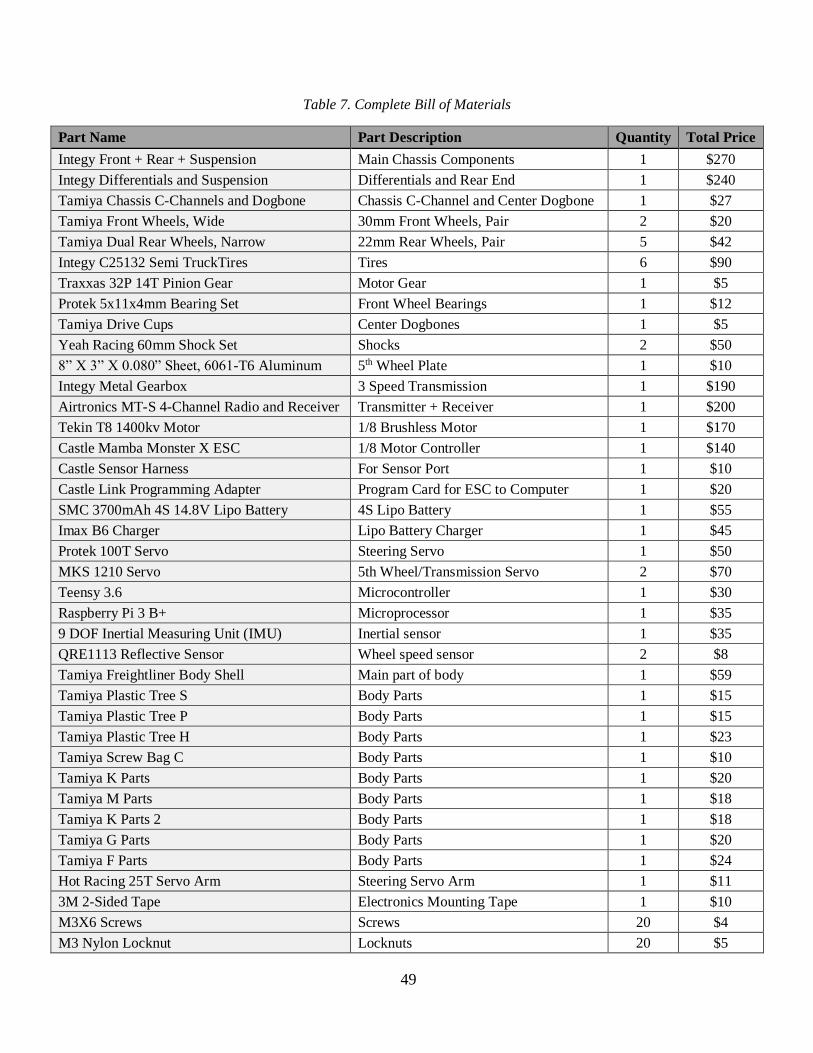
49
Table 7. Complete Bill of Materials
Part Name Part Description Quantity Total Price
Integy Front + Rear + Suspension Main Chassis Components 1 $270
Integy Differentials and Suspension Differentials and Rear End 1 $240
Tamiya Chassis C-Channels and Dogbone Chassis C-Channel and Center Dogbone 1 $27
Tamiya Front Wheels, Wide 30mm Front Wheels, Pair 2 $20
Tamiya Dual Rear Wheels, Narrow 22mm Rear Wheels, Pair 5 $42
Integy C25132 Semi TruckTires Tires 6 $90
Traxxas 32P 14T Pinion Gear Motor Gear 1 $5
Protek 5x11x4mm Bearing Set Front Wheel Bearings 1 $12
Tamiya Drive Cups Center Dogbones 1 $5
Yeah Racing 60mm Shock Set Shocks 2 $50
8” X 3” X 0.080” Sheet, 6061-T6 Aluminum 5th Wheel Plate 1 $10
Integy Metal Gearbox 3 Speed Transmission 1 $190
Airtronics MT-S 4-Channel Radio and Receiver Transmitter + Receiver 1 $200
Tekin T8 1400kv Motor 1/8 Brushless Motor 1 $170
Castle Mamba Monster X ESC 1/8 Motor Controller 1 $140
Castle Sensor Harness For Sensor Port 1 $10
Castle Link Programming Adapter Program Card for ESC to Computer 1 $20
SMC 3700mAh 4S 14.8V Lipo Battery 4S Lipo Battery 1 $55
Imax B6 Charger Lipo Battery Charger 1 $45
Protek 100T Servo Steering Servo 1 $50
MKS 1210 Servo 5th Wheel/Transmission Servo 2 $70
Teensy 3.6 Microcontroller 1 $30
Raspberry Pi 3 B+ Microprocessor 1 $35
9 DOF Inertial Measuring Unit (IMU) Inertial sensor 1 $35
QRE1113 Reflective Sensor Wheel speed sensor 2 $8
Tamiya Freightliner Body Shell Main part of body 1 $59
Tamiya Plastic Tree S Body Parts 1 $15
Tamiya Plastic Tree P Body Parts 1 $15
Tamiya Plastic Tree H Body Parts 1 $23
Tamiya Screw Bag C Body Parts 1 $10
Tamiya K Parts Body Parts 1 $20
Tamiya M Parts Body Parts 1 $18
Tamiya K Parts 2 Body Parts 1 $18
Tamiya G Parts Body Parts 1 $20
Tamiya F Parts Body Parts 1 $24
Hot Racing 25T Servo Arm Steering Servo Arm 1 $11
3M 2-Sided Tape Electronics Mounting Tape 1 $10
M3X6 Screws Screws 20 $4
M3 Nylon Locknut Locknuts 20 $5
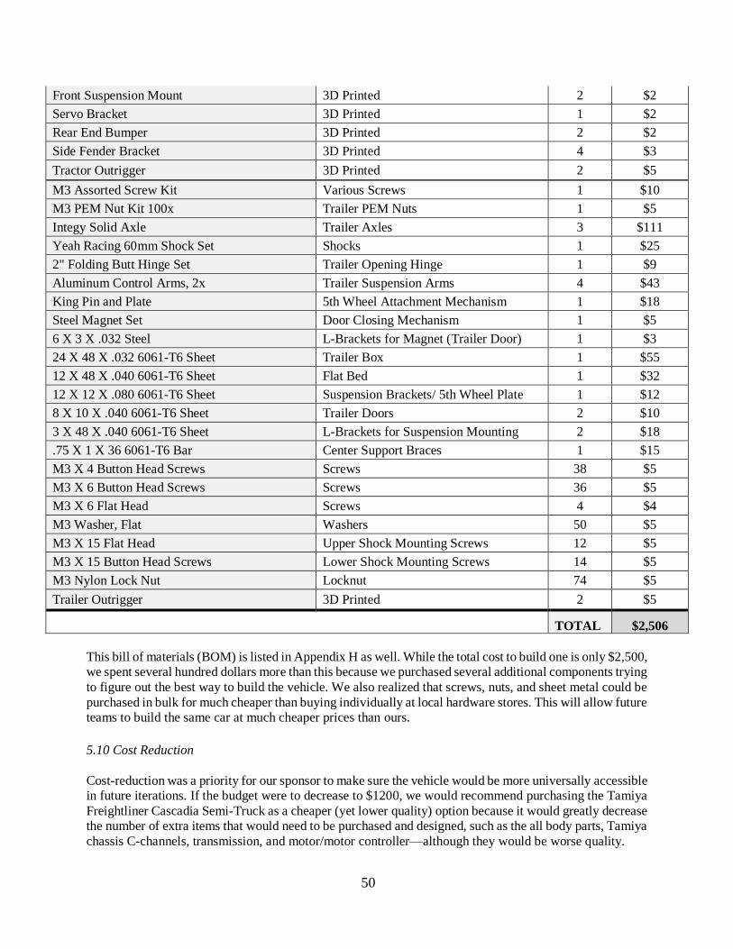
50
Front Suspension Mount 3D Printed 2 $2
Servo Bracket 3D Printed 1 $2
Rear End Bumper 3D Printed 2 $2
Side Fender Bracket 3D Printed 4 $3
Tractor Outrigger 3D Printed 2 $5
M3 Assorted Screw Kit Various Screws 1 $10
M3 PEM Nut Kit 100x Trailer PEM Nuts 1 $5
Integy Solid Axle Trailer Axles 3 $111
Yeah Racing 60mm Shock Set Shocks 1 $25
2" Folding Butt Hinge Set Trailer Opening Hinge 1 $9
Aluminum Control Arms, 2x Trailer Suspension Arms 4 $43
King Pin and Plate 5th Wheel Attachment Mechanism 1 $18
Steel Magnet Set Door Closing Mechanism 1 $5
6 X 3 X .032 Steel L-Brackets for Magnet (Trailer Door) 1 $3
24 X 48 X .032 6061-T6 Sheet Trailer Box 1 $55
12 X 48 X .040 6061-T6 Sheet Flat Bed 1 $32
12 X 12 X .080 6061-T6 Sheet Suspension Brackets/ 5th Wheel Plate 1 $12
8 X 10 X .040 6061-T6 Sheet Trailer Doors 2 $10
3 X 48 X .040 6061-T6 Sheet L-Brackets for Suspension Mounting 2 $18
.75 X 1 X 36 6061-T6 Bar Center Support Braces 1 $15
M3 X 4 Button Head Screws Screws 38 $5
M3 X 6 Button Head Screws Screws 36 $5
M3 X 6 Flat Head Screws 4 $4
M3 Washer, Flat Washers 50 $5
M3 X 15 Flat Head Upper Shock Mounting Screws 12 $5
M3 X 15 Button Head Screws Lower Shock Mounting Screws 14 $5
M3 Nylon Lock Nut Locknut 74 $5
Trailer Outrigger 3D Printed 2 $5
TOTAL $2,506
This bill of materials (BOM) is listed in Appendix H as well. While the total cost to build one is only $2,500,
we spent several hundred dollars more than this because we purchased several additional components trying
to figure out the best way to build the vehicle. We also realized that screws, nuts, and sheet metal could be
purchased in bulk for much cheaper than buying individually at local hardware stores. This will allow future
teams to build the same car at much cheaper prices than ours.
5.10 Cost Reduction
Cost-reduction was a priority for our sponsor to make sure the vehicle would be more universally accessible
in future iterations. If the budget were to decrease to $1200, we would recommend purchasing the Tamiya
Freightliner Cascadia Semi-Truck as a cheaper (yet lower quality) option because it would greatly decrease the number of extra items that would need to be purchased and designed, such as the all body parts, Tamiya
chassis C-channels, transmission, and motor/motor controller—although they would be worse quality.
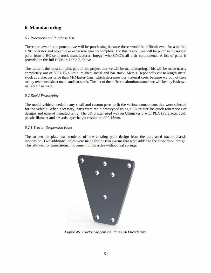
51
6. Manufacturing
6.1 Procurement / Purchase List
There are several components we will be purchasing because these would be difficult even for a skilled
CNC operator and would take excessive time to complete. For this reason, we will be purchasing several
parts from a RC semi-truck manufacturer, Integy, who CNC’s all their components. A list of parts is
provided in the full BOM in Table 7, above.
The trailer is the most complex part of this project that we will be manufacturing. This will be made nearly
completely out of 6061-T6 aluminum sheet metal and bar stock. Metals Depot sells cut-to-length metal
stock at a cheaper price than McMaster-Carr, which decreases our material costs because we do not have
to buy oversized sheet metal and bar stock. The list of the different aluminum stock we will be buy is shown
in Table 7 as well.
6.2 Rapid Prototyping
The model vehicle needed many small and custom parts to fit the various components that were selected
for the vehicle. When necessary, parts were rapid prototyped using a 3D printer for quick reiterations of
designs and ease of manufacturing. The 3D printer used was an Ultimaker 3 with PLA (Polylactic acid)
plastic filament and a z-axis layer height resolution of 0.15mm.
6.2.1 Tractor Suspension Plate
The suspension plate was modeled off the existing plate design from the purchased tractor chassis
suspension. Two additional holes were made for the two a-arms that were added to the suspension design.
This allowed for translational movement of the axles without leaf springs.
Figure 46. Tractor Suspension Plate CAD Rendering.
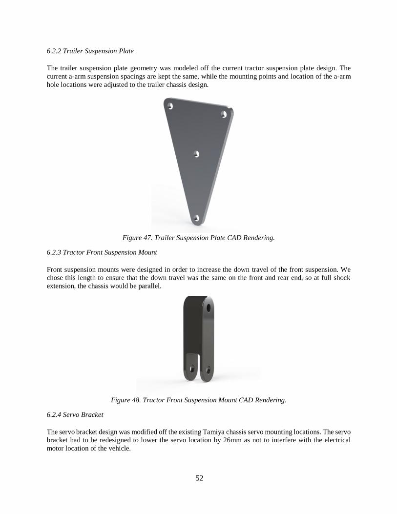
52
6.2.2 Trailer Suspension Plate
The trailer suspension plate geometry was modeled off the current tractor suspension plate design. The
current a-arm suspension spacings are kept the same, while the mounting points and location of the a-arm
hole locations were adjusted to the trailer chassis design.
Figure 47. Trailer Suspension Plate CAD Rendering.
6.2.3 Tractor Front Suspension Mount
Front suspension mounts were designed in order to increase the down travel of the front suspension. We
chose this length to ensure that the down travel was the same on the front and rear end, so at full shock
extension, the chassis would be parallel.
Figure 48. Tractor Front Suspension Mount CAD Rendering.
6.2.4 Servo Bracket
The servo bracket design was modified off the existing Tamiya chassis servo mounting locations. The servo
bracket had to be redesigned to lower the servo location by 26mm as not to interfere with the electrical
motor location of the vehicle.
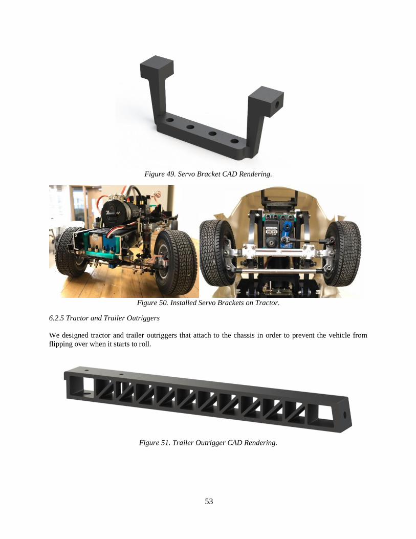
53
Figure 49. Servo Bracket CAD Rendering.
Figure 50. Installed Servo Brackets on Tractor.
6.2.5 Tractor and Trailer Outriggers
We designed tractor and trailer outriggers that attach to the chassis in order to prevent the vehicle from
flipping over when it starts to roll.
Figure 51. Trailer Outrigger CAD Rendering.
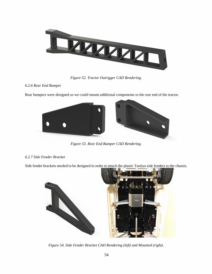
54
Figure 52. Tractor Outrigger CAD Rendering.
6.2.6 Rear End Bumper
Rear bumpers were designed so we could mount additional components to the rear end of the tractor.
Figure 53. Rear End Bumper CAD Rendering.
6.2.7 Side Fender Bracket
Side fender brackets needed to be designed in order to attach the plastic Tamiya side fenders to the chassis.
Figure 54. Side Fender Bracket CAD Rendering (left) and Mounted (right).
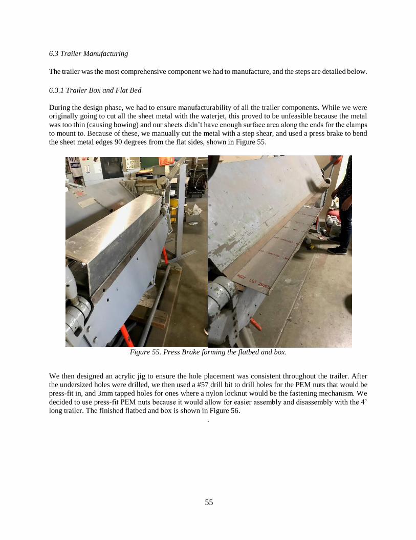
55
6.3 Trailer Manufacturing
The trailer was the most comprehensive component we had to manufacture, and the steps are detailed below.
6.3.1 Trailer Box and Flat Bed
During the design phase, we had to ensure manufacturability of all the trailer components. While we were
originally going to cut all the sheet metal with the waterjet, this proved to be unfeasible because the metal
was too thin (causing bowing) and our sheets didn’t have enough surface area along the ends for the clamps
to mount to. Because of these, we manually cut the metal with a step shear, and used a press brake to bend
the sheet metal edges 90 degrees from the flat sides, shown in Figure 55.
Figure 55. Press Brake forming the flatbed and box.
We then designed an acrylic jig to ensure the hole placement was consistent throughout the trailer. After
the undersized holes were drilled, we then used a #57 drill bit to drill holes for the PEM nuts that would be
press-fit in, and 3mm tapped holes for ones where a nylon locknut would be the fastening mechanism. We
decided to use press-fit PEM nuts because it would allow for easier assembly and disassembly with the 4’
long trailer. The finished flatbed and box is shown in Figure 56.
.
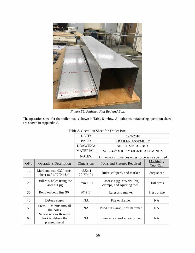
56
Figure 56. Finished Flat Bed and Box.
The operation sheet for the trailer box is shown in Table 8 below. All other manufacturing operation sheets
are shown in Appendix J.
Table 8. Operation Sheet for Trailer Box.
DATE: 12/9/2018 PART: TRAILER ASSEMBLY DRAWING: SHEET METAL BOX MATERIAL: 24” X 48” X 0.032" 6061-T6 ALUMINUM
NOTES: Dimensions in inches unless otherwise specified
OP # Operations Description Dimensions Tools and Fixtures Required Machining
Tool Cell
10 Mark and cut .032" stock
sheet to 21.77”X45.5”
45.5±.1
22.77±.01 Ruler, calipers, and marker Step shear
20 Drill #25 holes using the
laser cut jig 3mm ±0.1
Laser cut jig, #25 drill bit,
clamps, and squaring tool. Drill press
30 Bend on bend line 90⁰ 90⁰± 1⁰ Ruler and marker Press brake
40 Deburr edges NA File or dremel NA
50 Press PEM nuts into all
the holes NA PEM nuts, anvil, soft hammer NA
60
Screw screws through
back to deburr the
pressed metal
NA 3mm screw and screw driver NA
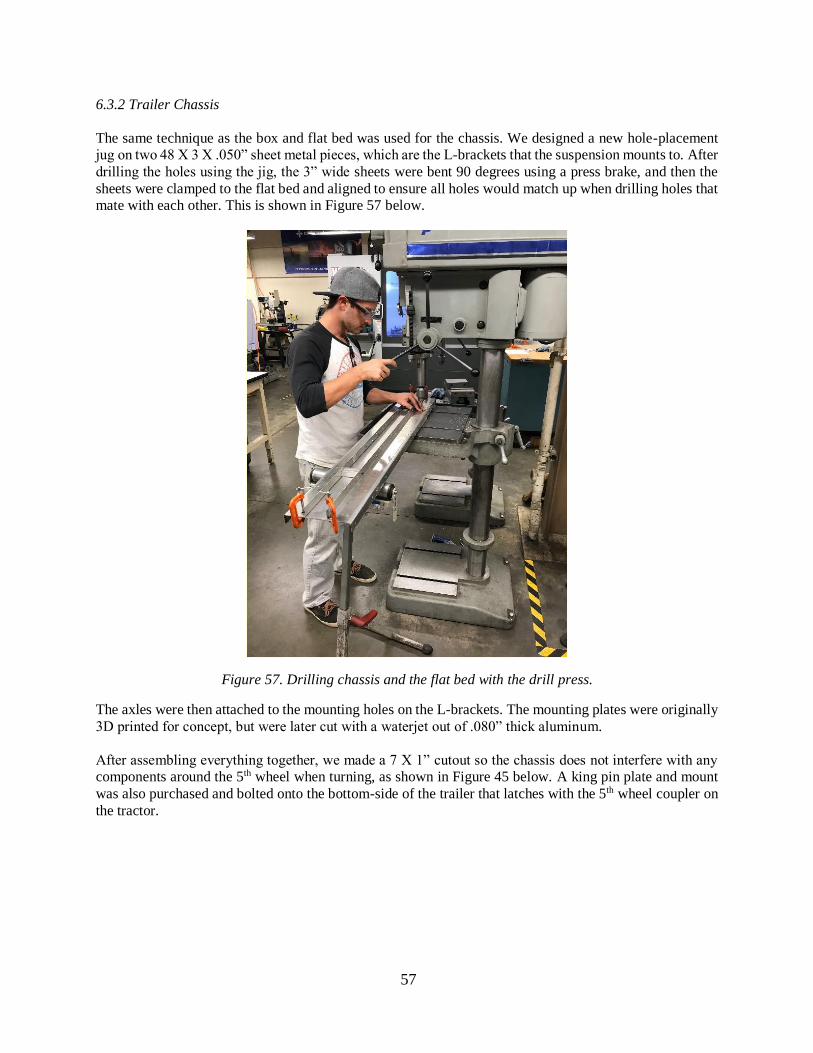
57
6.3.2 Trailer Chassis
The same technique as the box and flat bed was used for the chassis. We designed a new hole-placement
jug on two 48 X 3 X .050” sheet metal pieces, which are the L-brackets that the suspension mounts to. After
drilling the holes using the jig, the 3” wide sheets were bent 90 degrees using a press brake, and then the
sheets were clamped to the flat bed and aligned to ensure all holes would match up when drilling holes that
mate with each other. This is shown in Figure 57 below.
Figure 57. Drilling chassis and the flat bed with the drill press.
The axles were then attached to the mounting holes on the L-brackets. The mounting plates were originally
3D printed for concept, but were later cut with a waterjet out of .080” thick aluminum.
After assembling everything together, we made a 7 X 1” cutout so the chassis does not interfere with any
components around the 5th wheel when turning, as shown in Figure 45 below. A king pin plate and mount
was also purchased and bolted onto the bottom-side of the trailer that latches with the 5th wheel coupler on
the tractor.
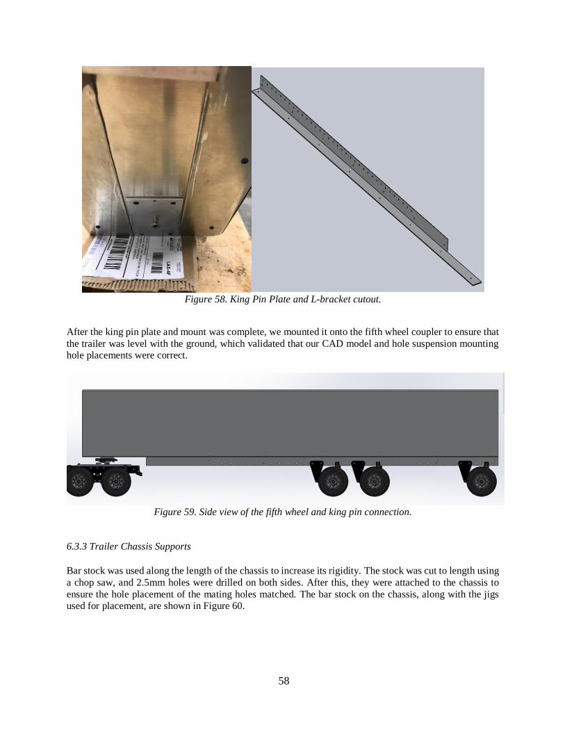
58
Figure 58. King Pin Plate and L-bracket cutout.
After the king pin plate and mount was complete, we mounted it onto the fifth wheel coupler to ensure that
the trailer was level with the ground, which validated that our CAD model and hole suspension mounting
hole placements were correct.
Figure 59. Side view of the fifth wheel and king pin connection.
6.3.3 Trailer Chassis Supports
Bar stock was used along the length of the chassis to increase its rigidity. The stock was cut to length using
a chop saw, and 2.5mm holes were drilled on both sides. After this, they were attached to the chassis to
ensure the hole placement of the mating holes matched. The bar stock on the chassis, along with the jigs
used for placement, are shown in Figure 60.
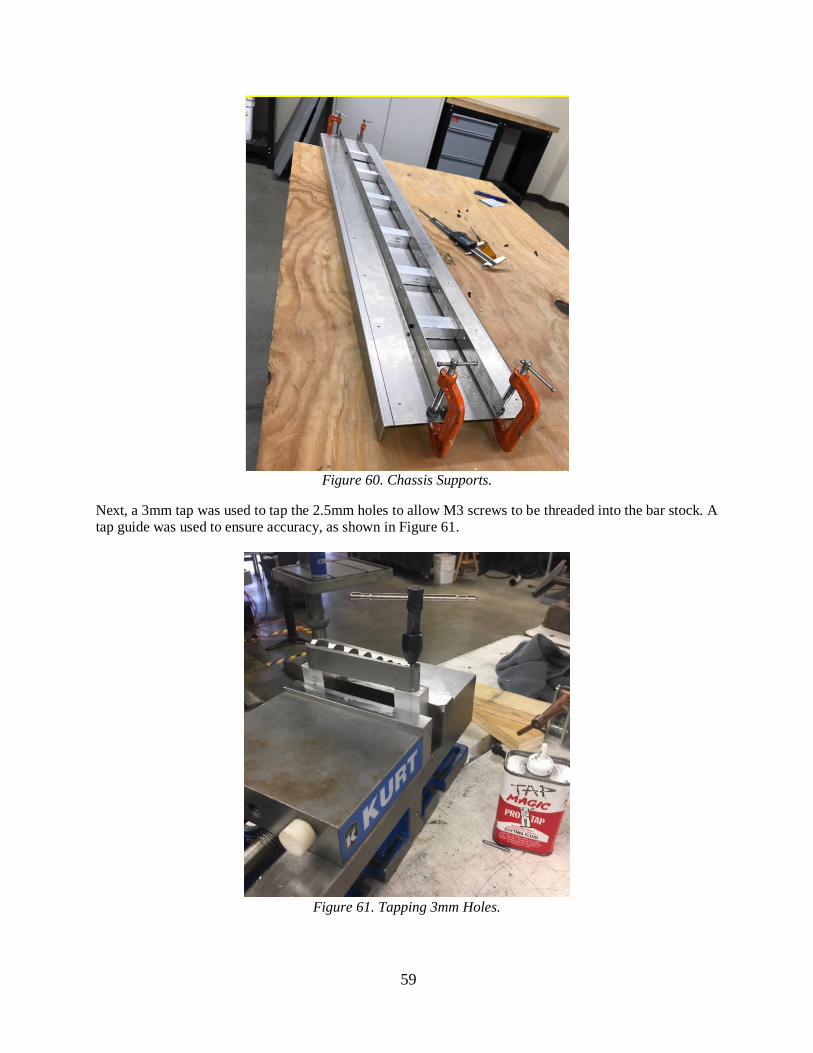
59
Figure 60. Chassis Supports.
Next, a 3mm tap was used to tap the 2.5mm holes to allow M3 screws to be threaded into the bar stock. A
tap guide was used to ensure accuracy, as shown in Figure 61.
Figure 61. Tapping 3mm Holes.
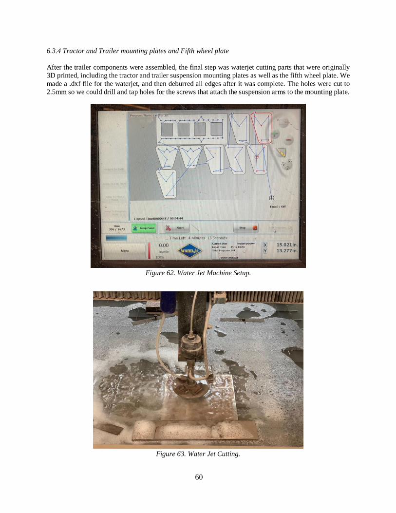
60
6.3.4 Tractor and Trailer mounting plates and Fifth wheel plate
After the trailer components were assembled, the final step was waterjet cutting parts that were originally
3D printed, including the tractor and trailer suspension mounting plates as well as the fifth wheel plate. We
made a .dxf file for the waterjet, and then deburred all edges after it was complete. The holes were cut to
2.5mm so we could drill and tap holes for the screws that attach the suspension arms to the mounting plate.
Figure 62. Water Jet Machine Setup.
Figure 63. Water Jet Cutting.
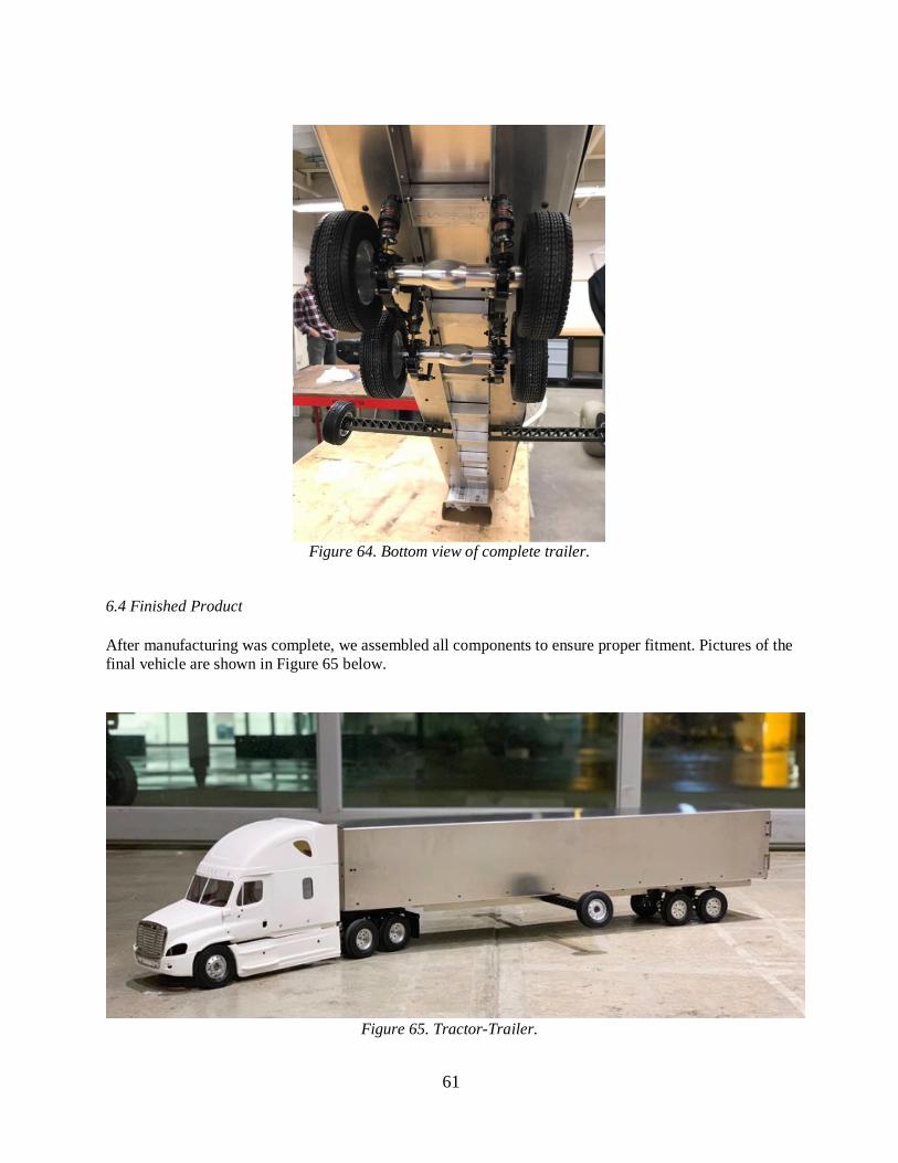
61
Figure 64. Bottom view of complete trailer.
6.4 Finished Product
After manufacturing was complete, we assembled all components to ensure proper fitment. Pictures of the
final vehicle are shown in Figure 65 below.
Figure 65. Tractor-Trailer.
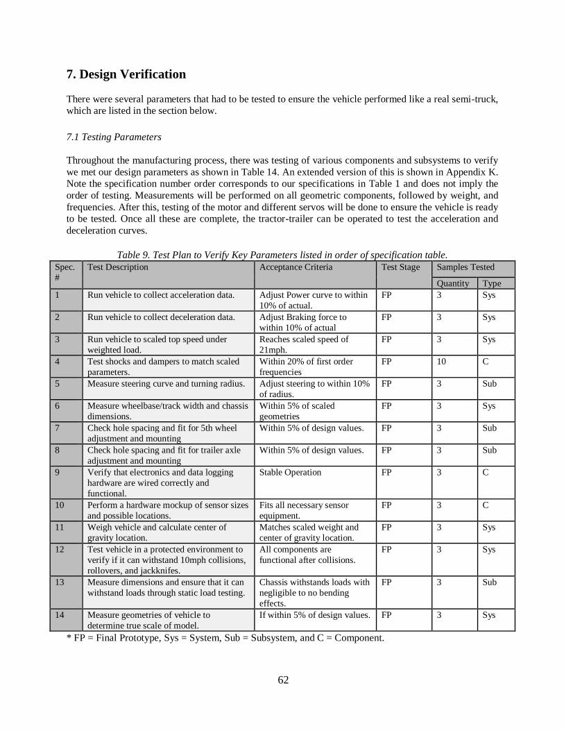
62
7. Design Verification
There were several parameters that had to be tested to ensure the vehicle performed like a real semi-truck,
which are listed in the section below.
7.1 Testing Parameters
Throughout the manufacturing process, there was testing of various components and subsystems to verify
we met our design parameters as shown in Table 14. An extended version of this is shown in Appendix K.
Note the specification number order corresponds to our specifications in Table 1 and does not imply the
order of testing. Measurements will be performed on all geometric components, followed by weight, and
frequencies. After this, testing of the motor and different servos will be done to ensure the vehicle is ready
to be tested. Once all these are complete, the tractor-trailer can be operated to test the acceleration and
deceleration curves.
Table 9. Test Plan to Verify Key Parameters listed in order of specification table.
Spec.
#
Test Description Acceptance Criteria Test Stage Samples Tested
Quantity Type
1 Run vehicle to collect acceleration data. Adjust Power curve to within
10% of actual.
FP 3 Sys
2 Run vehicle to collect deceleration data. Adjust Braking force to
within 10% of actual
FP 3 Sys
3 Run vehicle to scaled top speed under
weighted load.
Reaches scaled speed of
21mph.
FP 3 Sys
4 Test shocks and dampers to match scaled
parameters.
Within 20% of first order
frequencies
FP 10 C
5 Measure steering curve and turning radius. Adjust steering to within 10%
of radius.
FP 3 Sub
6 Measure wheelbase/track width and chassis
dimensions.
Within 5% of scaled
geometries
FP 3 Sys
7 Check hole spacing and fit for 5th wheel
adjustment and mounting
Within 5% of design values. FP 3 Sub
8 Check hole spacing and fit for trailer axle
adjustment and mounting
Within 5% of design values. FP 3 Sub
9 Verify that electronics and data logging
hardware are wired correctly and
functional.
Stable Operation FP 3 C
10 Perform a hardware mockup of sensor sizes
and possible locations.
Fits all necessary sensor
equipment.
FP 3 C
11 Weigh vehicle and calculate center of
gravity location.
Matches scaled weight and
center of gravity location.
FP 3 Sys
12 Test vehicle in a protected environment to
verify if it can withstand 10mph collisions,
rollovers, and jackknifes.
All components are
functional after collisions.
FP 3 Sys
13 Measure dimensions and ensure that it can
withstand loads through static load testing.
Chassis withstands loads with
negligible to no bending
effects.
FP 3 Sub
14 Measure geometries of vehicle to
determine true scale of model.
If within 5% of design values. FP 3 Sys
* FP = Final Prototype, Sys = System, Sub = Subsystem, and C = Component.
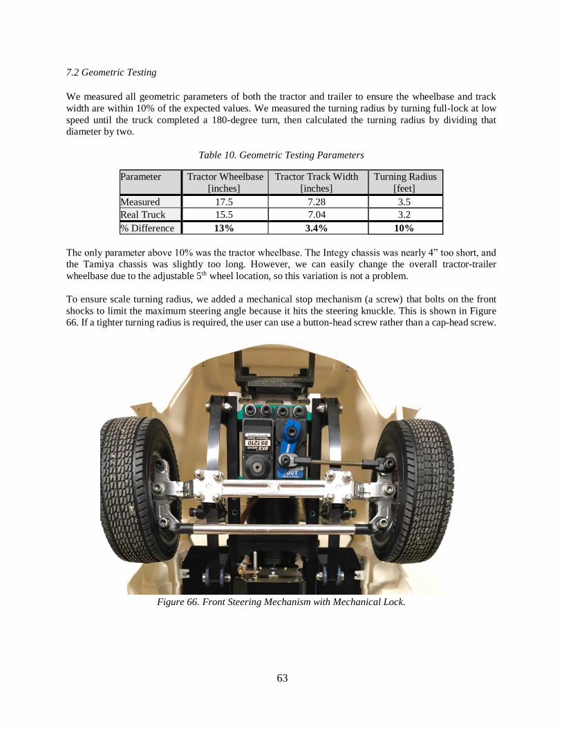
63
7.2 Geometric Testing
We measured all geometric parameters of both the tractor and trailer to ensure the wheelbase and track
width are within 10% of the expected values. We measured the turning radius by turning full-lock at low
speed until the truck completed a 180-degree turn, then calculated the turning radius by dividing that
diameter by two.
Table 10. Geometric Testing Parameters
Parameter Tractor Wheelbase
[inches]
Tractor Track Width
[inches]
Turning Radius
[feet]
Measured 17.5 7.28 3.5
Real Truck 15.5 7.04 3.2
% Difference 13% 3.4% 10%
The only parameter above 10% was the tractor wheelbase. The Integy chassis was nearly 4” too short, and
the Tamiya chassis was slightly too long. However, we can easily change the overall tractor-trailer
wheelbase due to the adjustable 5th wheel location, so this variation is not a problem.
To ensure scale turning radius, we added a mechanical stop mechanism (a screw) that bolts on the front
shocks to limit the maximum steering angle because it hits the steering knuckle. This is shown in Figure
66. If a tighter turning radius is required, the user can use a button-head screw rather than a cap-head screw.
Figure 66. Front Steering Mechanism with Mechanical Lock.
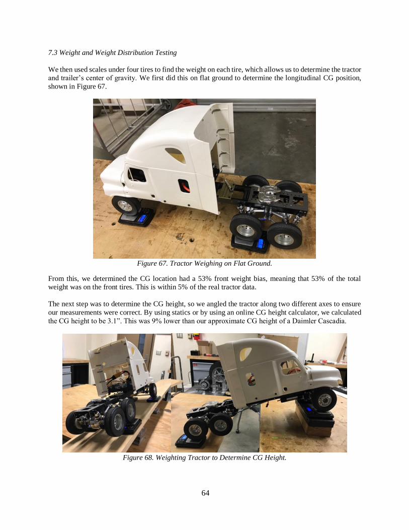
64
7.3 Weight and Weight Distribution Testing
We then used scales under four tires to find the weight on each tire, which allows us to determine the tractor
and trailer’s center of gravity. We first did this on flat ground to determine the longitudinal CG position,
shown in Figure 67.
Figure 67. Tractor Weighing on Flat Ground.
From this, we determined the CG location had a 53% front weight bias, meaning that 53% of the total
weight was on the front tires. This is within 5% of the real tractor data.
The next step was to determine the CG height, so we angled the tractor along two different axes to ensure
our measurements were correct. By using statics or by using an online CG height calculator, we calculated
the CG height to be 3.1”. This was 9% lower than our approximate CG height of a Daimler Cascadia.
Figure 68. Weighting Tractor to Determine CG Height.
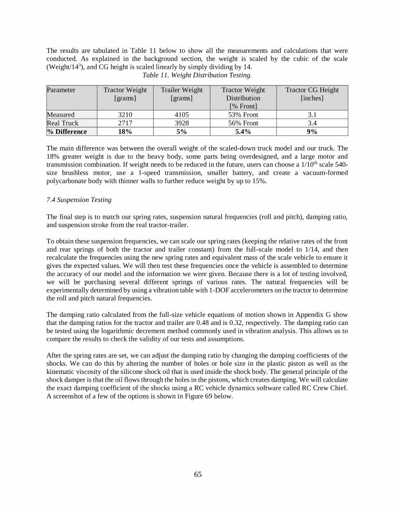
65
The results are tabulated in Table 11 below to show all the measurements and calculations that were
conducted. As explained in the background section, the weight is scaled by the cubic of the scale
(Weight/143), and CG height is scaled linearly by simply dividing by 14.
Table 11. Weight Distribution Testing.
Parameter Tractor Weight
[grams]
Trailer Weight
[grams]
Tractor Weight
Distribution
[% Front]
Tractor CG Height
[inches]
Measured 3210 4105 53% Front 3.1
Real Truck 2717 3928 56% Front 3.4
% Difference 18% 5% 5.4% 9%
The main difference was between the overall weight of the scaled-down truck model and our truck. The
18% greater weight is due to the heavy body, some parts being overdesigned, and a large motor and
transmission combination. If weight needs to be reduced in the future, users can choose a 1/10th scale 540-
size brushless motor, use a 1-speed transmission, smaller battery, and create a vacuum-formed
polycarbonate body with thinner walls to further reduce weight by up to 15%.
7.4 Suspension Testing
The final step is to match our spring rates, suspension natural frequencies (roll and pitch), damping ratio,
and suspension stroke from the real tractor-trailer.
To obtain these suspension frequencies, we can scale our spring rates (keeping the relative rates of the front
and rear springs of both the tractor and trailer constant) from the full-scale model to 1/14, and then
recalculate the frequencies using the new spring rates and equivalent mass of the scale vehicle to ensure it
gives the expected values. We will then test these frequencies once the vehicle is assembled to determine
the accuracy of our model and the information we were given. Because there is a lot of testing involved,
we will be purchasing several different springs of various rates. The natural frequencies will be
experimentally determined by using a vibration table with 1-DOF accelerometers on the tractor to determine
the roll and pitch natural frequencies.
The damping ratio calculated from the full-size vehicle equations of motion shown in Appendix G show
that the damping ratios for the tractor and trailer are 0.48 and is 0.32, respectively. The damping ratio can
be tested using the logarithmic decrement method commonly used in vibration analysis. This allows us to
compare the results to check the validity of our tests and assumptions.
After the spring rates are set, we can adjust the damping ratio by changing the damping coefficients of the
shocks. We can do this by altering the number of holes or hole size in the plastic piston as well as the
kinematic viscosity of the silicone shock oil that is used inside the shock body. The general principle of the shock damper is that the oil flows through the holes in the pistons, which creates damping. We will calculate
the exact damping coefficient of the shocks using a RC vehicle dynamics software called RC Crew Chief.
A screenshot of a few of the options is shown in Figure 69 below.
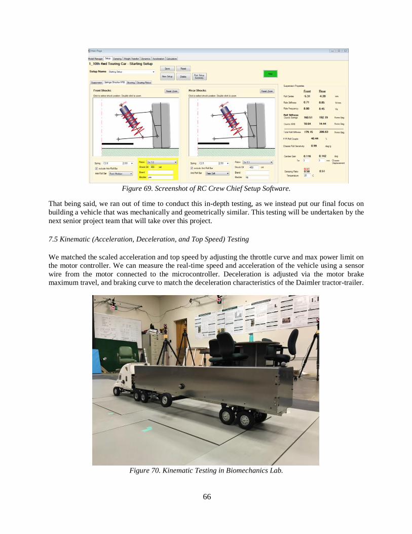
66
Figure 69. Screenshot of RC Crew Chief Setup Software.
That being said, we ran out of time to conduct this in-depth testing, as we instead put our final focus on
building a vehicle that was mechanically and geometrically similar. This testing will be undertaken by the
next senior project team that will take over this project.
7.5 Kinematic (Acceleration, Deceleration, and Top Speed) Testing
We matched the scaled acceleration and top speed by adjusting the throttle curve and max power limit on
the motor controller. We can measure the real-time speed and acceleration of the vehicle using a sensor
wire from the motor connected to the microcontroller. Deceleration is adjusted via the motor brake
maximum travel, and braking curve to match the deceleration characteristics of the Daimler tractor-trailer.
Figure 70. Kinematic Testing in Biomechanics Lab.
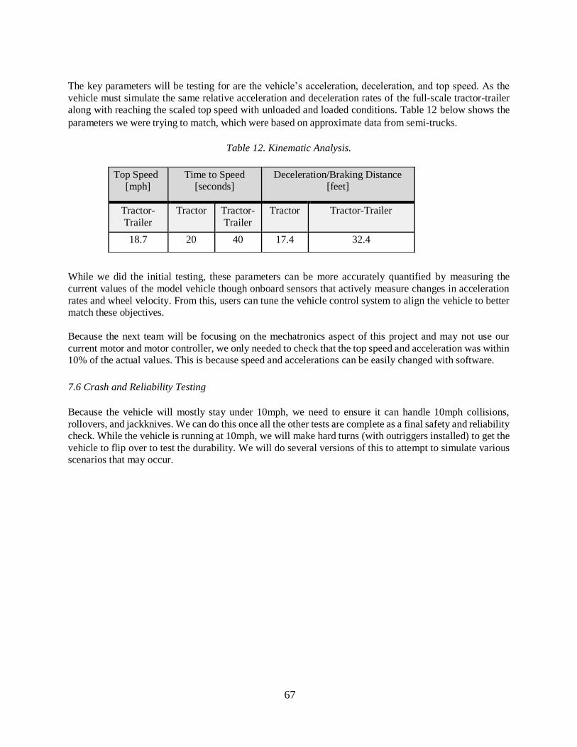
67
The key parameters will be testing for are the vehicle’s acceleration, deceleration, and top speed. As the
vehicle must simulate the same relative acceleration and deceleration rates of the full-scale tractor-trailer
along with reaching the scaled top speed with unloaded and loaded conditions. Table 12 below shows the
parameters we were trying to match, which were based on approximate data from semi-trucks. Kinematic
Analysis. Table 12. Kinematic Analysis.
While we did the initial testing, these parameters can be more accurately quantified by measuring the
current values of the model vehicle though onboard sensors that actively measure changes in acceleration
rates and wheel velocity. From this, users can tune the vehicle control system to align the vehicle to better
match these objectives.
Because the next team will be focusing on the mechatronics aspect of this project and may not use our
current motor and motor controller, we only needed to check that the top speed and acceleration was within
10% of the actual values. This is because speed and accelerations can be easily changed with software.
7.6 Crash and Reliability Testing
Because the vehicle will mostly stay under 10mph, we need to ensure it can handle 10mph collisions,
rollovers, and jackknives. We can do this once all the other tests are complete as a final safety and reliability
check. While the vehicle is running at 10mph, we will make hard turns (with outriggers installed) to get the
vehicle to flip over to test the durability. We will do several versions of this to attempt to simulate various
scenarios that may occur.
Top Speed
[mph]
Time to Speed
[seconds]
Deceleration/Braking Distance
[feet]
Tractor-
Trailer
Tractor Tractor-
Trailer
Tractor Tractor-Trailer
18.7 20 40 17.4 32.4
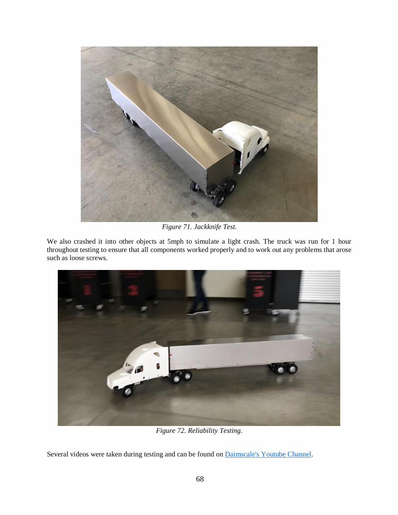
68
Figure 71. Jackknife Test.
We also crashed it into other objects at 5mph to simulate a light crash. The truck was run for 1 hour
throughout testing to ensure that all components worked properly and to work out any problems that arose
such as loose screws.
Figure 72. Reliability Testing.
Several videos were taken during testing and can be found on Daimscale's Youtube Channel.
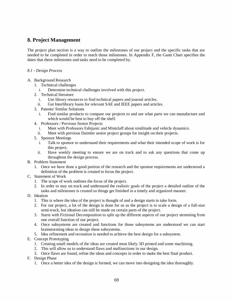
69
8. Project Management
The project plan section is a way to outline the milestones of our project and the specific tasks that are
needed to be completed in order to reach those milestones. In Appendix F, the Gantt Chart specifies the
dates that these milestones and tasks need to be completed by.
8.1 - Design Process
A. Background Research
1. Technical challenges
i. Determine technical challenges involved with this project.
2. Technical literature
i. Use library resources to find technical papers and journal articles. ii. Get Interlibrary loans for relevant SAE and IEEE papers and articles.
3. Patents/ Similar Solutions
i. Find similar products to compare our projects to and see what parts we can manufacture and
which would be best to buy off the shelf.
4. Professors / Previous Senior Projects
i. Meet with Professors Fabijanic and Mintzlaff about similitude and vehicle dynamics.
ii. Meet with previous Daimler senior project groups for insight on their projects.
5. Sponsor Meetings
i. Talk to sponsor to understand their requirements and what their intended scope of work is for
this project.
ii. Have weekly meeting to ensure we are on track and to ask any questions that come up
throughout the design process.
B. Problem Statement
1. Once we have done a good portion of the research and the sponsor requirements are understood a
definition of the problem is created to focus the project.
C. Statement of Work
1. The scope of work outlines the focus of the project.
2. In order to stay on track and understand the realistic goals of the project a detailed outline of the
tasks and milestones is created so things get finished in a timely and organized manner.
D. Ideation
1. This is where the idea of the project is thought of and a design starts to take form.
2. For our project, a lot of the design is done for us as the project is to scale a design of a full-size
semi-truck, but ideation can still be made on certain parts of the project.
3. Starts with Fictional Decomposition to split up the different aspects of our project stemming from
one overall function of our project.
4. Once subsystems are created and functions for those subsystems are understood we can start
brainstorming ideas to design these subsystems.
5. Idea refinement and recreation is needed to achieve the best design for a subsystem.
E. Concept Prototyping
1. Creating small models of the ideas are created most likely 3D printed and some machining.
2. This will allow us to understand flaws and malfunctions in our design.
3. Once flaws are found, refine the ideas and concepts in order to make the best final product.
F. Design Phase
1. Once a better idea of the design is formed, we can move into designing the idea thoroughly.
70
2. Transforming ideas and prototypes into 3D CAD models in SolidWorks would be one of the
methods.
3. This also involves thorough analysis, static calculations, and maybe some FEA.
G. Preliminary Design Review (PDR)
1. This is where a preliminary design is presented to the advisor and the sponsor.
2. The design is critiqued, and better and new ideas are formed.
3. This lets the sponsor know what ideas we are thinking of and lets them tell us if we are on track or
not.
H. Analysis
1. We must determine all the vehicle dynamics parameters needed, and do a Buckingham Pi analysis
to determine the needed scale parameters.
2. Tire testing analysis to determine the cornering stiffness values needed for our model.
3. Vibration analysis in forms such as roll, bounce, and pitch.
4. Some structural analysis is needed to make sure the design can withstand the sponsor’s
requirements of low speed collisions, rollovers, and jackknifes.
5. Static and dynamic analysis of components need to be drawn out with hand calculations and
MATLAB.
I. Intermediate Design Review (IDR)
1. This is an informal update on our design choices and a further in-depth analysis of the designs.
2. We should start thinking of what will be outsourced and how to manufacture in house parts and
what materials to use.
3. Shows what is still needed to be ready for the Critical Design Review.
J. Structural Prototype
1. This is where we take designs from the IDR and create semi functional prototypes to better assess
functionality.
2. A rough overall prototype will be created and a finalized prototype of one subsystem will be made.
K. Critical Design Review (CDR)
1. This is where all design will be finalized.
2. All materials and outsourced parts priced and ready to order.
3. Finalized detail analysis will be presented to our sponsor and approved.
4. A detailed plan of the test and verification process of each design subsystem.
L. Risk Assessment/Safety Review
1. Identify all risks.
2. Plan to manage risks.
M. Status Report
1. Updates project progression.
N. Manufacturing and Test Review
1. Update on test plan and parts that will be manufactured.
2. Schedule project completion and do safety checklist.
O. Operator’s Manual
1. Instructions on the operation of the design.
P. Final Design Review
1. Final report of the completed design.
2. Final prototype.
3. Project Expo Poster.
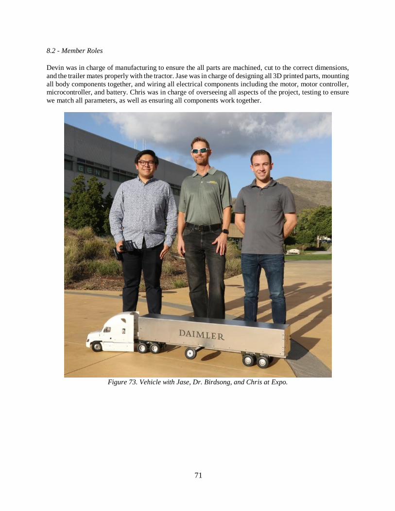
71
8.2 - Member Roles
Devin was in charge of manufacturing to ensure the all parts are machined, cut to the correct dimensions,
and the trailer mates properly with the tractor. Jase was in charge of designing all 3D printed parts, mounting
all body components together, and wiring all electrical components including the motor, motor controller,
microcontroller, and battery. Chris was in charge of overseeing all aspects of the project, testing to ensure
we match all parameters, as well as ensuring all components work together.
Figure 73. Vehicle with Jase, Dr. Birdsong, and Chris at Expo.
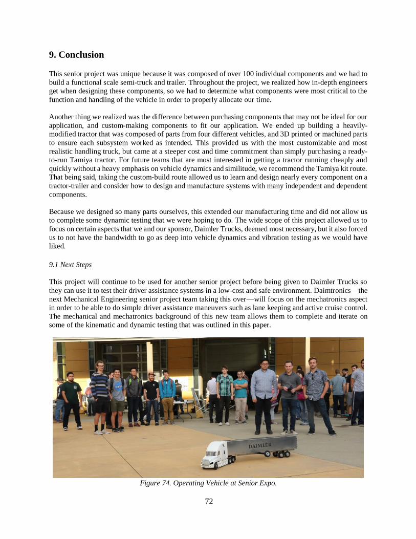
72
9. Conclusion
This senior project was unique because it was composed of over 100 individual components and we had to
build a functional scale semi-truck and trailer. Throughout the project, we realized how in-depth engineers
get when designing these components, so we had to determine what components were most critical to the
function and handling of the vehicle in order to properly allocate our time.
Another thing we realized was the difference between purchasing components that may not be ideal for our
application, and custom-making components to fit our application. We ended up building a heavily-
modified tractor that was composed of parts from four different vehicles, and 3D printed or machined parts
to ensure each subsystem worked as intended. This provided us with the most customizable and most
realistic handling truck, but came at a steeper cost and time commitment than simply purchasing a ready-
to-run Tamiya tractor. For future teams that are most interested in getting a tractor running cheaply and
quickly without a heavy emphasis on vehicle dynamics and similitude, we recommend the Tamiya kit route.
That being said, taking the custom-build route allowed us to learn and design nearly every component on a
tractor-trailer and consider how to design and manufacture systems with many independent and dependent
components.
Because we designed so many parts ourselves, this extended our manufacturing time and did not allow us
to complete some dynamic testing that we were hoping to do. The wide scope of this project allowed us to
focus on certain aspects that we and our sponsor, Daimler Trucks, deemed most necessary, but it also forced
us to not have the bandwidth to go as deep into vehicle dynamics and vibration testing as we would have
liked.
9.1 Next Steps
This project will continue to be used for another senior project before being given to Daimler Trucks so
they can use it to test their driver assistance systems in a low-cost and safe environment. Daimtronics—the
next Mechanical Engineering senior project team taking this over—will focus on the mechatronics aspect
in order to be able to do simple driver assistance maneuvers such as lane keeping and active cruise control.
The mechanical and mechatronics background of this new team allows them to complete and iterate on
some of the kinematic and dynamic testing that was outlined in this paper.
Figure 74. Operating Vehicle at Senior Expo.
73
References [1] Miley, Jay, et al. “Small-Scale Intelligent Vehicle Design Platform.” Digital Commons, Cal Poly
Mechanical Engineering, June 2017, digitalcommons.calpoly.edu/mesp/369/.
[2] “Tamiya America.” Tamiya RC Freighliner Cascadia Evo, Tamiya America,
www.tamiyausa.com/items/radio-control-kits-30/1-14-scale-r-c-tractor-trucks-35000/rc-
freightliner-cascadia-evo--56340.
[3] “Billet Machined Rolling Chassis for Custom 1/14 Semi-Tractor Truck.” Team Integy,
www.integy.com/st_prod.html?p_prodid=22091#.WsLMLJPwaMI.
[4] S. N. Brennan, Modeling and Control Issues Associated with Scaled Vehicles, Masters Thesis, The
University of Illinois, Urbana, IL, 1999.
[5] Williams, Daniel Eugene. "Generalised multi-axle vehicle handling." Vehicle system dynamics 50.1
(2012): 149-166.
[6] Trangsrud, C., Law, E., and Janajreh, I., "Ride Dynamics and Pavement Loading of Tractor Semi-
Trailers on Randomly Rough Roads," SAE Technical Paper 2004-01-2622,
2004, https://doi.org/10.4271/2004-01-2622.
[7] Liburdi, Andrew, "Development of a Scale Vehicle Dynamics Test Bed" (2010). Electronic Theses
and Dissertations. Paper 195
[8] Brennan, Sean N. Modeling and control issues associated with scaled vehicles. MS thesis. University
of Illinois at Urbana-Champaign, 1999.
[9] Milliken, William F., et al. Race Car Vehicle Dynamics. SAE International, 1995.
[10] Luijten, M. F. J., et al. "Analysis of the lateral dynamic behavior of articulated commercial vehicles."
(2011).
[11] Pratt. “Tank and Container Chassis.” Prattinc.com, Pratt Industries Inc, 2018,
prattinc.com/products/tank-and-container-chassis/.
[12] “Carson Trailer axle with air suspension” the Border, https://www.the-border.com/Carson-Trailer-
axle-with-air-suspension-50907069.html
[13] P. Haney, The Racing & High Performance Tire, Society of Automotive Engineers, Warrendale, Pa,
2003.
[14] Hoblet, Phillip, R. T. O'Brien, and Jenelle Armstrong Piepmeier. "Scale-model vehicle analysis for
the design of a steering controller." System Theory, 2003. Proceedings of the 35th Southeastern
Symposium on. IEEE, 2003.
[15] Lalanne, Christian. Mechanical Shock. 3rd ed. 2014. Mechanical Vibrations and Shock Analysis;
Volume 2. Web.
74
Appendices
Appendix A: QFD House of Quality
Appendix B: MATLAB Scaled Speed Calculations
Appendix C: Decision Matrices
Appendix D: Concept Layout Drawings
Appendix E: Hazard Checklist
Appendix F: Gantt Chart
Appendix G: Equations of Motion to Determine Frequencies and Damping Ratio.
Appendix H: Bill of Materials
Appendix I: Drawing Package
Appendix J: Manufacturing Operation Sheets
Appendix K: Operators Manual
Appendix L: Design Verification Plan
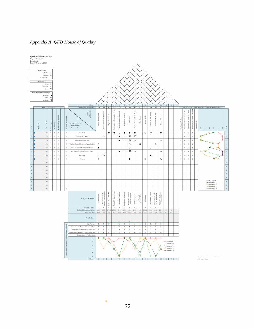
75
QFD: House of QualityProject: DaimScale
Revision: 1
Date: February 1, 2018
HO
W:
En
gin
eeri
ng
Sp
eci
fica
tion
s
WHAT: Customer
Requirements
(explicit & implicit)
1 ||||||||| 19% 9 9 8 9 4 3 3 2 1
2 ||||| 11% 7 5 3 9 5 0 0 0 2
3 ||||| 11% 7 5 3 9 5 0 0 0 3
4 |||||||| 17% 7 8 8 9 4 3 3 4 4
5 ||||||| 15% 6 8 7 9 4 2 2 4 5
6 ||| 7% 5 3 2 9 5 5 1 0 6
7 ||| 7% 3 3 3 9 5 5 4 1 7
8 |||||| 14% 6 7 6 9 3 3 3 4 8
9 0% 9
10 0% 10
11 0% 11
12 0% 12
13 0% 13
14 0% 14
15 0% 15
16 0% 9 16
D
r. B
ird
son
g
F
utu
re C
al
Poly
Stu
den
ts
WHO: Daimler Trucks
Template Revision: 0.9 Date: 4/23/2010
Christopher Battles
Cu
rren
t P
rod
uct
Assesm
en
t -
En
gin
eeri
ng S
peci
fica
tion
s
NOW: Current Product Assesment - Customer Requirements
M
axim
um
Rela
tion
sh
ip
32
10
Competitor #1: Tamiya 1/14 Semi-Truck
Competitor #2: Integy 1/14 Semi-Truck
Competitor #3: Diamler 2017 Senior Project
Competitor #4: Product Name
54
5
5
5
5
Our Product
5 3 5 2
2
2 5 3 0 2 5 2 5
0 5 0 0 3
5
5 4 2 0 5 5
4 4 4 5 5 5
3 1 5 3 0
5
R
ow
#
5
1 2 3 4
O
ur
Cu
rren
t P
rod
uct
C
om
peti
tor
#1
: T
am
iya
1:1
4 R
C
C
om
peti
tor
#2
: In
tegy 1
:14
Mod
el
C
om
peti
tor
#3
: C
al
Poly
Pre
vio
us P
roje
ct
C
om
peti
tor
#4
:
0
9 9
| || | ||||
0%
Correlations
Positive +
Negative −No Correlation
Direction of Improvement
Relationships
Strong ●Moderate ○
Weak ▽
▲
◇
▼
Maximize
Target
Minimize
9 3 99 9 9 9 9 9
◇ ◇4 5 6 7 8 9 10
Technical Importance Rating
HOW MUCH: Target
Max Relationship 9 9
14 15 16Column #
Weight Chart
Relative Weight
5 4 5 5
8 9 10 11 12 131 2 3 4 5 6 7
|||| |||
5 4 2 0 5 5 3
0%
|||||
||| ||| ||||||
|||||
|||||||
9% 6% 4% 5% 2% 10%10% 2% 7% 7% 13% 10% 16%
234.1 152250.5 38.5 170.3 170.3 312 255.3 386.4
10
ft T
urn
ing R
ad
ius
Off
-Th
e-S
helf
Mic
roco
ntr
oll
ers
50
lb
s m
ax
4x2
an
d 6
x2
Ch
assis
Mic
roco
ntr
oll
ers
wit
h
MA
TL
AB
Su
pp
ort
Wit
hin
5%
of
full
-sca
le
tra
ctor-
tra
iler
0 098.333 124.3 50.67 237.3
◇ ◇ ◇14 15 16
◇ ◇ ◇ ◇ ◇Column #
30
cu
bic
in
ches
Wit
hsta
nd
s 1
0m
ph
coll
isio
sn
an
d r
oll
ing o
ver
Sca
led
S
peed
of
70
MP
H
Wit
hin
5 %
of
pow
er
curv
e
Lin
ea
r R
ail
s a
nd
Pin
s
Da
mp
en
ers
an
d S
pri
ngs
Ca
n T
est
in F
ootb
all
Fie
ld T
esti
ng A
rea
1
◇2 3
● ●
◇ ◇
Da
imle
r E
ngin
eers
R
ela
tive W
eig
ht
R
ow
#
W
eig
ht
Ch
art
Direction of Improvement
▽●
●▽
○
● ○ ▽ ○
○
○
○
▽ ●
○● ○ ▽ ○
○ ● ○ ▽ ▽
○ ▽ ●● ○ ●●
○
○
○
Similitude
Adjustable 5th Wheel
Adjustable Trailer Axle
Wireless Manual Control w/Upgradability
Space for Sensor Hardware in Tractor
Two Different Tractor-Trailer Configs
Ste
eri
ng C
urv
e a
nd
Ma
x A
ngle
Inte
rna
l S
tora
ge S
pa
ce
Veh
icle
ca
n w
ith
sta
nd
coll
isio
ns
Top
Vech
icle
Sp
eed
Acc
ele
rati
on
& D
ece
lera
tion
Cu
rves
Ad
justa
ble
Ch
assis
Geom
etr
y
Su
sp
en
sio
n G
eom
etr
y
Veh
icle
Siz
e
○
●
Aesthetics
Portable
Ch
assis
an
d B
od
y D
esig
n
Work
s w
ith
MA
TL
AB
Cen
ter
of
Gra
vit
y
11 12
◇ ◇
Veh
icle
Weig
ht
User
Con
trol
+
+
−
13
Our Product
Competitor #1
Competitor #2
Competitor #3
Competitor #4
Our Product
Competitor #1
Competitor #2
Competitor #3
Competitor #4
Appendix A: QFD House of Quality
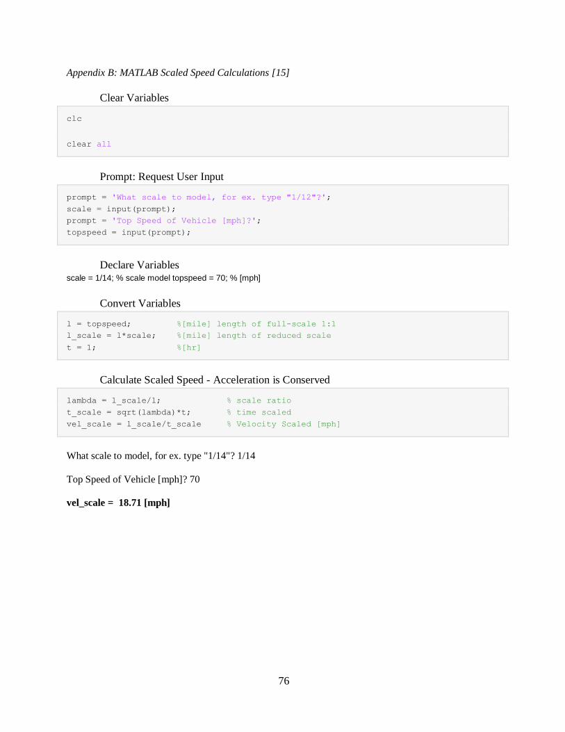
76
Appendix B: MATLAB Scaled Speed Calculations [15]
Clear Variables
clc
clear all
Prompt: Request User Input
prompt = 'What scale to model, for ex. type "1/12"?';
scale = input(prompt);
prompt = 'Top Speed of Vehicle [mph]?';
topspeed = input(prompt);
Declare Variables scale = 1/14; % scale model topspeed = 70; % [mph]
Convert Variables
l = topspeed; %[mile] length of full-scale 1:1
l_scale = l*scale; %[mile] length of reduced scale
t = 1; %[hr]
Calculate Scaled Speed - Acceleration is Conserved
lambda = l_scale/l; % scale ratio
t_scale = sqrt(lambda)*t; % time scaled
vel_scale = l_scale/t_scale % Velocity Scaled [mph]
What scale to model, for ex. type "1/14"? 1/14
Top Speed of Vehicle [mph]? 70
vel_scale = 18.71 [mph]
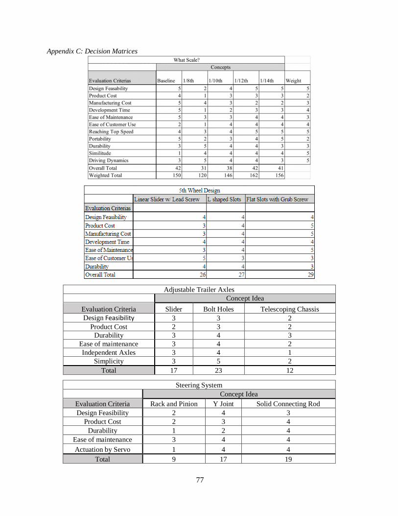
77
Appendix C: Decision Matrices
Adjustable Trailer Axles
Concept Idea
Evaluation Criteria Slider Bolt Holes Telescoping Chassis
Design Feasibility 3 3 2
Product Cost 2 3 2
Durability 3 4 3
Ease of maintenance 3 4 2
Independent Axles 3 4 1
Simplicity 3 5 2
Total 17 23 12
Steering System
Concept Idea
Evaluation Criteria Rack and Pinion Y Joint Solid Connecting Rod
Design Feasibility 2 4 3
Product Cost 2 3 4
Durability 1 2 4
Ease of maintenance 3 4 4
Actuation by Servo 1 4 4
Total 9 17 19
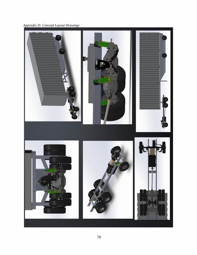
78
Appendix D: Concept Layout Drawings
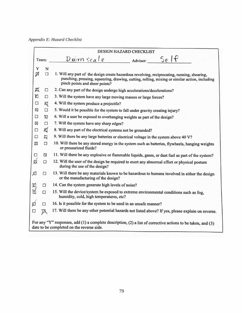
79
Appendix E: Hazard Checklist
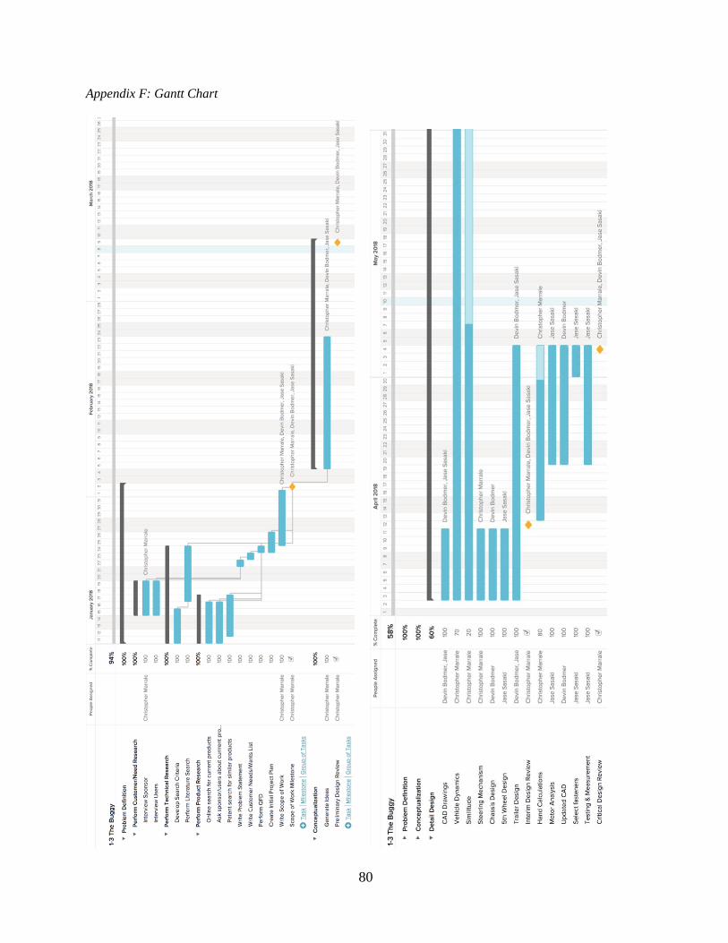
80
Appendix F: Gantt Chart
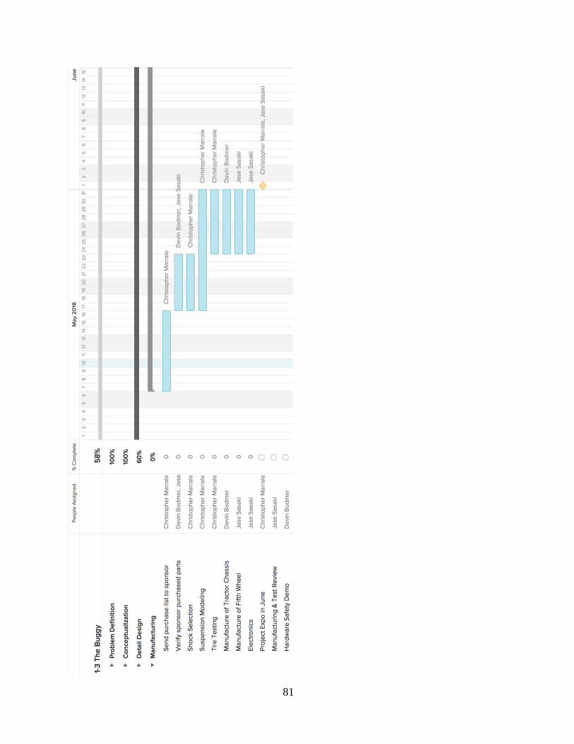
81
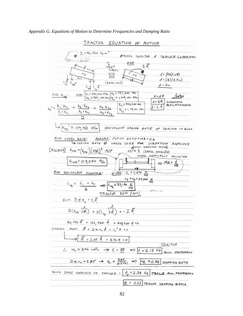
82
Appendix G. Equations of Motion to Determine Frequencies and Damping Ratio
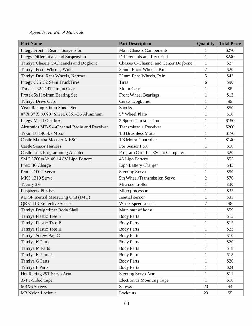
83
Appendix H: Bill of Materials
Part Name Part Description Quantity Total Price
Integy Front + Rear + Suspension Main Chassis Components 1 $270
Integy Differentials and Suspension Differentials and Rear End 1 $240
Tamiya Chassis C-Channels and Dogbone Chassis C-Channel and Center Dogbone 1 $27
Tamiya Front Wheels, Wide 30mm Front Wheels, Pair 2 $20
Tamiya Dual Rear Wheels, Narrow 22mm Rear Wheels, Pair 5 $42
Integy C25132 Semi TruckTires Tires 6 $90
Traxxas 32P 14T Pinion Gear Motor Gear 1 $5
Protek 5x11x4mm Bearing Set Front Wheel Bearings 1 $12
Tamiya Drive Cups Center Dogbones 1 $5
Yeah Racing 60mm Shock Set Shocks 2 $50
8” X 3” X 0.080” Sheet, 6061-T6 Aluminum 5th Wheel Plate 1 $10
Integy Metal Gearbox 3 Speed Transmission 1 $190
Airtronics MT-S 4-Channel Radio and Receiver Transmitter + Receiver 1 $200
Tekin T8 1400kv Motor 1/8 Brushless Motor 1 $170
Castle Mamba Monster X ESC 1/8 Motor Controller 1 $140
Castle Sensor Harness For Sensor Port 1 $10
Castle Link Programming Adapter Program Card for ESC to Computer 1 $20
SMC 3700mAh 4S 14.8V Lipo Battery 4S Lipo Battery 1 $55
Imax B6 Charger Lipo Battery Charger 1 $45
Protek 100T Servo Steering Servo 1 $50
MKS 1210 Servo 5th Wheel/Transmission Servo 2 $70
Teensy 3.6 Microcontroller 1 $30
Raspberry Pi 3 B+ Microprocessor 1 $35
9 DOF Inertial Measuring Unit (IMU) Inertial sensor 1 $35
QRE1113 Reflective Sensor Wheel speed sensor 2 $8
Tamiya Freightliner Body Shell Main part of body 1 $59
Tamiya Plastic Tree S Body Parts 1 $15
Tamiya Plastic Tree P Body Parts 1 $15
Tamiya Plastic Tree H Body Parts 1 $23
Tamiya Screw Bag C Body Parts 1 $10
Tamiya K Parts Body Parts 1 $20
Tamiya M Parts Body Parts 1 $18
Tamiya K Parts 2 Body Parts 1 $18
Tamiya G Parts Body Parts 1 $20
Tamiya F Parts Body Parts 1 $24
Hot Racing 25T Servo Arm Steering Servo Arm 1 $11
3M 2-Sided Tape Electronics Mounting Tape 1 $10
M3X6 Screws Screws 20 $4
M3 Nylon Locknut Locknuts 20 $5
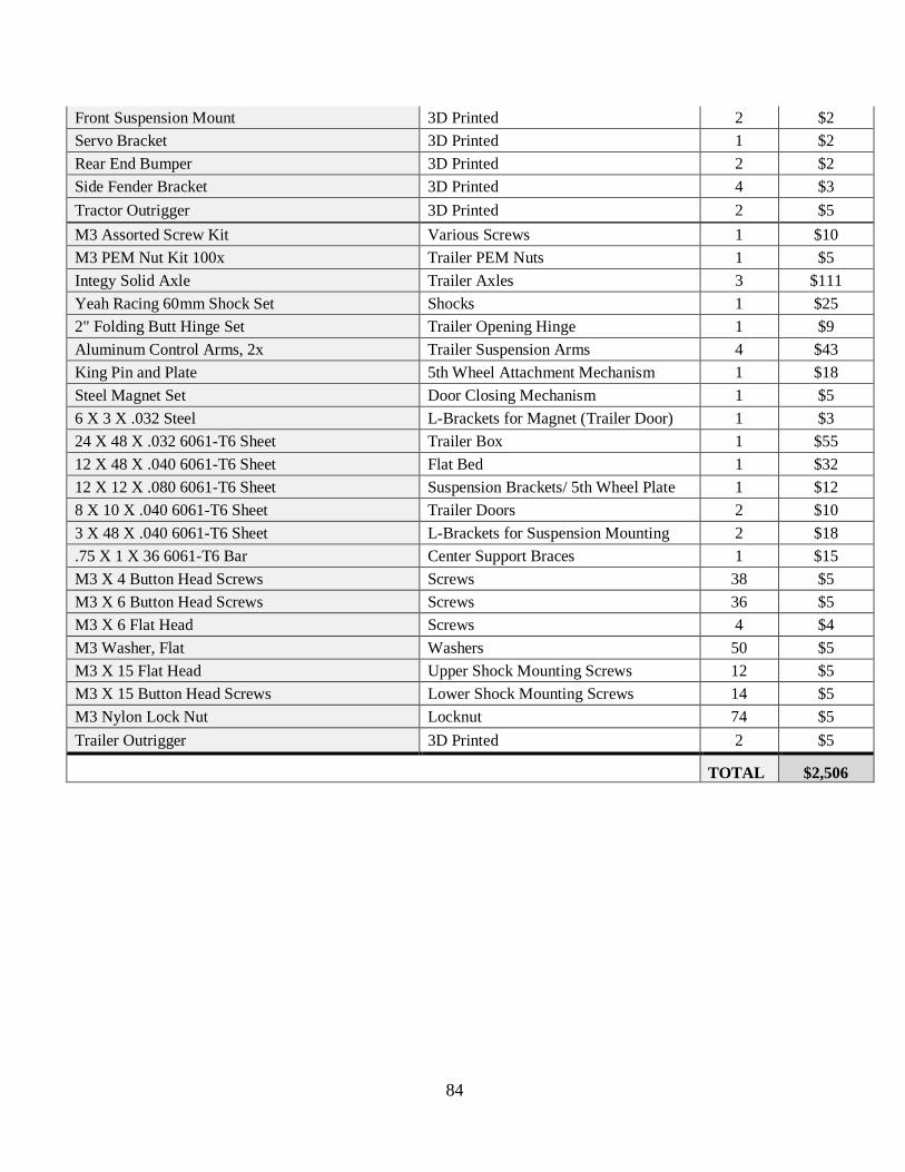
84
Front Suspension Mount 3D Printed 2 $2
Servo Bracket 3D Printed 1 $2
Rear End Bumper 3D Printed 2 $2
Side Fender Bracket 3D Printed 4 $3
Tractor Outrigger 3D Printed 2 $5
M3 Assorted Screw Kit Various Screws 1 $10
M3 PEM Nut Kit 100x Trailer PEM Nuts 1 $5
Integy Solid Axle Trailer Axles 3 $111
Yeah Racing 60mm Shock Set Shocks 1 $25
2" Folding Butt Hinge Set Trailer Opening Hinge 1 $9
Aluminum Control Arms, 2x Trailer Suspension Arms 4 $43
King Pin and Plate 5th Wheel Attachment Mechanism 1 $18
Steel Magnet Set Door Closing Mechanism 1 $5
6 X 3 X .032 Steel L-Brackets for Magnet (Trailer Door) 1 $3
24 X 48 X .032 6061-T6 Sheet Trailer Box 1 $55
12 X 48 X .040 6061-T6 Sheet Flat Bed 1 $32
12 X 12 X .080 6061-T6 Sheet Suspension Brackets/ 5th Wheel Plate 1 $12
8 X 10 X .040 6061-T6 Sheet Trailer Doors 2 $10
3 X 48 X .040 6061-T6 Sheet L-Brackets for Suspension Mounting 2 $18
.75 X 1 X 36 6061-T6 Bar Center Support Braces 1 $15
M3 X 4 Button Head Screws Screws 38 $5
M3 X 6 Button Head Screws Screws 36 $5
M3 X 6 Flat Head Screws 4 $4
M3 Washer, Flat Washers 50 $5
M3 X 15 Flat Head Upper Shock Mounting Screws 12 $5
M3 X 15 Button Head Screws Lower Shock Mounting Screws 14 $5
M3 Nylon Lock Nut Locknut 74 $5
Trailer Outrigger 3D Printed 2 $5
TOTAL $2,506

85
Appendix I: Drawing Package
These are attached on the following pages.
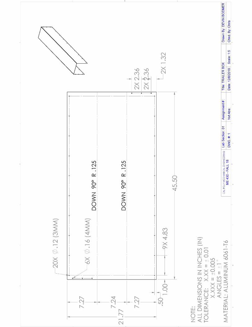
86
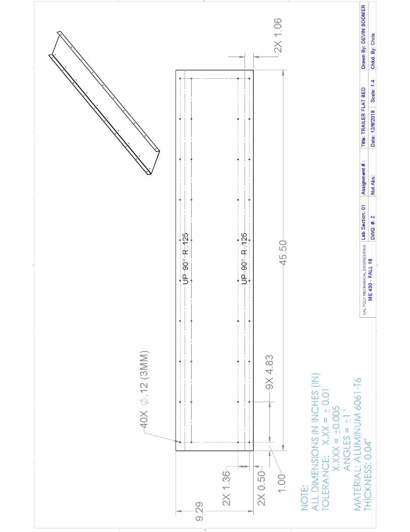
87
88
89
90
91
92
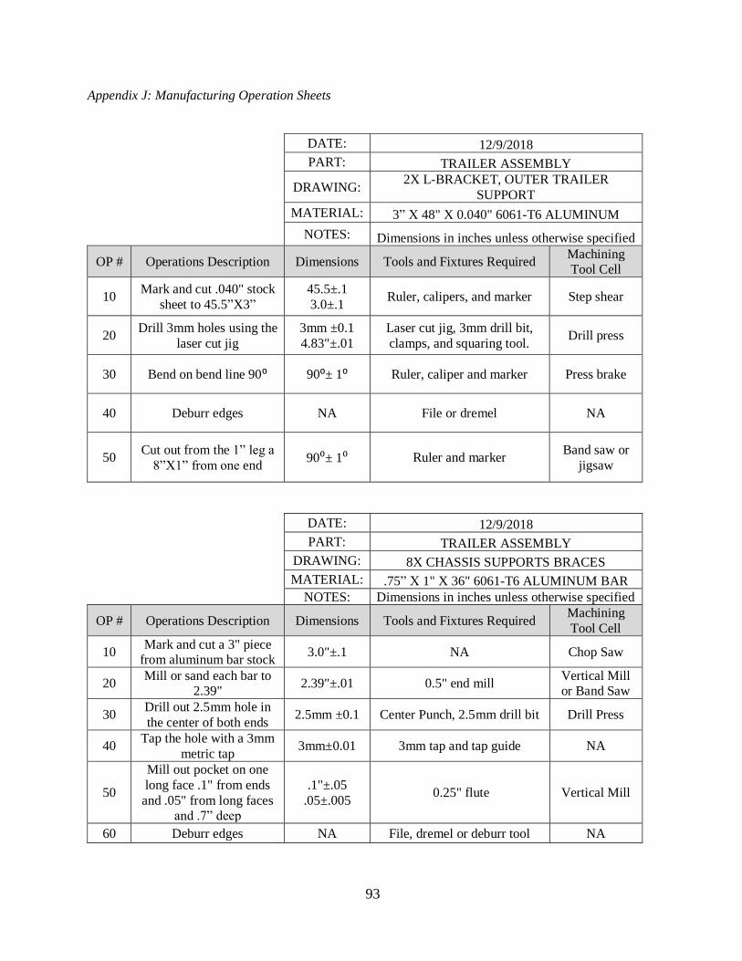
93
Appendix J: Manufacturing Operation Sheets
DATE: 12/9/2018 PART: TRAILER ASSEMBLY
DRAWING: 2X L-BRACKET, OUTER TRAILER
SUPPORT MATERIAL: 3” X 48" X 0.040" 6061-T6 ALUMINUM NOTES: Dimensions in inches unless otherwise specified
OP # Operations Description Dimensions Tools and Fixtures Required Machining
Tool Cell
10 Mark and cut .040" stock
sheet to 45.5”X3”
45.5±.1
3.0±.1 Ruler, calipers, and marker Step shear
20 Drill 3mm holes using the
laser cut jig
3mm ±0.1
4.83"±.01
Laser cut jig, 3mm drill bit,
clamps, and squaring tool. Drill press
30 Bend on bend line 90⁰ 90⁰± 1⁰ Ruler, caliper and marker Press brake
40 Deburr edges NA File or dremel NA
50 Cut out from the 1” leg a
8”X1” from one end 90⁰± 1⁰ Ruler and marker
Band saw or
jigsaw
DATE: 12/9/2018 PART: TRAILER ASSEMBLY DRAWING: 8X CHASSIS SUPPORTS BRACES MATERIAL: .75” X 1" X 36" 6061-T6 ALUMINUM BAR
NOTES: Dimensions in inches unless otherwise specified
OP # Operations Description Dimensions Tools and Fixtures Required Machining
Tool Cell
10 Mark and cut a 3" piece
from aluminum bar stock 3.0"±.1 NA Chop Saw
20 Mill or sand each bar to
2.39" 2.39"±.01 0.5" end mill
Vertical Mill
or Band Saw
30 Drill out 2.5mm hole in
the center of both ends 2.5mm ±0.1 Center Punch, 2.5mm drill bit Drill Press
40 Tap the hole with a 3mm
metric tap 3mm±0.01 3mm tap and tap guide NA
50
Mill out pocket on one
long face .1" from ends
and .05" from long faces
and .7” deep
.1"±.05
.05±.005 0.25" flute Vertical Mill
60 Deburr edges NA File, dremel or deburr tool NA
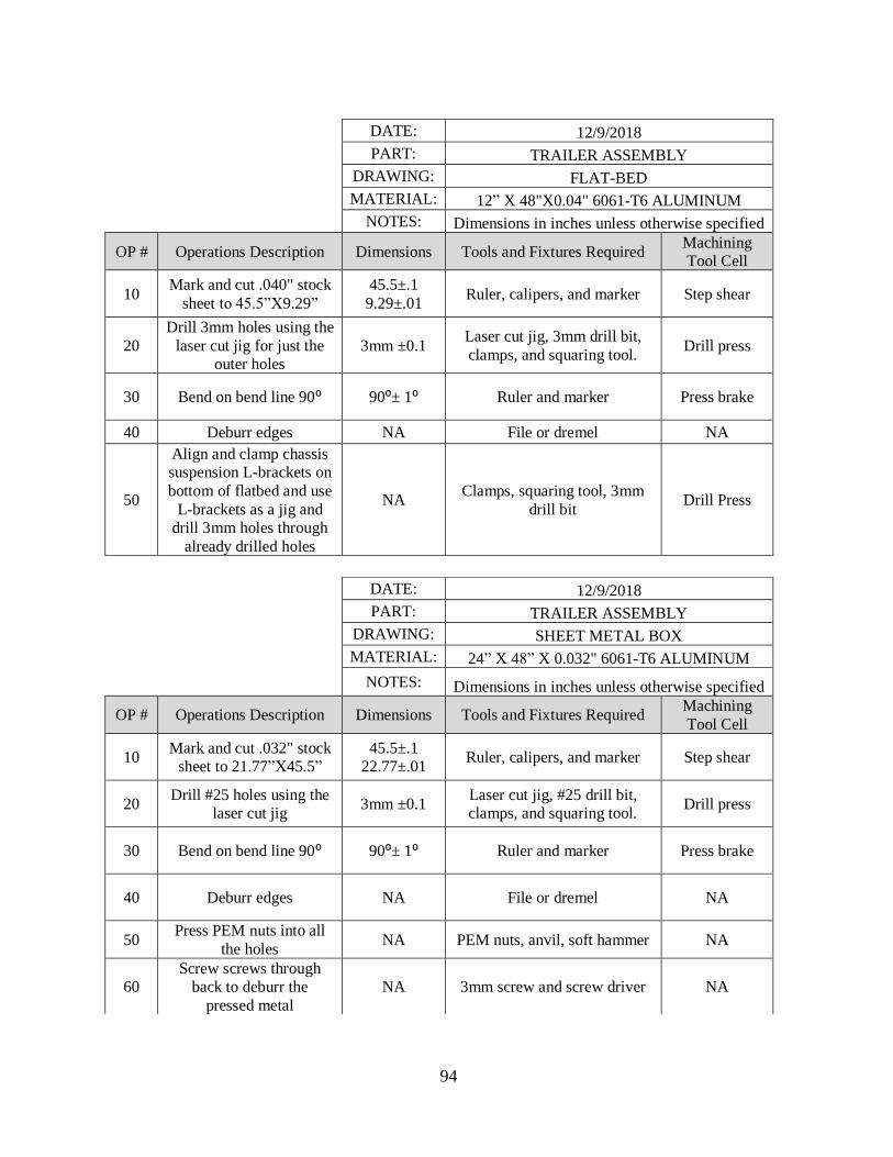
94
DATE: 12/9/2018
PART: TRAILER ASSEMBLY
DRAWING: FLAT-BED
MATERIAL: 12” X 48"X0.04" 6061-T6 ALUMINUM
NOTES: Dimensions in inches unless otherwise specified
OP # Operations Description Dimensions Tools and Fixtures Required Machining
Tool Cell
10 Mark and cut .040" stock
sheet to 45.5”X9.29”
45.5±.1
9.29±.01 Ruler, calipers, and marker Step shear
20
Drill 3mm holes using the
laser cut jig for just the
outer holes
3mm ±0.1 Laser cut jig, 3mm drill bit,
clamps, and squaring tool. Drill press
30 Bend on bend line 90⁰ 90⁰± 1⁰ Ruler and marker Press brake
40 Deburr edges NA File or dremel NA
50
Align and clamp chassis
suspension L-brackets on
bottom of flatbed and use
L-brackets as a jig and
drill 3mm holes through
already drilled holes
NA Clamps, squaring tool, 3mm
drill bit Drill Press
DATE: 12/9/2018 PART: TRAILER ASSEMBLY DRAWING: SHEET METAL BOX MATERIAL: 24” X 48” X 0.032" 6061-T6 ALUMINUM NOTES: Dimensions in inches unless otherwise specified
OP # Operations Description Dimensions Tools and Fixtures Required Machining
Tool Cell
10 Mark and cut .032" stock
sheet to 21.77”X45.5”
45.5±.1
22.77±.01 Ruler, calipers, and marker Step shear
20 Drill #25 holes using the
laser cut jig 3mm ±0.1
Laser cut jig, #25 drill bit,
clamps, and squaring tool. Drill press
30 Bend on bend line 90⁰ 90⁰± 1⁰ Ruler and marker Press brake
40 Deburr edges NA File or dremel NA
50 Press PEM nuts into all
the holes NA PEM nuts, anvil, soft hammer NA
60
Screw screws through
back to deburr the
pressed metal
NA 3mm screw and screw driver NA
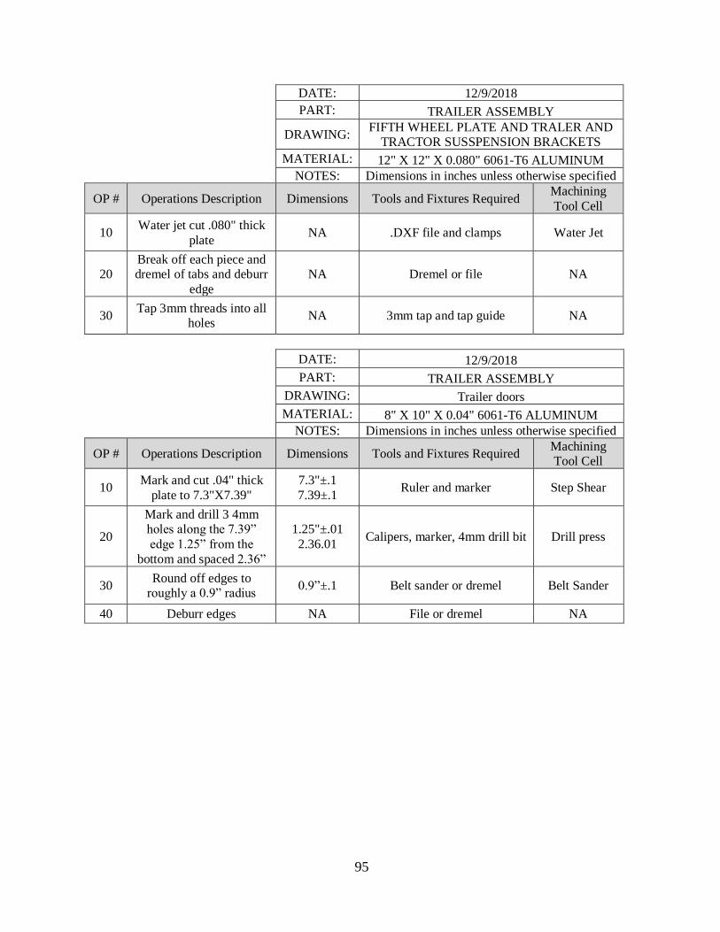
95
DATE: 12/9/2018
PART: TRAILER ASSEMBLY
DRAWING: FIFTH WHEEL PLATE AND TRALER AND
TRACTOR SUSSPENSION BRACKETS MATERIAL: 12" X 12" X 0.080" 6061-T6 ALUMINUM
NOTES: Dimensions in inches unless otherwise specified
OP # Operations Description Dimensions Tools and Fixtures Required Machining
Tool Cell
10 Water jet cut .080" thick
plate NA .DXF file and clamps Water Jet
20
Break off each piece and
dremel of tabs and deburr
edge
NA Dremel or file NA
30 Tap 3mm threads into all
holes NA 3mm tap and tap guide NA
DATE: 12/9/2018 PART: TRAILER ASSEMBLY DRAWING: Trailer doors MATERIAL: 8" X 10" X 0.04" 6061-T6 ALUMINUM
NOTES: Dimensions in inches unless otherwise specified
OP # Operations Description Dimensions Tools and Fixtures Required Machining
Tool Cell
10 Mark and cut .04" thick
plate to 7.3"X7.39"
7.3"±.1
7.39±.1 Ruler and marker Step Shear
20
Mark and drill 3 4mm
holes along the 7.39”
edge 1.25” from the
bottom and spaced 2.36”
1.25"±.01
2.36.01 Calipers, marker, 4mm drill bit Drill press
30 Round off edges to
roughly a 0.9” radius 0.9”±.1 Belt sander or dremel Belt Sander
40 Deburr edges NA File or dremel NA
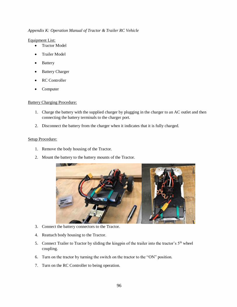
96
Appendix K: Operation Manual of Tractor & Trailer RC Vehicle
Equipment List:
• Tractor Model
• Trailer Model
• Battery
• Battery Charger
• RC Controller
• Computer
Battery Charging Procedure:
1. Charge the battery with the supplied charger by plugging in the charger to an AC outlet and then
connecting the battery terminals to the charger port.
2. Disconnect the battery from the charger when it indicates that it is fully charged.
Setup Procedure:
1. Remove the body housing of the Tractor.
2. Mount the battery to the battery mounts of the Tractor.
3. Connect the battery connectors to the Tractor.
4. Reattach body housing to the Tractor.
5. Connect Trailer to Tractor by sliding the kingpin of the trailer into the tractor’s 5th wheel
coupling.
6. Turn on the tractor by turning the switch on the tractor to the “ON” position.
7. Turn on the RC Controller to being operation.
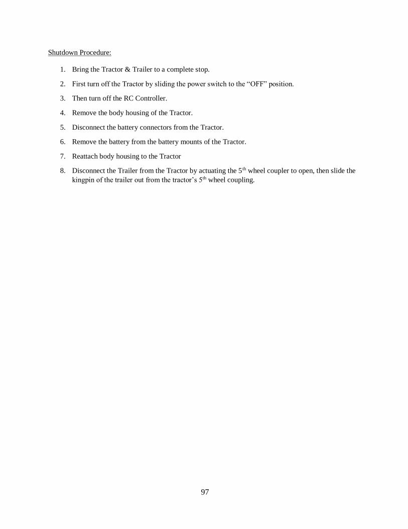
97
Shutdown Procedure:
1. Bring the Tractor & Trailer to a complete stop.
2. First turn off the Tractor by sliding the power switch to the “OFF” position.
3. Then turn off the RC Controller.
4. Remove the body housing of the Tractor.
5. Disconnect the battery connectors from the Tractor.
6. Remove the battery from the battery mounts of the Tractor.
7. Reattach body housing to the Tractor
8. Disconnect the Trailer from the Tractor by actuating the 5th wheel coupler to open, then slide the
kingpin of the trailer out from the tractor’s 5th wheel coupling.
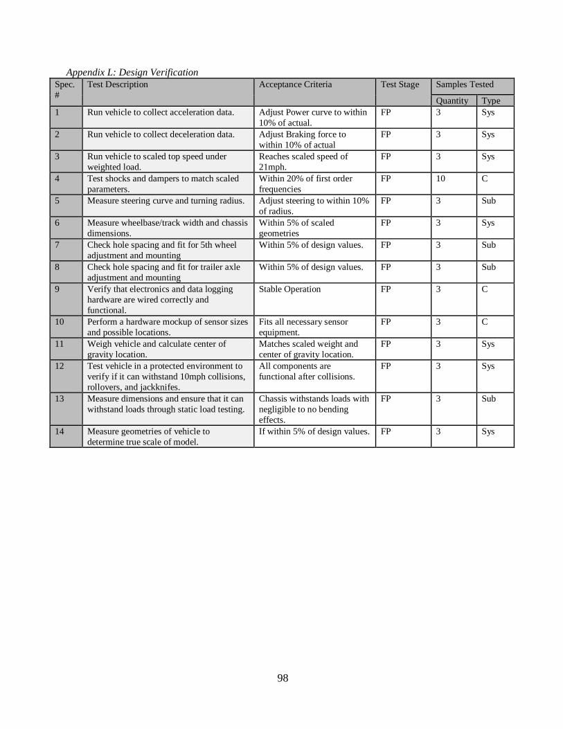
98
Appendix L: Design Verification
Spec.
#
Test Description Acceptance Criteria Test Stage Samples Tested
Quantity Type
1 Run vehicle to collect acceleration data. Adjust Power curve to within
10% of actual.
FP 3 Sys
2 Run vehicle to collect deceleration data. Adjust Braking force to
within 10% of actual
FP 3 Sys
3 Run vehicle to scaled top speed under
weighted load.
Reaches scaled speed of
21mph.
FP 3 Sys
4 Test shocks and dampers to match scaled
parameters.
Within 20% of first order
frequencies
FP 10 C
5 Measure steering curve and turning radius. Adjust steering to within 10%
of radius.
FP 3 Sub
6 Measure wheelbase/track width and chassis
dimensions.
Within 5% of scaled
geometries
FP 3 Sys
7 Check hole spacing and fit for 5th wheel
adjustment and mounting
Within 5% of design values. FP 3 Sub
8 Check hole spacing and fit for trailer axle
adjustment and mounting
Within 5% of design values. FP 3 Sub
9 Verify that electronics and data logging
hardware are wired correctly and
functional.
Stable Operation FP 3 C
10 Perform a hardware mockup of sensor sizes
and possible locations.
Fits all necessary sensor
equipment.
FP 3 C
11 Weigh vehicle and calculate center of
gravity location.
Matches scaled weight and
center of gravity location.
FP 3 Sys
12 Test vehicle in a protected environment to
verify if it can withstand 10mph collisions,
rollovers, and jackknifes.
All components are
functional after collisions.
FP 3 Sys
13 Measure dimensions and ensure that it can
withstand loads through static load testing.
Chassis withstands loads with
negligible to no bending
effects.
FP 3 Sub
14 Measure geometries of vehicle to
determine true scale of model.
If within 5% of design values. FP 3 Sys