Embed Size (px)
Citation preview

DAILY VEHICLEMY 2009RANGE BODYBUILDERS INSTRUCTIONS
EXPANSION MODULE
LIG
HT
RA
NG
E
ISSUE 2010

Publication Edited by:IVECO S.p.A.Technical ApplicationStrada delle Cascinette, 424/3410156 Torino (TO) - Italywww.iveco.com
Printed 603.95.231 - 1st ed. 12/2010
Publication produced for IVECO by
SATIZ TECHNICAL PUBLISHING
c/o Iveco - Customer Service
Lungo Stura Lazio, 15
10156 Torino - Italy

Printed 603.95.231 Base - 12/2010
Update data
DAILY MY 2009 - EXPANSION MODULEBodybuilders instructionsPrinted 603.95.231 - 1st ed.Base - 12/2010
UPDATE DATA
Section Description Page Revision date

Base - 12/2010 Printed 603.95.231
Update data

This publication provides the data, features and instructions for vehicle fitting and modifications.
It is intended for qualified, skill personnel. The Body Builder is responsible for designing the fitting, its modification and execution,and will have to ensure compliance with the provisions both of this publication and the law regulations in force.
Prior to carrying out any work, make sure you have the publication of the vehicle model on which you are about to work. Also makesure that all the accident-prevention equipment such as, for instance, goggles, helmet, gloves, boots, etc. as well as the working, liftingand handling equipment are available and in goodworking order. Finally, make sure that you operate on the vehicle in such conditionsas to ensure maximum safety.
The execution of the work by strictly complying with the above provisions, as well as the use of the components shown, ensure thatthe work is carried out correctly and safely.
Any change, modification or fitting not covered by this manual and not expressly authorized in written by IVECO will relieve thelatter of any responsibility and make, in particular, the vehicle guarantee null and void.
IVECO is available to provide all and every explanation required to carry out the work and also help you handle the cases not dealtwith in this publication.
After every single intervention, the functioning, efficiency and safety conditions established by IVECO shall be restored. Contact theIVECO service network for vehicle set-up, if necessary.
IVECO shall not be responsible for any change, modification or fitting concerning the vehicle.
The data and information contained in this publication may not be updated due to the changes made by IVECO, at any time, fortechnical or commercial reasons, or to make the vehicles comply with the law regulations in force in the different countries.
In the event of any discrepancy between the contents of this publication and the actual vehicle, please contact the Product Managerfor your market before carrying out any operations.
General danger
It includes the dangers of above described signals.
Danger of serious damage for the vehicle
Partial or complete nonobservanceof theseprescriptions can cause serious damages to the vehicle and sometimes guar-antee lapse too.
Environment protection
It indicates correct behaviour in order that vehicle use is environmentally friendly as much as possible.
Danger for persons
Missing or incomplete observance of these prescriptions can cause serious danger for persons’ safety.
Symbols - Warnings
!
Foreword
It indicates an additional explanation for a piece of information.NOTE
Printed 603.95.231 Base - 12/2010
Foreword

Page header and footer interpretation
Vehicle type Section title Section number -page number
Printnumber
Chapter title Basic edition -month year
Base - 12/2010 Printed 603.95.231
Foreword

Printed 603.95.231 Base - 12/2010
Index of section
INDEX OF SECTION
Section
Expansion Module - PTO 1
Expansion Module - Additional Functions 2
Expansion Module - CANOpen 3

Base - 12/2010 Printed 603.95.231
Index of section

EXPANSION MODULE - PTO 1-1DAILY MY 2009
Printed 603.95.231 Base - 12/2010
Index
Index
SECTION 1
Expansion Module - PTOPage
1. Abbreviations 1-3
2. Glossary 1-3
3. Principles 1-4
4. Types of power take-off (PTO) 1-4
4.1 Power take-off to the gearbox 1-4
4.2 Power take-off to the transmission 1-4
4.3 Power take-off to the engine 1-4
4.4 ”Transfer case output shaft PTO” power take-off 1-4
4.5 ”Transmission output shaft PTO” power take-off 1-4
4.6 “Electro-hydraulic” power take-off (PTO2 and PTO3) 1-4
5. Management of PTOs 1-5
5.1 Activation of the PTO 1-6
5.2 Standard PTO configuration supplied as default by IVECO 1-7
5.2.1 PTO1 on Manual Gearbox 1-7
5.2.2 PTO1 on Automatic Gearbox 1-8
5.3 PTO operation when errors are present (Degraded Mode) 1-8
5.4 Custom PTO configurations 1-9
5.4.1 Engagement restrictions 1-9
5.4.2 Disengagement conditions 1-10
5.4.3 Checks on the engine 1-11
5.4.4 Parameters that can only be set for PTO2 and PTO3 1-13
5.5 Standard parameters for PTO1 supplied by IVECO 1-14
6. Wiring Diagram 1-16
6.1 Fitters sockets for Expansion Module 1-16
6.2 Electrical connections for PTO2 and PTO3 connection 1-17

1-2 EXPANSION MODULE - PTO DAILY MY 2009
Base - 12/2010 Printed 603.95.231
Index

EXPANSION MODULE - PTO 1-3DAILY MY 2009
Printed 603.95.231 Base - 12/2010
Abbreviations
Abbreviations
1. Abbreviations
The following abbreviations are used in this section:
Table 1
Abbreviation MeaningPTO Power take-off
EM Expansion Module
B-CAN Low speed CAN (50 kbit/s)
C-CAN High Speed CAN (500 kbit/s)
VDB Vehicle Data Bus
ECU Electronic Control Unit
VF Vehicle Function
EDC16 Engine Control Unit
ESV1 Automatised gearbox
ABS8 Anti Blocking System
ESP8 Electronic Stability Program
TBD To be defined
TBC To be confirmedGeneral instructions for chassis modifications
2. Glossary
The following terms and symbols are used in this section:
Table 2
Terms and Symbols DefinitionBody Computer The main component of a Body electronics system. It acquires
inputs from the body electric/electronic components and itdrives the body electric/electronic components. It is also thegateway between the driveline data bus and the body data bus.
Instrument Cluster The display component.
Body Electronics Data Bus (B-CAN) It is a low speed CAN (50 kbit/s), compliant with the FIATNorm07320. It is the data bus that connects all the Body electronicsystems (Body Computer, Instrument Clusters, AirBag,Infotainment Nodes, etc.)
Vehicle Data Bus (VDB) A high speed CAN (250 kbit/s), compliant with SAE J1939. Itis the data bus that connects all the Powertrain electronicsystems (Engine management, Automatic transmission, Brakingsystems, etc.)

1-4 EXPANSION MODULE - PTO DAILY MY 2009
Base - 12/2010 Printed 603.95.231
Principles
Principles
3. Principles
Refer to Bodybuilders Instruction.
4. Types of power take-off (PTO)
Only one PTO can be fitted for each type of power take-off.
4.1 Power take-off to the gearbox
Refer to Bodybuilders Instruction.
The power take-off on the gearbox is only electromechanical.
There are two PTO management methods, to be defined with IVECO: management with own control unit or with EM.
4.2 Power take-off to the transmission
Refer to Bodybuilders Instruction.
4.3 Power take-off to the engine
Refer to Bodybuilders Instruction.
4.4 ”Transfer case output shaft PTO” power take-off
To define with IVECO.
4.5 ”Transmission output shaft PTO” power take-off
To define with IVECO.
4.6 “Electro-hydraulic” power take-off (PTO2 and PTO3)

EXPANSION MODULE - PTO 1-5DAILY MY 2009
Printed 603.95.231 Base - 12/2010
Management of PTOs
Management of PTOs
5. Management of PTOs
!Operations performed in amanner that does not complywith IVECO’s instructions as set outbelow or carried out by non-qualified staff can result in serious damage to the on-boardsystems. Thismay compromise safety, reliability and the correct operation of the vehicle andmay cause associated damage that is not covered by the contractual warranty.
The PTO’s are managed directly by the Expansion Module (EM) control unit in Figure 1. The EM is able to manage up to threedifferent PTOs.
Power take-off PTO1 can be fitted solely and exclusively on the gearbox.
126269
Figure 1
EM CONTROL UNIT (located in the centre of the dashboard on the right-hand side)Different parameters can be configured for each PTO by IVECO Customer Service:• engagement restrictions
• disengagement conditions
• control on engine (engine rpm request of maximum torque limit configuration or maximum rpm limit configuration)
The control parameter on the engine cannot be configured for a CNG engine.NOTE

1-6 EXPANSION MODULE - PTO DAILY MY 2009
Base - 12/2010 Printed 603.95.231
Management of PTOs
5.1 Activation of the PTO
A button in the middle of the dashboard in the driver’s cab engages and disengages the PTO1 (Figure 2). This is a rocker button.
A warning light on the button indicates the status of PTO1:
- warning light fixed off (a): PTO1 disengaged;
- warning light fixed on (b): PTO1 engaged;
- warning light flashing: transient stage from (a) → (b) or from (b)→ (a) in which the EM searches, respectively, to engage ordisengage PTO1.
Since the EM can control up to three PTO’s, up to three PTO controls (one button for PTO1 and two switches for PTO2 andPTO3) can be included in the dashboard. The switches for PTO2 and PTO3 are stable type and the responsibility of the Fitter. TheFitter must also see to the connections between PTO2 (and/or PTO3) and the Fitter connectors. For a more detailed description,refer to par. 6: ”Wiring Diagram”.
Figure 2
126270
Warning light
PTO1 button
If the PTO1 button is faulty, a new one can be purchased directly through IVECO. The associated item code is given in the table.

EXPANSION MODULE - PTO 1-7DAILY MY 2009
Printed 603.95.231 Base - 12/2010
Management of PTOs
5.2 Standard PTO configuration supplied as default by IVECO
IVECO supplies the EM control unit standard with just PTO1 configured, the wiring and PTO button. Power take-off PTO1 canbe fitted solely and exclusively on the gearbox.
5.2.1 PTO1 on Manual Gearbox
Engagement of the PTO
The purpose of this action is to prepare equipment for work.
During execution of the operating sequence the driver is assisted to prevent steering errors.
The correct operations to perform to engage the PTO are:
a) stop the motion of the vehicle
b) check/ engage neutral gear if the operation is prepared with the vehicle at a standstill or engage the gear that the equipmentmust operate in
c) depress the clutch pedal
d) press and release the button on the dashboard that controls engagement of the power take-off (Figure 2 - Page 1-6)
e) the warning light that indicates that power take-off is engaged begins to flash until it becomes permanently on. PTO is engagedwhen the warning light (Figure 2 - Page 1-6) is permanently on
f) at this point the clutch can be released. Power take-off is correctly engaged.
If there is an ”Engagement Restriction” (engagement restriction conditions, see paragraph 5.4.1) the PTO will not engage. An errormessage will appear on the instrument panel to advise the driver. The error will be displayed at each subsequent attempt to engagePTO as long as the cause(s) of the restriction remains. When the cause of the restriction has been eliminated PTO can be engagedby following the procedure described above.
Disengagement of the PTO
The correct operations to be carried out are:
a) stop the operation of the equipment
b) press the button that controls engagement of the power take-off (Figure 2 - Page 1-6)
c) the warning light that indicates that power take-off is engaged begins to flash it switches off. PTO is disengaged when the warninglight (Figure 2) is permanently off
g) at this point the power take-off is correctly disengaged.
If there is ”Shutoff Condition” (disengagement condition, see paragraph 5.4.2) the PTO will automatically disengage. An errormessage will appear on the instrument panel to advise the driver. When the cause of the disengagement condition has beeneliminated PTO can be engaged by following the procedure described above and keeping it switched on.
!The power take off can be switched off only when no torque is applied to it (either engine ortransmission).

1-8 EXPANSION MODULE - PTO DAILY MY 2009
Base - 12/2010 Printed 603.95.231
Management of PTOs
5.2.2 PTO1 on Automatic Gearbox
Engagement of the PTO
The purpose of this action is to prepare equipment for work.
During execution of the operating sequence the driver is assisted to prevent steering errors.
The correct operations to perform to engage the PTO are:
a) stop the motion of the vehicle
b) check/ engage neutral gear
c) press the button on the dashboard that controls engagement of the power take-off (Figure 2 - Page 1-6)
d) the warning light that indicates that power take-off is engaged begins to flash until it becomes permanently on. PTO is engagedwhen the warning light (Figure 2 - Page 1-6) is permanently on
e) power take-off is correctly engaged.
Disengagement of the PTO
The correct operations to be carried out are:
a) stop the operation of the equipment
b) press the button that controls disengagement of the power take-off (Figure 2- Page 1-6)
c) the warning light (Figure 2 - Page 1-6) that indicates that power take-off is engaged switches off. PTO is disengaged
d) at this point the vehicle can be moved.
!The power take off can be switched off only when no torque is applied to it (either engine ortransmission).
5.3 PTO operation when errors are present (Degraded Mode)
”Degraded Mode” allows the driver to progress the PTO operation despite an error being present.
The system enters Degraded Mode only if at least one disengagement condition has previously been configured.
The errors that start Degraded Mode are:
- a missing CAN message
- an engagement signal in which the value is outside of the permitted range
In this mode, the error detected is displayed on the instrument panel. When the error message appears the driver must press theMODE button. A message will then be displayed on the instrument panel inviting the driver to decidewhether they wish to continueto operate the PTO under their own command or terminate the operation, automatically disengaging the PTO.
If no instruction is given within the Degraded_Mode_Timeout period (20 seconds), the PTO operation will be interruptedautomatically.

EXPANSION MODULE - PTO 1-9DAILY MY 2009
Printed 603.95.231 Base - 12/2010
Management of PTOs
5.4 Custom PTO configurations
Depending on foreseen vehicle use Fitters are required to contact IVECO Customer Service, for carrying out the necessaryExpansion Module control unit programming for operation of a PTO.Keeping to the following instructions the Fitter will be able to organise system configuration in advance.If special adjustments are necessary, the Fitter can programme them, for each individual power take off, by contacting IVECOCustomer Service.Except for express warnings, the following instructions apply to each individual power take-off.
5.4.1 Engagement restrictions
Engagement restrictions are used if the user wishes to impede engagement of the PTO to check (or not) the set conditions.The restriction conditions are considered as such only if they have a temporary duration of a few seconds or more. When this timehas elapsed the EM control unit will detect the presence of the restriction. A warning message will be displayed and engagementwill not take place.The table below provides a list of all possible engagement restrictions. The user chooses which restrictions to enter for their ownapplication from those indicated.
Table 3
Parameter PossibleRestriction 1
PossibleRestriction 2
Brake Depressed Not depressedHand brake Activated Not activated
Clutch pedal (#) Depressed Not depressedCoolant temperature 40 -150˚C
Neutral gear engaged (+) In neutral Gear engagedReverse Engaged Not engaged
Open circuit on the pressure switch if fitted on PTO2(§)Shortcircuit to earth on the pressure switch if
fitted on PTO2(§)Open circuit on the relevant pressure switch
fitted on PTO3(§)Shortcircuit to earth on the pressure switch if
fitted on PTO3(§)Low engine oil pressureMin rpm for engagementMax rpm for engagement
Min vehicle speedMax vehicle speed
Lower gear engaged(+)Higher gear engaged(+)
(#) only for manual gearbox(+) for automatic gearbox only(§) for electrical connections see chapter 6: “Wiring Diagram”
These conditions can be modified only by IVECO Customer Service.NOTE

1-10 EXPANSION MODULE - PTO DAILY MY 2009
Base - 12/2010 Printed 603.95.231
Management of PTOs
5.4.2 Disengagement conditions
The disengagement conditions are those in which the PTO switches itself off automatically. The disengagement conditions areconsidered as such only if they have a temporary duration of a few seconds or more. When this time has elapsed the EM controlunit will detect the presence of the disengagement condition. A warning message will be displayed on the instrument panel and thePTO will automatically disengage.
NOTE The automatic disengagement by the EM depends on the PTO load. In some situations, when thewarning message is displayed in the instrument panel, the PTO is not switched off automatically. Inthis case it is necessary to:a) with a manual transmission
• with the vehicle stationary, operate the clutch• with the vehicle moving, engage neutral
b) with an automatic transmission• with the vehicle moving, engage neutral
The table below contains the list of possible disengagement conditions; the user chooses the one for their application.
Table 4
Parameter Possible conditiondisengagement 1
Possible conditiondisengagement 2
Brake Depressed Not depressedHand brake Activated Not activated
Clutch pedal (#) Depressed Not depressedCoolant temperature 40 -150˚C
Neutral gear engaged (+) In neutral Gear engagedReverse Engaged Not engaged
Open circuit on the pressure switch if fitted on PTO2(§)Shortcircuit to earth on the pressure switch if
fitted on PTO2(§)Open circuit on the relevant pressure switch
fitted on PTO3(§)Shortcircuit to earth on the pressure switch if
fitted on PTO3(§)Low engine oil pressureMin rpm for disengagementMax rpm for disengagement
Min vehicle speedMax vehicle speed
Lower gear engaged(+)Higher gear engaged(+)
Clutch slipping percentage(@)
(#) only for manual gearbox(+) for automatic gearbox only(§) for electrical connections see chapter 6: “Wiring Diagram”(@) condition applicable only with automatic gearbox and only for stationary PTO
These conditions can be modified only by IVECO Customer Service.NOTE

EXPANSION MODULE - PTO 1-11DAILY MY 2009
Printed 603.95.231 Base - 12/2010
Management of PTOs
5.4.3 Checks on the engine
When the PTO is engaged the following checks on the engine are connected:
- rpm request (not available on CNG engine)
- configuration of maximum rpm limit (not available on CNG engine)
- configuration of maximum torque limit (a limit at lower torque values than necessary to support idling should not be set for CNGengines, otherwise the engine will cut out).
During the ”rpmrequest” check the engine speed cannot be changedusing theCruiseControl and/orthe accelerator pedal.
NOTE
The engine control ends when the PTO is disengaged.
The parameter PTO[x]_SwActCfg (x = 1, 2, 3 represents the PTO involved) defines whether to associate the control on the enginewith the pressure of the button for PTO engagement:
Table 5
Parameter ConfigurationPTO[x]_SwActCfg No control requested
Engine control requested as soon as the PTO engagement button is pressed
!When the aforementioned parameter is set andwhen there areengagement restrictions, theengine control is applied for a certain period of time (a few seconds) until the EM control unitno longer detects the restriction.
These conditions can be modified only by IVECO Customer Service.NOTE
The parameter PTO[x]_FbkActCfg (x = 1, 2, 3 refers to the PTO involved) defines whether to associate the engine control tothe successful engagement of the PTO, therefore only after the engine has sent a positive feedback to the EM.
Table 6
Parameter ConfigurationPTO[x]_FbkActCfg No control requested
Engine control requested only after the PTO has been successfully engaged.
These conditions can be modified only by IVECO Customer Service.NOTE

1-12 EXPANSION MODULE - PTO DAILY MY 2009
Base - 12/2010 Printed 603.95.231
Management of PTOs
The parameter PTO[x]TSC1field1_4 (x = 1, 2, 3 represents the PTO involved) defines the type of control to be requested.Specifically:
Table 7
Parameter Type of requestPTO[x]TSC1field1_4 No request/ Disabled
Rpm request
Torque request
Torque limit request/ rpm limit request
These conditions can be modified only by IVECO Customer Service.NOTE
The parameter PTO[x]TSC1field5 (x = 1, 2, 3 represents the PTO involved) based on the configuration set throughPTO[x]TSC1field1_4, indicates:
Table 8
Parameter Type of control selected throughPTO[x]TSC1field1_4 Meaning of PTO[x]TSC1field5
PTO[x]TSC1field5 Control in rpm Engine speed value requested
Torque/rpm limit request Engine speed limit value requested
If the PTO is not stopped, the control in rpm is not performed.NOTE
These conditions can be modified only by IVECO Customer Service.NOTE

EXPANSION MODULE - PTO 1-13DAILY MY 2009
Printed 603.95.231 Base - 12/2010
Management of PTOs
The parameter PTO[x]TSC1field6 (x = 1, 2, 3 represents the PTO involved) based on the configuration selected throughPTO[x]TSC1field1_4, indicates:
Table 9
Parameter Type of control selected throughPTO[x]TSC1field1_4 Meaning of PTO[x]TSC1field5
PTO[x]TSC1field6 Control in torque Engine torque value requested
Torque/rpm limit request Limit value required by the engine torque
These conditions can be modified only by IVECO Customer Service.NOTE
5.4.4 Parameters that can only be set for PTO2 and PTO3
Engagement Timeout
If power take-offs PTO2 and PTO3 require a greater engagement time than two seconds, it is possible to act on the EngagementTimeout parameter PTO[x]_ERtimeout (x = 2, 3 represents the PTO involved) that stabilises the time level outside of which anengagement restriction condition (if configured) is considered as such.
The EM control unit assesses the outcome of the PTO[x] engagement and, if engagement has not been successful, displays anyEngagement Timeout errors only once the ”Engagement Timeout”. time has elapsed.
The PTO[x]_ERtimeout parameter can be set by IVECO Customer Service.NOTE
Disengagement Timeout
If power take-offs PTO2 and PTO3 require a greater disengagement time than two seconds, it is possible to act on theDisengagement Timeout parameter PTO[x]_SCtimeout (x = 2 or 3 represents the PTO involved) that stabilises the time leveloutside of which a disengagement restriction condition (if configured) is considered as such.
The EM control unit assesses the outcome of the PTO[x] disengagement and, if disengagement has not been successful, displaysany Disengagement Timeout errors only once the Disengagement Timeout. time has elapsed.
Therefore, the EM control unit will detect the presence of the disengagement condition only once the Disengagement Timeouttime has elapsed Within 10 seconds a warning message will be displayed on the Instrument Panel and the PTO will automaticallydisengage.
The PTO[x]_SCtimeout parameter can be set by IVECO Customer Service.NOTE
1-14 EXPANSION MODULE - PTO DAILY MY 2009
Base - 12/2010 Printed 603.95.231
Management of PTOs
5.5 Standard parameters for PTO1 supplied by IVECO
Table 10
Parameters Description Manualgearbox Unit Automatic
gearbox Unit
Engagementrestrictions
Brake depressed no - no -Brake not depressed no - no -Hand brake activated no - no -Hand brake not activated no - no -Low engine oil pressure no - no -Clutch pedal depressed no - no -Clutch pedal not depressed yes - no -Neutral gear not engaged n.a - no -Reverse n.a - no -Open circuit on the pressure switch iffitted on PTO2
no - no -
Shortcircuit to earth on the pressureswitch if fitted on PTO2
no - no -
Open circuit on the relevant pressureswitch fitted on PTO3
no - no -
Shortcircuit to earth on the pressureswitch if fitted on PTO3
no - no -
Min rpm for engagement 750 rpm 750 rpmMax rpm for engagement 1300 rpm 1300 rpmMin vehicle speed no km/h no km/hMax vehicle speed no km/h no km/hLower gear engaged no gear no gearHigher gear engaged no gear no gearMaximum coolant temperature 110 ˚C 110 ˚C
Disengagementconditions
Brake depressed no - no -Brake not depressed no - no -Hand brake activated no - no -Hand brake not activated no - no -Low engine oil pressure no - no -Clutch pedal depressed yes - no -Clutch pedal not depressed no - no -Neutral gear not engaged n.a. - no -Reverse n.a. - no -Min rpm for disengagement 500 rpm 500 rpmOpen circuit on the pressure switch iffitted on PTO2
no - no -
Shortcircuit to earth on the pressureswitch if fitted on PTO2
no - no -
Open circuit on the relevant pressureswitch fitted on PTO3
no - no -
Shortcircuit to earth on the pressureswitch if fitted on PTO3
no - no -
Max rpm for disengagement 2000 rpm 2000 rpmMin vehicle speed no km/h no km/hMax vehicle speed no km/h no km/hLower gear engaged no gear no gearHigher gear engaged no gear no gearMaximum coolant temperature 110 ˚C 110 ˚CClutch slipping percentage no % no %

EXPANSION MODULE - PTO 1-15DAILY MY 2009
Printed 603.95.231 Base - 12/2010
Management of PTOs
Table 11
Parameters Description Manualgearbox Unit Automatic
gearbox Unit
Engine managementrequested with PTO1
No control requested yes-
yes-Engine control requested only after the
PTO has been successfully engaged.no no
Engine managementrequested on PTO1engagement feedback
No control requested yes-
yes-Engine control requested only after the
PTO has been successfully engaged.no no
Type of enginemanagement
No request/ Disabled yes
-
yes
-Rpm request no no
Torque request no no
Torque limit request/ rpm limit request no no
PTO[X]TSC1FIELD5 Control in rpm/ rpm limit request no rpm no rpm
PTO[X]TSC1FIELD6 Control in torque/ torque limit request no % no %
Key:
n.a. = not applicable
NOTE On CNG engines checks cannot be carried out on the engine (rpm request, configuration of themaximum rpm limit, configuration of the maximum torque limit).
During the ”rpmrequest” check the engine speed cannot be changedusing theCruiseControl and/orthe accelerator pedal.
NOTE

1-16 EXPANSION MODULE - PTO DAILY MY 2009
Base - 12/2010 Printed 603.95.231
Wiring Diagram
Wiring Diagram
6. Wiring Diagram
For effective and correct use by Fitters, IVECO has arranged specific connection points to be used for the added systems.
This is necessary to exclude any type of tampering or manipulation of the system to ensure the operating condition and thus themaintenance of the warranty itself.
6.1 Fitters sockets for Expansion Module
The Expansion Module control unit pins are available through two BLACK connectors shown below.
20 pin BLACK connector
114082
Figure 3

EXPANSION MODULE - PTO 1-17DAILY MY 2009
Printed 603.95.231 Base - 12/2010
Wiring Diagram
12 pin BLACK connector
114083
Figure 4
6.2 Electrical connections for PTO2 and PTO3 connection
The following figure shows the connections the Fitter must make for installing PTO2 and/or PTO3.
The Fitter must see to:
- fitting the switches (remember that these must be a stable type)
- the wiring between the PTO and the Fitters connectors
For the ground connection, the Fitter can choose to use:
- pin 17 of the Fitters BLUE connector
- the grounding points available on the vehicle as indicated in the Bodybuilders Manual

1-18 EXPANSION MODULE - PTO DAILY MY 2009
Base - 12/2010 Printed 603.95.231
Wiring Diagram
126271
Figure 5
Solenoid
Feedback
Pressure switch
Switch
EM FittersBLACK
20-pin socket
Solenoid
Feedback
Pressure switch
Switch
NOTE Non electro-hydraulic power take-offs can also be used. However, it must be remembered that:
- PTO activation control pins (pins 5 and 6) remain high active (12 V) until the relevant PTOengagement switch is ON.
- the feedback pins must always be present and equal to:
1→ PTO engaged
0→ PTO disengaged
- The status of the pressure switch (pins 9 and 10) can be used to configure a restriction on theengagement or a disengagement condition. In both cases the condition is that the pin is eitherconnected to the ground or open (see paragraphs: ”Engagement restrictions” and”Disengagement conditions”).

EXPANSION MODULE - PTO 1-19DAILY MY 2009
Printed 603.95.231 Base - 12/2010
Wiring Diagram
20-WAY BLACK EM CONNECTOR PIN
Table 12
BLACKconnector Pin Description Signal
5PTO2 actuator
(solenoid control for solenoid)High active output
Maximum deliverable current 1.5 A
6PTO3 actuator
(solenoid control for solenoid)High active output
Maximum deliverable current 3 A
7 PTO2 feedbackLow active input
Maximum current 10 mA
8 PTO3 feedbackLow active input
Maximum current 10 mA
9 PTO2 pressure switchLow active input
Maximum current 10 mA
10 PTO3 pressure switchLow active input
Maximum current 10 mA
16 Switch requested PTO2 engagementLow active input
Maximum current 10 mA
17 Switch requested PTO3 engagementLow active input
Maximum current 10 mA

1-20 EXPANSION MODULE - PTO DAILY MY 2009
Base - 12/2010 Printed 603.95.231
Wiring Diagram

EXPANSION MODULE - ADDITIONAL FUNCTIONS 2-1DAILY MY 2009
Printed 603.95.231 Base - 12/2010
Index
Index
SECTION 2
Expansion Module - Additional FunctionsPage
1. Abbreviations 2-3
2. Glossary 2-3
3. Other functions 2-4
3.1 Compatibility between PTO and additional functions 2-4
3.2 Run-Lock 2-5
3.2.1 Connections 2-5
3.2.2 Run-Lock engagement procedure with manual gearbox 2-7
3.2.3 Run-Lock disengagement procedure with manual gearbox 2-7
3.2.4 Run-Lock engagement procedure with automatic gearbox 2-7
3.2.5 Run-Lock disengagement procedure with automatic gearbox 2-8
3.3 Safety/Alarm function 2-8
3.3.1 Connections 2-8
3.3.2 Flashing of dipped/main beam headlights 2-10
3.3.3 Speed limit 2-10
3.4 Additional Lights 2-11
3.4.1 Connections 2-11
3.4.2 Additional lights 1 2-14
3.4.2.1 Flashing of additional lights 1 2-14
3.4.2.2 Flashing of dipped/main beam headlights 2-14
3.4.2.3 Speed limit 2-15
3.4.3 Additional lights 2 2-15
3.4.3.1 Flashing of additional lights 2 2-16
3.4.3.2 Flashing of dipped/main beam headlights 2-16
3.4.3.3 Speed limit 2-16
3.4.4 Scene lights 2-17
3.4.4.1 Speed limit 2-17
3.4.5 Tail lights 2-17

2-2 EXPANSION MODULE - ADDITIONAL FUNCTIONS DAILY MY 2009
Base - 12/2010 Printed 603.95.231
Index

EXPANSION MODULE - ADDITIONAL FUNCTIONS 2-3DAILY MY 2009
Printed 603.95.231 Base - 12/2010
Abbreviations
Abbreviations
1. Abbreviations
The following abbreviations are used in this section:
Table 1
Abbreviation MeaningPTO Power Take OFF
EM Expansion Module
KL15 Ignition Key
C-CAN High Speed CAN (500 kbit/s)
VDB Vehicle Data Bus
ECU Electronic Control Unit
VF Vehicle Function
EDC16 Engine Control Unit
ESV1 Automatic gearbox
ABS8 Anti Blocking System
ESP8 Electronic Stability Program
TBD To be Defined
TBC To be ConfirmedGeneral instructions for chassis modifications
2. Glossary
The following terms and symbols are used in this section:
Table 2
Terms and Symbols DefinitionBody Computer It is the main component of a Body electronics system. It
acquires inputs from the body electric/electronic componentsand it drives the body electric/electronic components. It is alsothe gateway between the driveline data bus and the body databus
Instrument Cluster It is the visualisation component.
Body Electronics Data Bus (B-CAN) It is a low speed CAN (50 kbit/s) compliant to the FIAT Norm07320. It is the data bus that connects all the Body electronicsystems (Body Computer, Instrument Clusters, AirBag,Infotainment Nodes, etc.)
Vehicle Data Bus (VDB) A high speed CAN (250 kbit/s), compliant with SAE J1939. Itis the data bus that connects all the Powertrain electronicsystems (Engine management, Automatic transmission, Brakingsystems, etc.)
Vehicle Functions All functions present in the vehicle electronic architecture

2-4 EXPANSION MODULE - ADDITIONAL FUNCTIONS DAILY MY 2009
Base - 12/2010 Printed 603.95.231
Other functions
Other functions
3. Other functions
The Expansion Module makes available additional functions:• Run-Lock
• Safety / Alarms
• Additional Lights
3.1 Compatibility between PTO and additional functions
It is not possible to use all functions of the Expansion Module (PTO and additional functions) simultaneously.
Each line of the following table indicates themaximumpermitted configuration, bearing in mind that the sum of the electrical currentsassociated with the functions used should NOT exceed 10 A.
However, it must be remembered that:
- additional lights 1 are incompatible with the use of PTO3
- additional lights 2 are incompatible with the use of PTO2
Table 3
No. PTO1 PTO2 PTO3 Rearlights
Additionallights 1
Additionallights 2
Scenelights Run-Lock
Dippedbeamsflash
1 X X
2 X X X X
3 X X X X
4 X X X X X X
5 X X X X X X
6 X X X X X X
7 X X X X X X
8 X X X X X
9 X X X X X X
10 X X X X
11 X X X X
12 X X X X
13 X X X X
14 X X X X
15 X X X
16 X X X
17 X X X X
18 X X X X
19 X X X X
20 X X X X
21 X X X X

EXPANSION MODULE - ADDITIONAL FUNCTIONS 2-5DAILY MY 2009
Printed 603.95.231 Base - 12/2010
Other functions
3.2 Run-Lock
The Run Lock allows the engine to keep running even when the key has been removed.
For the Run-Lock control to be considered valid, the vehicle must be in the following situation:
Table 4
Type of gearbox Conditions required for activation of the Run-Lock
MANUALVehicle at standstill(vehicle speed = 0)
Gearbox in neutral withclutch not depressed
Parking brake on
AUTOMATICVehicle at standstill(vehicle speed = 0
Gearbox in neutral Parking brake on
3.2.1 Connections
The following figure shows the connections to be made in order to use the Run-Lock function. Switch is low active.
The Expansion Module control unit pins are available for the Fitter through the two BLACK connectors. Refer to Section 1”Expansion Module - PTO”, paragraph 6.1 ”Fitter sockets for Expansion Module” to see them illustrated.
The Fitter must see to:
• installing the switch
• its connection to pin 11 of the EM Fitters BLACK 20-pin connector
• the connection between pin 20 of the EM Fitters BLACK 20-pin connector and pin 5 of the Fitters BLUE 12-pin connector
For the ground connection, the Fitter can choose to use:
• pin 17 of the Fitters BLUE connector
• the grounding points available on the vehicle as indicated in the Bodybuilders Manual

2-6 EXPANSION MODULE - ADDITIONAL FUNCTIONS DAILY MY 2009
Base - 12/2010 Printed 603.95.231
Other functions
126272
Figure 1
Run-Lock relay
EM FittersBLACK 20-pinconnector
Run-Lock switch
FittersBLUE 12-wayconnector
20-WAY BLACK EM CONNECTOR PIN
Table 5
BLACKconnector Pin Description Signal
11 Run-Lock switchLow active input
Maximum deliverable current 10 mA
20 Run-Lock relayHigh active output
Maximum deliverable current 1 A
12-WAY BLUE CONNECTOR PIN
Table 6
BLUEconnector pin Description Signal
5 Automatic keyMax input 500 mA
Simulates initial key rotation by providing apositive signal (key position ON)

EXPANSION MODULE - ADDITIONAL FUNCTIONS 2-7DAILY MY 2009
Printed 603.95.231 Base - 12/2010
Other functions
3.2.2 Run-Lock engagement procedure with manual gearbox
The correct procedure for engaging the Run-Lock is:
a) engine running
b) park the vehicle
c) check the gearbox is in/engage neutral (clutch not depressed)
d) engage the parking brake
e) operate the Run-Lock switch
f) remove the key.
NOTE During operation of Run-Lock mode, the engine will be shut down if one of the followingdisengagement conditions is detected:
• clutch depressed
• parking brake released
• vehicle speed > 0 km/h
3.2.3 Run-Lock disengagement procedure with manual gearbox
The correct procedure for disengaging the Run-Lock is:
a) turn the key to position 2
b) return the Run-Lock switch to OFF position.
3.2.4 Run-Lock engagement procedure with automatic gearbox
The correct procedure for engaging the Run-Lock is:
a) engine running
b) park the vehicle
c) check the gearbox is in/engage neutral
d) engage the parking brake
e) operate the Run-Lock switch
f) remove the key.
During operation of Run-Lock mode, the engine will be shut down if one of the followingdisengagement conditions is detected:
• gearbox not in neutral
• parking brake released
• vehicle speed > 0 km/h
NOTE
2-8 EXPANSION MODULE - ADDITIONAL FUNCTIONS DAILY MY 2009
Base - 12/2010 Printed 603.95.231
Other functions
3.2.5 Run-Lock disengagement procedure with automatic gearbox
The correct procedure for engaging the Run-Lock is:
a) turn the key to position 2
b) return the Run-Lock switch to OFF position.
3.3 Safety/Alarm function
The Safety/Alarm function can be applied in all cases in which the vehicle is under attack. In this situation the engine is switchedoff or limited to a certain number of revs; the activation of the flashing dipped headlights is possible.
Safety mode is turned on by operating the Alarm State switch.
The Expansion Module will apply a different strategy according to whether the vehicle is parked (stationary) or in motion. The detailsare as follows:
a) with vehicle at a standstill
• the engine will be turned off and immobilised andmaybe started up only and exclusively if the alarm state switch is turnedOFF
• both dipped headlights will flash (a flashing period equal to 1 second is set by default).
b) with vehicle in motion
• the speed will be limited to a default level of 30 km/h• once the vehicle has been stopped, stationary vehicle management will begin to operate
• both dipped headlights will flash (a flashing period equal to 1 second is set by default).
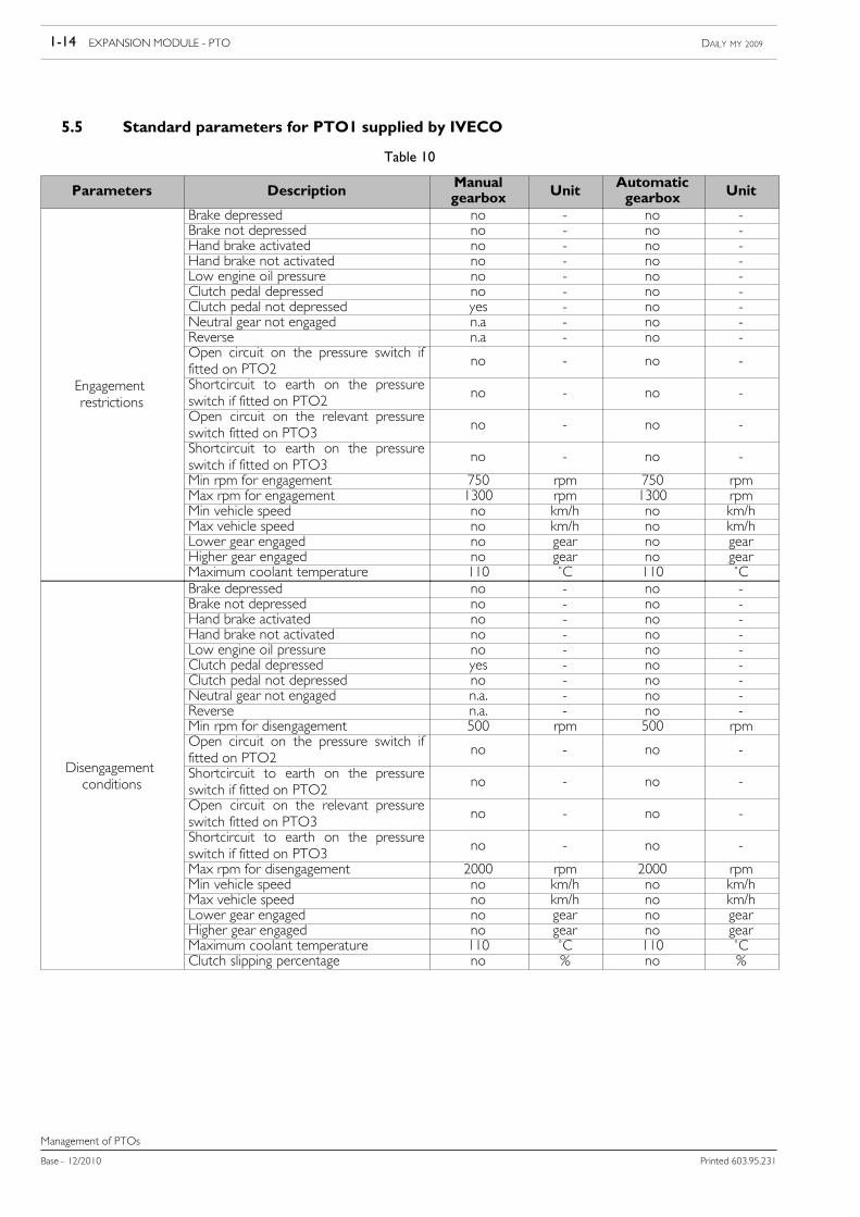
3.3.1 Connections
The following figure shows the connections to be made in order to use the Alarm function. Switch is high active.
The Expansion Module control unit pins are available for the Fitter through the two BLACK connectors. Refer to Section 1”Expansion Module - PTO”, paragraph 6.1 ”Fitter sockets for Expansion Module” to see them illustrated.
The Fitter must see to:
• installing the switch
• its connection to pin 4 of the EM control unit Fitters BLACK 12-pin connector and pin 6 of the Fitters BLUE 20-pinconnector
• the connection between pin 7 of the EM Fitters BLACK 12-pin connector and pin 2 of the Fitters BLUE 20-pin connector
If low beam flashing is required, the Fitter must see to:
• installing the two relays for the dipped headlights
• connecting the relays on the same line that runs from the dipped headlight relay on the normal production vehicle (relayT01 is present on the fuse box and under-dashboard relay) toward the headlights
IVECO Customer Service should disable the diagnosis of relay T01.NOTE
For the ground connection the Fitter can choose to use:
• pin 17 of the Fitters BLUE connector;
• the grounding points available on the vehicle as indicated in the Bodybuilders Manual.

EXPANSION MODULE - ADDITIONAL FUNCTIONS 2-9DAILY MY 2009
Printed 603.95.231 Base - 12/2010
Other functions
126273
Figure 2
Alarm switch
EM FittersBLACK 12-pinconnector
Engine shut-down command
FittersBLUE 20-pinconnector
Right dipped headlightrelay
Left dipped headlightrelay
12-WAY BLACK EM CONNECTOR PIN
Table 7
Connector pinBLACK Description Signal
1 Right dipped beam relayHigh active outputMaximum current 1 A
2 Left dipped beam relayHigh active outputMaximum current 1 A
4 Alarm activation control switch High active input
7 Engine shut-down command.High active output
Maximum deliverable current 1 A
20-WAY BLUE CONNECTOR PIN
Table 8
Connector pinBLUE Description Signal
2 Engine shut-downInput
Maximum current 10 mA
6 Battery positive15 A max output positive protected by fuse
present on dashboard node F32

2-10 EXPANSION MODULE - ADDITIONAL FUNCTIONS DAILY MY 2009
Base - 12/2010 Printed 603.95.231
Other functions
3.3.2 Flashing of dipped/main beam headlights
When the Alarm function is activated, the dipped headlights or the main beam headlights can also flash at the same time.Bear in mind that, irrespective of the type of lights chosen, the flashing is interrupted if the dipped headlights are activated via thesteering column switch unit.
A flashing period can also be configured:
• flashing time is normally enabled and is equal to 1 second;
• the minimum configurable period corresponding to maximum frequency is 0.5 seconds.
If the additional lights 1 and/or the additional lights 2 and/or the Alarm function are configured andif for each of these functions there has been a request for the flashing of the dipped headlights, thesystem takes the flashing time as the shortest period or the maximum frequency.
NOTE
The flashing period may only be modified by IVECO Customer Service.NOTE
3.3.3 Speed limit
The speed limit for the Alarm function is set at 30 km/h as standard, but it can be changed. Bear in mind that the limit cannotbe increased beyond the level set by the Speed Limiter.
If the additional lights 1 and/or additional lights 2 and/or the Alarm function and/or the backgroundlights are configured, and if for each of them there has been a requestfor a speed limit, the systemwill always use the minimum limit.
NOTE
The speed limit may only be modified by IVECO Customer Service.NOTE

EXPANSION MODULE - ADDITIONAL FUNCTIONS 2-11DAILY MY 2009
Printed 603.95.231 Base - 12/2010
Other functions
3.4 Additional Lights
The Additional Light function offers the user the option of installing various additional lights managed directly by the ExpansionModule control unit:
• additional lights 1
• additional lights 2
• scene lights
• tail lights
3.4.1 Connections
The following figure shows the connections to be made in order to use the additional light function.
All the switches are high active.
The Expansion Module control unit pins are available for the Fitter through two BLACK connectors. Refer to Section 1 ”ExpansionModule - PTO”, paragraph 6.1 ”Fitter sockets for Expansion Module” to see them illustrated.
The Fitter must see to:
• installing the switches
• installing the white light relays
• connection of the switches to the pins of the EM Fitters BLACK connectors
• connection of the relay to the pins of the EM Fitters BLACK connectors
• Installing the lights
If low beam flashing is required, the Fitter must see to:
• installing the two relays for the dipped headlights
• connecting the relays on the same line that runs from the dipped headlight relay on the normal production vehicle (relayT01 is present on the fuse box and under-dashboard relay) toward the headlights
IVECO Customer Service should disable the diagnosis of relay T01.NOTE
For the ground connection the Fitter can choose to use:
• pin 17 of the Fitters BLUE connector
• the grounding points available on the vehicle as indicated in the Bodybuilders Manual

2-12 EXPANSION MODULE - ADDITIONAL FUNCTIONS DAILY MY 2009
Base - 12/2010 Printed 603.95.231
Other functions
126274
Figure 3
EM FittersBLACK 20-pinconnector
Right brake light 21 W
EM FittersBLACK 12-pinconnector
Right direction indicator 21 W
Left brake light 21 W
Left direction indicator 21 W
Additional lights 2 21 W
Additional lights 1 36 W
Spot lights switch
Additional Lights 1 switch
Additional Lights 2 switch
Right low beam relay
Left low beam relay
Side lights 10 W
Scene lights relay

EXPANSION MODULE - ADDITIONAL FUNCTIONS 2-13DAILY MY 2009
Printed 603.95.231 Base - 12/2010
Other functions
20-WAY BLACK EM CONNECTOR PIN
Table 9
BLACKconnector Pin Description Signal
1 21 W right brake light commandHigh active output
Maximum current 1.5 A
2 21 W right direction indicator commandHigh active output
Maximum current 1.5 A
3 21 W left brake light commandHigh active output
Maximum current 1.5 A
4 21 W left direction indicator commandHigh active output
Maximum current 1.5 A
5 21 W Additional light commandHigh active output
Maximum current 1.5 A
6 36 W Additional light 1 commandHigh active outputMaximum current 3 A
12 White light switchLow active input
Maximum current 10 mA
13 Additional light switch 1Low active input
Maximum current 10 mA
14 Additional light switch 2Low active input
Maximum current 10 mA
12-WAY BLACK EM CONNECTOR PIN
Table 10
BLACKconnector Pin Description Signal
1 Right low beam relayHigh active outputMaximum current 1 A
2 Left low beam relayHigh active outputMaximum current 1 A
8 10 W side light commandHigh active outputMaximum current 1 A
9 White light relay commandHigh active outputMaximum current 1 A

2-14 EXPANSION MODULE - ADDITIONAL FUNCTIONS DAILY MY 2009
Base - 12/2010 Printed 603.95.231
Other functions
3.4.2 Additional lights 1
For example, the additional lights 1 can be the blue ambulance and Police lights.
The maximum power consumption for Additional lights 1 is 3 A, while the maximum power is 36 W.
Additional lights 1 are incompatible with the use of PTO3.
The additional lights 1 can be linked to different functions, all configurable by Fitter request:
• flashing of additional lights 1• flashing of dipped headlights• speed limit when additional lights 1 are ON• speed limit when additional lights 1 are OFF.
Additional lights 1 are incompatible with the use of PTO3.NOTE
3.4.2.1 Flashing of additional lights 1
It is possible to configure a period of flashing for additional lights 1, taking into account that:
- flashing is normally disabled, meaning that the lights remain fixed when switched on
- the minimum configurable period corresponding to maximum frequency is 0.5 seconds.
The flashing period may only be modified by IVECO Customer Service.NOTE
3.4.2.2 Flashing of dipped/main beam headlights
When the additional lights 1 are activated, the dipped headlights or the main beam headlights may also flash at the same time.Bear in mind that, irrespective of the type of lights chosen, the flashing is interrupted if the dipped headlights are activated via thesteering column switch unit.
A flashing period can also be configured:
- flashing is normally disabled
- the minimum configurable period corresponding to maximum frequency is 0.5 seconds.
NOTE If the additional lights 1 and/or the additional lights 2 and/or theAlarm function are configuredand if for each of these functions there has been a request for the flashing of the dipped headlights,the system takes the flashing time as the shortest period or the maximum frequency.
NOTE
The flashing period may only be modified by IVECO Customer Service.NOTE

EXPANSION MODULE - ADDITIONAL FUNCTIONS 2-15DAILY MY 2009
Printed 603.95.231 Base - 12/2010
Other functions
3.4.2.3 Speed limit
It is possible to configure a speed limit when the lights are ON and/or when the lights are OFF.
This option is normally disabled.
If the additional lights 1 and/or additional lights 2 and/or the Alarm function and/or the backgroundlights are configured, and if for each of them there has been a requestfor a speed limit, the systemwill always use the minimum limit.
NOTE
The speed limits may only be modified by IVECO Customer Service.NOTE
Additional lights 1 are incompatible with the use of PTO3.NOTE
3.4.3 Additional lights 2
For example, additional lights 2 may take the form of blue ambulance and Police lights.
Additional lights 2 are incompatible with the use of PTO2.
The maximum power consumption for additional lights 2 is 1.5 A, while the maximum power is 21 W.
The additional lights 1 can be linked to different functions, all configurable by Fitter request:
• flashing of additional lights 2
• flashing of dipped headlights
• speed limit when additional lights 2 are ON
• speed limit when additional lights 2 are OFF
Additional lights 2 are incompatible with the use of PTO2.NOTE

2-16 EXPANSION MODULE - ADDITIONAL FUNCTIONS DAILY MY 2009
Base - 12/2010 Printed 603.95.231
Other functions
3.4.3.1 Flashing of additional lights 2
It is possible to configure a period of flashing for additional lights 2, taking into account that:
- flashing is normally disabled, meaning that the lights remain fixed when switched on
- the minimum configurable period corresponding to maximum frequency is 0.5 seconds.
The flashing period may only be modified by IVECO Customer Service.NOTE
3.4.3.2 Flashing of dipped/main beam headlights
When the additional lights 2 are activated, the dipped headlights or the main beam headlights may also flash at the same time.Bear in mind that, irrespective of the type of lights chosen, the flashing is interrupted if the dipped headlights are activated via thesteering column switch unit.
A flashing period can also be configured:- flashing is normally disabled
- the minimum configurable period corresponding to maximum frequency is 0.5 seconds.
If the additional lights 1 and/or the additional lights 2 and/or the Alarm function are configured andif for each of these functions there has been a request for the flashing of the dipped headlights, thesystem takes the flashing time as the shortest period or the maximum frequency.
NOTE
The flashing period may only be modified by IVECO Customer Service.NOTE
3.4.3.3 Speed limit
It is possible to configure a speed limit when the lights are ON and/or when the lights are OFF.
This option is normally disabled.
If the additional lights 1 and/or additional lights 2 and/or the Alarm function and/or the backgroundlights are configured, and if for each of them there has been a requestfor a speed limit, the systemwill always use the minimum limit.
NOTE
The speed limits may only be modified by IVECO Customer Service.NOTE
Additional lights 2 are incompatible with the use of PTO2.NOTE

EXPANSION MODULE - ADDITIONAL FUNCTIONS 2-17DAILY MY 2009
Printed 603.95.231 Base - 12/2010
Other functions
3.4.4 Scene Lights
Maximum power consumption for scene lights is 1 A.
Scene lights may be associated with various functions:
• speed limit when scene lights are ON
• speed limit when scene lights are OFF
3.4.4.1 Speed limit
It is possible to configure a speed limit when the lights are ON and/or when the lights are OFF.
This option is normally disabled.
If the additional lights 1 and/or additional lights 2 and/or the Alarm function and/or the backgroundlights are configured, and if for each of them there has been a requestfor a speed limit, the systemwill always use the minimum limit.
NOTE
The speed limit may only be modified by IVECO Customer Service.NOTE
3.4.5 Tail lights
Tail lights consist of:
- right-hand direction indicator
- left-hand direction indicator
- right brake light
- left brake light
- side lights
As indicated in the Figure 1 in the paragraph 3.2.1 “Connections”, tail lights may be installed provided that the maximum powerof each individual light is as follows:
- turn signals: 21 W
- brake lights: 21 W
- side lights: 5 W
The lights do not work with the key OFF and maximum power consumption is 7 A.

2-18 EXPANSION MODULE - ADDITIONAL FUNCTIONS DAILY MY 2009
Base - 12/2010 Printed 603.95.231
Other functions

EXPANSION MODULE - CANOpen 3-1DAILY MY 2009
Printed 603.95.231 Base - 12/2010
Index
Index
SECTION 3
Expansion Module - CANOpenPage
1. Abbreviations 3-3
2. Glossary 3-4
3. CANOpen 3-5
3.1 CANOpen communication 3-6
3.2 Object dictionary (OD) 3-6
3.3 Communication model 3-8
3.3.1 COB-ID communication objects 3-8
3.3.1.1 Service Data Objects (SDO) 3-10
3.3.1.2 Process Data Objects (PDO) 3-10
3.3.1.3 Predefined communication objects 3-11
3.3.1.3.1 SYNC Object 3-11
3.3.1.3.2 Time Stamp Object 3-12
3.3.1.3.3 Emergency Object 3-12
3.4 Network management (NMT service) 3-14
3.4.1 Heartbeat 3-16
3.4.2 IVECO instructions for vehicle CANOpen network and CANOpen communication 3-16
3.5 CANOpen objects and CAN messages available for the Fitter 3-16
3.5.1 DSP 413-3 objects 3-17
3.5.2 DSP 413-5 objects 3-19
3.5.3 DSP 413-6 objects 3-20
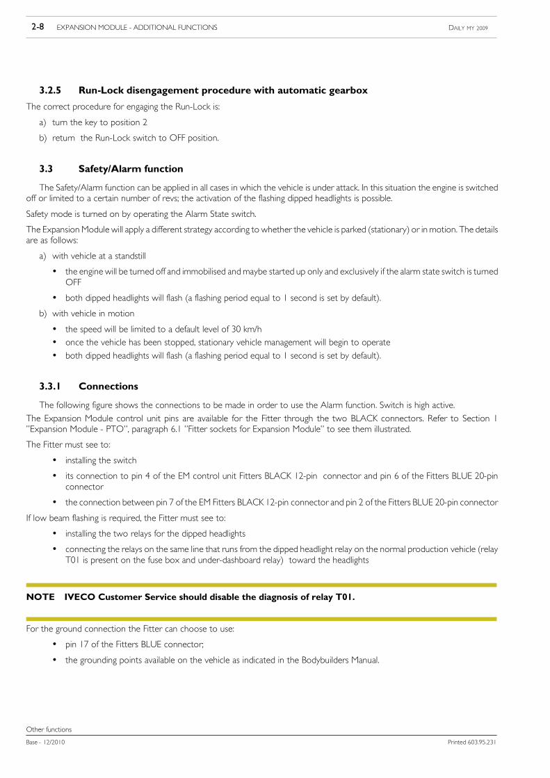
3.6 Description of functions settable by the Fitter 3-24
3.6.1 PTO engagement/release request 3-24
3.6.1.1 Feedback 3-25
3.6.2 PTO engagement/release enablement 3-26
3.6.3 Engine control requests 3-28
3.6.3.1 RPM request/maximum rpm limit 3-30

3-2 EXPANSION MODULE - CANOpen DAILY MY 2009
Base - 12/2010 Printed 603.95.231
Index
Page
3.6.3.1.1 Restrictions on rpm request/maximum rpm limit 3-30
3.6.3.2 Torque request 3-31
3.6.3.2.1 Torque request restrictions 3-31
3.6.3.3 Maximum vehicle speed configuration 3-32
3.6.3.3.1 Restrictions on maximum vehicle speed configuration 3-32
3.6.3.4 Multiple request management/Priorities 3-33
3.7 Wiring diagram 3-34
3.7.1 Expansion Module Fitters sockets for CANOpen 3-34
3.7.2 Electrical connections for the CANOpen connection 3-35

EXPANSION MODULE - CANOpen 3-3DAILY MY 2009
Printed 603.95.231 Base - 12/2010
Abbreviations
Abbreviations
1. Abbreviations
The following abbreviations are used in this section:
Table 1
Abbreviation MeaningPTO Power Take OFF
EM Expansion Module
RR Restriction request
RS Shutoff request
KL15 Ignition Key

3-4 EXPANSION MODULE - CANOpen DAILY MY 2009
Base - 12/2010 Printed 603.95.231
Glossary
Glossary
2. Glossary
The following terms and symbols are used in this section:
Table 2
Terms and Symbols DefinitionCAL (CAN Application Layer) Layer of communication higher than actual CAN bus, created
for CAN bus applications within open communication systems.CiA (CAN in Automation international users andmanufacturers group)
Association of manufacturers and users of devices with a CANinterface.
CANOpen Communication model defined by CiA and based on CAN busand CAL. To simplify the use of equipment of different brandson the same bus, the CANOpen CiA DS 301 communicationprotocol has defined a subset of CAL functions for applicationsin the automation technology field.
COB (Communication Object) On the CAN bus, data travel in the form of packets known ascommunication objects (COB) (another name used is CAN--Message = CAN message). Equipment connected to the CANbus can send and receive COBs.
COB-ID (COB-Identifier) Each COB is identified unequivocally by an identifier that is partof the COB. The CAN 2.0A specification supports up to 2048COBs, identified by means of l11 bit long identifiers. In this ser-vice start-up manual, the COB-IDs are always expressed inhexadecimal format.The list of COB-Identifiers, including all the COBs achievable via theCAN, is located in the object index of the relevant operating device.
EDS Electronic Data Sheet. Special file in ASCII format required toconfigure the CAN. The EDS file contains general informationon the node and its object dictionary.
EMCY (Emergency) The SINAMICS is equipped with an Emergency object to enableit to indicate errors in equipment or in the CAN bus to otherCANOpen bus nodes. The priority of this object is high and itprovides valuable information on operating equipment status.
NMT (Network Management) Responsible for initialisation, configuration and error processing.Node-ID (Node identification) Clearly identifies a device in the CANOpen network, i.e. all de-
vices must have their own Node-ID (bus address). The Node--IDs are always expressed in hexadecimal format.
PDO (Process Data Object) Used for quick access in real time to selected data. Images (map-ping) arepreconfiguredon somePDOs for certain variables or vari-able groups. The SDO is used for access to the remaining variables.
RPDO (Receive PDO) The PDO is received by the equipment (e.g. contains a positiondestination).
SDO (Service Data Object) The SDO permits access to all variables in a CANOpen device;for actuations, these take the form of actuation variables andCANOpen variables.The SDO is also used for the configuration. Use PDOs for fastaccess in real time to selected variables.
SYNC (synchronisation) SYNC is a special telegram for synchronising CAN devices withone another. Telegram priority is very high.
TPDO (Transmit PDO) PDO sent by the actuation (e.g. current position value).Variable Access to all actuation variables and CANOpen takes place
through variables.Access to variables can be via SDO or PDO.

EXPANSION MODULE - CANOpen 3-5DAILY MY 2009
Printed 603.95.231 Base - 12/2010
CANOpen
CANOpen
3. CANOpen
This chapter covers:
- a short overview of the main concepts and abbreviations used.
- a breakdown of CANOpen communication objects used in the Expansion Module.
Knowledge of the standards referred to below is assumed.
The Expansion Module CANOpen network operates in accordance with the following standards:
- CiA DS- 301 V4.02 (Application Layer and Communication Profile)
- CiA DR- 303-3 V1.2 (Indicator Specification)
- CiA DS- 306 V1.3: (Electronic data sheet specification for CANopen)
- CiA DS- 402 V2.0 (Device Profile for Drives and Motion Control)
- CIADS413-1 V2.0 (Device profile for truck gateways -Part 1:General definitions and default communicationobjects)
- CIA DS 4132-2 V2.0.2 (Device profile for truck gateways - Part 2: Brake and running gear devices)
- CiA DS- 413-3 V2.2 (Device profile for truck gateways Part 3: Other than brake and running gear devices)
- CiA DS- 413-5 V1.0.2 (Device profile for truck gateways Part 5: Superstructure objects)
- CiA DS- 413-6 V1.0.2 (Device profile for truck gateways Part 6: Framework for J1939-based networks)
Further information can be obtained from the official CAN in Automation association websitewww.can-cia.org.
NOTE

3-6 EXPANSION MODULE - CANOpen DAILY MY 2009
Base - 12/2010 Printed 603.95.231
CANOpen
3.1 CANOpen communication
CANOpen is a higher-layer protocol based on the CAN serial bus system. CANOpen requires the hardware of a connecteddevice to include a CAN receiver (CAN-transceiver) and a CAN controller as established by ISO 11898.
Communication profile CANOpen, CiADS-301 includes both cyclic communication and event-oriented communication thatmakesit possible to minimise the bus load, maintaining ultra-short reaction times. It is possible to achieve high communication performanceat relatively low speeds, thus reducing problems linked with EMC and wiring costs.
The physical medium of CANOpen is a differential pair bus line with common return compliant with ISO 11898. Bus length is limitedby communication speed (Baudrate) as follows:
Baudrate Maximum lengthof the bus
1 Mbit/s 25 m
500 kbit/s 100 m
250 kbit/s 250 m
125 kbit/s 500 m
100 kbit/s 1000 m
50 kbit/s 1000 m
3.2 Object dictionary (OD)
The central concept of CANOpen is based on the use of an Object Dictionary that collects data on the communication andapplication. Each object in the dictionary can be addressed using a 16-bit index and an 8-bit sub-index.
The arrangement of the Object Dictionary is as follows:
Table 3
Index (hexadecimal) Object0000 Not used
0001-001F Static Data Types
0020-003F Complex Data Types
0040-005F Manufacturer Specific Data Types
0060-007F Device Profile Specific Static Data Types
0080-009F Device Profile Specific Complex Data Types
00A0-0FFF Reserved for future uses
1000-1FFF Communication Profile Area
2000-5FFF Manufacturer Specific Profile Area
6000-9FFF Standardised Device Profile Area
A000-FFFF Reserved for future uses

EXPANSION MODULE - CANOpen 3-7DAILY MY 2009
Printed 603.95.231 Base - 12/2010
CANOpen
As you can see from the table, four segments can be distinguished in the OD:
- addresses lower than 1000 specify Data Types
- indexes between 1000 and 1FFF describe the Communication Profile Area, which contains communication parameterscommon to all devices
- indexes between 2000 and 5FFF include the Manufacturer Specific Profile Area, used by manufacturers to extend the basic setof device functions
- indexes between 6000 and 9FFF address the Standardised Device Profile Area, which describes all aspects relating to a specificdevise category. All devices of the same type must behave in the same manner.
More detailed descriptions of individual Data Types are given below:
- static Data Types are defined standard types such as Boolean logic, integers, floating points, strings etc. These objects arecommon to all devices and cannot therefore be read or written
- complex Data Types are predefined structures, consisting of standard data types common to all devices
- manufacturerData Types are predefined structures, consisting of standard data types but differ from complex data types becausethey relate to a specific device
- device Profiles can define further Data Types specific to their devices. In particular, static data types are defined by profilesincluded between indexes 0060 and 007F, while complex data types fall between 0080 and 009F.
The object dictionary is made up of six columns as follows:
Index Object Name Type Attribute M/O
where:
- Index indicates a position in the dictionary
- Object indicates the symbolic name of the object (e.g. DOMAIN, VAR, ARRAY, RECORD)
- Name contains a textual description
- Type indicates the data type (e.g. BOOLEAN, UNSIGNED8, SIGNED16)
- Attribute indicates the type of access from the bus to the device (e.g. Read/Write, ReadOnly, WriteOnly)
- M/O stands for Mandatory or Optional.

3-8 EXPANSION MODULE - CANOpen DAILY MY 2009
Base - 12/2010 Printed 603.95.231
CANOpen
Two mechanisms are available for accessing the above data and these are described below.
Table 4
PDO - Process Data Object SDO - Service Data Object
Channel used to transfer data relating to the process, i.e. in realtime
Channel used to transfer service date without pressing time re-quirements
Synchronous, asynchronous and event-governed messages Asynchronous messages
High priority identifiers (low CAN-ID) Low priority identifiers (high CAN-ID)
Optimised to exchange data effectively and quickly Optimised for various applications and the transfer of largequantities of non time-critical data
Direct correspondence with an object in the dictionary Access to an object indirectly via the index and sub-index
Transfer in a single message Transfer in several messages
3.3 Communication model
Although the CAN is multi-master type, the implementation of CANOpen requires a hierarchical master-slave type structuresin order to simplify system configuration and network management. This means that despite the continued existence of a CAN field-bus in which each node remains a master to all intents and purposes at Physical Layer and Data Link Layer, the link with the Applica-tion Layer requires the selection of an Application Master for each of the services provided. The same node may be the masterfor various functions, or there may be many different masters. It is also possible to change the master, even at each system cycle,according to the programmed master section algorithm (for example: the master for this service must be the node currently withthe lowest ID amongst the Active Error nodes. It does not go without saying, and is actually unlikely, that the same station will alwayssatisfy the required characteristics at each cycle, either because it may become faulty and enter active Passive Error status or becauseanother node with a lower ID may start operating correctly began, switching to Active Error node. In any case, this hierarchy is fullytransparent to lower layers.
Each master can have up two 127 slaves: Each node is identified by means of a unique 7 bit address (ID), within a range from 1 to127.
In the IVECO application, only one master and a single slave are used.NOTE
3.3.1 COB-ID communication objects
The CANOpen exchanges information via Communication Objects (COB): the CANOpen communication model specifies thevarious COBs, the communication services and the possible data transmission trigger modes. Each COB (communication object)is identified unequivocally by an identifier that is part of the COB. The CAN 2.0A specification supports up to 2048 COBs, identifiedby means of 11 bit long identifiers.
Synchronous and asynchronous message transmission is supported The former indicate that it is possible to acquire and implementinformation in a coordinated manner throughout the network. The predefined Communication Objects that are dedicated to thismessage type are known as Sync Message and Time Stamp Message. Conversely, asynchronous messages may be sent at any timebecause they do not need to respect any predefined synchronisation within the entire network.
The following table shows the predefined identifier allocation system.

EXPANSION MODULE - CANOpen 3-9DAILY MY 2009
Printed 603.95.231 Base - 12/2010
CANOpen
Table 5
Communicationsubjects
Functioncode Resulting COB-ID
OV index (hex) 1)
dec bin hex Description
NMT commands (NMT) 2) 0 0000 0 0 dec -
Sync message (SYNC) 1 0001 80 128 dec 1005, 1006, 1007
Alarm subjects(EMERGENCY)
1 0001 81-FF 129-255 dec 1014, 1015
Tx-PDO1 3 0011 181-FF 180 hex + Node-ID 1800
Rx-PDO1 4 0100 201-27F 200 hex + Node-ID 1400
Tx-PDO2 5 0101 281-2FF 280 hex + Node-ID 1801
Rx-PDO2 6 0110 301-37F 300 hex + Node-ID 1401
Tx-PDO3 7 0111 381-3FF 380 hex + Node-ID 1802
Rx-PDO3 8 1000 401-47F 400 hex + Node-ID 1402
Tx-PDO4 9 1001 481-4FF 480 hex + Node-ID 1803
Rx-PDO4 10 1010 501-57F 500 hex + Node-ID 1403
Tx-SDO 2) 11 1011 581-5FF 580 hex + Node-ID 1200
Rx-SDO 2) 12 1100 601-67F 600 hex + Node-ID 1200
Node surveillance(NMT Error Control) 2)
14 1110 701-77F 700 hex + Node-ID 100C, 100D
1) TheOV index for Tx and Rx PDOs depends on a number of actuation objects in the actuation group. Each additional actuation object begins with a descriptionwith an offset of 40 hex.For example: OV index for the first actuation object begins with TPDOs with 1800 hex and RPDOs with 1400 hex, each additional actuation object beginswith an offset of 40 hex -> 1840 hex and 1440 hex for the second actuation object, etc.
2) These COB-IDs are pre-set.
Network control objects (NMT, SYNC etc.) have the highest priority, followed by the PDOs and then by the SDOs; the priority is estab-lished in ”ANDwiredmode” on the bus layers at the time of transmission of the identifier (Carrier SenseMultiple Access / CollisionDetec-tion) in which the lower layer (dominant) takes precedence over the higher layer (recessive).

3-10 EXPANSION MODULE - CANOpen DAILY MY 2009
Base - 12/2010 Printed 603.95.231
CANOpen
3.3.1.1 Service Data Objects (SDO)
The Service Data Objects (SDO) allow access to the OD objects of all nodes, which can be configured in this way. Becausethe communication does not take place in real time, the priority of the SDOs is less than that of the PDOs, but of peer-to-peertype (not multicast). Each device can support more than a single SDO (a single SDO is the default).
The COB-IDs for SDO communication are:
- from master to slave: 600h + Node-ID
- from slave to master: 580h + Node-ID
3.3.1.2 Process Data Objects (PDO)
Data are exchanged in real time through Process Data Objects (PDO). PDOs correspond to objects in the OD of a device andare responsible for the interface with application objects.
Each Process Data Object is mapped exactly on one CAN frame so that they can be changed quickly without problems: The directconsequence is that the amount of data that can be transmitted via a PDO cannot exceed 8 bytes.
Transmitted PDOs are termed Transmit-PDO (T_PDO), while received PDOs are termed Receive-PDO (R_PDO).
Transmission mode
PDOs our cent from one device (PRODUCER) to another device (CONSUMER), or tomany other devices (broadcasting), withouta confirmation request. Each node in the network can listen to the message and decide individually whether to accept it or not bymeans of Acceptance Filtering.
For each node, it is possible to define up to four (Receive PDOs, from the Application Master to the device) and four (TransmitPDOs, from the device to the Application Master). In particular, the transmission of Process Data Objects by a slave node may betriggered by means of certain local events that affect the node or by means of a remote request from the master.
Synchronization of the device is made possible by a specific synchronization object, the SYNC Object (see Paragraph: PredefinedCommunication Objects), sent out periodically.
The transmission modes can be synchronous or asynchronous.

EXPANSION MODULE - CANOpen 3-11DAILY MY 2009
Printed 603.95.231 Base - 12/2010
CANOpen
The if following graph shows the principle of synchronism and asynchronism: Synchronous PDOs are sent within a predefined timewindow, immediately behind the SYNCObject, while asynchronous PDOs do not have any relationshipwith this window and there-fore with the SYNC Object.
126275
Figure 1
SYNC Object
Synchronous PDO
Synchronous PDO
Synchronous PDO
Asynchronous PDO
Asynchronous PDO
Window for synchronous objects
3.3.1.3 Predefined communication objects
Predefined communication objects are sub-divided into three categories:
- SYNC Object
- Time Stamp Object
- Emergency Object
These perform an important role even though their implementation is optional.
3.3.1.3.1 SYNC Object
The SYNC is sent periodically to all application devices (SYNCSlave) from the synchronisation device (SYNCMaster). This scansthe basic network clock and the time elapsing between one SYNC object and another is defined by the standard parameter Com-munication Cycle Period, that may be written through a configuration algorithm during the node built-up process A jitter time mayoccur during transmission, corresponding approximately to latency due to some other message sent immediately before the SYNC.
To ensure fast access to the bus, the priority attached to the SYNC Object is very high: Nodes that work in synchronous manner,use the SYNC to adjust their timing with that of the synchronization device. The associated details depend on the individual slaveand for particular applications, requiring higher synchronisation precision, the Time Stamp mechanism described in the followingparagraph may be used.

3-12 EXPANSION MODULE - CANOpen DAILY MY 2009
Base - 12/2010 Printed 603.95.231
CANOpen
3.3.1.3.2 Time Stamp Object
The time stamping mechanism is allocated the important task of correcting inevitable discrepancies between the clocks of thevarious processors present in the network. The Time StampObject is sent by the Time Stamp Producer to all the Time StampCon-sumers: this message contains the reference time expressed in milliseconds. Where necessary, it is possible to achieve a resolutionin the order of micro seconds.
3.3.1.3.3 Emergency Object
Emergency Objects are sent by a device that becomes aware of an internal error situation, to all other devices, with the highestpossible priority. A single emergency object may be transmitted for each error event in order not to block the traffic due to notifyingof the same fault more than once.
Table 6 - Emergency Error Codes
ERROR CODEhexadecimal MEANING
00XX Error Reset or No Error
10XX General error
20XX Current
21XX Current, input side
22XX Current, internal
23XX Current, output side
30XX Voltage
31XX Main voltage
32XX Internal voltage
33XX External voltage
40XX Temperature
41XX Environmental temperature
42XX Device temperature
50XX Device Hardware
60XX Device Software
61XX Internal Software
62XX User software
63XX Data Set
70XX Additional modules
80XX Monitoring
81XX Communication
90XX External error
F0XX Additional functions
FFXX Device specification

EXPANSION MODULE - CANOpen 3-13DAILY MY 2009
Printed 603.95.231 Base - 12/2010
CANOpen
The CANOpen Communication Profile defines errors (Table 6), the error log (Table 7) and additional information for the devicein question that specify the error status.
Table 7 - Error Log
BIT M/O MEANING0 M General error
1 O Current
2 O Voltage
3 O Temperature
4 O Communication error
5 O Specifies device profile
6 O Reserved
7 O Manufacturer’s specification
Like all other predefined communication objects, the Emergency Object is optional but, if a device implements it, at least two errorcodes must be supported, 00xx and 10xx (the only obligatory codes).

3-14 EXPANSION MODULE - CANOpen DAILY MY 2009
Base - 12/2010 Printed 603.95.231
CANOpen
3.4 Network management (NMT service)
Network management is carried out on the nodes and follows a master-slave structure. NMT imposes the use of one masterat a time during start-up/execution.NMT services allow the nodes to be initialised, started, monitored, reset or stopped.
If the device connected to the CANOpen network does not follow the instructions given in the para-graph below, the application should be agreed with IVECO.
NOTE
The following diagram shows the status diagram of a CANOpen node. Table 3 lists all the NMT services available for controllingstatus steps.
126276
Figure 2
Status diagram of a CANOpen node
Only SDO communication is possible in Pre-Operational status, whereas PDO is blocked.
PDO communication also takes place in Operational status.
NOTE

EXPANSION MODULE - CANOpen 3-15DAILY MY 2009
Printed 603.95.231 Base - 12/2010
CANOpen
Table 8 - Steps in status diagram
Steps Services(1) After Power-On the Control Unit automatically changes to initialisation status
(2) After initialisation, it changes to Pre-Operational
(3), (6) Start_Remote_Node command (CS = 128)
(4), (7) Enter_Pre-Operational_State command (CS = 128)
(5), (8) Stop_Remote_Node command (CS = 2)
(9), (10), (11) Reset_Node command (CS = 129
(12), (13), (14) Reset_Communication command (CS = 130)
As specified in the CANOpen Communication Profile, four main statuses are defined:
- Initialisation or Boot-up
- Pre-Operational
- Operational
- Stopped
Initialisation status (or Boot-up) is automatically reached after ignition and also after a reset command (node or communication).Once initialise Asian is complete, the node enters Pre-Operational mode independently.
In Pre-Operational status, it is possible to carry out parameterisation and ID allocation. SDO communication and emergency mess-ages are also permitted. The device may also be switched in Operational status.
In operational status, the node is able to communicate actively and the use of all types of CAN messages is permitted. The devicecan carry out the movement specified for the application.
At any moment during operation, the NMT master can force the device to stopped status.
The NMT services perform the following functions:
• Start Remote Node:Command for changing over from Pre-Operational status to Operational. The actuation is able to send and receive pro-cess data only in Operational status.
• Stop Remote Node:Command for changing from Pre-Operational to Stopped or from Operational to Stopped. In Stopped status, the nodecan only process NMT commands.
• Enter Pre Operational:command for changing from Operational to Stopped or Pre-Operational. In Pre-Operational status, the node cannotprocess PDOs. It may, however, be parameterised or controlled by means of SDOs. This means that it is also possibleto set reference values.
• Reset Node:command for changing fromOperational, Pre-Operational or Stopped to Initialisation. After the Reset Node command,all objects (1000 hex - 9FFF hex) are reset.
• Reset Communication:command for changing from Operational, Pre-Operational or Stopped to Initialisation. After the Reset Communicationcommand, all communication objects (1000 hex - 1FFF hex) are reset this to their original status.
TheNMT is described in detail in theCANOpen standard ”CiADS-301 V4.01 (Application Layer andCommunication Profile)”.
NOTE

3-16 EXPANSION MODULE - CANOpen DAILY MY 2009
Base - 12/2010 Printed 603.95.231
CANOpen
3.4.1 Heartbeat
CANOpen offers two alternatives for guaranteeing network operation:
• Node Guarding
• Automatic transmission of a Heartbeat message by network nodes
Only the Heartbeat message is implemented in the Expansion Module.
A node uses the Heartbeat to automatically transmit its communication status at regular intervals as evidence of its communicationcapability. The period between two Heartbeat messages can be configured by IVECO Customer Service on request of the User.
3.4.2 IVECO instructions for vehicle CANOpen network and CANOpen communication
At the time of the keyOFF/keyON transition, the fitter control unit which interfaces with the Expan-sionModule via theCANOpen shouldbe connected to theconnectedandshould start communicatingas quickly as possible (within a maximum time of 2 seconds).
NOTE
The Fitter should fit the 120 Ohm termination resistance on their wiring for the CANOpen networkbetween BB_CAN_H and BB_CAN_L in order to allow communication between their control unitand the Expansion Module.The Fitter device should never be physically disconnected from the CANOpen network after the keyON.If these instructions are not followed, the correct CANOpen communication by the ExpansionMod-ule cannot be guaranteed.
NOTE
3.5 CANOpen objects and CAN messages available for the Fitter
Using CANOpen the Fitter can have vehicle information through:
• CANOpen objects (DSP 413-3 and DSP 413-5 objects)
• CAN messages by means of a gateway on CANOpen (DSP 413-6 objects)
The CAN messages, grouped together in four functional groups, are enabled at Customer Service IVECO in a single package.
- FMS + Engine Torque
- Airbag
- Service + Doors + Light + Time
- PTO
No specific application is needed by Engineering.
Listed below are all the CANOpen objects available for the Fitter.
For details of each object, refer to the following standards:
- CiA DS- 413-3 V2.2 (Device profile for truck gateways Part 3: Other than brake and running geardevices)
- CiA DS- 413-5 V1.0.2 (Device profile for truck gateways Part 5: Superstructure objects)
- CiA DS- 413-6 V1.0.2 (Device profile for truck gateways Part 6: Framework for J1939-based networks)For resolutions, ranges and offsets of the various objects, refer to standard ISO11992-3.
For the composition of CAN messages by CiA DS 413-6 refer to standard SAEJ1939-71.

EXPANSION MODULE - CANOpen 3-17DAILY MY 2009
Printed 603.95.231 Base - 12/2010
CANOpen
3.5.1 DSP 413-3 objects
A specific application from Engineering is needed to enable the following items.
The requests should be sent to IVECO Customer Service (office: Workshop Methods and Diagnostics).
Table 9
Object index [HEX] Object name6105H Anti-theft device request
6107H Anti-theft device
610AH Percent clutch slip
610CH Current gear
610EH Accelerator pedal low idle switch
610FH Engine control allowed
6110H PTO control allowed
6111H Vehicle speed
6113H Engine speed
6115H Driver’s demand engine percent torque
6117H Actual engine percent torque
6119H Reference engine torque
611BH Percent load at current speed
611DH Maximum vehicle speed limit
611FH Engine speed upper limit
6121H Engine speed lower limit
6123H Engine coolant temperature warning
6124H Engine oil pressure warning
6127H Engine coolant temperature
612EH First clutch dependent PTO feedback
612FH Second clutch dependent PTO feedback
6130H Clutch independent PTO feedback
6131H First engine mounted PTO feedback
6132H Second engine mounted PTO feedback

3-18 EXPANSION MODULE - CANOpen DAILY MY 2009
Base - 12/2010 Printed 603.95.231
CANOpen
Table 10
Object index [HEX] Object name6133H Starter active6134H Engine running6135H Engine torque mode6136H First clutch dependent PTO switch6137H Second clutch dependent PTO switch6138H Clutch independent PTO switch6139H First engine mounted PTO switch613AH Second engine mounted PTO switch6140H Requested engine speed upper limit6144H Requested engine torque limit6146H Requested vehicle speed limit614AH Requested engine speed614CH Accelerator pedal position614EH Ambient air temperature6150H Fuel level warning
Table 11
Object index [HEX] Object name617BH Seconds617DH Minutes617FH Hours6181H Day6183H Month6184H Year6186H Local minute offset6188H Local hour offset618AH Left-hand stop light(s) command618BH Right-hand stop light(s) command618CH Left-hand direction indicator light(s) command618DH Right-hand direction indicator light(s) command618EH Left-hand rear light(s) command618FH Right-hand rear light(s) command6190H Left-hand rear fog light(s) command6191H Right-hand rear fog light(s) command6192H Left-hand reversing light(s) command6193H Right-hand reversing light(s) command6194H Left-hand side marker light(s) command6195H Right-hand side marker light(s) command61A0H Transmission output shaft PTO feedback61A1H Transfer case output shaft PTO feedback61A2H At least one PTO engaged61A3H Transmission output shaft PTO switch61A4H Transfer case output shaft PTO switch61A5H First clutch dependent PTO engagement consent61A6H Second clutch dependent PTO engagement consent61A7H Clutch independent PTO engagement consent61A8H First engine mounted PTO engagement consent

EXPANSION MODULE - CANOpen 3-19DAILY MY 2009
Printed 603.95.231 Base - 12/2010
CANOpen
Table 12
Object index [HEX] Object name61A9H Second engine mounted PTO engagement consent
61AAH Transmission output shaft PTO engagement consent
61ABH Transfer case output shaft PTO engagement consent
61ACH First clutch dependent PTO engagement consent - By Fitter
61ADH Second clutch dependent PTO engagement consent - By Fitter
61AEH Clutch independent PTO engagement consent - By Fitter
61AFH First engine mounted PTO engagement consent - By Fitter
61B0H Second engine mounted PTO engagement consent - By Fitter
61B1H Transmission output shaft PTO engagement consent - By Fitter
61B2H Transfer case output shaft PTO engagement consent - By Fitter
3.5.2 DSP 413-5 objectsA specific application from Engineering is needed to enable the following items.
The requests should be sent to IVECO Customer Service (office: Workshop Methods and Diagnostics).
Table 13
Object index [HEX] Object name6304H Electrical potential6306H Rated engine power6308H Rated engine speed630AH Engine oil level6317H Parking light command6318H Low beam command6319H High beam command631AH Stopping brake device active631CH Driver door open active631DH Co-driver door open active631EH Central door lock device active6320H Fuel filter clocked active6322H Air filter clocked active6328H Additional light device active (*)6331H Clutch closed state active6332H Clutch open state active (+)6336H Engine pre-heating active6337H Engine speed control upper limit allowed6339H Engine speed control allowed633AH Engine torque limit control allowed633CH Vehicle speed limit control allowed633EH Front fog light device request634AH KL15 status
(*) Additional Lights 1 ON or Additional Lights 2 ON
(+) Only for automatic gearbox

3-20 EXPANSION MODULE - CANOpen DAILY MY 2009
Base - 12/2010 Printed 603.95.231
CANOpen
3.5.3 DSP 413-6 objects
The following items, grouped together in four functional groups, are enabled at IVECO Customer Service in a single package
No specific application is needed by Engineering.
FMS + Engine Torque
Table 14
J 1939 message Object Name Object Index SignalsCCVS pg_VCAN_CCVS. 6427H Vehicle speed
Clutch switchBrake switchCruise Control activeCruise Control statePTO state
EEC2 pg_VCAN_EEC2 6426H
AP kickdown switchAP low idle switchAccelerator pedal (AP) positionPercent Load at current speed
Fuel Consuption pg_VCAN_LFC 6422H TotalFuelUsedDASH DISPLAY pg_generic_message_8 643DH Fuel Level
EEC1 pg_VCAN_EEC1 6425H
Engine / Retarder Torque ModeDrivers demand engine - percent torqueActual engine - percent torqueEngine SpeedSource address of controlling device for engine controlEngine Demand - Percent Torque
HOURS pg_generic_message_3 6438HTotalEngineHoursTotalEngineRevolutions
DTCO_BAM pg_generic_message_22 644BH Vehicle Identification Only in vehicles with Tachograph: VINDTCO_MPM pg_generic_message_23 644CH Vehicle Identification Only in vehicles with Tachograph: VIN
VDHR pg_VCAN_VDHR 642AHTotalDistanceOnly in vehicles with Tachograph: TripDistance
Service pg_generic_message_4 6439H
Service DistanceService Delay/Calendar Time BasedService Delay/Operational Time Based
TCO1 pg_VCAN_TCO1 6429H
In all vehicles:Output shaft speedVehicle speed
Only in vehicles with Tachograph:Drive recognizeDriver 2 working stateDriver 1 working stateOverspeedDriver card, driver 1Driver 1 time related stateDriver card, driver 2Driver 2 time related stateDirection indicatorTachograph performanceHandling informationSystem event
ENG_TEMP pg_VCAN_ET1 6428HEngine coolant temperatureFuel temperature
EEC3 pg_generic_message_9 643EH
Nominal friction - percent torqueEngine’s desired operating speedEngine’s operating speed asymmetry adjustment

EXPANSION MODULE - CANOpen 3-21DAILY MY 2009
Printed 603.95.231 Base - 12/2010
CANOpen
Manufacturer specific object
Table 15
Engine speed at idle PLC_TX_U161 2006H Eng Conf Bam engine speed at idle, point 1
Engine speed at high idle PLC_TX_U162 2006H Eng Conf Bam engine speed at high idle, point 6
Reference engine torque PLC_TX_U163 2006H Eng Conf Bam reference engine torque
REQUEST_PGN_BBIU2DTCO PLC_RX_U322 2003H Request for Vehicle Identification
REQUEST_PGN_BC2EDC16 PLC_RX_U323 2003H Request for Hours and Fuel Consumption
Request PGN
Table 16 below summarises the PNG codes to be used depending on the type of request.
Bear in mind that each time the EM goes to ”Operational” mode, starting from the second request, the value 0 must be writtenin the subject and then the code.
Table 16
Subject Type of request PGN code to be written
REQUEST_PGN_BBIU2DTCO Vehicle identification 0x00FEC0
REQUEST_PGN_BC2EDC16
(both Diesel and CNG)
Hours 0x00FEE5
Fuel consumption 0x00FEE9
Airbag
Table 17
J 1939 message Object Name Object Index Signals
MUX_info2 pg_generic_message_14 6443H
Driver seat belt reminder sts
Crash output sts

3-22 EXPANSION MODULE - CANOpen DAILY MY 2009
Base - 12/2010 Printed 603.95.231
CANOpen
Service + Doors + Light + Time
Table 18
J 1939 message Object Name ObjectIndex Signals
ENGINE_FLUID_LEVEL_PRESSURE pg_generic_message_16 6445HEngineOilLevel (not available if Service packnot installed)
MUX_info pg_generic_message_21 644AH
LowBeamlightsrequestHighbeamlightsrequestHighbeamflashlightsrequestRHSIndicatorlightsrequestLHSIndicatorlightsrequestRHSIndicatorlightsstatusLHSIndicatorlightsstatusEmergencylightsrequestFrontfoglightsrequestRearfoglightsrequestPosition_parkinglightsrequestStoplightsrequestReverselightsrequestPassengerdooropenswitchDriverdooropenswitchDieselfilterblocked (“not blocked” if servicepack not installed)Airfilterblocked (1) (“not blocked” if servicepack not installed)RHRdoorstatus (right lateral door)LHRdoorstatus (left lateral door)Hatchstatus (posterior door)VPSRFTxLockButtonCntrl (Remote controlfront doors lock button)VPSRFTxUnlockButtonCntrl (Remote controlfront doors unlock button)VPSRFTxTrunkUnlockButtonCntrl (Remotecontrol Load compartment doors unlock but-ton)KeySts (on,off, crank)AmbientairtemperatureBatteryVoltageLevelHandBrakeSts
FUEL pg_VCAN_LFE 6421HFuel rate (l/h)Instantaneous Fuel Economy (km/l)
EDC2BC pg_generic_message_11 6440H
DiagnosticLampStatusFuelBlockStatusByImmobilizerEngineOverTemperatureEngineOverspeedSpeedLimiterStatusMaxVehicleSpeedLimitationSetpointExhaustGasTempSts (only CNG version)AdjustableSpeedLimiterStatusOBDMILStatusRegenerationLampStatus (only in version withDPF)FuelFilterHeaterStatus (only Diesel engine)WaterInFuelIndicator (only Diesel engine)EngineOilPressureLow
TimeDate pg_VCAN_TD 642DH

EXPANSION MODULE - CANOpen 3-23DAILY MY 2009
Printed 603.95.231 Base - 12/2010
CANOpen
PTO
Table 19
J 1939 message Object Name ObjectIndex Signals
PTO_Status PG_parameter_set_17 6431H
PTO 1 engagedPTO 2 engagedPTO 3 engaged degraded mode statusPTO 1 Engine RPMPTO 1 Gear (neutral, reverse, gear out of limit)PTO 1 Clutch (open, closed)PTO 1 Handbrake (engaged, disengaged)PTO 1 Brake (depressed, not depressed)PTO 1 operational modePTO 1 ESV control NOT allowedPTO 1 Low Oil PressurePTO 1 Water TempPTO 1 vehicle speedPTO 2 Engine RPMPTO 2 Gear (neutral, reverse, gear out of limit)PTO 2 Clutch (open, closed)PTO 2 Handbrake (engaged, disengaged)PTO 2 Brake (depressed, not depressed)PTO 2 operational modePTO 2 ESV control NOT allowedPTO 2 Low Oil PressurePTO 2 Water TempPTO 2 vehicle speedPTO 3 Engine RPMPTO 3 Gear (neutral, reverse, gear out of limit)PTO 3 Clutch (open, closed)PTO 3 Handbrake (engaged, disengaged)PTO 3 Brake (depressed, not depressed)PTO 3 operational modePTO 3 ESV control NOT allowedPTO 3 Low Oil PressurePTO 3 Water TempPTO 3 vehicle speed Fault index value

3-24 EXPANSION MODULE - CANOpen DAILY MY 2009
Base - 12/2010 Printed 603.95.231
CANOpen
3.6 Description of functions settable by the Fitter
This paragraph describes the functions and properties of the operating modes available with the Expansion Module CANOpenmode.
A specific application from Engineering is needed to enable the following items.The requests should be sent to IVECO Customer Service (office: Workshop Methods and Dia-gnostics).
NOTE
The CANOpen function is able to manage several operating modes, each of which satisfies given applications:
• PTO engagement/release request engages and releases the PTO
• PTO engagement/release enablement
• engine control request
- Torque Mode, which is only for the torque limit (the torque control is not carried out)
- Engine Mode, which carries out the rpm check (this mode is not available on CNG engines)
- Limit Mode, which carries out the check applying the maximum rpm limit (this mode is not available on CNG engines)
- Speed Mode, which carries out the speed check (this mode is not available on CNG engines)
3.6.1 PTO engagement/release request
It is possible to request PTO engagement and release from the CANOpen The request is coded as follows:
• 00b = PTO not requested
• 01b = PTO requested
• 10b = Error
• 11b = Not available
In this way it is possible to obtain different PTO engagement/release requests from:
a) button in the dashboard:
• PTO 1 switch status
• PTO 2 switch status
• PTO 3 switch status
b) CANOpen (via CANOpen DSP413-3)
• First clutch dependent PTO switch (object 6136H)
• Second clutch dependent PTO switch (object 6137H)
• Clutch independent PTO switch (object 6138H)
• First engine mounted PTO switch (object 6139H)
• Second engine mounted PTO switch (object 613AH)
• Transmission output shaft PTO switch (object 61A3H)
• Transfer case output shaft PTO switch (object 61A4H)

EXPANSION MODULE - CANOpen 3-25DAILY MY 2009
Printed 603.95.231 Base - 12/2010
CANOpen
If PTO engagement or release is requested by means of the button or CANOpen, the system behaves as follows:
Table 20
Request from button
OFF ON No request
Request fromCANOpen
OFF OFF OFF OFF
ON OFF OFF OFF
No request (11b) OFF OFF OFF
NOTE The engagement/disengagement requests from the CANOpen take priority over therequestsmade using the button. If youwish to use the button only, the value 3 (11b)must be assignedto the CANOpen request or not available.
NOTE
If the PTO is engaged via theCANOpen, Engagement Restriction is present and this restrictionmustbe removed and the control set from the CANOpen; later on it is possibleto make a new request. If the restriction is removed but the control not reset, the PTO remainsswitched off.
NOTE
3.6.1.1 Feedback
Feedback is a signal that indicates whether the PTO is engaged are released or physical level. The feedback status on the typeof PTO used is sent via CANOpen (DSP413-3):
• First clutch dependent PTO feedback (object 612EH)
• Second clutch dependent PTO feedback (object 612FH)
• Clutch independent PTO feedback (object 6130H)
• First engine mounted PTO feedback (object 6131H)
• Second engine mounted PTO feedback (object 6132H)
• Transmission output shaft PTO feedback (object 61A0H)
• Transfer case output shaft PTO feedback (object 61A1H)
• At least one PTO engaged (subject 61A2H)

3-26 EXPANSION MODULE - CANOpen DAILY MY 2009
Base - 12/2010 Printed 603.95.231
CANOpen
3.6.2 PTO engagement/release enablement
PTO engagement/for release enablement allows the user to be able to agree on enablement or not after making a request fromthe button on the dashboard or via CANOpen.
The engage/disengage consent procedure is as follows:
a) when users decide to engage (release) the PTO, they make a request from a switch (button for PTO1 and switches for PTO2and PTO3) or from CANOpen.
b) once the Expansion Module receives the engagement (release) request, it asks the user for enablement to engage (release)the PTO. This takes place by setting one ormore (according to the type of PTO) of the following CANOpen objects (61A5H,61A6H, 61A7H, 61A8H, 61A9H, 61AAH, 61ABH) to a value of 1.
• object(i) = 1→ enablement request
• object(i) = 0→ no request
c) the user can now decide if to give or deny consent for the required operation (engage or disengage). The user’s responsetakes place by setting one or more of the following CANOpen objects (61ACH, 61ADH, 61AEH, 61AFH, 61B0H, 61B1H,61B2H). If the subject is set at 0 the consumer denies the enablement and the PTO is not engaged. Conversely, if the subjectis set at 1, the EM interprets this value as a go ahead for engagement.
• object(i) = 1→ enablement agreed
• object(i) = 0→ enablement denied
d) according to type of enablement received by the user, the Expansion Module acts accordingly:
• enablement received = 1→ the PTO will be engaged (released)
• enablement received = 0→ no operation will be carried out and PTO status will remain unchanged.
If the user does not send any type of enablement to the Expansion Module within a given time period, no operation will be carriedout and PTO status will remain unchanged. The default value of the timeout on engagement or release is equal to 3 seconds.

EXPANSION MODULE - CANOpen 3-27DAILY MY 2009
Printed 603.95.231 Base - 12/2010
CANOpen
The following figure shows the sequence for the PTO enablement/release procedure:
Figure 3
Start of timeout time
End of Timeout - error
PTO engagement/release request Fromdashboard switch or from CANOpen
Engagement/releaseEnablement request
Enablement agreed orEnablement denied
PTO engaged feedback orPTO released
If the user does not send enablement (positive ornegative) within this time, the timeout will be triggered:the PTO status prior to the engagement/releaserequest will not change and the timeout error will
appear on the instrument panel
EM User
In order to use this function, IVECO Customer Service must enable the parameter:
PTO[x]_ISOconsentBBcfg
in which enablement is activated via CANOpen for each type of PTO installed
NOTE
If the enablement is removed with the PTO engaged, the EM switches off.NOTE
3-28 EXPANSION MODULE - CANOpen DAILY MY 2009
Base - 12/2010 Printed 603.95.231
CANOpen
For requesting enablement from the Expansion Module to the user are:• First clutch dependent PTO engagement consent (object 61A5H)
• Second clutch dependent PTO engagement consent (object 61A6H)
• Clutch independent PTO engagement consent (object 61A7H)
• First engine mounted PTO engagement consent (object 61A8H)
• Second engine mounted PTO engagement consent (object 61A9H)
• Transmission output shaft PTO engagement consent (object 61AAH)
• Transfer case output shaft PTO engagement consent (object 61ABH)
Objects to be used for the user’s response to the enablement request are:
• First clutch dependent PTO engagement consent - By Fitter (object 61ACH)
• Second clutch dependent PTO engagement consent - By Fitter (object 61ADH)
• Clutch independent PTO engagement consent - By Fitter (object 61AEH)
• First engine mounted PTO engagement consent - By Fitter (object 61AFH)
• Second engine mounted PTO engagement consent - By Fitter (object 61B0H)
• Transmission output shaft PTO engagement consent - By Fitter (object 61B1H)
• Transfer case output shaft PTO engagement consent - By Fitter (object 61B2H)
3.6.3 Engine control requests
The engine may be controlled in different ways by means of the CANOpen module:- RPM request (not available on CNG engines)
- configuration of maximum RPM limit (not available on CNG engines)
- torque request (not available on CNG engines)
- maximum vehicle speed configuration (not available on CNG engines)
Engine control ends when the PTO is released.For management of the engine control requests either via CANOpen or using the button, refer to paragraph: ”Multiple request man-agement/priorities”.
A specific application from Engineering is needed to enable these functions. The requests should besent to IVECO Customer Service (Workshop Methods and Diagnostics office).
NOTE
Restrictions on engine control
It is possible to associate two types of restriction for each engine control request:
- Request restrictions (RR): Before servicing the request, the EM evaluates any request restrictions. If no restrictions have beenconfigured, or if the restrictions have been exceeded, the EM services the request Otherwise the requests will not be appliedto the engine.
- Shutoff conditions (RS): Once the control has been applied to the engine, the EM assesses any shutoff (stop) conditions. Theconditions are evaluated for as long as the engine control is active. If the shutoff condition has occurred, the engine control isinterrupted.

EXPANSION MODULE - CANOpen 3-29DAILY MY 2009
Printed 603.95.231 Base - 12/2010
CANOpen
If more than one condition is enabled for a certain engine request, the request may be serviced if and only if all configured conditionsare exceeded.
Request restriction conditions are treated as such only if their time duration is greater than or equal to a time defined by parameterEEC_[service]_RRtimeout (parameter configurable by IVECO Customer Service).
Engine control stop requests are treated as such only if their time duration is greater than or equal to a time defined by parameterEEC_[service]_RStimeout (parameter configurable by IVECO Customer Service).
In the event of multiple control requests, refer to paragraph: ”Multiple request management/priorities”.
For each type of engine control request, the same set of conditions is always available for both restriction requests (RR) and shutoffrequests (RS). A full list of possible conditions to be activated is given in the following table:
Table 21
List of possible conditions on restrictionrequests/shutoff requests
Condition ID conditionService brake pressed RR/RS 01
Service brake not pressed RR/RS 02
Clutch pedal pressed RR/RS 05
Clutch pedal not pressed RR/RS 06
Gear not in neutral (*) RR/RS 07
Reverse RR/RS 08
Idling RPM RR/RS 17
Max engine rpm RR/RS 18
(*) only for automatic gearbox
Normally no condition is enabled.NOTE

3-30 EXPANSION MODULE - CANOpen DAILY MY 2009
Base - 12/2010 Printed 603.95.231
CANOpen
3.6.3.1 RPM request/maximum rpm limit
An rpm request may be made by adjusting the CANOpen object:
Requested engine speed (object 614AH)
The maximum rpm limit may be configured by adjusting the CANOpen object:
Requested engine speed upper limit (object 6140H)
If the PTO is not stationary, the rpm control is not carried out.NOTE
A specific application from Engineering is needed to enable these functions. The requests should besent to IVECO Customer Service (Workshop Methods and Diagnostics office).
NOTE
3.6.3.1.1 Restrictions on rpm request/maximum rpm limit
Table 22
List of possible restriction requests on rpm requestCondition ID condition
Service brake pressed RR/RS 01Service brake not pressed RR/RS 02Clutch pedal pressed RR/RS 05
Clutch pedal not pressed RR/RS 06Gear not in neutral (*) RR/RS 07
Reverse RR/RS 08Idling RPM RR/RS 17
Max engine rpm RR/RS 18
(*) only for automatic gearbox
Table 23
List of possible restriction requests on rpmmaximum limit configuration
Condition ID conditionService brake pressed RR/RS 01
Service brake not pressed RR/RS 02Clutch pedal pressed RR/RS 05
Clutch pedal not pressed RR/RS 06Gear not in neutral (*) RR/RS 07
Reverse RR/RS 08Idling RPM RR/RS 17
Max engine rpm RR/RS 18
(*) only for automatic gearbox

EXPANSION MODULE - CANOpen 3-31DAILY MY 2009
Printed 603.95.231 Base - 12/2010
CANOpen
The results of controls on individual restrictions are shown in the following objects:
• Maximum rpm limit: Engine speed control upper limit allowed (object 6337H)
• RPM request: Engine speed control allowed (6339H)
Values assumed by the objects are coded as follows:
• 00b = Control not allowed
• 01b = Control allowed
• 10b = Error
• 11b = Not available
All active requests are considered valid. For their management, refer to the paragraph: ”Multiple request management/priorities”.
All active requests will be validated in accordance with the following vehicle settings:
3.6.3.2 Maximum torque limit request
A maximum torque limit request can be made using the CANOpen:
Engine torque limit request (subject 6144H0)
The request is expressed as a percentage, i.e. between 0 and 100%
This function is not applicable to CNG engines.NOTE
A specific application from Engineering is needed to enable these functions. The requests should besent to IVECO Customer Service (Workshop Methods and Diagnostics office).
NOTE
3.6.3.2.1 Restrictions on the maximum torque limit request
Table 24
List of possible restriction requestson torque request
Condition ID conditionService brake pressed RR/RS 01
Service brake not pressed RR/RS 02Clutch pedal pressed RR/RS 05
Clutch pedal not pressed RR/RS 06Gear not in neutral (*) RR/RS 07
Reverse RR/RS 08Idling RPM RR/RS 17
Max engine rpm RR/RS 18
(*) only for automatic gearbox

3-32 EXPANSION MODULE - CANOpen DAILY MY 2009
Base - 12/2010 Printed 603.95.231
CANOpen
The result of control on individual restrictions is shown in the following object:
• Engine torque limit control allowed (633AH)
Values assumed by the objects are coded as follows:
• 00b = Control not allowed
• 01b = Control allowed
• 10b = Error
• 11b = Not available
All active requests are considered valid. For their management, refer to the paragraph: ”Multiple request management/priorities”.
3.6.3.3 Maximum vehicle speed configuration
A torque request may be made by adjusting the CANOpen object:
Requested vehicle speed limit (object 6146H)
This function is not applicable to CNG engines.NOTE
A specific application from Engineering is needed to enable these functions. The requests should besent to IVECO Customer Service (Workshop Methods and Diagnostics office).
NOTE
3.6.3.3.1 Restrictions on maximum vehicle speed configuration
Table 25
List of possible restriction requests on maximumvehicle speed configuration
Condition ID conditionService brake pressed RR/RS 01
Service brake not pressed RR/RS 02Clutch pedal pressed RR/RS 05
Clutch pedal not pressed RR/RS 06Reverse RR/RS 08Idling RPM RR/RS 17
Max engine rpm RR/RS 18
(*) only for automatic gearbox
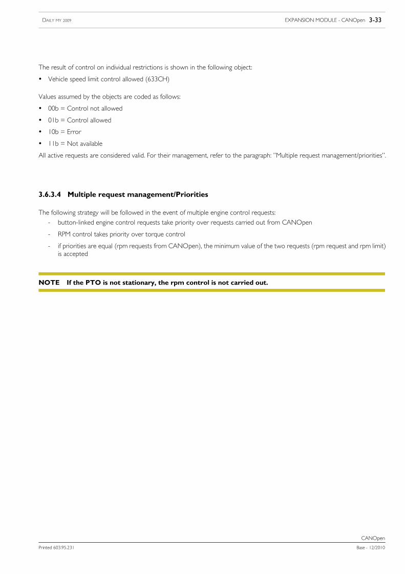
EXPANSION MODULE - CANOpen 3-33DAILY MY 2009
Printed 603.95.231 Base - 12/2010
CANOpen
The result of control on individual restrictions is shown in the following object:
• Vehicle speed limit control allowed (633CH)
Values assumed by the objects are coded as follows:
• 00b = Control not allowed
• 01b = Control allowed
• 10b = Error
• 11b = Not available
All active requests are considered valid. For their management, refer to the paragraph: ”Multiple request management/priorities”.
3.6.3.4 Multiple request management/Priorities
The following strategy will be followed in the event of multiple engine control requests:
- button-linked engine control requests take priority over requests carried out from CANOpen
- RPM control takes priority over torque control
- if priorities are equal (rpm requests from CANOpen), the minimum value of the two requests (rpm request and rpm limit)is accepted
If the PTO is not stationary, the rpm control is not carried out.NOTE

3-34 EXPANSION MODULE - CANOpen DAILY MY 2009
Base - 12/2010 Printed 603.95.231
CANOpen
3.7 Wiring diagram
For effective and correct use by Fitters, IVECO has arranged specific connection points to be used for the added systems.
Such points have been provided to rule out any additions to or adaptations of the basic design in order to ensure operational integrityand thus maintenance of the warranty.
3.7.1 Expansion Module Fitters sockets for CANOpen
The Expansion Module control unit pins for the CANOpen function are available through the Tyco 9-pin connector illustratedbelow:
Figure 4
126277
Tyco code8-968971-1
DescriptionCANOpen connector
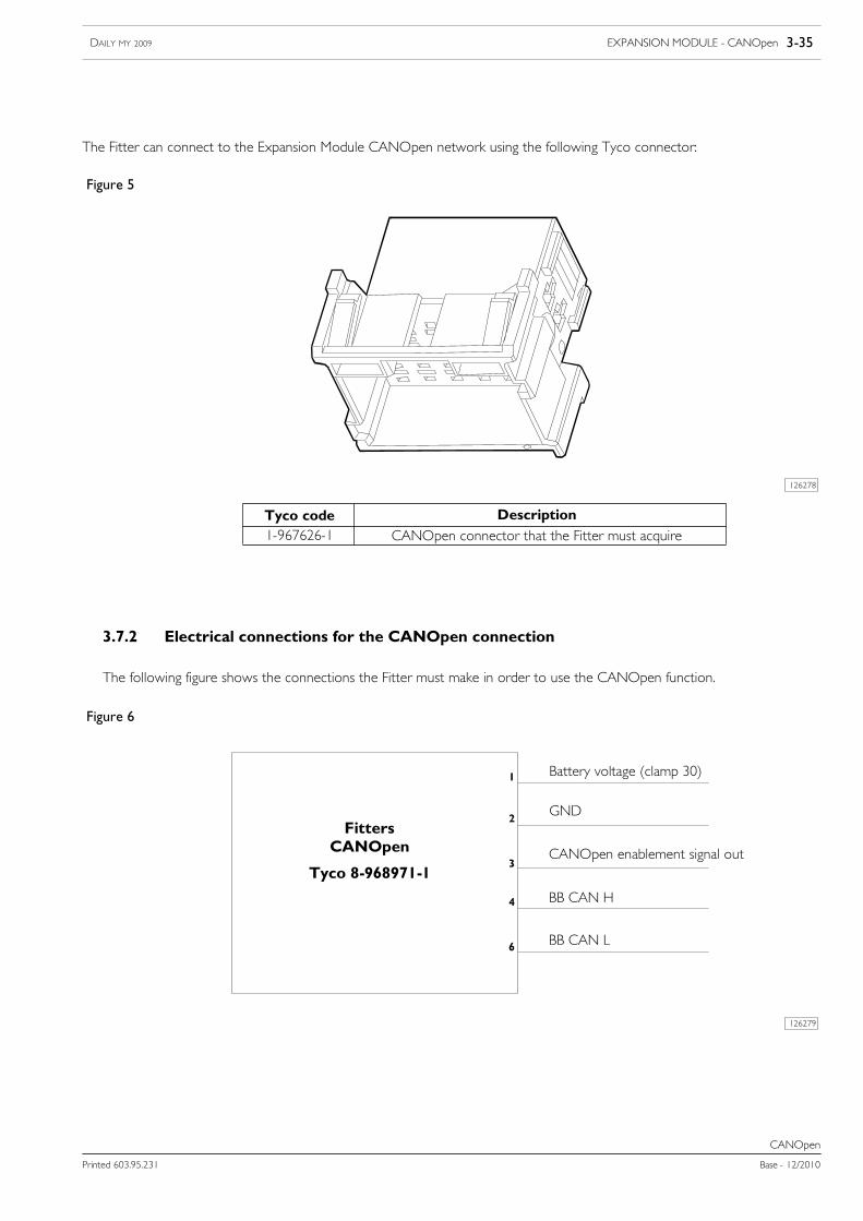
EXPANSION MODULE - CANOpen 3-35DAILY MY 2009
Printed 603.95.231 Base - 12/2010
CANOpen
The Fitter can connect to the Expansion Module CANOpen network using the following Tyco connector:
Figure 5
126278
Tyco code1-967626-1
DescriptionCANOpen connector that the Fitter must acquire
3.7.2 Electrical connections for the CANOpen connection
The following figure shows the connections the Fitter must make in order to use the CANOpen function.
Figure 6
126279
FittersCANOpen
Tyco 8-968971-1
Battery voltage (clamp 30)
CANOpen enablement signal out
GND
BB CAN H
BB CAN L

3-36 EXPANSION MODULE - CANOpen DAILY MY 2009
Base - 12/2010 Printed 603.95.231
CANOpen
Table 26
Pin Function Notes
1 VCC Battery voltage (clamp 30), protected by 10 A fuse
2 Earth Earth, max 10 A (not protected by fuse)
3 Enable Output signal (low active, max 200 mA) indicating whether the CANOpen network is enabled
4 BB_ CAN_H
5 CAN_GND
6 BB_ CAN_L
7 reserved
8 reserved
9 reserved
The CANOpen Enable pin need not necessarily be used. Refer to the following to understand the function.
The Fitter should fit the 120 Ohm termination resistance on their wiring for the CANOpen networkbetween BB_CAN_H and BB_CAN_L in order to allow communication between their control unitand the Expansion Module.
NOTE