Embed Size (px)
Citation preview
DAIKIN ROOM AIR CONDITIONER
INSTALLATION MANUALR410A Split Series
Eng
lish
Fran
çais
Esp
añol
MODELS
FTXS09LVJUFTXS12LVJUCTXS07LVJU
00_CV_3P297301-1.indd 1 10/18/2011 6:25:17 PM
Eng
lish
■English 1
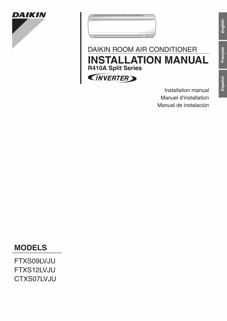
Safety Precautions•ReadtheseSafetyPrecautionscarefullytoensurecorrectinstallation.•ThismanualclassifiestheprecautionsintoDANGER,WARNINGandCAUTION.Besuretofollowalltheprecau-tionsbelow:theyareallimportantforensuringsafety.
DANGER ..........Indicates an imminently hazardous situation which, if not avoided, will result in death or serious injury.
WARNING ........Failure to follow any of WARNING is likely to result in such grave consequences as death or serious injury.
CAUTION .........Failure to follow any of CAUTION may in some cases result in grave consequences.
•Thefollowingsafetysymbolsareusedthroughoutthismanual:
Besuretoobservethisinstruction. Besuretoestablishagroundconnection. Neverattempt.
•Aftercompletinginstallation,testtheunittocheckforinstallationerrors.Givetheuseradequateinstructionscon-cerningtheuseandcleaningoftheunitaccordingtotheOperationManual.
DANGER•Refrigerantgasisheavierthanairandreplacesoxygen.Amassiveleakcouldleadtooxygendepletion,especiallyinbasements,andanasphyxiationhazardcouldoccurleadingtoseriousinjuryordeath.
•Iftherefrigerantgasleaksduringinstallation,ventilatetheareaimmediately.Refrigerantgasmayproduceatoxicgasifitcomesincontactwithfiresuchasfromafanheater,stoveorcookingdevice.Exposuretothisgascouldcausesevereinjuryordeath.
•Aftercompletingtheinstallationwork,checkthattherefrigerantgasdoesnotleak.Refrigerantgasmayproduceatoxicgasifitcomesincontactwithfiresuchasfromafanheater,stoveorcookingdevice.Exposuretothisgascouldcausesevereinjuryordeath.
•Donotgroundunitstowaterpipes,telephonewiresorlightningrodsbecauseincompletegroundingcouldcauseasevereshockhazardresultinginsevereinjuryordeath,andtogaspipesbecauseagasleakcouldresultinanexplosionwhichcouldleadtosevereinjuryordeath.
•Safelydisposeofthepackingmaterials.Packingmaterials,suchasnailsandothermetalorwoodenparts,maycausestabsorotherinjuries.Tearapartandthrowawayplasticpackagingbagssothatchildrenwillnotplaywiththem.Childrenplayingwithplasticbagsfacethedangerofdeathbysuffocation.
•Donotinstallunitinanareawhereflammablematerialsarepresentduetoriskofexplosionresultinginseriousinjuryordeath.•Donotgroundunitstotelephonewiresorlightningrodsbecauselightningstrikescouldcauseasevereshockhazardresultinginsevereinjuryordeath,andtogaspipesbecauseagasleakcouldresultinanexplosionwhichcouldleadtosevereinjuryordeath.
WARNING•Installationshallbelefttotheauthorizeddealeroranothertrainedprofessional.Improperinstallationmaycausewaterleakage,electricalshock,fire,orequipmentdamage.
•Installtheairconditioneraccordingtotheinstructionsgiveninthismanual.Incompleteinstallationmaycausewaterleakage,electricalshock,fireorequipmentdamage.
•Besuretousethesuppliedorexactspecifiedinstallationparts.Useofotherpartsmaycausetheunittocometofall,waterleakage,electricalshock,fireorequipmentdamage.
•Installtheairconditioneronasolidbasethatislevelandcansupporttheweightoftheunit.Aninadequatebaseorincompleteinstallationmaycauseinjuryorequipmentdamageintheeventtheunitfallsoffthebaseorcomesloose.
•Electricalworkshallbecarriedoutinaccordancewiththeinstallationmanualandthenational,stateandlocalelectricalwiringcodes.Insufficientcapacityorincompleteelectricalworkmaycauseelectricalshock,fireorequipmentdamage.
•Besuretouseadedicatedpowercircuit.Neveruseapowersupplysharedbyanotherappliance.Followallappropriateelectricalcodes.
•Forwiring,useawireorcablelongenoughtocovertheentiredistancewithnosplicesifpossible.Donotuseanextensioncord.Donotputotherloadsonthepowersupply.Useanonlyaseparatededicatedpowercircuit.(Failuretodosomaycauseabnormalheat,electricshock,fireorequipmentdamage.)
•Usethespecifiedtypesofwiresforelectricalconnectionsbetweentheindoorandoutdoorunits.Followallstateandlocalelectricalcodes.Firmlyclamptheinter-unitwiresotheirterminalsreceivenoexternalstresses.Incompleteconnectionsorclampingmaycauseterminaloverheating,fireorequipmentdamage.
•Afterconnectingallwiresbesuretoshapethecablessothattheydonotputunduestressontheelectricalcovers,panelsorterminals.Installcoversoverthewires.Incompletecoverinstallationmaycauseterminaloverheating,electricalshock,fireorequipmentdamage.
•Wheninstallingorrelocatingthesystem,besuretokeeptherefrigerantcircuitfreefromallsubstancesotherthanthespecifiedrefrigerant(R410A),suchasair.(Anypresenceofairorotherforeignsubstanceintherefrigerantcircuitcausesanabnormalpressurerisewhichmayresultinrupture,resultingininjury.)
01_EN_3P297301-1.indd 1 10/20/2011 2:38:21 PM

2 ■English
Safety Precautions WARNING
•Duringpump-down,stopthecompressorbeforeremovingtherefrigerantpiping.Ifthecompressorisstillrunningandthestopvalveisopenduringpump-down,airwillbesuckedinwhentherefrigerantpipingisremoved,causingabnormallyhighpressurewhichcouldleadtoequipmentdamageorandpersonalinjury.
•Duringinstallation,attachtherefrigerantpipingsecurelybeforerunningthecompressor.Iftherefrigerantpipesarenotattachedandthestopvalveisopenduringpump-down,airwillbesuckedinwhenthecompressorisrun,causingabnormallyhighpressurewhichcouldleadtoequipmentdamageandpersonalinjury.
•Besuretoinstallagroundfaultcircuitinterrupterbreaker.Failuretoinstallagroundfaultcircuitinterrupterbreakermayresultinelectricallyshocks,orfirepersonalinjury.
CAUTION•Donotinstalltheairconditionerwheregasleakagewouldbeexposedtoopenflames.Ifthegasleaksandbuildsuparoundtheunit,itmaycatchfire.
•Establishdrainpipingaccordingtotheinstructionsofthismanual.Inadequatepipingmaycausewaterdamage.•Tightentheflarenutaccordingtothespecifiedtorque.Atorquewrenchshouldbeused.Iftheflarenutistightenedtoomuch,theflarenutmaycrackovertimeandcauserefrigerantleakage.
•Donottouchtheheatexchangerfins.Improperhandlingmayresultininjury.
•Beverycarefulaboutproducttransportation.SomeproductsusePPbandsforpackaging.DonotuseanyPPbandsforameansoftransportation.Itisdangerous.
•ElectricalworkmustbeperformedinaccordancewiththeNEC/CECbyauthorizedpersonnelonly.
AccessoriesIndoor unit A – L ,
Mountingplate 1 Remotecontrollerholder 1 Tube 1
Mountingplatefixingscrew3/16”×1”(M4×25mm)
5 Fixingscrewforremotecontroller
holder1/8”×13/16”(M3×20mm)2 Operationmanual 1
Titaniumapatitephotocatalyticair-purifyingfilter
2 DrybatteryAAA.LR03
(alkaline)2 Installationmanual 1
Wirelessremotecontroller 1 Indoorunitfixingscrew
3/16”×1/2”(M4×12mm)2
Choosing an Installation Site•Beforechoosingtheinstallationsite,obtainuserapproval.
1. Indoor unit•Theindoorunitshouldbesitedinaplacewhere:1)therestrictionsoninstallationspecifiedintheindoorunitinstallationdrawingsaremet,2)bothairinletandairoutlethaveclearpathsmet,3)theunitisnotinthepathofdirectsunlight,4)theunitisawayfromthesourceofheatorsteam,5)thereisnosourceofmachineoilvapour(thismayshortenindoorunitlife),6)cool(warm)airiscirculatedthroughouttheroom,7)theunitisawayfromelectronicignitiontypefluorescentlamps(inverterorrapidstarttype)astheymayshortenthe
remotecontrollerrange,8)theunitisatleast3.5ft(1m)awayfromanytelevisionorradioset(unitmaycauseinterferencewiththepictureorsound),9)installattherecommendedheight6ft(1.8m),10)nolaundryequipmentislocatedinthespace.
2. Wireless remote controller1)Turnonallthefluorescentlampsintheroom,ifany,andfindthesitewhereremotecontrolsignalsareproperly
receivedbytheindoorunit(within23ft/7m).
A E J
B FK
C GL
DH
01_EN_3P297301-1.indd 2 10/20/2011 2:38:22 PM
Eng
lish
■English 3
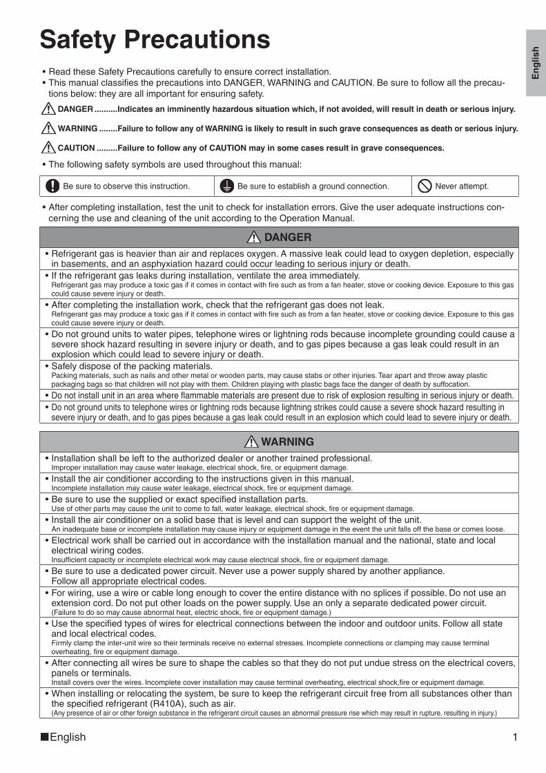
Indoor Unit Installation Drawings
Before screwing the remote controller holder to the wall, make sure that control signals are properly received by indoor unit.
E Remote controller holder
Fixing screw for remote controller holder 1/8” × 13/16” (M3 × 20mm)
F
D Wireless remote controller
Service lidOpening service lidService lid is opening/closing type.Opening method
1) Remove the service lid screw.2) Pull out the service lid diagonally
down in the direction of the arrow.3) Pull down.
1-3/16” (30mm) or more from ceiling
Front panel
1-15/16” (50mm)or more from walls(on both sides)
Titanium apatite photocatalytic air purifying filter (2 pcs)
A Mounting plate
C
Air filters
Mounting plate fixing screw 3/16” × 1” (M4 × 25mm)
B
3/16” × 5/8”(M4 × 16mm)
INTELLIGENT EYE sensor
Titanium apatite photocatalytic air-purifying filter
Filter frame
Air filterTab
Wrap the thermal insulation pipe with the finishing tape from bottom to top.
Cut thermal insulation pipe to an appropriate length and wrap it with tape, making sure that no gap is left in the insulation pipe’s cut line.
Caulk pipe hole gap with putty.
The mounting plate should be installed on a wall which can support the weight of the indoor unit.
How to attach the indoor unitHook the claws of the bottom frameto the mounting plate.If the claws are difficult to hook,remove the front grille.
How to remove the indoor unitPush up the marked area (at thelower part of the front grille) torelease the claws. If it is difficult torelease, remove the front grille.
Front grille
A Mountingplate
Clip
Bottom frame Mark (rear side)
INTELLIGENT EYE sensor
CAUTION•DonothitorforcefullypushtheINTELLIGENTEYEsensor.Thiscanleadtodamageandmalfunction.•Donotplacelargeobjectsnearthesensor.Alsokeepheatingunitsorhumidifiersoutsidethesensor’sdetectionarea.
01_EN_3P297301-1.indd 3 10/20/2011 2:38:22 PM
4 ■English
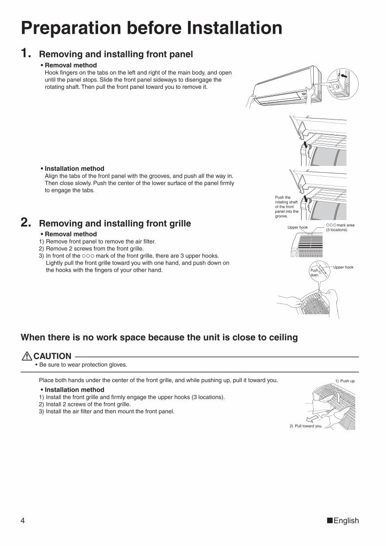
Preparation before Installation1. Removing and installing front panel
•Removal methodHookfingersonthetabsontheleftandrightofthemainbody,andopenuntilthepanelstops.Slidethefrontpanelsidewaystodisengagetherotatingshaft.Thenpullthefrontpaneltowardyoutoremoveit.
•Installation methodAlignthetabsofthefrontpanelwiththegrooves,andpushallthewayin.Thencloseslowly.Pushthecenterofthelowersurfaceofthepanelfirmlytoengagethetabs.
Push the rotating shaft of the front panel into the groove.
2. Removing and installing front grille•Removal method1)Removefrontpaneltoremovetheairfilter.2)Remove2screwsfromthefrontgrille.3)Infrontofthe markofthefrontgrille,thereare3upperhooks.
Lightlypullthefrontgrilletowardyouwithonehand,andpushdownonthehookswiththefingersofyourotherhand.
mark area (3 locations)
Upper hook
Pushdown.
Upper hook
When there is no work space because the unit is close to ceiling
CAUTION•Besuretowearprotectiongloves.
Placebothhandsunderthecenterofthefrontgrille,andwhilepushingup,pullittowardyou.
•Installation method1)Installthefrontgrilleandfirmlyengagetheupperhooks(3locations).2)Install2screwsofthefrontgrille.3)Installtheairfilterandthenmountthefrontpanel.
2) Pull toward you.
1) Push up.
01_EN_3P297301-1.indd 4 10/20/2011 2:38:23 PM
Eng
lish
■English 5
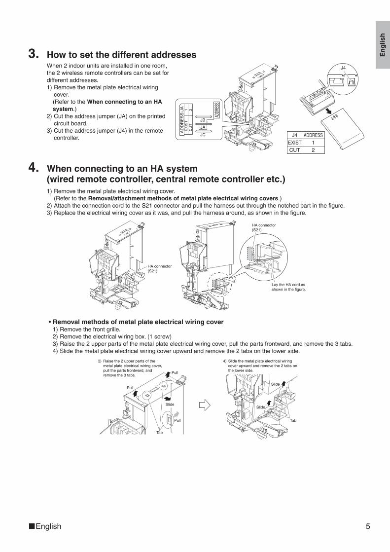
3. How to set the different addressesWhen2indoorunitsareinstalledinoneroom,the2wirelessremotecontrollerscanbesetfordifferentaddresses.1)Removethemetalplateelectricalwiring
cover.(RefertotheWhen connecting to an HA system.)
2)Cuttheaddressjumper(JA)ontheprintedcircuitboard.
3)Cuttheaddressjumper(J4)intheremotecontroller.
ADDR
ESS
JC
JA
JB
AD
DR
ES
S:J
AE
XIS
T1
CU
T2
J4 ADDRESSEXIST 1CUT 2
J4
4. When connecting to an HA system (wired remote controller, central remote controller etc.)1)Removethemetalplateelectricalwiringcover.
(RefertotheRemoval/attachment methods of metal plate electrical wiring covers.)2)AttachtheconnectioncordtotheS21connectorandpulltheharnessoutthroughthenotchedpartinthefigure.3)Replacetheelectricalwiringcoverasitwas,andpulltheharnessaround,asshowninthefigure.
HA connector(S21)
HA connector(S21)
Lay the HA cord as shown in the figure.
•Removal methods of metal plate electrical wiring cover1)Removethefrontgrille.2)Removetheelectricalwiringbox.(1screw)3)Raisethe2upperpartsofthemetalplateelectricalwiringcover,pullthepartsfrontward,andremovethe3tabs.4)Slidethemetalplateelectricalwiringcoverupwardandremovethe2tabsonthelowerside.
3) Raise the 2 upper parts of the metal plate electrical wiring cover, pull the parts frontward, and remove the 3 tabs.
4) Slide the metal plate electrical wiring cover upward and remove the 2 tabs on the lower side.
Tab
Slide
SlidePull
Pull
Slide
Pull
Tab
01_EN_3P297301-1.indd 5 10/20/2011 2:38:25 PM

6 ■English
Preparation before Installation•Attachment methods of metal plate electrical wiring coverAttachthemetalplateelectricalwiringcoverasshownbelow.1)Leanthemetalplateelectricalwiringcoverasshowninthefigureandattachtab(1)onthelowersidetotheelectrical
wiringbox.2)Attachtab(2)onthelowersideofthemetalplateelectricalwiringcover.
Tab (1)
Tab (2)
Tab (1)
3)Pushintheupperpartofthemetalplateelectricalwiringcoverandattachthe3tabs.
Tab
CAUTION• Make sure that the shaded part ( ) will
not go inside the electrical wiring box.
Refrigerant Piping WorkWith a multi indoor unit , install as described in the installation manual supplied with the Multi outdoor unit.
1. Flaring the pipe end 1)Cutthepipeendwithapipecutter.2)Removeburrswiththecutsurfacefacingdownward
sothatthechipsdonotenterthepipe.3)Puttheflarenutonthepipe.4)Flarethepipe.5)Checkthattheflaringisproperlymade.
Set exactly at the position shown below.
A
Flaring
Die A 0-0.020 inch (0-0.5mm)
Clutch-type
Flare tool for R410A
0.039-0.059 inch (1.0-1.5mm)
Clutch-type (Rigid-type)
0.059-0.079 inch (1.5-2.0mm)
Wing-nut type (Imperial-type)
Conventional flare tool
(Cut exactly at right angles.) Remove burrs.
Check
Flare’s inner surface must be flaw-free.
The pipe end must be evenly flared in a perfect circle.
Make sure that the flare nut is fitted.
WARNING•Donotusemineraloilonflaredpart.•Preventmineraloilfromgettingintothesystemasthiswouldreducethelifetimeoftheunits.•Neverusepipingwhichhasbeenusedforpreviousinstallations.Onlyusepartswhicharedeliveredwiththeunit.•NeverinstalladriertothisR410Aunitinordertoguaranteeitslifetime.•Thedryingmaterialmaydissolveanddamagethesystem.•Incompleteflaringmaycauserefrigerantgasleakage.
01_EN_3P297301-1.indd 6 10/20/2011 2:38:27 PM
Eng
lish
■English 7
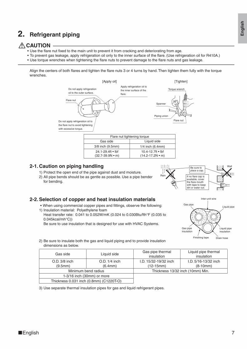
2. Refrigerant piping
CAUTION•Usetheflarenutfixedtothemainunittopreventitfromcrackinganddeterioratingfromage.•Topreventgasleakage,applyrefrigerationoilonlytotheinnersurfaceoftheflare.(UserefrigerationoilforR410A.)•Usetorquewrencheswhentighteningtheflarenutstopreventdamagetotheflarenutsandgasleakage.
Alignthecentersofbothflaresandtightentheflarenuts3or4turnsbyhand.Thentightenthemfullywiththetorquewrenches.
Do not apply refrigeration
oil to the outer surface.
Flare nut
Apply refrigeration oil to
the inner surface of the
flare.
Do not apply refrigeration oil to
the flare nut to avoid tightening
with excessive torque.
[Apply oil]
Torque wrench
Piping union
Flare nut
Spanner
[Tighten]
Flare nut tightening torqueGas side Liquid side
1/4 inch (6.4mm)
10.4-12.7ft • lbf(14.2-17.2N • m)
24.1-29.4ft • Ibf(32.7-39.9N • m)
3/8 inch (9.5mm)
2-1. Caution on piping handling 1)Protecttheopenendofthepipeagainstdustandmoisture.2)Allpipebendsshouldbeasgentleaspossible.Useapipebender
forbending.
Wall
If no flare cap is available, cover the flare mouth with tape to keep dirt or water out.
Be sure to place a cap.
Rain
2-2. Selection of copper and heat insulation materials•Whenusingcommercialcopperpipesandfittings,observethefollowing:1)Insulationmaterial:Polyethylenefoam
Heattransferrate:0.041to0.052W/mK(0.024to0.030Btu/fth°F(0.035to0.045kcal/mh°C))BesuretouseinsulationthatisdesignedforusewithHVACSystems.
Gas pipeLiquid pipe
Gas pipe insulation
Liquid pipe insulation
Finishing tape Drain hose
Inter-unit wire
2)Besuretoinsulateboththegasandliquidpipingandtoprovideinsulationdimensionsasbelow.
Gasside LiquidsideGaspipethermal
insulationLiquidpipethermal
insulationO.D.3/8inch(9.5mm)
O.D.1/4inch(6.4mm)
I.D.15/32-19/32inch(12-15mm)
I.D.5/16-13/32inch(8-10mm)
Minimumbendradius Thickness13/32inch(10mm)Min.1-3/16inch(30mm)ormore
Thickness0.031inch(0.8mm)(C1220T-O)
3)Useseparatethermalinsulationpipesforgasandliquidrefrigerantpipes.
01_EN_3P297301-1.indd 7 10/20/2011 2:38:28 PM
8 ■English
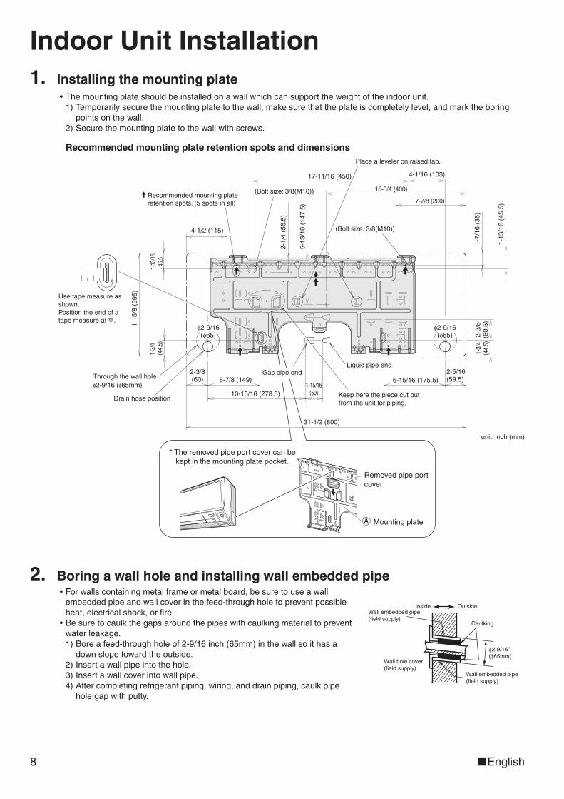
Indoor Unit Installation1. Installing the mounting plate
•Themountingplateshouldbeinstalledonawallwhichcansupporttheweightoftheindoorunit.1)Temporarilysecurethemountingplatetothewall,makesurethattheplateiscompletelylevel,andmarktheboring
pointsonthewall.2)Securethemountingplatetothewallwithscrews.
Recommended mounting plate retention spots and dimensions
unit: inch (mm)
Liquid pipe end
Drain hose position
Through the wall hole ϕ2-9/16 (ϕ65mm)
* The removed pipe port cover can be kept in the mounting plate pocket.
(Bolt size: 3/8(M10))
Recommended mounting plate retention spots. (5 spots in all)
(Bolt size: 3/8(M10))
1-3/
4 (4
4.5)
1-13
/16
45.5
11-5
/8 (
295)
4-1/2 (115)
2-1/
4 (5
6.5)
5-13
/16
(147
.5)
17-11/16 (450) 4-1/16 (103)
15-3/4 (400)
7-7/8 (200)
1-3/
4(4
4.5)
2-3/
8(6
0.5)
1-13
/16
(45.
5)
6-15/16 (175.5)
Keep here the piece cut out from the unit for piping.
2-5/16(59.5)
2-3/8(60) 5-7/8 (149)
10-15/16 (278.5)1-15/16
(50)
31-1/2 (800)
1-7/
16 (
36)
Removed pipe port cover
Mounting plate
Place a leveler on raised tab.
ϕ2-9/16(ϕ65)
A
Gas pipe end
Use tape measure as shown. Position the end of a tape measure at .
ϕ2-9/16(ϕ65)
2. Boring a wall hole and installing wall embedded pipe•Forwallscontainingmetalframeormetalboard,besuretouseawallembeddedpipeandwallcoverinthefeed-throughholetopreventpossibleheat,electricalshock,orfire.
•Besuretocaulkthegapsaroundthepipeswithcaulkingmaterialtopreventwaterleakage.1)Boreafeed-throughholeof2-9/16inch(65mm)inthewallsoithasa
downslopetowardtheoutside.2)Insertawallpipeintothehole.3)Insertawallcoverintowallpipe.4)Aftercompletingrefrigerantpiping,wiring,anddrainpiping,caulkpipe
holegapwithputty.
Inside Outside
Caulking
Wall embedded pipe (field supply)
Wall hole cover(field supply)
Wall embedded pipe (field supply)
ϕ2-9/16” (ϕ65mm)
01_EN_3P297301-1.indd 8 10/20/2011 2:38:29 PM

Eng
lish
■English 9
3. Laying piping, hoses, and wiring3-1. Right-side, right-back, or right-bottom piping
1)Attachthedrainhosetotheundersideoftherefrigerantpipeswithanadhesivevinyltape.
2)Wraptherefrigerantpipesanddrainhosetogetherwithinsulationtape.
Right-bottom piping
Right-side piping
Right-back piping
Bind refrigerant pipe and drain hose together with insulating tape.
Remove pipe port cover here for right-side piping.
Remove pipe port cover here for right-bottom piping.
3)Passthedrainhoseandrefrigerantpipesthroughthewallhole,thensettheindoorunitonthemountingplatehooksbyusingthe markingsatthetopoftheindoorunitasaguide.
Mounting plateA
3-2. Left-side, left-back, or left-bottom piping1)Replacethedrainpluganddrainhose.2)Attachthedrainhosetotheundersideoftherefrigerantpipes
withadhesivevinyltape.
Remove pipe port cover here for left-bottom piping.
Remove pipe port cover here for left-side piping.
Left-bottom piping
Left-side piping
Left-back piping
3)Besuretoconnectthedrainhosetothedrainportinplaceofadrainplug.
How to set drain plug.
No gap.Do not apply lubricating oil (refrigeration oil) when inserting.Application of causes deterioration and drain leakage of the plug.
Insert a hexagonal wrench 3/16” (4mm).
4)Shapetherefrigerantpipesalongthepipepathmarkingonthemountingplate.
5)Passdrainhoseandrefrigerantpipesthroughthewallhole,thensettheindoorunitonmountingplatehooks,usingthe markingsatthetopofindoorunitasaguide.
6)Pullintheinter-unitwire.7)Connecttheinter-unitpipes.
Drain hose
Caulk this hole with putty or caulking material. Bind with vinyl
tape.
A Mounting plate
Wrap insulating tape around the bent portion of refrigerant pipes. Overlap at least half the width of the tape with each turn.
8)Wraptherefrigerantpipesanddrainhosetogetherwithinsulationtapeasrightfigure,incaseofsettingthedrainhosethroughthebackoftheindoorunit.
9)Whileexercisingcaresothattheinter-unitwiredonotcatchindoorunit,pressthebottomedgeofindoorunitwithbothhandsuntilitisfirmlycaughtbythemountingplatehooks.Secureindoorunittothemountingplatewithindoorunitfixingscrews3/16×1/2inch(M4×12mm).
Refrigerantpipes
Drain hose
Bottom frameH Indoor unit fixing screw 3/16” × 1/2” (M4 × 12mm) (2 locations)
Mountingplate
AInter-unit wire
01_EN_3P297301-1.indd 9 10/20/2011 2:38:29 PM
10 ■English
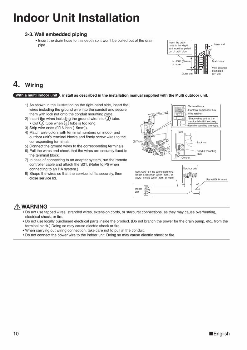
Indoor Unit Installation3-3. Wall embedded piping
•Insertthedrainhosetothisdepthsoitwon’tbepulledoutofthedrainpipe. Inner wall
Vinyl chloride drain pipe (VP-30)
Drain hose1-15/16” (50mm) or more
Insert the drain hose to this depth so it won’t be pulled out of drain pipe.
Outer wall
4. Wiring
With a multi indoor unit , install as described in the installation manual supplied with the Multi outdoor unit.
1)Asshownintheillustrationontheright-handside,insertthewiresincludingthegroundwireintotheconduitandsecurethemwithlocknutontotheconduitmountingplate.
2)Insertthewiresincludingthegroundwireintotube.•Cuttubewhentubeistoolong.
3)Stripwireends(9/16inch(15mm)).4)Matchwirecolorswithterminalnumbersonindoorand
outdoorunit’sterminalblocksandfirmlyscrewwirestothecorrespondingterminals.
5)Connectthegroundwirestothecorrespondingterminals.6)Pullthewiresandcheckthatthewiresaresecurelyfixedto
theterminalblock.7)Incaseofconnectingtoanadaptersystem,runtheremote
controllercableandattachtheS21.(RefertoP5whenconnectingtoanHAsystem.)
8)Shapethewiressothattheservicelidfitssecurely,thencloseservicelid.
123
1 2 3 GRL1L2Use AWG16 if the connection wire length is less than 32.8ft (10m), or AWG14 if it is 32.8ft (10m) or more.
Outdoor unit
Indoor unit
Use AWG 14 wires.
Conduit mounting plate
Lock nut
Back
Conduit
Terminal block
Electrical component box
Use the specified wire type.
Wire retainer
Shape wires so that the service lid will fit securely.
TubeJ
WARNING•Donotusetappedwires,strandedwires,extensioncords,orstarburstconnections,astheymaycauseoverheating,electricalshock,orfire.
•Donotuselocallypurchasedelectricalpartsinsidetheproduct.(Donotbranchthepowerforthedrainpump,etc.,fromtheterminalblock.)Doingsomaycauseelectricshockorfire.
•Whencarryingoutwiringconnection,takecarenottopullattheconduit.•Donotconnectthepowerwiretotheindoorunit.Doingsomaycauseelectricshockorfire.
JJ J
01_EN_3P297301-1.indd 10 10/20/2011 2:38:30 PM
Eng
lish
■English 11
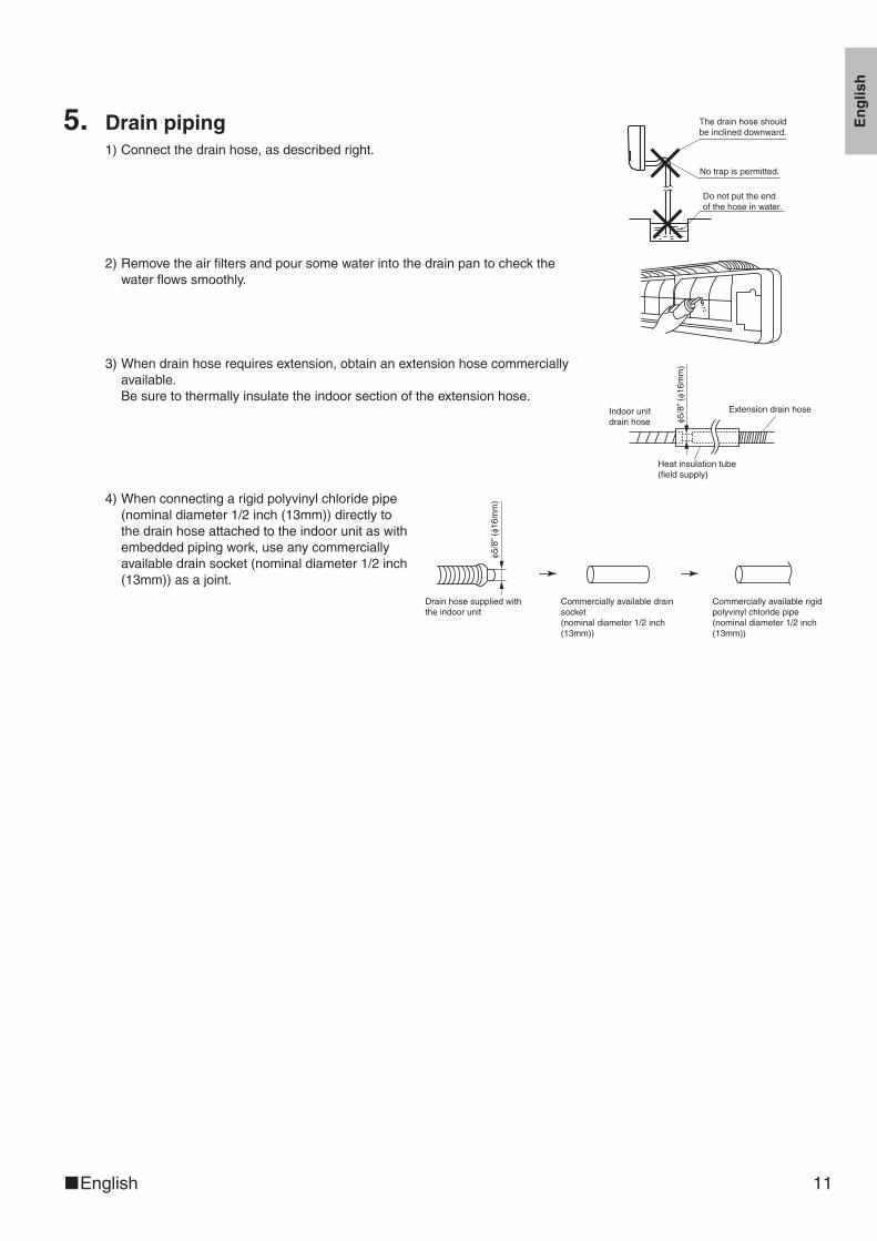
5. Drain piping1)Connectthedrainhose,asdescribedright.
The drain hose should be inclined downward.
No trap is permitted.
Do not put the end of the hose in water.
2)Removetheairfiltersandpoursomewaterintothedrainpantocheckthewaterflowssmoothly.
3)Whendrainhoserequiresextension,obtainanextensionhosecommerciallyavailable.Besuretothermallyinsulatetheindoorsectionoftheextensionhose.
Indoor unit drain hose ϕ5
/8” (ϕ1
6mm
)
Extension drain hose
Heat insulation tube(field supply)
4)Whenconnectingarigidpolyvinylchloridepipe(nominaldiameter1/2inch(13mm))directlytothedrainhoseattachedtotheindoorunitaswithembeddedpipingwork,useanycommerciallyavailabledrainsocket(nominaldiameter1/2inch(13mm))asajoint.
Drain hose supplied with the indoor unit
Commercially available drain socket (nominal diameter 1/2 inch (13mm))
Commercially available rigid polyvinyl chloride pipe(nominal diameter 1/2 inch (13mm))
ϕ5/8
” (ϕ1
6mm
)
01_EN_3P297301-1.indd 11 10/20/2011 2:38:30 PM
12 ■English
Trial Operation and Testing1. Trial operation and testing
1-1 Measurethesupplyvoltageandmakesurethatitfallsinthespecifiedrange.
1-2 Trialoperationshouldbecarriedoutineithercoolingorheatingmode.
•Incoolingmode,selectthelowestprogrammabletemperature;inheatingmode,selectthehighestprogrammabletemperature.1)Trialoperationmaybedisabledineithermodedependingontheroomtemperature.
Usetheremotecontrollerfortrialoperationasdescribedbelow.2)Aftertrialoperationiscomplete,setthetemperaturetoanormallevel(78°Fto82°F(26°Cto28°C)incoolingmode,
68°Fto75°F(20°Cto24°C)inheatingmode).3)Forprotection,thesystemdisablesrestartoperationfor3minutesafteritisturnedoff.
1-3 Carryoutthetestoperationinaccordancewiththeoperationmanualtoensurethatallfunctionsandparts,suchasfinmovement,areworkingproperly.•Theairconditionerrequiresasmallamountofpowerinitsstandbymode.Ifthesystemisnottobeusedforsometimeafterinstallation,shutoffthecircuitbreakertoeliminateunnecessarypowerconsumption.
•Ifthecircuitbreakertripstoshutoffthepowertotheairconditioner,thesystemwillrestoretheoriginaloperationmodewhenthecircuitbreakerisopenedagain.
Trial operation from remote controller1)Press“ON/OFF”buttontoturnonthesystem.2)Press“TEMP”button(2locations)and“MODE”buttonatthesametime.3)Press“MODE”buttontwice.
(“T”willappearonthedisplaytoindicatethattrialoperationmodeisselected.)4)Trialoperationterminatesinapprox.30minutesandswitchesintonormalmode.Toquitatrialoperation,press“ON/
OFF”button.
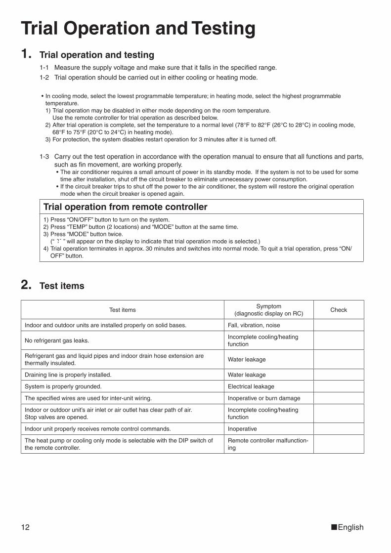
2. Test items
TestitemsSymptom
(diagnosticdisplayonRC)Check
Indoorandoutdoorunitsareinstalledproperlyonsolidbases. Fall,vibration,noise
Norefrigerantgasleaks.Incompletecooling/heatingfunction
Refrigerantgasandliquidpipesandindoordrainhoseextensionarethermallyinsulated.
Waterleakage
Draininglineisproperlyinstalled. Waterleakage
Systemisproperlygrounded. Electricalleakage
Thespecifiedwiresareusedforinter-unitwiring. Inoperativeorburndamage
Indoororoutdoorunit’sairinletorairoutlethasclearpathofair.Stopvalvesareopened.
Incompletecooling/heatingfunction
Indoorunitproperlyreceivesremotecontrolcommands. Inoperative
TheheatpumporcoolingonlymodeisselectablewiththeDIPswitchoftheremotecontroller.
Remotecontrollermalfunction-ing
01_EN_3P297301-1.indd 12 10/20/2011 2:38:30 PM
Two-dimensional bar code is a code for manufacturing.
3P297301-1 M11B119 (1111) HT
00_CV_3P297301-1.indd 2 10/18/2011 6:25:17 PM