Embed Size (px)
Citation preview
D-1
D
VAN
E P
UM
PS
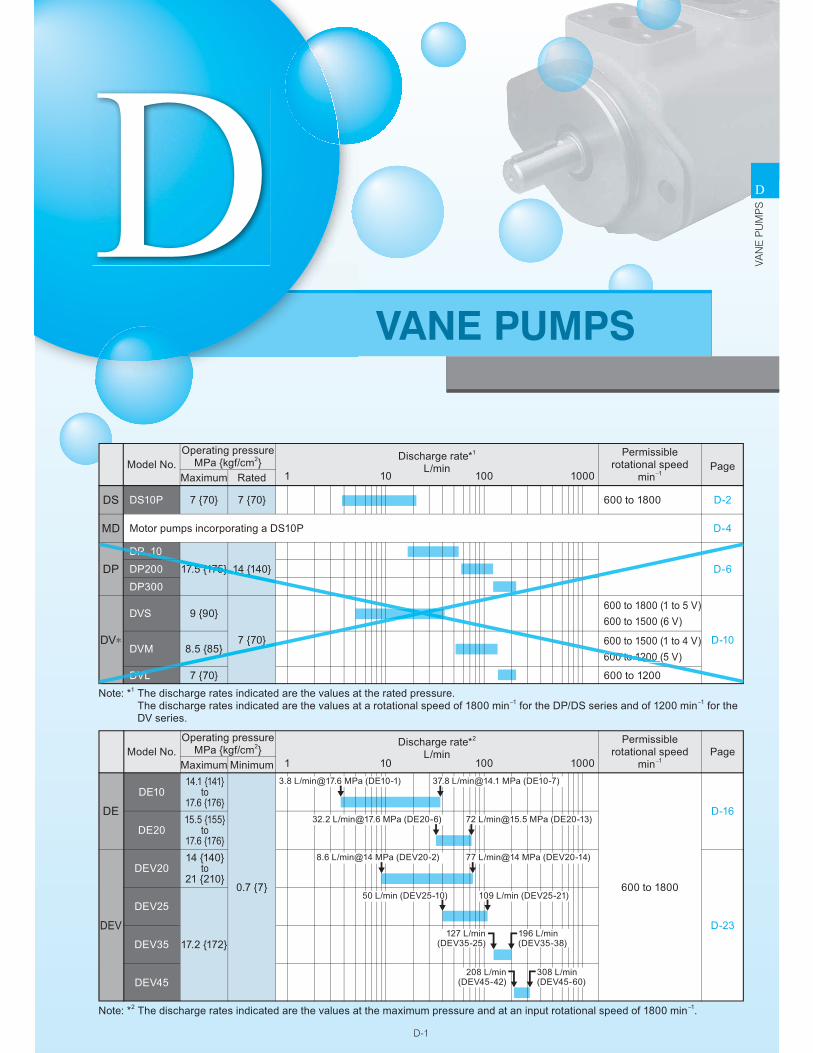
Model No.Discharge rate*1
L/minPermissible
rotational speedmin−11
DP 10
17.5 {175} 14 {140}DP200
DP300
DVS
DVM
DVL
DP
10 100 1000
DV∗
9 {90}
7 {70}8.5 {85}
7 {70}
600 to 1800 (1 to 5 V)600 to 1500 (6 V)
600 to 1500 (1 to 4 V)600 to 1200 (5 V)
600 to 1200
Note: *1 The discharge rates indicated are the values at the rated pressure.The discharge rates indicated are the values at a rotational speed of 1800 min−1 for the DP/DS series and of 1200 min−1 for the DV series.
D-6
D-10
Page
DS10PDS 7 {70} 7 {70} 600 to 1800 D-2
Motor pumps incorporating a DS10PMD D-4
Operating pressureMPa {kgf/cm2}
Maximum Rated
Model No.Discharge rate*2
L/minPermissible
rotational speedmin−1
Note: *2 The discharge rates indicated are the values at the maximum pressure and at an input rotational speed of 1800 min−1.
PageOperating pressure
MPa {kgf/cm2}Maximum Minimum
DE10
DE20
DEV20
DEV25
DEV35
DEV45
14.1 {141} to
17.6 {176}DE
DEV
15.5 {155} to
17.6 {176}
0.7 {7}
17.2 {172}
600 to 1800
D-16
D-23
14 {140} to
21 {210}
1 10 100 10003.8 L/[email protected] MPa (DE10-1) 37.8 L/[email protected] MPa (DE10-7)
32.2 L/[email protected] MPa (DE20-6) 72 L/[email protected] MPa (DE20-13)
8.6 L/min@14 MPa (DEV20-2) 77 L/min@14 MPa (DEV20-14)
50 L/min (DEV25-10) 109 L/min (DEV25-21)
127 L/min(DEV35-25)
196 L/min(DEV35-38)
208 L/min(DEV45-42)
308 L/min(DEV45-60)
DVANE PUMPS
600 to 1200 (
DP 10
7.5 {175} 14 {1
DVL
}}
D-2
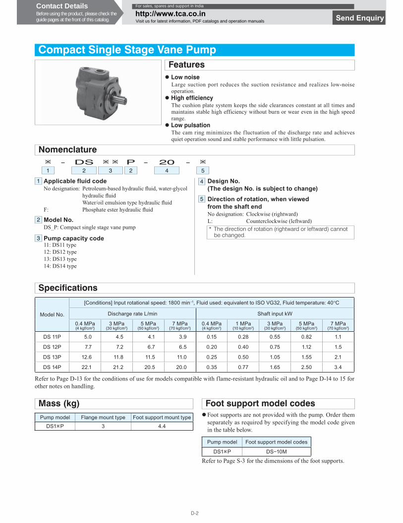
Compact Single Stage Vane PumpFeatures� Low noise
Large suction port reduces the suction resistance and realizes low-noise operation.
� High efficiencyThe cushion plate system keeps the side clearances constant at all times and maintains stable high efficiency without burn or wear even in the high speed range.
� Low pulsationThe cam ring minimizes the fluctuation of the discharge rate and achieves quiet operation sound and stable performance with little pulsation.
Applicable fluid codeNo designation: Petroleum-based hydraulic � uid, water-glycol
hydraulic � uidWater/oil emulsion type hydraulic � uid
F: Phosphate ester hydraulic � uid
Model No.DS_P: Compact single stage vane pump
Pump capacity code11: DS11 type12: DS12 type13: DS13 type14: DS14 type
Design No. (The design No. is subject to change)Direction of rotation, when viewed from the shaft endNo designation: Clockwise (rightward)L: Counterclockwise (leftward)
Nomenclature� - DS � � P - 20 - �1 2 3 2 4 5
* The direction of rotation (rightward or leftward) cannot be changed.
Specifications
Model No.
[Conditions] Input rotational speed: 1800 min−1, Fluid used: equivalent to ISO VG32, Fluid temperature: 40°C
Discharge rate L/min Shaft input kW
0.4 MPa{4 kgf/cm2}
3 MPa{30 kgf/cm2}
5 MPa{50 kgf/cm2}
7 MPa{70 kgf/cm2}
0.4 MPa{4 kgf/cm2}
1 MPa{10 kgf/cm2}
3 MPa{30 kgf/cm2}
5 MPa{50 kgf/cm2}
7 MPa{70 kgf/cm2}
DS 11P 5.0 4.5 4.1 3.9 0.15 0.28 0.55 0.82 1.1
DS 12P 7.7 7.2 6.7 6.5 0.20 0.40 0.75 1.12 1.5
DS 13P 12.6 11.8 11.5 11.0 0.25 0.50 1.05 1.55 2.1
DS 14P 22.1 21.2 20.5 20.0 0.35 0.77 1.65 2.50 3.4
Mass (kg)Pump model Flange mount type Foot support mount type
DS1�P 3 4.4
Refer to Page D-13 for the conditions of use for models compatible with flame-resistant hydraulic oil and to Page D-14 to 15 for other notes on handling.
Foot support model codes
Pump model Foot support model codes
DS1�P DS�10M
� Foot supports are not provided with the pump. Order them separately as required by specifying the model code given in the table below.
Refer to Page S-3 for the dimensions of the foot supports.
1
2
5
4
3
Contact DetailsBefore using the product, please check theguide pages at the front of this catalog.
For sales, spares and support in India
http://www.tca.co.inVisit us for latest information, PDF catalogs and operation manuals Send Enquiry
D-4
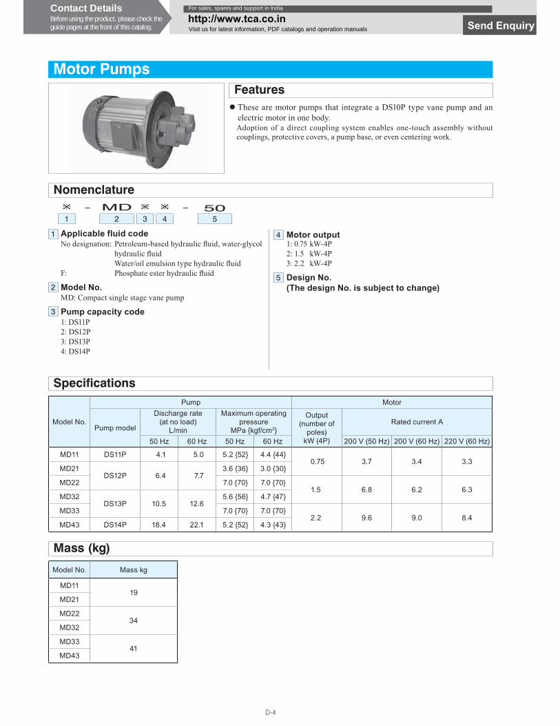
Motor PumpsFeatures� These are motor pumps that integrate a DS10P type vane pump and an
electric motor in one body.Adoption of a direct coupling system enables one-touch assembly without couplings, protective covers, a pump base, or even centering work.
Applicable fluid codeNo designation: Petroleum-based hydraulic � uid, water-glycol
hydraulic � uidWater/oil emulsion type hydraulic � uid
F: Phosphate ester hydraulic � uid
Model No.MD: Compact single stage vane pump
Pump capacity code1: DS11P2: DS12P3: DS13P4: DS14P
Motor output1: 0.75 kW-4P2: 1.5 kW-4P3: 2.2 kW-4P
Design No. (The design No. is subject to change)
Nomenclature� - MD � � - 501 2 3 4 5
Specifications
Model No.
Pump Motor
Pump model
Discharge rate (at no load)
L/min
Maximum operating pressure
MPa {kgf/cm2}
Output (number of
poles)kW (4P)
Rated current A
50 Hz 60 Hz 50 Hz 60 Hz 200 V (50 Hz) 200 V (60 Hz) 220 V (60 Hz)
MD11 DS11P 4.1 5.0 5.2 {52} 4.4 {44}0.75 3.7 3.4 3.3
MD21DS12P 6.4 7.7
3.6 {36} 3.0 {30}
MD22 7.0 {70} 7.0 {70}1.5 6.8 6.2 6.3
MD32DS13P 10.5 12.6
5.6 {56} 4.7 {47}
MD33 7.0 {70} 7.0 {70}2.2 9.6 9.0 8.4
MD43 DS14P 18.4 22.1 5.2 {52} 4.3 {43}
Mass (kg)
Model No. Mass kg
MD1119
MD21
MD2234
MD32
MD3341
MD43
1
25
4
3
Contact DetailsBefore using the product, please check theguide pages at the front of this catalog.
For sales, spares and support in India
http://www.tca.co.inVisit us for latest information, PDF catalogs and operation manuals Send Enquiry
D-16
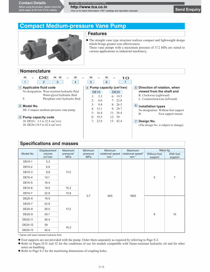
Compact Medium-pressure Vane PumpFeatures� The straight vane type structure realizes compact and lightweight design
which brings greater cost effectiveness.These vane pumps with a maximum pressure of 17.2 MPa are suited to various applications in industrial machinery.
Applicable fluid codeNo designation: Wear-resistant hydraulic � uid
Water-glycol hydraulic � uidF: Phosphate ester hydraulic � uid
Model No.DE: Compact medium-pressure vane pump
Pump capacity code10: DE10 ( 3.3 to 22.8 cm3/rev)20: DE20 ( 19.5 to 42.4 cm3/rev)
Pump capacity (cm3/rev)DE10 DE201: 3.3 6: 19.52: 6.6 7: 22.83: 9.8 8: 26.54: 13.1 9: 29.75: 16.4 11: 36.46: 19.5 12: 397: 22.8 13: 42.4
Nomenclature� - DE � � - � - � - � - 101 2 3 4 5 6 7
Specifications and masses
Model No.Displacement
volumecm3/rev
Maximum pressure*
MPa
Minimum pressure
MPa
Minimum rotational speed
min−1
Maximum rotational speed*
min−1
Mass kgWithout foot
supportWith foot support
DE10-1 3.3
17.2
0.7 600 1800
5 7
DE10-2 6.6
DE10-3 9.8
DE10-4 13.1
DE10-5 16.4
DE10-6 19.5 15.2
DE10-7 22.8 13.8
DE20-6 19.5
17.2
8 10
DE20-7 22.8
DE20-8 26.5
DE20-9 29.7
DE20-11 36.4
DE20-12 3915.2
DE20-13 42.4
Direction of rotation, when viewed from the shaft endR: Clockwise (rightward)L: Counterclockwise (leftward)
Installation typesNo designation: Without foot supportB: Foot support mount
Design No.(The design No. is subject to change)
� Foot supports are not provided with the pump. Order them separately as required by referring to Page S-2.� Refer to Pages D-31 and 32 for the conditions of use for models compatible with flame-resistant hydraulic oil and for other
notes on handling.� Refer to Page S-3 for the machining dimensions of coupling holes.
* Values with wear-resistant hydraulic � uid
1
2
3
4
6
7
5
Contact DetailsBefore using the product, please check theguide pages at the front of this catalog.
For sales, spares and support in India
http://www.tca.co.inVisit us for latest information, PDF catalogs and operation manuals Send Enquiry
D-18
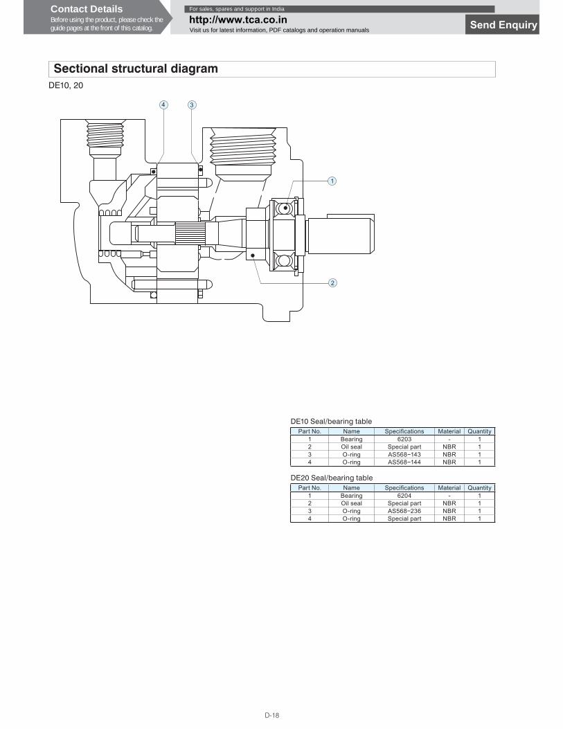
Sectional structural diagramDE10, 20
Part No. Name Speci� cations Material Quantity1 Bearing 6203 - 12 Oil seal Special part NBR 13 O-ring AS568�143 NBR 14 O-ring AS568�144 NBR 1
DE10 Seal/bearing table
1
3
2
4
Part No. Name Speci� cations Material Quantity1 Bearing 6204 - 12 Oil seal Special part NBR 13 O-ring AS568�236 NBR 14 O-ring Special part NBR 1
DE20 Seal/bearing table
Contact DetailsBefore using the product, please check theguide pages at the front of this catalog.
For sales, spares and support in India
http://www.tca.co.inVisit us for latest information, PDF catalogs and operation manuals
Send Enquiry
D-19
D
VAN
E P
UM
PS
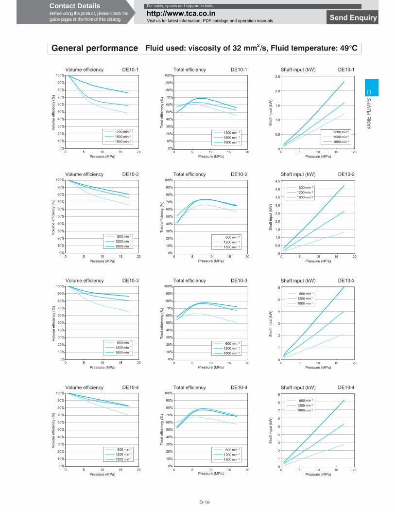
General performance Fluid used: viscosity of 32 mm2/s, Fluid temperature: 49°C
120015001800
Pressure (MPa)
Volume efficiency
Vol
ume
effic
ienc
y (%
)
100%
90%
80%
70%
60%
50%
40%
30%
20%
10%
0%0 5
DE10-1
10 15 20
100%
90%
80%
70%
60%
50%
40%
30%
20%
10%
0%0 5
DE10-1
10 15 20
120015001800
Pressure (MPa)
Total efficiency
Tota
l effi
cien
cy (%
)
2.5
2.0
1.5
1.0
0.5
00 5
Pressure (MPa)
Shaft input (kW) DE10-1
Sha
ft in
put (
kW)
10 15 20
120015001800
0 5
DE10-2
10 15 20
60012001800
Pressure (MPa)
Volume efficiency
Vol
ume
effic
ienc
y (%
)
100%
90%
80%
70%
60%
50%
40%
30%
20%
10%
0%0 5
DE10-2
10 15 20
60012001800
100%
90%
80%
70%
60%
50%
40%
30%
20%
10%
0%
Pressure (MPa)
Total efficiency
Tota
l effi
cien
cy (%
)
4.5
4.0
3.5
3.0
2.5
1.5
2.0
0.5
1.0
00 5
DE10-2
10 15 20
60012001800
Pressure (MPa)
Shaft input (kW)
Sha
ft in
put (
kW)
0 5
DE10-3
10 15 20
60012001800
Pressure (MPa)
Volume efficiency
Vol
ume
effic
ienc
y (%
)
100%
90%
80%
70%
60%
50%
40%
30%
20%
10%
0%0 5
DE10-3
10 15 20
60012001800
100%
90%
80%
70%
60%
50%
40%
30%
20%
10%
0%
Pressure (MPa)
Total efficiency
Tota
l effi
cien
cy (%
)
6
5
4
3
2
1
00 5
DE10-3
10 15 20
60012001800
Pressure (MPa)
Shaft input (kW)
Sha
ft in
put (
kW)
0 5
DE10-4
10 15 20
60012001800
Pressure (MPa)
Volume efficiency
Vol
ume
effic
ienc
y (%
)
100%
90%
80%
70%
60%
50%
40%
30%
20%
10%
0%0 5
DE10-4
10 15 20
60012001800
100%
90%
80%
70%
60%
50%
40%
30%
20%
10%
0%
Pressure (MPa)
Total efficiency
Tota
l effi
cien
cy (%
)
9
8
7
6
5
3
4
1
2
00 5
DE10-4
10 15 20
60012001800
Pressure (MPa)
Shaft input (kW)
Sha
ft in
put (
kW)
Contact DetailsBefore using the product, please check theguide pages at the front of this catalog.
For sales, spares and support in India
http://www.tca.co.inVisit us for latest information, PDF catalogs and operation manuals Send Enquiry
D-20
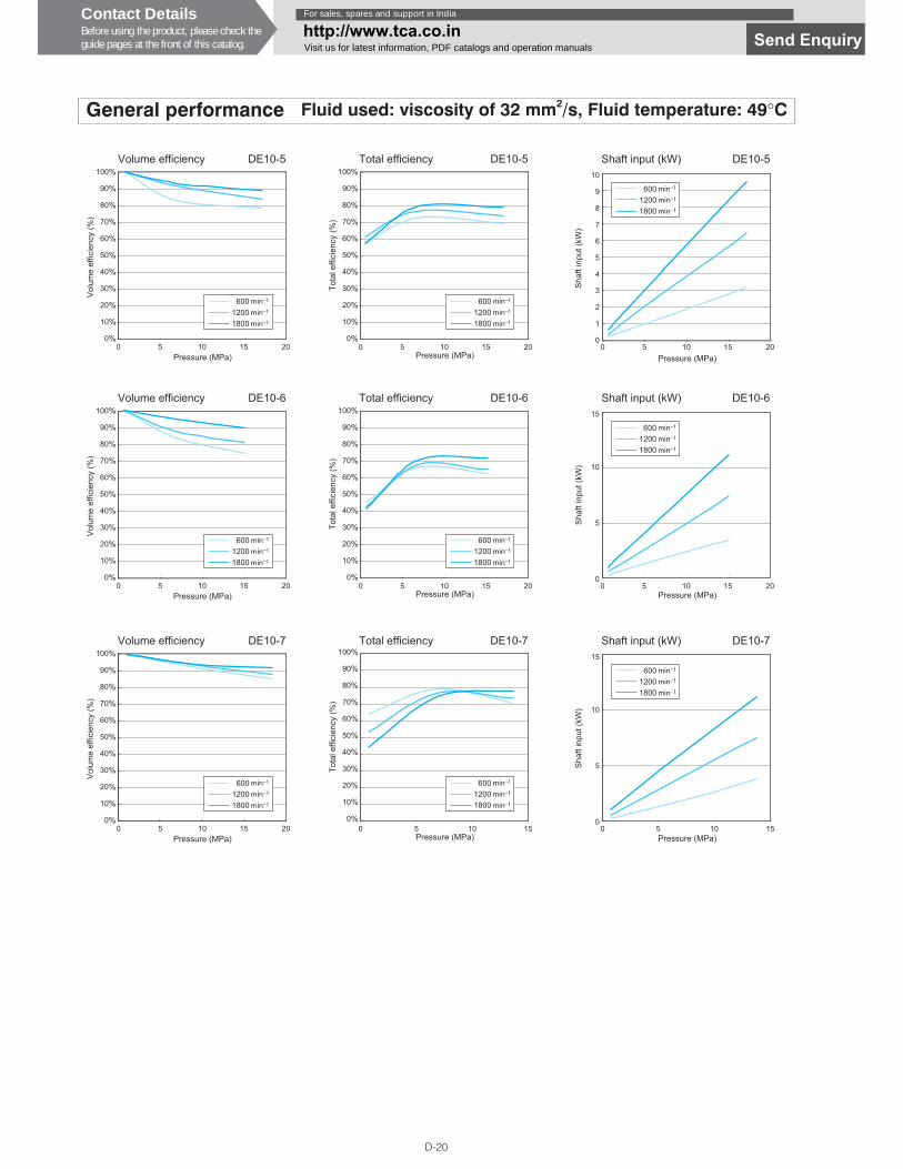
General performance Fluid used: viscosity of 32 mm2/s, Fluid temperature: 49°C
0 5
DE10-5
10 15 20
60012001800
Pressure (MPa)
Volume efficiency
Vol
ume
effic
ienc
y (%
)
100%
90%
80%
70%
60%
50%
40%
30%
20%
10%
0%0 5
DE10-5
10 15 20
60012001800
100%
90%
80%
70%
60%
50%
40%
30%
20%
10%
0%
Pressure (MPa)
Total efficiency
Tota
l effi
cien
cy (%
)
10
9
8
7
6
4
5
1
2
3
00 5
DE10-5
10 15 20
60012001800
Pressure (MPa)
Shaft input (kW)
Sha
ft in
put (
kW)
0 5
DE10-6
10 15 20
60012001800
Pressure (MPa)
Volume efficiency
Vol
ume
effic
ienc
y (%
)
100%
90%
80%
70%
60%
50%
40%
30%
20%
10%
0%0 5
DE10-6
10 15 20
60012001800
100%
90%
80%
70%
60%
50%
40%
30%
20%
10%
0%
Pressure (MPa)
Total efficiency
Tota
l effi
cien
cy (%
)
15
10
5
00 5
DE10-6
10 15 20
60012001800
Pressure (MPa)
Shaft input (kW)
Sha
ft in
put (
kW)
0 5
DE10-7
10 15 20
60012001800
Pressure (MPa)
Volume efficiency
Vol
ume
effic
ienc
y (%
)
100%
90%
80%
70%
60%
50%
40%
30%
20%
10%
0%0 5
DE10-7
10 15
60012001800
100%
90%
80%
70%
60%
50%
40%
30%
20%
10%
0%
Pressure (MPa)
Total efficiency
Tota
l effi
cien
cy (%
)
15
10
5
00 5
DE10-7
10 15
60012001800
Pressure (MPa)
Shaft input (kW)
Sha
ft in
put (
kW)
Contact DetailsBefore using the product, please check theguide pages at the front of this catalog.
For sales, spares and support in India
http://www.tca.co.inVisit us for latest information, PDF catalogs and operation manuals
Send Enquiry

D-21
D
VAN
E P
UM
PS
General performance Fluid used: viscosity of 32 mm2/s, Fluid temperature: 49°C
60012001800
0 5
DE20-6
10 15 20Pressure (MPa)
Volume efficiency
Vol
ume
effic
ienc
y (%
)
100%
90%
80%
70%
60%
50%
40%
30%
20%
10%
0%
60012001800
0 5
DE20-6
10 15 20
100%
90%
80%
70%
60%
50%
40%
30%
20%
10%
0%
Pressure (MPa)
Total efficiency
Tota
l effi
cien
cy (%
)
15
10
5
00 5
DE20-6
10 15 20
60012001800
Pressure (MPa)
Shaft input (kW)
Sha
ft in
put (
kW)
60012001800
0 5
DE20-7
10 15 20Pressure (MPa)
Volume efficiency
Vol
ume
effic
ienc
y (%
)
100%
90%
80%
70%
60%
50%
40%
30%
20%
10%
0%
60012001800
0 5
DE20-7
10 15 20
100%
90%
80%
70%
60%
50%
40%
30%
20%
10%
0%
Pressure (MPa)
Total efficiency
Tota
l effi
cien
cy (%
)
15
10
5
00 5
DE20-7
10 15 20
60012001800
Pressure (MPa)
Shaft input (kW)
Sha
ft in
put (
kW)
60012001800
0 5
DE20-8
10 15 20Pressure (MPa)
Volume efficiency
Vol
ume
effic
ienc
y (%
)
100%
90%
80%
70%
60%
50%
40%
30%
20%
10%
0%
60012001800
0 5
DE20-8
10 15 20
100%
90%
80%
70%
60%
50%
40%
30%
20%
10%
0%
Pressure (MPa)
Total efficiency
Tota
l effi
cien
cy (%
)
20
15
10
5
00 5
DE20-8
10 15 20
60012001800
Pressure (MPa)
Shaft input (kW)
Sha
ft in
put (
kW)
60012001800
0 5
DE20-9
10 15 20Pressure (MPa)
Volume efficiency
Vol
ume
effic
ienc
y (%
)
100%
90%
80%
70%
60%
50%
40%
30%
20%
10%
0%
60012001800
0 5
DE20-9
10 15 20
100%
90%
80%
70%
60%
50%
40%
30%
20%
10%
0%
Pressure (MPa)
Total efficiency
Tota
l effi
cien
cy (%
)
20
15
10
5
00 5
DE20-9
10 15 20
60012001800
Pressure (MPa)
Shaft input (kW)
Sha
ft in
put (
kW)
Contact DetailsBefore using the product, please check theguide pages at the front of this catalog.
For sales, spares and support in India
http://www.tca.co.inVisit us for latest information, PDF catalogs and operation manuals Send Enquiry
D-22
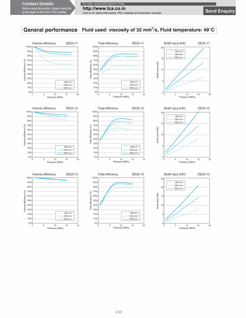
General performance Fluid used: viscosity of 32 mm2/s, Fluid temperature: 49°C
60012001800
0 5
DE20-11
10 15 20Pressure (MPa)
Volume efficiency
Vol
ume
effic
ienc
y (%
)
100%
90%
80%
70%
60%
50%
40%
30%
20%
10%
0%
60012001800
0 5
DE20-11
10 15 20
100%
90%
80%
70%
60%
50%
40%
30%
20%
10%
0%
Pressure (MPa)
Total efficiency
Tota
l effi
cien
cy (%
)
20
15
10
5
00 5
DE20-11
10 15 20
60012001800
Pressure (MPa)
Shaft input (kW)
Sha
ft in
put (
kW)
60012001800
0 5
DE20-12
10 15 20Pressure (MPa)
Volume efficiency
Vol
ume
effic
ienc
y (%
)
100%
90%
80%
70%
60%
50%
40%
30%
20%
10%
0%
60012001800
0 5
DE20-12
10 15 20
100%
90%
80%
70%
60%
50%
40%
30%
20%
10%
0%
Pressure (MPa)
Total efficiency
Tota
l effi
cien
cy (%
)
20
15
10
5
00 5
DE20-12
10 15 20
60012001800
Pressure (MPa)
Shaft input (kW)
Sha
ft in
put (
kW)
60012001800
0 5
DE20-13
10 15 20Pressure (MPa)
Volume efficiency
Vol
ume
effic
ienc
y (%
)
100%
90%
80%
70%
60%
50%
40%
30%
20%
10%
0%
60012001800
0 5
DE20-13
10 15 20
100%
90%
80%
70%
60%
50%
40%
30%
20%
10%
0%
Pressure (MPa)
Total efficiency
Tota
l effi
cien
cy (%
)
25
20
15
10
5
00 5
DE20-13
10 15 20
60012001800
Pressure (MPa)
Shaft input (kW)
Sha
ft in
put (
kW)
Contact DetailsBefore using the product, please check theguide pages at the front of this catalog.
For sales, spares and support in India
http://www.tca.co.inVisit us for latest information, PDF catalogs and operation manuals Send Enquiry
D-23
D
VAN
E P
UM
PS
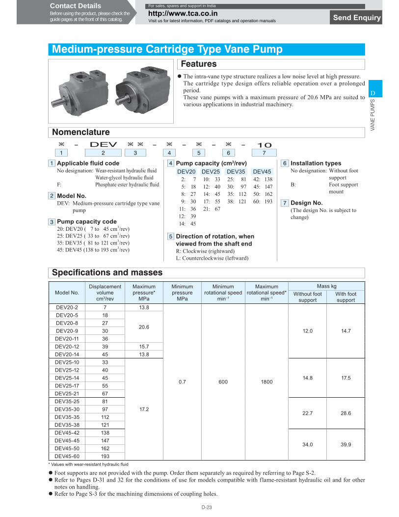
Medium-pressure Cartridge Type Vane PumpFeatures� The intra-vane type structure realizes a low noise level at high pressure.
The cartridge type design offers reliable operation over a prolonged period.These vane pumps with a maximum pressure of 20.6 MPa are suited to various applications in industrial machinery.
Applicable fluid codeNo designation: Wear-resistant hydraulic � uid
Water-glycol hydraulic � uidF: Phosphate ester hydraulic � uid
Model No.DEV: Medium-pressure cartridge type vane
pump
Pump capacity code20: DEV20 ( 7 to 45 cm3/rev)25: DEV25 ( 33 to 67 cm3/rev)35: DEV35 ( 81 to 121 cm3/rev)45: DEV45 ( 138 to 193 cm3/rev)
Pump capacity (cm3/rev)DEV20 DEV25 DEV35 DEV45
2: 7 10: 33 25: 81 42: 1385: 18 12: 40 30: 97 45: 1478: 27 14: 45 35: 112 50: 1629: 30 17: 55 38: 121 60: 193
11: 36 21: 6712: 3914: 45
Direction of rotation, when viewed from the shaft endR: Clockwise (rightward)L: Counterclockwise (leftward)
Nomenclature� - DEV � � - � - � - � - 101 2 3 4 5 6 7
Specifications and masses
Installation typesNo designation: Without foot
supportB: Foot support
mount
Design No.(The design No. is subject to change)
� Foot supports are not provided with the pump. Order them separately as required by referring to Page S-2.� Refer to Pages D-31 and 32 for the conditions of use for models compatible with flame-resistant hydraulic oil and for other
notes on handling.� Refer to Page S-3 for the machining dimensions of coupling holes.
* Values with wear-resistant hydraulic � uid
Model No.Displacement
volumecm3/rev
Maximum pressure*
MPa
Minimum pressure
MPa
Minimum rotational speed
min−1
Maximum rotational speed*
min−1
Mass kgWithout foot
supportWith foot support
DEV20-2 7 13.8
0.7 600 1800
12.0 14.7
DEV20-5 18
20.6DEV20-8 27DEV20-9 30DEV20-11 36DEV20-12 39 15.7DEV20-14 45 13.8DEV25-10 33
17.2
14.8 17.5DEV25-12 40DEV25-14 45DEV25-17 55DEV25-21 67DEV35-25 81
22.7 28.6DEV35-30 97DEV35-35 112DEV35-38 121DEV45-42 138
34.0 39.9DEV45-45 147DEV45-50 162DEV45-60 193
1
2
3
4 6
7
5
Contact DetailsBefore using the product, please check theguide pages at the front of this catalog.
For sales, spares and support in India
http://www.tca.co.inVisit us for latest information, PDF catalogs and operation manuals Send Enquiry
D-25
D
VAN
E P
UM
PS
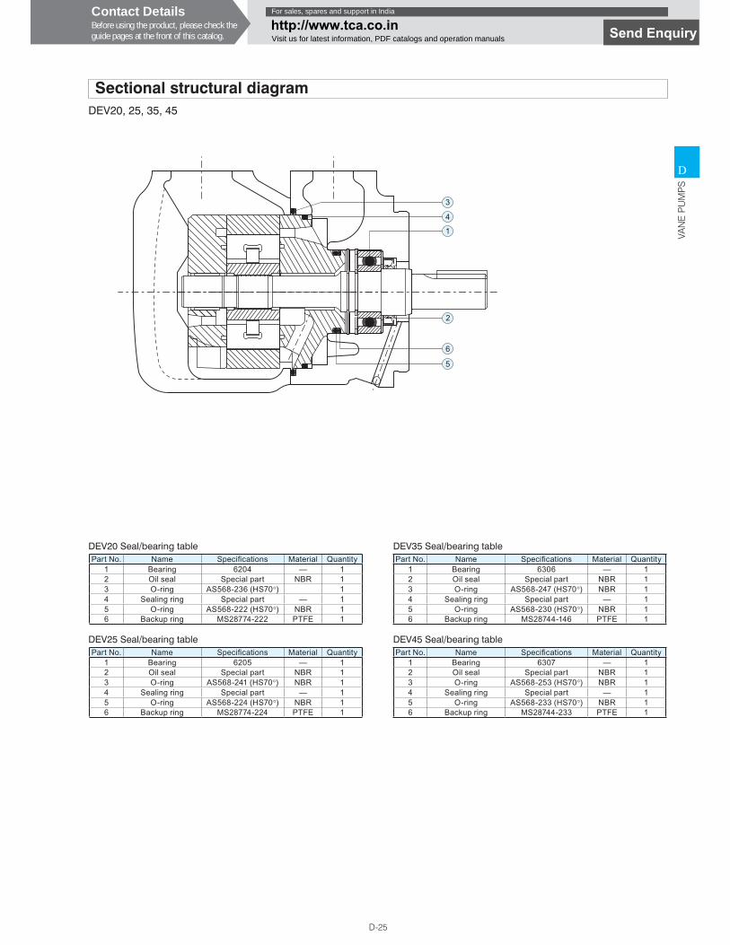
Sectional structural diagramDEV20, 25, 35, 45
Part No. Name Speci� cations Material Quantity1 Bearing 6204 — 12 Oil seal Special part NBR 13 O-ring AS568-236 (HS70°) 14 Sealing ring Special part — 15 O-ring AS568-222 (HS70°) NBR 16 Backup ring MS28774-222 PTFE 1
DEV20 Seal/bearing table
1
3
2
6
5
4
Part No. Name Speci� cations Material Quantity1 Bearing 6205 — 12 Oil seal Special part NBR 13 O-ring AS568-241 (HS70°) NBR 14 Sealing ring Special part — 15 O-ring AS568-224 (HS70°) NBR 16 Backup ring MS28774-224 PTFE 1
DEV25 Seal/bearing table
Part No. Name Speci� cations Material Quantity1 Bearing 6306 — 12 Oil seal Special part NBR 13 O-ring AS568-247 (HS70°) NBR 14 Sealing ring Special part — 15 O-ring AS568-230 (HS70°) NBR 16 Backup ring MS28744-146 PTFE 1
DEV35 Seal/bearing table
Part No. Name Speci� cations Material Quantity1 Bearing 6307 — 12 Oil seal Special part NBR 13 O-ring AS568-253 (HS70°) NBR 14 Sealing ring Special part — 15 O-ring AS568-233 (HS70°) NBR 16 Backup ring MS28744-233 PTFE 1
DEV45 Seal/bearing table
Contact DetailsBefore using the product, please check theguide pages at the front of this catalog.
For sales, spares and support in India
http://www.tca.co.inVisit us for latest information, PDF catalogs and operation manuals Send Enquiry
D-26
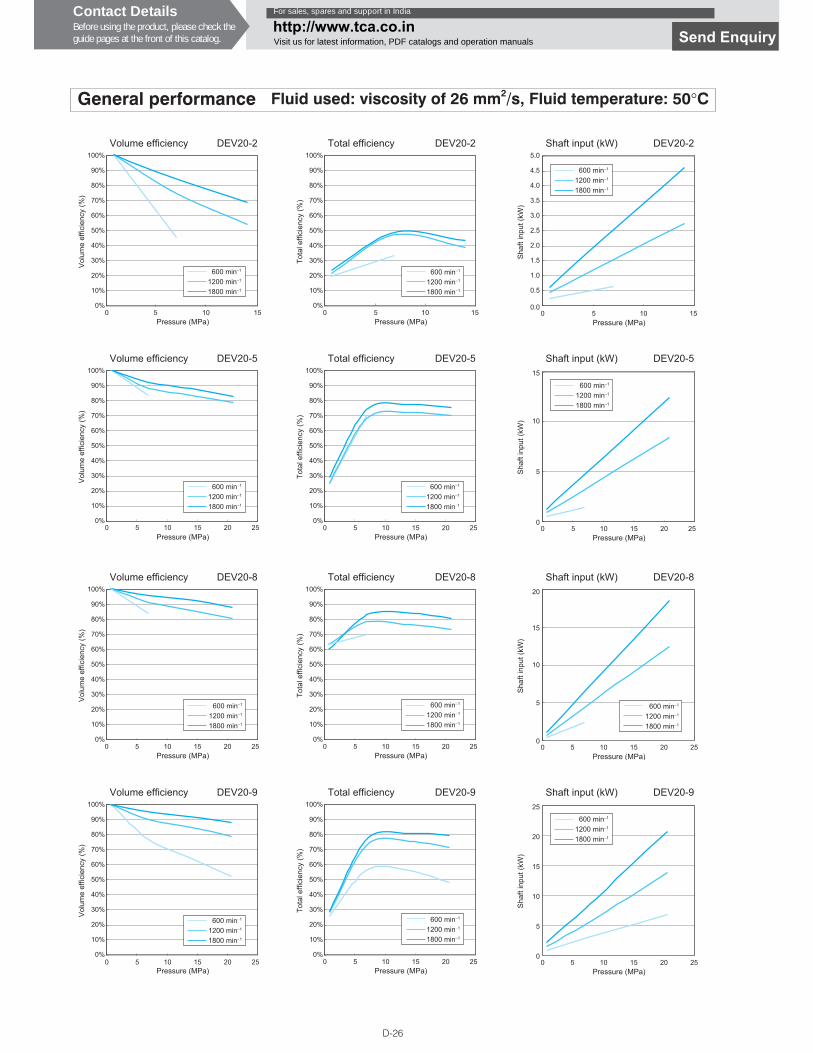
General performance Fluid used: viscosity of 26 mm2/s, Fluid temperature: 50°C
600 min−1
1200 min−1
1800 min−1
100%
90%
80%
70%
60%
50%
40%
30%
20%
10%
0%0 5
Pressure (MPa)
Volume efficiency DEV20-2
Vol
ume
effic
ienc
y (%
)
10 15
600 min−1
1200 min−1
1800 min−1
100%
90%
80%
70%
60%
50%
40%
30%
20%
10%
0%
Pressure (MPa)
Total efficiency DEV20-2
Tota
l effi
cien
cy (%
)
0 5 10 15
5.0
4.5
4.0
3.5
3.0
2.5
2.0
1.5
1.0
0.5
0.00 5
Pressure (MPa)
Shaft input (kW) DEV20-2
10 15
600 min−1
1200 min−1
1800 min−1
Sha
ft in
put (
kW)
600 min−1
1200 min−1
1800 min−1
100%
90%
80%
70%
60%
50%
40%
30%
20%
10%
0%
Pressure (MPa)
Volume efficiency DEV20-5
Vol
ume
effic
ienc
y (%
)
0 5 10 15 20 25
600 min−1
1200 min−1
1800 min−1
100%
90%
80%
70%
60%
50%
40%
30%
20%
10%
0%
Pressure (MPa)
Total efficiency DEV20-5
Tota
l effi
cien
cy (%
)
0 5 10 15 20 25
15
10
5
00 5
Pressure (MPa)
Shaft input (kW) DEV20-5
10 15 20 25
600 min−1
1200 min−1
1800 min−1
Sha
ft in
put (
kW)
600 min−1
1200 min−1
1800 min−1
100%
90%
80%
70%
60%
50%
40%
30%
20%
10%
0%
Pressure (MPa)
Volume efficiency DEV20-8
Vol
ume
effic
ienc
y (%
)
0 5 10 15 20 25
100%
90%
80%
70%
60%
50%
40%
30%
20%
10%
0%
Pressure (MPa)
Total efficiency DEV20-8
Tota
l effi
cien
cy (%
)
0 5 10 15 20 25
600 min−1
1200 min−1
1800 min−1
20
15
10
5
00 5
Pressure (MPa)
Shaft input (kW) DEV20-8
10 15 2520
600 min−1
1200 min−1
1800 min−1
Sha
ft in
put (
kW)
100%
90%
80%
70%
60%
50%
40%
30%
20%
10%
0%
Pressure (MPa)
Volume efficiency DEV20-9
Vol
ume
effic
ienc
y (%
)
0 5 10 15 20 25
600 min−1
1200 min−1
1800 min−1
600 min−1
1200 min−1
1800 min−1
100%
90%
80%
70%
60%
50%
40%
30%
20%
10%
0%
Pressure (MPa)
Total efficiency DEV20-9
Tota
l effi
cien
cy (%
)
0 5 10 15 20 25
25
20
15
10
5
00 5
Pressure (MPa)
Shaft input (kW) DEV20-9
10 15 2520
600 min−1
1200 min−1
1800 min−1
Sha
ft in
put (
kW)
Contact DetailsBefore using the product, please check theguide pages at the front of this catalog.
For sales, spares and support in India
http://www.tca.co.inVisit us for latest information, PDF catalogs and operation manuals Send Enquiry
D-27
D
VAN
E P
UM
PS
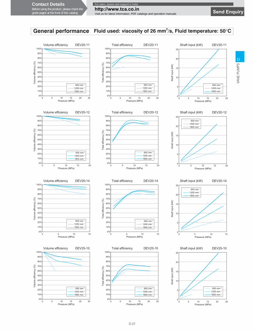
General performance Fluid used: viscosity of 26 mm2/s, Fluid temperature: 50°C
600 min−1
1200 min−1
1800 min−1
100%
90%
80%
70%
60%
50%
40%
30%
20%
10%
0%
Pressure (MPa)
Volume efficiency DEV20-11
Vol
ume
effic
ienc
y (%
)
0 5 10 15 20 25
600 min−1
1200 min−1
1800 min−1
100%
90%
80%
70%
60%
50%
40%
30%
20%
10%
0%
Pressure (MPa)
Total efficiency DEV20-11
Tota
l effi
cien
cy (%
)
0 5 10 15 20 25
25
20
15
10
5
00 5
Pressure (MPa)
Shaft input (kW) DEV20-11
10 15 2520
600 min−1
1200 min−1
1800 min−1
Sha
ft in
put (
kW)
100%
90%
80%
70%
60%
50%
40%
30%
20%
10%
0%0 5
Pressure (MPa)
Volume efficiency DEV20-12
Vol
ume
effic
ienc
y (%
)
10 15 20
600 min−1
1200 min−1
1800 min−1
100%
90%
80%
70%
60%
50%
40%
30%
20%
10%
0%0 5
Pressure (MPa)
Total efficiency DEV20-12
Tota
l effi
cien
cy (%
)
10 15 20
600 min−1
1200 min−1
1800 min−1
25
20
15
10
5
00 5
Pressure (MPa)
Shaft input (kW) DEV20-12
10 15 20
600 min−1
1200 min−1
1800 min−1
Sha
ft in
put (
kW)
100%
90%
80%
70%
60%
50%
40%
30%
20%
10%
0%
Pressure (MPa)
Volume efficiency DEV20-14
Vol
ume
effic
ienc
y (%
)
0 5 10 15
600 min−1
1200 min−1
1800 min−1
100%
90%
80%
70%
60%
50%
40%
30%
20%
10%
0%
Pressure (MPa)
Total efficiency DEV20-14
Tota
l effi
cien
cy (%
)
0 5 10 15
600 min−1
1200 min−1
1800 min−1
25
20
15
10
5
00 5
Pressure (MPa)
Shaft input (kW) DEV20-14
Sha
ft in
put (
kW)
10 15
600 min−1
1200 min−1
1800 min−1
100%
90%
80%
70%
60%
50%
40%
30%
20%
10%
0%
Pressure (MPa)
Volume efficiency DEV25-10
Vol
ume
effic
ienc
y (%
)
0 5 10 15 20 25
600 min−1
1200 min−1
1800 min−1
100%
90%
80%
70%
60%
50%
40%
30%
20%
10%
0%
Pressure (MPa)
Total efficiency DEV25-10
Tota
l effi
cien
cy (%
)
0 5 10 15 20 25
600 min−1
1200 min−1
1800 min−1
25
20
15
10
5
00 5
Pressure (MPa)
Shaft input (kW) DEV25-10
10 15 2520
600 min−1
1200 min−1
1800 min−1
Sha
ft in
put (
kW)
Contact DetailsBefore using the product, please check theguide pages at the front of this catalog.
For sales, spares and support in India
http://www.tca.co.inVisit us for latest information, PDF catalogs and operation manuals Send Enquiry
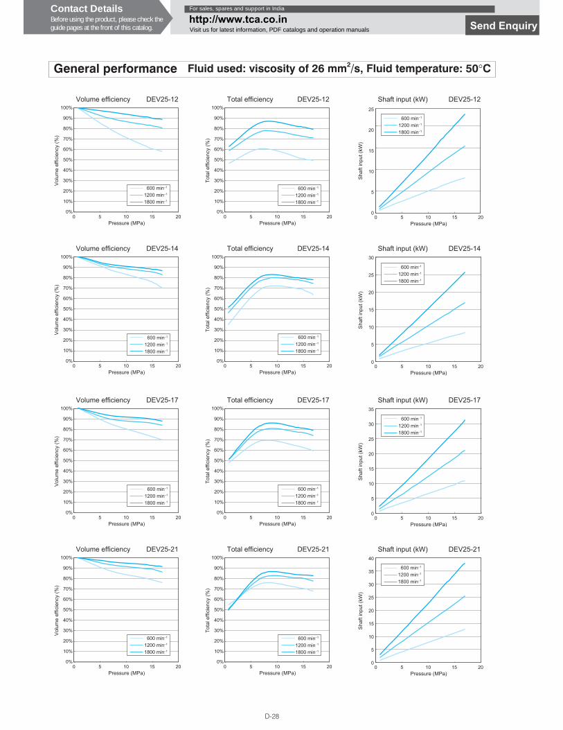
D-28
General performance Fluid used: viscosity of 26 mm2/s, Fluid temperature: 50°C
100%
90%
80%
70%
60%
50%
40%
30%
20%
10%
0%0 5
Pressure (MPa)
Volume efficiency DEV25-12
Vol
ume
effic
ienc
y (%
)
10 15 20
600 min−1
1200 min−1
1800 min−1
100%
90%
80%
70%
60%
50%
40%
30%
20%
10%
0%0 5
Pressure (MPa)
Total efficiency DEV25-12
Tota
l effi
cien
cy (%
)
10 15 20
600 min−1
1200 min−1
1800 min−1
25
20
15
10
5
00 5
Pressure (MPa)
Shaft input (kW) DEV25-12
10 15 20
600 min−1
1200 min−1
1800 min−1
Sha
ft in
put (
kW)
100%
90%
80%
70%
60%
50%
40%
30%
20%
10%
0%0 5
Pressure (MPa)
Volume efficiency DEV25-14
Vol
ume
effic
ienc
y (%
)
10 15 20
600 min−1
1200 min−1
1800 min−1
100%
90%
80%
70%
60%
50%
40%
30%
20%
10%
0%0 5
Pressure (MPa)
Total efficiency DEV25-14
Tota
l effi
cien
cy (%
)
10 15 20
600 min−1
1200 min−1
1800 min−1
30
20
10
25
15
5
00 5
Pressure (MPa)
Shaft input (kW) DEV25-14
10 15 20
600 min−1
1200 min−1
1800 min−1
Sha
ft in
put (
kW)
100%
90%
80%
70%
60%
50%
40%
30%
20%
10%
0%0 5
Pressure (MPa)
Volume efficiency DEV25-17
Vol
ume
effic
ienc
y (%
)
10 15 20
600 min−1
1200 min−1
1800 min−1
100%
90%
80%
70%
60%
50%
40%
30%
20%
10%
0%0 5
Pressure (MPa)
Total efficiency DEV25-17
Tota
l effi
cien
cy (%
)
10 15 20
600 min−1
1200 min−1
1800 min−1
35
30
25
20
5
15
10
00 5
Pressure (MPa)
Shaft input (kW) DEV25-17
10 15 20
600 min−1
1200 min−1
1800 min−1
Sha
ft in
put (
kW)
100%
90%
80%
70%
60%
50%
40%
30%
20%
10%
0%0 5
Pressure (MPa)
Volume efficiency DEV25-21
Vol
ume
effic
ienc
y (%
)
10 15 20
600 min−1
1200 min−1
1800 min−1
100%
90%
80%
70%
60%
50%
40%
30%
20%
10%
0%0 5
Pressure (MPa)
Total efficiency DEV25-21
Tota
l effi
cien
cy (%
)
10 15 20
600 min−1
1200 min−1
1800 min−1
40
35
30
25
20
15
10
5
00 5
Pressure (MPa)
Shaft input (kW) DEV25-21
10 15 20
600 min−1
1200 min−1
1800 min−1
Sha
ft in
put (
kW)
Contact DetailsBefore using the product, please check theguide pages at the front of this catalog.
For sales, spares and support in India
http://www.tca.co.inVisit us for latest information, PDF catalogs and operation manuals Send Enquiry
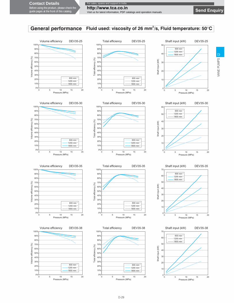
D-29
D
VAN
E P
UM
PS
General performance Fluid used: viscosity of 26 mm2/s, Fluid temperature: 50°C
100%
90%
80%
70%
60%
50%
40%
30%
20%
10%
0%0 5
Pressure (MPa)
Volume efficiency DEV35-25
Vol
ume
effic
ienc
y (%
)
10 15 20
600 min−1
1200 min−1
1800 min−1
100%
90%
80%
70%
60%
50%
40%
30%
20%
10%
0%0 5
Pressure (MPa)
Total efficiency DEV35-25
Tota
l effi
cien
cy (%
)
10 15 20
600 min−1
1200 min−1
1800 min−1
50
40
30
20
10
00 5
Pressure (MPa)
Shaft input (kW) DEV35-25
10 15 20
600 min−1
1200 min−1
1800 min−1
Sha
ft in
put (
kW)
100%
90%
80%
70%
60%
50%
40%
30%
20%
10%
0%0 5
Pressure (MPa)
Volume efficiency DEV35-30
Vol
ume
effic
ienc
y (%
)
10 15 20
600 min−1
1200 min−1
1800 min−1
100%
90%
80%
70%
60%
50%
40%
30%
20%
10%
0%0 5
Pressure (MPa)
Total efficiency DEV35-30
Tota
l effi
cien
cy (%
)
10 15 20
600 min−1
1200 min−1
1800 min−1
60
50
30
10
40
20
00 5
Pressure (MPa)
Shaft input (kW) DEV35-30
10 15 20
600 min−1
1200 min−1
1800 min−1
Sha
ft in
put (
kW)
100%
90%
80%
70%
60%
50%
40%
30%
20%
10%
0%0 5
Pressure (MPa)
Volume efficiency DEV35-35
Vol
ume
effic
ienc
y (%
)
10 15 20
600 min−1
1200 min−1
1800 min−1
100%
90%
80%
70%
60%
50%
40%
30%
20%
10%
0%0 5
Pressure (MPa)
Total efficiency DEV35-35
Tota
l effi
cien
cy (%
)
10 15 20
600 min−1
1200 min−1
1800 min−1
70
50
10
00 5
Pressure (MPa)
Shaft input (kW) DEV35-35
10 15 20
60
40
20
30
600 min−1
1200 min−1
1800 min−1
Sha
ft in
put (
kW)
100%
90%
80%
70%
60%
50%
40%
30%
20%
10%
0%0 5
Pressure (MPa)
Volume efficiency DEV35-38
Vol
ume
effic
ienc
y (%
)
10 15 20
600 min−1
1200 min−1
1800 min−1
100%
90%
80%
70%
60%
50%
40%
30%
20%
10%
0%0 5
Pressure (MPa)
Total efficiency DEV35-38
Tota
l effi
cien
cy (%
)
10 15 20
600 min−1
1200 min−1
1800 min−1
0 5Pressure (MPa)
Shaft input (kW) DEV35-38
10 15 20
70
50
10
0
60
40
20
30
600 min−1
1200 min−1
1800 min−1
Sha
ft in
put (
kW)
Contact DetailsBefore using the product, please check theguide pages at the front of this catalog.
For sales, spares and support in India
http://www.tca.co.inVisit us for latest information, PDF catalogs and operation manuals Send Enquiry
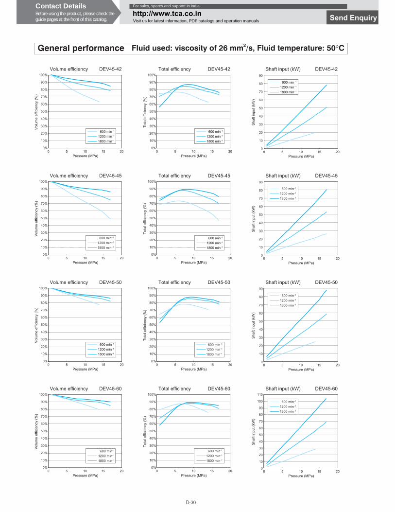
D-30
General performance Fluid used: viscosity of 26 mm2/s, Fluid temperature: 50°C
100%
90%
80%
70%
60%
50%
40%
30%
20%
10%
0%0 5
Pressure (MPa)
Volume efficiency DEV45-42
Vol
ume
effic
ienc
y (%
)
10 15 20
600 min−1
1200 min−1
1800 min−1
100%
90%
80%
70%
60%
50%
40%
30%
20%
10%
0%0 5
Pressure (MPa)
Total efficiency DEV45-42
Tota
l effi
cien
cy (%
)
10 15 20
600 min−1
1200 min−1
1800 min−1
90
80
70
60
50
40
20
10
30
00 5
Pressure (MPa)
Shaft input (kW) DEV45-42
10 15 20
600 min−1
1200 min−1
1800 min−1
Sha
ft in
put (
kW)
100%
90%
80%
70%
60%
50%
40%
30%
20%
10%
0%0 5
Pressure (MPa)
Volume efficiency DEV45-45
Vol
ume
effic
ienc
y (%
)
10 15 20
600 min−1
1200 min−1
1800 min−1
100%
90%
80%
70%
60%
50%
40%
30%
20%
10%
0%0 5
Pressure (MPa)
Total efficiency DEV45-45
Tota
l effi
cien
cy (%
)
10 15 20
600 min−1
1200 min−1
1800 min−1
0 5Pressure (MPa)
Shaft input (kW) DEV45-45
10 15 20
90
80
70
60
50
40
20
10
30
0
600 min−1
1200 min−1
1800 min−1
Sha
ft in
put (
kW)
100%
90%
80%
70%
60%
50%
40%
30%
20%
10%
0%0 5
Pressure (MPa)
Volume efficiency DEV45-50
Vol
ume
effic
ienc
y (%
)
10 15 20
600 min−1
1200 min−1
1800 min−1
100%
90%
80%
70%
60%
50%
40%
30%
20%
10%
0%0 5
Pressure (MPa)
Total efficiency DEV45-50
Tota
l effi
cien
cy (%
)
10 15 20
600 min−1
1200 min−1
1800 min−1
0 5Pressure (MPa)
Shaft input (kW) DEV45-50
10 15 20
90
80
70
60
50
40
20
10
30
0
600 min−1
1200 min−1
1800 min−1
Sha
ft in
put (
kW)
100%
90%
80%
70%
60%
50%
40%
30%
20%
10%
0%0 5
Pressure (MPa)
Volume efficiency DEV45-60
Vol
ume
effic
ienc
y (%
)
10 15 20
600 min−1
1200 min−1
1800 min−1
100%
90%
80%
70%
60%
50%
40%
30%
20%
10%
0%0 5
Pressure (MPa)
Total efficiency DEV45-60
Tota
l effi
cien
cy (%
)
10 15 20
600 min−1
1200 min−1
1800 min−1
0 5Pressure (MPa)
Shaft input (kW) DEV45-60
10 15 20
90
80
110
100
70
60
50
40
20
10
30
0
600 min−1
1200 min−1
1800 min−1
Sha
ft in
put (
kW)
Contact DetailsBefore using the product, please check theguide pages at the front of this catalog.
For sales, spares and support in India
http://www.tca.co.inVisit us for latest information, PDF catalogs and operation manuals Send Enquiry
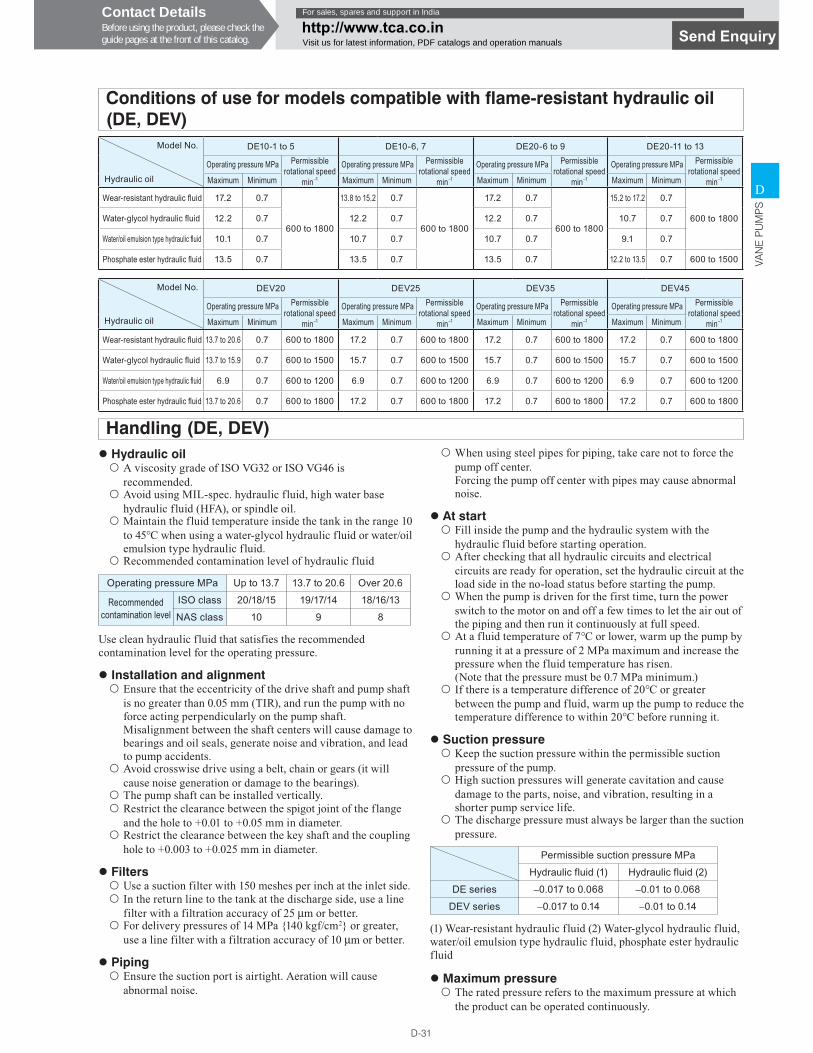
D-31
D
VAN
E P
UM
PS
Model No.
Hydraulic oil
DE10-1 to 5 DE10-6, 7 DE20-6 to 9 DE20-11 to 13
Operating pressure MPa Permissible rotational speed
min−1
Operating pressure MPa Permissible rotational speed
min−1
Operating pressure MPa Permissible rotational speed
min−1
Operating pressure MPa Permissible rotational speed
min−1Maximum Minimum Maximum Minimum Maximum Minimum Maximum Minimum
Wear-resistant hydraulic � uid 17.2 0.7
600 to 1800
13.8 to 15.2 0.7
600 to 1800
17.2 0.7
600 to 1800
15.2 to 17.2 0.7
600 to 1800Water-glycol hydraulic � uid 12.2 0.7 12.2 0.7 12.2 0.7 10.7 0.7
Water/oil emulsion type hydraulic � uid 10.1 0.7 10.7 0.7 10.7 0.7 9.1 0.7
Phosphate ester hydraulic � uid 13.5 0.7 13.5 0.7 13.5 0.7 12.2 to 13.5 0.7 600 to 1500
Handling (DE, DEV)
Conditions of use for models compatible with flame-resistant hydraulic oil (DE, DEV)
Model No.
Hydraulic oil
DEV20 DEV25 DEV35 DEV45
Operating pressure MPa Permissible rotational speed
min−1
Operating pressure MPa Permissible rotational speed
min−1
Operating pressure MPa Permissible rotational speed
min−1
Operating pressure MPa Permissible rotational speed
min−1Maximum Minimum Maximum Minimum Maximum Minimum Maximum Minimum
Wear-resistant hydraulic � uid 13.7 to 20.6 0.7 600 to 1800 17.2 0.7 600 to 1800 17.2 0.7 600 to 1800 17.2 0.7 600 to 1800
Water-glycol hydraulic � uid 13.7 to 15.9 0.7 600 to 1500 15.7 0.7 600 to 1500 15.7 0.7 600 to 1500 15.7 0.7 600 to 1500
Water/oil emulsion type hydraulic � uid 6.9 0.7 600 to 1200 6.9 0.7 600 to 1200 6.9 0.7 600 to 1200 6.9 0.7 600 to 1200
Phosphate ester hydraulic � uid 13.7 to 20.6 0.7 600 to 1800 17.2 0.7 600 to 1800 17.2 0.7 600 to 1800 17.2 0.7 600 to 1800
� Hydraulic oil��A viscosity grade of ISO VG32 or ISO VG46 is
recommended.��Avoid using MIL-spec. hydraulic fluid, high water base
hydraulic fluid (HFA), or spindle oil.��Maintain the fluid temperature inside the tank in the range 10
to 45°C when using a water-glycol hydraulic fluid or water/oil emulsion type hydraulic fluid.
��Recommended contamination level of hydraulic fluid
Operating pressure MPa Up to 13.7 13.7 to 20.6 Over 20.6
Recommended contamination level
ISO class 20/18/15 19/17/14 18/16/13
NAS class 10 9 8
Use clean hydraulic fluid that satisfies the recommended contamination level for the operating pressure.
� Installation and alignment��Ensure that the eccentricity of the drive shaft and pump shaft
is no greater than 0.05 mm (TIR), and run the pump with no force acting perpendicularly on the pump shaft.Misalignment between the shaft centers will cause damage to bearings and oil seals, generate noise and vibration, and lead to pump accidents.
��Avoid crosswise drive using a belt, chain or gears (it will cause noise generation or damage to the bearings).
��The pump shaft can be installed vertically.��Restrict the clearance between the spigot joint of the flange
and the hole to +0.01 to +0.05 mm in diameter.��Restrict the clearance between the key shaft and the coupling
hole to +0.003 to +0.025 mm in diameter.
� Filters��Use a suction filter with 150 meshes per inch at the inlet side.��In the return line to the tank at the discharge side, use a line
filter with a filtration accuracy of 25 μm or better.��For delivery pressures of 14 MPa {140 kgf/cm2} or greater,
use a line filter with a filtration accuracy of 10 μm or better.
� Piping��Ensure the suction port is airtight. Aeration will cause
abnormal noise.
��When using steel pipes for piping, take care not to force the pump off center.Forcing the pump off center with pipes may cause abnormal noise.
� At start��Fill inside the pump and the hydraulic system with the
hydraulic fluid before starting operation.��After checking that all hydraulic circuits and electrical
circuits are ready for operation, set the hydraulic circuit at the load side in the no-load status before starting the pump.
��When the pump is driven for the first time, turn the power switch to the motor on and off a few times to let the air out of the piping and then run it continuously at full speed.
��At a fluid temperature of 7°C or lower, warm up the pump by running it at a pressure of 2 MPa maximum and increase the pressure when the fluid temperature has risen.(Note that the pressure must be 0.7 MPa minimum.)
��If there is a temperature difference of 20°C or greater between the pump and fluid, warm up the pump to reduce the temperature difference to within 20°C before running it.
� Suction pressure��Keep the suction pressure within the permissible suction
pressure of the pump.��High suction pressures will generate cavitation and cause
damage to the parts, noise, and vibration, resulting in a shorter pump service life.
��The discharge pressure must always be larger than the suction pressure.
Permissible suction pressure MPa
Hydraulic fluid (1) Hydraulic fluid (2)
DE series −0.017 to 0.068 −0.01 to 0.068
DEV series −0.017 to 0.14 −0.01 to 0.14
(1) Wear-resistant hydraulic fluid (2) Water-glycol hydraulic fluid, water/oil emulsion type hydraulic fluid, phosphate ester hydraulic fluid
� Maximum pressure��The rated pressure refers to the maximum pressure at which
the product can be operated continuously.
Contact DetailsBefore using the product, please check theguide pages at the front of this catalog.
For sales, spares and support in India
http://www.tca.co.inVisit us for latest information, PDF catalogs and operation manuals Send Enquiry
D-32
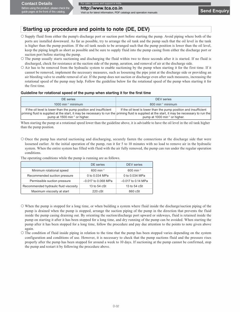
Starting up procedure and points to note (DE, DEV)��Supply fluid from either the pump's discharge port or suction port before starting the pump. Avoid piping where both of the
ports are installed downward. As far as possible, try to arrange the oil tank and the pump such that the oil level in the tank is higher than the pump position. If the oil tank needs to be arranged such that the pump position is lower than the oil level, keep the piping length as short as possible and be sure to supply fluid into the pump casing from either the discharge port or suction port before starting the pump.
��The pump usually starts suctioning and discharging the fluid within two to three seconds after it is started. If no fluid is discharged, check for resistance at the suction side of the pump, aeration, and removal of air at the discharge side.
��Air has to be removed from the hydraulic system to enable suctioning by the pump when starting it for the first time. If it cannot be removed, implement the necessary measures, such as loosening the pipe joint at the discharge side or providing an air bleeding valve to enable removal of air. If the pump does not suction or discharge even after such measures, increasing the rotational speed of the pump may help. Follow the guideline below for the rotational speed of the pump when starting it for the first time.
��Once the pump has started suctioning and discharging, securely fasten the connections at the discharge side that were loosened earlier. At the initial operation of the pump, run it for 5 to 10 minutes with no load to remove air in the hydraulic system. When the entire system has filled with fluid with the air fully removed, the pump can run under the regular operation conditions.
��When the pump is stopped for a long time, or when building a system where fluid inside the discharge/suction piping of the pump is drained when the pump is stopped, arrange the suction piping of the pump in the direction that prevents the fluid inside the pump casing draining out. By orienting the suction/discharge port upward or sideways, fluid is retained inside the pump on starting it after it has been stopped for a long time, and dry running of the pump can be avoided. When starting the pump after it has been stopped for a long time, follow the procedure and pay due attention to the points to note given above again.
��The condition of fluid inside piping in relation to the time that the pump has been stopped varies depending on the system configuration and conditions of use. However, it is necessary to check that the pump suctions fluid and the pressure rises properly after the pump has been stopped for around a week to 10 days. If suctioning at the pump cannot be confirmed, stop the pump and restart it by following the procedure above.
Guideline for rotational speed of the pump when starting it for the first time
DE series DEV series1000 min�1 minimum 800 min�1 minimum
If the oil level is lower than the pump position and insufficient priming fluid is supplied at the start, it may be necessary to run the
pump at 1500 min�1 or higher.
If the oil level is lower than the pump position and insufficient priming fluid is supplied at the start, it may be necessary to run the
pump at 1000 min�1 or higher.
When starting the pump at a rotational speed lower than the guideline above, it is advisable to have the oil level in the oil tank higher than the pump position.
DE series DEV series
Minimum rotational speed 600 min−1 600 min−1
Recommended suction pressure 0 to 0.034 MPa 0 to 0.034 MPa
Permissible suction pressure −0.017 to 0.068 MPa −0.017 to 0.14 MPaRecommended hydraulic fluid viscosity 13 to 54 cSt 13 to 54 cSt
Maximum viscosity at start 220 cSt 860 cSt
The operating conditions while the pump is running are as follows.
Contact DetailsBefore using the product, please check theguide pages at the front of this catalog.
For sales, spares and support in India
http://www.tca.co.inVisit us for latest information, PDF catalogs and operation manuals Send Enquiry
D-33
D
GE
AR
PU
MP
S
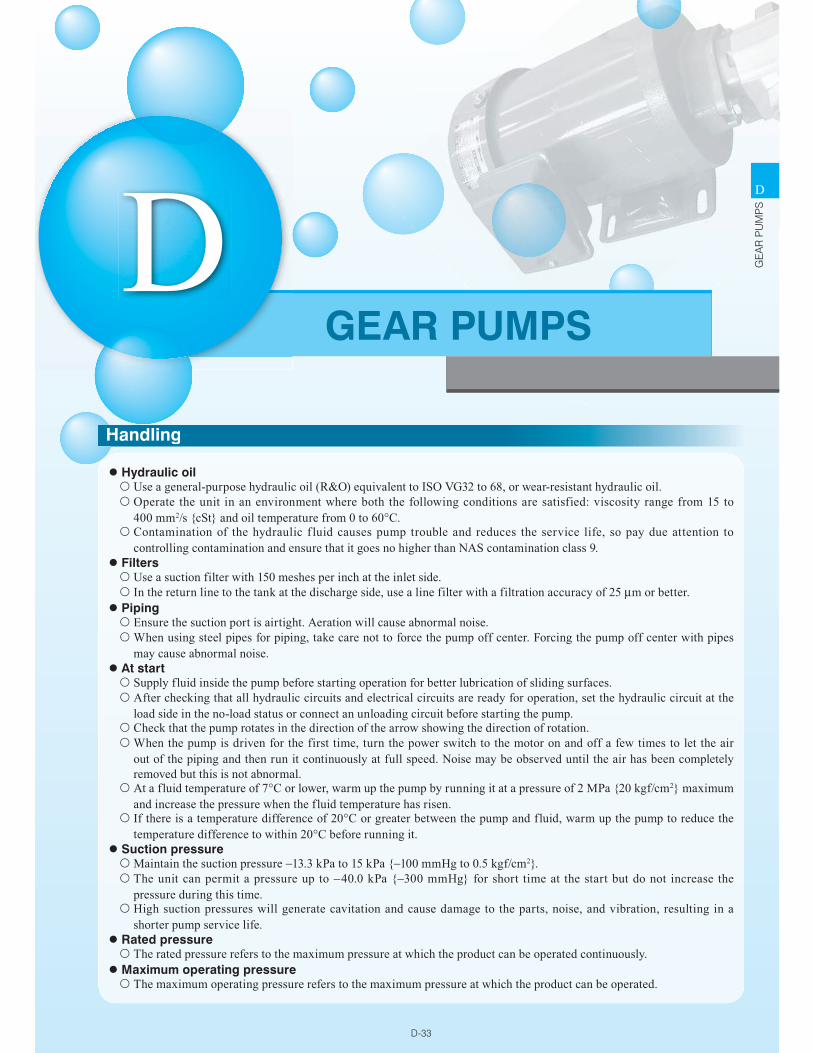
� Hydraulic oil��Use a general-purpose hydraulic oil (R&O) equivalent to ISO VG32 to 68, or wear-resistant hydraulic oil.��Operate the unit in an environment where both the following conditions are satisfied: viscosity range from 15 to
400 mm2/s {cSt} and oil temperature from 0 to 60°C.��Contamination of the hydraulic f luid causes pump trouble and reduces the service life, so pay due attention to
controlling contamination and ensure that it goes no higher than NAS contamination class 9.� Filters��Use a suction filter with 150 meshes per inch at the inlet side.��In the return line to the tank at the discharge side, use a line filter with a filtration accuracy of 25 μm or better.
� Piping��Ensure the suction port is airtight. Aeration will cause abnormal noise.��When using steel pipes for piping, take care not to force the pump off center. Forcing the pump off center with pipes
may cause abnormal noise.� At start��Supply fluid inside the pump before starting operation for better lubrication of sliding surfaces.��After checking that all hydraulic circuits and electrical circuits are ready for operation, set the hydraulic circuit at the
load side in the no-load status or connect an unloading circuit before starting the pump.��Check that the pump rotates in the direction of the arrow showing the direction of rotation.��When the pump is driven for the first time, turn the power switch to the motor on and off a few times to let the air
out of the piping and then run it continuously at full speed. Noise may be observed until the air has been completely removed but this is not abnormal.
��At a fluid temperature of 7°C or lower, warm up the pump by running it at a pressure of 2 MPa {20 kgf/cm2} maximum and increase the pressure when the fluid temperature has risen.
��If there is a temperature difference of 20°C or greater between the pump and fluid, warm up the pump to reduce the temperature difference to within 20°C before running it.
� Suction pressure��Maintain the suction pressure −13.3 kPa to 15 kPa {−100 mmHg to 0.5 kgf/cm2}.��The unit can permit a pressure up to −40.0 kPa {−300 mmHg} for short time at the start but do not increase the
pressure during this time.��High suction pressures will generate cavitation and cause damage to the parts, noise, and vibration, resulting in a
shorter pump service life.� Rated pressure��The rated pressure refers to the maximum pressure at which the product can be operated continuously.
� Maximum operating pressure��The maximum operating pressure refers to the maximum pressure at which the product can be operated.
DGEAR PUMPS
HandlingH
D-34
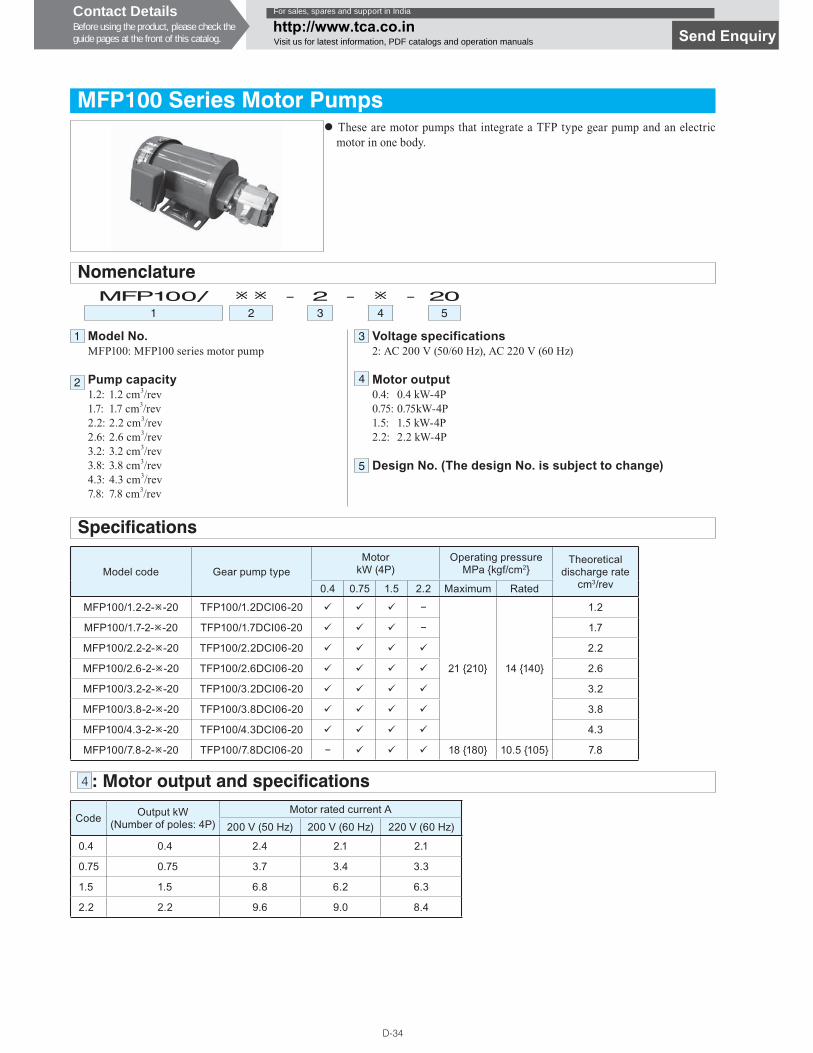
MFP100 Series Motor Pumps
Model No.MFP100: MFP100 series motor pump
Pump capacity1.2: 1.2 cm3/rev1.7: 1.7 cm3/rev2.2: 2.2 cm3/rev2.6: 2.6 cm3/rev3.2: 3.2 cm3/rev3.8: 3.8 cm3/rev4.3: 4.3 cm3/rev7.8: 7.8 cm3/rev
Voltage specifications2: AC 200 V (50/60 Hz), AC 220 V (60 Hz)
Motor output0.4: 0.4 kW-4P0.75: 0.75kW-4P1.5: 1.5 kW-4P2.2: 2.2 kW-4P
Design No. (The design No. is subject to change)
MFP100/ � � - 2 - � - 201 2 3 4 5
Nomenclature
Specifications
Model code Gear pump typeMotor
kW (4P)Operating pressure
MPa {kgf/cm2}Theoretical
discharge ratecm3/rev0.4 0.75 1.5 2.2 Maximum Rated
MFP100/1.2-2-�-20 TFP100/1.2DCI06-20 � � � �
21 {210} 14 {140}
1.2
MFP100/1.7-2-�-20 TFP100/1.7DCI06-20 � � � � 1.7
MFP100/2.2-2-�-20 TFP100/2.2DCI06-20 � � � � 2.2
MFP100/2.6-2-�-20 TFP100/2.6DCI06-20 � � � � 2.6
MFP100/3.2-2-�-20 TFP100/3.2DCI06-20 � � � � 3.2
MFP100/3.8-2-�-20 TFP100/3.8DCI06-20 � � � � 3.8
MFP100/4.3-2-�-20 TFP100/4.3DCI06-20 � � � � 4.3
MFP100/7.8-2-�-20 TFP100/7.8DCI06-20 � � � � 18 {180} 10.5 {105} 7.8
4 : Motor output and specifications
Code Output kW(Number of poles: 4P)
Motor rated current A
200 V (50 Hz) 200 V (60 Hz) 220 V (60 Hz)
0.4 0.4 2.4 2.1 2.1
0.75 0.75 3.7 3.4 3.3
1.5 1.5 6.8 6.2 6.3
2.2 2.2 9.6 9.0 8.4
� These are motor pumps that integrate a TFP type gear pump and an electric motor in one body.
1
2
5
3
4
Contact DetailsBefore using the product, please check theguide pages at the front of this catalog.
For sales, spares and support in India
http://www.tca.co.inVisit us for latest information, PDF catalogs and operation manuals Send Enquiry
D-35
D
GE
AR
PU
MP
S
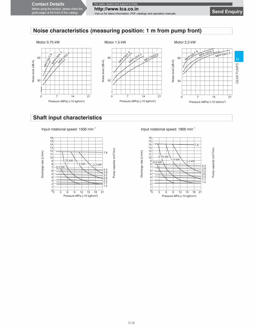
Noise characteristics (measuring position: 1 m from pump front)
Shaft input characteristics
Motor 0.75 kW Motor 1.5 kW Motor 2.2 kW
Input rotational speed: 1500 min−1 Input rotational speed: 1800 min−1
60
50
0 7 14 21
MFP
100/
7.8
MFP10
0/4.3
MFP100/2
.6
Pressure (MPa) {×10 kgf/cm2}
Noi
se le
vel (
dB-A
)
60
50
0 7 14 21
MFP100/7
.8
MFP100/4.3
MFP100/2.6
Pressure (MPa) {×10 kgf/cm2}N
oise
leve
l (dB
-A) 60
50
0 7 14 21
MFP100/7.8MFP100/4.3
MFP100/3.2
Pressure (MPa) {×10 kgf/cm2}
Noi
se le
vel (
dB-A
)
161514131211109876543210
7.8
4.33.83.22.62.21.71.2
0 3 6 9 12 15 18 21Pressure MPa {×10 kgf/cm2}
Pum
p ca
paci
ty (c
m3 /re
v)
Dis
char
ge ra
te ( L
/min
)
0.4 kW
0.75 kW1.5 kW 2.2 kW
161514131211109876543210
7.8
4.33.83.22.62.21.71.2
0 3 6 9 12 15 18 21
0.4 kW
0.75 kW1.5 kW 2.2 kW
Pressure MPa {×10 kgf/cm2}
Pum
p ca
paci
ty (c
m3 /re
v)
Dis
char
ge ra
te (L
/min
)
Contact DetailsBefore using the product, please check theguide pages at the front of this catalog.
For sales, spares and support in India
http://www.tca.co.inVisit us for latest information, PDF catalogs and operation manuals Send Enquiry
DAIKIN INDUSTRIES, LTD. Oil Hydraulic Equipment
Osaka OfficeYODOGAWA PLANT1-1, Nishi-Hitotsuya, Settsu, Osaka 566-8585, Japan
Indian RepresentativeTechnocrats Alliance Engineering Pvt. Ltd.Works/Correspondence Office : 11/23, TIL Compound, Site-IV,Sahibabad Industrial. Area, Ghaziabad - 201010 (UP) INDIA
Registered Office : C - 12 / 333, Yamuna Vihar, Delhi - 110053 INDIATel: +91-11- 42448311, 22448312 Fax: +91-11-4248312E-mail : [email protected] website : www.tca.co.in