Embed Size (px)
Citation preview
DAHLGREN DIVISION NAVAL SURFACE WARFARE CENTER Dahlgren, Virginia 22448-5100
2003 Joint Service Scientific Conference on Chemical & Biological Defense Research
Over-water Simulant Release Testing for the Joint Services Lightweight Standoff
Chemical Agent Detector (JSLSCAD) April 2004 By Daniel Driscoll, Brian Patrick, Gregory Johnson, Katherine Patton-Hall, Gary M. Turman, Mike Cornwell, Brian Stelmok, Rob Kinter Abstract: NSWCDD Has supported the JSLSCAD program through participation in joint IPTs for system development, logistics, and test and evaluation. As part of its role in support of Test and Evaluation NSWC performed over water testing of the JSLSCAD on its Potomac River Test Range in July/August of this year. Testing over water presents several unique challenges, foremost being to question of how to adequately referee the simulant challenge, and how to safely and effectively provide that challenge. By using a combination of Infrared (IR) cameras, and M&S tools coupled to on the spot meteorological observations we predicted cloud track, and attempted to verify cloud behavior. Issues encountered included speed of coordinating met observations, and tests, and the sometimes-volatile nature of weather conditions in the littoral environment.

Report Documentation Page Form ApprovedOMB No. 0704-0188
Public reporting burden for the collection of information is estimated to average 1 hour per response, including the time for reviewing instructions, searching existing data sources, gathering andmaintaining the data needed, and completing and reviewing the collection of information. Send comments regarding this burden estimate or any other aspect of this collection of information,including suggestions for reducing this burden, to Washington Headquarters Services, Directorate for Information Operations and Reports, 1215 Jefferson Davis Highway, Suite 1204, ArlingtonVA 22202-4302. Respondents should be aware that notwithstanding any other provision of law, no person shall be subject to a penalty for failing to comply with a collection of information if itdoes not display a currently valid OMB control number.
1. REPORT DATE 01 OCT 2005
2. REPORT TYPE N/A
3. DATES COVERED -
4. TITLE AND SUBTITLE Over-water Simulant Release Testing for the Joint Services LightweightStandoff Chemical Agent Detector (JSLSCAD)
5a. CONTRACT NUMBER
5b. GRANT NUMBER
5c. PROGRAM ELEMENT NUMBER
6. AUTHOR(S) 5d. PROJECT NUMBER
5e. TASK NUMBER
5f. WORK UNIT NUMBER
7. PERFORMING ORGANIZATION NAME(S) AND ADDRESS(ES) DAHLGREN DIVISION NAVAL SURFACE WARFARE CENTERDahlgren, Virginia 22448-5100
8. PERFORMING ORGANIZATIONREPORT NUMBER
9. SPONSORING/MONITORING AGENCY NAME(S) AND ADDRESS(ES) 10. SPONSOR/MONITOR’S ACRONYM(S)
11. SPONSOR/MONITOR’S REPORT NUMBER(S)
12. DISTRIBUTION/AVAILABILITY STATEMENT Approved for public release, distribution unlimited
13. SUPPLEMENTARY NOTES See also ADM001851, Proceedings of the 2003 Joint Service Scientific Conference on Chemical &Biological Defense Research, 17-20 November 2003. , The original document contains color images.
14. ABSTRACT
15. SUBJECT TERMS
16. SECURITY CLASSIFICATION OF: 17. LIMITATION OF ABSTRACT
UU
18. NUMBEROF PAGES
19
19a. NAME OFRESPONSIBLE PERSON
a. REPORT unclassified
b. ABSTRACT unclassified
c. THIS PAGE unclassified
Standard Form 298 (Rev. 8-98) Prescribed by ANSI Std Z39-18

FOREWORD
This test report addresses the Navy developmental test (DT) phase for the Joint Service Lightweight Standoff Chemical Agent Detector (JSLSCAD). Designated DT-IIA and DT-IIB in the Test and Evaluation Master Plan (TEMP), this testing was conducted at the Naval Surface Warfare Center Dahlgren Division (NSWCDD), Dahlgren, Virginia site (NSWCDL) from July 21, 2003 through August 5, 2003.
The JSLSCAD is an ACAT III program and consists of a fully automated detector with scanning capability. The JSLSCAD will be used by all the services and on several platforms. The system tested at NSWCDD was the land based fixed site configuration of JSLSCAD, although in all important signal processing and hardware configuration parameters it is identical to the shipboard application of this system.
The scope of the Navy DT event comprised several tests aimed at verifying that the system will perform as expected in the Navy environment. Among these tests was the over-water testing of the JSLSCAD system, which consisted of challenges using simulants in near-operational conditions. The tests sought to identify operational and technological capabilities and potential limitations of the system and provide data and analysis in support of the decision to certify the system ready for operational test and evaluation.
1
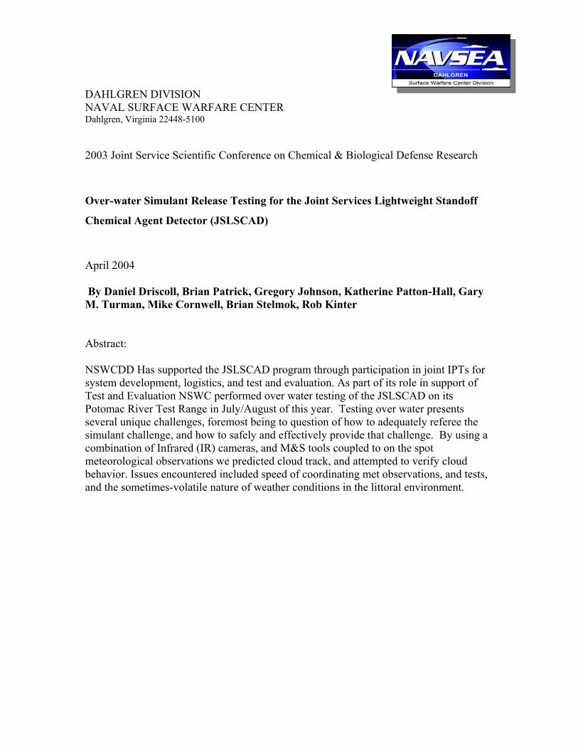
CONTENTS
ILLUSTRATIONS Figure Page
1 JSLSCAD SEM and Power Adapter…………………………………10 2 JSLSCAD Operator Display Unit……………………………………10 3 Dispersal Stack and Blower on Simulant release boat Gatlin ……….12 4 Simulant Dispersal Atomizing Spray Nozzle………………………..12 5 Simulant Release Boat operating on the PRTR.……………………..13 6 Map of Test Area on Potomac River Test Range (PRTR)…………...16
TABLES
Table Page
1 Typical Test Day Schedule ………………………………………………..15
2 Boat Heading and Start Point vs. Wind Direction ………………………...16
3 Matrix of Simulant Releases Conducted ………………………………….17
4 Acceptable Weather Limits for Test ………………………………..17
5 Weather Conditions During Each Release …………………………18
2

GLOSSARY
ACAT Acquisition Category CBIRF Chemical Biological Incident Response Force CIC Combat Information Center CL Concentration (times) Pathlength CW Chemical Warfare DT Developmental Testing EA Environmental Assessment ETF Experimental Test Facility FOR Field-of-regard FOV Field-of-rview FTIR Fourier Transform Infrared Spectroscopy GAA Glacial Acetic Acid GPS Global Positioning System HAZMAT Hazardous Material HPAC Hazard Prediction and Assessment Capability HYSPLIT Hybrid Single-Particle Lagrangian Integrated Trajectory ID Inside Diameter IR Infrared JSLSCAD Joint Service Lightweight Standoff Chemical Agent Detector MDE Maryland Department of the Environment Met Meteorological M&S Modeling and Simulation NLMOC Naval Atlantic Meteorology and Oceanography Center NOAA National Oceanic and Atmospheric Association NSWCDD Naval Surface Warfare Center Dahlgren Division NSWCDL Naval Surface Warfare Center Dahlgren Laboratory (site) ODU Operator Display Unit OT Operational Testing OTD Operational Test Director PA Power Adapter PRTR Potomac River Test Range – approximately 3 x 16 nautical miles RH Relative Humidity SBCCOM Soldier Biological Chemical Command SEM Sensor Electronics Module SF6 Sulfur Hexafluoride
3

SM Scanner Module SOP Standard Operating Procedure(s) STSTS Search and track sensor test site TCP Transmission Control Protocol TD Test Director TEMP Test and Evaluation Master Plan TEP Triethyl Phosphate TU Test Unit UDP User Datagram Protocol VDC Volts Direct Current g/L grams per liter km kilometers µm micron (10-6 m) mg/kg milligrams per kilogram mg/m3 milligrams per cubic meter mm Hg millimeters of mercury ppm parts per million
4

BACKGROUND INFORMATION
The Joint Service Lightweight Standoff Chemical Agent Detector (JSLSCAD) system detects the presence of chemical warfare (CW) agent vapor clouds at distances up to 5 kilometers (km) from stationary or on-the-move platforms. The system uses Fourier transform infrared spectroscopy (FTIR) technology to detect and classify threats based on their emission and absorption characteristics in the 8-12-µm region of the electromagnetic spectrum. This test report addresses the Navy developmental testing (DT) for JSLSCAD, conducted at the Naval Surface Warfare Center Dahlgren Division (NSWCDD), Potomac River Test Range (PRTR). The purpose for the Navy DT phase was to ascertain the ability of the JSLSCAD system to operate in the maritime environment under near operational conditions. Navy DT for JSLSCAD is required per the Test and Evaluation Master Plan (TEMP). Following the Navy DT phase, and after the operational test director’s (OTD) approval, operational testing (OT) will begin.
The Navy DT at NSWCDL consisted of three parts: Part I is the initial checkout, which included laboratory challenges to the detector system; Part II is the over-water test described by this test report; Part III includes all the environmental survivability tests required for shipboard equipment. Part III was terminated prior to completion due to program issues.
Part II of the JSLSCAD Navy DT test phase was abbreviated due to programmatic issues which dictated a pause in the program. The scope of DT Part II was reduced to five simulant releases each with the simulants SF6, TEP and Acetic Acid. Future tests will be conducted to resolve any uncertainty about the operational effectiveness of this system or its replacement in the eyes of the Navy warfighter.
PARTICIPANTS
Because of the variety of resources needed to carry out the test, many groups within NSWCDD participated in the over-water test event. Other services and agencies were present as observers. NSWCDD-B56, the Chemical, Biological, and Radiological Detection Systems Branch, had primary responsibility for the test event. The entire list of participants and responsibilities is as follows:
NSWCDD-B56. Chemical, Biological, and Radiological Detection Systems Branch responsibilities:
a. Overall planning of the test b. Write and obtain approval of Standard Operating
Procedures (SOPs) for the test c. Accept and perform initial checkout of Test Items d. Procure simulants required for test e. Procure non-dissemination equipment needed for test
5

f. Coordinate test efforts with other NSWCDD departments
g. Coordinate testing to be performed by outside contractors at their facilities
h. Review Environmental Assessment documentation and coordinate approval
NSWCDD-T43. Special Systems Branch responsibilities:
a. Design, procure, assemble, and test simulant dissemination equipment
b. Operate the test platform (boat) c. Engineering support (dissemination equipment) d. Operate the dissemination equipment e. Collect and relay GPS and other relevant data from the
release area NSWCDD-T44. Technology and Photonic Systems Branch responsibilities:
a. Design and test simulant dissemination equipment b. Engineering support (dissemination equipment) c. Analysis support (Environmental Assessment Report) d. Coordinate and participate in testing at contractor
facility e. Engineering support (test event) f. Develop and operate “Reference System” to monitor
simulant clouds g. Provide meteorological (met) data from the release boat h. Provide release boat data from the operational area i. Coordinate participation of outside M&S groups
NSWCDD-G604. Potomac River Test Range responsibilities:
a. Range surveillance and control b. Supply meteorological data at NSWCDD Range
Control c. Supply equipment to load and unload dissemination
equipment into and out of test vessel
Defense Threat Reduction Agency (DTRA) responsibilities: a. Modeling and Simulation support b. Post-test cloud track prediction
6

Naval Atlantic Meteorology & Oceanography Command (NLMOC ) Participation:
a. HPAC, HYSPLIT Runs, and high resolution weather model Meso Scale Meteorological modeling
b. De-conflicting HPAC and HYSPLIT modeling results
National Oceanographic & Atmospheric Administration (NOAA) Participation
a. NOAA mesoscale forecast windfield and HYSPLIT Runs b. Coordination of M&S Met Modeling with NLMOC c. De-conflicting HPAC and HYSPLIT modeling results.
OBSERVERS
a. JSLSCAD Army representatives (PM NBC Defense Systems (PM NBCDS)) b. Maryland Department of the Environment (MDE) and their contractors c. US Army Soldier Biological and Chemical Command (SBCCOM) Scientist. d. Marine Corps’ Chemical Biological Incident Response Force (CBIRF) e. Physical Sciences Inc. Scientist.
TEST ITEMS
SYSTEM DESCRIPTION
The fielded JSLSCAD system consists of four major components:
• Scanner Module (SM). Covers a Field-of-regard (FOR) of 360º azimuth, and 60º (−10º + 50º) elevation.
• Sensor Electronics Module (SEM). Optics and electronics that make up the detector. Includes embedded signal processing.
The SM and SEM are fastened together and commonly referred to as the SM/SEM unit .
• Operator Display Unit (ODU). The computer display that provides threat information to operator, and provides control interface to the detector unit (SM/SEM).
• Power Adapter (PA). Provides 28 volts direct current (VDC) (converted from 115Vac) to the SEM.
The operational shipboard configuration, referred to as the dual configuration, will consist of two SM/SEM units, two PA units, and two ODUs. The system is controlled via the master ODU (when deployed to the fleet, the master ODU will be located at Combat Information Center (CIC). The second (slave) unit will be located on
7

the bridge.) The ODU also displays information regarding threat cloud location (bearing) and the type of threat (blister, nerve, blood).
Each test article for the Navy DT test phase consisted of one SM/SEM, one ODU, and one PA. During the Navy test phase the JSLSCAD “single configuration” was used to avoid schedule delays, allow simultaneous tests, increase the number of observation points, and maximize data collection in general.
SYSTEM OPERATION
The JSLSCAD system detects the presence of a vapor cloud by collecting the energy that enters its 1.5º field-of-view (FOV). The energy collected is in effect the relative temperature differential between the target cloud and the background at each sampled wavelength; the vapor cloud may absorb or emit energy in the infrared (IR) region of the electromagnetic spectrum. A large temperature difference between vapor cloud and background will significantly enhance detection sensitivity. Sensitivity is expressed in terms of concentration length (CL), which is defined as the average concentration of the cloud multiplied by the effective cloud path length:
CL = Concentration avg X Path Length
Thus, if the cloud is large, the path length will be long and detection can be made at lower concentrations.
Specialized software algorithms, which recognize spectral features in real time, have been developed for JSLSCAD. Data are filtered directly through a discriminating algorithm to eliminate the effects of changing background and to determine if agent is present. The algorithm will also disregard common interferents, such as smoke, diesel emissions, and fog oil; however, dust, IR smokes, snow, rain and water vapor are all obscurants that may prevent detection or reduce the effective range of the system.
When the system detects a threat, it will sound an alarm, and display threat information on the ODU. The left and right edge location of the cloud (heading), and the top and bottom (elevation) will be displayed on the screen, as well as the agent type. An operator will relay the information to the Commanding Officer to make decisions regarding contamination avoidance maneuvers, protection levels, and combat effectiveness.
8

Figure 2 JSLSCAD Operator Display Unit (ODU)
Figure 1 JSLSCAD SEM and Power Adapter (lower right)
OVER-WATER TESTS
OBJECTIVES
The purpose of the test was to determine if the JSLSCAD system will function as expected when operating over water. The testing was conducted on four detector units. Objectives were as follows:
1. Demonstrate the system’s simulant detection and differentiation capability outdoors in an over-water environment.
2. Demonstrate the system’s capability to operate under near-operational conditions, and readiness for OT.
3. Collect data to complement OT data.
EQUIPMENT
There were four JSLSCAD systems deployed at the PRTR for these tests. They were at three locations, two on land and one on a test boat operating on the water.
To demonstrate simulant detection and differentiation, simulant vapors were disseminated over water using the research vessel, Gatlin, as the simulant release boat equipped with the vapor generating equipment described below. The Gatlin also carried
9

equipment on board to provide meteorological and GPS information. Vapor generation equipment consisted of the following:
For Acetic Acid, TEP:
- Simulant tank. Simulant was released from a stainless steel tank previously hydrostatic tested to 300 lbs, located on deck and loaded with enough simulant for one test run. The tank was equipped with valve and regulator controls to regulate its pressure, and the flow rate of simulant during release. Compressed Nitrogen was used to pressurize the tank to about 200 psi. A ½-inch inside diameter (ID) stainless steel line carried the simulant from the pressurized tank up to the nozzle system.
- Stack. A 40-foot aluminum pipe stack, 24 inches in diameter, was installed on deck in the aft section of the vessel atop the blower. The stack directed the air from the blower vertically and generated air velocities of approximately 120 mph.
- Nozzle. The atomizing nozzle (Spray Systems Co. “Flowmax – 01”) system generated an aerosol from the liquid simulants. The nozzle requires a compressed nitrogen source to help shear the droplets within the internal mixing chamber of the nozzle. Two ½-inch ID stainless steel lines go up the outside of the stack to the nozzle mounted on top of the stack at the outlet. One delivers the liquid simulant to the nozzle and the other carries the nitrogen gas.
- Blower. A 38,000-CFM blower (Twin Cities Fan Companies, Ltd.) powered by a 100-hp diesel engine (John Deere) generated the airflow to project the simulant vertically approximately 60 to 80 feet past the top of the stack.
For SF6
• SF6 was supplied as a compressed gas, and as such did not require additional pressurization. The dissemination setup differed from that of the liquid simulant in that the simulant spray tank was not used.
The output from the SF6 compressed cylinders was delivered to the simulant release stack by discharging the SF6 bottles directly into the intake of the blower. This approach was adopted after it was found that using the same transfer lines used to deliver the liquid simulants did not permit adequate flow of SF6 to release the desired quantity of simulant in the time required.
10

Figure 3 Dispersal Stack and Blower on Simulant release boat Gatlin
11
Figure 4 Simulant DispersalAtomizing Spray Nozzle

A total of four test articles were provided to NAVSEA for DT. Two were installed at the land based test command post, one at another land based location (AA Fuse), and one on the boat (Sealion) designated for sensor and meteorology balloon deployment for over-water test.
Procedure
Overview
Four single-configuration JSLSCAD units were tested for simulant detection and identification at NSWCDL on the Potomac River Test Range. The tests consisted of five releases of each of three simulants from a test vessel equipped with the vapor generator. The tests were conducted under varying conditions of weather and distance. The simulant was released in line releases along a predetermined course. Each TEP and Acetic Acid release was of 5 gallons of liquid simulant. The first SF6 release was of approximately 80 pounds of simulant, the second of approximately 59 pounds, the third of approximately 100 pounds, and the two remaining releases of 120 pounds each.
The JSLSCAD systems were stationed two on land at the Search and Track Sensor Test Site - Experimental Test Facility (ETF), one on land at the AA Fuse building and one on a boat operating upwind or cross wind from the simulant cloud. IR Cameras were co-located with one of the JSLSCAD units at the ETF, and with the JSLSCAD unit on the Sealion to track the position of the simulant cloud.
Figure 5. Simulant Release Boat Gatlin operating on the PRTR
12

Pre-test modeling of projected simulant clouds based on the test parameters chosen and representative weather conditions for the time of year indicated that, depending on wind conditions, if the cloud is defined as the contour within which the concentration is greater than or equal to 10 mg/m3, then the initial simulant cloud set up for the liquid simulants (TEP or GAA) would be at least 100 m long, and from 50 to 100 m wide at 2 - 4 minutes after release. Similarly an SF6 release of 125 lbs would be expected to yield a 10 mg/m3 contour of approximately 140m x 250m for a representative set of meteorology conditions.
Prior to each release an initial modeling run based on surface meteorological conditions was used to select the release point. Once the simulant release and detector boats had arrived on station, a surface marker was deployed and the Latitude/Longitude of that point recorded to mark the release location. A set of surface meteorological observations was relayed to the modelers and another run was made to confirm the anticipated cloud track. Then, a met sonde was deployed by weather balloon to obtain a vertical profile of the atmosphere; wind, temperature, RH and barometric pressure. These conditions were collected over an approximately 2000 meter vertical path. The Modeling and Simulation (M&S) tools used this pre-test data to furnish a projected track of the simulant cloud, and post-test to estimate the CL of the cloud released. Surface meteorological conditions were also recorded immediately post release to help with post-test analysis.
Test Day Schedule
Each test event was highly dependent on weather conditions. For this reason local weather conditions were monitored very closely, beginning on the day before each test. Based on 18 hr (the evening before) and 2 hr pre-test weather predictions the decision was made to proceed to test. The schedule for a typical test day was as follows:
13

Time Event
(16-18 hr prior) Go / No-Go Decision - first weather forecast
-0600 Pre-test hazard brief and test scenario review (T –2 hr)
-0630 Preparations for TD to notify all players Go for test (T-1 hr)
-0645 Boat to simulant release area (T –30), range boats secure test area
-0753 Radio check
-0747 Simulant release boat reports surface met conditions
-0810 HPAC prediction from M&S team
-0815 Simulant release boat deploys lat/long marker
-0830 Release met sonde - sonde data transmits to main range
-0848 Final HPAC prediction from sonde data
-0930 - 0932 Simulant release 1 (T –0)
0932 – 0942 JSLSCAD units record data for 10 minutes post release
0950 Declare range clear 20 minutes post release, notify Range Control
-1000 Boats return to Yardcraft (T ±30 min, approx)
Table 1 Typical Test Day Schedule
Operational Area
The operational area for the over-water test is pictured in Figure 6. The area is divided into four quadrants: N, S, E, and W. These quadrants were used as starting points, depending on wind conditions. Buoy 29 was used as a general reference point for the boat when assuming its starting position. All tests were conducted in accordance with the requirement that testing must be maintained inside the PRTR limits, a minimum of 4800 yards upwind of any shoreline, and no further than 5–6 km down river from Range Control. The test vessel could not operate in less than 8 feet of water.
Start Area. Specific start areas were designated for simulant release. These areas were selected to maximize cloud dwell time over water, and to maintain a minimum distance of 4800 yards upwind of any shoreline. Wind condition was considered before selecting the start area.
14

Wind direction (from) Start area (boat)Heading SW N or E Quad SW N S or W Quad N NW S or E Quad NW S N,E or S Quad S NE W or S Quad NE (NO-GO at less
than 3-km range) SE N, E or S SE Table 2 Boat Heading and Start Point vs. Wind Direction
The exact heading of the boat was determined in the pre-test brief.
Figure 6 Testing Area—Potomac River Test Range (PRTR) Test Matrix: The test matrix below shows the SF6, TEP and Glacial Acetic Acid (GAA) releases conducted over the test period of 21 July through 05 August. During this test period we experienced two no test days due to weather conditions and some minor delays due to equipment problems and availability of the range. Because of performance at other test sites, and other issues experienced by the program we were asked to restrict the tests to five releases with each simulant, and to restrict the range to 2 km or less.
15

Test Matrix (Truncated to 5/simulant) with release times
Table 3 Matrix of simulant releases conducted
Meteorological Conditions
Meteorological conditions required for testing were limits specified in Table 4. These conditions represent optimum conditions to prevent the cloud from dispersing too soon and to keep the cloud away from the test vessel and crew. The meteorological conditions for each release are listed in table 5.
Simulant Release Start Date Release Time Qty released SF6 - 1 7/21/2003 09:20:00 27.2 kg SF6 - 2 7/24/2003 10:22:00 36.3 kg TEP - 1 7/24/2003 16:30:00 15.76 kg SF6 - 3 7/25/2003 11:02:00 42.2 kg TEP - 2 7/25/2003 12:30:00 22.3 kg SF6 - 4 7/28/2003 08:50:00 54 kg TEP - 3 7/28/2003 10:05:00 21.6 kg SF6 - 5 7/30/2003 08:15:00 54 kg GAA - 1 7/30/2003 10:35:00 21.8 kg GAA - 2 7/31/2003 13:55:00 21.8 kg TEP - 4 7/31/2003 14:46:00 22.3 kg GAA- 3 8/01/2003 12:50:00 >20kg GAA - 4 8/04/2003 09:00:00 18.7 kg TEP - 5 8/04/2003 10:15:00 22.6 kg GAA - 5 8/05/2003 10:04:00 19.8 kg
Parameter Limit
Wind Speed (Sustained) 10 knots (max)
Wind Direction Between NNW and WNW
preferred, other directions may be acceptable in light wind conditions.
Wind Gust 12 knots (max)
Rain No Precipitation
TABLE 4. ACCEPTABLE WEATHER LIMITS FOR TEST CONDITIONS
16

Release Simulant
Time of obs
(min)
Wind speed (m/s)
Wind Direction (°,True)
Barometric (mbarr)
Temp. (Celsius) RH (%)
Local Time (Hr Min)
Duration (min)
Release amount
(Kg) Simulant Release Pt. Lat. Long Sky State
16jul03H2O Water 3.05 202 1015.1 26.7 70.1 1130 38* 18' 76* 59' Partly cloudy
21julSF601 SF6 5.7 208.6 1012.8 26.5 75.1 912 13 36.2 38°18' 76°59' vis 2miles in haze no overcast
24julSF602 SF6 T +7 3.1 271.6 1017.2 22.6 62.7 1022 3 26.8 38*19' 77*00' 9/10 cover vis 10 miles
24julTEP01 TEP +10 5.09 126.4 1017.8 26.5 error 1624 1.5 15.76 38*18' 77*01' clear vis >10miles
25julSF603 SF6 +53 1.4 340.6 1025.4 25.9 58.5 1103 6 42.2 38*18' 76*59' clear vis >10miles
25julTEP02 TEP +10 1.6 45.7 1025.5 26.9 42.6 1238 2 22.3 38*20' 77 * 00' clear vis >5miles
28julSF604 SF6 +12 2.88 270.4 1012.7 27.1 67 849 6 54 38*19' 77*01' 9/10 cover vis >5 miles
28julTEP03 TEP +7 1.66 296.6 1012.7 27.5 67.5 1001 2 21.6 38*19' 77*01' 9/10 cover vis >5 miles (rain moving in fast)
30julSF605 SF6 +19 4.1 37.4 1020.2 22 83 814 6 54 38*19.7' 76*59.2' 10/10 cover vis 3 - 5 miles
30julGAA01 GAA +7 5.4 120.1 1021 22.2 71.03 1036 2 21.8 38*19.6' 76*59.4' solid overcast
31julGAA02 GAA +20 0.74 248.5 1020.2 25.1 72.7 1354 2 21.8 38*19.6' 76*59.7'
8/10 cover vis < 5miles (clouds on horizon with center (overhead) break-thru)
31julTEP04 TEP +6 2 173.5 1020 25.1 74 1446 2 22.3 38*19.6' 76*59.7' 7/10 cover vis < miles (hazy)
01augGAA03 GAA +14 2.8 238.3 1017.5 27.6 72.7 1250 2
>20 Kg * 38*18.7' 77*00.4'
10/10 cover Hazy vis 3 miles
04augGAA04 GAA +5 2.8 224.3 1016 23.4 92.6 900 2 18.7 38*18.6' 77*00.2' 3/10 cover vis = 10 miiles
04augTEP05 TEP +5 2.4 168.6 1016 24 91.3 1015 2 22.6 38*18.9' 76*59.3'
Overcast 5 miles (hazy and cloud covered. Rain present at T+7)
05augGAA05 GAA +5 6.3 264.9 1013.1 22.1 89.90 1004 2 19.8 38*19.03' 77*00.7'
overcast 3 miles (rain preceeded release)
* Lost Flow meter - manual positioning of valve - More than 5 gal in tank.
Table 5 Weather conditions during each release.

Conclusions: A total of 15 simulant releases were conducted on the Potomac River Test Range between 21 July and 5 August 2003. Data from these tests will be used in evaluation of the JSLSCAD and determining its readiness for future tests. The tests were conducted without incident and with no discernable impact on the local environment.
Acknowledgements
The authors would like to acknowledge the outstanding support provided by Ms. Patricia Albert, Mr. Rick Neil, and the rest of the Safety and Environmental Branch XDC8. The authors also wish to acknowledge the excellent support provided by Range Safety and Range Control, Charlie Peyton, and test support personnel from Dyna Corp., T Department, XD8, and WD81. In particular, the Range control boat crews: John Goldbach, Allen Davis, Mark Goddard, Timmy Rollins, Jimmy Gill, Alan Cohey, Sean Bahl, Andy Foote, Alex Pulliam, Wayne Sheets, and Steve Gatton from Dyna Corp; the Sealion boat crew: Jeff Pharis, Seth Hindle, Allan Davis, and Mark Goddard from Dyna Corp, Dabney Ayres, Stuart Shoppell, Bill Trahan, and Jose Roman T44, and Ben Holton, XDC8; and the Gatlin crew members, Ronald Cheeks, WD81, and Randal Roberts, T43. Russ Wiss and Dr. Rob Marshall of T44 provided meteorological support on site.