Embed Size (px)
Citation preview
2309 N. Ringwood Rd., Ste G McHenry, IL 60050 USA 815.344.2960 fax: 847-487-9218 www.panamenv.com [email protected] ©1991-2019 Pan America Environmental, Inc.
DA
F B
rochure
1
DAF Dissolved Air Flotation Systems
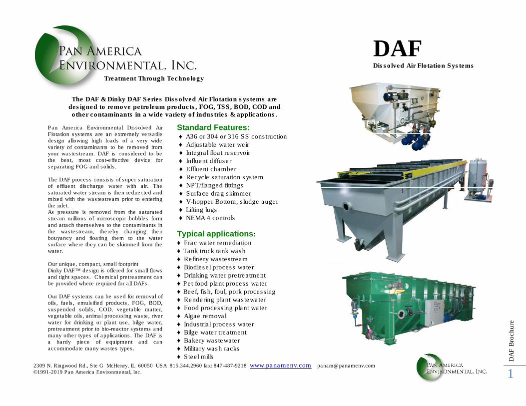
The DAF & Dinky DAF Series Dissolved Air Flotation systems are designed to remove petroleum products, FOG, TSS, BOD, COD and other contaminants in a wide variety of industries & applications.
Pan America Environmental Dissolved Air Flotation systems are an extremely versatile design allowing high loads of a very wide variety of contaminants to be removed from your wastestream. DAF is considered to be the best, most cost-effective device for separating FOG and solids. The DAF process consists of super saturation of effluent discharge water with air. The saturated water stream is then redirected and mixed with the wastestream prior to entering the inlet. As pressure is removed from the saturated stream millions of microscopic bubbles form and attach themselves to the contaminants in the wastestream, thereby changing their bouyancy and floating them to the water surface where they can be skimmed from the water. Our unique, compact, small footprint Dinky DAF™ design is offered for small flows and tight spaces. Chemical pretreatment can be provided where required for all DAFs. Our DAF systems can be used for removal of oils, fuels, emulsified products, FOG, BOD, suspended solids, COD, vegetable matter, vegetable oils, animal processing waste, river water for drinking or plant use, bilge water, pretreatment prior to bio-reactor systems and many other types of applications. The DAF is a hardy piece of equipment and can accommodate many wastes types.
Standard Features: ♦ A36 or 304 or 316 SS construction
♦ Adjustable water weir
♦ Integral float reservoir
♦ Influent diffuser
♦ Effluent chamber
♦ Recycle saturation system
♦ NPT/flanged fittings
♦ Surface drag skimmer
♦ V-hopper Bottom, sludge auger
♦ Lifting lugs
♦ NEMA 4 controls
Typical applications:
♦ Frac water remediation
♦ Tank truck tank wash
♦ Refinery wastestream
♦ Biodiesel process water
♦ Drinking water pretreatment
♦ Pet food plant process water
♦ Beef, fish, foul, pork processing
♦ Rendering plant wastewater
♦ Food processing plant water
♦ Algae removal
♦ Industrial process water
♦ Bilge water treatment
♦ Bakery wastewater
♦ Military wash racks
♦ Steel mills
Treatment Through Technology
2309 N. Ringwood Rd., Ste G McHenry, IL 60050 USA 815.344.2960 fax: 847-487-9218 www.panamenv.com [email protected] ©1991-2019 Pan America Environmental, Inc.
DA
F B
rochure
2
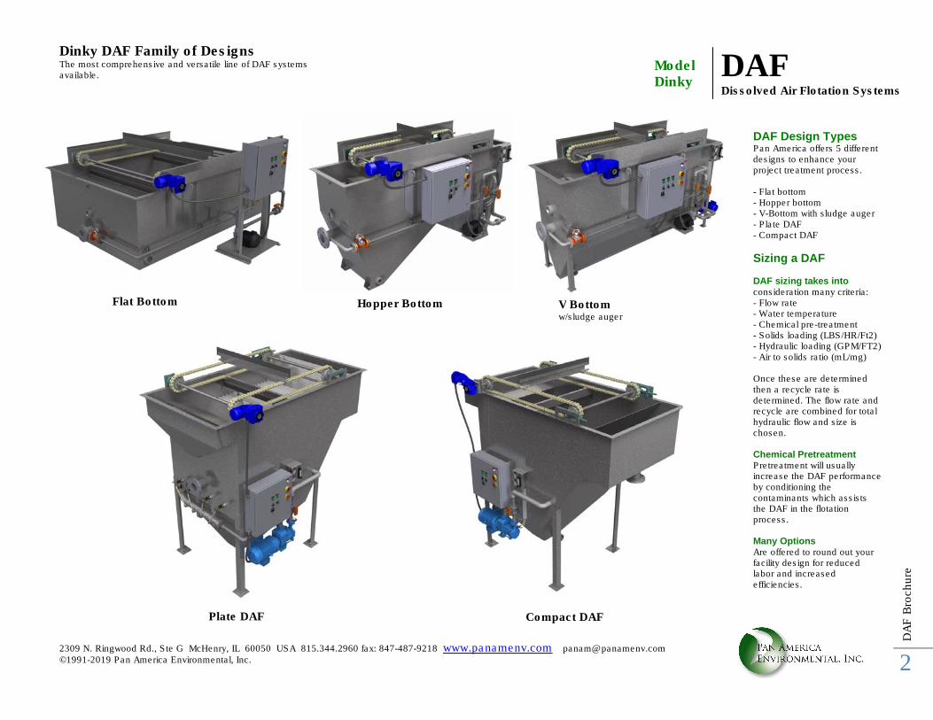
Dinky DAF Family of Designs The most comprehensive and versatile line of DAF systems available.
Model Dinky
DAF Dissolved Air Flotation Systems
Flat Bottom Hopper Bottom V Bottom w/sludge auger
Plate DAF Compact DAF
DAF Design Types Pan America offers 5 different designs to enhance your project treatment process. - Flat bottom - Hopper bottom - V-Bottom with sludge auger - Plate DAF - Compact DAF
Sizing a DAF DAF sizing takes into consideration many criteria: - Flow rate - Water temperature - Chemical pre-treatment - Solids loading (LBS/HR/Ft2) - Hydraulic loading (GPM/FT2) - Air to solids ratio (mL/mg) Once these are determined then a recycle rate is determined. The flow rate and recycle are combined for total hydraulic flow and size is chosen. Chemical Pretreatment Pretreatment will usually increase the DAF performance by conditioning the contaminants which assists the DAF in the flotation process. Many Options Are offered to round out your facility design for reduced labor and increased efficiencies.
2309 N. Ringwood Rd., Ste G McHenry, IL 60050 USA 815.344.2960 fax: 847-487-9218 www.panamenv.com [email protected] ©1991-2019 Pan America Environmental, Inc.
DA
F B
rochure
3
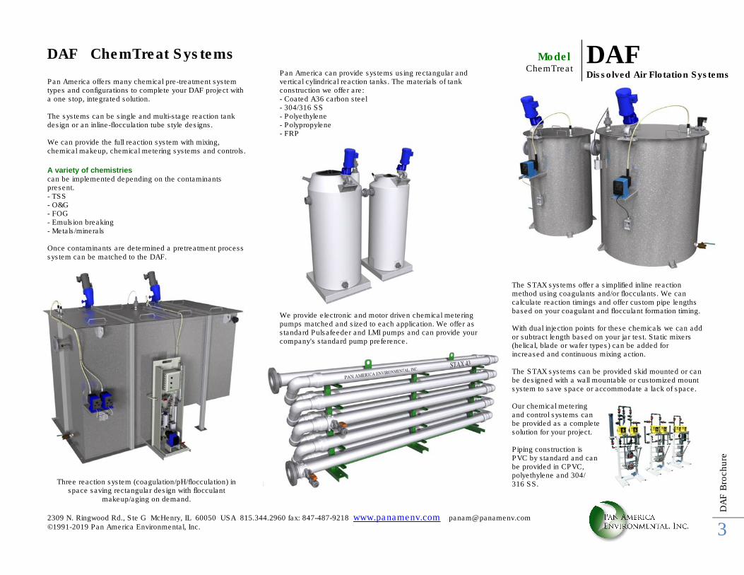
Pan America offers many chemical pre-treatment system types and configurations to complete your DAF project with a one stop, integrated solution. The systems can be single and multi-stage reaction tank design or an inline-flocculation tube style designs. We can provide the full reaction system with mixing, chemical makeup, chemical metering systems and controls.
A variety of chemistries can be implemented depending on the contaminants present. - TSS - O&G - FOG - Emulsion breaking - Metals/minerals Once contaminants are determined a pretreatment process system can be matched to the DAF.
Three reaction system (coagulation/pH/flocculation) in space saving rectangular design with flocculant
makeup/aging on demand.
Pan America can provide systems using rectangular and vertical cylindrical reaction tanks. The materials of tank construction we offer are: - Coated A36 carbon steel - 304/316 SS - Polyethylene - Polypropylene - FRP
We provide electronic and motor driven chemical metering pumps matched and sized to each application. We offer as standard Pulsafeeder and LMI pumps and can provide your company's standard pump preference.
The STAX systems offer a simplified inline reaction method using coagulants and/or flocculants. We can calculate reaction timings and offer custom pipe lengths based on your coagulant and flocculant formation timing. With dual injection points for these chemicals we can add or subtract length based on your jar test. Static mixers (helical, blade or wafer types) can be added for increased and continuous mixing action. The STAX systems can be provided skid mounted or can be designed with a wall mountable or customized mount system to save space or accommodate a lack of space. Our chemical metering and control systems can be provided as a complete solution for your project. Piping construction is PVC by standard and can be provided in CPVC, polyethylene and 304/ 316 SS.
DAF ChemTreat Systems DAF Dissolved Air Flotation Systems
Model ChemTreat
2309 N. Ringwood Rd., Ste G McHenry, IL 60050 USA 815.344.2960 fax: 847-487-9218 www.panamenv.com [email protected] ©1991-2019 Pan America Environmental, Inc.
DA
F B
rochure
4
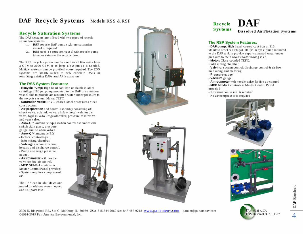
Recycle Saturation Systems The DAF systems are offered with two types of recycle saturation systems.
1. RSP recycle DAF pump style, no saturation vessel is required.
2. RSS uses a saturation vessel with recycle pump to super saturate the recycle flow.
The RSS recycle system can be used for all flow rates from 3 GPM to 2000 GPM or as large a system as is needed. Multiple systems can be provided where required. The RSS systems are ideally suited to new concrete DAFs or retrofitting existing DAFs and API separators.
The RSS System Features: - Recycle Pump: High head cast iron or stainless steel centrifugal 100 psi pump mounted to the DAF or saturation vessel skid to provide air saturated water under pressure to the recycle system. Motor: TEFC - Saturation vessel: PVC, coated steel or stainless steel construction. - Air preparation and control assembly consisting of: check valve, solenoid valve, air flow meter with needle valve, bypass valve, regulator/filter, pressure relief valve and vent valve. - Auto-Q™ automatic equalization control assembly with switch sight glass, pressure gauge and isolation valves. - Auto-Q™ automatic EQ electrical control logic. - Inlet mixing chamber. - Valving: suction isolation, bypass and discharge control. - Pump discharge pressure gauge. - Air rotameter with needle valve for fine air control. - MCP NEMA 4 controls in Master Control Panel provided. - System requires compressed air. The RSS can be shut down and turned on without system upset and EQ point loss.
The RSP System Features: - DAF pump: High head, coated cast iron or 316 stainless steel centrifugal, 100 psi recycle pump mounted to the DAF tank to provide super saturated water under pressure to the air/wastewater mixing inlet. - Motor: Close coupled TEFC. - Inlet mixing chamber - Valving: suction control, discharge control & air flow measuring and metering - Pressure gauge - Vacuum gauge - Air rotameter with needle valve for fine air control - MCP NEMA 4 controls in Master Control Panel provided - No saturation vessel is required - No air compressor is required
DAF Recycle Systems Models RSS & RSP DAF Dissolved Air Flotation Systems
Recycle Systems
2309 N. Ringwood Rd., Ste G McHenry, IL 60050 USA 815.344.2960 fax: 847-487-9218 www.panamenv.com [email protected] ©1991-2019 Pan America Environmental, Inc.
DA
F B
rochure
5
RIGHT SIDEINFLUENT END
TOP VIEW
54.00TYP.
9.21
30.00TYP.
B
A
C
D
F E
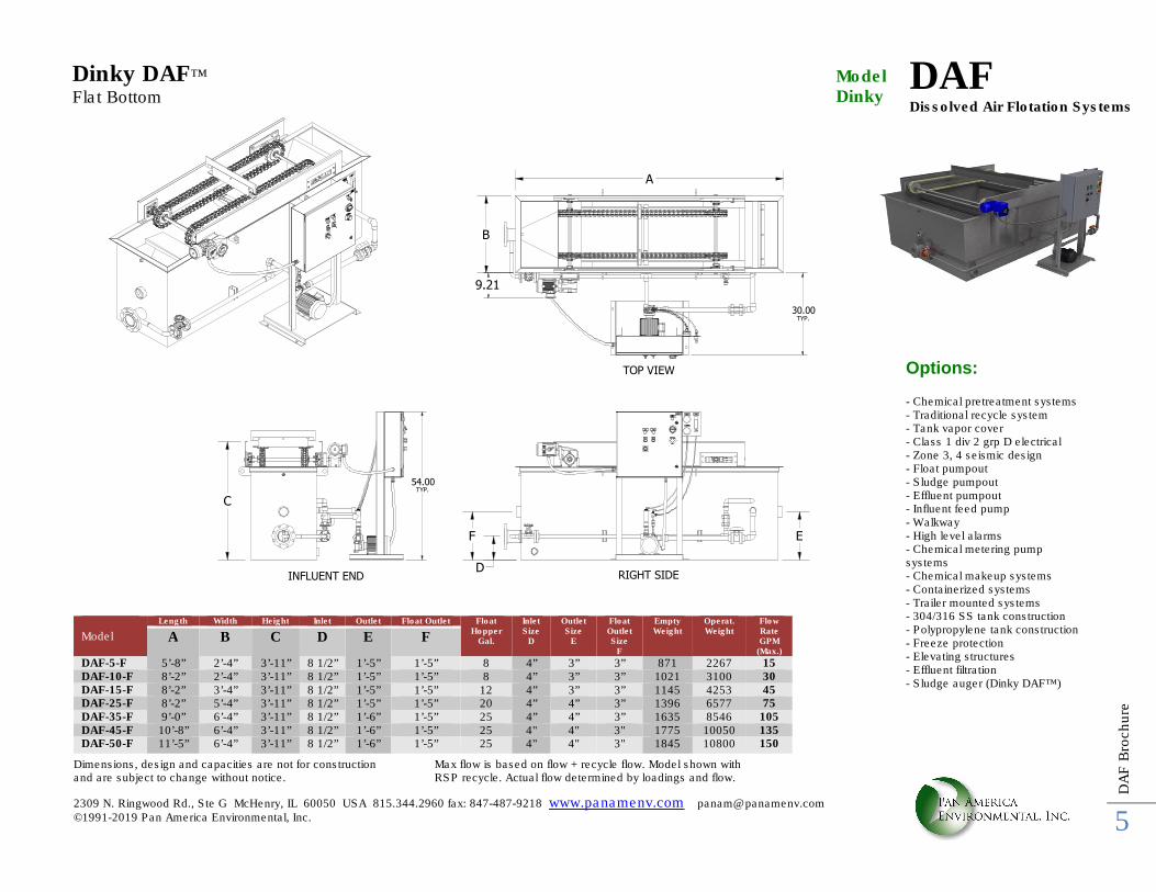
Dimensions, design and capacities are not for construction and are subject to change without notice.
Max flow is based on flow + recycle flow. Model shown with RSP recycle. Actual flow determined by loadings and flow.
Options: - Chemical pretreatment systems - Traditional recycle system - Tank vapor cover - Class 1 div 2 grp D electrical - Zone 3, 4 seismic design - Float pumpout - Sludge pumpout - Effluent pumpout - Influent feed pump - Walkway - High level alarms - Chemical metering pump systems - Chemical makeup systems - Containerized systems - Trailer mounted systems - 304/316 SS tank construction - Polypropylene tank construction - Freeze protection - Elevating structures - Effluent filtration - Sludge auger (Dinky DAF™)
Model
Length Width Height Inlet Outlet Float Outlet Float Hopper
Gal.
Inlet Size
D
Outlet Size
E
Float Outlet Size
F
Empty Weight
Operat. Weight
Flow Rate GPM
(Max.)
A B C D E F
DAF-5-F 5’-8” 2’-4” 3’-11” 8 1/2” 1’-5” 1’-5” 8 4” 3” 3” 871 2267 15 DAF-10-F 8’-2” 2’-4” 3’-11” 8 1/2” 1’-5” 1’-5” 8 4” 3” 3” 1021 3100 30 DAF-15-F 8’-2” 3’-4” 3’-11” 8 1/2” 1’-5” 1’-5” 12 4” 3” 3” 1145 4253 45 DAF-25-F 8’-2” 5’-4” 3’-11” 8 1/2” 1’-5” 1’-5” 20 4” 4” 3” 1396 6577 75 DAF-35-F 9’-0” 6’-4” 3’-11” 8 1/2” 1’-6” 1’-5” 25 4” 4” 3” 1635 8546 105 DAF-45-F 10’-8” 6’-4” 3’-11” 8 1/2” 1’-6” 1’-5” 25 4" 4" 3" 1775 10050 135 DAF-50-F 11’-5” 6’-4” 3’-11” 8 1/2” 1’-6” 1’-5” 25 4" 4" 3" 1845 10800 150
DAF Dissolved Air Flotation Systems
Model Dinky
Dinky DAF™
Flat Bottom
2309 N. Ringwood Rd., Ste G McHenry, IL 60050 USA 815.344.2960 fax: 847-487-9218 www.panamenv.com [email protected] ©1991-2019 Pan America Environmental, Inc.
DA
F B
rochure
6
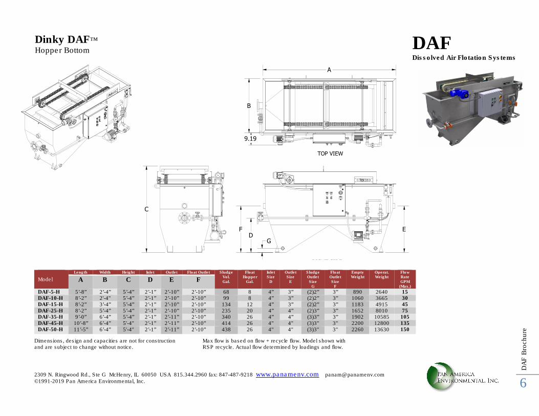
9.19
RIGHT SIDEINFLUENT END
TOP VIEW
B
A
C
D
F E
G
Dimensions, design and capacities are not for construction and are subject to change without notice.
Max flow is based on flow + recycle flow. Model shown with RSP recycle. Actual flow determined by loadings and flow.
Dinky DAF™
Hopper Bottom
Model
Length Width Height Inlet Outlet Float Outlet Sludge Vol. Gal.
Float Hopper
Gal.
Inlet Size
D
Outlet Size
E
Sludge Outlet Size
G
Float Outlet Size
F
Empty Weight
Operat. Weight
Flow Rate GPM
(Max.)
A B C D E F
DAF-5-H 5’-8” 2’-4” 5’-4” 2’-1” 2’-10” 2’-10” 68 8 4” 3” (2)2” 3” 890 2640 15 DAF-10-H 8’-2” 2'-4" 5’-4” 2’-1” 2’-10” 2’-10” 99 8 4” 3” (2)2” 3” 1060 3665 30 DAF-15-H 8’-2” 3’-4” 5’-4” 2’-1” 2’-10” 2’-10” 134 12 4” 3” (2)2” 3” 1183 4915 45 DAF-25-H 8’-2” 5’-4” 5’-4” 2’-1” 2’-10” 2’-10” 235 20 4” 4” (2)3” 3” 1652 8010 75 DAF-35-H 9’-0” 6’-4” 5’-4” 2’-1” 2’-11” 2’-10” 340 26 4” 4” (3)3” 3” 1902 10585 105 DAF-45-H 10’-8” 6’-4” 5'-4" 2’-1” 2’-11” 2’-10” 414 26 4" 4" (3)3" 3" 2200 12800 135 DAF-50-H 11’-5” 6’-4” 5'-4" 2’-1” 2’-11” 2’-10” 438 26 4" 4" (3)3" 3" 2260 13630 150
DAF Dissolved Air Flotation Systems
2309 N. Ringwood Rd., Ste G McHenry, IL 60050 USA 815.344.2960 fax: 847-487-9218 www.panamenv.com [email protected] ©1991-2019 Pan America Environmental, Inc.
DA
F B
rochure
7
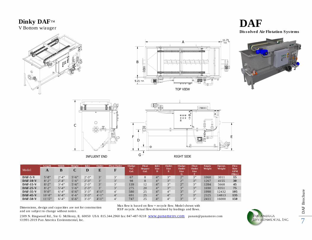
9.21 TYP.
11.71TYP.
RIGHT SIDEINFLUENT END
TOP VIEW
E
G
D
F
C
B
A
Z Dimensions, design and capacities are not for construction and are subject to change without notice.
Max flow is based on flow + recycle flow. Model shown with RSP recycle. Actual flow determined by loadings and flows.
Dinky DAF™
V Bottom w/auger
Model
Length Width Height Inlet Outlet Float Outlet Sludge Vol. Gal.
Float Hopper
Gal.
Inlet Size
D
Outlet Size
E
Sludge Outlet Size
G
Float Outlet Size
F
Empty Weight
Operat. Weight
Flow Rate GPM
(Max.)
A B C D E F
DAF-5-V 5’-8” 2’-4” 5’-6” 2’-3” 3’ 3’ 67 8 4” 3” 2” 3” 1060 3011 15 DAF-10-V 8’-2” 2'-4" 5’-6” 2’-3” 3’ 3’ 98 8 4” 3” 2” 3” 1267 4155 30 DAF-15-V 8’-2” 3’-4” 5’-6” 2’-3” 3’ 3’ 139 12 4” 3” 2” 3” 1394 5668 45 DAF-25-V 8’-2” 5’-4” 5’-6” 2’-3” 3’ 3’ 275 20 4” 3” 3” 3” 1690 8351 75 DAF-35-V 9’-0” 6’-4” 6’-6” 3’-3” 4’-1” 4’ 580 25 4” 4” 3” 3” 1990 12432 105 DAF-45-V 10’-8” 6’-4” 6'-6" 3’-3” 4’-1” 4’ 691 25 4" 4" 3" 3" 2325 14813 135 DAF-50-V 11’-5” 6’-4” 6'-6" 3’-3” 4’-1” 4’ 747 25 4" 4" 3" 3" 2411 16000 150
DAF Dissolved Air Flotation Systems
2309 N. Ringwood Rd., Ste G McHenry, IL 60050 USA 815.344.2960 fax: 847-487-9218 www.panamenv.com [email protected] ©1991-2019 Pan America Environmental, Inc.
DA
F B
rochure
8
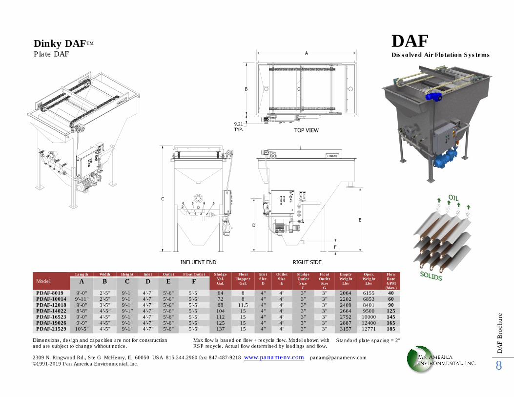
Dimensions, design and capacities are not for construction and are subject to change without notice.
Max flow is based on flow + recycle flow. Model shown with RSP recycle. Actual flow determined by loadings and flow.
Dinky DAF™
Plate DAF
Model
Length Width Height Inlet Outlet Float Outlet Sludge Vol. Gal.
Float Hopper
Gal.
Inlet Size
D
Outlet Size
E
Sludge Outlet Size
F
Float Outlet Size
G
Empty Weight
Lbs
Oper. Weight
Lbs
Flow Rate GPM
(Max.)
A B C D E F
PDAF-8019 9'-0" 2'-5" 9'-1" 4'-7" 5'-6" 5'-5" 64 8 4" 4" 3” 3” 2064 6155 40 PDAF-10014 9'-11" 2'-5" 9'-1" 4'-7" 5'-6" 5'-5" 72 8 4" 4" 3” 3” 2202 6853 60 PDAF-12018 9'-0" 3'-5" 9'-1" 4'-7" 5'-6" 5'-5" 88 11.5 4" 4" 3” 3” 2409 8401 90 PDAF-14022 8’-8” 4’-5” 9’-1” 4'-7" 5'-6" 5'-5" 104 15 4" 4" 3” 3” 2664 9500 125 PDAF-16523 9'-0" 4'-5" 9'-1" 4'-7" 5'-6" 5'-5" 112 15 4" 4" 3” 3” 2752 10000 145 PDAF-19026 9'-9" 4'-5" 9'-1" 4'-7" 5'-6" 5'-5" 125 15 4" 4" 3" 3" 2887 12400 165 PDAF-21529 10'-5" 4'-5" 9'-1" 4'-7" 5'-6" 5'-5" 137 15 4" 4" 3" 3" 3157 12771 185
DAF Dissolved Air Flotation Systems A
B
9.21
TYP.
C
D
E
F
RIGHT SIDEINFLUENT END
TOP VIEW
Standard plate spacing = 2"
2309 N. Ringwood Rd., Ste G McHenry, IL 60050 USA 815.344.2960 fax: 847-487-9218 www.panamenv.com [email protected] ©1991-2019 Pan America Environmental, Inc.
DA
F B
rochure
9
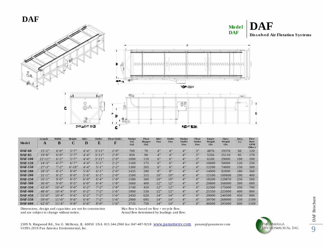
Dimensions, design and capacities are not for construction and are subject to change without notice.
Max flow is based on flow + recycle flow. Actual flow determined by loadings and flow.
Model DAF
DAF Dissolved Air Flotation Systems
Model
Length Width Height Inlet Outlet Float Outlet Sludge Vol. Gal.
Float Hopper
Gal.
Inlet Size
Outlet Size
Sludge Outlet Size
Float Outlet Size
Empty Weight
Lbs
Oper. Weight
Lbs
Area Flow Rate GPM
(Max.)
A B C D E F Ft2
DAF-60 15’-2” 6’-0” 5’-7” 4’-4” 3’-11” 2’-9” 700 70 4” 4” 4” 3” 4876 19376 60 120
DAF-85 19’-8” 6’-0” 5’-7” 4’-4” 3’-11” 2’-9” 850 90 4” 4” 4” 3” 5356 25110 85 170
DAF-100 22’-11” 6’-2” 5’-7” 4’-4” 3’-11” 2’-9” 1090 110 6” 6” 4” 3” 6100 29000 100 200
DAF-120 24’-3” 6’-7” 6’-7” 4’-4” 5’-1” 2’-2” 1160 175 6” 6” 4” 4” 10600 50000 120 250
DAF-150 27’-3” 7’-2” 6’-10” 4’-4” 5’-1” 2’-2” 1300 205 6” 6” 4” 4” 12200 74000 150 300
DAF-180 28’-3” 8’-2” 8’-0” 5’-6” 6’-1” 2’-0” 1435 280 8” 8” 4” 4” 14000 92000 180 360
DAF-200 31’-1” 8’-2” 8’-0” 5’-6” 6’-1” 2’-0” 1500 315 10” 10” 4” 4” 15100 100600 200 400
DAF-250 33’-1” 9’-0” 8’-5” 6’-0” 6’-4” 1’-8” 1580 360 10” 10” 4” 4” 18200 129870 250 500
DAF-300 36’-0” 9’-0” 8’-5” 6’-0” 6’-4” 1’-8” 1660 400 12” 12” 4” 4” 20800 166000 300 600
DAF-350 42’-0” 10’-4” 9’-0” 6’-2” 7’-2” 1’-8” 1740 450 12” 12” 4” 4” 22300 175000 350 700
DAF-400 48’-0” 10’-4” 9’-0” 6’-2” 7’-2” 1’-6” 1900 530 12” 12” 4” 4” 25350 225000 400 800
DAF-450 55’-0” 10’-4” 9’-6” 6’-2” 7’-2” 1’-6” 2450 620 14” 14” 4” 4” 29000 240500 450 900
DAF-550 59’-0” 11’-0” 9’-6” 6’-6” 7’-2” 1’-6” 2900 695 14” 14” 4” 4” 39700 268000 550 1100
DAF-600 62’-0” 11’-4” 9’-8” 6’-6” 8’-0” 1’-6” 3735 750 14” 14” 4” 4” 46000 295000 600 1500
DAF
2309 N. Ringwood Rd., Ste G McHenry, IL 60050 USA 815.344.2960 fax: 847-487-9218 www.panamenv.com [email protected] ©1991-2019 Pan America Environmental, Inc.
DA
F B
rochure
10
A
B
C
SIDE VIEW END VIEW
TOP VIEW
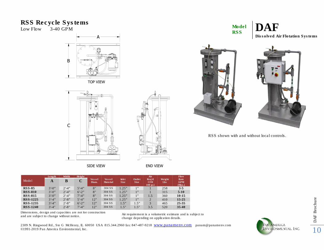
RSS Recycle Systems Low Flow 3-40 GPM Dimensions, design and capacities are not for construction and are subject to change without notice.
Air requirement is a volumetric estimate and is subject to change depending on application details.
DAF Dissolved Air Flotation Systems
Model RSS
Model
Length Width Height Vessel Diam.
Vessel
Material
Inlet Size
Outlet Size
Air Req'd CFH
100 psi
Weight
Lbs
Flow Rate GPM
(Max.)
A B C
RSS-85 3’-0” 2’-4” 5’-4” 8" 304 SS 1.25” 1” 1 258 3-5 RSS-810 3’-0” 2’-4” 6’-2” 8" 304 SS 1.25” 1” 1 315 5-10 RSS-815 3’-0” 2’-4” 7’-4” 8" 304 SS 1.25” 1” 1.5 360 10-15 RSS-1225 3’-4” 2’-8” 5’-4” 12" 304 SS 1.25” 1” 2 410 15-25 RSS-1235 3’-4” 2’-8” 6’-2” 12" 304 SS 1.5” 1.5” 3 465 25-35 RSS-1240 3'-4" 2'-8" 7’-4” 12" 304 SS 1.5" 1.5" 3.5 520 35-40
RSS shown with and without local controls.
2309 N. Ringwood Rd., Ste G McHenry, IL 60050 USA 815.344.2960 fax: 847-487-9218 www.panamenv.com [email protected] ©1991-2019 Pan America Environmental, Inc.
DA
F B
rochure
11
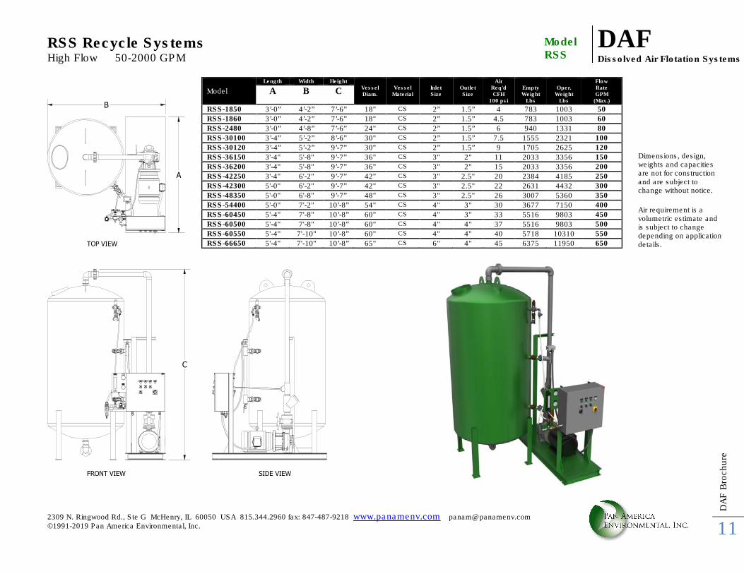
RSS Recycle Systems High Flow 50-2000 GPM
DAF Dissolved Air Flotation Systems
Model RSS
FRONT VIEW
A
B
TOP VIEW
SIDE VIEW
C
Model
Length Width Height Vessel Diam.
Vessel
Material
Inlet Size
Outlet Size
Air Req'd CFH
100 psi
Empty Weight
Lbs
Oper.
Weight Lbs
Flow Rate GPM
(Max.)
A B C
RSS-1850 3’-0” 4’-2” 7’-6” 18" CS 2” 1.5” 4 783 1003 50
RSS-1860 3’-0” 4’-2” 7’-6” 18" CS 2” 1.5” 4.5 783 1003 60
RSS-2480 3’-0” 4’-8” 7’-6” 24" CS 2” 1.5” 6 940 1331 80
RSS-30100 3’-4” 5’-2” 8’-6” 30" CS 2” 1.5” 7.5 1555 2321 100
RSS-30120 3’-4” 5’-2” 9’-7” 30" CS 2” 1.5” 9 1705 2625 120
RSS-36150 3'-4" 5'-8" 9’-7” 36" CS 3" 2" 11 2033 3356 150
RSS-36200 3'-4" 5'-8" 9’-7” 36" CS 3" 2" 15 2033 3356 200
RSS-42250 3'-4" 6'-2" 9’-7” 42" CS 3" 2.5" 20 2384 4185 250
RSS-42300 5'-0" 6'-2" 9’-7” 42" CS 3" 2.5" 22 2631 4432 300
RSS-48350 5'-0" 6'-8" 9’-7” 48" CS 3" 2.5" 26 3007 5360 350
RSS-54400 5'-0" 7'-2" 10’-8” 54" CS 4" 3" 30 3677 7150 400
RSS-60450 5'-4" 7'-8" 10’-8” 60" CS 4" 3" 33 5516 9803 450
RSS-60500 5'-4" 7'-8" 10’-8” 60" CS 4" 4" 37 5516 9803 500
RSS-60550 5'-4" 7'-10" 10’-8” 60" CS 4" 4" 40 5718 10310 550
RSS-66650 5'-4" 7'-10" 10’-8” 65" CS 6" 4" 45 6375 11950 650
Dimensions, design, weights and capacities are not for construction and are subject to change without notice. Air requirement is a volumetric estimate and is subject to change depending on application details.
2309 N. Ringwood Rd., Ste G McHenry, IL 60050 USA 815.344.2960 fax: 847-487-9218 www.panamenv.com [email protected] ©1991-2019 Pan America Environmental, Inc.
DA
F B
rochure
12
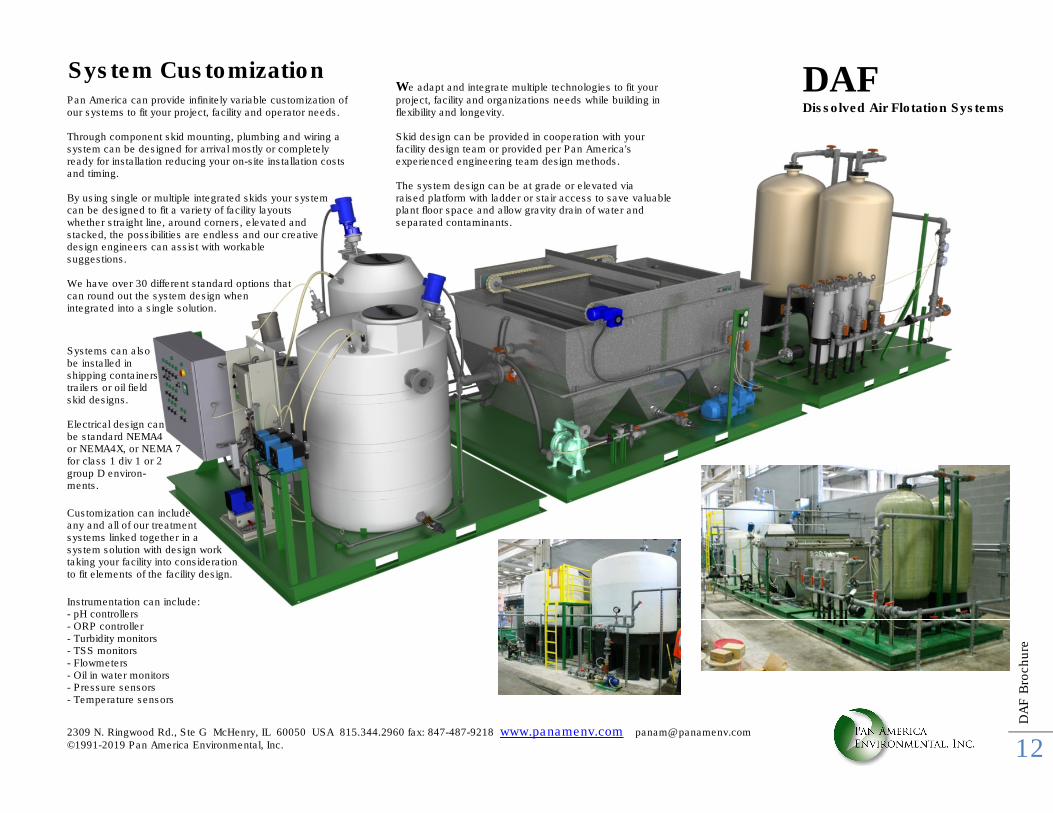
Pan America can provide infinitely variable customization of our systems to fit your project, facility and operator needs. Through component skid mounting, plumbing and wiring a system can be designed for arrival mostly or completely ready for installation reducing your on-site installation costs and timing. By using single or multiple integrated skids your system can be designed to fit a variety of facility layouts whether straight line, around corners, elevated and stacked, the possibilities are endless and our creative design engineers can assist with workable suggestions. We have over 30 different standard options that can round out the system design when integrated into a single solution.
Systems can also be installed in shipping containers trailers or oil field skid designs. Electrical design can be standard NEMA4 or NEMA4X, or NEMA 7 for class 1 div 1 or 2 group D environ- ments.
Customization can include any and all of our treatment systems linked together in a system solution with design work taking your facility into consideration to fit elements of the facility design.
Instrumentation can include: - pH controllers - ORP controller - Turbidity monitors - TSS monitors - Flowmeters - Oil in water monitors - Pressure sensors - Temperature sensors
We adapt and integrate multiple technologies to fit your project, facility and organizations needs while building in flexibility and longevity. Skid design can be provided in cooperation with your facility design team or provided per Pan America's experienced engineering team design methods. The system design can be at grade or elevated via raised platform with ladder or stair access to save valuable plant floor space and allow gravity drain of water and separated contaminants.
System Customization DAF Dissolved Air Flotation Systems
2309 N. Ringwood Rd., Ste G McHenry, IL 60050 USA 815.344.2960 fax: 847-487-9218 www.panamenv.com [email protected] ©1991-2019 Pan America Environmental, Inc.
DA
F B
rochure
13
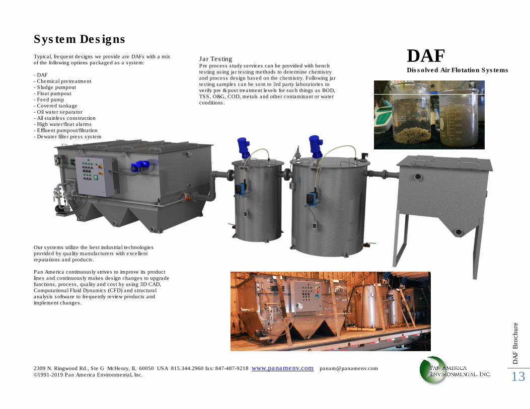
System Designs Typical, frequent designs we provide are DAFs with a mix of the following options packaged as a system: - DAF - Chemical pretreatment - Sludge pumpout - Float pumpout - Feed pump - Covered tankage - Oil water separator - All stainless construction - High water/float alarms - Effluent pumpout/filtration - Dewater filter press system Our systems utilize the best industrial technologies provided by quality manufacturers with excellent reputations and products. Pan America continuously strives to improve its product lines and continuously makes design changes to upgrade functions, process, quality and cost by using 3D CAD, Computational Fluid Dynamics (CFD) and structural analysis software to frequently review products and implement changes.
Jar Testing Pre process study services can be provided with bench testing using jar testing methods to determine chemistry and process design based on the chemistry. Following jar testing samples can be sent to 3rd party laboratories to verify pre & post treatment levels for such things as BOD, TSS, O&G, COD, metals and other contaminant or water conditions.
DAF Dissolved Air Flotation Systems
2309 N. Ringwood Rd., Ste G McHenry, IL 60050 USA 815.344.2960 fax: 847-487-9218 www.panamenv.com [email protected] ©1991-2019 Pan America Environmental, Inc.
DA
F B
rochure
14
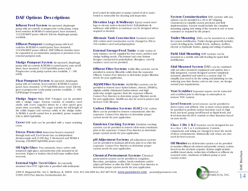
DAF Options Descriptions Influent Feed System Air operated, diaphragm
pump with air controls or progressive cavity pump, sump level switches & NEMA 4 control panel, base mounted, 115/230/460V power offered. Electric diaphragm pumps available. Effluent Pumpout Centrifugal pump with level
switches & NEMA 4 control panel, base mounted, 115/230/460V power offered. DAF Effluent chamber must be expanded to accommodate pumpout or provision of an external pumpout tank.
Sludge Pumpout System Air operated, diaphragm
pump with air controls & NEMA 4 control panel, auto on/off timer, base mounted, 115V/1ph/60Hz power req'd. Progressive cavity pump system also available. 1 - 100 GPM.
Float Pumpout System Air operated, diaphragm pump with air controls, level switches & NEMA 4 control panel, base mounted, 115V/1ph/60Hz power req'd. Electric gear or progressive cavity pump systems available. 1 - 100 GPM (larger if required)
Sludge Auger Dinky DAF V-hopper can be provided with a sludge auger. System consists of stainless steel shafts with screw auger(s) driven by a slow speed gear motor drive assembly. The auger extends the full length of the solids hopper and conveys solids to the sludge outlet. A NEMA 4 on/off control box is provided, power required: 230 or 460V/3ph/60Hz.
Cover DAF tank can be provided with a vapor retaining
cover.
Freeze Protection Immersion heaters mounted
through tank wall. Each heater has an independent thermocouple well, 0-100 deg. F thermostat and NEMA 4 housing. 230/460V/3ph/60Hz power req'd.
Oil Sight Glass Two automatic, brass valves with
tempered sight glass and protection rods mounted in oil reservoir. If glass is broken check ball stops outflow from reservoir.
External Sight / Level Glass An externally
mounted clear PVC sight tube is provided with multi-point
level switch for indication or pump control of oil or water. Switch is removable for cleaning and inspection.
Elevation Legs & Walkways Epoxy coated steel legs to elevate tank to desired level. Full platforms & walkways with ladders or stairways can be designed where required or desired.
Alternate Tank Construction Standard coated
A36 carbon steel construction can be changed to 304 or 316 stainless steel and polypropylene.
External Storage/Feed Tanks A wide variety of tank volumes can be supplied for your water, product and sludge holding needs. Flat bottom and cone bottom designs constructed in polyethylene, fiberglass, steel & stainless steel can be provided.
Effluent Filter Systems Solids filter systems can be
provided to remove filterable solids from the separator effluent. Contact Pan America to determine proper filtration needs for your application.
AQAM Filter Systems AQAM filter systems can be
provided to remove trace hydrocarbons, sheens, DNAPLs, slightly soluble chlorinated hydrocarbons and high molecular weight organics from the separator effluent. Contact Pan America to determine proper filtration needs for your application. AQAM can also be used to protect and increase GAC lifespan.
Carbon Filtration Systems (GAC) GAC carbon
filters can be provided to remove contaminants after the separator. Contact Pan America to determine proper system needs for your application. Emulsion Cracking Systems Emulsion cracking
systems can be provided to remove oil-in-water emulsions prior to the separator. Contact Pan America to determine proper system needs for your application.
pH Adjustment Systems pH adjustment systems
can be provided to maintain pH levels prior to or after the separator. Contact Pan America to determine proper system needs for your application.
Chemical Pretreatment Systems Chemical
pretreatment system can be provided to coagulate, flocculate, precipitate, oxidize, break emulsions and/or adjust pH before or after the DAF. Contact Pan America to determine proper system needs for your application.
System Containerization DAF systems with any
options can be installed in a 20 or 40’ shipping container(s) to simplify system provision and field implementation. System would include the complete mounting, piping and wiring of the system in one or more container as required by the project.
Trailer Mounting DAFs can be mounted on a trailer
for system mobilization. Trailer design generally includes corner leveling jacks, bubble levels, walkway, toolbox, electric or hydraulic brakes, piping and wiring of options.
Field Skid Mounting DAF systems can be
mounted to a mobile skid with leveling for quick field mobilization. Skid Mounted System DAFs can be combined
with our other treatment equipment and options into a fully integrated, custom designed system completely mounted, plumbed and wired to a system skid. To simplify your need to do the wiring and plumbing on site, reducing your time frames and on site costs, we design around your requirements.
Vent Scrubber Separator vapors can be extracted
and scrubbed prior to discharge to atmosphere to remove VOC content.
Level Sensors Level sensors can be provided to
detect water and oil/fuels. One or more sensor points can be provided to perform various functions such as high level, low level, pump on/off based on liquid levels and level detection for DCS controls or other functions based on your needs.
Class 1 Div 1 & 2 Systems can be designed for use
in a class 1 div 1 or 2 environment. Controls, components and wiring are changed to meet the needs of these environments. Intrinsically safe relays are also used for level sensors.
Oil Monitor an oil detection system can be provided
to monitor effluent oil content and provide various actions based on the oil alarm setpoint. Actions might include: audible/visual alarm, redirection of influent or effluent via actuated valve, shutdown of influent pump or your custom action.
2309 N. Ringwood Rd., Ste G McHenry, IL 60050 USA 815.344.2960 fax: 847-487-9218 www.panamenv.com [email protected] ©1991-2019 Pan America Environmental, Inc.
DA
F B
rochure
15
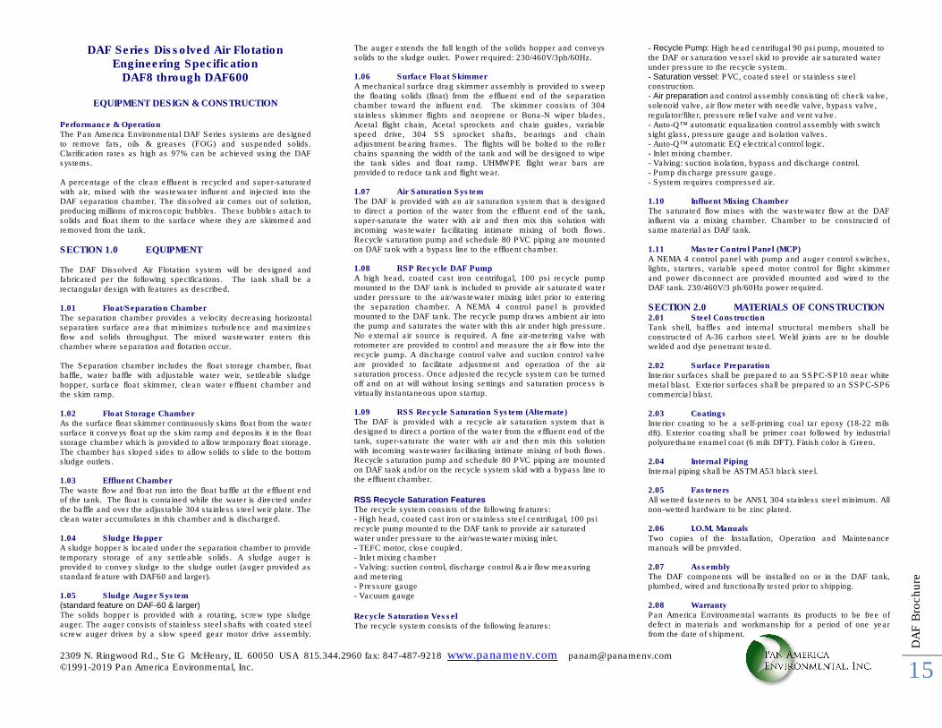
DAF Series Dissolved Air Flotation Engineering Specification
DAF8 through DAF600
EQUIPMENT DESIGN & CONSTRUCTION Performance & Operation The Pan America Environmental DAF Series systems are designed to remove fats, oils & greases (FOG) and suspended solids. Clarification rates as high as 97% can be achieved using the DAF systems. A percentage of the clean effluent is recycled and super-saturated with air, mixed with the wastewater influent and injected into the DAF separation chamber. The dissolved air comes out of solution, producing millions of microscopic bubbles. These bubbles attach to solids and float them to the surface where they are skimmed and removed from the tank.
SECTION 1.0 EQUIPMENT The DAF Dissolved Air Flotation system will be designed and fabricated per the following specifications. The tank shall be a rectangular design with features as described. 1.01 Float/Separation Chamber The separation chamber provides a velocity decreasing horizontal separation surface area that minimizes turbulence and maximizes flow and solids throughput. The mixed wastewater enters this chamber where separation and flotation occur. The Separation chamber includes the float storage chamber, float baffle, water baffle with adjustable water weir, settleable sludge hopper, surface float skimmer, clean water effluent chamber and the skim ramp. 1.02 Float Storage Chamber As the surface float skimmer continuously skims float from the water surface it conveys float up the skim ramp and deposits it in the float storage chamber which is provided to allow temporary float storage. The chamber has sloped sides to allow solids to slide to the bottom sludge outlets. 1.03 Effluent Chamber The waste flow and float run into the float baffle at the effluent end of the tank. The float is contained while the water is directed under the baffle and over the adjustable 304 stainless steel weir plate. The clean water accumulates in this chamber and is discharged. 1.04 Sludge Hopper A sludge hopper is located under the separation chamber to provide temporary storage of any settleable solids. A sludge auger is provided to convey sludge to the sludge outlet (auger provided as standard feature with DAF60 and larger). 1.05 Sludge Auger System (standard feature on DAF-60 & larger) The solids hopper is provided with a rotating, screw type sludge auger. The auger consists of stainless steel shafts with coated steel screw auger driven by a slow speed gear motor drive assembly.
The auger extends the full length of the solids hopper and conveys solids to the sludge outlet. Power required: 230/460V/3ph/60Hz. 1.06 Surface Float Skimmer A mechanical surface drag skimmer assembly is provided to sweep the floating solids (float) from the effluent end of the separation chamber toward the influent end. The skimmer consists of 304 stainless skimmer flights and neoprene or Buna-N wiper blades, Acetal flight chain, Acetal sprockets and chain guides, variable speed drive, 304 SS sprocket shafts, bearings and chain adjustment bearing frames. The flights will be bolted to the roller chains spanning the width of the tank and will be designed to wipe the tank sides and float ramp. UHMWPE flight wear bars are provided to reduce tank and flight wear. 1.07 Air Saturation System The DAF is provided with an air saturation system that is designed to direct a portion of the water from the effluent end of the tank, super-saturate the water with air and then mix this solution with incoming wastewater facilitating intimate mixing of both flows. Recycle saturation pump and schedule 80 PVC piping are mounted on DAF tank with a bypass line to the effluent chamber. 1.08 RSP Recycle DAF Pump A high head, coated cast iron centrifugal, 100 psi recycle pump mounted to the DAF tank is included to provide air saturated water under pressure to the air/wastewater mixing inlet prior to entering the separation chamber. A NEMA 4 control panel is provided mounted to the DAF tank. The recycle pump draws ambient air into the pump and saturates the water with this air under high pressure. No external air source is required. A fine air-metering valve with rotometer are provided to control and measure the air flow into the recycle pump. A discharge control valve and suction control valve are provided to facilitate adjustment and operation of the air saturation process. Once adjusted the recycle system can be turned off and on at will without losing settings and saturation process is virtually instantaneous upon startup. 1.09 RSS Recycle Saturation System (Alternate) The DAF is provided with a recycle air saturation system that is designed to direct a portion of the water from the effluent end of the tank, super-saturate the water with air and then mix this solution with incoming wastewater facilitating intimate mixing of both flows. Recycle saturation pump and schedule 80 PVC piping are mounted on DAF tank and/or on the recycle system skid with a bypass line to the effluent chamber.
RSS Recycle Saturation Features The recycle system consists of the following features: - High head, coated cast iron or stainless steel centrifugal, 100 psi recycle pump mounted to the DAF tank to provide air saturated water under pressure to the air/wastewater mixing inlet. - TEFC motor, close coupled. - Inlet mixing chamber - Valving: suction control, discharge control & air flow measuring and metering - Pressure gauge - Vacuum gauge
Recycle Saturation Vessel The recycle system consists of the following features:
- Recycle Pump: High head centrifugal 90 psi pump, mounted to the DAF or saturation vessel skid to provide air saturated water under pressure to the recycle system. - Saturation vessel: PVC, coated steel or stainless steel construction. - Air preparation and control assembly consisting of: check valve, solenoid valve, air flow meter with needle valve, bypass valve, regulator/filter, pressure relief valve and vent valve. - Auto-Q™ automatic equalization control assembly with switch sight glass, pressure gauge and isolation valves. - Auto-Q™ automatic EQ electrical control logic. - Inlet mixing chamber. - Valving: suction isolation, bypass and discharge control. - Pump discharge pressure gauge. - System requires compressed air. 1.10 Influent Mixing Chamber The saturated flow mixes with the wastewater flow at the DAF influent via a mixing chamber. Chamber to be constructed of same material as DAF tank. 1.11 Master Control Panel (MCP) A NEMA 4 control panel with pump and auger control switches, lights, starters, variable speed motor control for flight skimmer and power disconnect are provided mounted and wired to the DAF tank. 230/460V/3 ph/60Hz power required.
SECTION 2.0 MATERIALS OF CONSTRUCTION 2.01 Steel Construction Tank shell, baffles and internal structural members shall be constructed of A-36 carbon steel. Weld joints are to be double welded and dye penetrant tested. 2.02 Surface Preparation Interior surfaces shall be prepared to an SSPC-SP10 near white metal blast. Exterior surfaces shall be prepared to an SSPC-SP6 commercial blast. 2.03 Coatings Interior coating to be a self-priming coal tar epoxy (18-22 mils dft). Exterior coating shall be primer coat followed by industrial polyurethane enamel coat (6 mils DFT). Finish color is Green. 2.04 Internal Piping Internal piping shall be ASTM A53 black steel. 2.05 Fasteners All wetted fasteners to be ANSI, 304 stainless steel minimum. All non-wetted hardware to be zinc plated. 2.06 I.O.M. Manuals Two copies of the Installation, Operation and Maintenance manuals will be provided. 2.07 Assembly The DAF components will be installed on or in the DAF tank, plumbed, wired and functionally tested prior to shipping. 2.08 Warranty Pan America Environmental warrants its products to be free of defect in materials and workmanship for a period of one year from the date of shipment.
2309 N. Ringwood Rd., Ste G McHenry, IL 60050 USA 815.344.2960 fax: 847-487-9218 www.panamenv.com [email protected] ©1991-2019 Pan America Environmental, Inc.
DA
F B
rochure
16
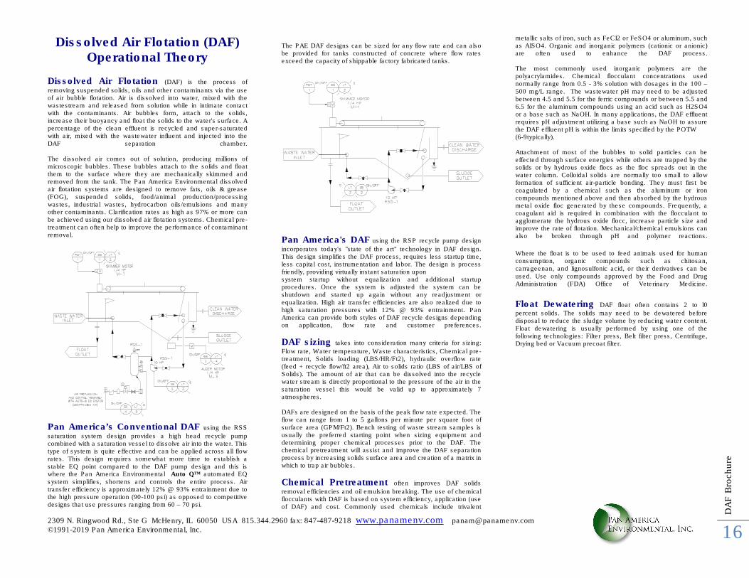
Dissolved Air Flotation (DAF) Operational Theory
Dissolved Air Flotation (DAF) is the process of
removing suspended solids, oils and other contaminants via the use of air bubble flotation. Air is dissolved into water, mixed with the wastestream and released from solution while in intimate contact with the contaminants. Air bubbles form, attach to the solids, increase their buoyancy and float the solids to the water's surface. A percentage of the clean effluent is recycled and super-saturated with air, mixed with the wastewater influent and injected into the DAF separation chamber. The dissolved air comes out of solution, producing millions of microscopic bubbles. These bubbles attach to the solids and float them to the surface where they are mechanically skimmed and removed from the tank. The Pan America Environmental dissolved air flotation systems are designed to remove fats, oils & grease (FOG), suspended solids, food/animal production/processing wastes, industrial wastes, hydrocarbon oils/emulsions and many other contaminants. Clarification rates as high as 97% or more can be achieved using our dissolved air flotation systems. Chemical pre-treatment can often help to improve the performance of contaminant removal.
Pan America’s Conventional DAF using the RSS saturation system design provides a high head recycle pump combined with a saturation vessel to dissolve air into the water. This type of system is quite effective and can be applied across all flow rates. This design requires somewhat more time to establish a stable EQ point compared to the DAF pump design and this is where the Pan America Environmental Auto Q™ automated EQ system simplifies, shortens and controls the entire process. Air transfer efficiency is approximately 12% @ 93% entrainment due to the high pressure operation (90-100 psi) as opposed to competitive designs that use pressures ranging from 60 – 70 psi.
The PAE DAF designs can be sized for any flow rate and can also be provided for tanks constructed of concrete where flow rates exceed the capacity of shippable factory fabricated tanks.
Pan America's DAF using the RSP recycle pump design
incorporates today's "state of the art" technology in DAF design. This design simplifies the DAF process, requires less startup time, less capital cost, instrumentation and labor. The design is process friendly, providing virtually instant saturation upon system startup without equalization and additional startup procedures. Once the system is adjusted the system can be shutdown and started up again without any readjustment or equalization. High air transfer efficiencies are also realized due to high saturation pressures with 12% @ 93% entrainment. Pan America can provide both styles of DAF recycle designs depending on application, flow rate and customer preferences.
DAF sizing takes into consideration many criteria for sizing:
Flow rate, Water temperature, Waste characteristics, Chemical pre-treatment, Solids loading (LBS/HR/Ft2), hydraulic overflow rate (feed + recycle flow/ft2 area), Air to solids ratio (LBS of air/LBS of Solids). The amount of air that can be dissolved into the recycle water stream is directly proportional to the pressure of the air in the saturation vessel this would be valid up to approximately 7 atmospheres. DAFs are designed on the basis of the peak flow rate expected. The flow can range from 1 to 5 gallons per minute per square foot of surface area (GPM/Ft2). Bench testing of waste stream samples is usually the preferred starting point when sizing equipment and determining proper chemical processes prior to the DAF. The chemical pretreatment will assist and improve the DAF separation process by increasing solids surface area and creation of a matrix in which to trap air bubbles.
Chemical Pretreatment often improves DAF solids
removal efficiencies and oil emulsion breaking. The use of chemical flocculants with DAF is based on system efficiency, application (use of DAF) and cost. Commonly used chemicals include trivalent
metallic salts of iron, such as FeCI2 or FeSO4 or aluminum, such as AISO4. Organic and inorganic polymers (cationic or anionic) are often used to enhance the DAF process. The most commonly used inorganic polymers are the polyacrylamides. Chemical flocculant concentrations used normally range from 0.5 - 3% solution with dosages in the 100 – 500 mg/L range. The wastewater pH may need to be adjusted between 4.5 and 5.5 for the ferric compounds or between 5.5 and 6.5 for the aluminum compounds using an acid such as H2SO4 or a base such as NaOH. In many applications, the DAF effluent requires pH adjustment utilizing a base such as NaOH to assure the DAF effluent pH is within the limits specified by the POTW (6-9typically). Attachment of most of the bubbles to solid particles can be effected through surface energies while others are trapped by the solids or by hydrous oxide flocs as the floc spreads out in the water column. Colloidal solids are normally too small to allow formation of sufficient air-particle bonding. They must first be coagulated by a chemical such as the aluminum or iron compounds mentioned above and then absorbed by the hydrous metal oxide floc generated by these compounds. Frequently, a coagulant aid is required in combination with the flocculant to agglomerate the hydrous oxide flocc, increase particle size and improve the rate of flotation. Mechanical/chemical emulsions can also be broken through pH and polymer reactions.
Where the float is to be used to feed animals used for human consumption, organic compounds such as chitosan, carrageenan, and lignosulfonic acid, or their derivatives can be used. Use only compounds approved by the Food and Drug Administration (FDA) Office of Veterinary Medicine.
Float Dewatering DAF float often contains 2 to l0
percent solids. The solids may need to be dewatered before disposal to reduce the sludge volume by reducing water content. Float dewatering is usually performed by using one of the following technologies: Filter press, Belt filter press, Centrifuge, Drying bed or Vacuum precoat filter.