Embed Size (px)
Citation preview
DA/DAC7000 SERIES — MQPILHEATER KIT INSTRUCTIONS P/N 59037 — REV. #3 (02/06/17) — PAGE 1
DA/DAC7000 Series Generators MQPILHEATERKIT
The following instructions are intended to assist the user with the installation of the in-line fuel heater on the DA/DAC7000 Series Generators. The in-line fuel heater is recommended for de-gelling fuel in cold weather starting conditions (ambient temperatures ranging at or below 32°F).
REQUIRED TOOLS
� 9/16", 10mm, 17mm Socket and 6" Extension
�Standard Screwdriver
�Phillips Screwdriver
�Needle-Nose Pliers
�Side Cutters
� Torque Wrench (35 ft-lbs./47.45 N•m)
�Wire Cutters/Strippers/Crimpers
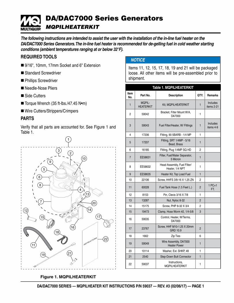
PARTS
Verify that all parts are accounted for. See Figure 1 and Table 1.
Figure 1. MQPILHEATERKIT
7
1
11
12
15
19
17
18
INSTRUCTIONS
21
22
8
6
5
910
16
14
20
23
413
NOTICE
Items 11, 12, 15, 17, 18, 19 and 21 will be packaged loose. All other items will be pre-assembled prior to shipment.
Table 1. MQPILHEATERKITItem No.
Part No. Description QTY. Remarks
1MQPIL-
HEATERKITKit, MQPILHEATERKIT 1
Includes items 2-21
2 59042Bracket, Filter Mount W/A,
DA70001
3 59043 Fuel Filter/Heater, W/ Fittings 1Includes items 4-9
4 17206 Fitting, 90 5BARB - 1/4 MP 1
5 17207Fitting, SRT 1/4MP - 5/16
Bead, Brass1
6 16185 Fitting, Plug 1/4MP SQ HD 2
7 EE58631Filter, Fuel/Water Separator,
5 Micron1
8 EE58632Head Assembly, Fuel Filter/
Heater, 1/4 NPT1
9 EE58635 Heater Kit, Top Load Fuel 1
10 22106 Screw, HHFS 3/8-16 X 1.25 ZN 2
11 60028 Fuel Tank Hose (1.5 Feet L.) 21 PC=1
FT.
12 8153 Pin, Clevis 3/16 X 7/8 1
13 13287 Nut, Nyloc 8-32 2
14 15175 Screw, PHP 8-32 X 3/4 2
15 19473 Clamp, Hose Worm #2, 1/4-5/8 3
16 59035Control, Heater, W/Terms,
DA7000
17 23767Screw, HHF M10-1.25 X 20mm
GRD 10.92
18 1662 Zip Ties 6
19 59049Wire Assembly, DA7000
Heater Power1
20 10114 Washer, Ext. SHKP, #8 1
21 2540 Step-Down Butt Connector 1
22 59037Instructions,
MQPILHEATERKIT1
DA/DAC7000 SERIES — MQPILHEATER KIT INSTRUCTIONS P/N 59037 — REV. #3 (02/06/17) — PAGE 2
WORK SAFELY!Only a qualified service technician with proper training should perform this installation. Follow all shop safety rules when performing this installation.
PREPARATION
1. Make sure generator is turned off and engine is cool.
2. Place the generator in an area free of dirt and debris and make sure it is on secure level ground. If trailer mounted, place chock blocks underneath each wheel to prevent the generator from rolling.
3. Open the battery-side door to access the fuel filter and battery.
FUEL SAFETY
DANGER
�DO NOT start the engine near spilled fuel or combustible fluids. Diesel fuel is extremely flammable and its vapors can cause an explosion if ignited.
�ALWAYS use extreme caution when working with flammable liquids.
�DO NOT smoke around or near the equipment. Fire or explosion could result from fuel vapors or if fuel is spilled on a hot engine.
BATTERY SAFETY
DANGER
�DO NOT expose the battery to open flames, sparks, cigarettes, etc. The battery contains combustible gases and liquids. If these gases or liquids come into contact with a flame or spark, an explosion could occur.
NOTICE
To prevent fuel spillage, fuel line hoses must be plugged and tied off when disconnected. Always clean up any spilled fuel immediately.
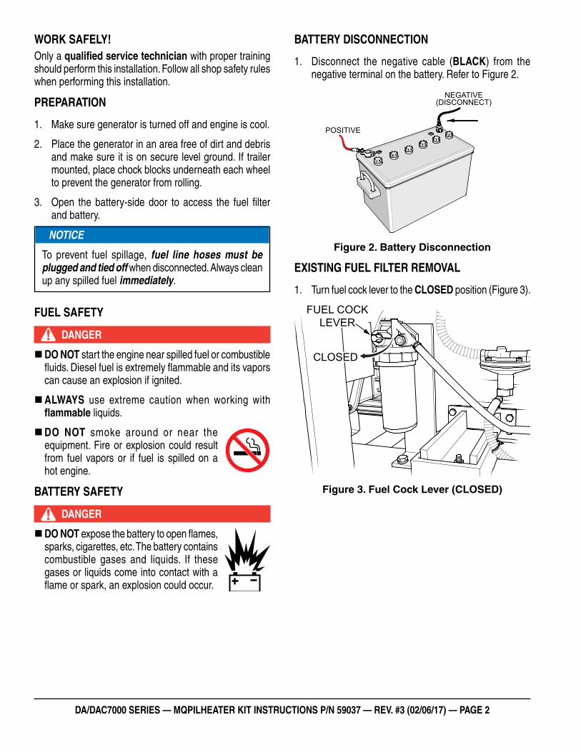
BATTERY DISCONNECTION
1. Disconnect the negative cable (BLACK) from the negative terminal on the battery. Refer to Figure 2.
Figure 2. Battery Disconnection
EXISTING FUEL FILTER REMOVAL
1. Turn fuel cock lever to the CLOSED position (Figure 3).
Figure 3. Fuel Cock Lever (CLOSED)
POSITIVE
NEGATIVE(DISCONNECT)
FUEL COCKLEVER
CLOSED
DA/DAC7000 SERIES — MQPILHEATER KIT INSTRUCTIONS P/N 59037 — REV. #3 (02/06/17) — PAGE 3
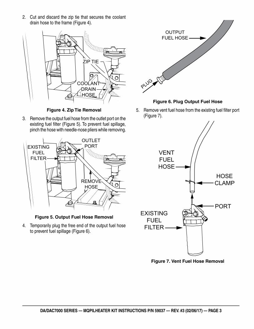
2. Cut and discard the zip tie that secures the coolant drain hose to the frame (Figure 4).
Figure 4. Zip Tie Removal
3. Remove the output fuel hose from the outlet port on the existing fuel filter (Figure 5). To prevent fuel spillage, pinch the hose with needle-nose pliers while removing.
Figure 5. Output Fuel Hose Removal
4. Temporarily plug the free end of the output fuel hose to prevent fuel spillage (Figure 6).
ZIP TIE
COOLANTDRAINHOSE
OUTLETPORT
REMOVEHOSE
EXISTINGFUEL
FILTER
Figure 6. Plug Output Fuel Hose
5. Remove vent fuel hose from the existing fuel filter port (Figure 7).
Figure 7. Vent Fuel Hose Removal
PLUG
OUTPUTFUEL HOSE
PORT
VENTFUELHOSE
EXISTINGFUEL
FILTER
HOSECLAMP
DA/DAC7000 SERIES — MQPILHEATER KIT INSTRUCTIONS P/N 59037 — REV. #3 (02/06/17) — PAGE 4
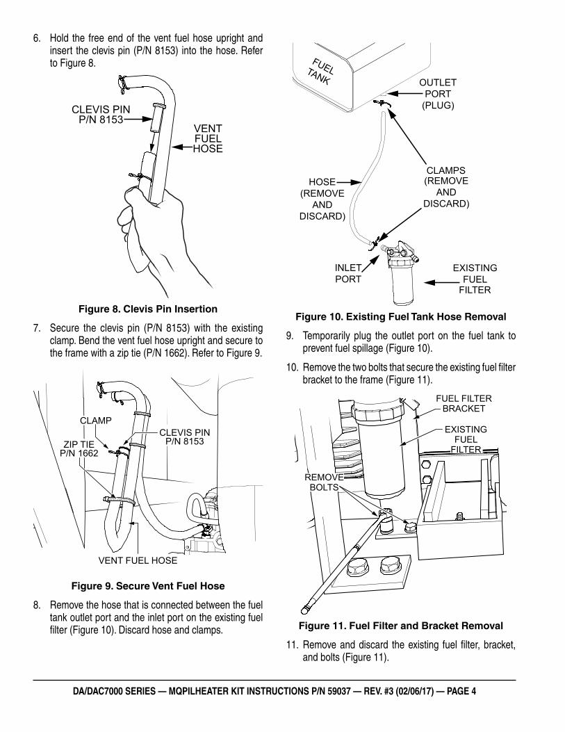
6. Hold the free end of the vent fuel hose upright and insert the clevis pin (P/N 8153) into the hose. Refer to Figure 8.
Figure 8. Clevis Pin Insertion
7. Secure the clevis pin (P/N 8153) with the existing clamp. Bend the vent fuel hose upright and secure to the frame with a zip tie (P/N 1662). Refer to Figure 9.
Figure 9. Secure Vent Fuel Hose
8. Remove the hose that is connected between the fuel tank outlet port and the inlet port on the existing fuel filter (Figure 10). Discard hose and clamps.
VENTFUELHOSE
CLEVIS PINP/N 8153
CLEVIS PINP/N 8153
CLAMP
VENT FUEL HOSE
ZIP TIEP/N 1662
Figure 10. Existing Fuel Tank Hose Removal
9. Temporarily plug the outlet port on the fuel tank to prevent fuel spillage (Figure 10).
10. Remove the two bolts that secure the existing fuel filter bracket to the frame (Figure 11).
Figure 11. Fuel Filter and Bracket Removal
11. Remove and discard the existing fuel filter, bracket, and bolts (Figure 11).
CLAMPS(REMOVE
ANDDISCARD)
EXISTINGFUEL
FILTER
INLETPORT
HOSE(REMOVE
ANDDISCARD)
OUTLETPORT
(PLUG)
FUELTANK
REMOVEBOLTS
FUEL FILTERBRACKET
EXISTINGFUEL
FILTER
DA/DAC7000 SERIES — MQPILHEATER KIT INSTRUCTIONS P/N 59037 — REV. #3 (02/06/17) — PAGE 5
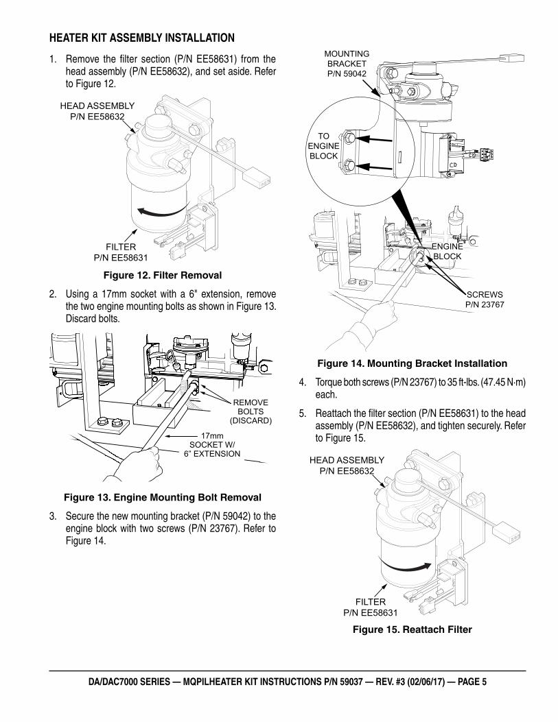
HEATER KIT ASSEMBLY INSTALLATION
1. Remove the filter section (P/N EE58631) from the head assembly (P/N EE58632), and set aside. Refer to Figure 12.
Figure 12. Filter Removal
2. Using a 17mm socket with a 6" extension, remove the two engine mounting bolts as shown in Figure 13. Discard bolts.
Figure 13. Engine Mounting Bolt Removal
3. Secure the new mounting bracket (P/N 59042) to the engine block with two screws (P/N 23767). Refer to Figure 14.
FILTERP/N EE58631
HEAD ASSEMBLYP/N EE58632
REMOVEBOLTS
(DISCARD)
17mmSOCKET W/
6” EXTENSION
Figure 14. Mounting Bracket Installation
4. Torque both screws (P/N 23767) to 35 ft-lbs. (47.45 N·m) each.
5. Reattach the filter section (P/N EE58631) to the head assembly (P/N EE58632), and tighten securely. Refer to Figure 15.
Figure 15. Reattach Filter
MOUNTINGBRACKETP/N 59042
TOENGINEBLOCK
SCREWSP/N 23767
ENGINEBLOCK
FILTERP/N EE58631
HEAD ASSEMBLYP/N EE58632
DA/DAC7000 SERIES — MQPILHEATER KIT INSTRUCTIONS P/N 59037 — REV. #3 (02/06/17) — PAGE 6
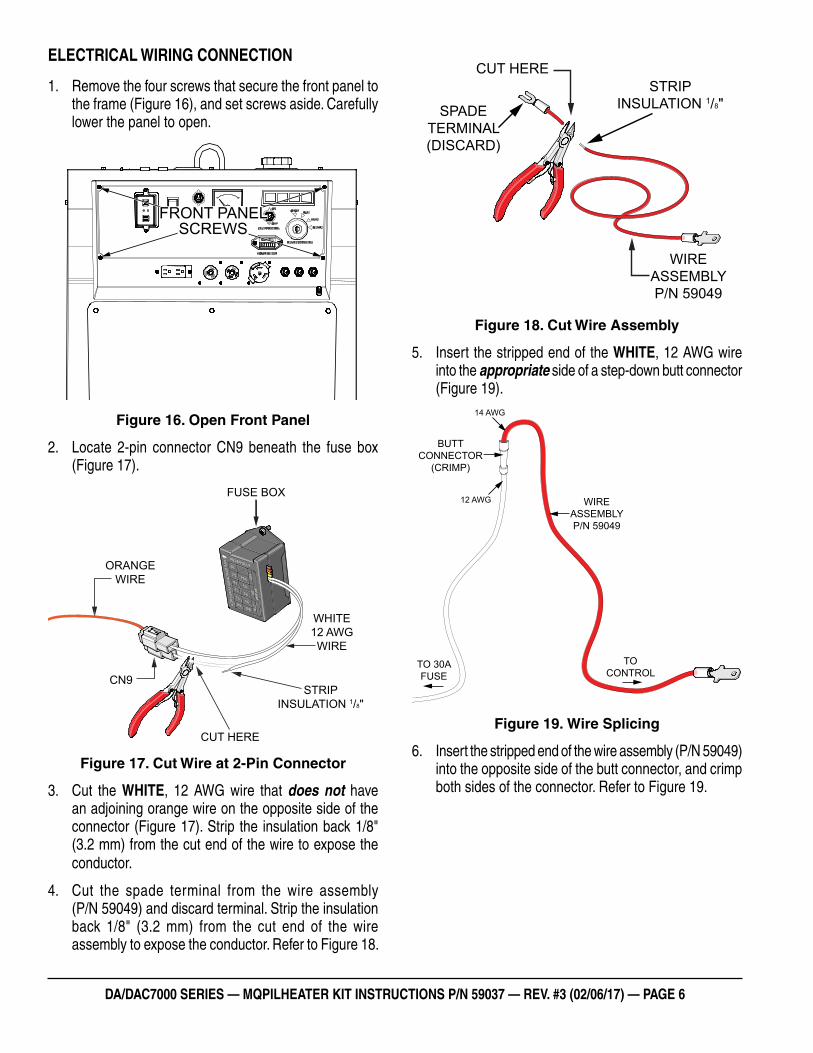
ELECTRICAL WIRING CONNECTION
1. Remove the four screws that secure the front panel to the frame (Figure 16), and set screws aside. Carefully lower the panel to open.
Figure 16. Open Front Panel
2. Locate 2-pin connector CN9 beneath the fuse box (Figure 17).
Figure 17. Cut Wire at 2-Pin Connector
3. Cut the WHITE, 12 AWG wire that does not have an adjoining orange wire on the opposite side of the connector (Figure 17). Strip the insulation back 1/8" (3.2 mm) from the cut end of the wire to expose the conductor.
4. Cut the spade terminal from the wire assembly (P/N 59049) and discard terminal. Strip the insulation back 1/8" (3.2 mm) from the cut end of the wire assembly to expose the conductor. Refer to Figure 18.
FRONT PANELSCREWS
FUSE BOX
ORANGEWIRE
CN9
WHITE12 AWGWIRE
CUT HERE
STRIPINSULATION 1/8"
Figure 18. Cut Wire Assembly
5. Insert the stripped end of the WHITE, 12 AWG wire into the appropriate side of a step-down butt connector (Figure 19).
Figure 19. Wire Splicing
6. Insert the stripped end of the wire assembly (P/N 59049) into the opposite side of the butt connector, and crimp both sides of the connector. Refer to Figure 19.
SPADETERMINAL(DISCARD)
CUT HERE
WIREASSEMBLYP/N 59049
STRIPINSULATION 1/8"
BUTTCONNECTOR
(CRIMP)
WIRE ASSEMBLYP/N 59049
TO 30AFUSE
TOCONTROL
14 AWG
12 AWG
DA/DAC7000 SERIES — MQPILHEATER KIT INSTRUCTIONS P/N 59037 — REV. #3 (02/06/17) — PAGE 7
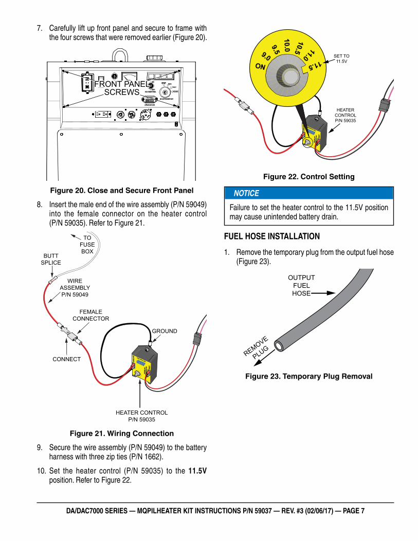
7. Carefully lift up front panel and secure to frame with the four screws that were removed earlier (Figure 20).
Figure 20. Close and Secure Front Panel
8. Insert the male end of the wire assembly (P/N 59049) into the female connector on the heater control (P/N 59035). Refer to Figure 21.
Figure 21. Wiring Connection
9. Secure the wire assembly (P/N 59049) to the battery harness with three zip ties (P/N 1662).
10. Set the heater control (P/N 59035) to the 11.5V position. Refer to Figure 22.
FRONT PANELSCREWS
WIREASSEMBLYP/N 59049
BUTTSPLICE
CONNECT
FEMALECONNECTOR
TOFUSEBOX
HEATER CONTROLP/N 59035
GROUND
Figure 22. Control Setting
FUEL HOSE INSTALLATION
1. Remove the temporary plug from the output fuel hose (Figure 23).
Figure 23. Temporary Plug Removal
HEATERCONTROLP/N 59035
SET TO11.5V
NOTICE
Failure to set the heater control to the 11.5V position may cause unintended battery drain.
REMOVE
PLUG
OUTPUTFUELHOSE
DA/DAC7000 SERIES — MQPILHEATER KIT INSTRUCTIONS P/N 59037 — REV. #3 (02/06/17) — PAGE 8
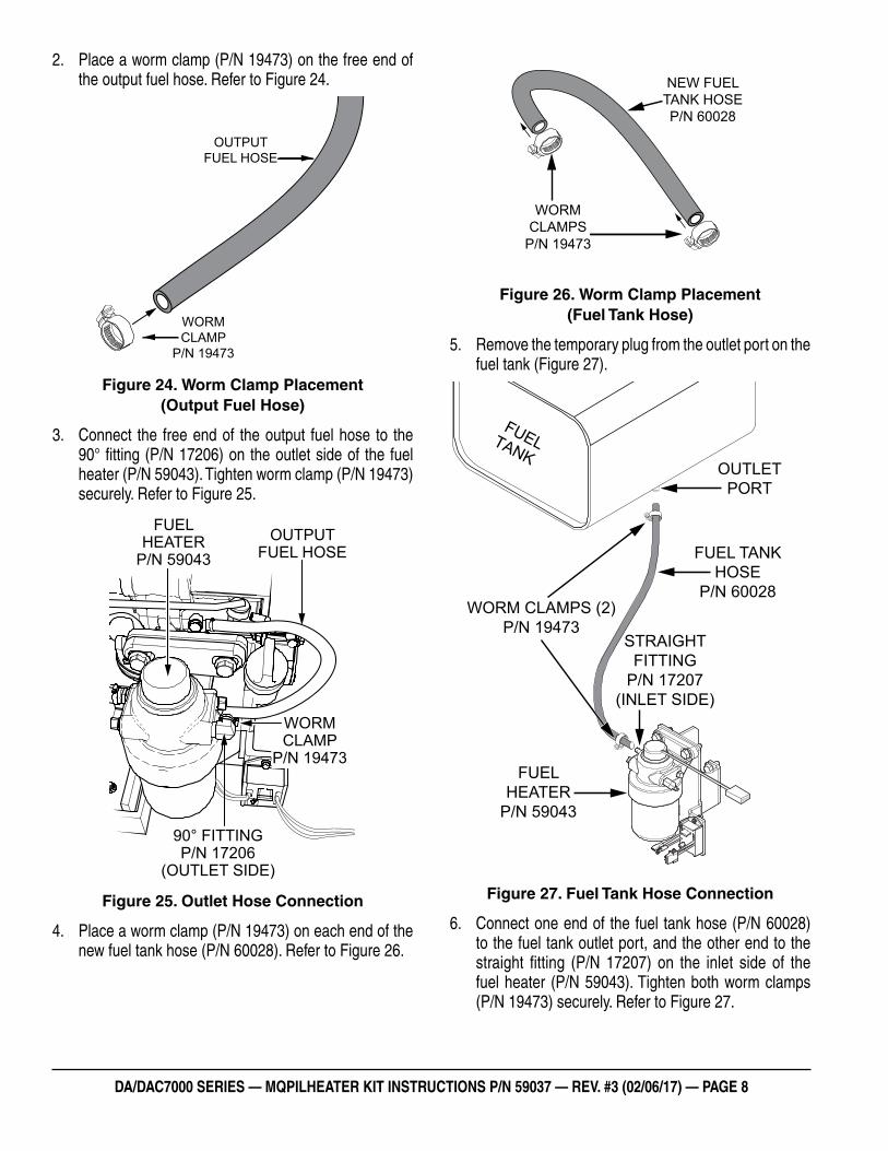
2. Place a worm clamp (P/N 19473) on the free end of the output fuel hose. Refer to Figure 24.
Figure 24. Worm Clamp Placement (Output Fuel Hose)
3. Connect the free end of the output fuel hose to the 90° fitting (P/N 17206) on the outlet side of the fuel heater (P/N 59043). Tighten worm clamp (P/N 19473) securely. Refer to Figure 25.
Figure 25. Outlet Hose Connection
4. Place a worm clamp (P/N 19473) on each end of the new fuel tank hose (P/N 60028). Refer to Figure 26.
WORMCLAMP
P/N 19473
OUTPUT FUEL HOSE
FUELHEATER
P/N 59043OUTPUT
FUEL HOSE
WORMCLAMP
P/N 19473
90° FITTINGP/N 17206
(OUTLET SIDE)
Figure 26. Worm Clamp Placement (Fuel Tank Hose)
5. Remove the temporary plug from the outlet port on the fuel tank (Figure 27).
Figure 27. Fuel Tank Hose Connection
6. Connect one end of the fuel tank hose (P/N 60028) to the fuel tank outlet port, and the other end to the straight fitting (P/N 17207) on the inlet side of the fuel heater (P/N 59043). Tighten both worm clamps (P/N 19473) securely. Refer to Figure 27.
WORMCLAMPS
P/N 19473
NEW FUEL TANK HOSEP/N 60028
FUELTANKOUTLET
PORT
FUELHEATER
P/N 59043
WORM CLAMPS (2)P/N 19473
FUEL TANKHOSE
P/N 60028
STRAIGHTFITTING
P/N 17207(INLET SIDE)
DA/DAC7000 SERIES — MQPILHEATER KIT INSTRUCTIONS P/N 59037 — REV. #3 (02/06/17) — PAGE 9
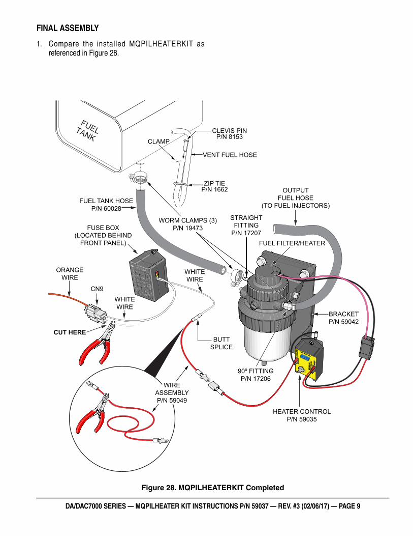
FINAL ASSEMBLY
1. Compare the installed MQPILHEATERKIT as referenced in Figure 28.
Figure 28. MQPILHEATERKIT Completed
FUELTANK
HEATER CONTROLP/N 59035
WIREASSEMBLYP/N 59049
CUT HEREBUTT
SPLICE
90º FITTINGP/N 17206
WHITEWIRE
WHITEWIRE
ORANGEWIRE
CN9
FUEL TANK HOSEP/N 60028
FUSE BOX(LOCATED BEHIND
FRONT PANEL)
WORM CLAMPS (3)P/N 19473
STRAIGHTFITTING
P/N 17207
OUTPUTFUEL HOSE
(TO FUEL INJECTORS)
FUEL FILTER/HEATER
BRACKETP/N 59042
CLEVIS PINP/N 8153
CLAMP
VENT FUEL HOSE
ZIP TIEP/N 1662
DA/DAC7000 SERIES — MQPILHEATER KIT INSTRUCTIONS P/N 59037 — REV. #3 (02/06/17) — PAGE 10
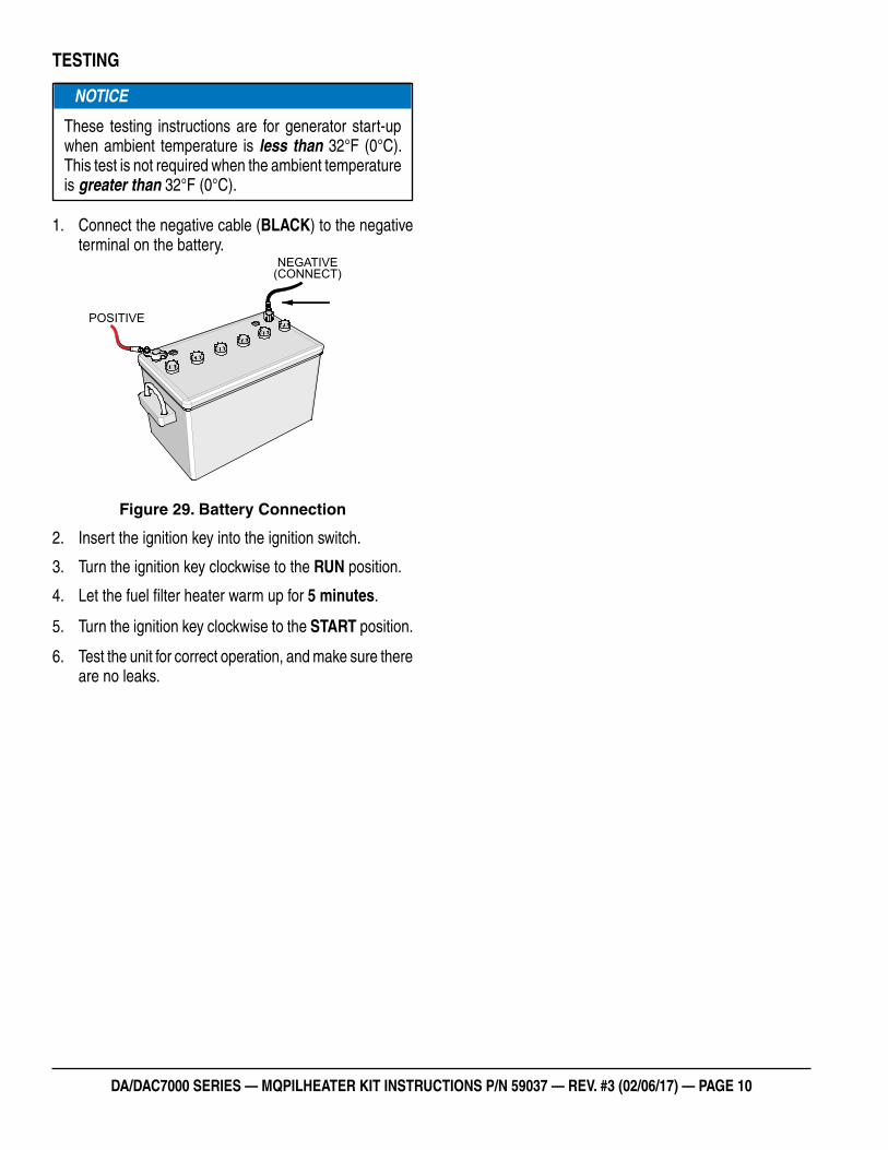
TESTING
1. Connect the negative cable (BLACK) to the negative terminal on the battery.
Figure 29. Battery Connection
2. Insert the ignition key into the ignition switch.
3. Turn the ignition key clockwise to the RUN position.
4. Let the fuel filter heater warm up for 5 minutes.
5. Turn the ignition key clockwise to the START position.
6. Test the unit for correct operation, and make sure there are no leaks.
NOTICE
These testing instructions are for generator start-up when ambient temperature is less than 32°F (0°C). This test is not required when the ambient temperature is greater than 32°F (0°C).
POSITIVE
NEGATIVE(CONNECT)
DA/DAC7000 SERIES — MQPILHEATER KIT INSTRUCTIONS P/N 59037 — REV. #3 (02/06/17) — PAGE 11
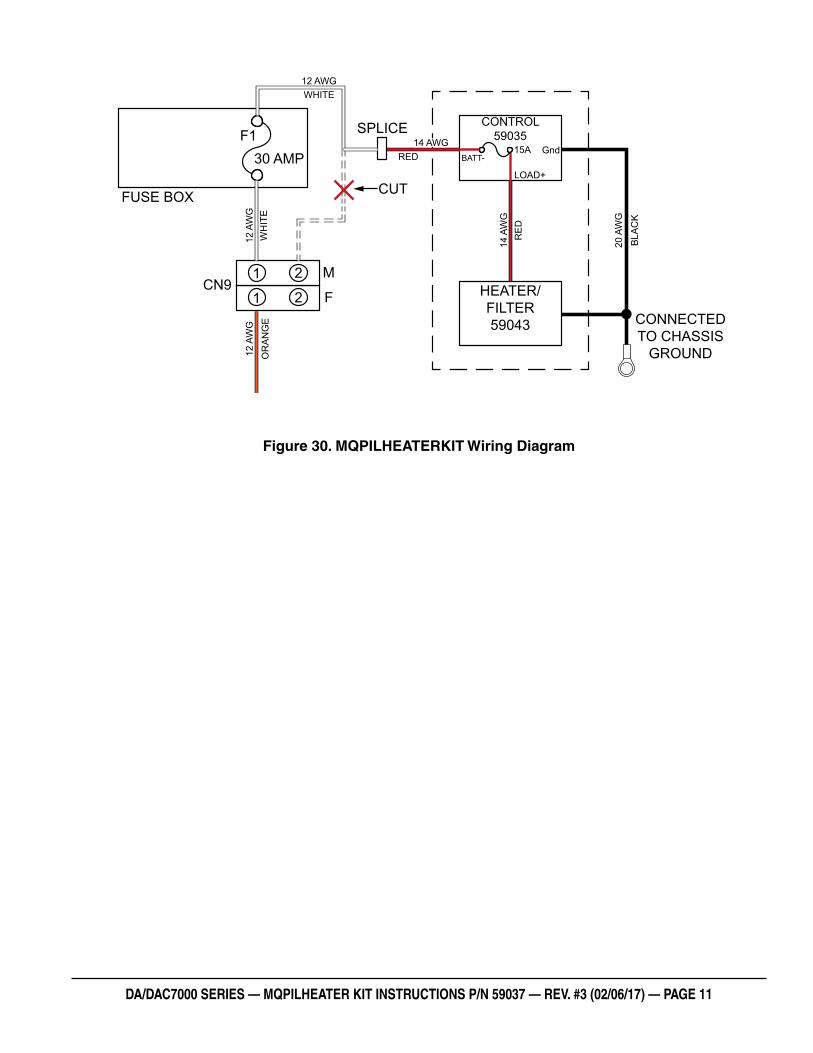
Figure 30. MQPILHEATERKIT Wiring Diagram
FUSE BOX
SPLICE
CUT
CN9
F130 AMP
M
F1
1
2
2
CONTROL59035
HEATER/FILTER59043
BATT-Gnd
LOAD+
CONNECTED TO CHASSIS
GROUND12 A
WG
OR
AN
GE
12 A
WG
WH
ITE
20 A
WG
BLA
CK
14 A
WG
RE
D
12 AWGWHITE
14 AWGRED
15A
Your Local Dealer is:
HERE’S HOW TO GET HELPPLEASE HAVE THE MODEL AND SERIAL
NUMBER ON-HAND WHEN CALLING
© COPYRIGHT 2017, MULTIQUIP INC.
Multiquip Inc , the MQ logo are registered trademarks of Multiquip Inc. and may not be used, reproduced, or altered without written permission. All other trademarks are the property of their respective owners and used with permission.
This manual MUST accompany the equipment at all times. This manual is considered a permanent part of the equipment and should remain with the unit if resold.
The information and specifi cations included in this publication were in effect at the time of approval for printing. Illustrations, descriptions, references and technical data contained in this manual are for guidance only and may not be considered as binding. Multiquip Inc. reserves the right to discontinue or change specifi cations, design or the information published in this publication at any time without notice and without incurring any obligations.
UNITED STATES Multiquip Corporate Offi ce MQ Parts Department
18910 Wilmington Ave.Carson, CA 90746 Contact : [email protected]
Tel. (800) 421-1244Fax (310) 537-3927
800-427-1244310-537-3700
Fax: 800-672-7877Fax: 310-637-3284
Service Department Warranty Department
800-421-1244310-537-3700
Fax: 310-537-4259 800-421-1244310-537-3700
Fax: 310-943-2249
Technical Assistance
800-478-1244 Fax: 310-943-2238
CANADA UNITED KINGDOM
Multiquip Multiquip (UK) Limited Head Offi ce
4110 Industriel Boul.Laval, Quebec, Canada H7L 6V3 Contact : [email protected]
Tel: (450) 625-2244Tel: (877) 963-4411Fax: (450) 625-8664
Unit 2, Northpoint Industrial Estate, Globe Lane,Dukinfi eld, Cheshire SK16 4UJ Contact : [email protected]
Tel: 0161 339 2223Fax: 0161 339 3226
DA/DAC7000 Series Generators MQPILHEATERKIT