Embed Size (px)
Citation preview
Extron Electronics, USA1230 South Lewis StreetAnaheim, CA 92805USA714.491.1500 Fax 714.491.1517
Extron Electronics, EuropeBeeldschermweg 6C3821 AH AmersfoortThe Netherlands+31.33.453.4040 Fax +31.33.453.4050
Extron Electronics, Asia135 Joo Seng Road, #04-01PM Industrial BuildingSingapore 368363+65.6383.4400 Fax +65.6383.4664
Extron Electronics, JapanKyodo Building16 IchibanchoChiyoda-ku, Tokyo 102-0082 Japan +81.3.3511.7655 Fax +81.3.3511.7656www.extron.com
© 2006 Extron Electronics. All rights reserved.
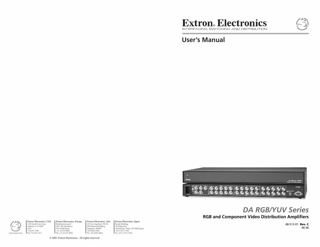
User’s Manual
RGB and Component Video Distribution Amplifi ers
68-512-01 Rev. C06 06
DA RGB/YUV Series

Precautions
This symbol is intended to alert the user of important operating and maintenance (servicing) instructions in the literature provided with the equipment.
This symbol is intended to alert the user of the presence of uninsulated dangerous voltage within the product’s enclosure that may present a risk of electric shock.
CautionRead Instructions • Read and understand all safety and operating
instructions before using the equipment. Retain Instructions • The safety instructions should be kept for future
reference.Follow Warnings • Follow all warnings and instructions marked on the
equipment or in the user information.Avoid Attachments • Do not use tools or attachments that are not
recommended by the equipment manufacturer because they may be hazardous.
WarningPower sources • This equipment should be operated only from the power source
indicated on the product. This equipment is intended to be used with a main power system with a grounded (neutral) conductor. The third (grounding) pin is a safety feature, do not attempt to bypass or disable it.
Power disconnection • To remove power from the equipment safely, remove all power cords from the rear of the equipment, or the desktop power module (if detachable), or from the power source receptacle (wall plug).
Power cord protection • Power cords should be routed so that they are not likely to be stepped on or pinched by items placed upon or against them.
Servicing • Refer all servicing to qualifi ed service personnel. There are no user-serviceable parts inside. To prevent the risk of shock, do not attempt to service this equipment yourself because opening or removing covers may expose you to dangerous voltage or other hazards.
Slots and openings • If the equipment has slots or holes in the enclosure, these are provided to prevent overheating of sensitive components inside. These openings must never be blocked by other objects.
Lithium battery • There is a danger of explosion if battery is incorrectly replaced. Replace it only with the same or equivalent type recommended by the manufacturer. Dispose of used batteries according to the manufacturer’s instructions.
Ce symbole sert à avertir l’utilisateur que la documentation fournie avec le matériel contient des instructions importantes concernant l’exploitation et la maintenance (réparation).
Ce symbole sert à avertir l’utilisateur de la présence dans le boîtier de l’appareil de tensions dangereuses non isolées posant des risques d’électrocution.
AttentionLire les instructions• Prendre connaissance de toutes les consignes de
sécurité et d’exploitation avant d’utiliser le matériel.Conserver les instructions• Ranger les consignes de sécurité afi n de pouvoir
les consulter à l’avenir.Respecter les avertissements • Observer tous les avertissements et consignes
marqués sur le matériel ou présentés dans la documentation utilisateur.Eviter les pièces de fi xation • Ne pas utiliser de pièces de fi xation ni d’outils
non recommandés par le fabricant du matériel car cela risquerait de poser certains dangers.
AvertissementAlimentations• Ne faire fonctionner ce matériel qu’avec la source d’alimentation
indiquée sur l’appareil. Ce matériel doit être utilisé avec une alimentation principale comportant un fi l de terre (neutre). Le troisième contact (de mise à la terre) constitue un dispositif de sécurité : n’essayez pas de la contourner ni de la désactiver.
Déconnexion de l’alimentation• Pour mettre le matériel hors tension sans danger, déconnectez tous les cordons d’alimentation de l’arrière de l’appareil ou du module d’alimentation de bureau (s’il est amovible) ou encore de la prise secteur.
Protection du cordon d’alimentation • Acheminer les cordons d’alimentation de manière à ce que personne ne risque de marcher dessus et à ce qu’ils ne soient pas écrasés ou pincés par des objets.
Réparation-maintenance • Faire exécuter toutes les interventions de réparation-maintenance par un technicien qualifi é. Aucun des éléments internes ne peut être réparé par l’utilisateur. Afi n d’éviter tout danger d’électrocution, l’utilisateur ne doit pas essayer de procéder lui-même à ces opérations car l’ouverture ou le retrait des couvercles risquent de l’exposer à de hautes tensions et autres dangers.
Fentes et orifi ces • Si le boîtier de l’appareil comporte des fentes ou des orifi ces, ceux-ci servent à empêcher les composants internes sensibles de surchauffer. Ces ouvertures ne doivent jamais être bloquées par des objets.
Lithium Batterie • Il a danger d’explosion s’ll y a remplacment incorrect de la batterie. Remplacer uniquement avec une batterie du meme type ou d’un ype equivalent recommande par le constructeur. Mettre au reut les batteries usagees conformement aux instructions du fabricant.
Safety Instructions • English
Consignes de Sécurité • Français
Sicherheitsanleitungen • DeutschDieses Symbol soll dem Benutzer in der im Lieferumfang enthaltenen Dokumentation besonders wichtige Hinweise zur Bedienung und Wartung (Instandhaltung) geben.
Dieses Symbol soll den Benutzer darauf aufmerksam machen, daß im Inneren des Gehäuses dieses Produktes gefährliche Spannungen, die nicht isoliert sind und die einen elektrischen Schock verursachen können, herrschen.
AchtungLesen der Anleitungen • Bevor Sie das Gerät zum ersten Mal verwenden,
sollten Sie alle Sicherheits-und Bedienungsanleitungen genau durchlesen und verstehen.
Aufbewahren der Anleitungen • Die Hinweise zur elektrischen Sicherheit des Produktes sollten Sie aufbewahren, damit Sie im Bedarfsfall darauf zurückgreifen können.
Befolgen der Warnhinweise • Befolgen Sie alle Warnhinweise und Anleitungen auf dem Gerät oder in der Benutzerdokumentation.
Keine Zusatzgeräte • Verwenden Sie keine Werkzeuge oder Zusatzgeräte, die nicht ausdrücklich vom Hersteller empfohlen wurden, da diese eine Gefahrenquelle darstellen können.
VorsichtStromquellen • Dieses Gerät sollte nur über die auf dem Produkt angegebene
Stromquelle betrieben werden. Dieses Gerät wurde für eine Verwendung mit einer Hauptstromleitung mit einem geerdeten (neutralen) Leiter konzipiert. Der dritte Kontakt ist für einen Erdanschluß, und stellt eine Sicherheitsfunktion dar. Diese sollte nicht umgangen oder außer Betrieb gesetzt werden.
Stromunterbrechung • Um das Gerät auf sichere Weise vom Netz zu trennen, sollten Sie alle Netzkabel aus der Rückseite des Gerätes, aus der externen Stomversorgung (falls dies möglich ist) oder aus der Wandsteckdose ziehen.
Schutz des Netzkabels • Netzkabel sollten stets so verlegt werden, daß sie nicht im Weg liegen und niemand darauf treten kann oder Objekte darauf- oder unmittelbar dagegengestellt werden können.
Wartung • Alle Wartungsmaßnahmen sollten nur von qualifi ziertem Servicepersonal durchgeführt werden. Die internen Komponenten des Gerätes sind wartungsfrei. Zur Vermeidung eines elektrischen Schocks versuchen Sie in keinem Fall, dieses Gerät selbst öffnen, da beim Entfernen der Abdeckungen die Gefahr eines elektrischen Schlags und/oder andere Gefahren bestehen.
Schlitze und Öffnungen • Wenn das Gerät Schlitze oder Löcher im Gehäuse aufweist, dienen diese zur Vermeidung einer Überhitzung der empfi ndlichen Teile im Inneren. Diese Öffnungen dürfen niemals von anderen Objekten blockiert werden.
Litium-Batterie • Explosionsgefahr, falls die Batterie nicht richtig ersetzt wird. Ersetzen Sie verbrauchte Batterien nur durch den gleichen oder einen vergleichbaren Batterietyp, der auch vom Hersteller empfohlen wird. Entsorgen Sie verbrauchte Batterien bitte gemäß den Herstelleranweisungen.
Este símbolo se utiliza para advertir al usuario sobre instrucciones importantes de operación y mantenimiento (o cambio de partes) que se desean destacar en el contenido de la documentación suministrada con los equipos.
Este símbolo se utiliza para advertir al usuario sobre la presencia de elementos con voltaje peligroso sin protección aislante, que puedan encontrarse dentro de la caja o alojamiento del producto, y que puedan representar riesgo de electrocución.
PrecaucionLeer las instrucciones • Leer y analizar todas las instrucciones de operación y
seguridad, antes de usar el equipo.Conservar las instrucciones • Conservar las instrucciones de seguridad para
futura consulta.Obedecer las advertencias • Todas las advertencias e instrucciones marcadas
en el equipo o en la documentación del usuario, deben ser obedecidas.Evitar el uso de accesorios • No usar herramientas o accesorios que no
sean especifi camente recomendados por el fabricante, ya que podrian implicar riesgos.
AdvertenciaAlimentación eléctrica • Este equipo debe conectarse únicamente a la fuente/tipo
de alimentación eléctrica indicada en el mismo. La alimentación eléctrica de este equipo debe provenir de un sistema de distribución general con conductor neutro a tierra. La tercera pata (puesta a tierra) es una medida de seguridad, no puentearia ni eliminaria.
Desconexión de alimentación eléctrica • Para desconectar con seguridad la acometida de alimentación eléctrica al equipo, desenchufar todos los cables de alimentación en el panel trasero del equipo, o desenchufar el módulo de alimentación (si fuera independiente), o desenchufar el cable del receptáculo de la pared.
Protección del cables de alimentación • Los cables de alimentación eléctrica se deben instalar en lugares donde no sean pisados ni apretados por objetos que se puedan apoyar sobre ellos.
Reparaciones/mantenimiento • Solicitar siempre los servicios técnicos de personal califi cado. En el interior no hay partes a las que el usuario deba acceder. Para evitar riesgo de electrocución, no intentar personalmente la reparación/mantenimiento de este equipo, ya que al abrir o extraer las tapas puede quedar expuesto a voltajes peligrosos u otros riesgos.
Ranuras y aberturas • Si el equipo posee ranuras o orifi cios en su caja/alojamiento, es para evitar el sobrecalientamiento de componentes internos sensibles. Estas aberturas nunca se deben obstruir con otros objetos.
Batería de litio • Existe riesgo de explosión si esta batería se coloca en la posición incorrecta. Cambiar esta batería únicamente con el mismo tipo (o su equivalente) recomendado por el fabricante. Desachar las baterías usadas siguiendo las instrucciones del fabricante.
Instrucciones de seguridad • Español
FCC Class A NoticeNote: This equipment has been tested and found to comply with the limits for a Class A digital device, pursuant to part 15 of the FCC Rules. These limits are designed to provide reasonable protection against harmful interference when the equipment is operated in a commercial environment. This equipment generates, uses and can radiate radio frequency energy and, if not installed and used in accordance with the instruction manual, may cause harmful interference to radio communications. Operation of this equipment in a residential area is likely to cause harmful interference, in which case the user will be required to correct the interference at his own expense.
Note: These units was tested with shielded cables on the peripheral devices and between the transmitter and receiver. Shielded cables must be used with the units to ensure compliance.
Extron’s WarrantyExtron Electronics warrants this product against defects in materials and workmanship for a period of three years from the date of purchase. In the event of malfunction during the warranty period attributable directly to faulty workmanship and/or materials, Extron Electronics will, at its option, repair or replace said products or components, to whatever extent it shall deem necessary to restore said product to proper operating condition, provided that it is returned within the warranty period, with proof of purchase and description of malfunction to:
USA, Canada, South America, Europe, Africa, and the Middle East: and Central America: Extron Electronics, Europe Extron Electronics Beeldschermweg 6C 1001 East Ball Road 3821 AH Amersfoort Anaheim, CA 92805, USA The Netherlands
Asia: Japan: Extron Electronics, Asia Extron Electronics, Japan 135 Joo Seng Road, #04-01 Kyodo Building PM Industrial Bldg. 16 Ichibancho Singapore 368363 Chiyoda-ku, Tokyo 102-0082 Japan
This Limited Warranty does not apply if the fault has been caused by misuse, improper handling care, electrical or mechanical abuse, abnormal operating conditions or non-Extron authorized modifi cation to the product.
If it has been determined that the product is defective, please call Extron and ask for an Applications Engineer at (714) 491-1500 (USA), 31.33.453.4040 (Europe), 65.6383.4400 (Asia), or 81.3.3511.7655 (Japan) to receive an RA# (Return Authorization number). This will begin the repair process as quickly as possible.
Units must be returned insured, with shipping charges prepaid. If not insured, you assume the risk of loss or damage during shipment. Returned units must include the serial number and a description of the problem, as well as the name of the person to contact in case there are any questions.
Extron Electronics makes no further warranties either expressed or implied with respect to the product and its quality, performance, merchantability, or fi tness for any particular use. In no event will Extron Electronics be liable for direct, indirect, or consequential damages resulting from any defect in this product even if Extron Electronics has been advised of such damage.
Please note that laws vary from state to state and country to country, and that some provisions of this warranty may not apply to you.
DA RGB/YUV Distribution Amplifiers • Quick Start Guide
Quick Start Guide — DA RGB/YUV
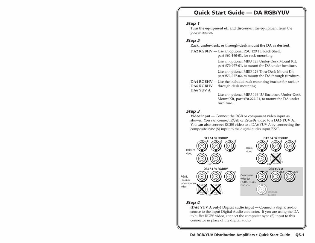
Step 1Turn the equipment off and disconnect the equipment from thepower source.
Step 2Rack, under-desk, or through-desk mount the DA as desired.
DA2 RGBHV — Use an optional RSU 129 1U Rack Shelf,part #60-190-01, for rack mounting.
Use an optional MBU 125 Under-Desk Mount Kit,part #70-077-01, to mount the DA under furniture.
Use an optional MBD 129 Thru-Desk Mount Kit,part #70-077-02, to mount the DA through furniture.
DA4 RGBHV — Use the included rack mounting bracket for rack orDA6 RGBHV through-desk mounting.DA6 YUV A
Use an optional MBU 149 1U Enclosure Under-DeskMount Kit, part #70-222-01, to mount the DA underfurniture.
Step 3Video input — Connect the RGB or component video input asshown. You can connect RGsB or RsGsBs video to a DA6 YUV A.You can also connect RGBS video to a DA6 YUV A by connecting thecomposite sync (S) input to the digital audio input BNC.
Step 4(DA6 YUV A only) Digital audio input — Connect a digital audiosource to the input Digital Audio connector. If you are using the DAto buffer RGBS video, connect the composite sync (S) input to thisconnector in place of the digital audio.
RGBHVvideo
RGBSvideo
RGsB,RsGsBs(or componentvideo)
Componentvideo (orRGBS, RGsB,RsGsBs
DA6 YUV A
R
HH/V
G
V
B R
HH/V
G
V
B
R
HH/V
G
V
B Y
DA2 / 4 / 6 RGBHV DA2 / 4 / 6 RGBHV
DA2 / 4 / 6 RGBHVR-Y B-Y
DIGITALAUDIO
QS-1
DA RGB/YUV Distribution Amplifiers • Quick Start Guide
Quick Start Guide — DA RGB/YUV, cont’d
iDA RGB/YUV Distribution Amplifiers • Table of Contents
Chapter 1 • Introduction .......................................................... 1-1
About the Distribution Amplifiers ............................... 1-2
Chapter 2 • Installation and Operation ......................... 2-1
Installation Overview .......................................................... 2-2
Mounting Options ................................................................. 2-2Rack mounting the DA ............................................................. 2-2
Rack mounting the DA2 .................................................... 2-2Rack mounting the DA4 and DA6 ...................................... 2-4
Under-furniture mounting the DA ......................................... 2-4Through-furniture mounting the DA................................... 2-6
Rear Panel Connections ...................................................... 2-7Input connections .................................................................. 2-8Output connections ............................................................... 2-9Mute connection ................................................................. 2-10Power connection ................................................................ 2-10
Controls and Indicators .................................................... 2-11
Operation and Troubleshooting .................................. 2-12If the image does not appear or is not displayed correctly . 2-12
Appendix A • Reference Information ............................ A-1
Specifications ......................................................................... A-2
Part Numbers .......................................................................... A-6DA part numbers .................................................................. A-6Included parts ....................................................................... A-6Optional accessories ............................................................. A-6Bulk cable .............................................................................. A-6Assorted connectors ............................................................. A-7Pre-cut cables ........................................................................ A-7
Table of Contents
68-512-01 Rev. C06 06
All trademarks mentioned in this manual are the properties of their respective owners.
RGBHVvideo
RGBSvideo
RGsB,RsGsBs(or componentvideo)
Componentvideo (orRGBS, RGsB,RsGsBs
DA6 YUV A
DA2 RGBHV, DA4 RGBHV, DA6 RGBHVHH/V
VR G B
HH/V
VR G B
HH/V
VR G B
DIGITALAUDIOY R-Y B-Y
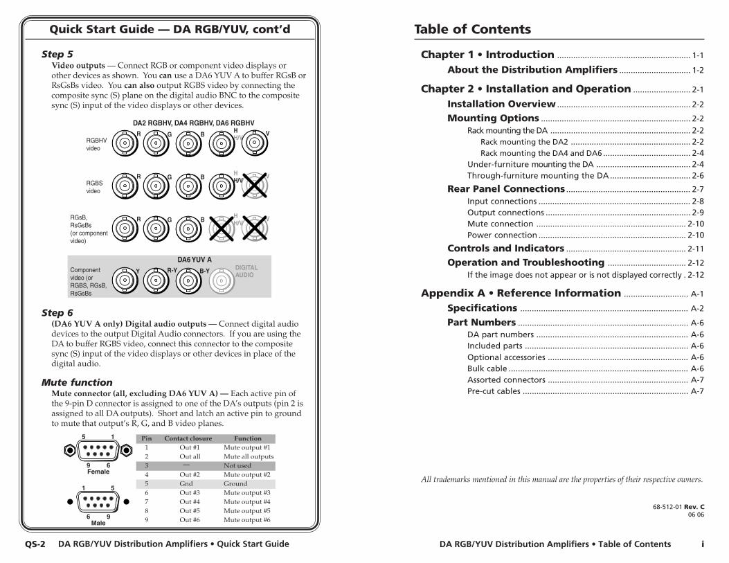
Step 5Video outputs — Connect RGB or component video displays orother devices as shown. You can use a DA6 YUV A to buffer RGsB orRsGsBs video. You can also output RGBS video by connecting thecomposite sync (S) plane on the digital audio BNC to the compositesync (S) input of the video displays or other devices.
Step 6(DA6 YUV A only) Digital audio outputs — Connect digital audiodevices to the output Digital Audio connectors. If you are using theDA to buffer RGBS video, connect this connector to the compositesync (S) input of the video displays or other devices in place of thedigital audio.
Mute functionMute connector (all, excluding DA6 YUV A) — Each active pin ofthe 9-pin D connector is assigned to one of the DA’s outputs (pin 2 isassigned to all DA outputs). Short and latch an active pin to groundto mute that output’s R, G, and B video planes.
Pin Contact closure Function1 Out #1 Mute output #12
—Out all Mute all outputs
3 Not used4 Out #2 Mute output #25 Gnd Ground6 Out #3
Out #4Out #5Out #6
Mute output #3
Mute output #6
Mute output #4Mute output #5
789
Female
5 1
9 6
Male
1 5
6 9
QS-2
ii DA RGB/YUV Distribution Amplifiers • Table of Contents
Table of Contents, cont’d
DA RGB/YUV Distribution Amplifiers
1Chapter One
Introduction
About the Distribution Amplifiers
DA RGB/YUV Distribution Amplifiers • Introduction
Introduction
DA RGB/YUV Distribution Amplifiers
2Chapter Two
Installation and Operation
Installation Overview
Mounting Options
Rear Panel Connections
Controls and Indicators
Operation and Troubleshooting
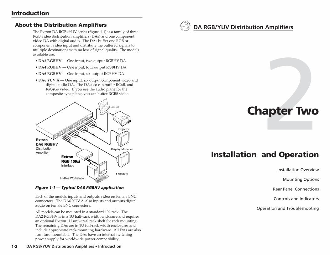
About the Distribution AmplifiersThe Extron DA RGB/YUV series (figure 1-1) is a family of threeRGB video distribution amplifiers (DAs) and one componentvideo DA with digital audio. The DAs buffer one RGB orcomponent video input and distribute the buffered signals tomultiple destinations with no loss of signal quality. The modelsavailable are:
• DA2 RGBHV — One input, two output RGBHV DA
• DA4 RGBHV — One input, four output RGBHV DA
• DA6 RGBHV — One input, six output RGBHV DA
• DA6 YUV A — One input, six output component video anddigital audio DA. The DA also can buffer RGsB, andRsGsGs video. If you use the audio plane for thecomposite sync plane, you can buffer RGBS video.
Display Monitors
6 Outputs
ExtronDA6 RGBHVDistributionAmplifier
50/60 Hz
Projector
Control
ExtronRGB 109xiInterface
RGB 109xi
BUFFERED LOCAL
MONITOR OUTPUT
H. SHIFT
INPUT
VGA INTERFACE W/ADSP
ID P
IN 4
ID P
IN 1
1
Hi-Res Workstation
100-240V 1.3A
50-60Hz
INPUT
OUTPUT 1
OUTPUT 2
R
HH/V
G
V
HH/V
V
HH/V
V
B
R
G
B
R
G
B
DA6 RGBHV
MUTE
AC/DC
GAIN/PEAK
ON
OUTPUT 3
OUTPUT 4
HH/V
V
HH/V
V
R
G
B
R
G
B
OUTPUT 5
OUTPUT 6
HH/V
V
HH/V
V
R
G
B
R
G
B
Figure 1-1 — Typical DA6 RGBHV application
Each of the models inputs and outputs video on female BNCconnectors. The DA6 YUV A also inputs and outputs digitalaudio on female BNC connectors.
All models can be mounted in a standard 19” rack. TheDA2 RGBHV is in a 1U half-rack width enclosure and requiresan optional Extron 1U universal rack shelf for rack mounting.The remaining DAs are in 1U full-rack width enclosures andinclude appropriate rack-mounting hardware. All DAs are alsofurniture-mountable. The DAs have an internal switchingpower supply for worldwide power compatibility.
1-2
DA RGB/YUV Distribution Amplifiers • Installation and OperationDA RGB/YUV Distribution Amplifiers • Installation and Operation
Installation and Operation
2-3
(2) 4-40 x 3/16" Screws
Use 2 mounting holes onopposite corners.
False front paneluses 2 front holes.
DA RGB/YUV SERIES
WIDEBAND DISTRIBUTION AMPLIFIER
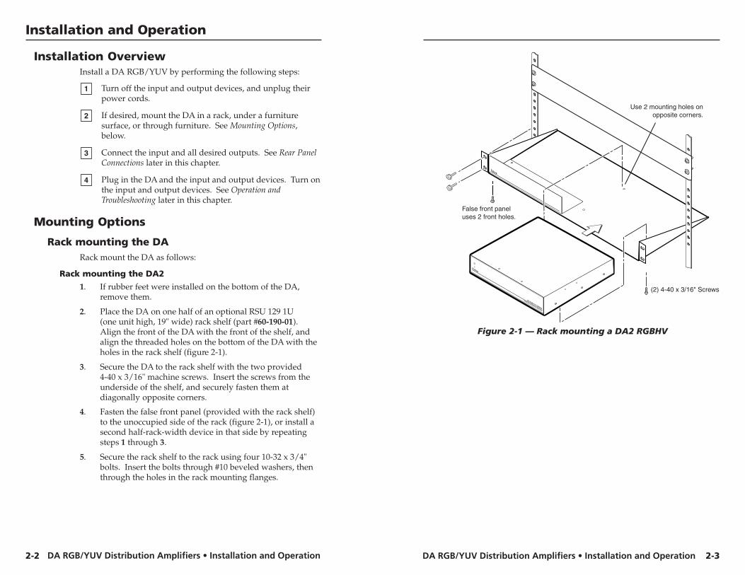
Figure 2-1 — Rack mounting a DA2 RGBHV
Installation OverviewInstall a DA RGB/YUV by performing the following steps:
1 Turn off the input and output devices, and unplug theirpower cords.
2 If desired, mount the DA in a rack, under a furnituresurface, or through furniture. See Mounting Options,below.
3 Connect the input and all desired outputs. See Rear PanelConnections later in this chapter.
4 Plug in the DA and the input and output devices. Turn onthe input and output devices. See Operation andTroubleshooting later in this chapter.
Mounting Options
Rack mounting the DARack mount the DA as follows:
Rack mounting the DA2
1. If rubber feet were installed on the bottom of the DA,remove them.
2. Place the DA on one half of an optional RSU 129 1U(one unit high, 19" wide) rack shelf (part #60-190-01).Align the front of the DA with the front of the shelf, andalign the threaded holes on the bottom of the DA with theholes in the rack shelf (figure 2-1).
3. Secure the DA to the rack shelf with the two provided4-40 x 3/16" machine screws. Insert the screws from theunderside of the shelf, and securely fasten them atdiagonally opposite corners.
4. Fasten the false front panel (provided with the rack shelf)to the unoccupied side of the rack (figure 2-1), or install asecond half-rack-width device in that side by repeatingsteps 1 through 3.
5. Secure the rack shelf to the rack using four 10-32 x 3/4"bolts. Insert the bolts through #10 beveled washers, thenthrough the holes in the rack mounting flanges.
2-2
DA RGB/YUV Distribution Amplifiers • Installation and OperationDA RGB/YUV Distribution Amplifiers • Installation and Operation
Installation and Operation, cont’d
2-52-4
Rack mounting the DA4 and DA6
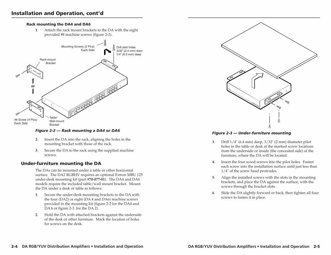
1. Attach the rack mount brackets to the DA with the eightprovided #8 machine screws (figure 2-2).
#8 Screw (4 Plcs)Each Side
Mounting Screws (2 Plcs)Each Side
Rack-mountBracket
Table/Wall-mountBracket
Drill pilot holes3/32” (2.4 mm) diam1/4” (6.3 mm) deep
or
INPUT
Y
DIGITAL
AUDIO
R-Y
B-Y
100-240V 1.3A
50-60Hz
DA6 YUV A
OUTPUT 1
OUTPUT 2
DIGITAL
AUDIO
DIGITAL
AUDIOY
R-Y
B-Y
Y
R-Y
B-Y
DIGITAL
AUDIO
DIGITAL
AUDIOY
R-Y
B-Y
Y
R-Y
B-Y
OUTPUT 3
OUTPUT 4
DIGITAL
AUDIO
DIGITAL
AUDIOY
R-Y
B-Y
Y
R-Y
B-Y
OUTPUT 5
OUTPUT 6
AC/DC
SPARE
ON
Figure 2-2 — Rack mounting a DA4 or DA6
2. Insert the DA into the rack, aligning the holes in themounting bracket with those of the rack.
3. Secure the DA to the rack using the supplied machinescrews.
Under-furniture mounting the DAThe DAs can be mounted under a table or other horizontalsurface. The DA2 RGBHV requires an optional Extron MBU 125under-desk mounting kit (part #70-077-01). The DA4 and DA6models require the included table/wall mount bracket. Mountthe DA under a desk or table as follows:
1. Secure the under-desk mounting brackets to the DA withthe four (DA2) or eight (DA 4 and DA6) machine screwsprovided in the mounting kit (figure 2-2 for the DA4 andDA 6 or figure 2-3 for the DA 2).
2. Hold the DA with attached brackets against the undersideof the desk or other furniture. Mark the location of holesfor screws on the desk.
DA RGB/YUV SERIES
WIDEBAND DISTRIBUTION AMPLIFIER
Figure 2-3 — Under-furniture mounting
3. Drill 1/4" (6.4 mm) deep, 3/32" (2 mm) diameter pilotholes in the table or desk at the marked screw locationsfrom the underside or inside (the concealed side) of thefurniture, where the DA will be located.
4. Insert the four wood screws into the pilot holes. Fasteneach screw into the installation surface until just less than1/4" of the screw head protrudes.
5. Align the installed screws with the slots in the mountingbrackets, and place the DA against the surface, with thescrews through the bracket slots.
6. Slide the DA slightly forward or back, then tighten all fourscrews to fasten it in place.
DA RGB/YUV Distribution Amplifiers • Installation and OperationDA RGB/YUV Distribution Amplifiers • Installation and Operation
Installation and Operation, cont’d
2-6
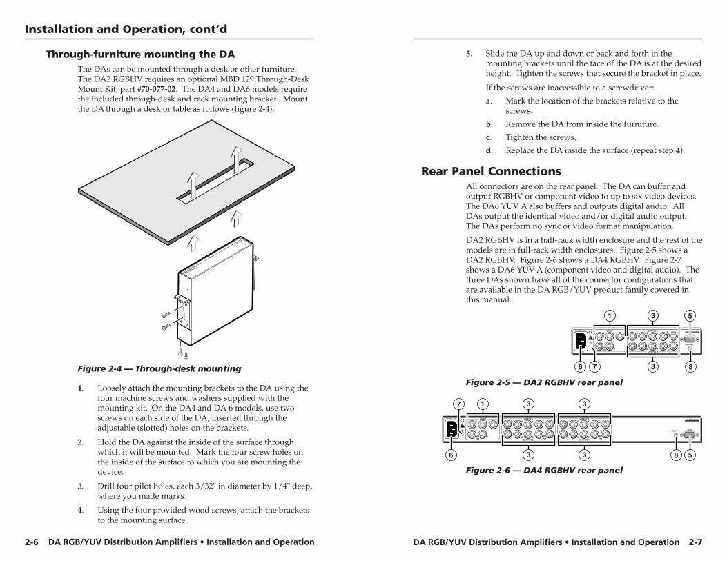
Through-furniture mounting the DAThe DAs can be mounted through a desk or other furniture.The DA2 RGBHV requires an optional MBD 129 Through-DeskMount Kit, part #70-077-02. The DA4 and DA6 models requirethe included through-desk and rack mounting bracket. Mountthe DA through a desk or table as follows (figure 2-4):
DA RGB/YUV SERIES
WIDEBAND DISTRIBUTION AMPLIFIER
Figure 2-4 — Through-desk mounting
1. Loosely attach the mounting brackets to the DA using thefour machine screws and washers supplied with themounting kit. On the DA4 and DA 6 models, use twoscrews on each side of the DA, inserted through theadjustable (slotted) holes on the brackets.
2. Hold the DA against the inside of the surface throughwhich it will be mounted. Mark the four screw holes onthe inside of the surface to which you are mounting thedevice.
3. Drill four pilot holes, each 3/32" in diameter by 1/4" deep,where you made marks.
4. Using the four provided wood screws, attach the bracketsto the mounting surface.
2-7
5. Slide the DA up and down or back and forth in themounting brackets until the face of the DA is at the desiredheight. Tighten the screws that secure the bracket in place.
If the screws are inaccessible to a screwdriver:
a. Mark the location of the brackets relative to thescrews.
b. Remove the DA from inside the furniture.
c. Tighten the screws.
d. Replace the DA inside the surface (repeat step 4).
Rear Panel ConnectionsAll connectors are on the rear panel. The DA can buffer andoutput RGBHV or component video to up to six video devices.The DA6 YUV A also buffers and outputs digital audio. AllDAs output the identical video and/or digital audio output.The DAs perform no sync or video format manipulation.
DA2 RGBHV is in a half-rack width enclosure and the rest of themodels are in full-rack width enclosures. Figure 2-5 shows aDA2 RGBHV. Figure 2-6 shows a DA4 RGBHV. Figure 2-7shows a DA6 YUV A (component video and digital audio). Thethree DAs shown have all of the connector configurations thatare available in the DA RGB/YUV product family covered inthis manual.
100-240V 0.2A
50-60Hz
INPUT OUTPUT 1
OUTPUT 2
R
HH/V
G
V
HH/V
V
HH/V V
B R G B
R G B
DA2 RGBHVMUTE
AC/DCGAIN/PEAK
ON
6 8
1 3
3
5
7
Figure 2-5 — DA2 RGBHV rear panel
100-240V 1.3A
50-60Hz
INPUT OUTPUT 1
OUTPUT 2
R
HH/V
G
V
HH/V
V
HH/V V
B R G B
R G B
DA4 RGBHV
MUTEAC/DCGAIN/PEAK
ON
OUTPUT 3
OUTPUT 4
HH/V
V
HH/V
V
R G B
R G B
8 56
1 3 3
3 3
7
Figure 2-6 — DA4 RGBHV rear panel
DA RGB/YUV Distribution Amplifiers • Installation and OperationDA RGB/YUV Distribution Amplifiers • Installation and Operation
Installation and Operation, cont’d
2-92-8
100-240V 1.3A
50-60Hz
INPUT OUTPUT 1
OUTPUT 2
Y
DIGITALAUDIO
DIGITALAUDIO
DIGITALAUDIO
R-Y B-Y Y R-Y B-Y
Y R-Y B-Y
DIGITALAUDIO
DIGITALAUDIO
Y R-Y B-Y
Y R-Y B-Y
DIGITALAUDIO
DIGITALAUDIO
Y R-Y B-Y
Y R-Y B-Y
DA6 YUV AOUTPUT 3
OUTPUT 4
OUTPUT 5
OUTPUT 6
AC/DCSPARE
ON
6 2 4 4
4 41 3 3
3 3 4
43
3
7
8
Figure 2-7 — DA6 YUV A rear panel
Input connections
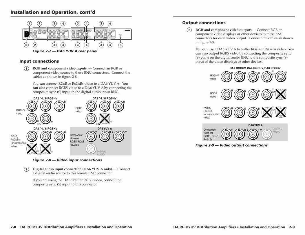
1 RGB and component video inputs — Connect an RGB orcomponent video source to these BNC connectors. Connect thecables as shown in figure 2-8.
You can connect RGsB or RsGsBs video to a DA6 YUV A. Youcan also connect RGBS video to a DA6 YUV A by connecting thecomposite sync (S) input to the digital audio input BNC.
RGBHVvideo
RGBSvideo
RGsB,RsGsBs(or componentvideo)
Componentvideo (orRGBS, RGsB,RsGsBs
DA6 YUV A
R
HH/V
G
V
B R
HH/V
G
V
B
R
HH/V
G
V
B Y
DA2 / 4 / 6 RGBHV DA2 / 4 / 6 RGBHV
DA2 / 4 / 6 RGBHVR-Y B-Y
DIGITALAUDIO
Figure 2-8 — Video input connections
2 Digital audio input connection (DA6 YUV A only) — Connecta digital audio source to this female BNC connector.
If you are using the DA to buffer RGBS video, connect thecomposite sync (S) input to this connector.
Output connections
3 RGB and component video outputs — Connect RGB orcomponent video displays or other devices to these BNCconnectors for each video output. Connect the cables as shownin figure 2-9.
You can use a DA6 YUV A to buffer RGsB or RsGsBs video. Youcan also output RGBS video by connecting the composite sync(S) plane on the digital audio BNC to the composite sync (S)input of the video displays or other devices.
RGBHVvideo
RGBSvideo
RGsB,RsGsBs(or componentvideo)
Componentvideo (orRGBS, RGsB,RsGsBs
DA6 YUV A
DA2 RGBHV, DA4 RGBHV, DA6 RGBHVHH/V
VR G B
HH/V
VR G B
HH/V
VR G B
DIGITALAUDIOY R-Y B-Y
Figure 2-9 — Video output connections
DA RGB/YUV Distribution Amplifiers • Installation and OperationDA RGB/YUV Distribution Amplifiers • Installation and Operation
Installation and Operation, cont’d
4 Digital audio output (DA6 YUV A only) — Connect digitalaudio devices to these female BNC connectors for each audiooutput.
If you are using the DA to buffer RGBS video, connect thisconnector to the composite sync (S) input of the video displaysor other devices.
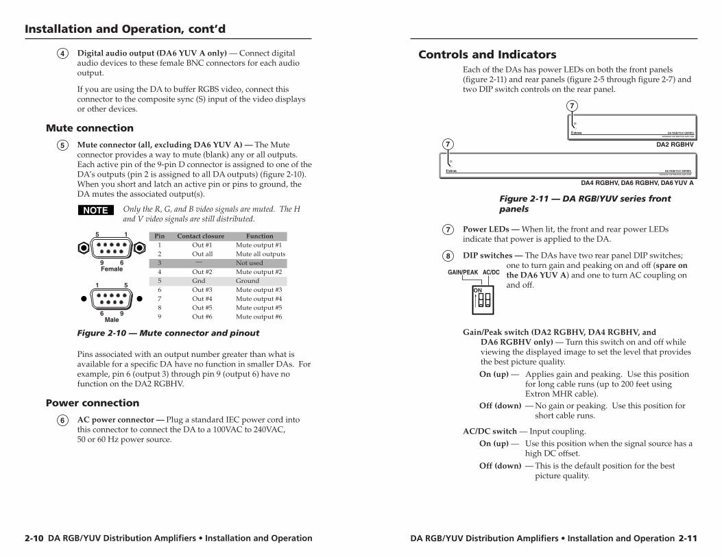
Mute connection
5 Mute connector (all, excluding DA6 YUV A) — The Muteconnector provides a way to mute (blank) any or all outputs.Each active pin of the 9-pin D connector is assigned to one of theDA’s outputs (pin 2 is assigned to all DA outputs) (figure 2-10).When you short and latch an active pin or pins to ground, theDA mutes the associated output(s).
Only the R, G, and B video signals are muted. The Hand V video signals are still distributed.
Pin Contact closure Function1 Out #1 Mute output #12
—Out all Mute all outputs
3 Not used4 Out #2 Mute output #25 Gnd Ground6 Out #3
Out #4Out #5Out #6
Mute output #3
Mute output #6
Mute output #4Mute output #5
789
Female
5 1
9 6
Male
1 5
6 9
Figure 2-10 — Mute connector and pinout
Pins associated with an output number greater than what isavailable for a specific DA have no function in smaller DAs. Forexample, pin 6 (output 3) through pin 9 (output 6) have nofunction on the DA2 RGBHV.
Power connection
6 AC power connector — Plug a standard IEC power cord intothis connector to connect the DA to a 100VAC to 240VAC,50 or 60 Hz power source.
2-10
AC/DCGAIN/PEAK
ON
Controls and IndicatorsEach of the DAs has power LEDs on both the front panels(figure 2-11) and rear panels (figure 2-5 through figure 2-7) andtwo DIP switch controls on the rear panel.
DA RGB/YUV SERIESWIDEBAND DISTRIBUTION AMPLIFIER
DA RGB/YUV SERIES
DA2 RGBHV
WIDEBAND DISTRIBUTION AMPLIFIER
DA4 RGBHV, DA6 RGBHV, DA6 YUV A
7
7
Figure 2-11 — DA RGB/YUV series frontpanels
7 Power LEDs — When lit, the front and rear power LEDsindicate that power is applied to the DA.
8 DIP switches — The DAs have two rear panel DIP switches;one to turn gain and peaking on and off (spare onthe DA6 YUV A) and one to turn AC coupling onand off.
Gain/Peak switch (DA2 RGBHV, DA4 RGBHV, andDA6 RGBHV only) — Turn this switch on and off whileviewing the displayed image to set the level that providesthe best picture quality.
On (up) — Applies gain and peaking. Use this positionfor long cable runs (up to 200 feet usingExtron MHR cable).
Off (down) — No gain or peaking. Use this position forshort cable runs.
AC/DC switch — Input coupling.On (up) — Use this position when the signal source has a
high DC offset.
Off (down) — This is the default position for the bestpicture quality.
2-11
DA RGB/YUV Distribution Amplifiers • Installation and Operation
Installation and Operation, cont’d
DA RGB/YUV Distribution Amplifiers
AAppendix A
Reference Information
Specifications
Part Numbers
Operation and TroubleshootingConnect the power cords and turn on the displays (projectors ormonitors), the DA, and the input device (computer). The imageshould appear on the screens.
If the image does not appear or is not displayed correctly
1. Ensure that all devices are plugged in.
2. Make sure that each device is receiving power. The DA’sfront and rear panel power LEDs indicate if the DA isreceiving power.
3. Check the cabling and make adjustments as needed.
4. If all displays are blank (DA2 RGBHV, DA4 RGBHV,and DA6 RGBHV only), check that a contact closuredevice is not set to mute all outputs via the DA’s Muteconnector (see Mute connection and item 5 , earlier in thischapter).
5. If individual displays are blank (DA2 RGBHV,DA4 RGBHV, and DA6 RGBHV only), check to ensurethat a contact closure device is not set to mute theindividual outputs via the DA’s Mute connector (see Muteconnection and item 5 , earlier in this chapter).
6. (DA2 RGBHV, DA4 RGBHV, and DA6 RGBHV only) Ifthe edges of the image seem to exceed their boundaries orif thin lines and sharp edges look thick and fuzzy, trychanging the Gain/Peak DIP switch to On (up) (seeControls and Indicators and item 8 , earlier in this chapter).If the image is too bright, turn the Gain/Peak switch to Off(down).
7. Call the Extron S3 Sales & Technical Support Hotline ifnecessary.
2-12
DA RGB/YUV Distribution Amplifiers • Reference InformationDA RGB/YUV Distribution Amplifiers • Reference Information
Reference Information
A-3A-2
Specifications
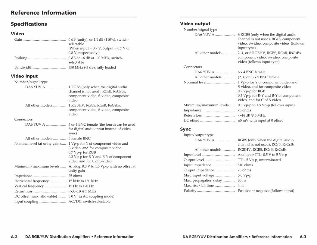
VideoGain ............................................... 0 dB (unity), or 1.1 dB (110%), switch-
selectable(When input = 0.7 V, output = 0.7 V or0.8 V, respectively.)
Peaking .......................................... 0 dB or +6 dB at 100 MHz, switch-selectable
Bandwidth .................................... 350 MHz (-3 dB), fully loaded
Video inputNumber/signal type
DA6 YUV A ...................... 1 RGBS (only when the digital audiochannel is not used), RGsB, RsGsBs,component video, S-video, compositevideo
All other models .............. 1 RGBHV, RGBS, RGsB, RsGsBs,component video, S-video, compositevideo
ConnectorsDA6 YUV A ...................... 3 or 4 BNC female (the fourth can be used
for digital audio input instead of videosync)
All other models .............. 5 female BNCNominal level (at unity gain) ..... 1 Vp-p for Y of component video and
S-video, and for composite video0.7 Vp-p for RGB0.3 Vp-p for R-Y and B-Y of componentvideo, and for C of S-video
Minimum/maximum levels ...... Analog: 0.3 V to 1.5 Vp-p with no offset atunity gain
Impedance .................................... 75 ohmsHorizontal frequency .................. 15 kHz to 180 kHzVertical frequency ....................... 15 Hz to 170 HzReturn loss .................................... <-38 dB @ 5 MHzDC offset (max. allowable) ......... 5.0 V (in AC coupling mode)Input coupling.............................. AC/DC, switch-selectable
Video outputNumber/signal type
DA6 YUV A ...................... 6 RGBS (only when the digital audiochannel is not used), RGsB, componentvideo, S-video, composite video (followsinput type)
All other models .............. 2, 4, or 6 RGBHV, RGBS, RGsB, RsGsBs,component video, S-video, compositevideo (follows input type)
ConnectorsDA6 YUV A ...................... 6 x 4 BNC femaleAll other models .............. (2, 4, or 6) x 5 BNC female
Nominal level ............................... 1 Vp-p for Y of component video andS-video, and for composite video0.7 Vp-p for RGB0.3 Vp-p for R-Y and B-Y of componentvideo, and for C of S-video
Minimum/maximum levels ...... 0.3 Vp-p to 1.5 Vp-p (follows input)Impedance .................................... 75 ohmsReturn loss .................................... <-44 dB @ 5 MHzDC offset ....................................... ±5 mV with input at 0 offset
SyncInput/output type
DA6 YUV A ...................... RGBS (only when the digital audiochannel is not used), RGsB, RsGsBs
All other models .............. RGBHV, RGBS, RGsB, RsGsBsInput level ..................................... Analog or TTL: 0.5 V to 5 Vp-pOutput level .................................. TTL: 5 Vp-p, unterminatedInput impedance .......................... 510 ohmsOutput impedance ...................... 75 ohmsMax. input voltage ...................... 5.0 Vp-pMax. propagation delay .............. 35 nsMax. rise/fall time ....................... 4 nsPolarity .......................................... Positive or negative (follows input)
DA RGB/YUV Distribution Amplifiers • Reference InformationDA RGB/YUV Distribution Amplifiers • Reference Information
Reference Information
Digital audio — DA6 YUV A only
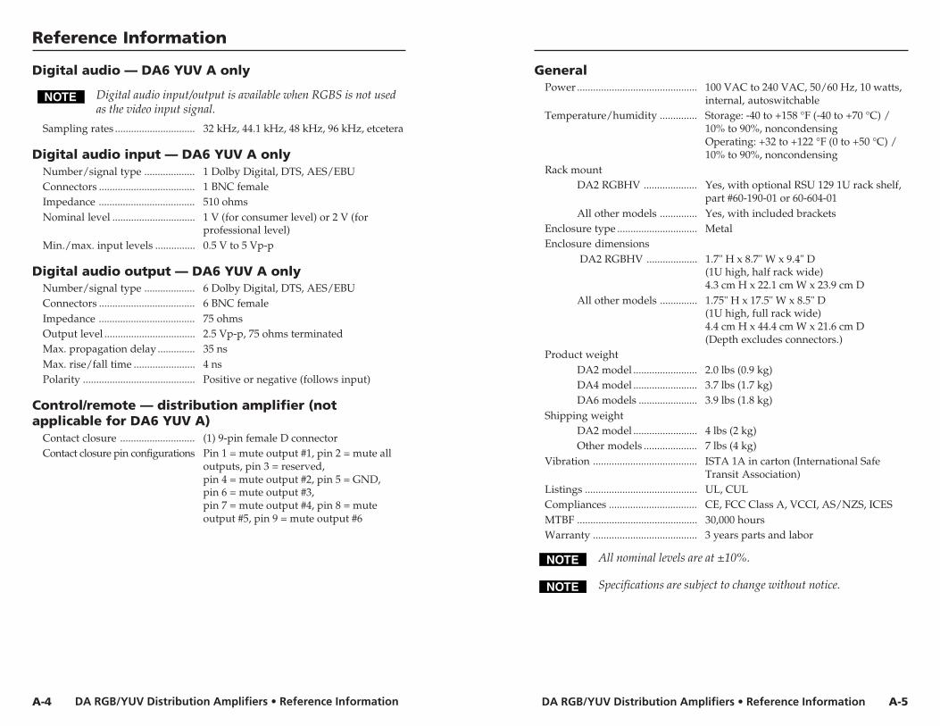
Digital audio input/output is available when RGBS is not usedas the video input signal.
Sampling rates .............................. 32 kHz, 44.1 kHz, 48 kHz, 96 kHz, etcetera
Digital audio input — DA6 YUV A onlyNumber/signal type ................... 1 Dolby Digital, DTS, AES/EBUConnectors .................................... 1 BNC femaleImpedance .................................... 510 ohmsNominal level ............................... 1 V (for consumer level) or 2 V (for
professional level)Min./max. input levels ............... 0.5 V to 5 Vp-p
Digital audio output — DA6 YUV A onlyNumber/signal type ................... 6 Dolby Digital, DTS, AES/EBUConnectors .................................... 6 BNC femaleImpedance .................................... 75 ohmsOutput level .................................. 2.5 Vp-p, 75 ohms terminatedMax. propagation delay .............. 35 nsMax. rise/fall time ....................... 4 nsPolarity .......................................... Positive or negative (follows input)
Control/remote — distribution amplifier (notapplicable for DA6 YUV A)
Contact closure ............................ (1) 9-pin female D connectorContact closure pin configurations Pin 1 = mute output #1, pin 2 = mute all
outputs, pin 3 = reserved,pin 4 = mute output #2, pin 5 = GND,pin 6 = mute output #3,pin 7 = mute output #4, pin 8 = muteoutput #5, pin 9 = mute output #6
A-5A-4
GeneralPower ............................................. 100 VAC to 240 VAC, 50/60 Hz, 10 watts,
internal, autoswitchableTemperature/humidity .............. Storage: -40 to +158 °F (-40 to +70 °C) /
10% to 90%, noncondensingOperating: +32 to +122 °F (0 to +50 °C) /10% to 90%, noncondensing
Rack mountDA2 RGBHV .................... Yes, with optional RSU 129 1U rack shelf,
part #60-190-01 or 60-604-01All other models .............. Yes, with included brackets
Enclosure type .............................. MetalEnclosure dimensions
DA2 RGBHV ................... 1.7" H x 8.7" W x 9.4" D(1U high, half rack wide)4.3 cm H x 22.1 cm W x 23.9 cm D
All other models .............. 1.75" H x 17.5" W x 8.5" D(1U high, full rack wide)4.4 cm H x 44.4 cm W x 21.6 cm D(Depth excludes connectors.)
Product weightDA2 model ........................ 2.0 lbs (0.9 kg)DA4 model ........................ 3.7 lbs (1.7 kg)DA6 models ...................... 3.9 lbs (1.8 kg)
Shipping weightDA2 model ........................ 4 lbs (2 kg)Other models .................... 7 lbs (4 kg)
Vibration ....................................... ISTA 1A in carton (International SafeTransit Association)
Listings .......................................... UL, CULCompliances ................................. CE, FCC Class A, VCCI, AS/NZS, ICESMTBF ............................................. 30,000 hoursWarranty ....................................... 3 years parts and labor
All nominal levels are at ±10%.
Specifications are subject to change without notice.
DA RGB/YUV Distribution Amplifiers • Reference InformationDA RGB/YUV Distribution Amplifiers • Reference Information
Reference Information, cont’d
A-6
Part Numbers
DA part numbers
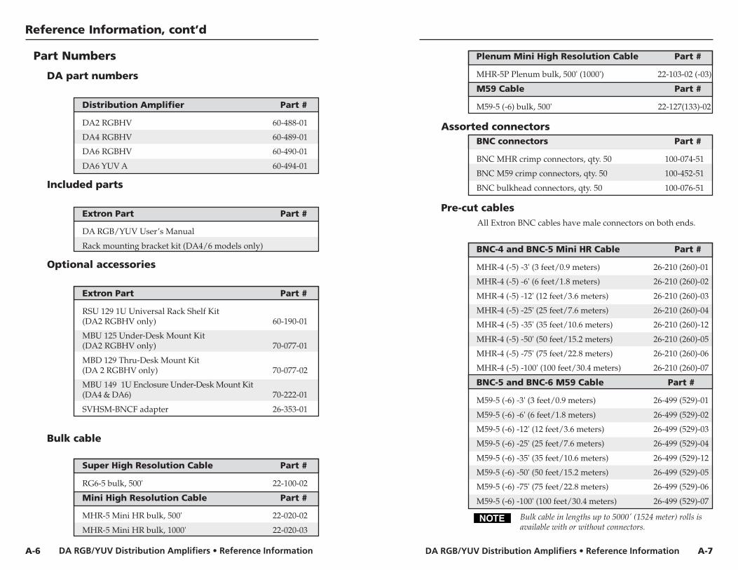
Distribution Amplifier Part #
DA2 RGBHV 60-488-01
DA4 RGBHV 60-489-01
DA6 RGBHV 60-490-01
DA6 YUV A 60-494-01
Included parts
Extron Part Part #
DA RGB/YUV User’s Manual
Rack mounting bracket kit (DA4/6 models only)
Optional accessories
Extron Part Part #
RSU 129 1U Universal Rack Shelf Kit(DA2 RGBHV only) 60-190-01
MBU 125 Under-Desk Mount Kit(DA2 RGBHV only) 70-077-01
MBD 129 Thru-Desk Mount Kit(DA 2 RGBHV only) 70-077-02
MBU 149 1U Enclosure Under-Desk Mount Kit(DA4 & DA6) 70-222-01
SVHSM-BNCF adapter 26-353-01
Bulk cable
Super High Resolution Cable Part #
RG6-5 bulk, 500' 22-100-02
Mini High Resolution Cable Part #
MHR-5 Mini HR bulk, 500' 22-020-02
MHR-5 Mini HR bulk, 1000' 22-020-03
Plenum Mini High Resolution Cable Part #
MHR-5P Plenum bulk, 500' (1000') 22-103-02 (-03)
M59 Cable Part #
M59-5 (-6) bulk, 500' 22-127(133)-02
Assorted connectorsBNC connectors Part #
BNC MHR crimp connectors, qty. 50 100-074-51
BNC M59 crimp connectors, qty. 50 100-452-51
BNC bulkhead connectors, qty. 50 100-076-51
Pre-cut cables All Extron BNC cables have male connectors on both ends.
BNC-4 and BNC-5 Mini HR Cable Part #
MHR-4 (-5) -3' (3 feet/0.9 meters) 26-210 (260)-01
MHR-4 (-5) -6' (6 feet/1.8 meters) 26-210 (260)-02
MHR-4 (-5) -12' (12 feet/3.6 meters) 26-210 (260)-03
MHR-4 (-5) -25' (25 feet/7.6 meters) 26-210 (260)-04
MHR-4 (-5) -35' (35 feet/10.6 meters) 26-210 (260)-12
MHR-4 (-5) -50' (50 feet/15.2 meters) 26-210 (260)-05
MHR-4 (-5) -75' (75 feet/22.8 meters) 26-210 (260)-06
MHR-4 (-5) -100' (100 feet/30.4 meters) 26-210 (260)-07
BNC-5 and BNC-6 M59 Cable Part #
M59-5 (-6) -3' (3 feet/0.9 meters) 26-499 (529)-01
M59-5 (-6) -6' (6 feet/1.8 meters) 26-499 (529)-02
M59-5 (-6) -12' (12 feet/3.6 meters) 26-499 (529)-03
M59-5 (-6) -25' (25 feet/7.6 meters) 26-499 (529)-04
M59-5 (-6) -35' (35 feet/10.6 meters) 26-499 (529)-12
M59-5 (-6) -50' (50 feet/15.2 meters) 26-499 (529)-05
M59-5 (-6) -75' (75 feet/22.8 meters) 26-499 (529)-06
M59-5 (-6) -100' (100 feet/30.4 meters) 26-499 (529)-07
Bulk cable in lengths up to 5000' (1524 meter) rolls isavailable with or without connectors.
A-7
DA RGB/YUV Distribution Amplifiers • Reference Information
Reference Information, cont’d
A-8