Embed Size (px)
Citation preview
DA-662A Series Software User’s Manual
First Edition, August 2015
www.moxa.com/product
© 2015 Moxa Inc. All rights reserved.
DA-662A Series Software User’s Manual
The software described in this manual is furnished under a license agreement and may be used only in accordance with
the terms of that agreement.
Copyright Notice
© 2015 Moxa Inc. All rights reserved.
Trademarks
The MOXA logo is a registered trademark of Moxa Inc.
All other trademarks or registered marks in this manual belong to their respective manufacturers.
Disclaimer
Information in this document is subject to change without notice and does not represent a commitment on the part of
Moxa.
Moxa provides this document as is, without warranty of any kind, either expressed or implied, including, but not limited
to, its particular purpose. Moxa reserves the right to make improvements and/or changes to this manual, or to the
products and/or the programs described in this manual, at any time.
Information provided in this manual is intended to be accurate and reliable. However, Moxa assumes no responsibility for
its use, or for any infringements on the rights of third parties that may result from its use.
This product might include unintentional technical or typographical errors. Changes are periodically made to the
information herein to correct such errors, and these changes are incorporated into new editions of the publication.
Technical Support Contact Information
www.moxa.com/support
Moxa Americas
Toll-free: 1-888-669-2872
Tel: +1-714-528-6777
Fax: +1-714-528-6778
Moxa China (Shanghai office)
Toll-free: 800-820-5036
Tel: +86-21-5258-9955
Fax: +86-21-5258-5505
Moxa Europe
Tel: +49-89-3 70 03 99-0
Fax: +49-89-3 70 03 99-99
Moxa Asia-Pacific
Tel: +886-2-8919-1230
Fax: +886-2-8919-1231
Moxa India
Tel: +91-80-4172-9088
Fax: +91-80-4132-1045
Table of Contents
1. Introduction ...................................................................................................................................... 1-1 Overview ........................................................................................................................................... 1-2 Software Architecture .......................................................................................................................... 1-2
Journaling Flash File System (JFFS2) ............................................................................................. 1-3 Software Package ........................................................................................................................ 1-4
2. Getting Started ................................................................................................................................. 2-1 Powering on the DA-662A Series .......................................................................................................... 2-2 Connecting the DA-662A series to a PC ................................................................................................. 2-2
Serial Console ............................................................................................................................. 2-2 Telnet Console ............................................................................................................................ 2-3 SSH Console ............................................................................................................................... 2-4
Configuring the Ethernet Interface ........................................................................................................ 2-4 Modifying Network Settings with the Serial Console ......................................................................... 2-5 Modifying Network Settings over the Network ................................................................................. 2-6
Test Program—Developing Hello.c ......................................................................................................... 2-6 Installing the Tool Chain (Linux) .................................................................................................... 2-7 Checking the Flash Memory Space ................................................................................................. 2-7 Compiling Hello.c ........................................................................................................................ 2-7 Uploading and Running the ―Hello‖ Program ................................................................................... 2-8
Developing Your First Application .......................................................................................................... 2-8 Testing Environment .................................................................................................................... 2-9 Compiling tcps2.c ........................................................................................................................ 2-9 Uploading and Running the ―tcps2-release‖ Program ...................................................................... 2-10 Testing Procedure Summary ....................................................................................................... 2-12
3. Managing Embedded Linux ................................................................................................................ 3-1 System Version Information ................................................................................................................. 3-2
Upgrading the Firmware ............................................................................................................... 3-2 Loading Factory Defaults .............................................................................................................. 3-4
Enabling and Disabling Daemons .......................................................................................................... 3-4 Setting the Run-level .......................................................................................................................... 3-7 Adjusting the System Time .................................................................................................................. 3-8
Setting the Time Manually ............................................................................................................ 3-8 NTP Client .................................................................................................................................. 3-9 Updating the Time Automatically ................................................................................................... 3-9
Cron—Daemon for Executing Scheduled Commands .............................................................................. 3-10 Connecting Peripherals ...................................................................................................................... 3-11
USB Mass Storage ..................................................................................................................... 3-11 CF Mass Storage ....................................................................................................................... 3-11
4. Managing Communications ............................................................................................................... 4-1 Telnet / FTP ....................................................................................................................................... 4-2 DNS .................................................................................................................................................. 4-2 Web Service—Apache .......................................................................................................................... 4-3 IPTABLES .......................................................................................................................................... 4-4 NAT .................................................................................................................................................. 4-7
NAT Example .............................................................................................................................. 4-8 Enabling NAT at Bootup ............................................................................................................... 4-8
Dial-up Service—PPP ........................................................................................................................... 4-9 PPPoE.............................................................................................................................................. 4-12 NFS (Network File System) ................................................................................................................ 4-13
Setting up the DA-662A series as an NFS Client ............................................................................ 4-14 SNMP .............................................................................................................................................. 4-14
5. Programmer's Guide ......................................................................................................................... 5-1 Notes on Migrating Your Application from the DA-660/662 to the DA-662A series ....................................... 5-2
Big endian to Little endian ............................................................................................................ 5-2 The difference between Big endian and Little endian ........................................................................ 5-3 Be careful when developing/migrating programs ............................................................................. 5-3 Useful APIs for converting Big endian and Little endian .................................................................... 5-3 Conversion Example .................................................................................................................... 5-3 Steps for Migrating to the DA-662A ............................................................................................... 5-4
Linux Tool Chain Introduction ............................................................................................................... 5-4 Device API ......................................................................................................................................... 5-5 RTC (Real-time Clock) ......................................................................................................................... 5-6 Buzzer ............................................................................................................................................... 5-6 WDT (Watchdog Timer) ....................................................................................................................... 5-6 UART .............................................................................................................................................. 5-10 LCM ................................................................................................................................................ 5-11 KeyPad ............................................................................................................................................ 5-12

Make File Example ............................................................................................................................ 5-12
A. System Commands ............................................................................................................................ A-1 Linux normal command utility collection ................................................................................................ A-1
File Manager ............................................................................................................................... A-1 Editor ........................................................................................................................................ A-1 Network ..................................................................................................................................... A-2 Process ...................................................................................................................................... A-2 Other ......................................................................................................................................... A-2 Moxa Special Utilities ................................................................................................................... A-2
B. Using the Push Buttons to Operate the LCD Screen ........................................................................... B-1
1 1. Introduction
The DA-662A computers are RISC-based, ready-to-run embedded computers designed for industrial data
acquisition applications. Each model has 16 RS-232/422/485 serial ports, 1 CF socket, and 2 USB hosts based
on the Moxa MACRO 500 MHz communication processor. The DA-662A has 4 Ethernet ports. The casing is a
standard 1U, 19-inch wide rack-mounted rugged enclosure. The robust, rack-mountable mechanism design
provides the hardened protection needed for industrial environment applications, and makes it easy for users
to install the DA-662A series on a standard 19-inch rack. The DA-662A computers are ideal for applications that
require a distributed embedded technology, such as SCADA systems, plant floor automation, and power
electricity monitoring applications.
The following topics are covered in this chapter:
Overview
Software Architecture
Journaling Flash File System (JFFS2)
Software Package
DA-662A Series Software Introduction
1-2
Overview The DA-662A series embedded computers are ideal for embedded applications. The computers feature a RISC
CPU, RAM memory, and communication ports for connecting to RS-232/422/485 serial devices. The DA-662A
has 4 Ethernet ports.
The DA-662A series computers use a Moxa MACRO 500 Mhz RISC CPU. Unlike the X86 CPU, which uses a CISC
design, the RISC architecture and modern semiconductor technology provide the DA-662A series with a
powerful computing engine and communication functions, but without generating a lot of heat. The built-in 32
MB NOR Flash ROM and 128 MB SDRAM give you enough memory to install your application software directly
on the computer. In addition, multiple LAN ports are built into the RISC CPU. The combination of advanced
networking capability and control over serial devices makes the DA-662A series an ideal communication
platform for data acquisition and industrial control applications.
The DA-662A series‘ pre-installed Linux operating system (OS) provides an open software operating system for
your software program development. Software written for desktop PCs is easily ported to the computer with a
GNU cross compiler, without the need to modify the source code. The operating system, device drivers (e.g.,
Keypad, LCM, and Buzzer control) and your own applications can all be stored in the NOR Flash memory.
The DA-662A Linux series has five models. Choose 8 or 16 serial ports, additional isolated serial port protection,
or dual power inputs, all with the same hardware and software features suitable for different industrial
applications.
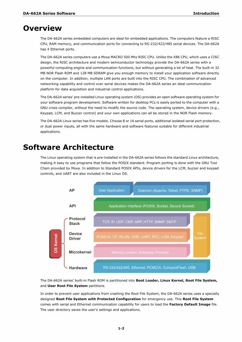
Software Architecture The Linux operating system that is pre-installed in the DA-662A series follows the standard Linux architecture,
making it easy to use programs that follow the POSIX standard. Program porting is done with the GNU Tool
Chain provided by Moxa. In addition to Standard POSIX APIs, device drivers for the LCM, buzzer and keypad
controls, and UART are also included in the Linux OS.
The DA-662A series‘ built-in Flash ROM is partitioned into Boot Loader, Linux Kernel, Root File System,
and User Root File System partitions.
In order to prevent user applications from crashing the Root File System, the DA-662A series uses a specially
designed Root File System with Protected Configuration for emergency use. This Root File System
comes with serial and Ethernet communication capability for users to load the Factory Default Image file.
The user directory saves the user‘s settings and applications.
DA-662A Series Software Introduction
1-3
To improve system reliability, the DA-662A series has a built-in mechanism that prevents the system from
crashing. When the Linux kernel boots up, the kernel will mount the root file system for read only, and then
enable services and daemons. During this time, the kernel will start searching for system configuration
parameters via rc or inittab.
Normally, the kernel uses the Root File System to boot up the system. Since the Root File System is protected,
and cannot be changed by the user, this provides a ―safe‖ zone.
For more information about the memory map and programming, refer to Chapter 5, Programmer’s Guide.
Journaling Flash File System (JFFS2)
The User Root File System in the flash memory is formatted with the Journaling Flash File System (JFFS2).
The formatting process places a compressed file system in the flash memory, transparent to the user.
The Journaling Flash File System (JFFS2), which was developed by Axis Communications in Sweden, puts a file
system directly on the flash, instead of emulating a block device. It is designed for use on flash-ROM chips and
recognizes the special write requirements of a flash-ROM chip. JFFS2 implements wear-leveling to extend the
life of the flash disk, and stores the flash directory structure in the RAM. A log-structured file system is
maintained at all times. The system is always consistent, even if it encounters crashes or improper
power-downs, and does not require fsck (file system check) on boot-up.
JFFS2 is the newest version of JFFS. It provides improved wear-leveling and garbage-collection performance,
improved RAM footprint and response to system-memory pressure, improved concurrency and support for
suspending flash erases; marking of bad sectors with continued use of the remaining good sectors (which
enhances the write-life of the devices), native data compression inside the file system design, and support for
hard links.
The key features of JFFS2 are:
• Targets the Flash ROM directly
• Robustness
• Consistency across power failures
• No integrity scan (fsck) is required at boot time after normal or abnormal shutdown
• Explicit wear leveling
• Transparent compression
Although JFFS2 is a journaling file system, this does not preclude the loss of data. The file system will remain
in a consistent state across power failures and will always be mountable. However, if the board is powered
down during a write then the incomplete write will be rolled back on the next boot, but writes that have already
been completed will not be affected.
Additional information about JFFS2 is available at:
http://sources.redhat.com/jffs2/jffs2.pdf
http://developer.axis.com/software/jffs/
http://www.linux-mtd.infradead.org/
DA-662A Series Software Introduction
1-4
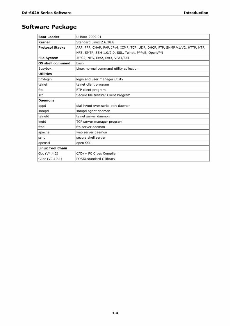
Software Package
Boot Loader U-Boot-2009.01
Kernel Standard Linux 2.6.38.8
Protocol Stacks ARP, PPP, CHAP, PAP, IPv4, ICMP, TCP, UDP, DHCP, FTP, SNMP V1/V2, HTTP, NTP,
NFS, SMTP, SSH 1.0/2.0, SSL, Telnet, PPPoE, OpenVPN
File System JFFS2, NFS, Ext2, Ext3, VFAT/FAT
OS shell command bash
Busybox Linux normal command utility collection
Utilities
tinylogin login and user manager utility
telnet telnet client program
ftp FTP client program
scp Secure file transfer Client Program
Daemons
pppd dial in/out over serial port daemon
snmpd snmpd agent daemon
telnetd telnet server daemon
inetd TCP server manager program
ftpd ftp server daemon
apache web server daemon
sshd secure shell server
openssl open SSL
Linux Tool Chain
Gcc (V4.4.2) C/C++ PC Cross Compiler
Glibc (V2.10.1) POSIX standard C library
2 2. Getting Started
In this chapter, we explain how to connect the DA-662A series, turn on the power, and then get started using
the programming and other functions.
The following topics are covered in this chapter:
Powering on the DA-662A Series
Connecting the DA-662A series to a PC
Serial Console
Telnet Console
SSH Console
Configuring the Ethernet Interface
Modifying Network Settings with the Serial Console
Modifying Network Settings over the Network
Test Program—Developing Hello.c
Installing the Tool Chain (Linux)
Checking the Flash Memory Space
Compiling Hello.c
Uploading and Running the ―Hello‖ Program
Developing Your First Application
Testing Environment
Compiling tcps2.c
Uploading and Running the ―tcps2-release‖ Program
Testing Procedure Summary
DA-662A Series Software Getting Started
2-2
Powering on the DA-662A Series Connect the SG wire to the Shielded Contact located in the upper left corner of the DA-662A series, and then
power on the computer by connecting it to the power adaptor. It takes about 30 to 60 seconds for the system
to boot up. Once the system is ready, the Ready LED will light up, and the model name of the computer will
appear on the LCM display.
NOTE After connecting the DA-662A series to the power supply, it will take about 30 to 60 seconds for the operating
system to boot up. The green Ready LED will not turn on until the operating system is ready.
Connecting the DA-662A series to a PC There are two ways to connect the DA-662A series to a PC: (1) Through the serial console port, and (2) via
Telnet over the network.
Serial Console
The serial console port gives users a convenient way of connecting to the DA-662A series‘ console utility. This
method is particularly useful when using the computer for the first time. The signal is transmitted over a direct
serial connection, so that you do not need to know any of the IP addresses in order to connect to the serial
console utility.
Use the serial console port settings shown below.
Baudrate 115200 bps
Parity None
Data bits 8
Stop bits: 1
Flow Control None
Terminal VT100
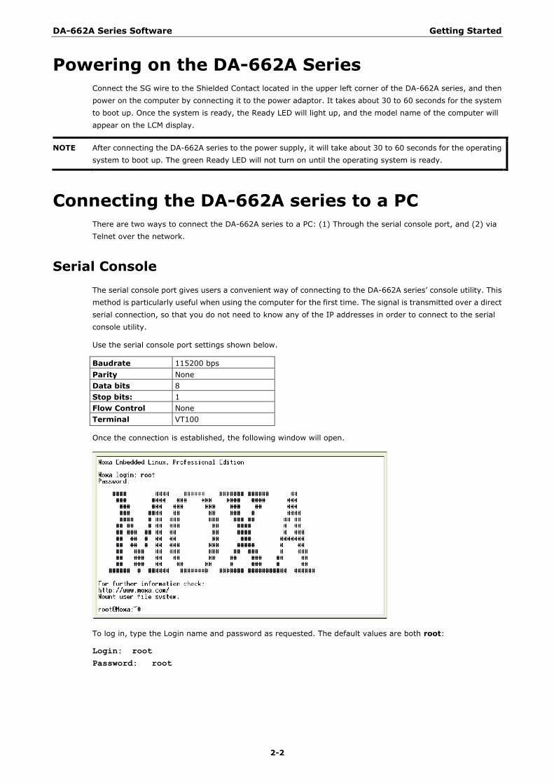
Once the connection is established, the following window will open.
To log in, type the Login name and password as requested. The default values are both root:
Login: root
Password: root
DA-662A Series Software Getting Started
2-3
Telnet Console
If you know at least one of the two IP addresses and netmasks, then you can use Telnet to connect to the
DA-662A series‘ console utility. The default IP address and Netmask for each of the these ports are given
below:
Default IP Address Netmask
LAN 1 192.168.3.127 255.255.255.0
LAN 2 192.168.4.127 255.255.255.0
LAN 3 192.168.5.127 255.255.255.0
LAN 4 192.168.6.127 255.255.255.0
Use a cross-over Ethernet cable to connect directly from your PC to the DA-662A series. You should first modify
your PC‘s IP address and netmask so that your PC is on the same subnet as one of the DA-662A series‘ LAN
ports. For example, if you connect to LAN 1, you can set your PC‘s IP address to 192.168.3.126 and netmask
to 255.255.255.0. If you connect to the LAN 2, you can set your PC‘s IP address to 192.168.4.126 and netmask
to 255.255.255.0.
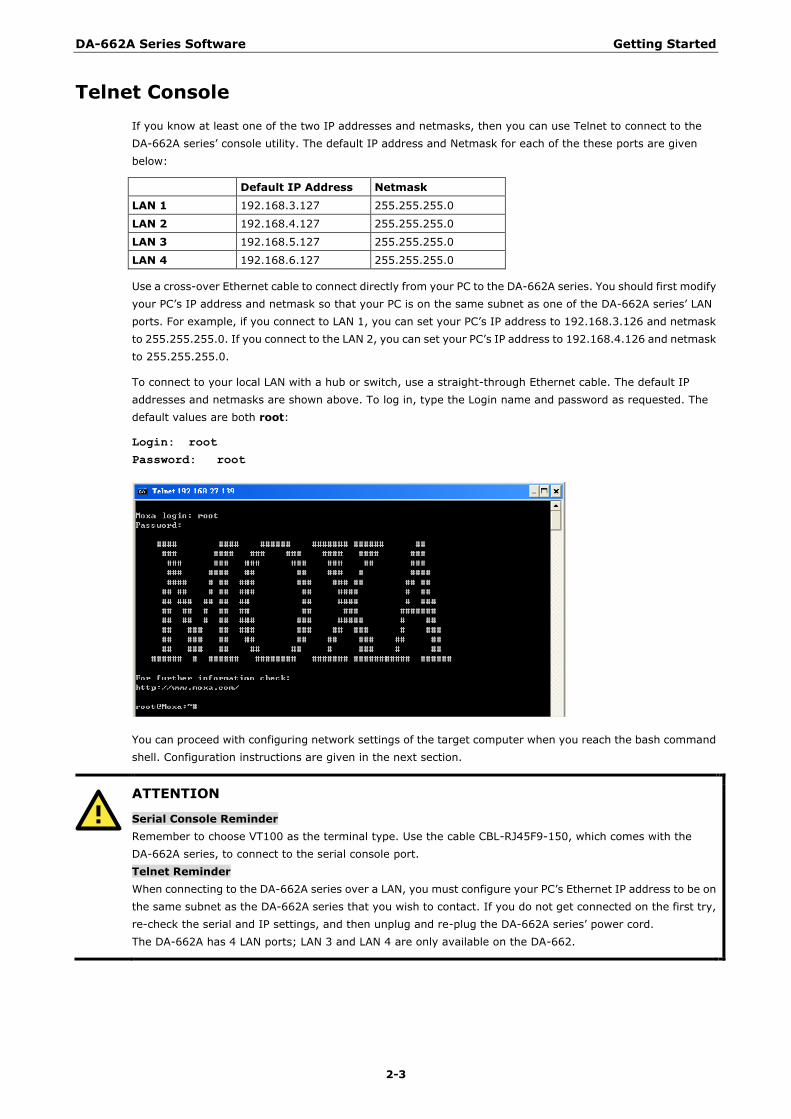
To connect to your local LAN with a hub or switch, use a straight-through Ethernet cable. The default IP
addresses and netmasks are shown above. To log in, type the Login name and password as requested. The
default values are both root:
Login: root
Password: root
You can proceed with configuring network settings of the target computer when you reach the bash command
shell. Configuration instructions are given in the next section.
ATTENTION
Serial Console Reminder
Remember to choose VT100 as the terminal type. Use the cable CBL-RJ45F9-150, which comes with the
DA-662A series, to connect to the serial console port.
Telnet Reminder
When connecting to the DA-662A series over a LAN, you must configure your PC‘s Ethernet IP address to be on
the same subnet as the DA-662A series that you wish to contact. If you do not get connected on the first try,
re-check the serial and IP settings, and then unplug and re-plug the DA-662A series‘ power cord.
The DA-662A has 4 LAN ports; LAN 3 and LAN 4 are only available on the DA-662.
DA-662A Series Software Getting Started
2-4
SSH Console
The DA-662A series supports an SSH Console to provide users with better security options.
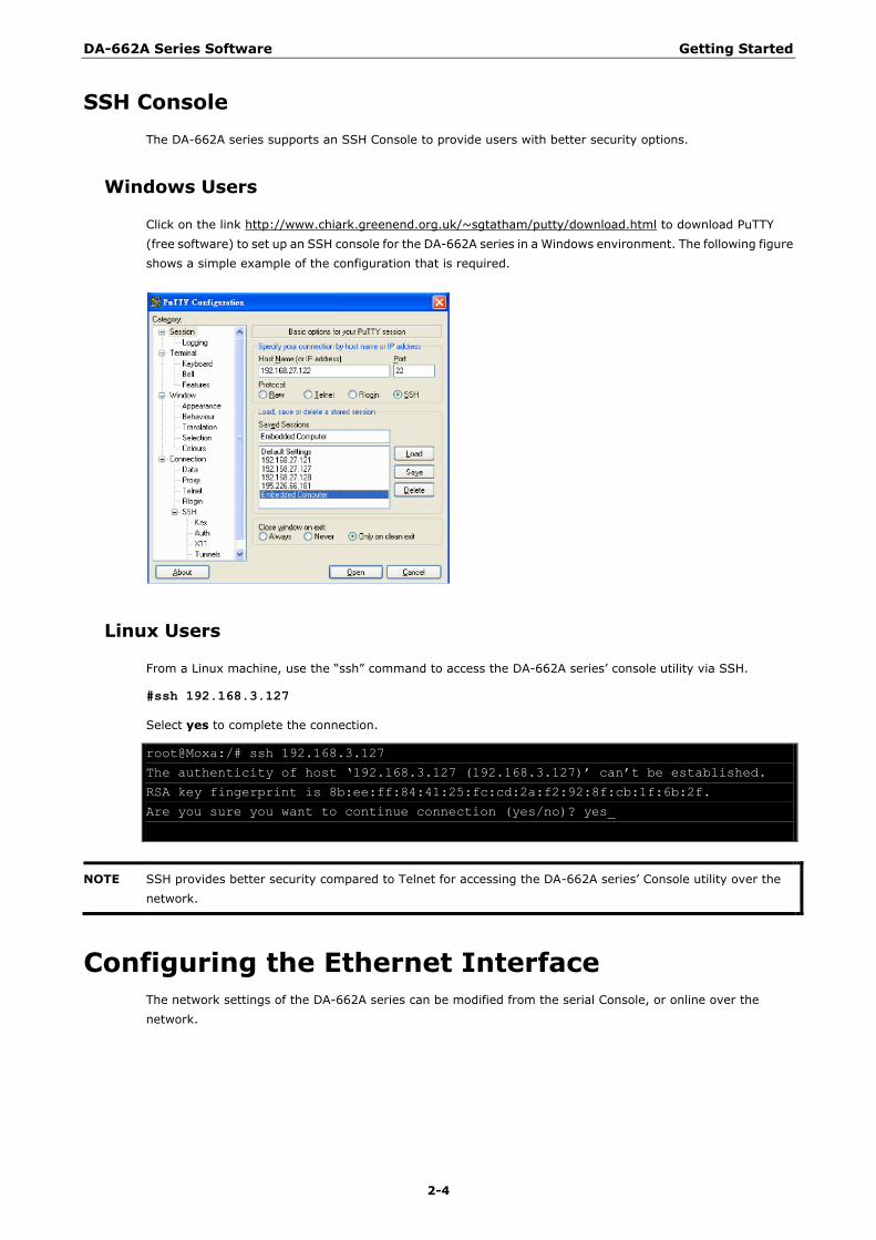
Windows Users
Click on the link http://www.chiark.greenend.org.uk/~sgtatham/putty/download.html to download PuTTY
(free software) to set up an SSH console for the DA-662A series in a Windows environment. The following figure
shows a simple example of the configuration that is required.
Linux Users
From a Linux machine, use the ―ssh‖ command to access the DA-662A series‘ console utility via SSH.
#ssh 192.168.3.127
Select yes to complete the connection.
root@Moxa:/# ssh 192.168.3.127
The authenticity of host ‗192.168.3.127 (192.168.3.127)‘ can‘t be established.
RSA key fingerprint is 8b:ee:ff:84:41:25:fc:cd:2a:f2:92:8f:cb:1f:6b:2f.
Are you sure you want to continue connection (yes/no)? yes_
NOTE SSH provides better security compared to Telnet for accessing the DA-662A series‘ Console utility over the
network.
Configuring the Ethernet Interface The network settings of the DA-662A series can be modified from the serial Console, or online over the
network.
DA-662A Series Software Getting Started
2-5
Modifying Network Settings with the Serial Console
In this section, we use the serial console to configure the network settings of the target computer.
1. Follow the instructions given in a previous section to access the Console Utility of the target computer via
the serial Console port, and then type #cd /etc/network to change directories.
root@Moxa:# cd /etc/network/
root@Moxa:/etc/network/#
2. Type #vi interfaces to edit the network configuration file with vi editor. You can configure the Ethernet
ports of the DA-662A series for static or dynamic (DHCP) IP addresses.
Static IP addresses:
As shown below, 4 network addresses need to be modified: address, network, netmask, and broadcast.
The default IP addresses are 192.168.3.127 for LAN1 and 192.168.4.127 for LAN2, with default netmask of
255.255.255.0.
# We always want the loopback interface.
auto eth0 eth1 eth2 eth3 eth4 lo
iface lo inet loopback
# embedded ethernet LAN1
iface eth0 inet static
address 192.168.3.127
network 192.168.3.0
netmask 255.255.255.0
broadcast 192.168.3.255
# embedded ethernet LAN2
iface eth1 inet static
address 192.168.4.127
network 192.168.4.0
netmask 255.255.255.0
broadcast 192.168.4.255
# embedded ethernet LAN3
iface eth2 inet static
address 192.168.5.127
network 192.168.5.0
Dynamic IP addresses:
By default, the DA-662A series is configured for ―static‖ IP addresses. To configure one or both LAN ports
to request an IP address dynamically, replace static with dhcp and then delete the address, network,
netmask, and broadcast lines.
Default Setting for LAN1 Dynamic Setting using DHCP
iface eth0 inet static
address 192.168.3.127
network: 192.168.3.0
netmask 255.255.255.0
broadcast 192.168.3.255
iface eth0 inet dhcp
DA-662A Series Software Getting Started
2-6
Auto eth0 eth1 lo
iface lo inet loopback
iface eth0 inet dhcp
iface eth1 inet dhcp
3. After the boot settings of the LAN interface have been modified, issue the following command to activate
the LAN settings immediately:
#/etc/init.d/networking restart
NOTE After changing the IP settings, use the networking restart command to activate the new IP address.
However, the LCM display will still show the old IP address. To update the LCM display, you will need to reboot
the DA-662A series.
Modifying Network Settings over the Network
IP settings can be activated over the network, but the new settings will not be saved to the flash ROM without
modifying the file /etc/network/interfaces.
For example, type the command #ifconfig eth0 192.168.1.1 to change the IP address of LAN1 to
192.168.1.1.
root@Moxa:# ifconfig eth0 192.168.1.1
root@Moxa:/etc/network/#
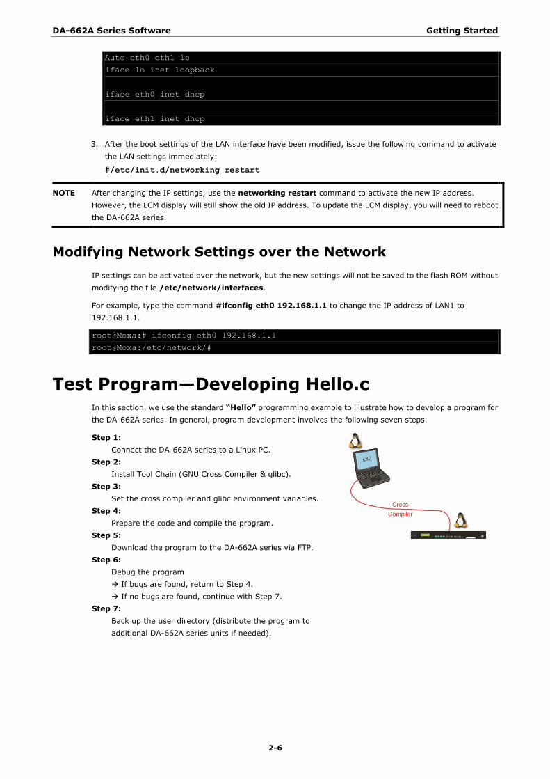
Test Program—Developing Hello.c In this section, we use the standard “Hello” programming example to illustrate how to develop a program for
the DA-662A series. In general, program development involves the following seven steps.
Step 1:
Connect the DA-662A series to a Linux PC.
Step 2:
Install Tool Chain (GNU Cross Compiler & glibc).
Step 3:
Set the cross compiler and glibc environment variables.
Step 4:
Prepare the code and compile the program.
Step 5:
Download the program to the DA-662A series via FTP.
Step 6:
Debug the program
If bugs are found, return to Step 4.
If no bugs are found, continue with Step 7.
Step 7:
Back up the user directory (distribute the program to
additional DA-662A series units if needed).
DA-662A Series Software Getting Started
2-7
Installing the Tool Chain (Linux)
The PC must have the Linux Operating System pre-installed before installing the DA-662A series GNU Tool
Chain. Redhat 7.3/8.0, Fedora core, Debian 7 and later compatible versions are recommended. The Tool Chain
requires about 1 GB of hard disk space on your PC. The DA-662A series Tool Chain software is located on the
DA-662A series CD. To install the Tool Chain, insert the CD into your PC and then issue the following
commands:
#mount /dev/cdrom /mnt/cdrom
#./mnt/cdrom/Toolchain/arm-linux_4.4.2-vX.X.X_Build_YYMMDDHH.sh
The Tool Chain will be installed automatically on your Linux PC within a few minutes. Before compiling the
program, be sure to set the following path first, since the Tool Chain files, including the compiler, link, library,
and include files are located in this directory.
#export PATH=/usr/local/arm-linux-4.4.2-v4/bin:$PATH
Setting the path allows you to run the compiler from any directory.
Checking the Flash Memory Space
The DA-662A series uses a specially designed root file system. Only the /tmp, /etc, /home, and /root
directories are writable. Others are read-only. The writable directories are mounted on /dev/mtdblock3. If
the /dev/mtdblock3 is full, you will not be able to save data to the Flash ROM. Use the following command
to calculate the amount of ―Available‖ flash memory:
/>df –h
root@Moxa:~# df -h
Filesystem Size Used Available Use% Mounted on
/dev/root 12.0M 9.2M 2.8M 77% /
devtmpfs 61.0M 0 61.0M 0% /dev
/dev/ram0 1003.0K 22.0K 930.0K 2% /var
/dev/cfa1 1.6G 1021.8M 509.9M 67% /var/cf
/dev/mtdblock3 16.0M 860.0K 15.2M 5% /tmp
/dev/mtdblock3 16.0M 860.0K 15.2M 5% /home
/dev/mtdblock3 16.0M 860.0K 15.2M 5% /etc
root@Moxa:~#
If there isn‘t enough ―Available‖ space for your application, you will need to delete some existing files. To do
this, use the console cable to connect your PC to the DA-662A series, and then use the console utility to delete
the files from the DA-662A series‘ flash memory.
Compiling Hello.c
The CD included with the product contains several example programs. Here we use Hello.c as an example to
show you how to compile and run your applications. Type the following commands from your PC to copy the
files used for this example from the CD to your computer‘s hard drive:
# cd /tmp/
# mkdir example
# cp –r /mnt/cdrom/example/* /tmp/example
To compile the program, go to the Hello subdirectory and issue the following commands:
#cd example/hello #make
DA-662A Series Software Getting Started
2-8
You should receive the following response:
[root@localhost hello]# make PREFIX=arm-none-linux-gnueabi-
arm-none-linux-gnueabi-gcc –o hello-release hello.c
arm-none-linux-gnueabi-strip –s hello-release
arm-none-linux-gnueabi-gcc –ggdb -o hello-debug hello.c
[root@localhost hello]# _
Next, execute make to generate hello-release and hello-debug, which are described below:
hello-release—an execution file (created specifically to run on the DA-662A series)
hello-debug—an GDB debug server execution file (see Chapter 5 for details about the GDB debug tool).
NOTE Be sure to type the #make command from within the /tmp/example/hello directory, since DA-662A‘s tool
chain puts a specially designed Makefile in that directory. This special Makefile uses the
arm-none-linux-gnueabi-gcc compiler to compile the hello.c source code for the Moxa Macro environment. If
you type the #make command from within any other directory, Linux will use the x86 compiler (for example,
cc or gcc).
Refer to Chapter 5 to see a Make file example.
Uploading and Running the “Hello” Program
Use the following command to upload hello-release to the DA-662A series via FTP.
1. From the PC, type:
#ftp 192.168.3.127
2. Use the bin command to set the transfer mode to Binary mode, and then use the put command to initiate
the file transfer:
ftp> bin
ftp> put hello-release
3. From the DA-662A series, type:
# chmod +x hello-release
# ./hello-release
The word Hello will be printed on the screen.
root@Moxa:~# ./hello-release
Hello
Developing Your First Application We use the tcps2 example to illustrate how to build an application. The procedure outlined in the following
subsections will show you how to build a TCP server program with serial port communication that runs on the
DA-662A series.
DA-662A Series Software Getting Started
2-9
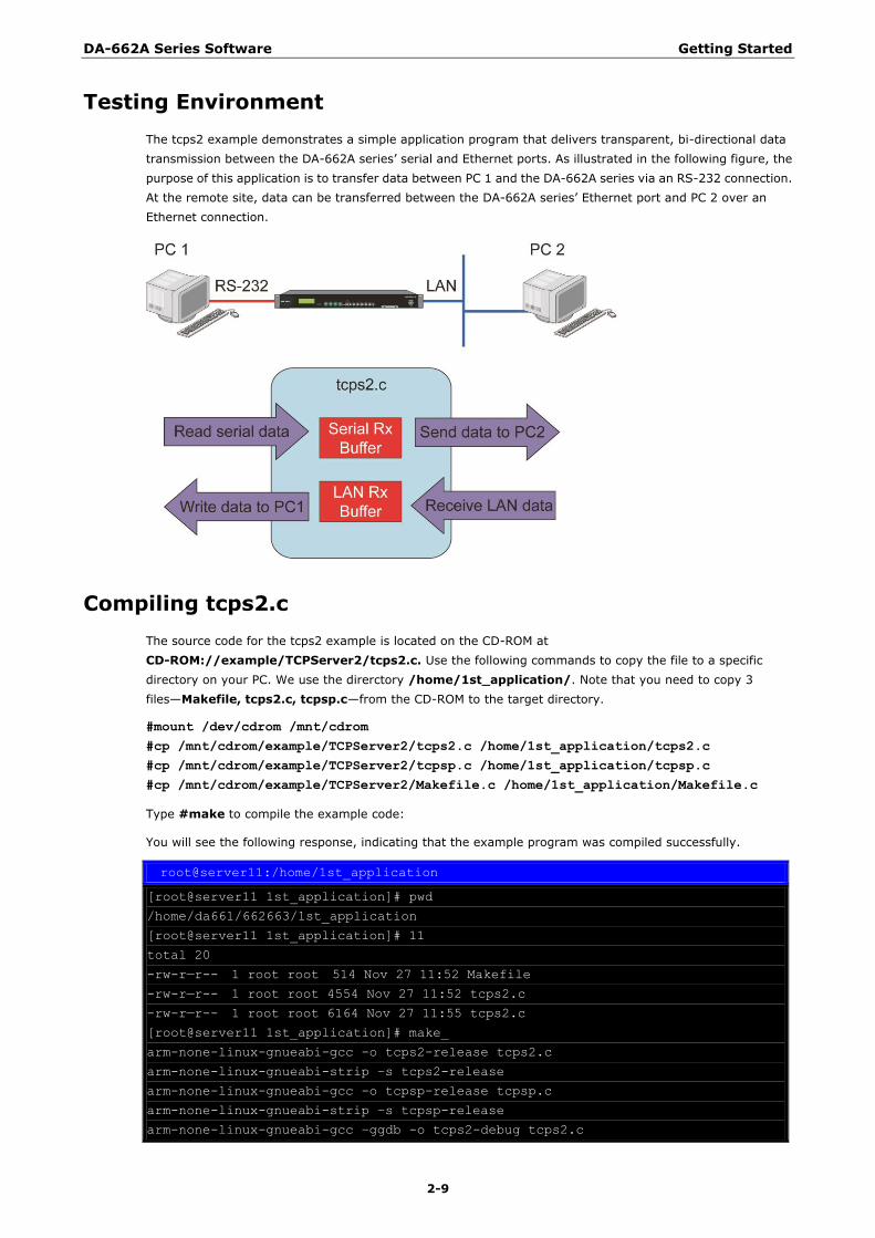
Testing Environment
The tcps2 example demonstrates a simple application program that delivers transparent, bi-directional data
transmission between the DA-662A series‘ serial and Ethernet ports. As illustrated in the following figure, the
purpose of this application is to transfer data between PC 1 and the DA-662A series via an RS-232 connection.
At the remote site, data can be transferred between the DA-662A series‘ Ethernet port and PC 2 over an
Ethernet connection.
Compiling tcps2.c
The source code for the tcps2 example is located on the CD-ROM at
CD-ROM://example/TCPServer2/tcps2.c. Use the following commands to copy the file to a specific
directory on your PC. We use the direrctory /home/1st_application/. Note that you need to copy 3
files—Makefile, tcps2.c, tcpsp.c—from the CD-ROM to the target directory.
#mount /dev/cdrom /mnt/cdrom
#cp /mnt/cdrom/example/TCPServer2/tcps2.c /home/1st_application/tcps2.c
#cp /mnt/cdrom/example/TCPServer2/tcpsp.c /home/1st_application/tcpsp.c
#cp /mnt/cdrom/example/TCPServer2/Makefile.c /home/1st_application/Makefile.c
Type #make to compile the example code:
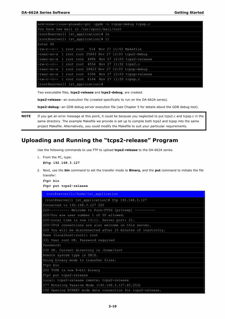
You will see the following response, indicating that the example program was compiled successfully.
root@server11:/home/1st_application
[root@server11 1st_application]# pwd
/home/da661/662663/1st_application
[root@server11 1st_application]# 11
total 20
-rw-r—r-- 1 root root 514 Nov 27 11:52 Makefile
-rw-r—r-- 1 root root 4554 Nov 27 11:52 tcps2.c
-rw-r—r-- 1 root root 6164 Nov 27 11:55 tcps2.c
[root@server11 1st_application]# make_
arm-none-linux-gnueabi-gcc -o tcps2-release tcps2.c
arm-none-linux-gnueabi-strip –s tcps2-release
arm-none-linux-gnueabi-gcc -o tcpsp-release tcpsp.c
arm-none-linux-gnueabi-strip –s tcpsp-release
arm-none-linux-gnueabi-gcc –ggdb -o tcps2-debug tcps2.c
DA-662A Series Software Getting Started
2-10
arm-none-linux-gnueabi-gcc –ggdb -o tcpsp-debug tcpsp.c
You have new mail in /var/spool/mail/root
[root@server11 1st_application]# 1s
[root@server11 1st_application]# 11
total 92
-rw-r—-r-- 1 root root 514 Nov 27 11:52 Makefile
-rwxr-xr—x 1 root root 25843 Nov 27 12:03 tcps2-debug
-rwxr—xr-x 1 root root 4996 Nov 27 12:03 tcps2-release
-rw-r—-r-- 1 root root 4554 Nov 27 11:52 tcps2.c
-rwxr—xr-x 1 root root 26823 Nov 27 12:03 tcpsp-debug
-rwxr—xr-x 1 root root 5396 Nov 27 12:03 tcpsp-release
-rw-r—-r-- 1 root root 6164 Nov 27 11:55 tcpsp.c
[root@server11 1st_application]#
Two executable files, tcps2-release and tcps2-debug, are created.
tcps2-release—an execution file (created specifically to run on the DA-662A series).
tcps2-debug—an GDB debug server execution file (see Chapter 5 for details about the GDB debug tool).
NOTE If you get an error message at this point, it could be because you neglected to put tcps2.c and tcpsp.c in the
same directory. The example Makefile we provide is set up to compile both tcps2 and tcpsp into the same
project Makefile. Alternatively, you could modify the Makefile to suit your particular requirements.
Uploading and Running the “tcps2-release” Program
Use the following commands to use FTP to upload tcps2-release to the DA-662A series.
1. From the PC, type:
#ftp 192.168.3.127
2. Next, use the bin command to set the transfer mode to Binary, and the put command to initiate the file
transfer:
ftp> bin
ftp> put tcps2-release
root@server11:/home/1st_application
[root@server11 1st_application]# ftp 192.168.3.127
Connected to 192.168.3.127 220
220---------- Welcome to Pure-FTPd [privsep] ----------
220-You are user number 1 of 50 allowed.
220-Local time is now 13:11. Server port: 21.
220-IPv6 connections are also welcome on this server.
220 You will be disconnected after 15 minutes of inactivity.
Name (localhost:root): root
331 User root OK. Password required
Password:
230 OK. Current directory is /home/root
Remote system type is UNIX.
Using binary mode to transfer files.
ftp> bin
200 TYPE is now 8-bit binary
ftp> put tcps2-release
local: tcps2-release remote: tcps2-release
277 Entering Passive Mode (192.168.3.127.82.253)
150 Opening BINARY mode data connection for tcps2-release.
DA-662A Series Software Getting Started
2-11
226 Transfer complete
4996 bytes sent in 0.00013 seconds (3.9e+04 Kbytes/s)
ftp> ls
227 Entering Passive Mode (192.168.3.127.106.196)
150 Opening ASCII mode data connection for /bin/ls.
-rw------- 1 root root 899 Jun 10 08:11 bash_history
-rw-r--r-- 1 root root 4996 Jun 12 02:15 tcps2-release
226 Transfer complete
ftp>
3. From the DA-662A series, type:
# chmod +x tcps2-release
# ./tcps2-release &
192.168.3.127 - PuTTY
root@Moxa:~# ls –al
drwxr—xr-x 2 root root 0 Jun 12 02:14
drwxr—xr-x 15 root root 0 Jan 1 1970
-rw------- 1 root root 899 Jun 10 08:11 .bash_history
-rw-r--r-- 1 root root 4996 Jun 12 02:15 tcps2-release
root@Moxa:~# chmod +x tcps2-release
root@Moxa:~# ls –al
drwxr—xr-x 2 root root 0 Jun 12 02:14
drwxr—xr-x 15 root root 0 Jan 1 1970
-rw------- 1 root root 899 Jun 10 08:11 .bash_history
-rwxr-xr-x 1 root root 4996 Jun 12 02:15 tcps2-release
root@Moxa:~#
4. The program should start running in the background. Use either the #ps command to check if the tcps2
program is actually running in the background.
#ps // use this command to check if the program is running
192.168.3.127 - PuTTY
[1]+ Running ./tcps2-release &
root@Moxa:~# ps
PID Uid VmSize Stat Command
1 root 1296 S init
2 root S [keventd]
3 root S [ksoftirqd_CPU0]
4 root S [kswapd]
5 root S [bdflush]
6 root S [kupdated]
7 root S [mtdblockd]
8 root S [khubd]
10 root S [jffs2_gcd_mtd3]
38 root 1256 S stdef
46 root 1368 S /usr/sbin/inetd
52 root 4464 S /usr/sbin/httpd
53 nobody 4480 S /usr/sbin/httpd
54 nobody 4480 S /usr/sbin/httpd
64 nobody 4480 S /usr/sbin/httpd
65 nobody 4480 S /usr/sbin/httpd
66 nobody 4480 S /usr/sbin/httpd
88 bin 1460 S /sbin/portmap
100 root 1556 S /usr/sbin/rpc.statd
DA-662A Series Software Getting Started
2-12
104 root 4044 S /usr/sbin/snmpd –s –l /dev/null
106 root 2832 S /usr/sbin/snmptrapd -s
135 root 1364 S /sbin/cardmgr
139 root 1756 S /usr/sbin/rpc.nfsd
141 root 1780 S /usr/sbin/rpc.mountd
148 root 2960 S /usr/sbin/sshd
156 root 1272 S /bin/reportip
157 root 1532 S /sbin/getty 115200 ttyS0
158 root 1532 S /sbin/getty 115200 ttyS1
162 root 3652 S /usr/sbin/sshd
163 root 2208 S -bash
169 root 2192 S ftpd: 192.168.3.110: root: IDLE
187 root 1264 S ./tcps2-release
188 root 1592 S ps
root@Moxa:~#
NOTE Use the kill -9 command for PID 187 to terminate this program: #kill -9 187
Testing Procedure Summary
1. Compile tcps2.c (#make).
2. Upload and run tcps2-release in the background (#./tcps2-release &).
3. Check that the process is running (#ps).
4. Use a serial cable to connect PC1 to the DA-662A series‘ serial port 1.
5. Use an Ethernet cable to connect PC2 to the DA-662A series.
6. On PC1: If running Windows, use HyperTerminal (38400, n, 8, 1) to open COMn.
7. On PC2: Type #telnet 192.168.3.127 4001.
8. On PC1: Type some text on the keyboard and then press Enter.
9. On PC2: The text you typed on PC1 will appear on PC2‘s screen.
The testing environment is illustrated in the following figure. However, note that there are limitations to the
example program tcps2.c.
DA-662A Series Software Getting Started
2-13
NOTE The tcps2.c application is a simple example designed to give users a basic understanding of the concepts
involved in combining Ethernet communication and serial port communication. However, the example program
has some limitations that make it unsuitable for real-life applications.
1. The serial port is in canonical mode and block mode, making it impossible to send data from the Ethernet
side to the serial side (i.e., from PC 2 to PC 1 in the above example).
2. The Ethernet side will not accept multiple connections.
3 3. Managing Embedded Linux
This chapter includes information about version control, deployment, updates, and peripherals. The
information in this chapter will be particularly useful when you need to run the same application on several
DA-662A series units.
The following topics are covered in this chapter:
System Version Information
Upgrading the Firmware
Loading Factory Defaults
Enabling and Disabling Daemons
Setting the Run-level
Adjusting the System Time
Setting the Time Manually
NTP Client
Updating the Time Automatically
Cron—Daemon for Executing Scheduled Commands
Connecting Peripherals
USB Mass Storage
CF Mass Storage
DA-662A Series Software Managing Embedded Linux
3-2
System Version Information To determine the hardware capability of your DA-662A series, and what kind of software functions are
supported, check the version numbers of your DA-662A series‘ firmware version. Contact Moxa to determine
the hardware version. You will need the Production S/N (Serial number), which is located on the DA-662A
series‘ bottom label. To check the kernel version, type:
#kversion
192.168.3.127 - PuTTY
root@Moxa:~# kversion
DA-662A-16-LX version 1.0
root@Moxa:~#
Upgrading the Firmware
The DA-662A series‘ BIOS, kernel, and user file system are combined into one firmware file, which can be
downloaded from Moxa‘s website (www.moxa.com). The name of the file has the form
FWR_DA662A_Vx.x_Build_YYMMDDHH.hfm, with ―x.x.x‖ indicating the firmware version. To upgrade the
firmware, download the firmware file to a PC, and then transfer the file to the DA-662A series unit via a serial
Console or Telnet Console connection.
ATTENTION
Upgrading the firmware will erase all data on the Flash ROM
If you are using the ramdisk to store code for your applications, beware that updating the firmware will erase
all of the data on the Flash ROM. You should back up your application files and data before updating the
firmware.
Since different Flash disks have different sizes, it‘s a good idea to check the size of your Flash disk before
upgrading the firmware, or before using the disk to store your application and data files. Use the #df –h
command to list the size of each memory block, and how much free space is available in each block.
192.168.3.127 - PuTTY
root@Moxa:/# df –h
Filesystem Size Used Available Use% Mounted on
/dev/root 12.0M 9.2M 2.8M 77% /
devtmpfs 61.0M 0 61.0M 0% /dev
/dev/ram0 1003.0K 22.0K 930.0K 2% /var
/dev/cfa1 1.6G 1021.8M 509.9M 67% /var/cf
/dev/mtdblock3 16.0M 860.0K 15.2M 5% /tmp
/dev/mtdblock3 16.0M 860.0K 15.2M 5% /home
/dev/mtdblock3 16.0M 860.0K 15.2M 5% /etc
root@Moxa:/# upramdisk
root@Moxa:/# df -h
Filesystem Size Used Available Use% Mounted on
/dev/root 12.0M 9.2M 2.8M 77% /
devtmpfs 61.0M 0 61.0M 0% /dev
/dev/ram0 1003.0K 23.0K 929.0K 2% /var
/dev/cfa1 1.6G 1021.8M 509.9M 67% /var/cf
/dev/mtdblock3 16.0M 860.0K 15.2M 5% /tmp
/dev/mtdblock3 16.0M 860.0K 15.2M 5% /home
/dev/mtdblock3 16.0M 860.0K 15.2M 5% /etc
/dev/ram1 15.5M 128.0K 14.6M 1% /var/ramdisk
root@Moxa:/# cd /mnt/ramdisk/
root@Moxa:/mnt/ramdisk#
DA-662A Series Software Managing Embedded Linux
3-3
The following instructions give the steps required to save the firmware file to the DA-662A series‘ RAM disk, and
then upgrade the firmware.
1. Type the following commands to enable the RAM disk:
#upramdisk
#cd /mnt/ramdisk
2. Type the following commands to use the DA-662A series‘ built-in FTP client to transfer the firmware file
(FWR_DA662A_Vx.x_Build_YYMMDDHH.hfm) from the PC to the DA-662A series:
/mnt/ramdisk> ftp <destination PC‟s IP> Login Name: xxxx
Login Password: xxxx
ftp> bin
ftp> get FWR_DA662A_Vx.x_Build_YYMMDDHH.hfm
192.168.3.127 - PuTTY
root@Moxa:/mnt/ramdisk# ftp 192.168.3.193
Connected to 192.168.3.193 (192.168.3.193).
220 TYPSoft FTP Server 1.10 ready…
Name (192.168.3.193:root): root
331 Password required for root.
Password:
230 User root logged in.
Remote system type is UNIX.
Using binary mode to transfer files.
ftp> cd newsw
250 CWD command successful. ―/C:/ftproot/newsw/‖ is current directory.
ftp> bin
200 Type set to I.
ftp> ls
200 Port command successful.
150 Opening data connection for directory list.
drw-rw-rw- 1 ftp ftp 0 Nov 30 10:03 .
drw-rw-rw- 1 ftp ftp 0 Nov 30 10:03 .
-rw-rw-rw- 1 ftp ftp 12904012 Nov 29 10:24 FWR_DA662A_Vx.x_Build_YYMMDDHH.hfm
226 Transfer complete.
ftp> get FWR_DA662A_Vx.x_Build_YYMMDDHH.hfm
local: FWR_DA662A_Vx.x_Build_YYMMDDHH.hfm remote:
FWR_DA662A_Vx.x_Build_YYMMDDHH.hfm
200 Port command successful.
150 Opening data connection for FWR_DA662A_Vx.x_Build_YYMMDDHH.hfm
226 Transfer complete.
12904012 bytes received in 2.17 secs (5925.8 kB/s)
ftp>
3. Next, use the upfirm command to upgrade the kernel and root file system:
#upgradehfm FWR_DA662A_Vx.x_Build_YYMMDDHH.hfm
192.168.3.127 - PuTTY
root@Moxa:/mnt/ramdisk# upgradehfm FWR_DA662A_Vx.x_Build_YYMMDDHH.hfm
Moxa DA-662A upgrade firmware utility version 1.1.
To check source firmware file context.
The source firmware file conext is OK.
This step will upgrade firmware. All the data on flash will be destroyed.
Do you want to continue? (Y/N) :
Now upgrade the file [redboot].
Format MTD device [/dev/mtd0] ...
DA-662A Series Software Managing Embedded Linux
3-4
MTD device [/dev/mtd0] erase 128 Kibyte @ 60000 -- 100% complete.
Wait to write file ...
Completed 100%
Now upgrade the file [kernel].
Format MTD device [/dev/mtd1] ...
MTD device [/dev/mtd1] erase 128 Kibyte @ 1a0000 -- 100% complete.
Wait to write file ...
Completed 100%
Now upgrade the file [root-file-system].
Format MTD device [/dev/mtd2] ...
MTD device [/dev/mtd2] erase 128 Kibyte @ e00000 -- 100% complete.
Wait to write file ...
Completed 100%
Now upgrade the file [directory].
Format MTD device [/dev/mtd5] ...
MTD device [/dev/mtd5] erase 128 Kibyte @ 20000 -- 100% complete.
Wait to write file ...
Completed 100% Now upgrade the new configuration file.
Upgrade the firmware is OK. Rebooting
Loading Factory Defaults
To load the system‘s factory default settings, press the reset button for at least 5 seconds. Doing so will destroy
all of the files in the /home and /etc directories. While holding the button for the first 5 seconds, the ready
LED will blink once each second. After holding the button continuously for more than 5 seconds, the ready LED
will switch off, indicating that the factory defaults have been loaded.
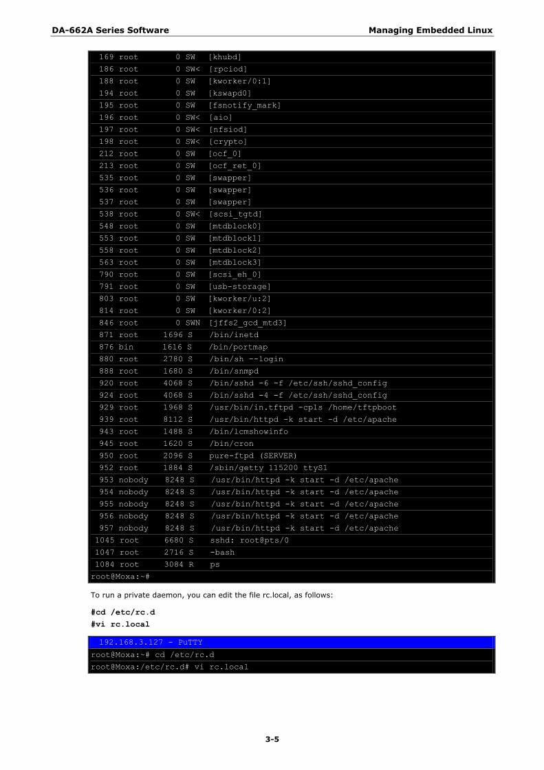
Enabling and Disabling Daemons The following daemons are enabled when the DA-662A series boots up for the first time.
snmpd SNMP Agent daemon
telnetd Telnet Server / Client daemon
inetd Internet Daemons
ftpd FTP Server / Client daemon
sshd Secure Shell Server daemon
httpd Apache WWW Server daemon
Type the command ps to list all processes currently running.
192.168.3.127 - PuTTY
root@Moxa:~# cd /etc
root@Moxa:~# ps
PID USER VSZ STAT COMMAND
1 root 1632 S init [3]
2 root 0 SW [kthreadd]
3 root 0 SW [ksoftirqd/0]
5 root 0 SW [kworker/u:0]
6 root 0 SW [rcu_kthread]
7 root 0 SW< [khelper]
155 root 0 SW [sync_supers]
157 root 0 SW [bdi-default]
158 root 0 SW< [kintegrityd]
160 root 0 SW< [kblockd]
DA-662A Series Software Managing Embedded Linux
3-5
169 root 0 SW [khubd]
186 root 0 SW< [rpciod]
188 root 0 SW [kworker/0:1]
194 root 0 SW [kswapd0]
195 root 0 SW [fsnotify_mark]
196 root 0 SW< [aio]
197 root 0 SW< [nfsiod]
198 root 0 SW< [crypto]
212 root 0 SW [ocf_0]
213 root 0 SW [ocf_ret_0]
535 root 0 SW [swapper]
536 root 0 SW [swapper]
537 root 0 SW [swapper]
538 root 0 SW< [scsi_tgtd]
548 root 0 SW [mtdblock0]
553 root 0 SW [mtdblock1]
558 root 0 SW [mtdblock2]
563 root 0 SW [mtdblock3]
790 root 0 SW [scsi_eh_0]
791 root 0 SW [usb-storage]
803 root 0 SW [kworker/u:2]
814 root 0 SW [kworker/0:2]
846 root 0 SWN [jffs2_gcd_mtd3]
871 root 1696 S /bin/inetd
876 bin 1616 S /bin/portmap
880 root 2780 S /bin/sh --login
888 root 1680 S /bin/snmpd
920 root 4068 S /bin/sshd -6 -f /etc/ssh/sshd_config
924 root 4068 S /bin/sshd -4 -f /etc/ssh/sshd_config
929 root 1968 S /usr/bin/in.tftpd -cpls /home/tftpboot
939 root 8112 S /usr/bin/httpd -k start -d /etc/apache
943 root 1488 S /bin/lcmshowinfo
945 root 1620 S /bin/cron
950 root 2096 S pure-ftpd (SERVER)
952 root 1884 S /sbin/getty 115200 ttyS1
953 nobody 8248 S /usr/bin/httpd -k start -d /etc/apache
954 nobody 8248 S /usr/bin/httpd -k start -d /etc/apache
955 nobody 8248 S /usr/bin/httpd -k start -d /etc/apache
956 nobody 8248 S /usr/bin/httpd -k start -d /etc/apache
957 nobody 8248 S /usr/bin/httpd -k start -d /etc/apache
1045 root 6680 S sshd: root@pts/0
1047 root 2716 S -bash
1084 root 3084 R ps
root@Moxa:~#
To run a private daemon, you can edit the file rc.local, as follows:
#cd /etc/rc.d
#vi rc.local
192.168.3.127 - PuTTY
root@Moxa:~# cd /etc/rc.d
root@Moxa:/etc/rc.d# vi rc.local
DA-662A Series Software Managing Embedded Linux
3-6
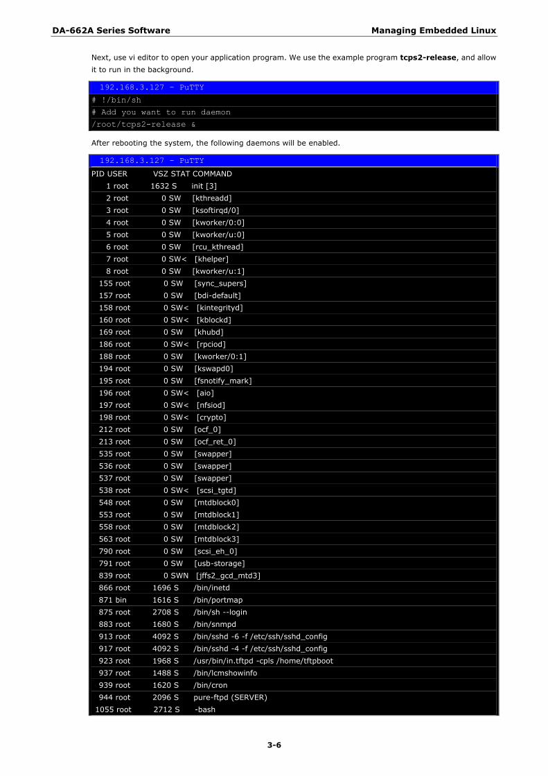
Next, use vi editor to open your application program. We use the example program tcps2-release, and allow
it to run in the background.
192.168.3.127 - PuTTY
# !/bin/sh
# Add you want to run daemon
/root/tcps2-release &
After rebooting the system, the following daemons will be enabled.
192.168.3.127 - PuTTY
PID USER VSZ STAT COMMAND
1 root 1632 S init [3]
2 root 0 SW [kthreadd]
3 root 0 SW [ksoftirqd/0]
4 root 0 SW [kworker/0:0]
5 root 0 SW [kworker/u:0]
6 root 0 SW [rcu_kthread]
7 root 0 SW< [khelper]
8 root 0 SW [kworker/u:1]
155 root 0 SW [sync_supers]
157 root 0 SW [bdi-default]
158 root 0 SW< [kintegrityd]
160 root 0 SW< [kblockd]
169 root 0 SW [khubd]
186 root 0 SW< [rpciod]
188 root 0 SW [kworker/0:1]
194 root 0 SW [kswapd0]
195 root 0 SW [fsnotify_mark]
196 root 0 SW< [aio]
197 root 0 SW< [nfsiod]
198 root 0 SW< [crypto]
212 root 0 SW [ocf_0]
213 root 0 SW [ocf_ret_0]
535 root 0 SW [swapper]
536 root 0 SW [swapper]
537 root 0 SW [swapper]
538 root 0 SW< [scsi_tgtd]
548 root 0 SW [mtdblock0]
553 root 0 SW [mtdblock1]
558 root 0 SW [mtdblock2]
563 root 0 SW [mtdblock3]
790 root 0 SW [scsi_eh_0]
791 root 0 SW [usb-storage]
839 root 0 SWN [jffs2_gcd_mtd3]
866 root 1696 S /bin/inetd
871 bin 1616 S /bin/portmap
875 root 2708 S /bin/sh --login
883 root 1680 S /bin/snmpd
913 root 4092 S /bin/sshd -6 -f /etc/ssh/sshd_config
917 root 4092 S /bin/sshd -4 -f /etc/ssh/sshd_config
923 root 1968 S /usr/bin/in.tftpd -cpls /home/tftpboot
937 root 1488 S /bin/lcmshowinfo
939 root 1620 S /bin/cron
944 root 2096 S pure-ftpd (SERVER)
1055 root 2712 S -bash
DA-662A Series Software Managing Embedded Linux
3-7
1157 root 21136 S /usr/bin/httpd -k start -d /etc/apache
1159 nobody 21556 S /usr/bin/httpd -k start -d /etc/apache
1160 nobody 21276 S /usr/bin/httpd -k start -d /etc/apache
1161 nobody 21276 S /usr/bin/httpd -k start -d /etc/apache
1162 nobody 21556 S /usr/bin/httpd -k start -d /etc/apache
1163 nobody 21556 S /usr/bin/httpd -k start -d /etc/apache
1179 nobody 21136 S /usr/bin/httpd -k start -d /etc/apache
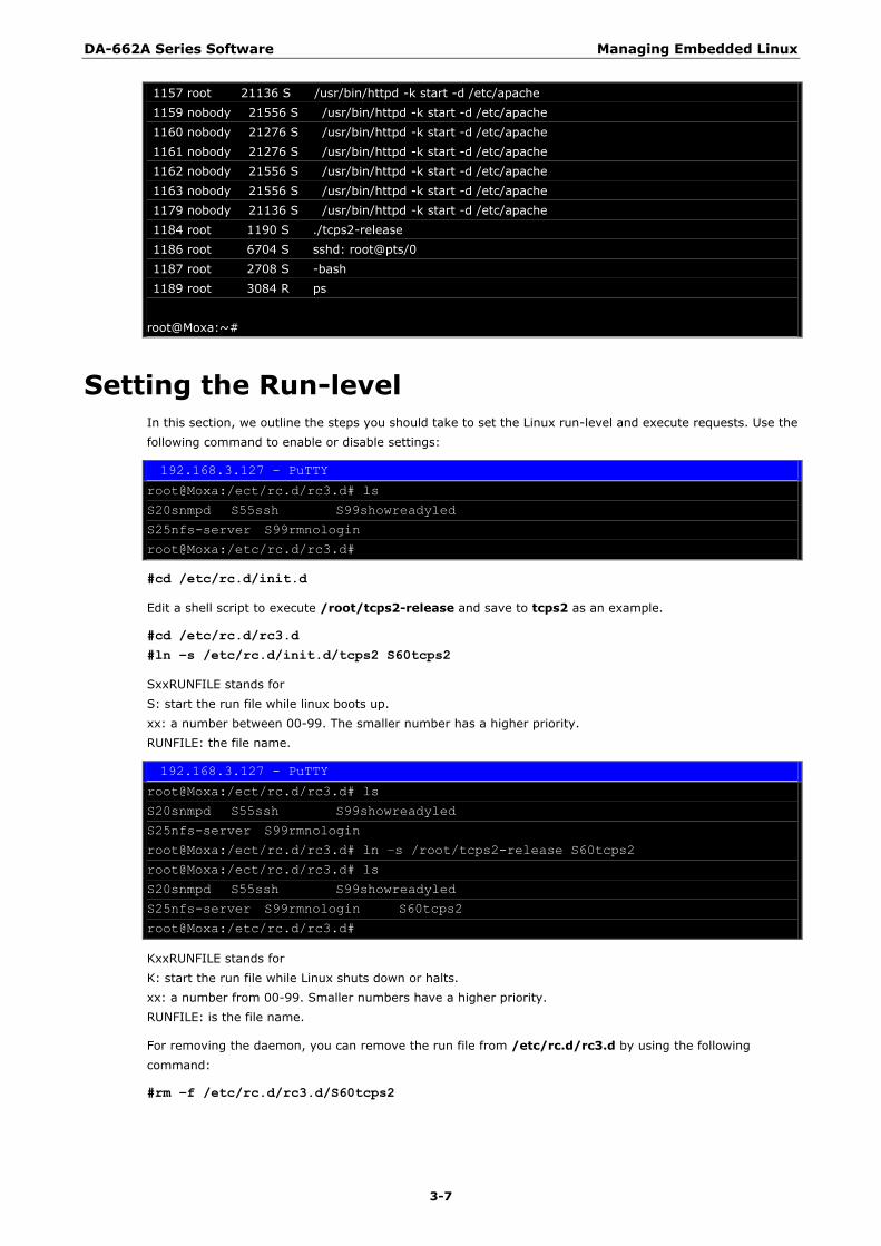
1184 root 1190 S ./tcps2-release
1186 root 6704 S sshd: root@pts/0
1187 root 2708 S -bash
1189 root 3084 R ps
root@Moxa:~#
Setting the Run-level In this section, we outline the steps you should take to set the Linux run-level and execute requests. Use the
following command to enable or disable settings:
192.168.3.127 - PuTTY
root@Moxa:/ect/rc.d/rc3.d# ls
S20snmpd S55ssh S99showreadyled
S25nfs-server S99rmnologin
root@Moxa:/etc/rc.d/rc3.d#
#cd /etc/rc.d/init.d
Edit a shell script to execute /root/tcps2-release and save to tcps2 as an example.
#cd /etc/rc.d/rc3.d
#ln –s /etc/rc.d/init.d/tcps2 S60tcps2
SxxRUNFILE stands for
S: start the run file while linux boots up.
xx: a number between 00-99. The smaller number has a higher priority.
RUNFILE: the file name.
192.168.3.127 - PuTTY
root@Moxa:/ect/rc.d/rc3.d# ls
S20snmpd S55ssh S99showreadyled
S25nfs-server S99rmnologin
root@Moxa:/ect/rc.d/rc3.d# ln –s /root/tcps2-release S60tcps2
root@Moxa:/ect/rc.d/rc3.d# ls
S20snmpd S55ssh S99showreadyled
S25nfs-server S99rmnologin S60tcps2
root@Moxa:/etc/rc.d/rc3.d#
KxxRUNFILE stands for
K: start the run file while Linux shuts down or halts.
xx: a number from 00-99. Smaller numbers have a higher priority.
RUNFILE: is the file name.
For removing the daemon, you can remove the run file from /etc/rc.d/rc3.d by using the following
command:
#rm –f /etc/rc.d/rc3.d/S60tcps2
DA-662A Series Software Managing Embedded Linux
3-8
Adjusting the System Time
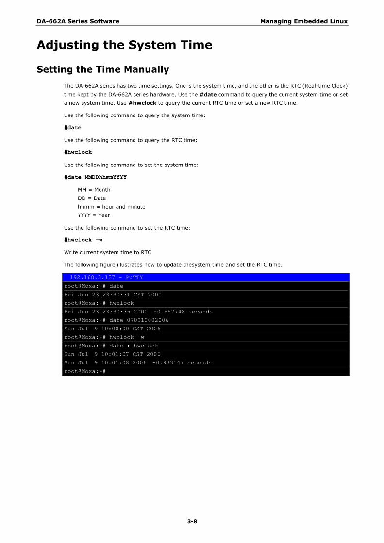
Setting the Time Manually
The DA-662A series has two time settings. One is the system time, and the other is the RTC (Real-time Clock)
time kept by the DA-662A series hardware. Use the #date command to query the current system time or set
a new system time. Use #hwclock to query the current RTC time or set a new RTC time.
Use the following command to query the system time:
#date
Use the following command to query the RTC time:
#hwclock
Use the following command to set the system time:
#date MMDDhhmmYYYY
MM = Month
DD = Date
hhmm = hour and minute
YYYY = Year
Use the following command to set the RTC time:
#hwclock –w
Write current system time to RTC
The following figure illustrates how to update thesystem time and set the RTC time.
192.168.3.127 - PuTTY
root@Moxa:~# date
Fri Jun 23 23:30:31 CST 2000
root@Moxa:~# hwclock
Fri Jun 23 23:30:35 2000 -0.557748 seconds
root@Moxa:~# date 070910002006
Sun Jul 9 10:00:00 CST 2006
root@Moxa:~# hwclock –w
root@Moxa:~# date ; hwclock
Sun Jul 9 10:01:07 CST 2006
Sun Jul 9 10:01:08 2006 -0.933547 seconds
root@Moxa:~#
DA-662A Series Software Managing Embedded Linux
3-9
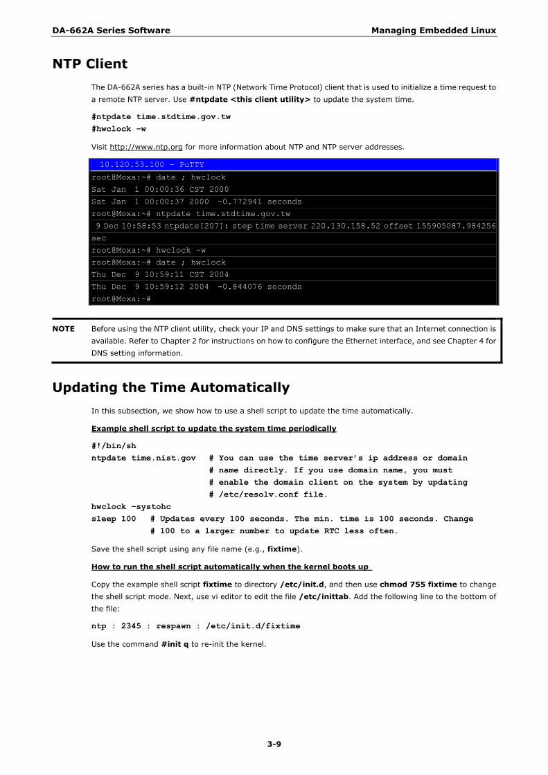
NTP Client
The DA-662A series has a built-in NTP (Network Time Protocol) client that is used to initialize a time request to
a remote NTP server. Use #ntpdate <this client utility> to update the system time.
#ntpdate time.stdtime.gov.tw
#hwclock –w
Visit http://www.ntp.org for more information about NTP and NTP server addresses.
10.120.53.100 - PuTTY
root@Moxa:~# date ; hwclock
Sat Jan 1 00:00:36 CST 2000
Sat Jan 1 00:00:37 2000 -0.772941 seconds
root@Moxa:~# ntpdate time.stdtime.gov.tw
9 Dec 10:58:53 ntpdate[207]: step time server 220.130.158.52 offset 155905087.984256
sec
root@Moxa:~# hwclock –w
root@Moxa:~# date ; hwclock
Thu Dec 9 10:59:11 CST 2004
Thu Dec 9 10:59:12 2004 -0.844076 seconds
root@Moxa:~#
NOTE Before using the NTP client utility, check your IP and DNS settings to make sure that an Internet connection is
available. Refer to Chapter 2 for instructions on how to configure the Ethernet interface, and see Chapter 4 for
DNS setting information.
Updating the Time Automatically
In this subsection, we show how to use a shell script to update the time automatically.
Example shell script to update the system time periodically
#!/bin/sh
ntpdate time.nist.gov # You can use the time server‟s ip address or domain
# name directly. If you use domain name, you must
# enable the domain client on the system by updating
# /etc/resolv.conf file.
hwclock –systohc
sleep 100 # Updates every 100 seconds. The min. time is 100 seconds. Change
# 100 to a larger number to update RTC less often.
Save the shell script using any file name (e.g., fixtime).
How to run the shell script automatically when the kernel boots up
Copy the example shell script fixtime to directory /etc/init.d, and then use chmod 755 fixtime to change
the shell script mode. Next, use vi editor to edit the file /etc/inittab. Add the following line to the bottom of
the file:
ntp : 2345 : respawn : /etc/init.d/fixtime
Use the command #init q to re-init the kernel.
DA-662A Series Software Managing Embedded Linux
3-10
Cron—Daemon for Executing Scheduled
Commands Start Cron from the directory /etc/rc.d/rc.local. It will return immediately, so you don‘t need to start it with ‗&‘
to run in the background.
The Cron daemon will search /etc/cron.d/crontab for crontab files, which are named after accounts in
/etc/passwd.
Cron wakes up every minute, and checks each command to see if it should be run in the current minute.
Modify the file /etc/cron.d/crontab to set up your scheduled applications. Crontab files have the following
format:
mm hh dom mon dow user command
min hour date month week user command
0-59 0-23 1-31 1-12 0-6 (0 is Sunday)
The following example demonstrates how to use Cron.
How to use cron to update the system time and RTC time every day at 8:00.
STEP1: Write a shell script named fixtime.sh and save it to /home/.
#!/bin/sh
ntpdate time.nist.gov
hwclock –-systohc
exit 0
STEP2: Change mode of fixtime.sh
#chmod 755 fixtime.sh
STEP3: Modify /etc/cron.d/crontab file to run fixtime.sh at 8:00 every day.
Add the following line to the end of crontab:
* 8 * * * root /home/fixtime.sh
STEP4: Enable the cron daemon manually.
#/etc/init.d/cron start
STEP5: Enable cron when the system boots up.
Add the following line in the file /etc/rc.d/rc.local
#/etc/init.d/cron start
DA-662A Series Software Managing Embedded Linux
3-11
Connecting Peripherals
USB Mass Storage
The DA-662A series supports PNP (plug-n-play), and hot pluggability for connecting USB mass storage devices.
The DA-662A series has a built-in auto mount utility that eases the mounting procedure. The first USB mass
storage device to be connected will be mounted automatically by mount to /mnt/sdc, and the second device
will be mounted automatically to /mnt/sdd. The DA-662A series will be un-mounted automatically with the
umount command when the device is disconnected.
ATTENTION
Remember to type the #sync command before you disconnect the USB mass storage device. If you don‘t issue
the command, you may lose some data.
Remember to exit the /mnt/sdc or /mnt/sdd directory when you disconnect the USB mass storage device.
If you stay in /mnt/sdc or /mnt/ sdd, the auto un-mount process will fail. If that happens, type #umount
/mnt/sdc to un-mount the USB device manually.
The DA-662A series only supports certain types of flash disk USB mass storage devices. The Following USB
flash disks are supported:
• San Sandisk Cruzer mini 128MB
• Sandisk Cruzer Crossfire 1GB
• Sandisk Cruzer mini 2GB
• Intel Flash Memory 128MB
• Abocom 128MB
• PQI 256MB
• Transcend JetFlash 1G
• Transcend JetFlash 128MB
• Transcend JetFlash V30 1GB
• Transcend JetFlash V30 2GB
• ADATA My Flash 1G
• ADATA My Flash 2G
Some USB flash disks and hard disks may not be compatible with the DA-662A series. Check compatibility
issues before you purchase a USB device to connect to the DA-662A series.
CF Mass Storage
The DA-662A series embedded computers do not support CompactFlash hot swap and PnP (Plug and Play)
functions. You must disconnect the power source first before inserting or removing the CompactFlash card.
Although the DA-662A series CF slot does not support PNP, the slot has a built-in auto mount utility to make the
mount procedure easier. The CF mass storage device will be mounted automatically by the mount command to
/mnt/cf.
4 4. Managing Communications
In this chapter, we explain how to configure the DA-662A series‘ various communication functions.
The following topics are covered in this chapter:
Telnet / FTP
DNS
Web Service—Apache
IPTABLES
NAT
NAT Example
Enabling NAT at Bootup
Dial-up Service—PPP
PPPoE
NFS (Network File System)
Setting up the DA-662A series as an NFS Client
SNMP
DA-662A Series Software Managing Communications
4-2
Telnet / FTP In addition to supporting Telnet client/server and FTP client/server, the DA-662A series also supports SSH and
sftp client/server. To enable or disable the Telnet, you first need to edit the file /etc/inetd.conf.
Enabling the Telnet
The following example shows the default content of the file /etc/inetd.conf. The default is to enable the
Telnet server:
discard dgram udp wait root /bin/discard
discard stream tcp nowait root /bin/discard
#ftp stream tcp6 nowait root /sbin/pure-ftpd -H -g /var/run/ftpd.pid
telnet stream tcp6 nowait root /bin/telnetd
Disabling the Telnet
Disable the daemon by typing ‗#‘ in front of the first character of the row to comment out the line and reboot
the computer.
To enable or disable the FTP server, use the following commands:
Enabling the FTP server
#cd /etc/rc.d/rc3.d
#ln -s /etc/rc.d/init.d/pure-ftpd S99pure-ftpd
NOTE By default, the FTP server is enabled. You do not need to change the configuration to use the FTP server to
transfer files.
Disabling the FTP server,
Removing the run file from /etc/rc.d/rc3.d by using the following command:
#rm -f /etc/rc.d/rc3.d/S99pure-ftpd
DNS The DA-662A series support DNS client (but not DNS server). To set up DNS client, you need to edit three
configuration files: /etc/hosts, /etc/resolv.conf, and /etc/nsswitch.conf.
/etc/hosts
This is the first file that the Linux system reads to resolve the host name and IP address.
/etc/resolv.conf
This is the most important file that you need to edit when using DNS for the other programs. For example,
before using #ntpdate time.nist.goc to update the system time, you will need to add the DNS server address
to the file. Ask your network administrator which DNS server address you should use. The DNS server‘s IP
address is specified with the ―nameserver‖ command. For example, add the following line to /etc/resolv.conf
if the DNS server‘s IP address is 168.95.1.1:
nameserver 168.95.1.1
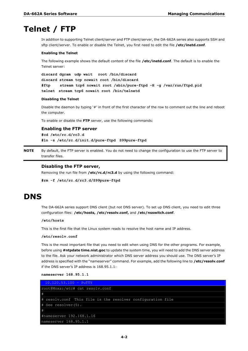
10.120.53.100 - PuTTY
root@Moxa:/etc# cat resolv.conf
#
# resolv.conf This file is the resolver configuration file
# See resolver(5).
#
#nameserver 192.168.1.16
nameserver 168.95.1.1
DA-662A Series Software Managing Communications
4-3
nameserver 140.115.1.31
nameserver 140.115.236.10
root@Moxa:/etc#
/etc/nsswitch.conf
This file defines the sequence to resolve the IP address by using /etc/hosts file or /etc/resolv.conf.
Web Service—Apache The Apache web server‘s main configuration file is /etc/apache/conf/httpd.conf, with the default
homepage located at /home/httpd/htdocs/index.html. Save your own homepage to the following
directory:
/home/httpd/html/
Save your CGI page to the following directory:
/home/httpd/cgi-bin/
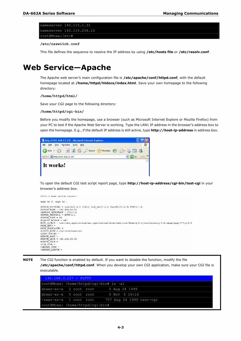
Before you modify the homepage, use a browser (such as Microsoft Internet Explore or Mozilla Firefox) from
your PC to test if the Apache Web Server is working. Type the LAN1 IP address in the browser‘s address box to
open the homepage. E.g., if the default IP address is still active, type http://host-ip-address in address box.
To open the default CGI test script report page, type http://host-ip-address/cgi-bin/test-cgi in your
browser‘s address box.
NOTE The CGI function is enabled by default. If you want to disable the function, modify the file
/etc/apache/conf/httpd.conf. When you develop your own CGI application, make sure your CGI file is
executable.
192.168.3.127 - PuTTY
root@Moxa: /home/httpd/cgi-bin# ls –al
drwxr—xr-x 2 root root 0 Aug 24 1999
drwxr—xr-x 5 root root 0 Nov 5 16:16
-rwxr—xr-x 1 root root 757 Aug 24 1999 test-cgi
root@Moxa: /home/httpd/cgi-bin#
DA-662A Series Software Managing Communications
4-4
IPTABLES IPTABLES is an administrative tool for setting up, maintaining, and inspecting the Linux kernel‘s IP packet filter
rule tables. Several different tables are defined, with each table containing built-in chains and user-defined
chains.
Each chain is a list of rules that apply to a certain type of packet. Each rule specifies what to do with a matching
packet. A rule (such as a jump to a user-defined chain in the same table) is called a “target”.
DA-662A series supports 3 types of IPTABLES table: Filter tables, NAT tables, and Mangle tables:
A. Filter Table—includes three chains:
INPUT chain
OUTPUT chain
FORWARD chain
B. NAT Table—includes three chains:
PREROUTING chain—transfers the destination IP address (DNAT)
POSTROUTING chain—works after the routing process and before the Ethernet device process to transfer
the source IP address (SNAT)
OUTPUT chain—produces local packets
sub-tables
Source NAT (SNAT)—changes the first source packet IP address
Destination NAT (DNAT)—changes the first destination packet IP address
MASQUERADE—a special form for SNAT. If one host can connect to internet, then other computers
that connect to this host can connect to the Internet when it the computer does not have an actual
IP address.
REDIRECT—a special form of DNAT that re-sends packets to a local host independent of the
destination IP address.
C. Mangle Table—includes two chains
PREROUTING chain—pre-processes packets before the routing process.
OUTPUT chain—processes packets after the routing process.
It has three extensions—TTL, MARK, TOS.
DA-662A Series Software Managing Communications
4-5
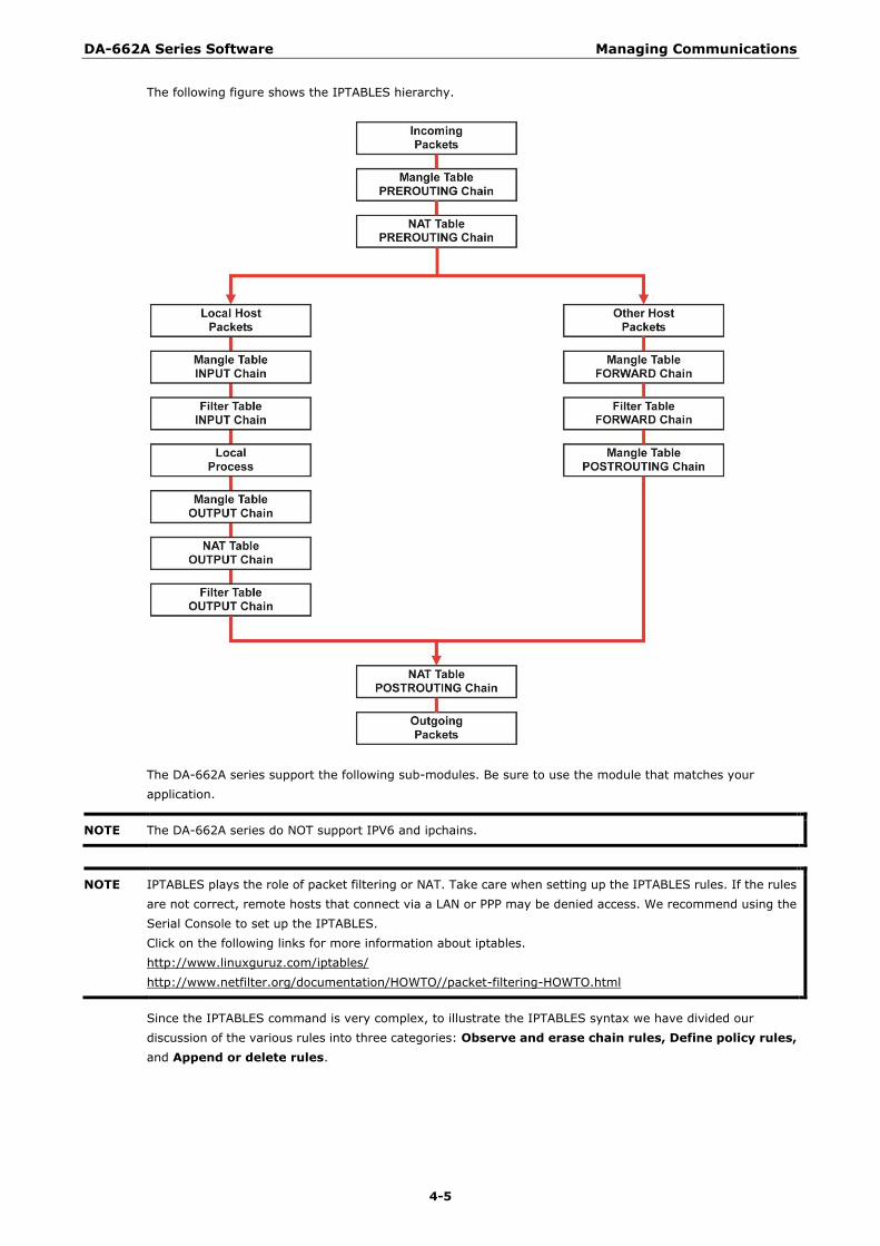
The following figure shows the IPTABLES hierarchy.
The DA-662A series support the following sub-modules. Be sure to use the module that matches your
application.
NOTE The DA-662A series do NOT support IPV6 and ipchains.
NOTE IPTABLES plays the role of packet filtering or NAT. Take care when setting up the IPTABLES rules. If the rules
are not correct, remote hosts that connect via a LAN or PPP may be denied access. We recommend using the
Serial Console to set up the IPTABLES.
Click on the following links for more information about iptables.
http://www.linuxguruz.com/iptables/
http://www.netfilter.org/documentation/HOWTO//packet-filtering-HOWTO.html
Since the IPTABLES command is very complex, to illustrate the IPTABLES syntax we have divided our
discussion of the various rules into three categories: Observe and erase chain rules, Define policy rules,
and Append or delete rules.
DA-662A Series Software Managing Communications
4-6
Observe and erase chain rules
Usage:
# iptables [-t tables] [-L] [-n]
-t tables: Table to manipulate (default: ‗filter‘); example: nat or filter.
-L [chain]: List List all rules in selected chains. If no chain is selected, all chains are listed.
-n: Numeric output of addresses and ports.
# iptables [-t tables] [-FXZ]
-F: Flush the selected chain (all the chains in the table if none is listed).
-X: Delete the specified user-defined chain.
-Z: Set the packet and byte counters in all chains to zero.
Examples:
# iptables -L -n
In this example, since we do not use the -t parameter, the system uses the default ‗filter‘ table. Three chains
are included: INPUT, OUTPUT, and FORWARD. INPUT chains are accepted automatically, and all connections
are accepted without being filtered.
#iptables –F
#iptables –X
#iptables -Z
Define policy for chain rules
Usage:
# iptables [-t tables] [-P] [INPUT, OUTPUT, FORWARD, PREROUTING, OUTPUT, POSTROUTING]
[ACCEPT, DROP]
-P: Set the policy for the chain to the given target.
INPUT: For packets coming into the DA-662A series.
OUTPUT: For locally-generated packets.
FORWARD: For packets routed out through the DA-662A series.
PREROUTING: To alter packets as soon as they come in.
POSTROUTING: To alter packets as they are about to be sent out.
Examples:
#iptables –P INPUT DROP
#iptables –P OUTPUT ACCEPT
#iptables –P FORWARD ACCEPT
#iptables –t nat –P PREROUTING ACCEPT
#iptables –t nat –P OUTPUT ACCEPT
#iptables -t nat –P POSTROUTING ACCEPT
In this example, the policy accepts outgoing packets and denies incoming packets.
DA-662A Series Software Managing Communications
4-7
Append or delete rules
Usage:
# iptables [-t table] [-AI] [INPUT, OUTPUT, FORWARD] [-io interface] [-p tcp, udp,
icmp, all] [-s IP/network] [--sport ports] [-d IP/network] [--dport ports] –j [ACCEPT.
DROP]
-A: Append one or more rules to the end of the selected chain.
-I: Insert one or more rules in the selected chain as the given rule number.
-i: Name of an interface via which a packet is going to be received.
-o: Name of an interface via which a packet is going to be sent.
-p: The protocol of the rule or of the packet to check.
-s: Source address (network name, host name, network IP address, or plain IP address).
--sport: Source port number.
-d: Destination address.
--dport: Destination port number.
-j: Jump target. Specifies the target of the rules; i.e., how to handle matched packets. For
example, ACCEPT the packet, DROP the packet, or LOG the packet.
Examples:
Example 1: Accept all packets from lo interface.
# iptables –A INPUT –i lo –j ACCEPT
Example 2: Accept TCP packets from 192.168.0.1.
# iptables –A INPUT –i eth0 –p tcp –s 192.168.0.1 –j ACCEPT
Example 3: Accept TCP packets from Class C network 192.168.1.0/24.
# iptables –A INPUT –i eth0 –p tcp –s 192.168.1.0/24 –j ACCEPT
Example 4: Drop TCP packets from 192.168.1.25.
# iptables –A INPUT –i eth0 –p tcp –s 192.168.1.25 –j DROP
Example 5: Drop TCP packets addressed for port 21.
# iptables –A INPUT –i eth0 –p tcp --dport 21 –j DROP
Example 6: Accept TCP packets from 192.168.0.24 to DA-662A series‘ port 137, 138, 139
# iptables –A INPUT –i eth0 –p tcp –s 192.168.0.24 --dport 137:139 –j ACCEPT
Example 7: Log TCP packets that visit DA-662A series‘ port 25
# iptables –A INPUT –i eth0 –p tcp --dport 25 –j LOG
Example 8: Drop all packets from MAC address 01:02:03:04:05:06
# iptables –A INPUT –i eth0 –p all –m mac –mac-source 01:02:03:04:05:06 –j DROP
NAT NAT (Network Address Translation) protocol translates IP addresses used on one network to different IP
addresses used on another network. One network is designated the inside network and the other is the outside
network. Typically, the DA-662A series connects several devices on a network and maps local inside network
addresses to one or more global outside IP addresses, and un-maps the global IP addresses on incoming
packets back into local IP addresses.
NOTE Click on the following link for more information about iptables and NAT:
http://www.netfilter.org/documentation/HOWTO/NAT-HOWTO.html
DA-662A Series Software Managing Communications
4-8
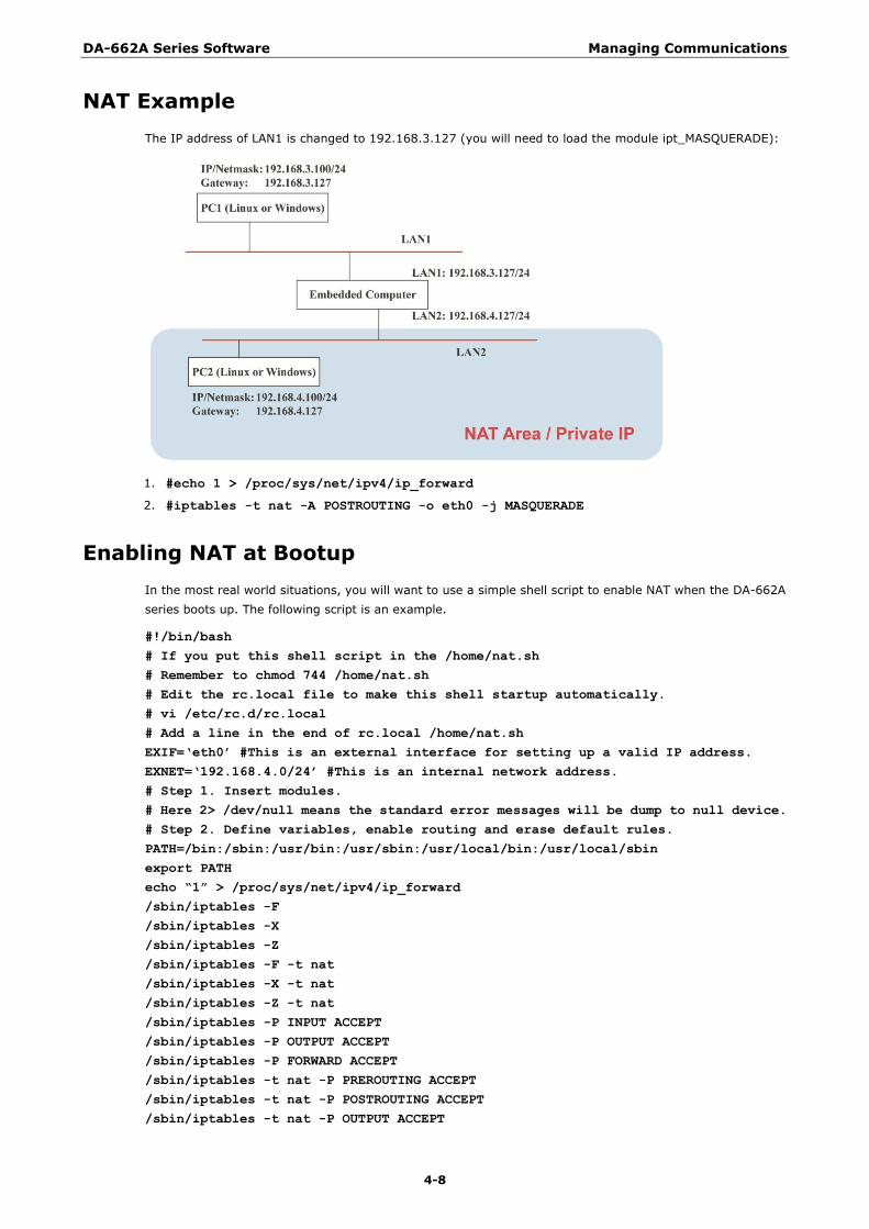
NAT Example
The IP address of LAN1 is changed to 192.168.3.127 (you will need to load the module ipt_MASQUERADE):
1. #echo 1 > /proc/sys/net/ipv4/ip_forward
2. #iptables -t nat -A POSTROUTING -o eth0 -j MASQUERADE
Enabling NAT at Bootup
In the most real world situations, you will want to use a simple shell script to enable NAT when the DA-662A
series boots up. The following script is an example.
#!/bin/bash
# If you put this shell script in the /home/nat.sh
# Remember to chmod 744 /home/nat.sh
# Edit the rc.local file to make this shell startup automatically.
# vi /etc/rc.d/rc.local
# Add a line in the end of rc.local /home/nat.sh
EXIF=„eth0‟ #This is an external interface for setting up a valid IP address.
EXNET=„192.168.4.0/24‟ #This is an internal network address.
# Step 1. Insert modules.
# Here 2> /dev/null means the standard error messages will be dump to null device.
# Step 2. Define variables, enable routing and erase default rules.
PATH=/bin:/sbin:/usr/bin:/usr/sbin:/usr/local/bin:/usr/local/sbin
export PATH
echo “1” > /proc/sys/net/ipv4/ip_forward
/sbin/iptables -F
/sbin/iptables -X
/sbin/iptables -Z
/sbin/iptables -F -t nat
/sbin/iptables -X -t nat
/sbin/iptables -Z -t nat
/sbin/iptables -P INPUT ACCEPT
/sbin/iptables -P OUTPUT ACCEPT
/sbin/iptables -P FORWARD ACCEPT
/sbin/iptables -t nat -P PREROUTING ACCEPT
/sbin/iptables -t nat -P POSTROUTING ACCEPT
/sbin/iptables -t nat -P OUTPUT ACCEPT
DA-662A Series Software Managing Communications
4-9
Dial-up Service—PPP PPP (Point to Point Protocol) is used to run IP (Internet Protocol) and other network protocols over a serial link.
PPP can be used for direct serial connections (using a null-modem cable) over a Telnet link, and links
established using a modem over a telephone line.
Modem / PPP access is almost identical to connecting directly to a network through the DA-662A series‘
Ethernet port. Since PPP is a peer-to-peer system, the DA-662A series can also use PPP to link two networks (or
a local network to the Internet) to create a Wide Area Network (WAN).
NOTE Click on the following links for more information about ppp:
http://tldp.org/HOWTO/PPP-HOWTO/index.html
http://axion.physics.ubc.ca/ppp-linux.html
The pppd daemon is used to connect to a PPP server from a Linux system. For detailed information about pppd
see the man page.
Example 1: Connecting to a PPP server over a simple dial-up
connection
The following command is used to connect to a PPP server by modem. Use this command for old ppp servers
that prompt for a login name (replace username with the correct name) and password (replace password with
the correct password). Note that debug and defaultroute 192.1.1.17 are optional.
#pppd connect „chat -v “ “ ATDT5551212 CONNECT“ “ ogin: username word: password‟
/dev/ttyM0 115200 debug crtscts modem defaultroute
If the PPP server does not prompt for the username and password, the command should be entered as follows.
Replace username with the correct username and replace password with the correct password.
#pppd connect „chat -v “ “ ATDT5551212 CONNECT“ “„user username password password
/dev/ttyM0 115200 crtscts modem
The pppd options are described below:
connect „chat etc...‟
This option gives the command to contact the PPP server. The ‗chat‘ program is used to dial a remote computer.
The entire command is enclosed in single quotes because pppd expects a one-word argument for the ‗connect‘
option. The options for ‗chat‘ are given below:
-v
verbose mode; log what we do to syslog
“ “
Double quotes—don‘t wait for a prompt, but instead do ... (note that you must include a space after the second
quotation mark)
ATDT5551212
Dial the modem, and then ...
CONNECT
Wait for an answer.
“ “
Send a return (null text followed by the usual return)
ogin: username word: password
Log in with username and password.
DA-662A Series Software Managing Communications
4-10
Refer to the chat man page, chat.8, for more information about the chat utility.
/dev/
Specify the callout serial port.
115200
The baudrate.
debug
Log status in syslog.
crtscts
Use hardware flow control between computer and modem (at 115200 this is a must).
modem
Indicates that this is a modem device; pppd will hang up the phone before and after making the call.
defaultroute
Once the PPP link is established, make it the default route; if you have a PPP link to the Internet, this is probably
what you want.
192.1.1.17
This is a degenerate case of a general option of the form x.x.x.x:y.y.y.y. Here x.x.x.x is the local IP address and
y.y.y.y is the IP address of the remote end of the PPP connection. If this option is not specified, or if just one
side is specified, then x.x.x.x defaults to the IP address associated with the local machine‘s hostname (located
in /etc/hosts), and y.y.y.y is determined by the remote machine.
Example 2: Connecting to a PPP server over a hard-wired link
If a username and password are not required, use the following command (note that noipdefault is optional):
#pppd connect „chat –v“ “ “ “ „ noipdefault /dev/ttyM0 19200 crtscts
If a username and password is required, use the following command (note that noipdefault is optional, and root
is both the username and password):
#pppd connect „chat –v“ “ “ “ „ user root password root noipdefault
/dev/ttyM0 19200 crtscts
How to check the connection
Once you‘ve set up a PPP connection, there are some steps you can take to test the connection. First, type:
/sbin/ifconfig
(The folder ifconfig may be located elsewhere, depending on your distribution.) You should be able to see all
the network interfaces that are UP. ppp0 should be one of them, and you should recognize the first IP address
as your own, and the ―P-t-P address‖ (or point-to-point address) the address of your server. Here‘s what it
looks like on one machine:
lo Link encap Local Loopback
inet addr 127.0.0.1 Bcast 127.255.255.255
UP LOOPBACK RUNNING MTU 2000
RX packets 0 errors 0 dropped 0 overrun 0
Mask 255.0.0.0
Metric 1
ppp0 Link encap Point-to-Point Protocol
inet addr 192.76.32.3 P-t-P 129.67.1.165
UP POINTOPOINT RUNNING MTU 1500
RX packets 33 errors 0 dropped 0 overrun 0
TX packets 42 errors 0 dropped 0 overrun 0
Mask 255.255.255.0
Metric 1
DA-662A Series Software Managing Communications
4-11
Now, type:
ping z.z.z.z
where z.z.z.z is the address of your name server. This should work. Here‘s what the response could look like:
waddington:~$p ping 129.67.1.165
PING 129.67.1.165 (129.67.1.165): 56 data bytes
64 bytes from 129.67.1.165: icmp_seq=0 ttl=225 time=268 ms
64 bytes from 129.67.1.165: icmp_seq=1 ttl=225 time=247 ms
64 bytes from 129.67.1.165: icmp_seq=2 ttl=225 time=266 ms
^C
--- 129.67.1.165 ping statistics ---
3 packets transmitted, 3 packets received, 0% packet loss
round-trip min/avg/max = 247/260/268 ms
waddington:~$
Try typing:
netstat –nr
This should show three routes, similar to the following:
Kernel routing table
Destination iface Gateway Genmask Flags Metric Ref Use
129.67.1.165 ppp0 0.0.0.0 255.255.255.255 UH 0 0 6
127.0.0.0 0.0.0.0 255.0.0.0 U 0 0 0 lo
0.0.0.0 ppp0 129.67.1.165 0.0.0.0 UG 0 0 6298
If your output looks similar but doesn‘t have the destination 0.0.0.0 line (which refers to the default route used
for connections), you may have run pppd without the ‗defaultroute‘ option. At this point you can try using
Telnet, ftp, or finger, bearing in mind that you‘ll have to use numeric IP addresses unless you‘ve set up
/etc/resolv.conf correctly.
Setting up a Machine for Incoming PPP Connections
This first example applies to using a modem, and requiring authorization with a username and password.
pppd /dev/ttyM0 115200 crtscts modem 192.168.16.1:192.168.16.2 login auth
You should also add the following line to the file /etc/ppp/pap-secrets:
* * “” *
The first star (*) lets everyone log in. The second star (*) lets every host connect. The pair of double quotation
marks (―‖) is to use the file /etc/passwd to check the password. The last star (*) is to let any IP connect.
The following example does not check the username and password:
pppd /dev/ttyM0 115200 crtscts modem 192.168.16.1:192.168.16.2
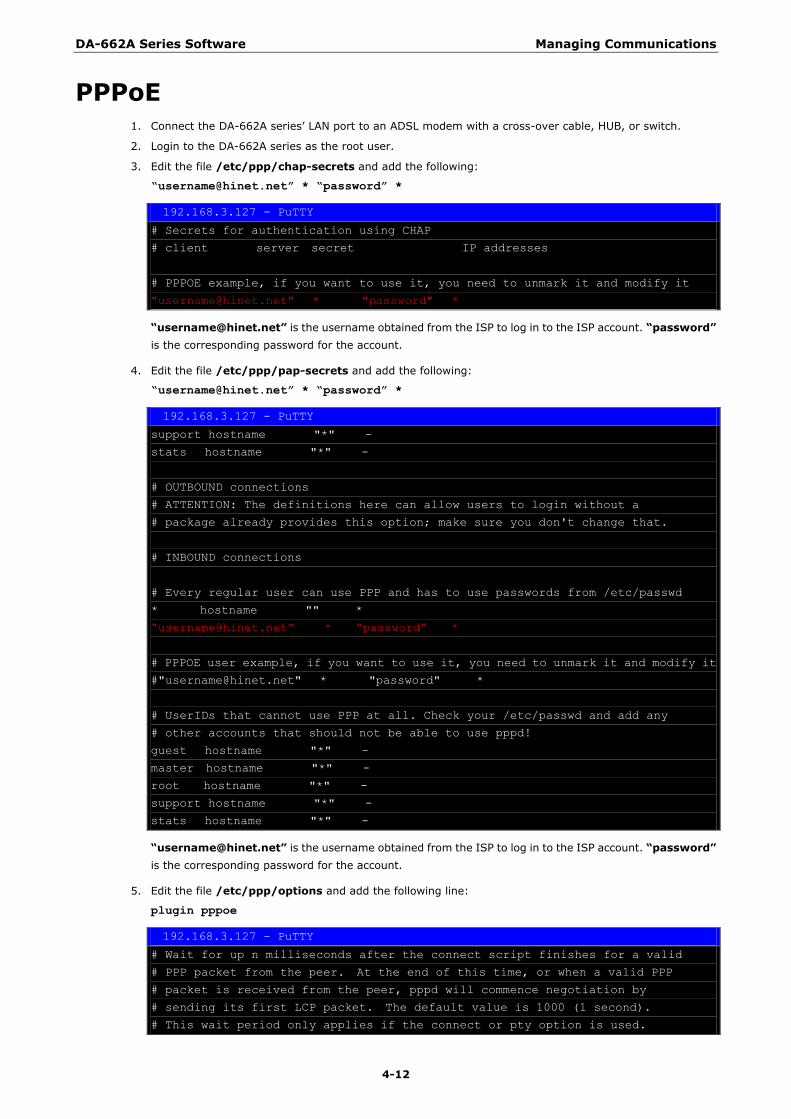
DA-662A Series Software Managing Communications
4-12
PPPoE 1. Connect the DA-662A series‘ LAN port to an ADSL modem with a cross-over cable, HUB, or switch.
2. Login to the DA-662A series as the root user.
3. Edit the file /etc/ppp/chap-secrets and add the following:
“[email protected]” * “password” *
192.168.3.127 - PuTTY
# Secrets for authentication using CHAP
# client server secret IP addresses
# PPPOE example, if you want to use it, you need to unmark it and modify it
"[email protected]" * "password" *
“[email protected]” is the username obtained from the ISP to log in to the ISP account. “password”
is the corresponding password for the account.
4. Edit the file /etc/ppp/pap-secrets and add the following:
“[email protected]” * “password” *
192.168.3.127 - PuTTY
support hostname "*" -
stats hostname "*" -
# OUTBOUND connections
# ATTENTION: The definitions here can allow users to login without a
# package already provides this option; make sure you don't change that.
# INBOUND connections
# Every regular user can use PPP and has to use passwords from /etc/passwd
* hostname "" *
―[email protected]‖ * ―password‖ *
# PPPOE user example, if you want to use it, you need to unmark it and modify it
#"[email protected]" * "password" *
# UserIDs that cannot use PPP at all. Check your /etc/passwd and add any
# other accounts that should not be able to use pppd!
guest hostname "*" -
master hostname "*" -
root hostname "*" -
support hostname "*" -
stats hostname "*" -
“[email protected]” is the username obtained from the ISP to log in to the ISP account. “password”
is the corresponding password for the account.
5. Edit the file /etc/ppp/options and add the following line:
plugin pppoe
192.168.3.127 - PuTTY
# Wait for up n milliseconds after the connect script finishes for a valid
# PPP packet from the peer. At the end of this time, or when a valid PPP
# packet is received from the peer, pppd will commence negotiation by
# sending its first LCP packet. The default value is 1000 (1 second).
# This wait period only applies if the connect or pty option is used.
DA-662A Series Software Managing Communications
4-13
#connect-delay <n>
# Load the pppoe plugin
plugin pppoe.so
# ---<End of File>---
6. Add one of two files: /etc/ppp/options.eth0 or /etc/ppp/options.eth1. The choice depends on which
LAN is connected to the ADSL modem. If you use LAN1 to connect to the ADSL modem, then add
/etc/ppp/options.eth0. If you use LAN2 to connect to the ADSL modem, then add
/etc/ppp/options.eth1. The file context is shown below:
192.168.3.127 - PuTTY
name [email protected]
mtu 1492
mru 1492
defaultroute
noipdefault
Type your username (the one you set in the /etc/ppp/pap-secrets and /etc/ppp/chap-secrets files)
after the ―name‖ option. You may add other options as desired.
7. Set up DNS
If you are using DNS servers supplied by your ISP, edit the file
/etc/resolv.conf by adding the following lines of code:
nameserver ip_addr_of_first_dns_server
nameserver ip_addr_of_second_dns_server
For example:
nameserver 168.95.1.1
nameserver 139.175.10.20
8. Use the following command to create a pppoe connection:
pppd eth0
The eth0 is what is connected to the ADSL modem LAN port. The example above uses LAN1. To use LAN2,
type:
pppd eth1
9. Type ifconfig ppp0 to check if the connection is OK or has failed. If the connection is OK, you will see
information about the ppp0 setting for the IP address. Use ping to test the IP.
10. If you want to disconnect it, use the kill command to kill the pppd process.
NFS (Network File System) The Network File System (NFS) is used to mount a disk partition on a remote machine, as if it were on a local
hard drive, allowing fast, seamless sharing of files across a network. NFS allows users to develop applications
for the DA-662A series, without worrying about the amount of disk space that will be available. The DA-662A
series supports NFS protocol for both client and server.
NOTE Click on the following links for more information about NFS:
http://www.tldp.org/HOWTO/NFS-HOWTO/index.html
http://nfs.sourceforge.net/nfs-howto/ar01s03.html
http://nfs.sourceforge.net/nfs-howto/ar01s04.html
DA-662A Series Software Managing Communications
4-14
Setting up the DA-662A series as an NFS Client
The following procedure is used to mount a remote NFS Server.
1. Establish a mount point on the NFS Client site.
2. Mount the remote directory to a local directory.
Steps 1:
#mkdir –p /home/nfs/public
Step 2:
#mount –t nfs NFS_Server(IP):/directory /mount/point
Example:
#mount –t nfs 192.168.3.100:/home/public /home/nfs/public
SNMP The DA-662A series has SNMP V1 (Simple Network Management Protocol) agent software built in. It supports
RFC1317 RS-232 like groups and RFC 1213 MIB-II.
The following simple example allows you to use an SNMP browser on the host site to query the DA-662A series,
which is the SNMP agent. The DA-662A series will respond.
***** SNMP QUERY STARTED *****
1: sysDescr.0 (octet string) Linux version 2.6.38.8 (root@Victor-virtual-debian-6) (gcc version 4.4.2 (GCC) )
#400 Thu Jul 23 15:16:52 CST 2015
2: sysObjectID.0 (object identifier) .1.3.6.1.4.1.8691.12.6622
3: sysUpTime.0 (timeticks) 0 days 00h:41m:54s.47th (251447)
4: sysContact.0 (octet string) Moxa Inc., Embedded Computing Business.
5: sysName.0 (octet string) Moxa
6: sysLocation.0 (octet string) Fl.8 No.6, Alley 6, Lane 235, Pao-Chiao Rd., Shing Tien City, Taipei, Taiwan,
R.O.C.
7: system.8.0 (timeticks) 0 days 00h:00m:00s.22th (22)
8: system.9.1.2.1 (object identifier) mib-2.31
9: system.9.1.2.2 (object identifier) internet.6.3.1
10: system.9.1.2.3 (object identifier) mib-2.49
11: system.9.1.2.4 (object identifier) ip
12: system.9.1.2.5 (object identifier) mib-2.50
13: system.9.1.2.6 (object identifier) internet.6.3.16.2.2.1
14: system.9.1.2.7 (object identifier) internet.6.3.10.3.1.1
15: system.9.1.2.8 (object identifier) internet.6.3.11.3.1.1
16: system.9.1.2.9 (object identifier) internet.6.3.15.2.1.1
17: system.9.1.3.1 (octet string) The MIB module to describe generic objects for network interface sub-layers
18: system.9.1.3.2 (octet string) The MIB module for SNMPv2 entities
19: system.9.1.3.3 (octet string) The MIB module for managing TCP implementations
20: system.9.1.3.4 (octet string) The MIB module for managing IP and ICMP implementations
21: system.9.1.3.5 (octet string) The MIB module for managing UDP implementations
22: system.9.1.3.6 (octet string) View-based Access Control Model for SNMP.
23: system.9.1.3.7 (octet string) The SNMP Management Architecture MIB.
24: system.9.1.3.8 (octet string) The MIB for Message Processing and Dispatching.
25: system.9.1.3.9 (octet string) The management information definitions for the SNMP User-based Security
Model.
26: system.9.1.4.1 (timeticks) 0 days 00h:00m:00s.04th (4)
27: system.9.1.4.2 (timeticks) 0 days 00h:00m:00s.09th (9)
28: system.9.1.4.3 (timeticks) 0 days 00h:00m:00s.09th (9)
DA-662A Series Software Managing Communications
4-15
29: system.9.1.4.4 (timeticks) 0 days 00h:00m:00s.09th (9)
30: system.9.1.4.5 (timeticks) 0 days 00h:00m:00s.09th (9)
31: system.9.1.4.6 (timeticks) 0 days 00h:00m:00s.19th (19)
32: system.9.1.4.7 (timeticks) 0 days 00h:00m:00s.22th (22)
33: system.9.1.4.8 (timeticks) 0 days 00h:00m:00s.22th (22)
34: system.9.1.4.9 (timeticks) 0 days 00h:00m:00s.22th (22)
***** SNMP QUERY FINISHED *****
NOTE Click on the following links for more information about MIB II and RS-232 like groups:
http://www.faqs.org/rfcs/rfc1213.html
http://www.faqs.org/rfcs/rfc1317.html
The DA-662A series does NOT support SNMP trap.
5 5. Programmer's Guide
This chapter includes important information for programmers.
The following topics are covered in this chapter:
Notes on Migrating Your Application from the DA-660/662 to the DA-662A series
Big endian to Little endian
The difference between Big endian and Little endian
Be careful when developing/migrating programs
Useful APIs for converting Big endian and Little endian
Conversion Example
Steps for Migrating to the DA-662A
Linux Tool Chain Introduction
Device API
RTC (Real-time Clock)
Buzzer
WDT (Watchdog Timer)
UART
LCM
KeyPad
Make File Example
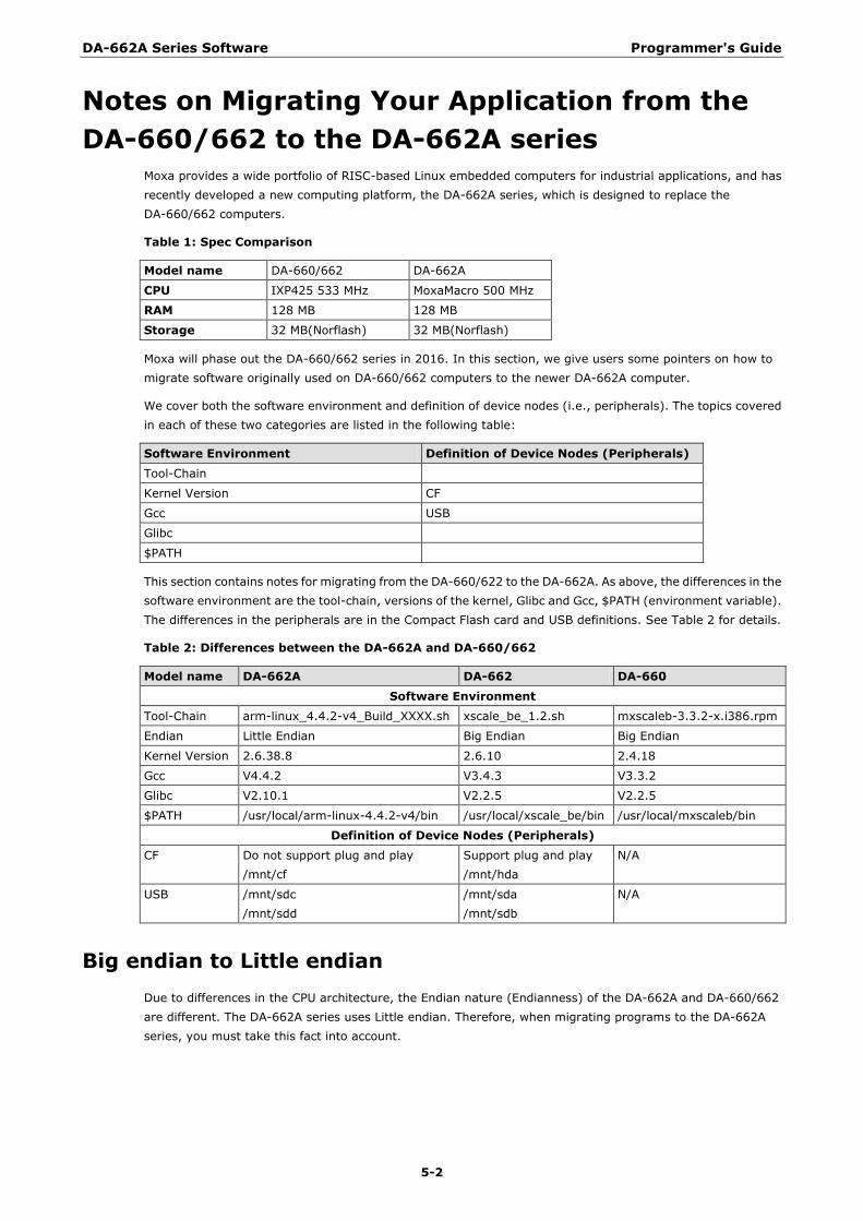
DA-662A Series Software Programmer's Guide
5-2
Notes on Migrating Your Application from the
DA-660/662 to the DA-662A series Moxa provides a wide portfolio of RISC-based Linux embedded computers for industrial applications, and has
recently developed a new computing platform, the DA-662A series, which is designed to replace the
DA-660/662 computers.
Table 1: Spec Comparison
Model name DA-660/662 DA-662A
CPU IXP425 533 MHz MoxaMacro 500 MHz
RAM 128 MB 128 MB
Storage 32 MB(Norflash) 32 MB(Norflash)
Moxa will phase out the DA-660/662 series in 2016. In this section, we give users some pointers on how to
migrate software originally used on DA-660/662 computers to the newer DA-662A computer.
We cover both the software environment and definition of device nodes (i.e., peripherals). The topics covered
in each of these two categories are listed in the following table:
Software Environment Definition of Device Nodes (Peripherals)
Tool-Chain
Kernel Version CF
Gcc USB
Glibc
$PATH
This section contains notes for migrating from the DA-660/622 to the DA-662A. As above, the differences in the
software environment are the tool-chain, versions of the kernel, Glibc and Gcc, $PATH (environment variable).
The differences in the peripherals are in the Compact Flash card and USB definitions. See Table 2 for details.
Table 2: Differences between the DA-662A and DA-660/662
Model name DA-662A DA-662 DA-660
Software Environment
Tool-Chain arm-linux_4.4.2-v4_Build_XXXX.sh xscale_be_1.2.sh mxscaleb-3.3.2-x.i386.rpm
Endian Little Endian Big Endian Big Endian
Kernel Version 2.6.38.8 2.6.10 2.4.18
Gcc V4.4.2 V3.4.3 V3.3.2
Glibc V2.10.1 V2.2.5 V2.2.5
$PATH /usr/local/arm-linux-4.4.2-v4/bin /usr/local/xscale_be/bin /usr/local/mxscaleb/bin
Definition of Device Nodes (Peripherals)
CF Do not support plug and play
/mnt/cf
Support plug and play
/mnt/hda
N/A
USB /mnt/sdc
/mnt/sdd
/mnt/sda
/mnt/sdb
N/A
Big endian to Little endian
Due to differences in the CPU architecture, the Endian nature (Endianness) of the DA-662A and DA-660/662
are different. The DA-662A series uses Little endian. Therefore, when migrating programs to the DA-662A
series, you must take this fact into account.
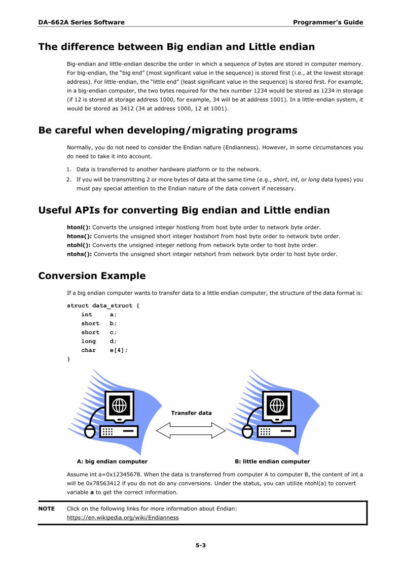
DA-662A Series Software Programmer's Guide
5-3
The difference between Big endian and Little endian
Big-endian and little-endian describe the order in which a sequence of bytes are stored in computer memory.
For big-endian, the ―big end‖ (most significant value in the sequence) is stored first (i.e., at the lowest storage
address). For little-endian, the ―little end‖ (least significant value in the sequence) is stored first. For example,
in a big-endian computer, the two bytes required for the hex number 1234 would be stored as 1234 in storage
(if 12 is stored at storage address 1000, for example, 34 will be at address 1001). In a little-endian system, it
would be stored as 3412 (34 at address 1000, 12 at 1001).
Be careful when developing/migrating programs
Normally, you do not need to consider the Endian nature (Endianness). However, in some circumstances you
do need to take it into account.
1. Data is transferred to another hardware platform or to the network.
2. If you will be transmitting 2 or more bytes of data at the same time (e.g., short, int, or long data types) you
must pay special attention to the Endian nature of the data convert if necessary.
Useful APIs for converting Big endian and Little endian
htonl(): Converts the unsigned integer hostlong from host byte order to network byte order.
htons(): Converts the unsigned short integer hostshort from host byte order to network byte order.
ntohl(): Converts the unsigned integer netlong from network byte order to host byte order.
ntohs(): Converts the unsigned short integer netshort from network byte order to host byte order.
Conversion Example
If a big endian computer wants to transfer data to a little endian computer, the structure of the data format is:
struct data_struct {
int a;
short b;
short c;
long d;
char e[4];
}
A: big endian computer B: little endian computer
Assume int a=0x12345678. When the data is transferred from computer A to computer B, the content of int a
will be 0x78563412 if you do not do any conversions. Under the status, you can utilize ntohl(a) to convert
variable a to get the correct information.
NOTE Click on the following links for more information about Endian:
https://en.wikipedia.org/wiki/Endianness
Transfer data
DA-662A Series Software Programmer's Guide
5-4
Steps for Migrating to the DA-662A
Take the following steps to migrate a program written for the DA-660/662 to the DA-662A:
1. Set up the DA-662A‘s development environment, including installing the DA-662A‘s tool chain and set the
cross compiler and glibc environment variables.
2. Develop the code (taking into consideration the Endian issue) and compile it.
3. If there are any error messages during compilation, return to Step 2.
4. Download the program to the DA-662A series via FTP.
5. Debug the program.
If bugs are found, return to Step 4.
If no bugs are found, continue with Step 7.
6. Distribute the program to additional DA-662A series units if needed.
Linux Tool Chain Introduction To ensure that an application will be able to run correctly when installed on the DA-662A series, you must
ensure that it is compiled and linked to the same libraries that will be present on the DA-662A series. This is
particularly true when the RISC processor architecture of the DA-662A series differs from the CISC x86
processor architecture of the host system, but it is also true if the processor architecture is the same.
The host tool chain that comes with the DA-662A series contains a suite of cross compilers and other tools, as
well as the libraries and headers that are necessary to compile applications for the DA-662A series. The host
environment must be running Linux to install the DA-662A series GNU Tool Chain. We have confirmed that the
following Linux distributions can be used to install the tool chain:
Redhat 7.3/8.0/9.0, Fedora core 1/2/3/4/5.
The Tool Chain will need about 1 GB of hard disk space on your PC. The DA-662A series Tool Chain is located
on the DA-662A series CD. To install the Tool Chain, insert the CD into your PC and then issue the following
commands:
#mount /dev/cdrom /mnt/cdrom
#sh /mnt/cdrom/Toolchain/linux/arm-linux_x.x.x-Vx_Build_YYMMDDHH.sh
Wait for a few minutes while the Tool Chain is installed automatically on your Linux PC. Once the host
environment has been installed, add the directory /usr/local/arm-linux-4.4.2-v4/bin/ to your path and
the directory /usr/local/arm-linux-4.4.2-v4/man/ to your manual path. You can do this temporarily for
the current login session by issuing the following commands:
#export PATH=“/usr/local/arm-linux-4.4.2-v4/bin:$PATH”
#export MANPATH=“/usr/local/arm-linux-4.4.2-v4/man:$MANPATH”
Alternatively, you can add the same commands to $HOME/.bash_profile to cause it to take effect for all login
sessions initiated by this user.
Obtaining help
Use the Linux man utility to obtain help on many of the utilities provided by the tool chain. For example to get
help on the arm-none-linux-gnueabi-gcc compiler, issue the command:
#man arm-none-linux-gnueabi-gcc
DA-662A Series Software Programmer's Guide
5-5
Cross Compiling Applications and Libraries
To compile a simple C application, just use the cross compiler instead of the regular compiler:
#arm-none-linux-gnueabi-gcc –o example –Wall –g –O2 example.c
#arm-none-linux-gnueabi-strip –s example
#arm-none-linux-gnueabi-gcc -ggdb –o example-debug example.c
Tools Available in the Host Environment
Most of the cross compiler tools are the same as their native compiler counterparts, but with an additional
prefix that specifies the target system. In the case of x86 environments, the prefix is i386-linux- and in the case
of DA-662A series boards, it is arm-none-linux-gnueabi-.
For example, the native C compiler is gcc and the cross C compiler for Moxa Marco in DA-662A series is
arm-none-linux-gnueabi-gcc.
The following cross compiler tools are provided:
ar Manage archives (static libraries)
as Assembler
c++, g++ C++ compiler
cpp C preprocessor
gcc C compiler
gdb Debugger
ld Linker
nm Lists symbols from object files
objcopy Copies and translates object files
objdump Displays information about object files
ranlib Generates indexes to archives (static libraries)
readelf Displays information about ELF files
size Lists object file section sizes
strings Prints strings of printable characters from files (usually object files)
strip Removes symbols and sections from object files (usually debugging information)
Device API The DA-662A series supports control devices with the ioctl system API. You will need to use include
<moxadevice.h>, and use the following ioctl function.
int ioctl(int d, int request,…);
Input: int d - open device node return file handle
int request – argument in or out
Use the desktop Linux‘s man page for detailed documentation:
#man ioctl
DA-662A Series Software Programmer's Guide
5-6
RTC (Real-time Clock) The device node is located at /dev/rtc. DA-662A series supports Linux standard simple RTC control. You must
include <linux/rtc.h>.
1. Function: RTC_RD_TIME
int ioctl(fd, RTC_RD_TIME, struct rtc_time *time);
Description: read time information from RTC. It will return the value on argument 3.
2. Function: RTC_SET_TIME
int ioctl(fd, RTC_SET_TIME, struct rtc_time *time);
Description: set RTC time. Argument 3 will be passed to RTC.
Buzzer The DA-662A series supports buzzer control running at a fixed frequency of 100 Hz. The buzzer‘s on/off
behavior is controlled by software. You may write a shell script to control it. The following sample shell script
is provided for reference.
Example:
#! /bin/sh
cd /sys/class/gpio
echo 10 > export
cd /sys/class/gpio/gpio10
echo out > direction
# echo 1 > value means to turn on the buzzer
echo 1 > value
# echo 0 > value means to turn off the buzzer
echo 0 > value
WDT (Watchdog Timer) 1. Introduction
The WDT works like a watchdog function. You can enable it or disable it. When the user enables WDT but the
application does not acknowledge it, the system will reboot. You can set the ack time from a minimum of 50
msec to a maximum of 60 seconds.
2. How the WDT works
The sWatchDog is enabled when the system boots up. The kernel will auto ack it. The user application can
also enable ack. When the user does not ack, it will let the system reboot.
Kernel boot
.....
....
User application running and enable user ack
....
....
DA-662A Series Software Programmer's Guide
5-7
3. The user API
The user application must include <moxadevice.h>, and link moxalib.a. A makefile example is shown
below:
all:
arm-none-linux-gnueabi-gcc –o xxxx xxxx.c -lmoxalib
int swtd_open(void)
Description
Open the file handle to control the sWatchDog. If you want to do something you must first do this.
And keep the file handle to do other.
Input
None
Output
The return value is a file handle. If there is an error, a negative value (< 0) will be returned.
You can get error from errno().
int swtd_enable(int fd, unsigned long time)
Description
Enable sWatchDog application. You must do an ack after this process.
Input
int fd - the file handle, from the swtd_open() return value.
unsigned long time - The time you wish to ack sWatchDog periodically. You must ack the
sWatchDog before timeout. If you do not ack, the system will reboot automatically. The minimal
time is 50 msec, the maximum time is 60 seconds. The time unit is msec.
Output
If OK, zero will be returned. Nonzero values indicate an error. Get the error code from errno().
int swtd_disable(int fd)
Description
Disable the application to ack sWatchDog. The kernel will perform ack automatically. You do not
need to ack the sWatchdog.
Input
int fd - the file handle from swtd_open() return value.
Output
If OK, zero will be returned. Nonzero values indicate an error. Get the error code from errno().
int swtd_get(int fd, int *mode, unsigned long *time)
Description
Get current setting values.
mode –
1 for user application enable sWatchDog: need to do ack.
0 for user application disable sWatchdog: does not need to do ack.
time – The time period to ack sWatchDog.
Input
int fd - the file handle from swtd_open() return value.
int *mode - the function will return the status of enable or disable sWatchDog.
unsigned long *time - the function will return the current time period.
Output
If OK, zero will be returned. Nonzero values indicate an error. Get the error code from errno().
DA-662A Series Software Programmer's Guide
5-8
int swtd_ack(int fd)
Description
Acknowledge sWatchDog. When the user application enables WatchDog. It needs to call this function
periodically using the user predefined time in the application program.
Input
int fd - the file handle from swtd_open() return value.
Output
If OK, zero will be returned. Nonzero values indicate an error. Get the error code from errno().
int swtd_close(int fd)
Description
Close the file handle.
Input
int fd - the file handle from swtd_open() return value.
Output
If OK, zero will be returned. Nonzero values indicate an error. Get the error code from errno().
4. Special Note
When you ―kill the application with -9‖ or ―kill without option‖ or ―Ctrl+c‖ the kernel will change to auto ack
the sWatchDog.
When your application enables the sWatchDog and does not ack, your application may have a logical error,
or your application has made a core dump. The kernel will not change to auto ack. This can cause a serious
problem, causing your system to reboot again and again.
5. User application example
Example 1:
#include <stdio.h>
#include <stdlib.h>
#include <string.h>
#include <moxadevice.h>
int main(int argc, char *argv[])
{
int fd;
fd = swtd_open();
if ( fd < 0 ) {
printf(“Open sWatchDog device fail !\n”);
exit(1);
}
swtd_enable(fd, 5000); // enable it and set it 5 seconds
while ( 1 ) {
// do user application want to do
…..
….
swtd_ack(fd);
…..
….
}
swtd_close(fd);
exit(0);
}
The makefile is shown below:
DA-662A Series Software Programmer's Guide
5-9
all:
arm-none-linux-gnueabi-gcc –o xxxx xxxx.c –lmoxalib
Example 2:
#include <stdio.h>
#include <stdlib.h>
#include <signal.h>
#include <string.h>
#include <sys/stat.h>
#include <sys/ioctl.h>
#include <sys/select.h>
#include <sys/time.h>
#include <moxadevice.h>
static void mydelay(unsigned long msec)
{
struct timeval time;
time.tv_sec = msec / 1000;
time.tv_usec = (msec % 1000) * 1000;
select(1, NULL, NULL, NULL, &time);
}
static int swtdfd;
static int stopflag=0;
static void stop_swatchdog()
{
stopflag = 1;
}
static void do_swatchdog(void)
{
swtd_enable(swtdfd, 500);
while ( stopflag == 0 ) {
mydelay(250);
swtd_ack(swtdfd);
}
swtd_disable(swtdfd);
}
int main(int argc, char *argv[])
{
pid_t sonpid;
signal(SIGUSR1, stop_swatchdog);
swtdfd = swtd_open();
if ( swtdfd < 0 ) {
printf(“Open sWatchDog device fail !\n”);
exit(1);
}
if ( (sonpid=fork()) == 0 )
do_swatchdog();
// do user application main function
…..
…..
…..
// end user application
kill(sonpid, SIGUSR1);
DA-662A Series Software Programmer's Guide
5-10
swtd_close(swtdfd);
exit(1);
}
The makefile is shown below:
all:
arm-none-linux-gnueabi-gcc –o xxxx xxxx.c –lmoxalib
UART The normal tty device node is located at /dev/ttyM0 … ttyM15, and the modem tty device node is located at
/dev/cum0 … cum15.
The DA-662A series supports Linux standard termios control. The Moxa UART Device API allows you to
configure ttyM0 to ttyM7 as RS-232, RS-422, 4-wire RS-485, or 2-wire RS-485. The DA-662A series supports
RS-232, RS-422, 2-wire RS-485, and 4-wire RS485.
You must use include <moxadevice.h>.
#define RS232_MODE 0
#define RS485_2WIRE_MODE 1
#define RS422_MODE 2
#define RS485_4WIRE_MODE 3
1. Function: MOXA_SET_OP_MODE
int ioctl(fd, MOXA_SET_OP_MODE, &mode)
Description
Set the interface mode. Argument 3 mode will pass to the UART device driver and change it.
2. Function: MOXA_GET_OP_MODE
int ioctl(fd, MOXA_GET_OP_MODE, &mode)
Description
Get the interface mode. Argument 3 mode will return the interface mode.
There are two Moxa private ioctl commands for setting up special baudrates.
Function: MOXA_SET_SPECIAL_BAUD_RATE
Function: MOXA_GET_SPECIAL_BAUD_RATE
If you use this ioctl to set a special baudrate, the termios cflag will be B4000000, in which case the B4000000
define will be different. If the baudrate you get from termios (or from calling tcgetattr()) is B4000000, you
must call ioctl with MOXA_GET_SPECIAL_BAUD_RATE to get the actual baudrate.
Example for setting the baudrate
#include <moxadevice.h>
#include <termios.h>
struct termios term;
int fd, speed;
fd = open(“/dev/ttyM0”, O_RDWR);
tcgetattr(fd, &term);
term.c_cflag &= ~(CBAUD | CBAUDEX);
term.c_cflag |= B4000000;
tcsetattr(fd, TCSANOW, &term);
speed = 500000;
ioctl(fd, MOXA_SET_SPECIAL_BAUD_RATE, &speed);
DA-662A Series Software Programmer's Guide
5-11
Example for getting the baudrate
#include <moxadevice.h>
#include <termios.h>
struct termios term;
int fd, speed;
fd = open(“/dev/ttyM0”, O_RDWR);
tcgetattr(fd, &term);
if ( (term.c_cflag & (CBAUD|CBAUDEX)) != B4000000 ) {
// follow the standard termios baudrate define
} else {
ioctl(fd, MOXA_GET_SPECIAL_BAUD_RATE, &speed);
}
Baudrate inaccuracy
Divisor = 921600/Target Baudrate. (Only Integer part)
ENUM = 8 * (921600/Target - Divisor) ( Round up or down)
Inaccuracy = ( (Target Baud Rate – 921600/(Divisor + (ENUM/8))) / Target Baud Rate )* 100%
E.g.,
To calculate 500000 bps
Divisor = 1, ENUM = 7,
Inaccuracy = 1.7%
*The Inaccuracy should less than 2% for work reliably.
Special Note
1. If the target baudrate is not a special baudrate (e.g. 50, 75, 110, 134, 150, 200, 300, 600, 1200, 1800,
2400, 4800, 9600, 19200, 38400, 57600, 115200, 230400, 460800, 921600), the termios cflag will be set
to the same flag.
2. If you use stty to get the serial information, you will get speed equal to 0.
LCM The DA-662A series only supports text mode display, with screen size of 16 cols by 2 rows. The device node is
/dev/lcm. See the examples given below. We provide a private struct defined as follows:
typedef struct lcm_xy {
int x; // col value, the arrange is 0 – 15
int y; // raw value, the arrange is 0 – 1
} lcm_xy_t;
Examples
int ioctl(fd, IOCTL_LCM_GOTO_XY, lcm_xy_t *pos);
Move the cursor position to x(col),y(raw) position. The argument 3 is the new position value.
int ioctl(fd, IOCTL_LCM_CLS, NULL);
Clears the LCM display.
int ioctl(fd, IOCTL_LCM_CLEAN_LINE, NULL);
To change one line to all spaces in the current row, and move the cursor to the 0 column of this row.
int ioctl(fd, IOCTL_LCM_GET_XY, lcm_xy_t *pos);
Get the current cursor position. The value will be returned in argument 3.
DA-662A Series Software Programmer's Guide
5-12
int ioctl(fd, IOCTL_LCM_BACK_LIGH_ON, NULL);
Turns the LCM backlight on.
int ioctl(fd, IOCTL_LCM_BACK_LIGHT_OFF, NULL);
Turns the LCM backlight off.
KeyPad The device node is /dev/keypad. The key value is defined in moxadevice.h.
int ioctl(fd, IOCTL_KEYPAD_HAS_PRESS, int *flag);
Checks how many keys have been pressed. Argument 3 returns the number of pressed keys. 0 means no keys
were pressed.
int ioctl(fd, IOCTL_KEYPAD_GET_KEY, int *key);
Gets the value of the last key that was pressed. This functions only reads one key value for each function call.
The value of the key value is returned in argument 3.
Special Note
1. The DA-662A series‘ kernel will store the ―pressed key history‖ in a buffer. The maximum buffer size is 31
keys. If the buffer overflows, the first key of the 31 that was pressed will be dropped, without sounding the
buzzer.
2. Currently, the DA-662A series does NOT support pressing more than 1 key at the same time.
Product S/N
The DA-662A series stores the product serial number in the system. You can use the following method to get
Product S/N and utilize the number to develop security functions such as program protection and program
initialization identification. The following example shows how to retrieve the product S/N.
Example:
root@Moxa:~# cat /proc/driver/serid
TABC0123456789
Make File Example The following Makefile file sample code is provided for reference.
CC = arm-none-linux-gnueabi-gcc
CPP = arm-none-linux-gnueabi-gcc
SOURCES = hello.c
OBJS = $(SOURCES:.c=.o)
all: hello
hello: $(OBJS)
$(CC) -o $@ $^ $(LDFLAGS) $(LIBS)
clean:
rm -f $(OBJS) hello core *.gdb
A A. System Commands
Linux normal command utility collection
File Manager
1. cp copy file
2. ls list file
3. ln make symbolic link file
4. mount mount and check file system
5. rm delete file
6. chmod change file owner & group & user
7. chown change file owner
8. chgrp change file group
9. sync sync file system, let system file buffer be saved to hardware
10. mv move file
11. pwd display now file directly
12. df list now file system space
13. mkdir make new directory
14. rmdir delete directory
Editor
1. vi text editor
2. cat dump file context
3. zcat compress or expand files
4. grep search string on file
5. cut get string on file
6. find find file where are there
7. more dump file by one page
8. test test file exist or not
9. sleep sleep (seconds)
10. echo echo string
DA-662A Series Software System Commands
A-2
Network
1. ping ping to test network
2. route routing table manager
3. netstat display network status
4. ifconfig set network ip address
5. tracerout trace route
6. tftp
7. telnet
8. ftp
Process
1. kill kill process
2. ps display now running process
Other
1. dmesg dump kernel log message
2. sty to set serial port
3. zcat dump .gz file context
4. mknod make device node
5. free display system memory usage
6. date print or set the system date and time
7. env run a program in a modified environment
8. clear clear the terminal screen
9. reboot reboot / power off/on the server
10. halt halt the server
11. du estimate file space usage
12. gzip, gunzip compress or expand files
13. hostname show system’s host name
Moxa Special Utilities
1. kversion show kernel version
2. upramdisk mount ramdisk
3. downramdisk unmount ramdisk
B B. Using the Push Buttons to Operate the LCD
Screen
The DA-662A series embedded computers implement a set of LCD functions to provide users with on-site
parameter readings of the current state of the computer. The LCD screen is operated using the four push
buttons. The parameters include the model name, firmware version, network settings, in addition to other
parameters. We use the DA-662A series as an example to demonstrate the steps to obtain these parameters.
A typical example:
• Model Name and Firmware Version—Screen that appears when the system boots up.
Press MENU to enter the main menu.
• Main Menu
Press ﹀ or use SEL to select an item.
Press ﹀ or use SEL to select an item.
Press ︿ or use SEL to select an item.
LCD Screen
Displays the process values
and parameters
Up Key
Browse sub-menus
upward
Down Key
Browse sub-menus
downward
Select Key
Enter sub-menu
Menu Key
Back to the previous
menu
^ ﹀ MENU SEL
DA-662A
DA-662A SERIES
Ver 1.0
Network
Serial Port
Serial Port
Console Port
Console Port
Return
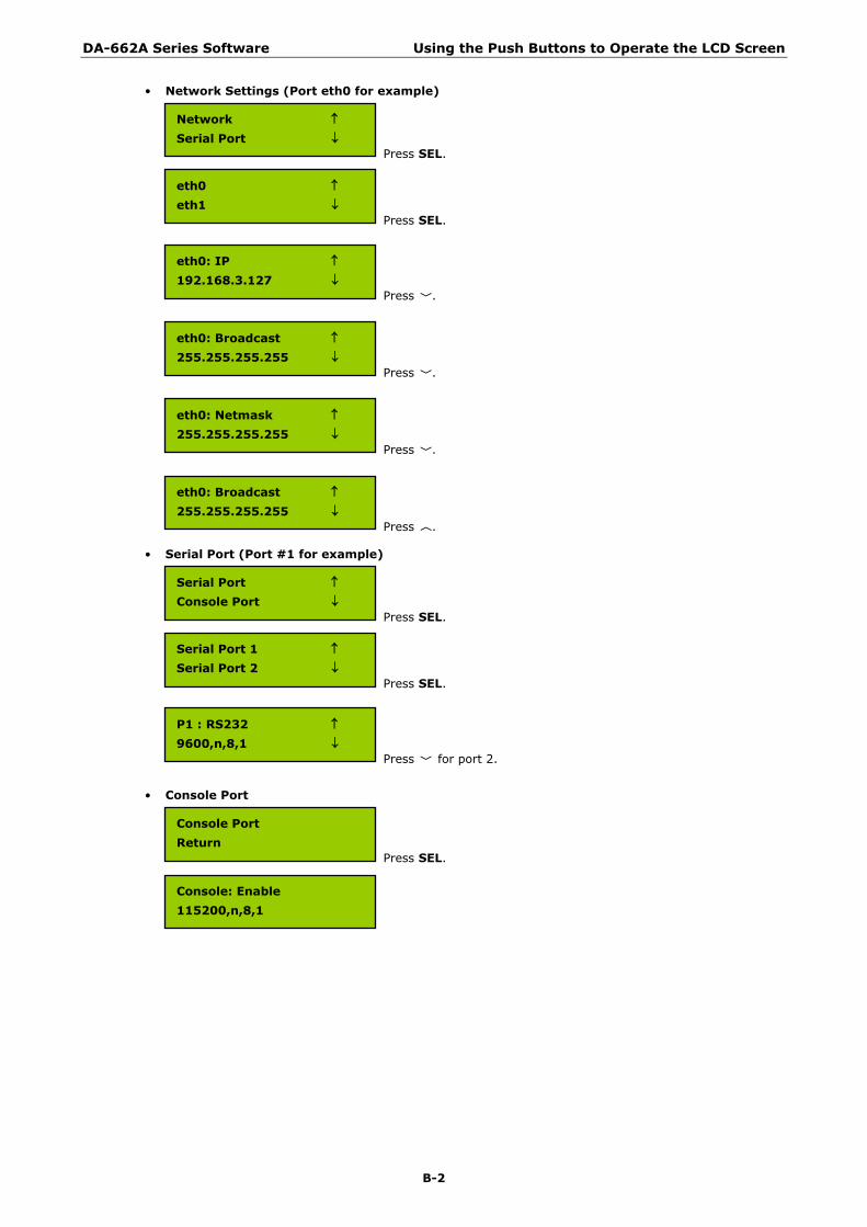
DA-662A Series Software Using the Push Buttons to Operate the LCD Screen
B-2
• Network Settings (Port eth0 for example)
Press SEL.
Press SEL.
Press ﹀.
Press ﹀.
Press ﹀.
Press ︿.
• Serial Port (Port #1 for example)
Press SEL.
Press SEL.
Press ﹀ for port 2.
• Console Port
Press SEL.
Network
Serial Port
eth0
eth1
eth0: IP
192.168.3.127
eth0: Broadcast
255.255.255.255
eth0: Netmask
255.255.255.255
eth0: Broadcast
255.255.255.255
Serial Port
Console Port
Serial Port 1
Serial Port 2
P1 : RS232
9600,n,8,1
Console Port
Return
Console: Enable
115200,n,8,1