Embed Size (px)
Citation preview
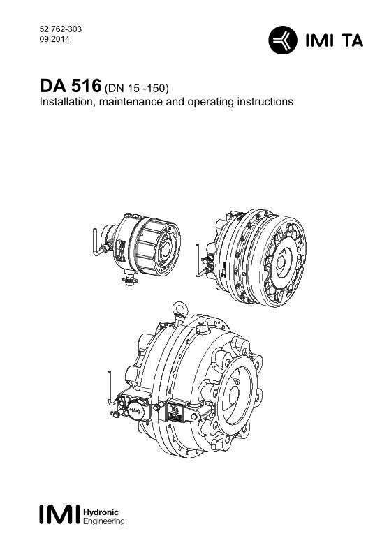
52 762-303 09.2014
DA 516 (DN 15 -150)Installation, maintenance and operating instructions
2
General
• High-performing and compact, these differential pressure controllers for heating and cooling systems are particularly effective in situations requiring high temperatures and/or pressure drops.
• They are also suitable for use on the primary and secondary side in district heating and cooling systems.
• Rust protection is assured due to the electrophoretically painted ductile iron body (KTL).
Marking
The valve displays the following data:
• TAH - Manufacturer: according to table 3
• Material: according to table 2
• DN: according to table 2
• Max. (PN) working pressure according to table 2
• CE-marking according to table 1; 3
• → Unidirectional flow arrow for the recommended direction of flow
• Max. permitted temperature: 120°C (table 3)
• Setting range: 5-30, 10-60, 10-100, 60-150, 100-400 kPa (table 3)
• Date of manufacture: year, week (table 3)
Installation
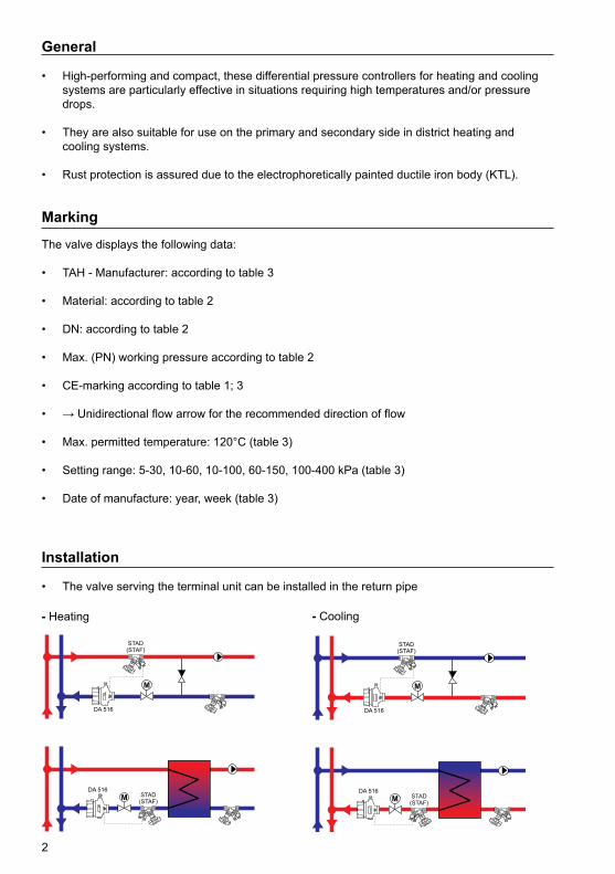
• The valve serving the terminal unit can be installed in the return pipe
- Heating - Cooling
3
• The valve may be installed in a vertical, horizontal or inclined pipeline.
• The valve should be installed to match the direction of flow, with the flow direction arrow shown on the valve body or on the identification plate.
• Install the valve so that venting is possible and the ∆p pressure adjustment pilot is visible and accessible.
• Check allowed positions of the presetting nut / pilot and provide adequate space for future service and maintenance.
• Installation of a strainer upstream of the valve is strongly recommended.
Installation - Preparation
• Ensure valve is suitable for service conditions e.g. pressure, temperature, service media.
• Ensure the pipe system has been cleaned.
• Ensure the strainer is installed.
• Ensure all sealing surfaces are clean and undamaged.
• The installation shall provide adequate means of draining and venting to avoid harmful effects such as water hammer, vacuum collapse, corrosion and uncontrolled chemical reactions and to permit cleaning, inspection and maintenance in the correct manner.
• The valve has been designed for load, appropriate to its intended use and other reasonable foreseeable operating conditions. Load caused by traffic, wind and earthquake, have not been taken into account.
Flange Joints
Flanges may be damaged by over tightening the bolts. The following procedures will reduce this risk:
• Check that the counter-flanges are parallel before the valve is installed.
• Lubricate the threads on the bolts and fit washers. Ensure adequate lubrication of bolts and washers.
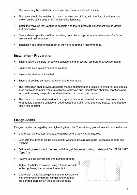
• Full faced gaskets should be used with integral flanges according to standard EN 1092-2:1997 (Type 21).
• Always use the correct size and number of bolts. • Tighten the bolts crosswise using a torque wrench to the tightening torque set out in table 4.
• Check that the full faced gaskets are in accordance with the given standard for flanges and that they are centred correctly on the sealing surfaces.
4
Threaded Joints
• The valves are supplied with the external inch threads ends.
• To avoid distortion of the valve during installation, the valve must be held with the proper tools so that the valve is in line.
• Care should be taken to avoid ‘pipe ending’. This is a condition that occurs when the pipe is screwed in too far resulting in distortion to the valve seat.
• The male thread on the pipe must have fully formed undamaged threads.
Start-up procedure
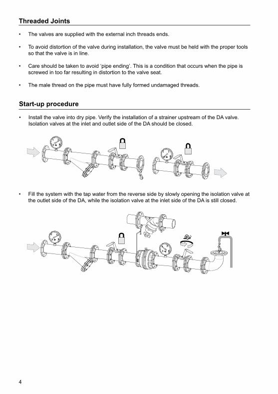
• Install the valve into dry pipe. Verify the installation of a strainer upstream of the DA valve. Isolation valves at the inlet and outlet side of the DA should be closed.
• Fill the system with the tap water from the reverse side by slowly opening the isolation valve at the outlet side of the DA, while the isolation valve at the inlet side of the DA is still closed.
5
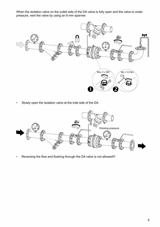
When the isolation valve on the outlet side of the DA valve is fully open and the valve is under pressure, vent the valve by using an 8 mm spanner.
• Slowly open the isolation valve at the inlet side of the DA.
• Reversing the flow and flushing through the DA valve is not allowed!!!
6
Pre-commission
• Check that the arrow on the valve body is in the same direction as the flow.
• Check that the strainer basket is clean.
• Slowly fill the system with the tap water according to the «Start-up procedure»
• Close the bypasses.
• Check sealing.
Commission
• Slowly raise the pressure to working pressure.
• Vent the valve.
• Check sealing.
• Set the ∆p according to the table supplied with the valve or from table 5.
7
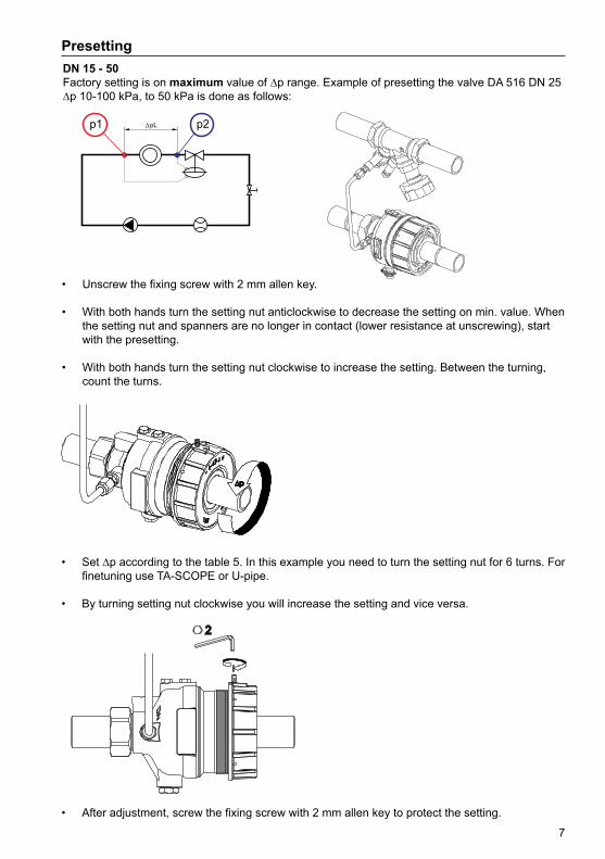
PresettingDN 15 - 50Factory setting is on maximum value of ∆p range. Example of presetting the valve DA 516 DN 25 ∆p 10-100 kPa, to 50 kPa is done as follows:
• Unscrew the fixing screw with 2 mm allen key.
• With both hands turn the setting nut anticlockwise to decrease the setting on min. value. When the setting nut and spanners are no longer in contact (lower resistance at unscrewing), start with the presetting.
• With both hands turn the setting nut clockwise to increase the setting. Between the turning, count the turns.
• Set ∆p according to the table 5. In this example you need to turn the setting nut for 6 turns. For finetuning use TA-SCOPE or U-pipe.
• By turning setting nut clockwise you will increase the setting and vice versa.
• After adjustment, screw the fixing screw with 2 mm allen key to protect the setting.
8
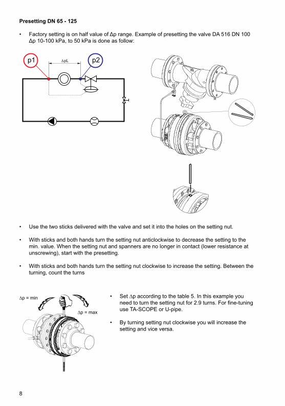
Presetting DN 65 - 125
• Factory setting is on half value of Δp range. Example of presetting the valve DA 516 DN 100 Δp 10-100 kPa, to 50 kPa is done as follow:
• Set ∆p according to the table 5. In this example you need to turn the setting nut for 2.9 turns. For fine-tuning use TA-SCOPE or U-pipe.
• By turning setting nut clockwise you will increase the setting and vice versa.
• Use the two sticks delivered with the valve and set it into the holes on the setting nut.
• With sticks and both hands turn the setting nut anticlockwise to decrease the setting to the min. value. When the setting nut and spanners are no longer in contact (lower resistance at unscrewing), start with the presetting.
• With sticks and both hands turn the setting nut clockwise to increase the setting. Between the turning, count the turns
9
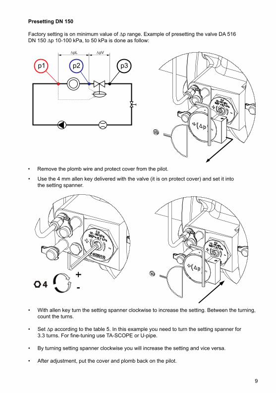
Presetting DN 150
Factory setting is on minimum value of ∆p range. Example of presetting the valve DA 516DN 150 ∆p 10-100 kPa, to 50 kPa is done as follow:
• Remove the plomb wire and protect cover from the pilot.
• Use the 4 mm allen key delivered with the valve (it is on protect cover) and set it into the setting spanner.
• With allen key turn the setting spanner clockwise to increase the setting. Between the turning, count the turns.
• Set ∆p according to the table 5. In this example you need to turn the setting spanner for 3.3 turns. For fine-tuning use TA-SCOPE or U-pipe.
• By turning setting spanner clockwise you will increase the setting and vice versa.
• After adjustment, put the cover and plomb back on the pilot.
10
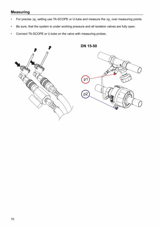
Measuring
• For precise ∆pL setting use TA-SCOPE or U-tube and measure the ∆pL over measuring points.
• Be sure, that the system is under working pressure and all isolation valves are fully open.
• Connect TA-SCOPE or U-tube on the valve with measuring probes.
DN 15-50
11
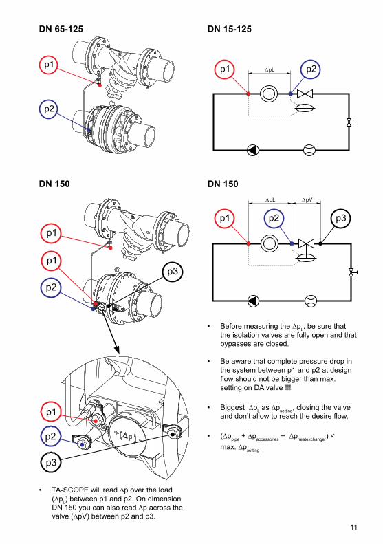
DN 65-125
DN 150
• TA-SCOPE will read ∆p over the load (∆pL) between p1 and p2. On dimension DN 150 you can also read ∆p across the valve (∆pV) between p2 and p3.
DN 15-125
DN 150
• Before measuring the ∆pL, be sure that the isolation valves are fully open and that bypasses are closed.
• Be aware that complete pressure drop in the system between p1 and p2 at design flow should not be bigger than max. setting on DA valve !!!
• Biggest ∆pL as ∆psetting, closing the valve and don’t allow to reach the desire flow.
• (∆ppipe + ∆paccessories + ∆pheatexchanger) < max. ∆psetting
12
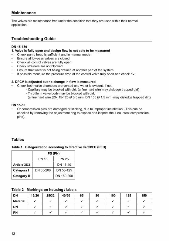
Troubleshooting Guide
DN 15-1501. Valve is fully open and design flow is not able to be measured• Check pump head is sufficient and in manual mode• Ensure all by-pass valves are closed• Check all control valves are fully open• Check strainers are not blocked • Ensure that water is not being drained at another part of the system. • If possible measure the pressure drop of the control valve fully open and check Kv.
2. DPCV is adjusted but no change in flow is measured• Check both valve chambers are vented and water is evident, if not; - Capillary may be blocked with dirt. (a fine hard wire may dislodge trapped dirt) - Throttle in valve body may be blocked with dirt. (a fine hard wire (DN 15-125 Ø 0,5 mm; DN 150 Ø 1,5 mm) may dislodge trapped dirt) DN 15-50• Or compression pins are damaged or sticking, due to improper installation. (This can be checked by removing the adjustment ring to expose and inspect the 4 no. steel compression pins).
Maintenance
The valves are maintenance free under the condition that they are used within their normal application.
Tables
Table 1 Categorization according to directive 97/23/EC (PED)
Table 2 Markings on housing / labelsDN 15/20 25/32 40/50 65 80 100 125 150
Material
DN
PN
PS (PN)PN 16 PN 25
Article 3&3 DN 15-40
Category I DN 65-200 DN 50-125
Category II DN 150-200
13
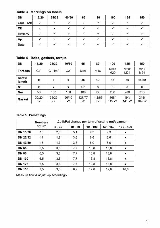
Table 3 Markings on labelsDN 15/20 25/32 40/50 65 80 100 125 150Logo - TAH
CE x x
Temp. oC
Δp
Date
Table 4 Bolts, gaskets, torqueDN 15/20 25/32 40/50 65 80 100 125 150
Threads G1” G1 1/4” G2” M16 M16 M16/M20
M20/M24
M20/M24
Screw length x x x 35 40 45 50 45/50
No x x x 4/8 8 8 8 8
Nm 50 100 150 100 130 200 280 310
Gasket 30/23x2
39/25x2
56/40x2
127/77x2
142/89x2
168/115 x2
194/141 x2
218/169 x2
Table 5 Presettings
Measure flow & adjust ∆p accordingly
Numbersof turn
Δp [kPa] change per turn of setting nut/spanner5 - 30 10 - 60 10 - 100 60 - 150 100 - 400
DN 15/20 10 2,6 5,1 9,3 9,3 xDN 25/32 14 1,8 3,6 6,6 6,6 xDN 40/50 15 1,7 3,3 6,0 6,0 xDN 65 6,5 3,8 7,7 13,8 13,8 xDN 80 6,5 3,8 7,7 13,8 13,8 xDN 100 6,5 3,8 7,7 13,8 13,8 xDN 125 6,5 3,8 7,7 13,8 13,8 xDN 150 7,5 3,3 6,7 12,0 12,0 40,0

14
Notes:
15
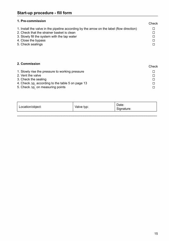
Start-up procedure - fill form
1. Pre-commission
1. Install the valve in the pipeline according by the arrow on the label (flow direction)2. Check that the strainer basket is clean3. Slowly fill the system with the tap water4. Close the bypass5. Check sealings
2. Commission
1. Slowly rise the pressure to working pressure2. Vent the valve3. Check the sealing4. Check ∆pL according to the table 5 on page 135. Check ∆pL on measuring points
Location/object: Valve typ: Date:Signature:
----------------------------------------------------------------------------------------------------------------------------------
Check
Check

www.imi-hydronic.com
We reserve the right to introduce technical alterations without previous notice.