Embed Size (px)
Citation preview

FP7-287800 SALUS
SALUS-FP7-287800• D7.1.1 • Version 1.0, dated January 30, 2013
SALUS “Scalable, Standard based Interoperability Framework for
Sustainable Proactive Post Market Safety Studies”
SPECIFIC TARGETED RESEARCH PROJECT
PRIORITY Objective ICT-2011.5.3b) Tools and environments enabling the re-use of
electronic health records
SALUS D7.1.1 Functional and Non-functional Evaluation Criteria
for SALUS Components
Due Date: January 31, 2013
Actual Submission Date: January 31, 2013
Project Dates: Project Start Date : February 01, 2012
Project End Date : January 31, 2015
Project Duration : 36 months
Deliverable Leader: SRDC
Project co-funded by the European Commission within the Seventh Framework Programme (2007-2013)
Dissemination Level
PU Public X
PP Restricted to other programme participants (including the Commission Services)
RE Restricted to a group specified by the consortium (including the Commission Services)
CO Confidential, only for members of the consortium (including the Commission Services)

FP7-287800 SALUS
SALUS-FP7-287800• D7.1.1 • Version 1.0, dated January 30, 2013
Document History:
Version Date Changes From Review
V0.1 November 16,
2012
Initial Document SRDC All Partners
V0.2 November 30,
2012
Draft review SRDC SRDC
V0.3 December 10,
2012
AGFA, OFFIS, INSERM,SRDC,
EUROREC Input
AGFA, OFFIS,
INSERM, SRDC
All Partners
V0.4 December 21,
2012
AGFA, OFFIS, SRDC updates AGFA, OFFIS,
SRDC
All Partners
V0.1 January 30, 2013 SRDC Final updates SRDC All Partners
Contributors (Benef.) Gokce Banu Laleci Erturkmen (SRDC), Mustafa Yuksel (SRDC), Anil Sinaci
(SRDC), Gunnar Declerck (INSERM)
Kristof Depraetere (AGFA)
Tobias Krahn, Frerk Mueller (OFFIS)
Jos Devlies (EUROREC)
Andrea Migliavacca (LISPA)
Responsible Author Gokce Banu Laleci
Erturkmen Email [email protected]
Beneficiary SRDC Phone +90 3122101763

FP7-287800 SALUS
SALUS-FP7-287800• D7.1.1 • Version 1.0, dated January 30, 2013
SALUS Consortium Contacts:
Beneficiary Name Phone Fax E-Mail
SRDC Gokce Banu Laleci
Erturkmen
+90-312-2101763 +90(312)2101837 [email protected]
EUROREC Georges De Moor +32-9-2101161 +32-9-3313350 [email protected]
UMC Niklas Norén +4618656060 +46 18 65 60 80 [email protected]
OFFIS Wilfried Thoben
+49-441-9722131
+49-441-9722111
AGFA Dirk Colaert +32-3-4448408 +32 3 444 8401 [email protected]
ERS Gerard Freriks +31 620347088 +31 847371789 [email protected]
LISPA Alberto Daprà +390239331605 +39 02 39331207 [email protected]
INSERM Marie-Christine Jaulent +33142346983 +33153109201 marie-
TUD Peter Schwarz +49 351 458 2715 +49 351 458 7319 Peter.Schwarz@uniklinikum-
dresden.de
ROCHE Jamie Robinson +41-61-687 9433 +41 61 68 88412 [email protected]

FP7-287800 SALUS
SALUS-FP7-287800• D7.1.1 • Version 1.0, dated January 30, 2013
EXECUTIVE SUMMARY
The SALUS evaluation and testing framework will follow the standard process defined on the evaluation
reference model and guide ISO/IEC CD 25040[1] of the SQuaRE series of standards. This standard details
the activities and tasks providing their purposes, outcomes and complementary information that can be used
to guide a software product quality evaluation. The outcomes of applying a standard process approach for the
evaluation activities in SALUS will be the repeatability, reproducibility, impartiality and objectivity of the
full process.
This documents after presenting the principal standard steps of the SALUS evaluation strategy (prepare,
establish, specify, design, execute, report) will describe in detail the procedures used to generate the
evaluation criteria that will be applied for the assessment of functional and non-functional characteristics
(functionality, reliability, usability, efficiency, maintainability and portability) of SALUS components. These
procedures will be reported in Section 5 and used as guide to perform the SALUS evaluation activities that
will be reported in the next deliverables.
The project identified the following techniques that will be applied for evaluation of the SALUS components
and architecture: functional tests; unit tests; fault tolerance analysis; user interface analysis; execution time
measurements; inspection of documentation and analysis of the software installation procedures.
These techniques and their evaluation criteria, as defined by the SALUS evaluation team, are presented in
Section 5, modularized as recommended in ISO/IEC 25041 former ISO/IEC 14598-6[2] ISO/IEC 14598-6[2]
and ISO/IEC 9126, in order to have a structured set of instructions and data used for the evaluation. It
specifies the evaluation methods applicable to evaluate a quality characteristic (functional/non functional)
and it identifies the evidence it needs. It also defines the elementary evaluation procedure and the format for
reporting the measurements resulting from the application of the technique.

FP7-287800 SALUS
SALUS-FP7-287800• D7.1.1 • Version 1.0, dated January 30, 2013
TABLE OF CONTENTS
Executive Summary ....................................................................................................................................... - 4 - Table of contents ........................................................................................................................................... - 5 - 1 PURPOSE ............................................................................................................................................. - 8 - 2 REFERENCE DOCUMENTS .............................................................................................................. - 8 -
2.1 Definitions and Acronyms ............................................................................................................. - 9 - 3 The SALUS Evaluation Strategy ........................................................................................................ - 11 -
3.1 Steps of the Software product quality evaluation reference model (ISO/IEC 25040) ................. - 12 - 4 SALUS Evaluation Procedure ............................................................................................................ - 14 -
4.1 Evaluation Preparation ................................................................................................................ - 14 - 4.2 Evaluation Requirements ............................................................................................................. - 15 - 4.3 Specification of the Evaluation .................................................................................................... - 15 - 4.4 Design the Evaluation .................................................................................................................. - 16 - 4.5 Evaluation technique ................................................................................................................... - 16 - 4.6 Evaluation modules ..................................................................................................................... - 17 -
5 Functional and Non-Functional Evaluation Criteria Modules ............................................................ - 18 - 5.1 EM1 - Functionality: Functional Test Cases ............................................................................... - 19 -
5.1.1 Introduction ......................................................................................................................... - 19 - 5.1.2 Scope ................................................................................................................................... - 19 - 5.1.3 Inputs and metrics ................................................................................................................ - 21 - 5.1.4 Interpretation of results ........................................................................................................ - 21 -
5.2 EM2 - Functionality: Unit Tests .................................................................................................. - 21 - 5.2.1 Introduction ......................................................................................................................... - 21 - 5.2.2 Scope ................................................................................................................................... - 22 - 5.2.3 Inputs and metrics ................................................................................................................ - 23 - 5.2.4 Interpretation of results ........................................................................................................ - 23 -
5.3 EM3 - Reliability: Fault tolerance analysis ................................................................................. - 23 - 5.3.1 Introduction ......................................................................................................................... - 23 - 5.3.2 Scope ................................................................................................................................... - 24 - 5.3.3 Inputs and metrics ................................................................................................................ - 24 - 5.3.4 Interpretation of results ........................................................................................................ - 25 -
5.4 EM4 - Usability: User interface Inspection ................................................................................. - 25 - 5.4.1 Introduction ......................................................................................................................... - 25 - 5.4.2 Scope ................................................................................................................................... - 25 - 5.4.3 Inputs and metrics ................................................................................................................ - 26 - 5.4.4 Interpretation of results ........................................................................................................ - 27 -
5.5 EM5 - Efficiency: Execution Time Measurement ....................................................................... - 27 - 5.5.1 Introduction ......................................................................................................................... - 27 - 5.5.2 Scope ................................................................................................................................... - 28 - 5.5.3 Inputs and metrics ................................................................................................................ - 28 - 5.5.4 Interpretation of results ........................................................................................................ - 28 -
5.6 EM6 - Maintainability: Inspection of Documents (Checklists) ................................................... - 29 - 5.6.1 Introduction ......................................................................................................................... - 29 - 5.6.2 Scope ................................................................................................................................... - 29 - 5.6.3 Inputs and metrics ................................................................................................................ - 29 - 5.6.4 Interpretation of results ........................................................................................................ - 30 -
5.7 EM7 - Portability: Analysis of the Installation ............................................................................ - 30 - 5.7.1 Introduction ......................................................................................................................... - 30 - 5.7.2 Scope ................................................................................................................................... - 30 - 5.7.3 Inputs and metrics ................................................................................................................ - 30 - 5.7.4 Interpretation of results ........................................................................................................ - 31 -
6 Conclusions ......................................................................................................................................... - 31 - 7 References ........................................................................................................................................... - 32 - APPENDIX 1. EVALUATION LEVELS ............................................................................................... - 33 -

FP7-287800 SALUS
SALUS-FP7-287800• D7.1.1 • Version 1.0, dated January 30, 2013
APPENDIX 2. TEST CASE Descriptions ............................................................................................... - 34 - 7.1 Templates .................................................................................................................................... - 34 -
7.1.1 Use Case Template .............................................................................................................. - 34 - 7.1.2 Use-Case (B)asic flows ....................................................................................................... - 34 - 7.1.3 Use-Case (A)lternative flows .............................................................................................. - 34 - 7.1.4 Fault Cases ........................................................................................................................... - 34 - 7.1.5 (S)cenarios to be tested ........................................................................................................ - 35 - 7.1.6 Execution ............................................................................................................................. - 35 -
7.2 Test Case Definitions for Common Data Element Repository .................................................... - 35 - 7.2.1 TC-4.2-1 Import a Content Model to CDE Repository ....................................................... - 35 - 7.2.2 TC-4.2-2 Annotate a Content Model with CDEs in CDE Repository ................................. - 38 - 7.2.3 TC-4.2-3 Search CDEs ........................................................................................................ - 40 - 7.2.4 TC-4.2-4 Browse/View CDEs ............................................................................................. - 42 -
7.3 Test Case Definitions for Semantic Interoperability Layer (SIL) and Semantic Resource Set ... - 44 - 7.3.1 TC-4.3-1 Export SALUS Core Ontology from CDE Repository ........................................ - 44 - 7.3.2 TC-4.3-2 Map Content Model Ontologies to SALUS Core Ontology ................................ - 46 - 7.3.3 TC-4.3-3 Include a Terminology System to the SALUS Semantic Resource Set ............... - 50 - 7.3.4 TC-4.3-4 Map a Terminology System Code to Other Terminology System Codes ............ - 52 - 7.3.5 TC-4.3-5 Include an External Domain Ontology to the Semantic Resource Set ................. - 54 - 7.3.6 TC-4.3-6 Align an External Domain Ontology with SALUS Core Ontology ..................... - 56 - 7.3.7 TC-4.4-1 Retrieve a Clinical Data Instance ......................................................................... - 58 - 7.3.8 TC-4.4-2 Convert to SALUS Semantic Data Representation .............................................. - 60 - 7.3.9 TC-4.4-3 Export SALUS Semantic Data Representation .................................................... - 62 - 7.3.10 TC-4.4-4 Export a Clinical Data Instance ........................................................................... - 64 - 7.3.11 TC-4.4-5 Query in SIL ........................................................................................................ - 67 - 7.3.12 TC-4.4-6 Query a SALUS Semantic Data Representation .................................................. - 68 - 7.3.13 TC-4.4-7 Translate Query to SALUS Semantic Data Representation ................................. - 71 - 7.3.14 TC-4.4-8 Export Query ........................................................................................................ - 72 - 7.3.15 TC-4.4-9 Subscribe to SALUS SIL ..................................................................................... - 74 - 7.3.16 TC-4.4-10 Cancel Subscription to SALUS SIL .................................................................. - 75 -
7.4 Test Case Definitions for Technical Interoperability Layer (TIL) .............................................. - 77 - 7.4.1 TC-5.1-1-1 Subscription for Clinical Data through TILDS ................................................ - 77 - 7.4.2 TC-5.1-1-2 Subscribe to Data Source through TILDSQS ................................................... - 80 - 7.4.3 TC-5.1-2-1 Retrieving clinical data through TILDS on subscription based query .............. - 82 - 7.4.4 TC-5.1-2-2 Retrieving data from data source through TILQSDS on subscription based query -
84 - 7.4.5 TC-5.1-3-1 Cancel Subscription for Clinical Data through TILDS .................................... - 86 - 7.4.6 TC-5.1-3-2 Cancel Subscription to Data Source through TIDSQS ..................................... - 88 - 7.4.7 TC-5.2-2-1 Querying data through TILDS .......................................................................... - 90 - 7.4.8 TC-5.2-2-2 Querying data source through TIDSQS ............................................................ - 92 -
7.5 Test Case Definitions for ICSR Reporting Tool (IRT) ............................................................... - 95 - 7.5.1 TC-5.3-1 Reporting an ADE Using ICSR Reporting Tool .................................................. - 95 - 7.5.2 TC-5.3-2 Recording an ADE Notified by the ADE Notification Tool to be Reported Later- 98
- 7.5.3 TC-5.3-3 Accessing Previously Sent and Waiting to be Reported ICSRs .......................... - 99 - 7.5.4 TC-5.3-4 Updating and Sending an ICSR Reported in a Previous Session....................... - 101 - 7.5.5 TC-5.3-5 Finalizing and Sending a to be Reported Later ICSR ........................................ - 102 -
7.6 Test Case Definitions for ADE Notification Tool (ANT) ......................................................... - 103 - 7.6.1 TC-6.1-1 ADE Detection ................................................................................................... - 103 - 7.6.2 TC-6.1-2 Semi-automatic ADE Detection ........................................................................ - 106 - 7.6.3 TC-6.1-3 Manual ADE Detection...................................................................................... - 108 - 7.6.4 TC-6.1-4 Change ADE Detection Rule ............................................................................. - 110 - 7.6.5 TC-6.1-5 Add ADE Detection Rule .................................................................................. - 113 - 7.6.6 TC-6.1-6 Delete ADE Detection Rule ............................................................................... - 115 - 7.6.7 TC-6.1-7 ADE detection rule management ....................................................................... - 118 - 7.6.8 TC-6.1-8 ADE detection rule validation ........................................................................... - 120 -

FP7-287800 SALUS
SALUS-FP7-287800• D7.1.1 • Version 1.0, dated January 30, 2013
7.7 Test Case Definitions for Security and Privacy Toolset ............................................................ - 121 - 7.7.1 TC-5.4-1 De-identify Clinical Data Instance ..................................................................... - 121 - 7.7.2 TC-5.4-2 Pseudonymize Clinical Data .............................................................................. - 123 - 7.7.3 TC-5.4-3 Re-identify a Pseudonym ................................................................................... - 124 - 7.7.4 TC-5.4-4 Audit Logging .................................................................................................... - 126 -
7.8 Safety Analysis Tools ................................................................................................................ - 128 - 7.8.1 TC-6.2-1 Query Population Data for Safety Analysis ....................................................... - 128 - 7.8.2 TC-6.2-2 Query Population Data for Case Series Characterization .................................. - 131 - 7.8.3 TC-6.2-3 Query Population Data for Temporal Pattern Characterization ......................... - 132 - 7.8.4 TC-6.2-4 Visualizing Patient History ................................................................................ - 132 - 7.8.5 TC-6.2-5 Subscribe to Population Data for Signal Detection ........................................... - 134 -
APPENDIX 3. REQUIREMENTS TRACEABILITY MATRIX .......................................................... - 138 -

FP7-287800 SALUS
SALUS-FP7-287800• D7.1.1 • Version 1.0, dated January 30, 2013
1 PURPOSE
The purpose of this Deliverable is to establish the SALUS evaluation strategy for the evaluation of SALUS
software components. The evaluation methodology in reference to selected standards is defined and
evaluation criteria that will be applied for the assessment of functional and non-functional characteristics
(functionality, reliability, usability, efficiency, maintainability and portability) of SALUS components are
clearly identified. This is the first Deliverable of Task 7.1-Functional and Non-Functional Tests and End-
User Validation of SALUS Components. After the definition of the functional and non-functional evaluation
criteria for SALUS components in this deliverable, the results of the evaluation (to be conducted in
conformance to the methods defined in this deliverable), will be reported in two phases in Deliverable 7.1.2
(Test and Evaluation Report for SALUS Components –R1) and Deliverable 7.1.3 (Test and Evaluation
Report for SALUS Components –R2).
It should be noted that, apart from the evaluation of the SALUS components to be carried out in Task 7.1, in
SALUS, the pilot application deployments will also be validated within the scope of Task 7.2 - SALUS Pilot
Application Validation. The evaluation criteria for SALUS pilot application validation will be provided
through Deliverable 7.2.1-Functional and Non-functional Evaluation Criteria for SALUS Pilot Application.
2 REFERENCE DOCUMENTS
The following documents were used or referenced in the development of this document:
ISO/IEC CD 25040: Software engineering - Software product Quality Requirements and Evaluation (SQuaRE)
- Evaluation reference model and guide, Switzerland: International Organization for Standardization.
ISO/IEC 14598-6: Software engineering -- Product evaluation -- Part 6: Documentation of evaluation modules.
Geneva, Switzerland: International Organization for Standardization.
ISO/IEC 9126-1: Software Engineering-Software product quality-Part 1 : Quality model. Geneva, Switzerland:
International Organization for Standardization.
ISO/IEC. 1999a. ISO/IEC 14598-1: Software product evaluation-Part 1 : General overview. Geneva,
Switzerland: International Organization for Standardization.
ISO/IEC CD 25010: Software engineering-Software product Quality Requirements and Evaluation (SQuaRE)
Quality model, Switzerland: International Organization for Standardization.
ISO/IEC CD 25030: Software engineering -- Software product Quality Requirements and Evaluation
(SQuaRE) -- Quality requirements, Switzerland: International Organization for Standardization.
ISO/IEC. 1999a. ISO/IEC 14598-5: Information technology -- Software product evaluation -- Part 5: Process
for evaluators. Geneva, Switzerland: International Organization for Standardization.
ISO/IEC CD 8402-1, Quality Concepts and Teminology Part One: Generic Terms and Definitions,
international Standards Organisation, December 1990.
ISO 9241 Ergonomics of Human System Interaction, Geneva, Switzerland: International Organization for
Standardization.
SALUS Deliverable 3.3.1- Requirement Specification of the SALUS Architecture

FP7-287800 SALUS
SALUS-FP7-287800• D7.1.1 • Version 1.0, dated January 30, 2013
2.1 Definitions and Acronyms
Table 1 List of Abbreviations and Acronyms
Table 2 Definitions
Term DESCRIPTION
data collection of values assigned to base measures, derived measures and/or indicators
decision criteria thresholds, targets, or patterns used to determine the need for action or further
investigation, or to describe the level of confidence in a given result
Abbreviation/
Acronym DEFINITION
A Answer
ANT ADE Notification Tool
C Component
CF Code Fragments
CL Check List
CSC Case Series Characterization
EM Evaluation Module
EMA Efficiency Metric of the Architecture
EMC Efficiency Metric
ET Execution time
F Fault
FMA Functionality Metric of the Architecture
FMC Functionality Metric
I Installations
IEC International Electrotechnical Commission
IFF ICSR form filling
IFM ICSR form management
IRT ICSR Reporting Tool
ISO International Organization for Standardization
JETM Java™ Execution Time Measurement
MMA Maintainability Metric of the Architecture
MMC Maintainability Metric
MTBF Mean Time Between Failure
N Number
OP Operating System
PH Patient History
PMA Portability Metric of the Architecture
PMC Portability Metric
RMA Reliability Metric of the Architecture
RMC Reliability Metric
SDC Standard Deviation Coefficient
SIL Semantic Interoperability Layer
TAS Temporal Association Screening
TC Test Case
TIL Technical Interoperability Layer
TPD Temporal Pattern Discovery
UMA Usability Metric of the Architecture
UMC Usability Metric
UT Unit Test

FP7-287800 SALUS
SALUS-FP7-287800• D7.1.1 • Version 1.0, dated January 30, 2013
derived measure measure that is defined as a function of two or more values of base measures
developer individual or organisation that performs development activities (including
requirements analysis, design, testing through acceptance) during the software life
cycle process
end user individual person who ultimately benefits from the outcomes of the system
entity object that is to be characterised by measuring its attributes
evaluation
method
procedure describing actions to be performed by the evaluator in order to obtain
results for the specified measurement applied to the specified product components
or on the product as a whole
evaluation
module
package of evaluation technology for measuring software quality characteristics,
sub characteristics or attributes
evaluation tool an instrument that can be used during evaluation to collect data, to perform
interpretation of data or to automate part of the evaluation
evaluator individual or organisation that performs an evaluation
failure termination of the ability of a product to perform a required function or its
inability to perform within previously specified limits
fault incorrect step, process or data definition in a computer program
functional
requirement
requirement that specifies a function that a system or system component must be
able to perform
indicator measure that provides an estimate or evaluation of specified attributes derived
from a model with respect to defined information needs
measure (noun) variable to which a value is assigned as the result of measurement
measure (verb) make a measurement
measurement set of operations having the object of determining a value of a measure
process system of activities, which use resources to transform inputs into outputs
quality model defined set of characteristics, and of relationships between them, which provides a
framework for specifying quality requirements and evaluating quality
requirements expression of a perceived need that something be accomplished or realized
software product set of computer programs, procedures, and possibly associated documentation and
data
software product
evaluation
technical operation that consists of producing an assessment of one or more
characteristics of a software product according to a specified procedure
software quality capability of software product to satisfy stated and implied needs when used under
specified conditions
software quality
characteristic
category of software quality attributes that bears on software quality
software quality
evaluation
systematic examination of the extent to which a software product is capable of
satisfying stated and implied needs
system a combination of interacting elements organised to achieve one or more stated
purposes
user individual or organisation that uses the system to perform a specific function
value number or category assigned to an attribute of an entity by making a measurement
verification confirmation, through the provision of objective evidence, that specified
requirements have been fulfilled

FP7-287800 SALUS
SALUS-FP7-287800• D7.1.1 • Version 1.0, dated January 30, 2013
3 THE SALUS EVALUATION STRATEGY
The essential parts of software quality evaluation are the quality model, the method of evaluation, software
measurement, and the supporting tools. To develop good software, quality requirements are specified, the
software quality assurance process are planned, implemented and controlled, and both intermediate products
and end products are evaluated.
SALUS evaluation activities will use the Software Product Quality Evaluation Reference Model as a
reference, which describes the process, activities and tasks performed during the quality evaluation of a
software product. This reference models is defined by the standard ISO/IEC 25040 that contains general
requirements for specification and evaluation of software quality and clarifies the general concepts providing
a process description for evaluating quality of software product stating the requirements for the application
of the evaluation process. This specification is part of the SQuaRE series of standards created by ISO (
International Organization for Standardization) and IEC (International Electrotechnical Commission).
SQuaRE replaces the current ISO/IEC 9126 series [3] and the 14598 series [4].
The reference model for software product quality evaluation will detail the activities and tasks
providing their purposes, outcomes and complementary information that can be used to guide a software
product quality evaluation. To evaluate software quality, the following steps are followed: first prepare the
evaluation, then establish the evaluation requirements, specify, design, execute and, finally, report the
evaluation (see Figure 1). Deliverable D.7.1.1 only reports the four first steps of the reference model, the
evaluation execution and report will be part of D7.1.2 and D7.1.3.
Figure 1 - Software product quality evaluation reference model ISO/IEC 25040
The principal objective of using a standard as evaluation process in the SALUS evaluation activities is to
promote the following desirable evaluation process characteristics:

FP7-287800 SALUS
SALUS-FP7-287800• D7.1.1 • Version 1.0, dated January 30, 2013
repeatability: repeated evaluation of the same component to the same evaluation specification
by the same evaluator should produce results that can be accepted as being identical,
reproducibility: evaluation of the same component to the same evaluation specification by a
different evaluator should produce results that can be accepted as being identical,
impartiality: the evaluation should not be biased towards any particular result,
objectivity: the evaluation results should be factual, i.e. not coloured by the feelings or the
opinions of the evaluator.
The purpose of the Deliverable 7.1.1 is to determine techniques and evaluation criteria to be applied to
components of SALUS. The components that will go through the process of evaluation are:
ADE Notification Tool (ANT)
ICSR Reporting Tool (IRT)
Safety Analysis Tools
Semantic Interoperability Layer (SIL) and Semantic Resource Set
Technical Interoperability Layer (TIL)
Security and Privacy Toolset
Common Data Element Repository
The evaluation requirements for each component are included in the Appendix 3 as a Requirement
Traceability Matrix.
In Deliverable 7.1.2 and 7.1.3, our objective is to apply these techniques and use the criteria listed in D7.1.1.
So test and evaluation results of SALUS components will be reported in deliverables “7.1.2: Test and
Evaluation Report for SALUS Components –R1” and “7.1.3 Test and Evaluation Report for SALUS
Components –R2”.
The next section provides an overview of the steps detailed in the reference model. These steps intend to
present the general evaluation process, the detailed procedures for the SALUS evaluation framework will be
detailed in Section 4.
3.1 Steps of the Software product quality evaluation reference model (ISO/IEC
25040)
Prepare the evaluation
The purposes of the evaluation will be to validate and verify the developed software in respect to the
collected functional and non-functional requirements and perform the further adjustments that may be
requested by end users. On top of establishing an evaluation environment for SALUS components, a testing
environment will be designed for the proper testing of the SALUS components and services.
The types of products to be evaluated are the components of the SALUS infrastructure; this
evaluation will follow a plan with the detailed evaluation activities, tools, adopted standards and criteria to
be applied (Section 5).
Establish evaluation requirements
The establishment of the evaluation requirements will be performed in three steps:

FP7-287800 SALUS
SALUS-FP7-287800• D7.1.1 • Version 1.0, dated January 30, 2013
Obtaining the software product quality requirements for the software product quality
requirements specification
Defining the extent of the evaluation based on criteria such as target date for the evaluation,
purpose of the evaluation
And finally, establishing the expected evaluation levels which define the evaluation techniques
to be applied and evaluation results to be achieved.
Quality requirements like functionality, reliability, usability, effectiveness, maintainability and
portability will be considered as defined by the ISO/IEC 25010 [5]. Functional requirements depend on the
application domain needs, quality requirements can be identified using quality model. Some quality
requirements should be transformed into functional requirements, such as back up functions for reliability
and usability support. Some other quality requirements should be reflected on design strategies, such as
program architecture and modularity.
Specify the evaluation
Software product quality evaluation requirements should be allocated for each SALUS architecture
components in such a way that it is possible to define appropriate measure and measurement method that can
be used to evaluate the specified requirements defined previously. Decision criteria shall be established for
the selected measures that can be internal for the components evaluation and external for the integrated
architecture.
Design the evaluation
Design of the evaluation will produce an evaluation plan on the basis of the evaluations specification; this
activity takes into account the components of the software product to be evaluated and the evaluation
methods proposed by the evaluator.
The goal of this activity is to combine the specified measurements or verifications with the form of the
various product components to be evaluated in order to document the detailed methods to be applied to
implement the specified measurements or verifications on these components.
Execute the evaluation
The purpose of the evaluation execution is to obtain results from performing actions to measure and verify
the software product according to the evaluation requirements, as specified in the evaluation specification
and as planned in the evaluation plan.
Report the evaluation
The evaluation reports will be generated after the evaluation of each component and ensuring that sufficient
information on evaluation results is provided. The evaluation reports format will comply with ISO/IEC
25041 former ISO/IEC 14598-5[7].
FP7-287800 SALUS
SALUS-FP7-287800• D7.1.1 • Version 1.0, dated January 30, 2013
4 SALUS EVALUATION PROCEDURE
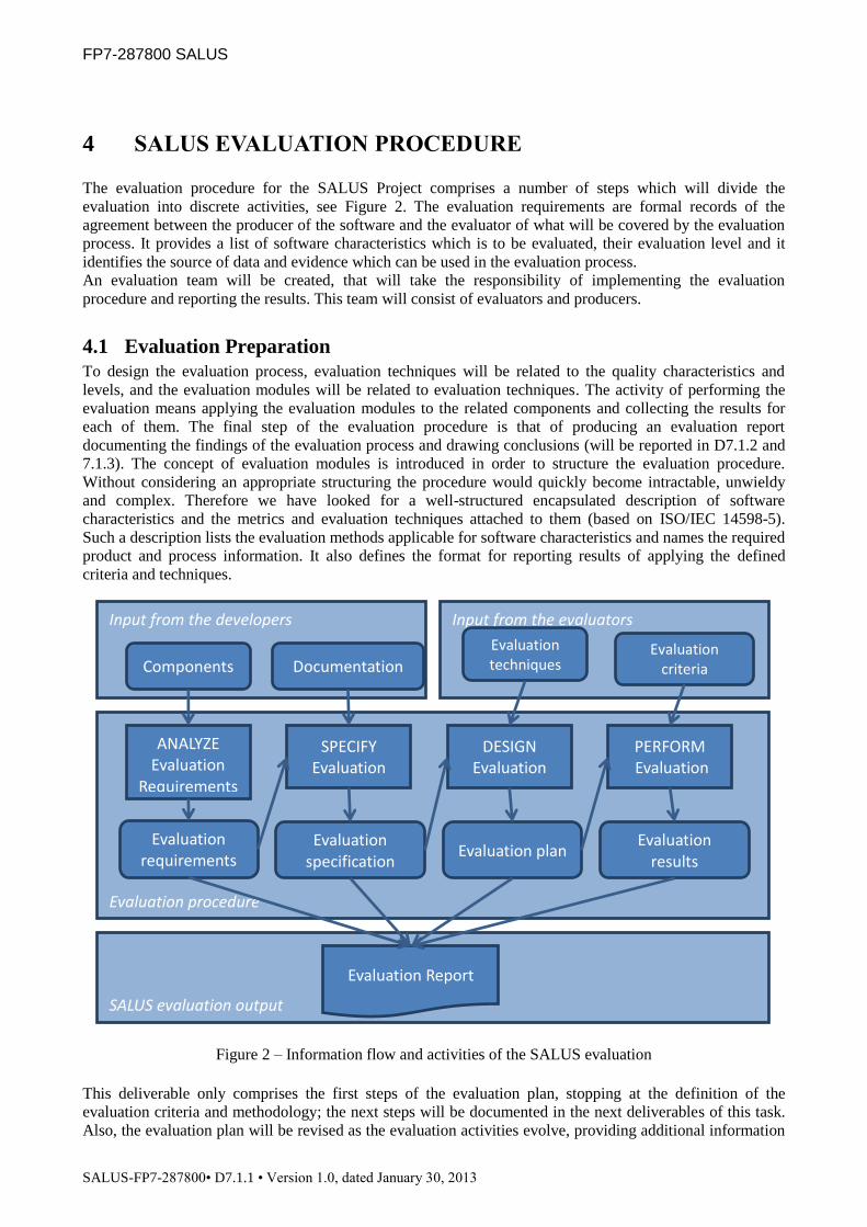
The evaluation procedure for the SALUS Project comprises a number of steps which will divide the
evaluation into discrete activities, see Figure 2. The evaluation requirements are formal records of the
agreement between the producer of the software and the evaluator of what will be covered by the evaluation
process. It provides a list of software characteristics which is to be evaluated, their evaluation level and it
identifies the source of data and evidence which can be used in the evaluation process.
An evaluation team will be created, that will take the responsibility of implementing the evaluation
procedure and reporting the results. This team will consist of evaluators and producers.
4.1 Evaluation Preparation
To design the evaluation process, evaluation techniques will be related to the quality characteristics and
levels, and the evaluation modules will be related to evaluation techniques. The activity of performing the
evaluation means applying the evaluation modules to the related components and collecting the results for
each of them. The final step of the evaluation procedure is that of producing an evaluation report
documenting the findings of the evaluation process and drawing conclusions (will be reported in D7.1.2 and
7.1.3). The concept of evaluation modules is introduced in order to structure the evaluation procedure.
Without considering an appropriate structuring the procedure would quickly become intractable, unwieldy
and complex. Therefore we have looked for a well-structured encapsulated description of software
characteristics and the metrics and evaluation techniques attached to them (based on ISO/IEC 14598-5).
Such a description lists the evaluation methods applicable for software characteristics and names the required
product and process information. It also defines the format for reporting results of applying the defined
criteria and techniques.
Figure 2 – Information flow and activities of the SALUS evaluation
This deliverable only comprises the first steps of the evaluation plan, stopping at the definition of the
evaluation criteria and methodology; the next steps will be documented in the next deliverables of this task.
Also, the evaluation plan will be revised as the evaluation activities evolve, providing additional information
Input from the developers
Components Documentation
Input from the evaluators
Evaluation techniques
Evaluation criteria
Evaluation procedure
Evaluation requirements
Evaluation specification
Evaluation plan Evaluation
results
ANALYZE
Evaluation Requirements
SPECIFY
Evaluation
DESIGN
Evaluation
PERFORM
Evaluation
SALUS evaluation output
Evaluation Report

FP7-287800 SALUS
SALUS-FP7-287800• D7.1.1 • Version 1.0, dated January 30, 2013
that allows the plan to be adjusted or detailed. So the next deliverables of this task will be an update of this
document until the evaluation plan and activities are completed.
The next chapters will detail the evaluation requirements, identifying the criteria of the evaluation and
specifying the evaluation in detail.
4.2 Evaluation Requirements
The evaluator and the producer of the software must agree on which quality characteristics are to be
evaluated and to which level they are to be assured. The formal record of this agreement of what will be
covered by the evaluation is called the evaluation requirements. Quality can be defined as the totality of
characteristics of a software product that bear on its ability to satisfy stated or implied needs [8]. To make
this definition more operational we have used the characteristics defined in ISO/IEC 9126.
As it seems difficult to obtain consensus on the generic specification of quality characteristics, including
relation to sub characteristics and to measures for the case to be evaluated, evaluation requirements may
specify evaluation levels for the quality characteristics selected. Evaluation levels are related, on the one
hand, to the importance attached by the requester to a given characteristic. The chosen level should be
meaningful with regard to the assumed usage and environment of the software product (e.g. safety,
economic, security, and environment related aspects).
On the other hand, an evaluation level defines the depth or thoroughness of the evaluation in terms of
evaluation techniques to be applied and evaluation results to be achieved. As a consequence evaluation at
different levels gives different level of confidence in the quality of the software product. There are four
levels which form an increasing set of evaluation requirements, where D is the lowest level and A is the
highest level. The level can be chosen independently for each characteristic. The levels selected for the
SALUS evaluation will be based on the ISO/IEC 25040 proposed evaluation levels described in Appendix 1.
For a relevant quality characteristic, the risks and consequences involved by the non conformity of the
product to requirements relating to this characteristic, as well as benefits from high quality, should be
assessed for all the relevant aspects.
Table 3 shows the evaluation levels for the quality characteristics considering the SALUS requirements
considering the possible risks. When several aspects need to be considered, the most stringent level should
be selected.
Characteristics Safety aspects Economy aspects Security aspects Environment related
aspects
Functionality Level B Level D Level B Level D
Reliability Level D Level D Level C Level D
Usability Level D Level D Level D Level D
Efficiency Level D Level D Level D Level D
Maintainability Level D Level D Level D Level D
Portability Level D Level D Level D Level D
Table 3 – Quality Characteristics versus Evaluation Levels
4.3 Specification of the Evaluation
It is necessary to perform an analysis of the product submitted for evaluation in order to identify the various
product parts and elements of process evidence it consists of. This information, which will be called product
items, is needed in order to identify which evaluations can be performed. The results of this analysis are
used, together with the evaluation requirements, to build the evaluation specification.
The specification of the evaluation are organized according to the quality characteristics, in this case the
characteristics of ISO/IEC 9126. The evaluation specification associated with each characteristic must be
formulated as a combination of the following types of statements:

FP7-287800 SALUS
SALUS-FP7-287800• D7.1.1 • Version 1.0, dated January 30, 2013
An exact reference to statements in the software requirement specification document, the user
manual, or possibly other information, specifying program requirements that must be evaluated.
Supplementary statements about the software product which are either not mentioned in the
program specification or need to be explained more carefully for the evaluation.
An exact reference to statements in relevant standards and regulations documents where
additional program requirements are given which also are included in the evaluation
specification.
Only functional and non-functional requirements mentioned or referred to in the evaluation specification will
be evaluated. Therefore the evaluation specification must be detailed and complete. The requirements are
listed in Appendix 3 and were extracted from the deliverable D3.3.1, it is important that these requirements
are a part of this deliverable so that their status can be updated during the course of the evaluation and from
the feed back from the users and developers.
4.4 Design the Evaluation
The design of the evaluation contains attaching evaluation techniques to software characteristics and levels
as well as attaching evaluation modules to evaluation techniques. Based on this information an evaluation
process can be planned. Table 4 identifies relevant evaluation techniques. After determining the evaluation
techniques, that is, identifying which software characteristics are considered and how thoroughly, and after
identifying the technical constraints of the product (like product type, design or programming language), a
set of applicable evaluation modules will be defined and applied to evaluate the SALUS components and
architecture.
In order to elaborate an evaluation specification to satisfy some evaluation requirements, it is necessary to
specify measures. Measures are based on evaluation techniques that may be chosen according to quality
characteristics and evaluation levels. As mentioned before, when several aspects need to be considered, the
most stringent level is selected. Thus, for each quality characteristic the most stringent level of Table 3 is
assigned. In the following table for each quality characteristics, a list of evaluation techniques that will be
applied according to the evaluation levels selected is proposed. Please note that these methods are selected
based on the guidelines provided by ISO/IEC 25040 (See APPENDIX 1, Table 6).
Quality
Characteristic
Level Evaluation Techniques
Functionality B Functional Tests - component
Testing (Through Unit tests)
Reliability C Fault tolerance analysis
Usability D User Interface Inspection
Efficiency D Execution Time Measurement
Maintainability D Inspection of documents (check lists)
Portability D Analysis of installation
Table 4 – Evaluation techniques to implement in SALUS
The next chapter will be devoted for each of these techniques composing the functional and non-functional
evaluation criteria modules of the SALUS evaluation plan.
4.5 Evaluation technique
Each component’s evaluation will be executed based on the following functional evaluation modules:

FP7-287800 SALUS
SALUS-FP7-287800• D7.1.1 • Version 1.0, dated January 30, 2013
functional test cases, unit tests.
Functional Test Cases: Functional Test Cases are derived from the Use Case Specifications provided in
Requirements Specification of SALUS Project (D3.3.1). Each component's use case is divided into the
operations that take place during the execution, based on the use case activity diagram. Scenarios then are
built: each one representing a sequence of the above operations based on the test case input data. For each
scenario the expected result is determined. After performing the evaluation on each test case, the percentage
of executions the outcome matches the expected result is reported for each scenario. In Appendix 2, Test
Case Specifications for each component are provided.
Unit tests are standalone tests that verify if the components function(s) under test meet the requirements. For
SALUS unit tests will be developed and run for the code involved in each component. The percentage of
successful unit cases for each unit will be reported.
Also there will be performed tests for the non-functional evaluation modules for evaluating Reliability,
Usability, Efficiency, Maintainability and Portability through fault tolerance analysis, user interface,
execution time measurement, inspection of documentation, analysis of software installation procedures.
4.6 Evaluation modules
The evaluation modules that will be tested are the following:
EM1 - Functionality: Use Case Tests: The functionality tests will be executed through specific
use test cases. Each test case is defined from a specific use case which conducts to the definition
of a set of conditions or variables under which the tester will measure and verify whether the
relevant SALUS components are working correctly or not, i.e. the software functionalities
correspond to the proposed architecture requirements.
EM2 - Functionality: Unit Tests: These are standalone tests that verify if the components
function(s) under test meet the requirements. For the evaluation, unit tests will be implemented
by the developers along with the creation of the code. With these unit tests we can ensure that, at
least conceptually, all the different pathways of the components are exercised.
EM3 - Reliability: Fault tolerance analysis: Constructing a dependable and fault-tolerant
system is inherently difficult. Not only should the system work under normal circumstances, but
must also continue operation and provide potentially degraded service under hostile
circumstances. This evaluation module will evaluate the degree of fault tolerance of each
SALUS components, by testing the system through erroneous input cases.
EM4 - Usability: User Interface Inspection: This evaluation module has the purpose to assess
the usability of the user interface. ISO 9241[6] provides checklists for: Presentation of
information, user guidance, menu dialogues, command dialogues, direct manipulation dialogues
and form filling dialogues. These will be taken in to account while the User Interfaces are
inspected.
EM5 - Efficiency: Execution Time Measurement: The time of execution that the components
actions take can have a great impact on the user experience. So, this module evaluates if the
components perform in a way that provide the functionalities fast enough to the end-user, and
the user has the feeling to work fine with the tool without waiting time. For this, execution time
of the selected critical use cases for our end users will be measured.
EM6 - Maintainability: Inspection of Documents (Check Lists): The maintenance process is
activated when a system undergoes modifications to the code and associated documentation due
to an error, a deficiency, a problem, or the need for an improvement or adaptation. The
objective is to assess whether it is possible to modify an existing system while preserving its
integrity.
EM7 - Portability: Analysis of Installation: Portability is the degree of independence a
software product, or portion of it, has from any particular hardware and/or operating system
platform.

FP7-287800 SALUS
SALUS-FP7-287800• D7.1.1 • Version 1.0, dated January 30, 2013
5 FUNCTIONAL AND NON-FUNCTIONAL EVALUATION
CRITERIA MODULES
Functional and non-functional evaluation criteria modules provide a flexible and structured approach to
define criteria for monitoring the quality of intermediate products during the development process and for
evaluation of final products. The purpose of using evaluation modules is to ensure that software evaluations
can be repeatable, reproducible and objective.
These modules define a set structured instructions and data used for an evaluation. It specifies the criteria
applicable to evaluate a quality characteristic and it identifies the evidence of it needs. It also defines the
elementary evaluation procedure and the format for reporting the measurements resulting from the
application of the technique.
The modules described in next chapters will make clear what specific aspect of a software quality
characteristic is being measured. It specifies the criteria for making the measurement as well as the
preconditions and accuracy of the measurement. The aim is to make the various aspects (principles, metrics,
activities, etc.) of evaluation visible and to show how they are handled. They are documented as specified on
the standard ISO/IEC 14598-6:
1. It provides formal information about the evaluation module and gives an introduction to the
evaluation technique described in the evaluation module.
2. Defines the scope of applicability of the evaluation module.
3. Specifies the input products required for the evaluation and defines the data to be collected and
measures to be calculated.
4. Contains information about how to interpret measurement results.
As described in Section 4.6, the evaluation modules define the criteria for the evaluation of the SALUS
components considering the functional and non-functional quality characteristics specified on the SQuaRE
series of standards:
Functional:
• Functionality: Functional Test Cases
• Functionality: Unit Tests
Non functional:
• Reliability: Fault tolerance Analysis
• Usability: User interface inspection
• Efficiency: Execution time measurement
• Maintainability: Inspection of development documentation
• Portability: Analysis of software installation procedures
The next sections describe the evaluation techniques and criteria to apply for each functional and non
functional quality characteristics.

FP7-287800 SALUS
SALUS-FP7-287800• D7.1.1 • Version 1.0, dated January 30, 2013
5.1 EM1 - Functionality: Functional Test Cases
5.1.1 Introduction
In a software development project, use cases define system software requirements. Use case development
begins early on, so real use cases for key product functionality are available in early iterations. Use cases tell
the customer what to expect, the developer what to code, the technical writer what to document, and the
tester what to test. For software testing -- which consists of many interrelated tasks, each with its own
artifacts and deliverables -- creation of test cases based on use case descriptions is the first fundamental step.
Then test procedures are designed for these test cases, and finally, test scripts are created to implement the
procedures. Test cases are a key to the process because they identify and communicate the conditions that
will be implemented in test and are necessary to verify successful and acceptable implementation of the
product requirements. They are all about making sure that the product fulfills the requirements of the system.
A test case is a set of test inputs, execution conditions, and expected results developed for a particular
objective: to exercise a particular program path or verify compliance with a specific requirement. The
purpose of a test case is to identify and communicate conditions that will be implemented in test. Test cases
are necessary to verify successful and acceptable implementation of the product requirements. The
evaluation team proposes to use a three-step process for generating the SALUS test cases from a fully
detailed use case detailed in D3.3.1. For each SALUS use case we have generated a full set of use-case
scenarios. Then for each scenario, at least one test case has been identified and the conditions that will make
it "execute" and the data values to be used are specified. The test cases are presented in Appendix 2.
5.1.2 Scope
5.1.2.1 Characteristic(s)
This evaluation module is used to evaluate the functionality of the SALUS components, where functionality
is intended as the extent to which software component provides functions to meet the requirements stated in
Appendix 2 using functional test cases derived from use cases.
5.1.2.2 Level of evaluation
Level B as defined in ISO/IEC 14598-5 (Appendix 1).
5.1.2.3 Techniques
Functional test cases are used. To assess if the components meet the requirements extracted from the use
cases.
5.1.2.4 Applicability
It will be used during system testing and is applicable for all components of the SALUS. The following test
cases where defined for the SALUS components (Test case specifications can be found in APPENDIX 2):
Common Data Elements Repository
o TC-4.2-1 Import a Content Model to CDE Repository
o TC-4.2-2 Annotate a Content Model with CDEs in CDE Repository
o TC-4.2-3 Search CDEs
o TC-4.2-4 Browse/View CDEs
Semantic Interoperability Layer (SIL) and Semantic Resource Set
o TC-4.3-1 Export SALUS Core Ontology from CDE Repository
o TC-4.3-2 Map Content Model Ontologies to SALUS Core Ontology
o TC-4.3-3 Include a Terminology System to the SALUS Semantic Resource Set
o TC-4.3-4 Map a Terminology System Code to Other Terminology System Codes
o TC-4.3-5 Include an External Domain Ontology to the Semantic Resource Set
o TC-4.3-6 Align an External Domain Ontology with SALUS Core Ontology

FP7-287800 SALUS
SALUS-FP7-287800• D7.1.1 • Version 1.0, dated January 30, 2013
o TC-4.4-1 Retrieve a Clinical Data Instance
o TC-4.4-2 Convert to SALUS Semantic Data Representation
o TC-4.4-3 Export SALUS Semantic Data Representation
o TC-4.4-4 Export a Clinical Data Instance
o TC-4.4-5 Query in SIL
o TC-4.4-6 Query a SALUS Semantic Data Representation
o TC-4.4-7 Translate Query to SALUS Semantic Data Representation
o TC-4.4-8 Export Query
o TC-4.4-9 Subscribe to SALUS SIL
o TC-4.4-10 Cancel Subscription to SALUS SIL
Technical Interoperability Layer (TIL)
o TC-5.1-1 Subscription for Clinical Data through TIL
o TC-5.1-2 Subscribe to Data Source
o TC-5.1-3 Cancel Subscription for Clinical Data through TIL
o TC-5.1-4 Cancel Subscription to Data Source
ICSR Reporting Tool (IRT)
o TC-5.3-1 Reporting an ADE Using ICSR Reporting Tool
o TC-5.3-2 Recording an ADE Notified by the ADE Notification Tool to be Reported Later
o TC-5.3-3 Accessing Previously Sent and Waiting to be Reported ICSRs
o TC-5.3-4 Updating and Sending an ICSR Reported in a Previous Session
o TC-5.3-5 Finalizing and Sending a to be Reported Later ICSR
ADE Notification Tool (ANT)
o TC-6.1-1 ADE Detection
o TC-6.1-2 Semi-automatic ADE Detection
o TC-6.1-3 Manual ADE Detection
o TC-6.1-4 Change ADE Detection Rule
o TC-6.1-5 Add ADE Detection Rule
o TC-6.1-6 Delete ADE Detection Rule
o TC-6.1-7 ADE detection rule management
o TC-6.1-8 ADE detection rule validation
Security and Privacy Toolset
o TC-5.4-1 De-identify Clinical Data Instance
o TC-5.4-2 Pseudonymize Clinical Data
o TC-5.4-3 Re-identify a Pseudonym
o TC-5.4-4 Audit Logging
Safety Analysis Tools
o TC-6.2-1 Query Population Data for Safety Analysis
o TC-6.2-2 Query Population Data for Case Series Characterization
o TC-6.2-3 Query Population Data for Temporal Pattern Characterization
o TC-6.2-4 Visualizing Patient History
o TC-6.2-5 Subscribe to Population Data for Signal Detection
The use-cases may differ slightly from the ones presented in D3.3.1 since some of them were reviewed after
the deliverable submission. Evaluation requirements for each component’s use case are included in the
Appendix 3 as a Requirements Traceability Matrix.

FP7-287800 SALUS
SALUS-FP7-287800• D7.1.1 • Version 1.0, dated January 30, 2013
5.1.3 Inputs and metrics
5.1.3.1 Input for the evaluation and testing
The producers of the specific components will provide the evaluation team with the following:
• executable component
• component description
• user manual
• system manuals
• test cases (Appendix 2)
The evaluation team will assign testing responsibility to a group that includes parties external to the
producers.
5.1.3.2 Metrics and measures
The metrics will be the number of success test cases performed i.e. the result obtained from the evaluator
applying the use case is the same as the expected result referred in the test case specification. The
functionality metric (FMC) for each component will be the number of successful applied test cases divided
by all test cases. The functionality metric of the architecture (FMA) will be measured by FMC of each
component divided for the total components (C) in this case six.
FMC = TCsucess / TCn
FMA = ∑ FMCi / Cn
5.1.4 Interpretation of results
5.1.4.1 Mapping of measures
Poor Fair Good Excellent
FMC [0 .. 0.25] [0.25 .. 0.50] [0.50 .. 0.75] [0.75 .. 1]
FMA [0 .. 0.25] [0.25 .. 0.70] [0.70 .. 0.85] [0.85 .. 1]
5.1.4.2 Reporting
The results of the evaluation will be documented in an Evaluation Report with structure and contents
compliant with ISO/IEC 14598-5.
5.2 EM2 - Functionality: Unit Tests
5.2.1 Introduction
Unit Tests are stand alone testes that verify that the function(s) under test meet the requirements. For the
SALUS evaluation plan, unit tests will be implemented as white box tests by the developers along with the
creation of the code.

FP7-287800 SALUS
SALUS-FP7-287800• D7.1.1 • Version 1.0, dated January 30, 2013
Figure 3 – White box unit test
A white box provides the information necessary to test all the possible pathways. This includes not only
correct inputs, but incorrect inputs, so that error handlers can be verified as well. This provides several
advantages:
know how the box handles errors
it is possible to write tests that verify all code pathways
the unit test, being more complete, is a kind of documentation guideline that the implementer can use
when actually writing the code in the box
resource dependencies are known
internal workings can be inspected
The ability to write complete tests is vital information to the person that ultimately implements the code,
therefore a good white box unit test must ensure that, at least conceptually, all the different pathways are
exercised.
Another benefit of white box testing is the ability for the unit test to inspect the internal state of the box after
the test has been run. This can be useful to ensure that internal information is in the correct state, regardless
of whether the output was correct.
5.2.2 Scope
5.2.2.1 Characteristic(s)
This evaluation module is used to determine the functionality of the SALUS components, where
functionality is intended as the extent to which software component provides functions which meet the
requirements stated in Appendix 2 using unit tests that will be implemented using the tools like Maven[10]
when possible.
5.2.2.2 Level of evaluation
Level B as defined in ISO/IEC 14598-5 (Appendix 1).
5.2.2.3 Techniques
Unit test are used to test the minimal software modules or functions. Each unit of the software is tested to
verify that the detailed design for the unit has been correctly implemented to offer functionalities specified in
use cases.
5.2.2.4 Applicability
Unit tests are standalone tests that verify if the components function(s) under test meet the requirements. For
SALUS unit tests will be done for the classes involved in each component. For each component, a list of the
unit tests developed will be presented in the upcoming Deliverables 7.1.2 and 7.1.3, along with evaluation
results.
FP7-287800 SALUS
SALUS-FP7-287800• D7.1.1 • Version 1.0, dated January 30, 2013
5.2.3 Inputs and metrics
5.2.3.1 Input for the evaluation and testing
The following sources are used as input to the evaluation for each component:
• executable component
• component description
• user manual
• system manuals
• maven report
• relevant testing tools
• sample input data
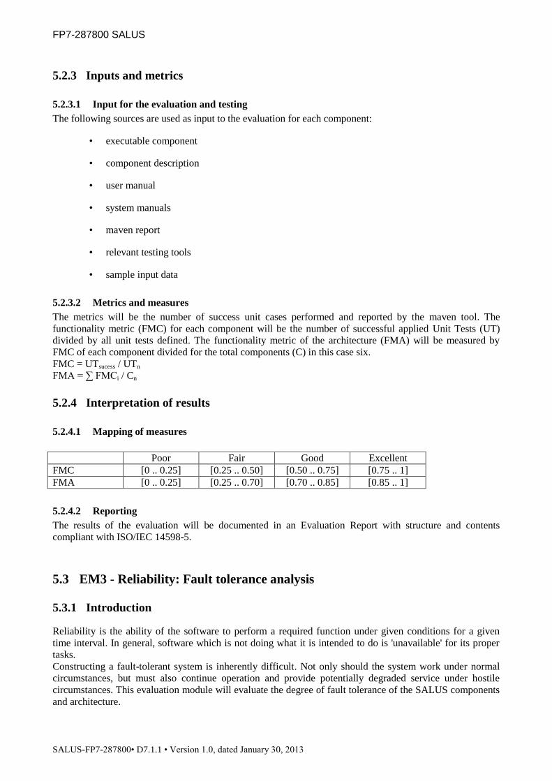
5.2.3.2 Metrics and measures
The metrics will be the number of success unit cases performed and reported by the maven tool. The
functionality metric (FMC) for each component will be the number of successful applied Unit Tests (UT)
divided by all unit tests defined. The functionality metric of the architecture (FMA) will be measured by
FMC of each component divided for the total components (C) in this case six.
FMC = UTsucess / UTn
FMA = ∑ FMCi / Cn
5.2.4 Interpretation of results
5.2.4.1 Mapping of measures
Poor Fair Good Excellent
FMC [0 .. 0.25] [0.25 .. 0.50] [0.50 .. 0.75] [0.75 .. 1]
FMA [0 .. 0.25] [0.25 .. 0.70] [0.70 .. 0.85] [0.85 .. 1]
5.2.4.2 Reporting
The results of the evaluation will be documented in an Evaluation Report with structure and contents
compliant with ISO/IEC 14598-5.
5.3 EM3 - Reliability: Fault tolerance analysis
5.3.1 Introduction
Reliability is the ability of the software to perform a required function under given conditions for a given
time interval. In general, software which is not doing what it is intended to do is 'unavailable' for its proper
tasks.
Constructing a fault-tolerant system is inherently difficult. Not only should the system work under normal
circumstances, but must also continue operation and provide potentially degraded service under hostile
circumstances. This evaluation module will evaluate the degree of fault tolerance of the SALUS components
and architecture.

FP7-287800 SALUS
SALUS-FP7-287800• D7.1.1 • Version 1.0, dated January 30, 2013
Traditionally Reliability is expressed as a number, e.g. 'Mean Time Between Failure (MTBF)'. The number
is either obtained from measurements on the actual system as a whole or it is calculated from known
numbers for the individual components from which the system is to be constructed. But when it comes to
software components the measurements are as a rule either missing, costly to obtain, or difficult to relate to
the reliability aspect of a software product. Hence this evaluation module is restricted to verifying the
number of faults when performing the test cases.
5.3.2 Scope
5.3.2.1 Characteristic(s)
This evaluation module is used to determine the reliability of the SALUS components.
5.3.2.2 Level of evaluation
Level C as defined in ISO/IEC 14598-5 (Appendix 1).
5.3.2.3 Techniques
It will use check list detecting the faults when performing the use-cases.
5.3.2.4 Applicability
The components need to be tested taking into consideration the following fault tolerance requirements:
The system shall avoid loss of data
The system shall be highly reliable in terms of preventing and dealing with possible types of
failure in the Web Service landscape
The component shall continue to function in spite of faulty user inputs
The system shall provide warnings but shall not abort its functionality.
It will be used during system testing and is applicable for all components of the SALUS.
5.3.3 Inputs and metrics
5.3.3.1 Input for the evaluation and testing
The following sources are used as input to the evaluation for each component:
• executable component
• component description
• user manual
• system manuals
• test cases
5.3.3.2 Metrics and measures
The metrics will be the number of Faults (F) detected when performing the Test Cases (TC). The reliability
metric (RMC) for each component will be the number of Faults divided by all test cases performed. The
reliability metric of the architecture (RMA) will be measured by RMC of each component divided for the
total components (C) in this case six.
RMC = F / TCn
RMA = ∑ RMCi / Cn

FP7-287800 SALUS
SALUS-FP7-287800• D7.1.1 • Version 1.0, dated January 30, 2013
5.3.4 Interpretation of results
5.3.4.1 Mapping of measures
Excellent Good Fair Poor
RMC [0 .. 0.25] [0.25 .. 0.50] [0.50 .. 0.75] [0.75 .. 1]
RMA [0 .. 0.25] [0.25 .. 0.70] [0.70 .. 0.85] [0.85 .. 1]
5.3.4.2 Reporting
The results of the evaluation will be documented in an Evaluation Report with structure and contents
compliant with ISO/IEC 14598-5.
5.4 EM4 - Usability: User interface Inspection
5.4.1 Introduction
The user interface of the software will be evaluated in the guidance of IS0 9241[9]:
• Part 12: Presentation of information
• Part 13: User guidance
• Part 14: Menu dialogues
• Part 15: Command dialogues
• Part 16: Direct manipulation dialogues
• Part 17: Form filling dialogues
5.4.2 Scope
5.4.2.1 Characteristic(s)
This evaluation module is used to determine the usability of the SALUS components.
5.4.2.2 Level of evaluation
Level D as defined in ISO/IEC 14598-5 (Appendix 1).
5.4.2.3 Techniques
It will use check lists of conformity of the user interface requirements through user interface inspection.
5.4.2.4 Applicability
It will be used during system testing and is applicable for all components of the SALUS:
5.4.2.4.1 ADE Notification Tool (ANT)
The user interfaces that need to be tested are the following:
ADE Notification Tool – Main GUI
ADE Notification Tool – ADE Alert Pop-Up-Window

FP7-287800 SALUS
SALUS-FP7-287800• D7.1.1 • Version 1.0, dated January 30, 2013
ADE Notification Tool – manual ADE detected
ADE Notification Tool – change ADE Detection Rule
ADE Notification Tool – add ADE Detection Rule
ADE Notification Tool – delete ADE Detection Rule
5.4.2.4.2 ICSR Reporting Tool (IRT)
ICSR Reporting Tool uses two GUIs, each dedicated to a particular function and use cases:
- ICSR form filling (IFF) GUI which is used to complete manually prepopulated ICSR forms and
send them to the regulatory authorities once completed (UC-5.3-1; UC-5.3-2; UC-5.3-5).
- ICSR form management (IFM) GUI which is used to access (a) already completed and previously
sent ICSRs and (b) waiting to be completed ICSRs, and associated functionalities (UC-5.3-3; UC-
5.3-4; UC-5.3-5).
Each GUI will need to be evaluated by end users.
In addition to the standard evaluation criteria described in this deliverable, some evaluation criteria specific
to the SALUS project context will possibly be taken into account: if the GUI (i) facilitates the work of the
GP filling ICSR forms and minimize the time needed to complete them; (ii) maximize the relevant
information that can be used by pharmacovigilance regulatory bodies. The methodology relevant for such an
evaluation remains to be decided in its details. End users satisfaction questionnaires can be used. Measure of
the mean time needed to fill and send and ICSR with and without IRT can also be compared. The quality of
the data available in the ICSR can be evaluated by pharmacovigilance professionals, for instance UMC.
5.4.2.4.3 Safety Analysis Tools
The user interfaces that need to be tested are the following:
Case Series Characterization (CSC) Tool GUI
Temporal Association Screening (TAS) Tool GUI
Temporal Pattern Discovery (TPD) Tool GUI and
The Patient History (PH) Tool GUI
5.4.2.4.4 Semantic Interoperability Layer (SIL) and Semantic Resource Set
The user interfaces that need to be tested are the following:
Common Data Element Repository Export Web GUI
Ontology Mapping Configuration Tool
5.4.2.4.5 Security and Privacy Toolset
The user interface that needs to be tested is the following:
Audit Record Repository GUI
5.4.2.4.6 Common Data Element Repository
The user interface that needs to be tested is the following:
Common Data Element Repository Web GUI
5.4.3 Inputs and metrics
5.4.3.1 Input for the evaluation and testing
The following sources are used as input to the evaluation for each component:

FP7-287800 SALUS
SALUS-FP7-287800• D7.1.1 • Version 1.0, dated January 30, 2013
• executable component
• user manual
• questionnaires (ISO 9241 parts 12 to 17)
5.4.3.2 Metrics and measures
Metrics for each elementary item to be measured are described in “checklists” (questioners described above),
with (y/n/d) possible answer for each question: y means yes, n means no and d means discard because not
applicable. The answer y/n to a question is related to the comparison of the metric value with an expected
value: if the measured value is equal or better than the expected value then the answer is “yes”, otherwise the
answer is “no”.
The usability metric (UMC) for each component will be the number of successful Answers (A) divided by
the number of Check List Items (CL). The usability metric of the architecture (UMA) will be measured by
UMC of each component divided for the total components (C) in this case six.
UMC = Asucess / CLn
UMA = ∑ UMC i / Cn
5.4.4 Interpretation of results
5.4.4.1 Mapping of measures
Poor Fair Good Excellent
UMC [0 .. 0.25] [0.25 .. 0.50] [0.50 .. 0.75] [0.75 .. 1]
UMA [0 .. 0.25] [0.25 .. 0.70] [0.70 .. 0.85] [0.85 .. 1]
5.4.4.2 Reporting
The results of the evaluation shall be documented in an Evaluation Report with structure and contents
compliant with ISO/IEC 14598-5.
5.5 EM5 - Efficiency: Execution Time Measurement
5.5.1 Introduction
In order to identify the root cause of bad application performance a fairly limited set of data is needed. Many
programs spend the majority of their time executing just a few methods. A profiler can help you identify
these hot spots so you can target your performance tuning efforts more effectively. Usually it is enough to
identify the following items in order to track down application hotspots:
• the code fragments used within a test period,
• the time spend within those fragments (min/max/average) and
• the number of fragment executions
However collecting those data is either expensive (in terms of budget or application side effects) or too low
level or just highly proprietary. So for the execution time measurement the Java™ Execution Time
Measurement (JETM) Library will be used for the SALUS evaluation for the selected test cases.

FP7-287800 SALUS
SALUS-FP7-287800• D7.1.1 • Version 1.0, dated January 30, 2013
5.5.2 Scope
5.5.2.1 Characteristic(s)
This evaluation module is used to determine the efficiency of the SALUS components.
5.5.2.2 Level of evaluation
Level D as defined in ISO/IEC 14598-5 (Appendix 1).
5.5.2.3 Techniques
Execution time measurements will be used using Java Execution Time Measurement Library when
applicable.
5.5.2.4 Applicability
It will be used during system testing and is applicable for all components of the SALUS.
5.5.3 Inputs and metrics
5.5.3.1 Input for the evaluation and testing
The following sources are used as input to the evaluation for each component:
• executable component
• component description
• system manuals
5.5.3.2 Metrics and measures
The efficiency metric (EMC) will be the sum of the standard deviation coefficient (SDC) of the number (N)
of the execution time (ET) of a code fragments (CF) divided by the number of code fragments analysed in a
component. The number of code fragments analysed by per component should be greater than 50. The
efficiency metric of the architecture (EMA) will be measured by EMC of each component divided for the
total components (C) in this case six.
M = ET / N
SDC = sqrt { ∑ (ETi - M) / N} / M
EMC = ∑ SDCi / CFn
EMA = ∑ EMCi / Cn
5.5.4 Interpretation of results
5.5.4.1 Mapping of measures
Excellent Good Fair Poor
EMC [0 .. 0.25] [0.25 .. 0.50] [0.50 .. 0.75] [0.75 .. 1]
EMA [0 .. 0.25] [0.25 .. 0.70] [0.70 .. 0.85] [0.85 .. 1]
5.5.4.2 Reporting
The results of the evaluation will be documented in an Evaluation Report with structure and contents
compliant with ISO/IEC 14598-5.

FP7-287800 SALUS
SALUS-FP7-287800• D7.1.1 • Version 1.0, dated January 30, 2013
5.6 EM6 - Maintainability: Inspection of Documents (Checklists)
5.6.1 Introduction
The maintenance process contains the activities and tasks of the maintainer. This process is activated when a
system undergoes modifications to the code and associated documentation due to an error, a deficiency, a
problem, or the need for an improvement or adaptation. The objective is to modify an existing system while
preserving its integrity. Whenever a software product needs modifications, the development process is
invoked to effect and complete the modifications properly.
5.6.2 Scope
5.6.2.1 Characteristic(s)
This evaluation module is used to determine the maintainability of the SALUS components and consequent
architecture.
5.6.2.2 Level of evaluation
Level D as defined in ISO/IEC 14598-5 (Appendix 1).
5.6.2.3 Techniques
It will use a checklist presented below:
Questions YES NO DISCARD
Is it easy to find the code related to the problem or the requested
change?
Is the code understandable?
Is it easy to change the code?
Is it possible to test changes in an isolated manner?
Can a change be made with a low risk of breaking existing
features?
Is the code well documented?
5.6.2.4 Applicability
It will be used during system testing and is applicable for all components of the SALUS.
5.6.3 Inputs and metrics
5.6.3.1 Input for the evaluation and testing
The following sources are used as input to the evaluation for each component:
• System manuals
• Source codes
5.6.3.2 Metrics and measures
Metrics for each elementary item to be measured are described in “checklists”, with (y/n/d) possible answer
for each question: y means yes, n means no and d means discard because not applicable. The answer y/n to a
question is related to the comparison of the metric value with an expected value: if the measured value is
equal or better then the expected value then the answer is “yes”, otherwise the answer is “no”.
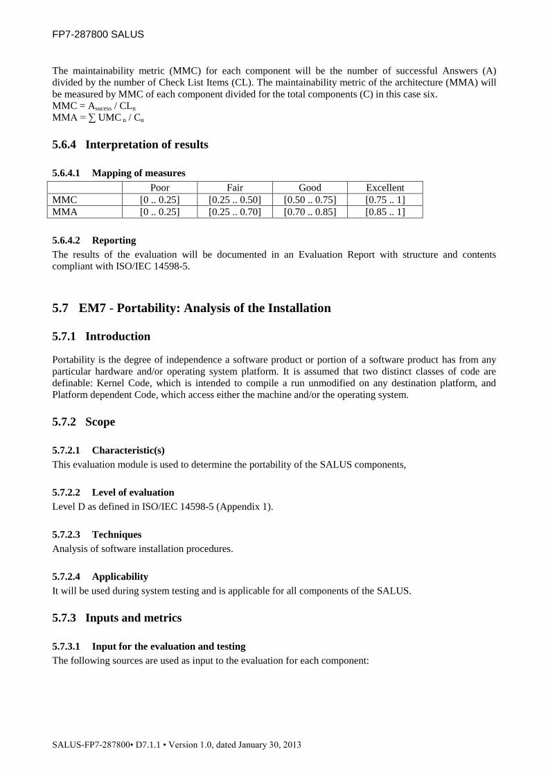
FP7-287800 SALUS
SALUS-FP7-287800• D7.1.1 • Version 1.0, dated January 30, 2013
The maintainability metric (MMC) for each component will be the number of successful Answers (A)
divided by the number of Check List Items (CL). The maintainability metric of the architecture (MMA) will
be measured by MMC of each component divided for the total components (C) in this case six.
MMC = Asucess / CLn
MMA = ∑ UMC n / Cn
5.6.4 Interpretation of results
5.6.4.1 Mapping of measures
Poor Fair Good Excellent
MMC [0 .. 0.25] [0.25 .. 0.50] [0.50 .. 0.75] [0.75 .. 1]
MMA [0 .. 0.25] [0.25 .. 0.70] [0.70 .. 0.85] [0.85 .. 1]
5.6.4.2 Reporting
The results of the evaluation will be documented in an Evaluation Report with structure and contents
compliant with ISO/IEC 14598-5.
5.7 EM7 - Portability: Analysis of the Installation
5.7.1 Introduction
Portability is the degree of independence a software product or portion of a software product has from any
particular hardware and/or operating system platform. It is assumed that two distinct classes of code are
definable: Kernel Code, which is intended to compile a run unmodified on any destination platform, and
Platform dependent Code, which access either the machine and/or the operating system.
5.7.2 Scope
5.7.2.1 Characteristic(s)
This evaluation module is used to determine the portability of the SALUS components,
5.7.2.2 Level of evaluation
Level D as defined in ISO/IEC 14598-5 (Appendix 1).
5.7.2.3 Techniques
Analysis of software installation procedures.
5.7.2.4 Applicability
It will be used during system testing and is applicable for all components of the SALUS.
5.7.3 Inputs and metrics
5.7.3.1 Input for the evaluation and testing
The following sources are used as input to the evaluation for each component:

FP7-287800 SALUS
SALUS-FP7-287800• D7.1.1 • Version 1.0, dated January 30, 2013
• Installation packages
5.7.3.2 Metrics and measures
The metrics will be the number of success installations on the supported operating systems (at least 3 should
be considered). The portability metric (PMC) for each component will be the number of successful
Installations (I) divided by all operating systems (OP) where the component was installed. The portability
metric of the architecture (PMA) will be measured by PMC of each component divided for the total
components (C) in this case six.
PMC = Isucess / OPn
FMA = ∑ FMCn / Cn
5.7.4 Interpretation of results
5.7.4.1 Mapping of measures
Poor Fair Good Excellent
PMC [0 .. 0.25] [0.25 .. 0.50] [0.50 .. 0.75] [0.75 .. 1]
FMA [0 .. 0.25] [0.25 .. 0.70] [0.70 .. 0.85] [0.85 .. 1]
5.7.4.2 Reporting
The results of the evaluation will be documented in an Evaluation Report with structure and contents
compliant with ISO/IEC 14598-5.
6 CONCLUSIONS
The deliverable intends to provide a standard description of the evaluation procedure to undertake in the
SALUS evaluation activities. The description is detailed and covers the practical issues of performing the
evaluation.
The intended use of this deliverable is to be a guide when actually running the SALUS evaluation activities.
For that it contains a level approach to quality characteristics and a flexible view on classifying components
and process information. The evaluation framework is designed to support the evaluation of all SALUS
components without need for modification of its basic principles. This will give a more balanced and equal
evaluation result of all the components of the SALUS architecture.
The use of the functional and non-functional evaluation criteria modules detailed in chapter 5, with the
description of techniques and their evaluation criteria, ensure that the SALUS components evaluations can be
repeatable, reproducible and objective.
The next activities will be to finalize the draft test cases (presented in APPENDIX 2), run these test cases,
implement unit tests, to measure execution times from the components, and to inspect the components
documentation and software installation procedures. D7.1.2 and D7.1.3 will include the evaluation report
with the results of the evaluation (report the evaluation) with the analysis of all measured results facing the
functional and non-functional criteria defined in this document.

FP7-287800 SALUS
SALUS-FP7-287800• D7.1.1 • Version 1.0, dated January 30, 2013
7 REFERENCES
[1] ISO/IEC CD 25040: Software engineering - Software product Quality Requirements and Evaluation (SQuaRE)
- Evaluation reference model and guide, Switzerland: International Organization for Standardization.
[2] ISO/IEC 14598-6: Software engineering -- Product evaluation -- Part 6: Documentation of evaluation modules.
Geneva, Switzerland: International Organization for Standardization.
[3] ISO/IEC 9126-1: Software Engineering-Software product quality-Part 1 : Quality model. Geneva, Switzerland:
International Organization for Standardization.
[4] ISO/IEC. 1999a. ISO/IEC 14598-1: Software product evaluation-Part 1 : General overview. Geneva,
Switzerland: International Organization for Standardization.
[5] ISO/IEC CD 25010: Software engineering-Software product Quality Requirements and Evaluation (SQuaRE)
Quality model, Switzerland: International Organization for Standardization.
[6] ISO/IEC CD 25030: Software engineering -- Software product Quality Requirements and Evaluation
(SQuaRE) -- Quality requirements, Switzerland: International Organization for Standardization.
[7] ISO/IEC. 1999a. ISO/IEC 14598-5: Information technology -- Software product evaluation -- Part 5: Process
for evaluators. Geneva, Switzerland: International Organization for Standardization.
[8] ISO/IEC CD 8402-1, Quality Concepts and Teminology Part One: Generic Terms and Definitions,
international Standards Organisation, December 1990.
[9] ISO 9241 Ergonomics of Human System Interaction, Geneva, Switzerland: International Organization for
Standardization.
[10] Maven is a software project management and comprehension tool, http://maven.apache.org/
[11] Java™ Execution Time Measurement Library, http://jetm.void.fm/

FP7-287800 SALUS
SALUS-FP7-287800• D7.1.1 • Version 1.0, dated January 30, 2013
APPENDIX 1. EVALUATION LEVELS
Evaluation levels define the depth or thoroughness of the evaluation in terms of evaluation techniques to be
applied and evaluation results to be achieved. As a consequence evaluation at different levels gives different
level of confidence in the quality of the software product. This evaluation levels where extracted from
ISO/IEC 25040 and are used as guide in this deliverable.
For a relevant quality characteristic, the risks and consequences involved by the non conformity of the
product to requirements relating to this characteristic, as well as benefits from high quality, should be
assessed for all the relevant aspects. For some of these aspects, the tables below provide the relationship
between risks and levels to be selected.
Safety aspects
Level A Many people killed
Level B Threat to human lives
Level C Damage to property; threat of injury to people
Level D Small damage to property; no risk to people
Economy aspects
Level A Financial disaster (company will not survive)
Level B Large economic loss (company endangered)
Level C Significant economic loss (company affected)
Level D Negligible economic loss
Security aspects
Level A Protection of strategic data and services
Level B Protection of critical data and services
Level C Protection against error risk
Level D No specific risk identified
Environment related aspects
Level A Unrecoverable environmental damage
Level B Recoverable environmental damage
Level C Local pollution
Level D No environmental risk
Table 5 – Evaluation levels according to ISO/IEC 25040
Table 4 shows to which level the evaluation techniques are attached. The + notation in the table indicates
the additional techniques when moving to the next level. Level D Level C Level B Level A
Functionality Functional testing
(black box)
+ inspection of
documents
(check lists)
+ component
testing (white
box)
+ formal proof
Reliability Programming
Language facilities
+ fault tolerance
analysis
+reliability
growth model
+ formal proof
Usability User interface
inspection
+ conformity to
interface
standards
+ laboratory
testing
+ user mental
model
Efficiency Execution time
measurement
+ benchmark
testing
+ algorithmic
complexity
+ performance
profiling analysis
Maintainability Inspection of
documents (check
lists)
+ static analysis + analysis of
Development
process
+ traceability
evaluation
Portability Analysis of
installation
+ conformity to
programming
rules
+ environment
Constraints
evaluation
+ program design
evaluation
Table 6 Guideline for selecting evaluation techniques

FP7-287800 SALUS
SALUS-FP7-287800• D7.1.1 • Version 1.0, dated January 30, 2013
APPENDIX 2. TEST CASE DESCRIPTIONS
7.1 Templates
7.1.1 Use Case Template
Description
Parent
Scope
Actor(s)
Goal
Trigger
Frequency
Preconditions
Minimal Post-
Conditions
Success Post-
Conditions
7.1.2 Use-Case (B)asic flows
#ID Description
B1
B2
B3
..
..
7.1.3 Use-Case (A)lternative flows
#ID Description
7.1.4 Fault Cases
These will be used for executing the test scenarios for fault tolerance test:
#ID Fault Fault Tolerance Requirement Description

FP7-287800 SALUS
SALUS-FP7-287800• D7.1.1 • Version 1.0, dated January 30, 2013
7.1.5 (S)cenarios to be tested
#ID Flows
S1
..
7.1.6 Execution
#ID Scenario
Variables Expected
Result
TC1 S1
TC2 ..
7.2 Test Case Definitions for Common Data Element Repository
7.2.1 TC-4.2-1 Import a Content Model to CDE Repository
Description This use case is for importing a Content Model to the Common Data Element (CDE)
Repository. A content model can be in various formats: including UML Model, Content
Models represented through an XSD model (like HL7 CDA templates or CDISC ODM
message specifications) and supporting schematrons, and through ADL 1.4 (like CEN
13606 archetypes defined on 13606 RM), and a local domain ontology (e.g. data definition
ontology). The final objective is to represent this Model as an ontology, annotate it with
existing CDEs (through “UC-4.2-2 Annotate a Content Model with CDEs in CDE
Repository”) in SALUS Core Ontology if possible, and create new CDEs if necessary to
extend the SALUS Core Ontology.
Parent -
Included sub-use
cases
-
Extended sub-
use cases
-
Scope CDE Repository
Actor(s) CDE Repository User (Domain Expert)
Goal Importing a new content model to enrich Common Data Element Set maintained within the
CDE Repository.
Trigger This use case is initiated by a CDE Repository User (Domain Expert) when a new content
model needs to be added to the CDE Repository to extend the CDE Set if necessary.

FP7-287800 SALUS
SALUS-FP7-287800• D7.1.1 • Version 1.0, dated January 30, 2013
Frequency Whenever a new content model needs to be added to the CDE Repository, approximately
once/twice a year.
Minimal Post
conditions
CDE Repository informs the user (Domain Expert) about the result of the import
operation.
Success Post-
Conditions
The Content Model is successfully imported to the CDE Repository as a Content Model
Ontology, and ready to be annotated with the existing CDEs in the CDE Repository
7.2.1.1 Use-Case (B)asic flows
#ID Description
B1 Domain Expert intends to import a new content model and selects the type of the content and points to the
location where the content model resides.
B2 CDE Repository retrieves the model, parses it (them) and imports this content as a new Content Model
Ontology in the CDE Repository.
B3 Domain Expert views the result, if necessary modifies the ontology and confirms the import operation.
B4 The final Content Model Ontology is saved to be used by other SALUS components
7.2.1.2 Use-Case (A)lternative flows
#ID Description
A1 CDE Repository is unable to access or parse the content model and supporting files such as schematrons.
CDE Repository informs the Domain Expert about the problem and present guidance to solve the problem.
A2 Domain Experts views the result, and cancels the import operation. The system returns to home screen.
A3 The tool cannot save the imported content model to the repository since the repository is temporarily
unavailable, the system affected should either retry later to communicate with the repository or send back an
error message
7.2.1.3 Fault Cases
These will be used for executing the test scenarios for fault tolerance test:

FP7-287800 SALUS
SALUS-FP7-287800• D7.1.1 • Version 1.0, dated January 30, 2013
#ID Fault Fault Tolerance Requirement Description
FT1 Inaccessible content model CDE Repository is unable to access the content model and
supporting files such as schematrons. CDE Repository informs the
Domain Expert about the problem and present guidance to solve the
problem.
FT2 Unsupported Content Model Format CDE Repository is unable to parse the content model and supporting
files such as schematrons. CDE Repository informs the Domain
Expert about the problem and present guidance to solve the problem.
FT3 CDE Repository is down The tool cannot save the imported content model to the repository
since the repository is temporarily unavailable, the system affected
should either retry later to communicate with the repository or send
back an error message
7.2.1.4 (S)cenarios to be tested
#ID Flows
S1 B1 B2 B3 B4
S2 B1 B2 A2
S3 B1 A1
S4 B1 B2 B3 A3
7.2.1.5 Execution (Functionality and Fault Tolerance Tests)
#ID Scenario
Variables Expected
Result
Content
Model Type
Cancel Fault
TC1 S1 UML No None B4
TC2 S1 XSD No None B4
TC3 S1 ADL 1.4 No None B4
TC4 S2 UML Yes None A2
TC5 S2 XSD Yes None A2
TC6 S2 ADL 1.4 Yes None A2
TC7 S3 UML No FT1 A1
TC8 S3 XSD No FT1 A1
TC9 S3 ADL 1.4 No FT1 A1

FP7-287800 SALUS
SALUS-FP7-287800• D7.1.1 • Version 1.0, dated January 30, 2013
TC10 S3 UML No FT2 A1
TC11 S3 XSD No FT2 A1
TC12 S3 ADL 1.4 No FT2 A1
TC13 S4 UML No FT3 A3
TC14 S4 XSD No FT4 A3
TC15 S4 ADL 1.4 No FT4 A3
7.2.2 TC-4.2-2 Annotate a Content Model with CDEs in CDE Repository
Description The CDE Repository supports a mechanism to upload new Content Models to the CDE
Repository. The purpose is to further populate the CDE Repository by identifying the need
for new CDEs and adding new CDEs, and link the building blocks of Content Models to
the existing CDEs in SALUS Core Ontology paving the way to Semantic interoperability.
Parent -
Included sub-use
cases
UC-4.2-1 Import a Content Model to CDE Repository
UC-4.2-4 Browse/View CDEs
Extended sub-
use cases
-
Scope CDE Repository
Actor(s) CDE Repository User (Domain Expert)
Goal The goal of this use case is to uplift the content model to CDE repository to be able to
annotate the semantic representation of the Content Model (Content Model Ontology) with
the available CDEs in SALUS Core Ontology and create new CDEs when necessary
Trigger This use case is initiated by a CDE Repository User (Domain Expert) when a new Content
Model needs to be added to CDE Repository.
Frequency Whenever a new Content Model is added to CDE Repository, approximately once/twice a
year
Minimal Post
conditions
CDE Repository informs the Domain Expert about the result of the annotation operation
Success Post-
Conditions
1. The CDEs corresponding to the building blocks of Content Model have been
identified and the Content Model Ontology has been annotated with these CDEs.
2. If necessary new CDEs have been curated and added to the CDE Repository and
hence to the SALUS Core Ontology

FP7-287800 SALUS
SALUS-FP7-287800• D7.1.1 • Version 1.0, dated January 30, 2013
7.2.2.1 Use-Case (B)asic flows
#ID Description
B1 The candidate CDEs in the parsed Content Model Ontology are identified
B2 Through semantic search on existing CDEs, identified CDEs in B1 are mapped to the already existing CDEs.
[UC-4.2-3 Search CDEs]
B3 The matching CDEs are ranked and presented to the user based on their similarity through terminology
matching and linguistic analysis
B4 For each matching, the user checks the similarity through the GUI and selects one mapping for the identified
CDE.
B5 The mappings are stored in the CDE annotations from the identified CDEs of the imported content model to
the CDEs of the CDE repository.
7.2.2.2 Use-Case (A)lternative flows
#ID Description
A1 Domain Expert views the mappings one by one, and cancels the annotation operation at a point. The system
returns to home screen by rolling back the annotations performed up to that point for that content model.
A2 For an identified CDE, no mapping can be suggested by the system. The user requests that CDE to be added
to the already existing CDE set.
7.2.2.3 Fault Cases
These will be used for executing the test scenarios for fault tolerance test:

FP7-287800 SALUS
SALUS-FP7-287800• D7.1.1 • Version 1.0, dated January 30, 2013
#ID Fault Fault Tolerance Requirement Description
FT1 CDE Repository is down The tool cannot save the annotations/mappings to the repository
since the repository is temporarily unavailable, the system affected
should either retry later to communicate with the repository or send
back an error message.
7.2.2.4 (S)cenarios to be tested
#ID Flows
S1 B1 B2 B3 B4 B5
S2 B1 B2 B3 B4 A1
S3 B1 B2 B3 A1
S4 B1 B2 B3 A2 B5
7.2.2.5 Execution (Functionality and Fault Tolerance Tests)
#ID Scenario
Variables Expected
Result
Cancel Fault
TC1 S1 No None B5
TC2 S1 No FT1 FT1
TC3 S2 Yes None A1
TC4 S2 Yes FT1 FT1
TC5 S3 Yes None A1
TC6 S3 Yes FT1 FT1
TC7 S4 No None B5
TC8 S4 No FT1 FT1
7.2.3 TC-4.2-3 Search CDEs
Description CDE Repository User (Domain Expert) can search the CDE Repository for CDEs
matching the search criteria.
Parent -
Included sub-use -

FP7-287800 SALUS
SALUS-FP7-287800• D7.1.1 • Version 1.0, dated January 30, 2013
cases
Extended sub-
use cases
-
Scope CDE Repository
Actor(s) CDE Repository User (Domain Expert)
Goal Finding the CDEs in the CDE Repository matching the search criteria.
Trigger The CDE Repository User can trigger this action from the CDE Repository Menu
Frequency Whenever a new Content Model is to be added to SALUS Semantic Interoperability
Framework, approximately once/twice a year
Whenever initiated by the CDE Repository User
Minimal Post
conditions
The user is informed about the status of the search operation.
Success Post-
Conditions
Matching CDEs are discovered and presented to the CDE Repository User
7.2.3.1 Use-Case (B)asic flows
#ID Description
B1 The CDE Repository User specifies the search criteria, which could be keywords, selected terminology codes,
or a candidate CDE
B2 Based on the specified criteria, CDE Repository is searched and the matching CDEs are displayed to the user
7.2.3.2 Use-Case (A)lternative flows
#ID Description
A1 Domain Expert cancels the search while the system is in progress of search. The system returns to home
search screen.
A2 Based on the specified criteria, CDE Repository is searched and no matching CDEs are found. Appropriate
message is shown to the Domain Expert to repeat the search with different search criteria.
7.2.3.3 Fault Cases
These will be used for executing the test scenarios for fault tolerance test:

FP7-287800 SALUS
SALUS-FP7-287800• D7.1.1 • Version 1.0, dated January 30, 2013
#ID Fault Fault Tolerance Requirement Description
FT1 CDE Repository is down The tool cannot search through the repository since the repository is
temporarily unavailable, the system affected should either retry later
to communicate with the repository or send back an error message.
7.2.3.4 (S)cenarios to be tested
#ID Flows
S1 B1 B2
S2 B1 A1
S3 B1 A2
7.2.3.5 Execution (Functionality and Fault Tolerance Tests)
#ID Scenario
Variables Expected
Result
Cancel Fault
TC1 S1 No None B2
TC2 S1 No FT1 FT1
TC3 S2 Yes None A1
TC4 S2 Yes FT1 FT1
TC5 S3 No None A2
TC6 S3 No FT1 FT1
7.2.4 TC-4.2-4 Browse/View CDEs
Description CDE Repository User can browse the CDE Repository, and view the details of a selected
CDE
Parent -
Included sub-use
cases
-
Extended sub-
use cases
UC-4.2-3 Search CDEs
Scope CDE Repository
Actor(s) CDE Repository User (Domain Expert)
Goal
Browsing CDE Repository and viewing the details of a selected CDE

FP7-287800 SALUS
SALUS-FP7-287800• D7.1.1 • Version 1.0, dated January 30, 2013
Trigger The CDE Repository User can trigger this action from the CDE Repository Menu
After searching a CDE through Search CDEs.
Frequency Whenever initiated by the CDE Repository User
Minimal Post
conditions
The user is informed about the status of the search operation.
Success Post-
Conditions
The CDE Repository User can successfully browse through different categories, and select
and view the detailed attributes of the selected CDEs through CDE Repository Interface
7.2.4.1 Use-Case (B)asic flows
#ID Description
B1 The CDE Repository User can search a specific CDE through “UC-4.2-3 Search CDEs” or Browse through
the categories available in the CDE Repository
B2 The CDE Repository User Interface displays the detailed attributes of the selected CDE. The CDE Repository
User can filter the attributes to be displayed as a configuration.
B3 If required, the CDE Repository User can navigate through the links between the CDEs (such as parent CDE)
7.2.4.2 Use-Case (A)lternative flows
#ID Description
A1 Domain Expert cancels the operation while the system is in progress of browsing. The system returns to home
browser screen.
7.2.4.3 Fault Cases
These will be used for executing the test scenarios for fault tolerance test:

FP7-287800 SALUS
SALUS-FP7-287800• D7.1.1 • Version 1.0, dated January 30, 2013
#ID Fault Fault Tolerance Requirement Description
FT1 CDE Repository is down The tool cannot browse through the repository since the repository is
temporarily unavailable, the system affected should either retry later
to communicate with the repository or send back an error message.
7.2.4.4 (S)cenarios to be tested
#ID Flows
S1 B1 B2 B3
S2 B1 B2 A1
S3 B1 B2 B3 A1
7.2.4.5 Execution (Functionality and Fault Tolerance Tests)
#ID Scenario
Variables Expected
Result
Cancel Fault
TC1 S1 No None B3
TC2 S1 No FT1 FT1
TC3 S2 Yes None A1
TC4 S2 Yes FT1 FT1
TC5 S3 Yes None A1
TC6 S3 Yes FT1 FT1
7.3 Test Case Definitions for Semantic Interoperability Layer (SIL) and
Semantic Resource Set
7.3.1 TC-4.3-1 Export SALUS Core Ontology from CDE Repository
Description
The semantic model as an ontology is created from the available CDEs in the CDE
Repository, and exported for the use of other SALUS components (e.g. Semantic
Interoperability Layer components)
Parent -
Scope SALUS Semantic Resource Set
Actor(s) CDE Repository, CDE Repository User (Domain Expert)

FP7-287800 SALUS
SALUS-FP7-287800• D7.1.1 • Version 1.0, dated January 30, 2013
Goal Creating the semantic model of the available CDEs in the CDE Repository as an
ontology
Trigger The CDE Repository User (Domain Expert) can trigger this action from the CDE
Repository Menu
Frequency Whenever initiated by the CDE Repository User (Domain Expert)
Preconditions The Domain Expert should be logged in to the CDE Repository
Minimal Post-
Conditions
An error message is displayed if there is a connection error with the CDE
Repository.
Success Post-
Conditions
The semantic model as an ontology is created from the available CDEs in the CDE
Repository, and served within the system for further use.
7.3.1.1 Use-Case (B)asic flows
#ID Description
B1 The Domain Expert intends to create the SALUS Core Ontology from the CDE Repository.
B2 The Domain Expert configures semantic model creation process if necessary (for example some uninteresting
attributes can be eliminated)
B3 The ontology based on the CDEs in the Repository is exported to be used by Semantic Interoperability Layer
and related SALUS components
7.3.1.2 Use-Case (A)lternative flows
#ID Description
A1 The Domain Expert cancels the export.
7.3.1.3 Fault Cases
These will be used for executing the test scenarios for fault tolerance test:
#ID Fault Fault Tolerance Requirement Description
FT1 CDE Repository is down The Domain Expert cannot export the SALUS Core Ontology
because the CDE Repository is unavailable.
The application informs the user about the issue and allows him to
retry or cancel the export.

FP7-287800 SALUS
SALUS-FP7-287800• D7.1.1 • Version 1.0, dated January 30, 2013
7.3.1.4 (S)cenarios to be tested
#ID Flows
S1 B1 B2 B3
S2 B1 A1
S3 B1 B2 A1
7.3.1.5 Execution
#ID Scenario
Variables Expected
Result
Cancel Fault
TC1 S1 No None B3
TC2 S1 No FT1 FT1
TC3 S2 Yes None A2
TC4 S2 Yes FT1 FT1
TC5 S3 Yes None A2
TC6 S3 Yes FT1 FT1
7.3.2 TC-4.3-2 Map Content Model Ontologies to SALUS Core Ontology
Description
This use case aims to serve to the creation of SALUS Semantic Resource Set, by
creating the mapping rules between the Content Model Ontologies and SALUS
Core Ontology (which is the semantic representation of SALUS CDEs). It is
assumed that Content Model Ontologies have already been created by “UC-4.2-1
Import a Content Model to CDE Repository” use case, and optionally has been
annotated with the already existing CDEs in the repository through the “UC-4.2-2
Annotate a Content Model with CDEs in CDE Repository” use case. The output is
the Mapping Rules defined between Content Model Ontologies and SALUS Core
Ontology, which altogether constitute to SALUS Semantic Resource Set.
Parent -
Scope SALUS Semantic Resource Set
Actor(s) CDE Repository User (Domain Expert)
Goal Creating the mapping rules between Content Model Ontologies and SALUS Core
Ontology, to extend SALUS Semantic Resource Set
Trigger The Domain Expert can trigger this action.
Frequency Whenever initiated by the Domain Expert
Preconditions SALUS Core Ontology is created and saved through the “UC-4.3-1 Export
SALUS Core Ontology from CDE Repository” use case

FP7-287800 SALUS
SALUS-FP7-287800• D7.1.1 • Version 1.0, dated January 30, 2013
Content Model Ontologies have already been created and saved by “UC-4.2-1
Import a Content Model to CDE Repository” use case
Optionally, Content Model Ontology has been annotated with the already existing
CDEs in the repository through the “UC-4.2-2 Annotate a Content Model with
CDEs in CDE Repository” use case
Minimal Post-
Conditions Domain Expert is informed about the results of the mapping operation
Success Post-
Conditions
Mapping rules between Content Model Ontologies and SALUS Core Ontology are
created and saved to extend SALUS Semantic Resource Set
7.3.2.1 Use-Case (B)asic flows
#ID Description
B1 Domain Expert selects the pre-loaded (annotated) Content Model Ontology and the ontology is displayed to
the user.
B2 Domain Expert selects an element (i.e. a class) from the source Content Model Ontology.
B3 Domain Expert defines mapping rules from the selected Content Model Ontology class to class(es) of the
target SALUS Core Ontology.
B4 If Annotated Content Model Ontology is loaded, then, the tool will propose candidate mapping rules semi-
automatically to ease the mapping process
B5 If Content Model Ontology is not annotated, or the candidate mapping rules are not approved by the Domain
Expert, Domain Expert can define the mapping rules manually
B6 Domain Expert repeats steps B2-B5 for each Content Model Ontology class that he wants to define mapping
to the SALUS Core Ontology.
B7 Domain Expert reviews and confirms the overall mapping
7.3.2.2 Use-Case (A)lternative flows
#ID Description
A1 The system cannot create the mapping definition.
A2 Domain Expert is informed about the mapping problem, and asked to either update the mapping definition
according to the presented error report or cancel this specific mapping.
A3 The Domain Expert updates the mapping definition
A4 The Domain Expert cancels the mapping
7.3.2.3 Fault Cases
These will be used for executing the test scenarios for fault tolerance test:

FP7-287800 SALUS
SALUS-FP7-287800• D7.1.1 • Version 1.0, dated January 30, 2013
#ID Fault Fault Tolerance Requirement Description
FT1 Mapping Tool unavailable The mapping tool is not responsive.
The system returns an error message stating that the mapping tool is
unavailable.

FP7-287800 SALUS
SALUS-FP7-287800• D7.1.1 • Version 1.0, dated January 30, 2013
7.3.2.4 (S)cenarios to be tested
#ID Flows
S1 B1 B2 B3 B4 B6 B7
S2 B1 B2 B3 B4 B6 A4
S3 B1 B2 B3 B5 B6 B7
S4 B1 B2 B3 B5 B6 A4
S5 B1 B2 B3 A1 A2 A3
S6 B1 B2 B3 A1 A2 A4
7.3.2.5 Execution
#ID Scenario
Variables Expected
Result
Fault
TC1 S1 None B7
TC2 S1 FT1 FT1
TC3 S2 None A4
TC4 S2 FT1 FT1
TC5 S3 None B7
TC6 S3 FT1 FT1
TC7 S4 None A4
TC8 S4 FT1 FT1
TC9 S5 None A3
TC10 S5 FT1 FT1
TC11 S6 None A4
TC12 S6 FT1 FT1

FP7-287800 SALUS
SALUS-FP7-287800• D7.1.1 • Version 1.0, dated January 30, 2013
7.3.3 TC-4.3-3 Include a Terminology System to the SALUS Semantic Resource Set
Description
This use case is for including a Terminology System (a subset, or the complete
content), which did not exist in the Semantic resource set of SALUS previously. A
terminology system will be represented as an ontology to extend the SALUS
Semantic Resource Set. The terminology system to be imported can be an
international one, or proprietary.
Parent -
Scope SALUS Semantic Resource Set
Actor(s) Terminology Expert
Goal Enriching the SALUS Semantic Resource Set with Terminology Systems
Trigger This use case is initiated by a Terminology Expert when a new Terminology
System needs to be added to extend the SALUS Semantic Resource Set.
Frequency Whenever a new Terminology System needs to be added, approximately
once/twice a year.
Preconditions Terminology Expert is logged on.
Minimal Post-
Conditions SIL informs the Terminology Expert about the result of the import operation.
Success Post-
Conditions
The terminology system is successfully imported to the SALUS Semantic
Resource Set, aligned with the SALUS Core Ontology and ready for mapping with
other available terminology systems.
7.3.3.1 Use-Case (B)asic flows
#ID Description
B1 Terminology Expert intends to include a new terminology system. Either a subset or the complete content of a
terminology system can be included.
B2 Terminology Expert points to the location where terminology system to be imported resides.
B3 The system retrieves the actual content of the terminology system and if it is not represented already as an
ontology, imports this content as a new ontology and includes it to the SALUS Semantic Resource Set.
B4 (Optional) Terminology Expert fine tunes the generated terminology ontology (e.g. change of a designation,
adding/modifying a semantic relationship between two coded terms).
B5 Terminology Expert views the result and confirms the operation.
B6 Terminology Expert defines (or reviews and confirms the existing) rules to align the Terminology System
Ontology with the SALUS Core Ontology; these rules are saved to be used by the system when necessary.
7.3.3.2 Use-Case (A)lternative flows
#ID Description
A1 The Terminology Expert references a public terminology repository.
A2 The Terminology Expert references a local terminology file.
7.3.3.3 Fault Cases
These will be used for executing the test scenarios for fault tolerance test:

FP7-287800 SALUS
SALUS-FP7-287800• D7.1.1 • Version 1.0, dated January 30, 2013
#ID Fault Fault Tolerance Requirement Description
FT1 Terminology repository unavailable When the preferred include option is access to a public terminology
repository, the remote server is unavailable or a network error occurs
during access. SIL informs the Terminology Expert about the
problem, and asks him to either retry or cancel the operation.
FT2 Terminology file unavailable When the preferred import option is providing a local terminology
file, SIL is unable to access or parse the file content. SIL informs the
Terminology Expert about the problem, and asks him to either
update the file according to the presented error report or cancel the
operation.

FP7-287800 SALUS
SALUS-FP7-287800• D7.1.1 • Version 1.0, dated January 30, 2013
7.3.3.4 (S)cenarios to be tested
#ID Flows
S1 B1 B2 A1 B3 B4 B5 B6
S2 B1 B2 A1 B3 B5 B6
S3 B1 B2 A2 B3 B4 B5 B6
S4 B1 B2 A2 B3 B5 B6
7.3.3.5 Execution
#ID Scenario
Variables Expected
Result
Fault
TC1 S1 None B6
TC2 S1 FT1 FT1
TC3 S2 None B6
TC4 S2 FT1 FT1
TC5 S3 None B6
TC6 S3 FT2 FT2
TC7 S4 None B6
TC8 S4 FT2 FT2
7.3.4 TC-4.3-4 Map a Terminology System Code to Other Terminology System Codes
Description This use case is for mapping a single code from a terminology system to code(s)
from other terminology systems.
Parent -
Scope SALUS Semantic Resource Set
Actor(s) Terminology Expert
Goal
Defining the mapping of a single code from a terminology system to code(s) from
other terminology systems and adding the mappings to the SALUS Semantic
Resource Set.
Trigger This use case is initiated by a Terminology Expert after a new Terminology
System has been added to the SALUS Semantic Resources Set.
Frequency After a new Terminology System is added to SALUS Semantic Resources Set.
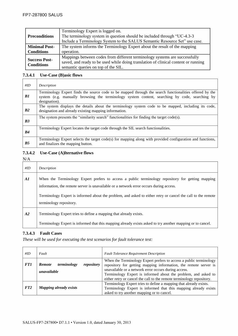
FP7-287800 SALUS
SALUS-FP7-287800• D7.1.1 • Version 1.0, dated January 30, 2013
Preconditions
Terminology Expert is logged on.
The terminology system in question should be included through “UC-4.3-3
Include a Terminology System to the SALUS Semantic Resource Set” use case.
Minimal Post-
Conditions
The system informs the Terminology Expert about the result of the mapping
operation.
Success Post-
Conditions
Mappings between codes from different terminology systems are successfully
saved, and ready to be used while doing translation of clinical content or running
semantic queries on top of the SIL.
7.3.4.1 Use-Case (B)asic flows
#ID Description
B1 Terminology Expert finds the source code to be mapped through the search functionalities offered by the
system (e.g. manually browsing the terminology system content, searching by code, searching by
designation).
B2 The system displays the details about the terminology system code to be mapped, including its code,
designation and already existing mapping information.
B3 The system presents the “similarity search” functionalities for finding the target code(s).
B4 Terminology Expert locates the target code through the SIL search functionalities.
B5 Terminology Expert selects the target code(s) for mapping along with provided configuration and functions,
and finalizes the mapping button.
7.3.4.2 Use-Case (A)lternative flows
N/A
#ID Description
A1 When the Terminology Expert prefers to access a public terminology repository for getting mapping
information, the remote server is unavailable or a network error occurs during access.
Terminology Expert is informed about the problem, and asked to either retry or cancel the call to the remote
terminology repository.
A2 Terminology Expert tries to define a mapping that already exists.
Terminology Expert is informed that this mapping already exists asked to try another mapping or to cancel.
7.3.4.3 Fault Cases
These will be used for executing the test scenarios for fault tolerance test:
#ID Fault Fault Tolerance Requirement Description
FT1 Remote terminology repository
unavailable
When the Terminology Expert prefers to access a public terminology
repository for getting mapping information, the remote server is
unavailable or a network error occurs during access.
Terminology Expert is informed about the problem, and asked to
either retry or cancel the call to the remote terminology repository.
FT2 Mapping already exists Terminology Expert tries to define a mapping that already exists.
Terminology Expert is informed that this mapping already exists
asked to try another mapping or to cancel.

FP7-287800 SALUS
SALUS-FP7-287800• D7.1.1 • Version 1.0, dated January 30, 2013
7.3.4.4 (S)cenarios to be tested
#ID Flows
S1 B1 B2 B3 B4 B5
S2 B1 B2 B3 B4 A1
S3 B1 B2 B3 B4 A2 B5
7.3.4.5 Execution
#ID Scenario
Variables Expected
Result
Cancel Fault
TC1 S1 N/A None B5
TC2 S2 N/A None A1
TC3 S2 N/A FT1 FT1
TC4 S3 No None B5
TC5 S3 Yes None B5
TC6 S3 Yes FT2 FT2
7.3.5 TC-4.3-5 Include an External Domain Ontology to the Semantic Resource Set
Description
This use case is for importing an external domain ontology (such as Drug
Ontology, Disease Ontology) to align with and extend the SALUS Semantic
Resource Set. The aim is to extend the reasoning capabilities of Semantic
Interoperability Layer and related components of SALUS through extended
domain knowledge.
Parent -
Scope SALUS Semantic Resource Set
Actor(s) Domain Expert
Goal Importing external domain ontology to extend SALUS Semantic Resource Set
Trigger This use case is initiated by a Domain Expert when a new external domain
ontology needs to be added to SALUS Semantic Resource Set
Frequency Whenever a new external domain ontology needs to be added to SALUS Semantic
Resource Set, approximately once/twice a year
Preconditions Domain Expert is logged on.
The external domain ontology to be imported is already created and accessible.
Minimal Post-
Conditions SIL informs the Domain Expert about the result of the import operation.

FP7-287800 SALUS
SALUS-FP7-287800• D7.1.1 • Version 1.0, dated January 30, 2013
Success Post-
Conditions
The external ontology is successfully included in the SALUS Semantic Resource
Set, and ready to be aligned with the SALUS Core Ontology.
7.3.5.1 Use-Case (B)asic flows
#ID Description
B1 Domain Expert points to the location where external domain ontology resides.
B2 The system includes this ontology as a new ontology to the SALUS Semantic Resource Set.
B3 Content of the external domain ontology is presented to the Domain Expert to get confirmation.
7.3.5.2 Use-Case (A)lternative flows
#ID Description
A1 The system is unable to access or parse the file content.
Domain Expert is informed about the problem, and guided to solve the problem.
7.3.5.3 Fault Cases
These will be used for executing the test scenarios for fault tolerance test:
#ID Fault Fault Tolerance Requirement Description
FT1 Unable to process file The system is unable to access or parse the file content.
Domain Expert is informed about the problem, and guided to solve
the problem.

FP7-287800 SALUS
SALUS-FP7-287800• D7.1.1 • Version 1.0, dated January 30, 2013
7.3.5.4 (S)cenarios to be tested
#ID Flows
S1 B1 B2 B3
S2 B1 A1 B2 B3
7.3.5.5 Execution
#ID Scenario
Variables Expected
Result
Fault
TC1 S1 None B3
TC2 S2 None B3
TC3 S2 FT1 FT1
7.3.6 TC-4.3-6 Align an External Domain Ontology with SALUS Core Ontology
Description This use case is for aligning an external domain ontology, which is included to the
SIL Semantic Resource Set, with the SALUS Core Ontology.
Parent -
Scope SALUS Semantic Resource Set
Actor(s) Domain Expert
Goal Aligning an external domain ontology with the SALUS Core Ontology to extend
reasoning capabilities.
Trigger This use case is initiated by a Domain Expert when a new external domain
ontology is added to SALUS Semantic Resource Set.
Frequency Whenever a new external domain ontology needs to be added to SALUS Semantic
Resource Set, approximately once/twice a year
Preconditions
Domain Expert is logged on to the SIL.
The ontology in question is included through “UC-4.3-5 Include an External
Domain Ontology to the Semantic Resource Set”
Minimal Post-
Conditions Domain Expert is informed about the result of the mapping operation.
Success Post-
Conditions
The external domain ontology is successfully mapped and aligned with the
SALUS Core Ontology.

FP7-287800 SALUS
SALUS-FP7-287800• D7.1.1 • Version 1.0, dated January 30, 2013
7.3.6.1 Use-Case (B)asic flows
#ID Description
B1 Domain Expert selects the external domain ontology to be aligned with the SALUS Core Ontology.
B2 Domain Expert selects an element (i.e. a class) from the external domain ontology.
B3 Domain Expert defines alignment rules from the selected external domain ontology class to class(es) of the
target SALUS Core Ontology.
B4 Domain Expert repeats steps 2-3 for the selected external domain ontology classes that he wants to align with
the SALUS Core Ontology.
B5 Domain Expert reviews and confirms the overall alignment rules
7.3.6.2 Use-Case (A)lternative flows
#ID Description
A1 The system cannot create the alignment rules.
Domain Expert is informed about the problem, and asked to either update the alignment definition according
to the presented error report or cancel this specific alignment.
7.3.6.3 Fault Cases
These will be used for executing the test scenarios for fault tolerance test:
#ID Fault Fault Tolerance Requirement Description
FT1 Error creating alignment rule The system cannot create the alignment rules.
Domain Expert is informed about the problem, and asked to either
update the alignment definition according to the presented error
report or cancel this specific alignment.
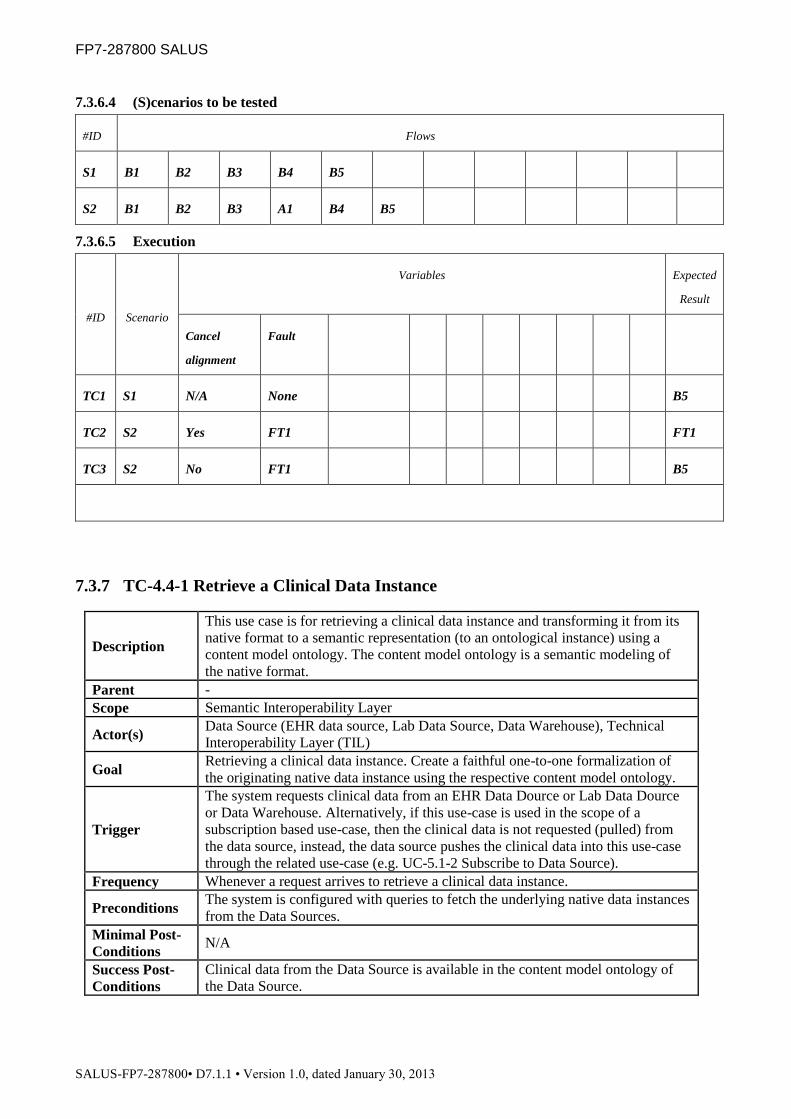
FP7-287800 SALUS
SALUS-FP7-287800• D7.1.1 • Version 1.0, dated January 30, 2013
7.3.6.4 (S)cenarios to be tested
#ID Flows
S1 B1 B2 B3 B4 B5
S2 B1 B2 B3 A1 B4 B5
7.3.6.5 Execution
#ID Scenario
Variables Expected
Result
Cancel
alignment
Fault
TC1 S1 N/A None B5
TC2 S2 Yes FT1 FT1
TC3 S2 No FT1 B5
7.3.7 TC-4.4-1 Retrieve a Clinical Data Instance
Description
This use case is for retrieving a clinical data instance and transforming it from its
native format to a semantic representation (to an ontological instance) using a
content model ontology. The content model ontology is a semantic modeling of
the native format.
Parent -
Scope Semantic Interoperability Layer
Actor(s) Data Source (EHR data source, Lab Data Source, Data Warehouse), Technical
Interoperability Layer (TIL)
Goal Retrieving a clinical data instance. Create a faithful one-to-one formalization of
the originating native data instance using the respective content model ontology.
Trigger
The system requests clinical data from an EHR Data Dource or Lab Data Dource
or Data Warehouse. Alternatively, if this use-case is used in the scope of a
subscription based use-case, then the clinical data is not requested (pulled) from
the data source, instead, the data source pushes the clinical data into this use-case
through the related use-case (e.g. UC-5.1-2 Subscribe to Data Source).
Frequency Whenever a request arrives to retrieve a clinical data instance.
Preconditions The system is configured with queries to fetch the underlying native data instances
from the Data Sources.
Minimal Post-
Conditions N/A
Success Post-
Conditions
Clinical data from the Data Source is available in the content model ontology of
the Data Source.

FP7-287800 SALUS
SALUS-FP7-287800• D7.1.1 • Version 1.0, dated January 30, 2013
7.3.7.1 Use-Case (B)asic flows
#ID Description
B1 The Query is translated to the native query format of the Data Source by invoking the “UC-4.4-8 Export
Query” use case
B2 The system makes a connection to the Data Source. The system sends a request for data to the data source in
the native query format of the data source.
B3 Based on the type of the data source, data source can be connected by invoking the “UC-5.2-2 Query Data
Source” Use case (supported through Technical Interoperability Layer).
B4 The data source returns requested clinical data in the native format of the Data Source.
B5 The system converts the clinical data to a semantic representation using the data sources respective content
model ontology.
7.3.7.2 Use-Case (A)lternative flows
#ID Description
N/A
7.3.7.3 Fault Cases
These will be used for executing the test scenarios for fault tolerance test:
#ID Fault Fault Tolerance Requirement Description
FT1 Native query unavailable The Query can not be translated to the native query format
The system returns an error message stating that the Query can not
be translated to the native query format.
FT2 Data Source unavailable The Data Source is not available for executing the query on.
The system returns an error message stating that the Data Source is
not available for executing the query on.
FT3 Content model ontology unavailable The content model ontology of the data source is not available.
The system returns an error message stating that the content model
ontology of the data source is not available.

FP7-287800 SALUS
SALUS-FP7-287800• D7.1.1 • Version 1.0, dated January 30, 2013
7.3.7.4 (S)cenarios to be tested
#ID Flows
S1 B1 B2 B4 B5
S2 B1 B2 B3 B4 B5
7.3.7.5 Execution
#ID Scenario
Variables Expected
Result
Fault
TC1 S1 None B5
TC2 S1 FT1 FT1
TC3 S1 FT2 FT2
TC4 S1 FT3 FT3
TC5 S2 None B5
TC6 S2 FT1 FT1
TC7 S2 FT2 FT2
TC8 S2 FT3 FT3
7.3.8 TC-4.4-2 Convert to SALUS Semantic Data Representation
Description This use case retrieves a clinical data instance and creates a semantic model from
it, represented in the SALUS Core ontology.
Parent -
Scope Semantic Interoperability Layer
Actor(s) -
Goal The clinical data is represented in the SALUS core ontology.
Trigger
The system requests clinical data from a Data Source (EHR data source or lab data
source or Data warehouse). Called during the execution of “UC-4.4-6 Query a
SALUS Semantic Data Representation” use case
Frequency Whenever a request arrives
Preconditions
The system is configured with mapping rules which map the source content model
ontology to the SALUS core ontology.
(Optional) The system is configured with terminology mappings from the
reference terminologies used by the data source to the SALUS core ontology.
Minimal Post- N/A

FP7-287800 SALUS
SALUS-FP7-287800• D7.1.1 • Version 1.0, dated January 30, 2013
Conditions
Success Post-
Conditions
The clinical data instance is transformed to the SALUS core ontology and is made
available in the system.
7.3.8.1 Use-Case (B)asic flows
#ID Description
B1 The system retrieves the clinical data instances by invoking use case “UC-4.4-1 Retrieve a Clinical Data
Instance”
B2 The system uses the mapping rules to align the clinical data instance with the SALUS core ontology.
B3 (Optional) The system uses the terminology mapping rules to map coded data values to SALUS core ontology
instances.
B4 The semantic model generated in previous steps is available in the system.
7.3.8.2 Use-Case (A)lternative flows
#ID Description
N/A
7.3.8.3 Fault Cases
These will be used for executing the test scenarios for fault tolerance test:
#ID Fault Fault Tolerance Requirement Description
FT1 Concept mapping unavailable The ontology mapping from the local content model to the SALUS
core ontology is unavailable.
The system returns an error message stating that the mapping from
the local content model to the SALUS core ontology is unavailable.
FT2 Terminology mapping unavailable The terminology mapping from the local terminology system to the
SALUS core ontology is unavailable.
The system returns an error message stating that the mapping from
the local terminology system tot the SALUS core ontology is
unavailable.
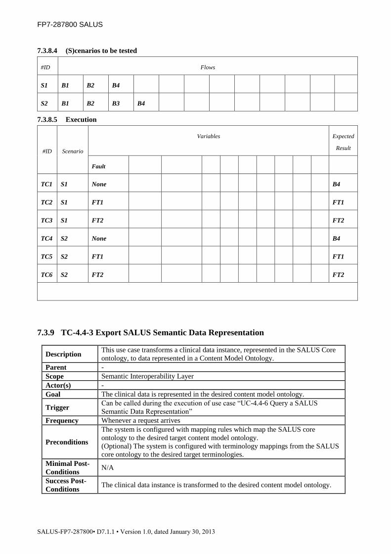
FP7-287800 SALUS
SALUS-FP7-287800• D7.1.1 • Version 1.0, dated January 30, 2013
7.3.8.4 (S)cenarios to be tested
#ID Flows
S1 B1 B2 B4
S2 B1 B2 B3 B4
7.3.8.5 Execution
#ID Scenario
Variables Expected
Result
Fault
TC1 S1 None B4
TC2 S1 FT1 FT1
TC3 S1 FT2 FT2
TC4 S2 None B4
TC5 S2 FT1 FT1
TC6 S2 FT2 FT2
7.3.9 TC-4.4-3 Export SALUS Semantic Data Representation
Description This use case transforms a clinical data instance, represented in the SALUS Core
ontology, to data represented in a Content Model Ontology.
Parent -
Scope Semantic Interoperability Layer
Actor(s) -
Goal The clinical data is represented in the desired content model ontology.
Trigger Can be called during the execution of use case “UC-4.4-6 Query a SALUS
Semantic Data Representation”
Frequency Whenever a request arrives
Preconditions
The system is configured with mapping rules which map the SALUS core
ontology to the desired target content model ontology.
(Optional) The system is configured with terminology mappings from the SALUS
core ontology to the desired target terminologies.
Minimal Post-
Conditions N/A
Success Post-
Conditions The clinical data instance is transformed to the desired content model ontology.

FP7-287800 SALUS
SALUS-FP7-287800• D7.1.1 • Version 1.0, dated January 30, 2013
7.3.9.1 Use-Case (B)asic flows
#ID Description
B1 The input of this use case is a clinical data instance in the SALUS core ontology and the desired target
content model ontology.
B2 The system uses the mapping rules to align the clinical data instance with the desired target content model
ontology.
B3 (Optional) The system uses the terminology mapping rules to map clinical data instances to the desired
terminology code values.
7.3.9.2 Use-Case (A)lternative flows
#ID Description
N/A
7.3.9.3 Fault Cases
These will be used for executing the test scenarios for fault tolerance test:
#ID Fault Fault Tolerance Requirement Description
FT1 Concept mapping unavailable The ontology mapping from the SALUS core ontology to the target
content model is unavailable.
The system returns an error message stating that the mapping from
the SALUS core ontology to the target content model is unavailable.
FT2 Terminology mapping unavailable The terminology mapping from the SALUS core ontology to the
target content terminology is unavailable.
The system returns an error message stating that the mapping from
the SALUS core ontology to the target content terminology is
unavailable.

FP7-287800 SALUS
SALUS-FP7-287800• D7.1.1 • Version 1.0, dated January 30, 2013
7.3.9.4 (S)cenarios to be tested
#ID Flows
S1 B1 B2
S2 B1 B2 B3
7.3.9.5 Execution
#ID Scenario
Variables Expected
Result
Fault
TC1 S1 None B2
TC2 S1 FT1 FT1
TC3 S1 FT2 FT2
TC4 S2 None B3
TC5 S2 FT1 FT1
TC6 S2 FT2 FT2
7.3.10 TC-4.4-4 Export a Clinical Data Instance
Description This use case transforms a data instance from its content model ontology to its
respective native format.
Parent
Scope Semantic Interoperability Layer
Actor(s)
Goal Extract data from a data instance in a content model ontology and construct a data
instance from it in its native format.
Trigger Can be called during the execution of use case “UC-4.4-6 Query a SALUS
Semantic Data Representation”.
Frequency
Preconditions
The system is configured with the native format content template and either with
a. semantic queries to extract the required data elements from the content
model representation.
b. a mapping definition between the content ontology and content template
representing the native format (de-normalization approach)
Minimal Post-
Conditions N/A
Success Post-
Conditions The clinical data is represented in the respective native format.
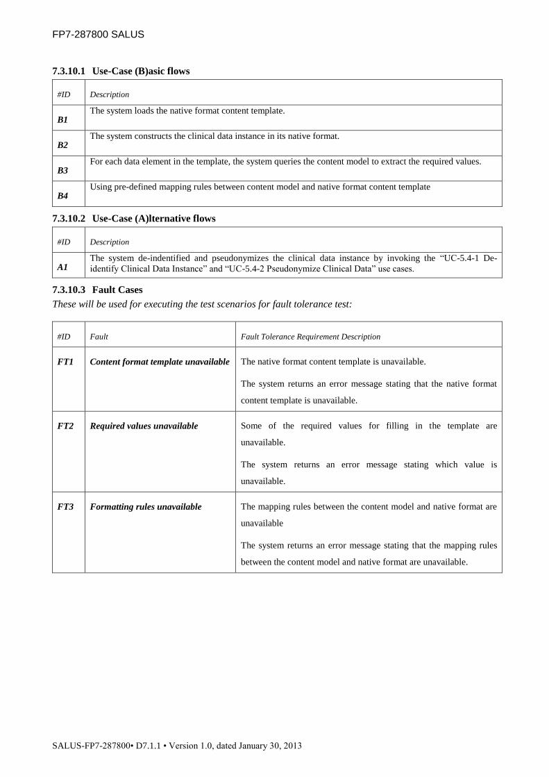
FP7-287800 SALUS
SALUS-FP7-287800• D7.1.1 • Version 1.0, dated January 30, 2013
7.3.10.1 Use-Case (B)asic flows
#ID Description
B1 The system loads the native format content template.
B2 The system constructs the clinical data instance in its native format.
B3 For each data element in the template, the system queries the content model to extract the required values.
B4 Using pre-defined mapping rules between content model and native format content template
7.3.10.2 Use-Case (A)lternative flows
#ID Description
A1 The system de-indentified and pseudonymizes the clinical data instance by invoking the “UC-5.4-1 De-
identify Clinical Data Instance” and “UC-5.4-2 Pseudonymize Clinical Data” use cases.
7.3.10.3 Fault Cases
These will be used for executing the test scenarios for fault tolerance test:
#ID Fault Fault Tolerance Requirement Description
FT1 Content format template unavailable The native format content template is unavailable.
The system returns an error message stating that the native format
content template is unavailable.
FT2 Required values unavailable Some of the required values for filling in the template are
unavailable.
The system returns an error message stating which value is
unavailable.
FT3 Formatting rules unavailable The mapping rules between the content model and native format are
unavailable
The system returns an error message stating that the mapping rules
between the content model and native format are unavailable.

FP7-287800 SALUS
SALUS-FP7-287800• D7.1.1 • Version 1.0, dated January 30, 2013
7.3.10.4 (S)cenarios to be tested
#ID Flows
S1 B1 B2 B3
S2 B1 B2 B4
S3 B1 B2 A1 B3
S4 B1 B2 A1 B4
7.3.10.5 Execution
#ID Scenario
Variables Expected
Result
Fault
TC1 S1 None B3
TC2 S1 FT1 FT1
TC3 S1 FT2 FT2
TC4 S1 FT3 FT3
TC5 S2 None B4
TC6 S2 FT1 FT1
TC7 S2 FT2 FT2
TC8 S2 FT3 FT3
TC9 S3 None B3
TC10 S3 FT1 FT1
TC11 S3 FT2 FT2
TC12 S3 FT3 FT3
TC13 S4 None B4
TC14 S4 FT1 FT1
TC15 S4 FT2 FT2
TC16 S4 FT3 FT3

FP7-287800 SALUS
SALUS-FP7-287800• D7.1.1 • Version 1.0, dated January 30, 2013
7.3.11 TC-4.4-5 Query in SIL
Description This use case facilitates querying one or more data source over SALUS
Interoperability Layer.
Parent
Scope Semantic Interoperability Layer
Actor(s) Any SALUS System Actor (such as Technical Interoperability Layer, ICSR
Reporting Tool)
Goal Select, combine and project clinical data from one or more semantic models.
Trigger The system wants to execute a query on Data Sources through Semantic
Interoperability Layer
Frequency
Preconditions N/A
Minimal Post-
Conditions N/A
Success Post-
Conditions The system successfully returns the requested data.
7.3.11.1 Use-Case (B)asic flows
#ID Description
B1 If the query is forwarded through “UC-5.2-1 Query SIL through TIL” use case, the query in native format is
mapped to SALUS semantic data representation format by invoking the “UC-4.4-7 Translate Query to
SALUS Semantic Data Representation” use case
B2 Query is executed by invoking the “UC-4.4-6 Query a SALUS Semantic Data Representation” use case.
7.3.11.2 Use-Case (A)lternative flows
#ID Description
N/A
7.3.11.3 Fault Cases
These will be used for executing the test scenarios for fault tolerance test:
#ID Fault Fault Tolerance Requirement Description
N/A

FP7-287800 SALUS
SALUS-FP7-287800• D7.1.1 • Version 1.0, dated January 30, 2013
7.3.11.4 (S)cenarios to be tested
#ID Flows
S1 B1 B2
S2 B2
7.3.11.5 Execution
#ID Scenario
Variables Expected
Result
TC1 S1 B2
TC2 S2 B2
7.3.12 TC-4.4-6 Query a SALUS Semantic Data Representation
Description This use case performs a semantic query on one or more SALUS semantic data
representations.
Parent UC-4.4-5 Query in SIL
Scope Semantic Interoperability Layer
Actor(s)
Goal Select, combine and project clinical data from one or more semantic models.
Trigger The system wants to execute a semantic query on SALUS data representations
Frequency
Preconditions N/A
Minimal Post-
Conditions N/A
Success Post-
Conditions The system successfully returns the requested data.
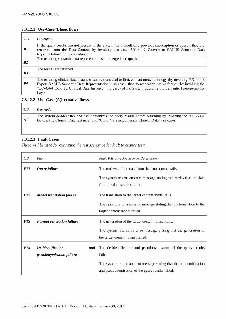
FP7-287800 SALUS
SALUS-FP7-287800• D7.1.1 • Version 1.0, dated January 30, 2013
7.3.12.1 Use-Case (B)asic flows
#ID Description
B1 If the query results are not present in the system (as a result of a previous subscription or query), they are
retrieved from the Data Sources by invoking use case “UC-4.4-2 Convert to SALUS Semantic Data
Representation” for each instance.
B2 The resulting semantic data representations are merged and queried.
B3 The results are returned
B4 The resulting clinical data instances can be translated to first, content model ontology (by invoking “UC-4.4-3
Export SALUS Semantic Data Representation” use case), then to respective native format (by invoking the
“UC-4.4-4 Export a Clinical Data Instance” use case) of the System querying the Semantic Interoperability
Layer
7.3.12.2 Use-Case (A)lternative flows
#ID Description
A1 The system de-identifies and pseudonymizes the query results before returning by invoking the “UC-5.4-1
De-identify Clinical Data Instance” and “UC-5.4-2 Pseudonymize Clinical Data” use cases
7.3.12.3 Fault Cases
These will be used for executing the test scenarios for fault tolerance test:
#ID Fault Fault Tolerance Requirement Description
FT1 Query failure The retrieval of the data from the data sources fails.
The system returns an error message stating that retrieval of the data
from the data sources failed.
FT2 Model translation failure The translation to the target content model fails.
The system returns an error message stating that the translation to the
target content model failed.
FT3 Format generation failure The generation of the target content format fails.
The system returns an error message stating that the generation of
the target content format failed.
FT4 De-identification and
pseudonymisation failure
The de-identification and pseudonymisation of the query results
fails.
The system returns an error message stating that the de-identification
and pseudonomisation of the query results failed.

FP7-287800 SALUS
SALUS-FP7-287800• D7.1.1 • Version 1.0, dated January 30, 2013
7.3.12.4 (S)cenarios to be tested
#ID Flows
S1 B1 B2 B3
S2 B1 B2 B3 B4
S3 B1 B2 B3 A1
S4 B1 B2 B3 A1 B4
7.3.12.5 Execution
#ID Scenario
Variables Expected
Result
Fault
TC1 S1 None B3
TC2 S1 FT1 FT1
TC3 S2 None B4
TC4 S2 FT1 FT1
TC5 S2 FT2 FT2
TC6 S2 FT3 FT3
TC7 S3 None A1
TC8 S3 FT1 FT1
TC9 S3 FT4 FT4
TC10 S4 None B4
TC11 S4 FT1 FT1
TC12 S4 FT2 FT2
TC13 S4 FT3 FT3
TC14 S4 FT4 FT4

FP7-287800 SALUS
SALUS-FP7-287800• D7.1.1 • Version 1.0, dated January 30, 2013
7.3.13 TC-4.4-7 Translate Query to SALUS Semantic Data Representation
Description This use case transforms a query represented in native format of the querying
system to a semantic query on SALUS semantic data representation.
Parent
Scope Semantic Interoperability Layer
Actor(s)
Goal The query is represented as a semantic query on SALUS semantic data
representation
Trigger
The querying system wants to execute a query on SALUS data representations by
invoking the “UC-5.2-1 Query SIL through TIL” use case which includes “UC-
4.4-5 Query in SIL” use case
Frequency
Preconditions
The system is configured with mapping rules which map the query in native
format to the corresponding content model ontology.
The system is configured with mapping rules which map the query in content
model ontology to SALUS core ontology.
(Optional) The system is configured with terminology mappings from the SALUS
core ontology to the desired target terminologies.
Minimal Post-
Conditions N/A
Success Post-
Conditions The query is transformed into a semantic query on top of SALUS core ontology.
7.3.13.1 Use-Case (B)asic flows
#ID Description
B1 The input is the query represented in native format of the querying system
B2 First the system uses the mapping rules to align the query represented in native format with the desired
content model ontology
B3 Then, the system uses the mapping rules to align the query in the content model ontology with the SALUS
core ontology
B4 The system uses the terminology mapping rules to map coded data values to SALUS core ontology instances.
7.3.13.2 Use-Case (A)lternative flows
#ID Description
N/A
7.3.13.3 Fault Cases
These will be used for executing the test scenarios for fault tolerance test:

FP7-287800 SALUS
SALUS-FP7-287800• D7.1.1 • Version 1.0, dated January 30, 2013
#ID Fault Fault Tolerance Requirement Description
FT1 Unsupported query The native format query is not supported.
The system returns an error message stating that the native format
query is not supported by the system.
FT2 Terminology mapping unavailable The mapping of a terminology code to the SALUS core ontology
concept is unavailable.
The system returns an error message stating that the mapping of a
terminology code to the SALUS core ontology concept is not
available.
7.3.13.4 (S)cenarios to be tested
#ID Flows
S1 B1 B2 B3
S2 B1 B2 B3 B4
7.3.13.5 Execution
#ID Scenario
Variables Expected
Result
Fault
TC1 S1 None B3
TC2 S1 FT1 FT1
TC3 S2 None B4
TC4 S2 FT1 FT1
TC5 S2 FT2 FT2
7.3.14 TC-4.4-8 Export Query
Description
This use case transforms the query represented in the SALUS core ontology to the
native query representation format accepted by the Data Source (EHR Data Source
or Lab Data Source or Data warehouse).
Parent
Scope Semantic Interoperability Layer
Actor(s)
Goal The query is represented in the native format accepted by the data source
Trigger Can be called during the execution of “UC-4.4-1 Retrieve a Clinical Data
Instance” use case
Frequency
Preconditions The system is configured with the native format content template to represent the

FP7-287800 SALUS
SALUS-FP7-287800• D7.1.1 • Version 1.0, dated January 30, 2013
query.
The system is configured with mapping rules which map the SALUS core
ontology to the corresponding target content model ontology.
The system is configured with terminology mappings from the SALUS core
ontology to the desired target terminologies.
The system is configured with mapping rules between the content model ontology
and the native query format (content template representation).
Minimal Post-
Conditions N/A
Success Post-
Conditions The query is transformed into native format accepted by the Data Source.
7.3.14.1 Use-Case (B)asic flows
#ID Description
B1 The system uses the mapping rules to align the query represented in SALUS core ontology with the
corresponding content model ontology of the Data Source.
B2 The system uses the terminology mapping rules to map the query to the desired terminology code values.
B3 The system uses the mapping rules to align the query represented in content model ontology of the Data
Source to the native query format (content template representation)
7.3.14.2 Use-Case (A)lternative flows
#ID Description
N/A
7.3.14.3 Fault Cases
These will be used for executing the test scenarios for fault tolerance test:
#ID Fault Fault Tolerance Requirement Description
N/A
7.3.14.4 (S)cenarios to be tested
#ID Flows
S1 B1 B2 B3
7.3.14.5 Execution
#ID Scenario
Variables Expected
Result
TC1 S1 B3

FP7-287800 SALUS
SALUS-FP7-287800• D7.1.1 • Version 1.0, dated January 30, 2013
7.3.15 TC-4.4-9 Subscribe to SALUS SIL
Description
This use case facilitates subscribing one or more data source over SALUS
Interoperability Layer. This is a specialization of Use case “UC-4.4-5 Query in
SIL” where, in the scope of the included use case “UC-4.4-6 Query a SALUS
Semantic Data Representation”, the clinical data is not queried synchronously,
instead the clinical data instances are asynchronously collected by “UC-4.4-1
Retrieve a Clinical Data Instance” use case, and converted to SALUS semantic
data representation and if necessary to the native data representation format of the
subscribing System (UC-4.4-2 Convert to SALUS Semantic Data Representation,
UC-4.4-3 Export SALUS Semantic Data Representation and UC-4.4-4 Export a
Clinical Data Instance).
Parent UC-4.4-5 Query in SIL
Scope Semantic Interoperability Layer
Actor(s) Any SALUS System Actor (such as Technical Interoperability Layer, ADE
Notification Tool)
Goal Subscribe, collect, combine and project clinical data from one or more semantic
models.
Trigger The system wants to execute a subscription query on SALUS data representations
Frequency
Preconditions SALUS Semantic Data Representation available
Minimal Post-
Conditions
Success Post-
Conditions Subscription to a SALUS Semantic Data Representation available.
7.3.15.1 Use-Case (B)asic flows
#ID Description
B1 A relevant SALUS Semantic Data Representation is selected
B2 A subscription is registered for the SALUS Semantic Data Representation
7.3.15.2 Use-Case (A)lternative flows
#ID Description
N/A
7.3.15.3 Fault Cases
These will be used for executing the test scenarios for fault tolerance test:
#ID Fault Fault Tolerance Requirement Description
FT1 SALUS representation unavailable The SALUS Semantic Data Representation is not available.
Registration cannot be done.
The system returns an error message stating that the SALUS
Semantic Data Representation is not available.
FT2 Subscription registration error The subscription cannot be registered.
The system returns an error message stating that the subscription
cannot be registered.

FP7-287800 SALUS
SALUS-FP7-287800• D7.1.1 • Version 1.0, dated January 30, 2013
7.3.15.4 (S)cenarios to be tested
#ID Flows
S1 B1 B2
7.3.15.5 Execution
#ID Scenario
Variables Expected
Result
Fault
TC1 S1 None B2
TC2 S1 FT1 FT1
TC3 S1 FT2 FT2
7.3.16 TC-4.4-10 Cancel Subscription to SALUS SIL
Description
This use-case cancels an already existing subscription over SALUS Semantic
Interoperability Layer. Since cancellation does not require a query over SIL or
associated Data Sources, only internal machinery of SIL is adjusted according to
reflect the cancellation of the specified subscription.
Parent
Scope Semantic Interoperability Layer
Actor(s) Any SALUS System Actor (such as Technical Interoperability Layer, ADE
Notification Tool), Technical Interoperability Layer (TIL)
Goal Cancel an already existing subscription over SALUS Semantic Interoperability
Layer
Trigger The system wants to cancel an existing subscription on SALUS data
representations
Frequency
Preconditions Subscription to SALUS Semantic Data Representation available
Minimal Post-
Conditions
Success Post-
Conditions Subscription to a SALUS Semantic Data Representation removed.

FP7-287800 SALUS
SALUS-FP7-287800• D7.1.1 • Version 1.0, dated January 30, 2013
7.3.16.1 Use-Case (B)asic flows
#ID Description
B1 The relevant subscription to a SALUS Semantic Data Representation is selected
B2 The subscription is cancelled.
7.3.16.2 Use-Case (A)lternative flows
#ID Description
N/A
7.3.16.3 Fault Cases
These will be used for executing the test scenarios for fault tolerance test:
#ID Fault Fault Tolerance Requirement Description
FT1 Subscription registration
unavailable
The registration of the subscription is unavailable.
The system returns an error message stating that the subscription is
not available.
FT2 Subscription removal error The registration of the subscription can not be removed.
The system returns an error message stating that the subscription can
not be removed.
7.3.16.4 (S)cenarios to be tested
#ID Flows
S1 B1 B2
7.3.16.5 Execution
#ID Scenario
Variables Expected
Result
Fault
TC1 S1 None B2
TC1 S1 FT1 FT1
TC1 S1 FT2 FT2
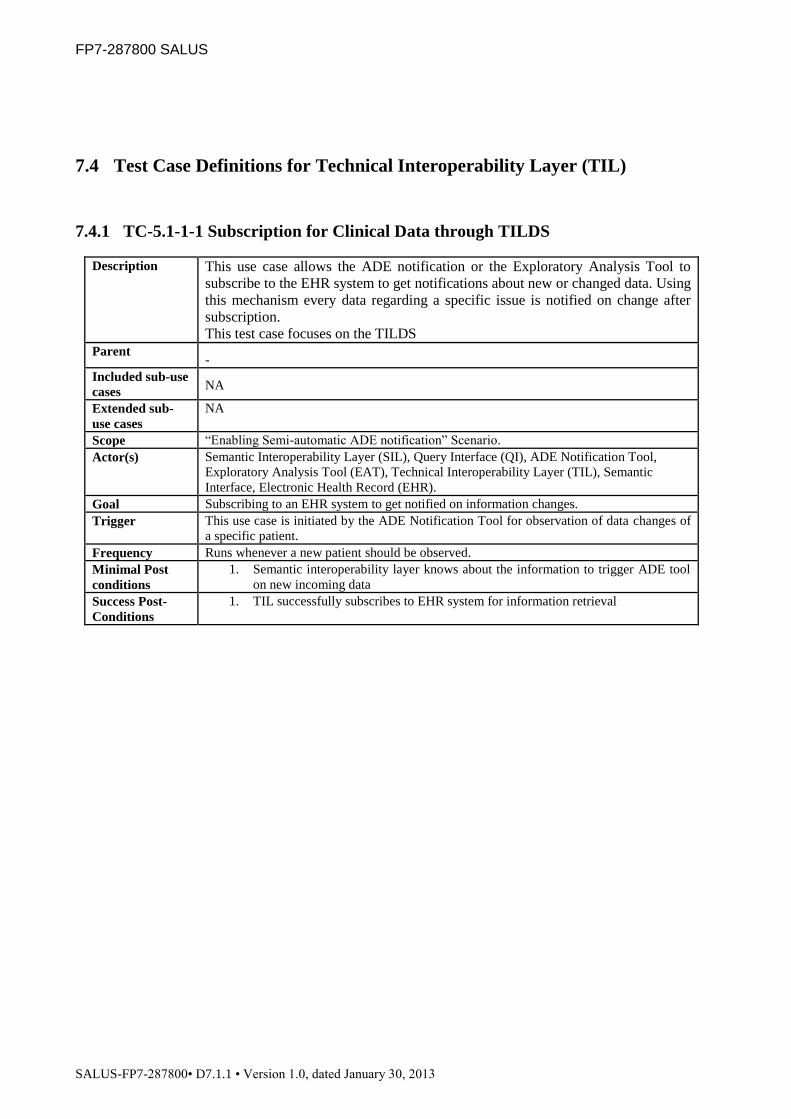
FP7-287800 SALUS
SALUS-FP7-287800• D7.1.1 • Version 1.0, dated January 30, 2013
7.4 Test Case Definitions for Technical Interoperability Layer (TIL)
7.4.1 TC-5.1-1-1 Subscription for Clinical Data through TILDS
Description This use case allows the ADE notification or the Exploratory Analysis Tool to
subscribe to the EHR system to get notifications about new or changed data. Using
this mechanism every data regarding a specific issue is notified on change after
subscription.
This test case focuses on the TILDS
Parent -
Included sub-use
cases NA
Extended sub-
use cases
NA
Scope “Enabling Semi-automatic ADE notification” Scenario.
Actor(s) Semantic Interoperability Layer (SIL), Query Interface (QI), ADE Notification Tool,
Exploratory Analysis Tool (EAT), Technical Interoperability Layer (TIL), Semantic
Interface, Electronic Health Record (EHR).
Goal Subscribing to an EHR system to get notified on information changes.
Trigger This use case is initiated by the ADE Notification Tool for observation of data changes of
a specific patient.
Frequency Runs whenever a new patient should be observed.
Minimal Post
conditions
1. Semantic interoperability layer knows about the information to trigger ADE tool
on new incoming data
Success Post-
Conditions
1. TIL successfully subscribes to EHR system for information retrieval

FP7-287800 SALUS
SALUS-FP7-287800• D7.1.1 • Version 1.0, dated January 30, 2013
7.4.1.1 Use-Case (B)asic flows
#ID Description
B1 ADE notification or Exploratory Analysis Tool initiates a subscription through the Query
Interface (QI) for retrieving new or changed data of a specific patient
B2 TILDS extracts the payload carrying the medical data and hands it over to SIL
B3 SIL checks the input and informs TILDS about the content being understood well by SIL and hands the
information bottom down to the next recipient within the workflow
B4 TILDS waits for response. ADE Notification Tool or Exploratory Analysis Tool is in blocking mode until
SIL returned
B5 ADE notification or Exploratory Analysis Tool returned successful in subscription notified by TILDS
7.4.1.2 Use-Case (A)lternative flows
#ID Description
A1 SIL returns directly to TILDS as it does not understand the content of the payload
A2 TILDS waits for response. ADE Notification Tool or Exploratory Analysis Tool is in blocking mode until
SIL returned in this case none successful due to an issue related to EHR/RDF service, TIDSQS or a semantic
based subscription.
7.4.1.3 Fault Cases
These will be used for executing the test scenarios for fault tolerance test:

FP7-287800 SALUS
SALUS-FP7-287800• D7.1.1 • Version 1.0, dated January 30, 2013
#ID Fault Fault Tolerance Requirement Description
FT1 Incorrect payload The payload defined for subscription at the SALUS core system
cannot be understood by SIL for some reason. A reason may be for
example a not supported query template. SIL will notify the
subscribing party through TILDS about the problem. This should be
handled by IHE CM extension. If possible standard messages should
be used.
FT2 Subscription issue in TIDSQS or
SIL
The subscription to be sent through SIL or TIDSQS failed for some
reason. This can be for example a missing network connection or
also a template issue at a lower layer. As soon as SIL is notified
about the problem it will notify the subscribing party through TILDS
about the problem. This should be handled by IHE CM extension. If
possible standard messages should be used.
7.4.1.4 (S)cenarios to be tested
#ID Flows
S1 B1 B2 B3 B4 B5
S2 B1 B2 A1
S3 B1 B2 B3 B4 A2
7.4.1.5 Execution (Functionality and Fault Tolerance Tests)
#ID Scenario
Variables Expected
Result
Content Model Type Fault
TC1 S1 IHE CM standard
subscription
None B5
TC2 S1 IHE CM by EN13606
subscription
None B5
TC3 S2 IHE CM by invalid
subscription
FT1 A1
TC4 S3 IHE CM standard
subscription
FT2 A2

FP7-287800 SALUS
SALUS-FP7-287800• D7.1.1 • Version 1.0, dated January 30, 2013
7.4.2 TC-5.1-1-2 Subscribe to Data Source through TILDSQS
Description This use case allows the ADE notification or the Exploratory Analysis Tool to
subscribe to the EHR system to get notifications about new or changed data. Using
this mechanism every data regarding a specific issue is notified on change after
subscription.
This test case focuses on the TILDSQS.
Parent -
Included sub-use
cases NA
Extended sub-
use cases
NA
Scope “Enabling Semi-automatic ADE notification” Scenario.
Actor(s) Semantic Interoperability Layer (SIL), Query Interface (QI), ADE Notification Tool,
Exploratory Analysis Tool (EAT), Technical Interoperability Layer (TIL), Semantic
Interface, Electronic Health Record (EHR).
Goal Subscribing to an EHR system to get notified on information changes.
Trigger This use case is initiated by the ADE Notification Tool for observation of data
changes of a specific patient.
Frequency Runs whenever a new patient should be observed.
Minimal Post
conditions
1. Semantic interoperability layer knows about the information to trigger ADE tool
on new incoming data
Success Post-
Conditions
1. TIL successfully subscribes to EHR system for information retrieval
7.4.2.1 Use-Case (B)asic flows
#ID Description
B1 EHR RDF service initiates a subscription through the Query Interface (QI) for retrieving new or changed data
of a specific patient
B2 TIQSDS extracts the payload carrying the medical data and initiates communication of IHE CM to the EHR
B3 TIDSQS sends the subscription payload by using IHE CM extension to the EHR system
B4 TIDSQS successfully subscribes to the EHR and sends the result back to EHR RDF service
7.4.2.2 Use-Case (A)lternative flows
#ID Description
A1 The EHR system is not available due to a network issue. Therefore the communication cannot be
established and no subscription can be made. This will lead to an incomplete subscription and will
be notified to the EHR RDF service
A2 The subscription template send to the EHR cannot be understand by the EHR system and leads to an
exception which will result in an incomplete subscription notified to the EHR RDF service
7.4.2.3 Fault Cases
These will be used for executing the test scenarios for fault tolerance test:

FP7-287800 SALUS
SALUS-FP7-287800• D7.1.1 • Version 1.0, dated January 30, 2013
#ID Fault Fault Tolerance Requirement Description
FT1 Incorrect payload The payload defined for subscription at the SALUS core system
cannot be understood by the EHR system for some reason. A reason
may be for example a none supported query template. The result of
the incorrect payload should be a standard based IHE CM extension
message informing TIDSQS about the problem. TIDSQS will inform
SIL about the situation. If SIL is able to switch the content model
this will be done and retried, otherwise SIL will inform the querying
party about the situation through TILDS
FT2 Subscription issue in TIDSQS due
to network problems
The subscription to be sent through TIDSQS failed for some reason.
This can be for example a missing network connection. TIDSQS will
inform SIL which will cause an IHE CM extension error handling in
TILDS. For the querying party it should look as if the error occurred
directly at TILDS. The fault handling from there will be the same as
if the error was noticed already at TILDS.
7.4.2.4 (S)cenarios to be tested
#ID Flows
S1 B1 B2 B3 B4
S2 B1 B2 A1
S3 B1 B2 B3 A2
7.4.2.5 Execution (Functionality and Fault Tolerance Tests)
#ID Scenario
Variables Expected
Result
Content Model Type Fault
TC1 S1 IHE CM standard
subscription
None B4
TC2 S1 IHE CM by EN13606
subscription
None B4
TC3 S2 IHE CM by invalid
subscription
FT2 A1
TC4 S3 IHE CM standard
subscription
FT1 A2

FP7-287800 SALUS
SALUS-FP7-287800• D7.1.1 • Version 1.0, dated January 30, 2013
7.4.3 TC-5.1-2-1 Retrieving clinical data through TILDS on subscription based query
Description This use case allows the ADE notification or Exploratory Analysis Tool to retrieve
This use case allows the ADE notification or Exploratory Analysis Tool to retrieve
data out of the EHR system after a successful subscription to the data of interest.
ADE notification and Exploratory Analysis Tool are described in this use case
together as a SALUS service, as they are performing the same actions. This will
keep the graphic a bit simpler.
This TC focuses on TILDS
Parent -
Included sub-use
cases UC-5.1-1 Subscription for clinical data
Extended sub-
use cases NA
Scope “Enabling Semi-automatic ADE notification” Scenario.
Actor(s) Semantic Interoperability Layer (SIL), Query Interface (QI), ADE Notification
Tool, Exploratory Analysis Tool, Technical Interoperability Layer (TIL),
Semantic Interface, Electronic Health Record (EHR)
Goal Retrieving data out of an EHR system on information changes.
Trigger This use case is initiated by the underlying EHR system on new incoming
information.
Frequency Runs whenever a new patient should be observed and data has changed.
Minimal Post
conditions ADE notification or Exploratory Analysis Tool retrieved information through QI
and waits for new triggers
Success Post-
Conditions ADE notification or Exploratory Analysis Tool retrieves all information needed
7.4.3.1 Use-Case (B)asic flows
#ID Description
B1 SIL gets some subscription related data for the ADE notification or Exploratory Analysis Tool. It translates
the data to the final content model of the tool and forwards it as a payload to TILDS
B2 TILDS looks up the service which made the subscription
B3 TILDS sends the data using IHE CM extension to the ADE notification or Exploratory Analysis Tool
7.4.3.2 Use-Case (A)lternative flows
#ID Description
A1 TILDS looks up the service which made the subscription and could not find the related service (This may be
due to the problem that the subscription was made semantically and not using TILDS)
A2 TILDS tries to send the data to the corresponding tool, but could not reach it.
A3 TILDS tries to send the data to the corresponding tool, but the communication failed due to an issue of the
payload. Maybe an incorrect content model was used.
7.4.3.3 Fault Cases
These will be used for executing the test scenarios for fault tolerance test:

FP7-287800 SALUS
SALUS-FP7-287800• D7.1.1 • Version 1.0, dated January 30, 2013
#ID Fault Fault Tolerance Requirement Description
FT1 TILDS cannot find the
corresponding sink to send the data
to
Maybe TILDS will be asked for returning data to a subscribed
sink and does not have a receiver registered in the lookup
table. This might happen within the timeslot where an update
message is in translation process and the sink has in parallel
send a cancel request for the subscription. In this case the
update message will be deleted.
FT2 Network connection is missing If the network connection was interrupted it will be retried for some
time, but stopped afterwards
FT3 Usage of wrong local content model
for the subscribed sink
For some reason it might happen that the sink will not support
the content model of the received data. This cannot be handled
as the content model which can be understood in this case
must be unknown
7.4.3.4 (S)cenarios to be tested
#ID Flows
S1 B1 B2 B3 B4
S2 B1 A1
S3 B1 B2 A2
S4 B1 B2 A3
7.4.3.5 Execution (Functionality and Fault Tolerance Tests)
#ID Scenario
Variables Expected
Result
Content Model Type Fault
TC1 S1 IHE CM standard
update message
None B4
TC2 S1 IHE CM by EN13606
update message
None B4
TC3 S2 IHE CM invalid update
message
FT1 A1
TC4 S3 IHE CM standard
update message
FT2 A2
TC5 S4 IHE CM standard
update message in CDA
instead of EN13606
FT3 A3

FP7-287800 SALUS
SALUS-FP7-287800• D7.1.1 • Version 1.0, dated January 30, 2013
7.4.4 TC-5.1-2-2 Retrieving data from data source through TILQSDS on subscription
based query
Description This use case allows the ADE notification or Exploratory Analysis Tool to retrieve
This use case allows the ADE notification or Exploratory Analysis Tool to retrieve
data out of the EHR system after a successful subscription to the data of interest.
ADE notification and Exploratory Analysis Tool are described in this use case
together as a SALUS service, as they are performing the same actions. This will
keep the graphic a bit simpler.
This TC focuses on TIDSQS
Parent -
Included sub-use
cases UC-5.1-1 Subscription for clinical data
Extended sub-
use cases NA
Scope “Enabling Semi-automatic ADE notification” Scenario.
Actor(s) Semantic Interoperability Layer (SIL), Query Interface (QI), ADE Notification
Tool,
Exploratory Analysis Tool, Technical Interoperability Layer (TIL), Semantic
Interface, Electronic Health Record (EHR)
Goal Retrieving data out of an EHR system on information changes.
Trigger This use case is initiated by the underlying EHR system on new incoming
information.
Frequency Runs whenever a new patient should be observed and data has changed.
Minimal Post
conditions ADE notification or Exploratory Analysis Tool retrieved information through QI
and waits for new triggers
Success Post-
Conditions ADE notification or Exploratory Analysis Tool retrieves all information needed

FP7-287800 SALUS
SALUS-FP7-287800• D7.1.1 • Version 1.0, dated January 30, 2013
7.4.4.1 Use-Case (B)asic flows
#ID Description
B1 The EHR found some subscription related content and hands it over to the IHE CM system to provide the
data to the SALUS system
B2 The IHE CM extension looks up the subscription and fills the data to a specified template ether in EN13606
or CDA
B3 IHE CM extension sends the data through the extension to the SALUS core system
B4 TIQSDS gets the subscription related data for the ADE notification or Exploratory Analysis Tool. It extracts
the payload from the message and forwards it to the HER RDF service
7.4.4.2 Use-Case (A)lternative flows
#ID Description
A1 IHE CM extension cannot reach SALUS core adapter for IHE CM
A2 SALUS core system cannot translate the message as it does not match the specified SALUS templates
7.4.4.3 Fault Cases
These will be used for executing the test scenarios for fault tolerance test:

FP7-287800 SALUS
SALUS-FP7-287800• D7.1.1 • Version 1.0, dated January 30, 2013
#ID Fault Fault Tolerance Requirement Description
FT1 Network connection is missing If the network connection was interrupted it will be retried for some
time, but stopped afterwards
FT2 Usage of wrong content template For some reason it might happen that the source is using a
message template which is not supported by SALUS core.
This will result in a logged error, but cannot be handled
7.4.4.4 (S)cenarios to be tested
#ID Flows
S1 B1 B2 B3 B4
S2 B1 B2 A1
S3 B1 B2 B3 B4 A2
7.4.4.5 Execution (Functionality and Fault Tolerance Tests)
#ID Scenario
Variables Expected
Result
Content Model Type Fault
TC1 S1 IHE CM standard
update message
None B4
TC2 S1 IHE CM EN13606
update message
None B4
TC3 S2 IHE CM standard
update message
FT1 A1
TC4 S3 IHE CM standard
update message instead
of EN13606
FT2 A2
7.4.5 TC-5.1-3-1 Cancel Subscription for Clinical Data through TILDS
Description This use case allows the ADE notification or Exploratory Analysis Tool to cancel
the subscription to the EHR system for notifications about new or changed data.
Using this mechanism every data transfer from the EHR to the ADE notification
or Exploratory Analysis Tool regarding this subscription is canceled. ADE
notification and Exploratory Analysis Tool are described in this use case together
as a SALUS service, as they are performing the same actions. This will keep the
graphic a bit simpler.

FP7-287800 SALUS
SALUS-FP7-287800• D7.1.1 • Version 1.0, dated January 30, 2013
This test case focuses on the TILDS
Parent -
Included sub-use
cases NA
Extended sub-
use cases
NA
Scope “Enabling Semi-automatic ADE notification” Scenario.
Actor(s) Semantic Interoperability Layer (SIL), Query Interface (QI), ADE Notification Tool,
Exploratory Analysis Tool, Technical Interoperability Layer (TIL), Semantic
Interface, Electronic Health Record (EHR).
Goal Cancel subscription to an EHR system for specific data.
Trigger This use case stops observation of data changes of a specific patient for the ADE
notification or Exploratory Analysis Tool.
Frequency Runs whenever a patient should not be observed anymore for the ADE notification or
Exploratory Analysis Tool.
Minimal Post
conditions
1. TIL is successfully unsubscribed to EHR system and does not retrieve
information anymore.
Success Post-
Conditions
1. TIL is successfully unsubscribed to EHR system and does not retrieve
information anymore.
7.4.5.1 Use-Case (B)asic flows
#ID Description
B1 ADE notification or Exploratory Analysis Tool initiates a cancel subscription through the Query
Interface (QI) for retrieving new or changed data of a specific patient
B2 TILDS extracts the payload carrying the medical data and hands it over to SIL
B3 SIL checks the input and informs TILDS about the content being understood well by SIL and hands the
information bottom down to the next recipient within the workflow
B4 TILDS waits for response. ADE Notification Tool or Exploratory Analysis Tool is in blocking mode until
SIL returned
B5 ADE notification or Exploratory Analysis Tool returned successful in cancel the subscription notified by
TILDS
7.4.5.2 Use-Case (A)lternative flows
#ID Description
A1 SIL returns directly to TILDS as it does not understand the content of the payload
A2 TILDS waits for response. ADE Notification Tool or Exploratory Analysis Tool is in blocking mode until
SIL returned in this case none successful due to an issue related to EHR/RDF service, TIDSQS or a semantic
based subscription.
7.4.5.3 Fault Cases
These will be used for executing the test scenarios for fault tolerance test:

FP7-287800 SALUS
SALUS-FP7-287800• D7.1.1 • Version 1.0, dated January 30, 2013
#ID Fault Fault Tolerance Requirement Description
FT1 Incorrect payload The payload defined for cancel subscription at the SALUS core
system cannot be understood by SIL for some reason. A reason may
be for example a none supported cancel query template. SIL will
notify the cancelling party through TILDS about the problem. This
should be handled by IHE CM extension. If possible standard
messages should be used.
FT2 Subscription issue in TIDSQS or
SIL
The cancel subscription request to be sent through SIL or TIDSQS
failed for some reason. This can be for example a missing network
connection or also a template issue at a lower layer. As soon as SIL
noticed the issue it will notify the subscribing party through TILDS
about it. This should be handled by IHE CM extension. If possible
standard messages should be used.
7.4.5.4 (S)cenarios to be tested
#ID Flows
S1 B1 B2 B3 B4 B5
S2 B1 B2 A1
S3 B1 B2 B3 B4 A2
7.4.5.5 Execution (Functionality and Fault Tolerance Tests)
#ID Scenario
Variables Expected
Result
Content Model Type Fault
TC1 S1 IHE CM standard
cancel subscription
None B5
TC2 S1 IHE CM by EN13606
cancel subscription
None B5
TC3 S2 IHE CM by invalid
cancel subscription
FT1 A1
TC4 S3 IHE CM standard
cancel subscription
FT2 A2
7.4.6 TC-5.1-3-2 Cancel Subscription to Data Source through TIDSQS
Description This use case allows the ADE notification or Exploratory Analysis Tool to cancel
the subscription to the EHR system for notifications about new or changed data.

FP7-287800 SALUS
SALUS-FP7-287800• D7.1.1 • Version 1.0, dated January 30, 2013
Using this mechanism every data transfer from the EHR to the ADE notification
or Exploratory Analysis Tool regarding this subscription is canceled. ADE
notification and Exploratory Analysis Tool are described in this use case together
as a SALUS service, as they are performing the same actions. This will keep the
graphic a bit simpler.
This test case focuses on the TIDSQS
Parent -
Included sub-use
cases NA
Extended sub-
use cases
NA
Scope “Enabling Semi-automatic ADE notification” Scenario.
Actor(s) Semantic Interoperability Layer (SIL), Query Interface (QI), ADE Notification Tool,
Exploratory Analysis Tool, Technical Interoperability Layer (TIL), Semantic
Interface, Electronic Health Record (EHR).
Goal Cancel subscription to an EHR system for specific data.
Trigger This use case stops observation of data changes of a specific patient for the ADE
notification or Exploratory Analysis Tool.
Frequency Runs whenever a patient should not be observed anymore for the ADE notification or
Exploratory Analysis Tool.
Minimal Post
conditions
2. TIL is successfully unsubscribed to EHR system and does not retrieve
information anymore.
Success Post-
Conditions
2. TIL is successfully unsubscribed to EHR system and does not retrieve
information anymore.
7.4.6.1 Use-Case (B)asic flows
#ID Description
B1 EHR RDF service initiates a cancel subscription through the Query Interface (QI) for retrieving new or
changed data of a specific patient
B2 TIQSDS extracts the payload carrying the medical data and initiates communication of IHE CM to the EHR
B3 TIDSQS sends the cancel subscription payload by using IHE CM extension to the EHR system
B4 TIDSQS successfully cancels the subscription to the EHR and sends the result back to EHR RDF service
7.4.6.2 Use-Case (A)lternative flows
#ID Description
A1 The EHR system is not available due to a network issue. Therefore the communication cannot be
established and cancel subscription operation cannot be made. This will lead to an incomplete
cancel subscription and will be notified to the EHR RDF service
A2 The cancel subscription template send to the EHR cannot be understand by the EHR system and leads to an
exception which will result in an incomplete cancel subscription notified to the EHR RDF service
7.4.6.3 Fault Cases
These will be used for executing the test scenarios for fault tolerance test:

FP7-287800 SALUS
SALUS-FP7-287800• D7.1.1 • Version 1.0, dated January 30, 2013
#ID Fault Fault Tolerance Requirement Description
FT1 Incorrect payload The payload defined for cancel the subscription at the SALUS core
system cannot be understood by the EHR system for some reason. A
reason may be for example a none supported query template. The
result of the incorrect payload should be a standard based IHE CM
extension message informing TIDSQS about the problem. TIDSQS
will inform SIL about the situation. If SIL is able to switch the
content model this will be done and retried, otherwise SIL will
inform the querying party about the situation through TILDS
FT2 Cancel subscription issue in
TIDSQS due to network problems
The cancel subscription request to be sent through TIDSQS failed for
some reason. This can be for example a missing network connection.
The system will retry to send the cancel request to the EHR for some
time, but cancel it due to a timeout.
7.4.6.4 (S)cenarios to be tested
#ID Flows
S1 B1 B2 B3 B4
S2 B1 B2 A1
S3 B1 B2 B3 A2
7.4.6.5 Execution (Functionality and Fault Tolerance Tests)
#ID Scenario
Variables Expected
Result
Content Model Type Fault
TC1 S1 IHE CM standard
cancel subscription
None B4
TC2 S1 IHE CM by EN13606
cancel subscription
None B4
TC3 S2 IHE CM by invalid
cance subscription
FT2 A1
TC4 S3 IHE CM standard
cancel subscription
FT1 A2
7.4.7 TC-5.2-2-1 Querying data through TILDS
Description This use case allows any SALUS system service to query the underlying EHR
system for existing data using SALUS semantic interoperability layer.

FP7-287800 SALUS
SALUS-FP7-287800• D7.1.1 • Version 1.0, dated January 30, 2013
This TC is focusing on TILDS
Parent -
Included sub-use
cases
NA
Extended sub-
use cases
NA
Scope Any scenario
Actor(s) Semantic Interoperability Layer (SIL), Query Interface (QI), SALUS service, Semantic
Interface, Electronic Health Record (EHR).
Goal Querying the EHR for existing data.
Trigger This use case is initiated by a SALUS system service which needs specific data. This could
be e.g. the ICSR reporting tool or the ADE Notification Tool.
Frequency Runs whenever a query is initiated from a SALUS service.
Minimal Post
conditions
1. Empty query response is delivered to SALUS service querying the data
Success Post-
Conditions
1. Complete set of queried data is delivered after translation within the SIL
7.4.7.1 Use-Case (B)asic flows Use-Case (B)asic flows
#ID Description
B1 ADE notification or Exploratory Analysis Tool initiates a query through the Query
Interface (QI) for retrieving new or changed data of a specific patient
B2 TILDS extracts the payload carrying the medical query and hands it over to SIL
B3 SIL checks the input and informs TILDS about the content being understood well by SIL and hands the
information bottom down to the next recipient within the workflow
B4 TILDS waits for response. ADE Notification Tool or Exploratory Analysis Tool is in blocking mode until
SIL returned
B5 ADE notification or Exploratory Analysis Tool returned successful in querying through TILDS. Results are
returned.
7.4.7.2 Use-Case (A)lternative flows
#ID Description
A1 SIL returns directly to TILDS as it does not understand the content of the payload
A2 TILDS waits for response. ADE Notification Tool or Exploratory Analysis Tool is in blocking mode until
SIL returned in this case none successful due to an issue related to EHR/RDF service, TIDSQS or a semantic
based subscription.
7.4.7.3 Fault Cases
These will be used for executing the test scenarios for fault tolerance test:

FP7-287800 SALUS
SALUS-FP7-287800• D7.1.1 • Version 1.0, dated January 30, 2013
#ID Fault Fault Tolerance Requirement Description
FT1 Incorrect payload The payload defined for querying the SALUS core system cannot be
understood by SIL for some reason. A reason may be for example a
none supported query template. SIL will notify the querying party
through TILDS about the problem. This should be handled by IHE
QED extension. If possible standard messages should be used.
FT2 Query issue in TIDSQS or SIL The query to be sent through SIL or TIDSQS failed for some reason.
This can be for example a missing network connection or also a
template issue at a lower layer. As soon as SIL is aware of the issue
it will notify the querying party through TILDS about the problem.
This should be handled by IHE CM extension. If possible standard
messages should be used.
7.4.7.4 (S)cenarios to be tested
#ID Flows
S1 B1 B2 B3 B4 B5
S2 B1 B2 A1
S3 B1 B2 B3 B4 A2
7.4.7.5 Execution (Functionality and Fault Tolerance Tests)
#ID Scenario
Variables Expected
Result
Content Model Type Fault
TC1 S1 IHE QED standard
query
None B5
TC2 S1 IHE QED by EN13606
query
None B5
TC3 S2 IHE QED by invalid
query
FT1 A1
TC4 S3 IHE QED standard
query
FT2 A2
7.4.8 TC-5.2-2-2 Querying data source through TIDSQS
Description This use case allows any SALUS system service to query the underlying EHR

FP7-287800 SALUS
SALUS-FP7-287800• D7.1.1 • Version 1.0, dated January 30, 2013
system for existing data using SALUS semantic interoperability layer.
This TC is focusing on TIDSQS
Parent -
Included sub-use
cases
NA
Extended sub-
use cases
NA
Scope Any scenario
Actor(s) Semantic Interoperability Layer (SIL), Query Interface (QI), SALUS service, Semantic
Interface, Electronic Health Record (EHR).
Goal Querying the EHR for existing data.
Trigger This use case is initiated by a SALUS system service which needs specific data. This could
be e.g. the ICSR reporting tool or the ADE Notification Tool.
Frequency Runs whenever a query is initiated from a SALUS service.
Minimal Post
conditions
1. Empty query response is delivered to SALUS service querying the data
Success Post-
Conditions
1. Complete set of queried data is delivered after translation within the SIL
7.4.8.1 Use-Case (B)asic flows
#ID Description
B1 EHR RDF service initiates a query through the Query Interface (QI) for retrieving new or changed data of a
specific patient
B2 TIQSDS extracts the payload carrying the medical data and initiates communication of IHE QED to the EHR
B3 TIDSQS sends the query payload by using IHE QED extension to the EHR system
B4 TIDSQS successfully retrieves query results from the EHR and sends the result back to EHR RDF service
7.4.8.2 Use-Case (A)lternative flows
#ID Description
A1 The EHR system is not available due to a network issue. Therefore the communication cannot be
established and query can be made. This will lead to an incomplete query and will be notified to the
EHR RDF service
A2 The query template send to the EHR cannot be understand by the EHR system and leads to an exception
which will result in an incomplete query notified to the EHR RDF service
7.4.8.3 Fault Cases
These will be used for executing the test scenarios for fault tolerance test:

FP7-287800 SALUS
SALUS-FP7-287800• D7.1.1 • Version 1.0, dated January 30, 2013
#ID Fault Fault Tolerance Requirement Description
FT1 Incorrect payload The payload defined for the query at the SALUS core system can for
some reason not be understood by the EHR system. A reason may be
for example a none supported query template. The result of the
incorrect payload should be a standard based IHE QED extension
message informing TIDSQS about the problem. TIDSQS will inform
SIL about the situation. If SIL is able to switch the content model
this will be done and retried, otherwise SIL will inform the querying
party about the situation through TILDS
FT2 Subscription issue in TIDSQS due to
network problems
The query to be sent through TIDSQS failed for some reason. This
can be for example a missing network connection. TIDSQS will
retry to reach EHR for some time and inform SIL about a final
timeout. SIL will inform the querying party about the situation
through TILDS
7.4.8.4 (S)cenarios to be tested
#ID Flows
S1 B1 B2 B3 B4
S2 B1 B2 A1
S3 B1 B2 B3 A2
7.4.8.5 Execution (Functionality and Fault Tolerance Tests)
#ID Scenario
Variables Expected
Result
Content Model Type Fault
TC1 S1 IHE QED standard
query
None B4
TC2 S1 IHE QED by EN13606
query
None B4
TC3 S2 IHE QED by invalid
query
FT2 A1
TC4 S3 IHE QED standard
query
FT1 A2

FP7-287800 SALUS
SALUS-FP7-287800• D7.1.1 • Version 1.0, dated January 30, 2013
7.5 Test Case Definitions for ICSR Reporting Tool (IRT)
7.5.1 TC-5.3-1 Reporting an ADE Using ICSR Reporting Tool
Description This use case is for reporting a suspected ADE to the local/international regulatory
authorities by reusing the information available in EHR Data Source and in a
pseudonymized way.
Parent -
Included sub-use
cases
UC-.4.4-5 Query in SIL
UC-.5.2-1 Query SIL through TIL
Extended sub-
use cases
-
Scope ICSR Reporting Tool (IRT)
Actor(s) Health Professional (HP), EHR Data Source, Pharmacovigilance Center (Local Regulatory
Authority, International Regulatory Authority), ADE Notification Tool (ANT), TIL, SIL
Goal Reporting of ADEs to the local regulatory authority or an international Pharmacovigilance
center after filling the ICSR form by reusing the available information in EHR System.
Trigger This use case is initiated (1) by the ADE Notification Tool after (a) an ADE is detected
automatically and (b) the HP validates the tool’s proposition and (c) decides to report the
suspected ADE now (alternatively he can decide to report the suspected ADE later). Or it
is initiated (2) by the HP himself if (a) he detects an ADE on the basis of his own expertise
and (b) decides to report it
Frequency Runs whenever an ADE is detected to be reported to the Local/International Regulatory
Authority.
Minimal Post
conditions
1. IRT presents the status of ICSR Reporting process.
2. If the ICSR reporting procedure is interrupted (because of a computer crash for
example), a backup process makes it possible to continue the reporting where it was
interrupted.
3. ICSR report is Pseudonymized through a reversible pseudonymization algorithm.
Success Post-
Conditions
ICSR in E2B XML Format has successfully been sent electronically to the
Pharmacovigilance Center, or has been printed to be signed and sent using paper mail.

FP7-287800 SALUS
SALUS-FP7-287800• D7.1.1 • Version 1.0, dated January 30, 2013
7.5.1.1 Use-Case (B)asic flows
#ID Description
B1 IRT is triggered by the ADE Notification Tool (through the “UC-6.1-1 ADE Detection” use case) or by the
HP himself.
B2 IRT queries the EHR System to collect MEDICAL DATA of the patient with the given PID either by
invoking the “UC-4.4-5 Query in SIL” use case or by invoking the “UC-5.2-1 Query SIL through TIL” use
case.
As a result, EHR is queried and the collected MEDICAL DATA is exported to the ICSR native format
(through the included use cases, “UC-4.4-3 Export SALUS Semantic Data Representation” and “UC-4.4-4
Export a Clinical Data Instance”).
B3 IRT presents the pre-filled ICSR as a form to HP on the dedicated GUI.
B4 HP using the provided interface fills manually the missing fields. Once E2B mandatory fields are completed,
the “send the report” and “print the report” buttons are activated on the GUI.
B5 HP selects the “send the report” function.
B6 IRT generates the report in the mandated format (which is then de-identified and pseudonymized) and sends it
to the Pharmacovigilance Center.
B7 The Pharmacovigilance Center sends back to IRT a message confirming that the ICSR file has been received.
B8 The ICSR file gets saved in a local repository and becomes accessible for later consultation and update by the
HP if necessary. (The IRT invokes the ICSR Local Triplestore service to save and load sent ICSRs.)
7.5.1.2 Use-Case (A)lternative flows
#ID Description
A1 For some reason, IRT is unable to query the EHR System to prepopulate the reporting form. The IRT displays
an error message.
A2 The HP cancels the reporting procedure before the ICSR form is displayed on the GUI.
A3 The HP cancels the reporting procedure after the pre-filled ICSR form has been displayed on the GUI.
A4 The HP prints the completed ICSR form to send a paper copy using mail. He does not use the GUI function
dedicated to send electronically the ICSR.
A5 The IRT cannot save the ICSR since the Local Triplestore service is temporarily unavailable. The IRT should
either retry later to communicate with the Local Triplestore service or display an error message.
7.5.1.3 Fault Cases
These will be used for executing the test scenarios for fault tolerance test:

FP7-287800 SALUS
SALUS-FP7-287800• D7.1.1 • Version 1.0, dated January 30, 2013
#ID Fault Fault Tolerance Requirement Description
FT1 Failure to access EHR data For some reason, IRT is unable to query the EHR System to
prepopulate the reporting form. The IRT displays an error message.
FT2 No confirmation message For some reason, the Pharmacovigilance Center does not send a
confirmation message to the IRT.
FT3 Time needed for prepopulation too
long
The duration of the process of querying the EHR and prepopulating
the ICSR form exceeds 2 minutes. The GP thus cancels the reporting
procedure before the prepopulated form is displayed on the GUI.
FT4 Local Triplestore unavailable The IRT cannot save the ICSR since the Local Triplestore service is
temporarily unavailable. The IRT should either retry later to
communicate with the Local Triplestore service or display an error
message.
7.5.1.4 (S)cenarios to be tested
#ID Flows
S1 B1 B2 B3 B4 B5 B6 B7 B8
S2 B1 B2 A1
S3 B1 B2 A2
S4 B1 B2 B3 A3
S5 B1 B2 B3 B4 A4
S6 B1 B2 B3 B4 B5 B6 B7 A5
7.5.1.5 Execution (Functionality and Fault Tolerance Tests)
#ID Scenario
Variables Expected
Result EHR data
accessible
Local Triplestore
accessible
HP cancels
reporting
Fault
TC1 S1 Yes Yes No None B8
TC2 S1’ Yes Yes No FT2 B6
TC3 S2 No Yes No FT1 A1
TC4 S3 Yes Yes Yes None A2
TC5 S3 No Yes Yes FT1 A2
TC6 S3 Yes Yes Yes FT3 A2
TC7 S4 Yes Yes Yes None A3
TC8 S5 Yes Yes No None A4
TC9 S6 Yes No No FT4 A5

FP7-287800 SALUS
SALUS-FP7-287800• D7.1.1 • Version 1.0, dated January 30, 2013
7.5.2 TC-5.3-2 Recording an ADE Notified by the ADE Notification Tool to be
Reported Later
Description This use case is for recording an ADE detected by the ADE Notification Tool to be
reported later.
Parent -
Included sub-use
cases UC-5.3-1
Extended sub-
use cases
-
Scope ICSR Reporting Tool (IRT)
Actor(s) Health Professional (HP), ADE Notification Tool (ANT).
Goal Saving a (purely automatically) partially filled ICSR form corresponding to an ADE
detected by the ADE Notification Tool to be finalized and sent later.
Trigger This use case is initiated by the HP when (a) the ADE Notification Tool detects an ADE
and (b) the HP validates the tool’s proposition and (c) decides to report the suspected ADE
later.
Frequency Runs whenever an ADE is detected by the ADE Notification Tool and the HP decides to
report it later.
Minimal Post
conditions
IRT ICSR storage component informs the HP about the result of the ADE to be reported
later storage operation.
Success Post-
Conditions
A partially filled ICSR file describing the ADE detected by ANT is created and saved in a
local repository (Local Triplestore) and is accessible by IRT for later finalization.
7.5.2.1 Use-Case (B)asic flows
#ID Description
B1 ANT notifies a suspected ADE to the HP proposing to report it (1) now or (2) later (e.g. using a pop-up
window).
B2 The HP selects the option (2) “Report the ADE later”.
B3 IRT is triggered by the ANT (through the “UC-6.1-1 ADE Detection” use case).
B4 IRT queries the EHR System to collect MEDICAL DATA of the patient with the given PID either by
invoking the “UC-4.4-5 Query in SIL” use case or by invoking the “UC-5.2-1 Query SIL through TIL” use
case.
As a result, EHR is queried and the collected MEDICAL DATA is exported to the ICSR native format
(through the included use cases, “UC-4.4-3 Export SALUS Semantic Data Representation” and “UC-4.4-4
Export a Clinical Data Instance”).
B5 The prepopulated ICSR gets saved in a local repository (the IRT invokes the ICSR Local Triplestore service
to save the ICSR) and becomes accessible by IRT for later checking, finalization and reporting.

FP7-287800 SALUS
SALUS-FP7-287800• D7.1.1 • Version 1.0, dated January 30, 2013
7.5.2.2 Use-Case (A)lternative flows
#ID Description
A1 For some reason, IRT is unable to query the EHR System to prepopulate the reporting form. The IRT displays
an error message.
A2 The IRT cannot save the ICSR since the Local Triplestore service is temporarily unavailable. The IRT should
either retry later to communicate with the Local Triplestore service or display an error message.
7.5.2.3 Fault Cases
These will be used for executing the test scenarios for fault tolerance test:
7.5.2.4 (S)cenarios to be tested
#ID Flows
S1 B1 B2 B3 B4 B5
S2 B1 B2 B3 B4 A1
S3 B1 B2 B3 B4 A2
7.5.2.5 Execution (Functionality and Fault Tolerance Tests)
#ID Scenario
Variables Expected
Result EHR data
accessible
Local Triplestore
accessible
HP cancels
reporting
Fault
TC1 S1 Yes Yes No None B5
TC2 S2 No Yes No FT1 A1
TC3 S3 Yes No No FT2 A2
7.5.3 TC-5.3-3 Accessing Previously Sent and Waiting to be Reported ICSRs
Description This use case is for accessing previously sent and waiting to be reported ICSRs. ICSR xml
files are recorded in the local system after been sent to the regulatory authorities. The HP
can access them through a dedicated interface of the IRT. A function “See the previously
sent and waiting to be reported ICSRs” is available.
#ID Fault Fault Tolerance Requirement Description
FT1 Failure to access EHR data For some reason, IRT is unable to query the EHR System to
prepopulate the reporting form. The IRT displays an error message.
FT2 Local Triplestore unavailable The IRT cannot save the ICSR since the Local Triplestore service is
temporarily unavailable. The IRT should either retry later to
communicate with the Local Triplestore service or display an error
message.

FP7-287800 SALUS
SALUS-FP7-287800• D7.1.1 • Version 1.0, dated January 30, 2013
Parent -
Included sub-use
cases
-
Extended sub-
use cases
-
Scope ICSR Reporting Tool (IRT)
Actor(s) Health Professional (HP).
Goal Allowing the HP to access previously sent and waiting to be reported ICSRs through a
dedicated interface of the IRT.
Trigger This use case is initiated by the HP when activating the IRT function “See the previously
sent and waiting to be reported ICSRs”.
Frequency Runs whenever the HP decides to access previously sent and waiting to be reported ICSRs.
Minimal Post
conditions
If access to previously sent and waiting to be reported ICSRs is not possible, a message is
displayed to the HP explaining that the access operation has encountered a problem.
Success Post-
Conditions
The list of previously sent and waiting to be reported ICSR files with their edition date and
references of related patient (name, PID) is displayed to the HP through a dedicated
interface. The content of the files is viewable upon request.
7.5.3.1 Use-Case (B)asic flows
#ID Description
B1 The HP selects the option “See the previously sent and waiting to be reported ICSRs” available on the IRT
GUI.
B2 IRT browses the local repository (local triplestore) where the previously sent and waiting to be reported
ICSRs files are stored.
B3 A table listing previously sent and waiting to be reported ICSRs is displayed on the IRT GUI (with the ICSR
ID, edition date, references of the related patient: name and PID, status of the report: completed or waiting to
be reported, etc.).
7.5.3.2 Use-Case (A)lternative flows
#ID Description
A1 The IRT cannot access the ICSRs previously sent and waiting to be reported, because the Local Triplestore
service is temporarily unavailable. The IRT display an error message.
7.5.3.3 Fault Cases
These will be used for executing the test scenarios for fault tolerance test:
#ID Fault Fault Tolerance Requirement Description
FT1 Local Triplestore unavailable The IRT cannot access the ICSRs previously sent and waiting to be
reported, because the Local Triplestore service is temporarily
unavailable. The IRT display an error message.

FP7-287800 SALUS
SALUS-FP7-287800• D7.1.1 • Version 1.0, dated January 30, 2013
7.5.3.4 (S)cenarios to be tested
#ID Flows
S1 B1 B2 B3
S2 B1 B2 A1
7.5.3.5 Execution (Functionality and Fault Tolerance Tests)
#ID Scenario
Variables Expected
Result EHR data
accessible
Local Triplestore
accessible
HP cancels
reporting
Fault
TC1 S1 Yes Yes No None B3
TC2 S2 Yes No No FT1 A1
7.5.4 TC-5.3-4 Updating and Sending an ICSR Reported in a Previous Session
Description This use case is for updating a previously sent ICSR. If the HP has additional information
on an ADE described in an already reported ICSR, or has forgotten to mention something
in this ICSR, he can decide to update the ICSR. A dedicated functionality “Update the
ICSR” is available in the IRT interface displaying previously sent and waiting to be
reported ICSRs.
Parent -
Included sub-use
cases
UC-5.3-3 Accessing previously sent and waiting to be reported ICSRs
Extended sub-
use cases
-
Scope ICSR Reporting Tool
Actor(s) Health Professional (HP), Pharmacovigilance Center (Local Regulatory Authority,
International Regulatory Authority), SIL, TIL
Goal Allowing the HP to update a previously reported ICSR through a dedicated interface of the
IRT and send the updated ICSR to the local regulatory authority or an international
Pharmacovigilance center.
Trigger This use case is initiated by the HP when activating the function “Update the ICSR” for a
previously reported ICSR displayed in the IRT interface.
Frequency Runs whenever the HP decides to update a previously reported ICSR file needing to be
modified or completed.
Minimal Post
conditions
1. The status of ICSR updating procedure is presented on IRT.
2. If the ICSR updating procedure is interrupted (because of a computer crash for
example), a backup process makes it possible to continue the updating where it was
interrupted.
3. ICSR report is Pseudonymized through a reversible pseudonymization algorithm.
Success Post-
Conditions
1. The updated ICSR in E2B XML Format has successfully been sent to the Local
Regulatory Authority and/or International Regulatory Body.
2. A versioning system implemented in the IRT allows distinguishing the first ICSR
version sent to regulatory authorities with the new one, and relating the two files to the
same ADE case.

FP7-287800 SALUS
SALUS-FP7-287800• D7.1.1 • Version 1.0, dated January 30, 2013
7.5.4.1 Use-Case (B)asic flows
#ID Description
B1 The HP selects the function “Update the ICSR” available on the IRT interface displaying previously sent and
waiting to be reported ICSRs (by invoking the “UC-5.3-3 Accessing Previously Sent and Waiting to be
Reported ICSRs” use case).
B2 IRT duplicates the previously sent ICSR file stored in the local repository and updates automatically the E2B
data elements used to indicate that a new ICSR is realized for the same case. A new “sender’s (case) safety
report unique identifier” (E2B A.1.0.1) is created for the updated ICSR. The “sender’s (case) safety report
unique identifier” of the initial ICSR is recorded in a dedicated E2B field: the “Identification number of the
report which is linked to this report” (E2B A.1.12). Thanks to this process, the link between the two reports
can be done.
B3 IRT presents the pre-filled ICSR as a form to HP on the dedicated GUI.
B4 HP using the provided interface updates the fields needing to be modified or completed. Once E2B
mandatory fields are completed, the “send the report” and “print the report” buttons are activated on the GUI.
B5 HP selects the “send the report” function.
B6 IRT generates the report in the mandated format (which is then de-identified and pseudonymized) and sends it
to the Pharmacovigilance Center.
B7 The Pharmacovigilance Center sends back to IRT a message confirming that the ICSR file has been received.
B8 The ICSR file gets saved in a local repository under a name indicating an updating process and becomes
accessible for later consultation and further update by the HP if necessary. (The IRT invokes the ICSR Local
Triplestore service to save and load sent ICSRs.)
7.5.4.2 Use-Case (A)lternative flows, Fault Cases, (S)cenarios to be tested, Execution (Functionality
and Fault Tolerance Tests)
Except for B1 and B2, for which no (A)lternative flows and Fault Cases are requested, UC-5.3-4 and UC-
5.3-1 have the same flow of actions. The testing procedure applicable for TC-5.3-4 is thus already assumed
for the biggest part by TC-5.3-1. Only the basic flow of action must be tested.
7.5.5 TC-5.3-5 Finalizing and Sending a to be Reported Later ICSR
Description This use case is for finalizing the filling of an ICSR recorded as “to be reported later”
during a previous session and sending electronically the report to the regulatory
authorities.
Parent -
Included sub-use
cases
UC-5.3-1 Reporting an ADE using ICSR reporting tool (main flow: step 3 to step 6)
UC-5.3-2 Recording an ADE notified by the ADE Notification Tool to be reported later
Extended sub-
use cases
-
Scope ICSR Reporting Tool
Actor(s) Health Professional (HP), Pharmacovigilance Center (Local Regulatory Authority,
International Regulatory Authority), SIL, TIL
Goal Finalizing the filling and sending to the local regulatory authority or an international
Pharmacovigilance center an ICSR that has been recorded as “to be reported later” during
a previous session.
Trigger This use case is initiated by the HP when activating the function “Finalize and report the
ICSR” for an ICSR recorded as “to be reported later” during a previous session and
displayed in the IRT interface.
Frequency Runs whenever the HP decides to finalize an ICSR recorded as “to be reported later”
during a previous session.
Minimal Post 1. The status of ICSR updating procedure is presented on IRT.

FP7-287800 SALUS
SALUS-FP7-287800• D7.1.1 • Version 1.0, dated January 30, 2013
conditions 2. If the ICSR updating procedure is interrupted (because of a computer crash for
example), a backup process makes it possible to continue the updating where it was
interrupted.
3. ICSR report is Pseudonymized through a reversible pseudonymization algorithm.
Success Post-
Conditions
1. The updated ICSR in E2B XML Format has successfully been sent to the Local
Regulatory Authority and/or International Regulatory Body.
2. A versioning system implemented in the IRT allows distinguishing the first ICSR
version sent to regulatory authorities with the new one, and relating the two files to the
same ADE case.
7.5.5.1 Use-Case (B)asic flows
#ID Description
B1 The HP selects the function “Finalize and report the ICSR” available in the IRT interface displaying
previously sent and waiting to be reported ICSRs by invoking “UC-5.3-3 Accessing Previously Sent and
Waiting to be Reported ICSRs” use case.
B2 IRT presents the pre-filled ICSR as a form to HP on the dedicated GUI.
B3 HP using the provided interface fills manually the missing fields. Once E2B mandatory fields are completed,
the “send the report” and “print the report” buttons are activated on the GUI.
B4 HP selects the “send the report” function.
B5 IRT generates the report in the mandated format (which is then de-identified and pseudonymized) and sends it
to the Pharmacovigilance Center.
B6 The Pharmacovigilance Center sends back to IRT a message confirming that the ICSR file has been received.
B7 The ICSR file gets saved in a local repository and becomes accessible for later consultation and update by the
HP if necessary. (The IRT invokes the ICSR Local Triplestore service to save and load sent ICSRs.)
7.5.5.2 Use-Case (A)lternative flows, Fault Cases, (S)cenarios to be tested, Execution (Functionality
and Fault Tolerance Tests)
Except for B1, for which no (A)lternative flows and Fault Cases are requested, UC-5.3-5 and UC-5.3-1 have
the same flow of actions. The testing procedure applicable for TC-5.3-5 is thus already assumed for the
biggest part by TC-5.3-1. Only the basic flow of action must be tested.
7.6 Test Case Definitions for ADE Notification Tool (ANT)
7.6.1 TC-6.1-1 ADE Detection
Description This use case is for enabling the ADE detection.
Parent -
Included sub-
use cases
ADE detection rule management
Extended sub-
use cases
-
Scope ADE Notification Tool
Actor(s) ICSR Reporting Tool, Clinical Information System, Physician A, SALUS
Semantic Interoperability Layer (SIL)
Goal An ADE is detected, either manually by the physician or semi-automatically by
intelligent ADE detection algorithms.
Trigger This use case is initiated by new incoming data in an EHR-Session that is relevant

FP7-287800 SALUS
SALUS-FP7-287800• D7.1.1 • Version 1.0, dated January 30, 2013
for the ADE Detection (for example: new medical event, changes in medication or
new lab results) or manually by the Physician A who manually detected an event
as an ADE.
Frequency Whenever new relevant data is added to an EHR or the Physician A manually
detects an event as an ADE.
Minimal Post
conditions
-
Success Post
conditions
1. An ADE is detected and in the case of an unknown ADR it is forwarded to the
ICSR Reporting Tool.
2. A new ADE detection rule was derived or a proposal (for example in form of
more precise values used within the detection rules) for improving the ADE
detection is visible for the physicians.
7.6.1.1 Use-Case (B)asic flows
#ID Description
B1 An ADE is detected (semi)-automatically or manually by a HP.
B2 Newly found ADRs are forwarded to the ICSR Tool.
B3 The ADE Detection Rules are updated.
7.6.1.2 Use-Case (A)lternative flows
#ID Description
A1 No ADE is detected.
A2 A new proposal for adding an ADE Detection Rule is denied by other HPs.
A3 The tool cannot connect to the rules repository for using/manipulating the ADE Detection Rules since the
repository is temporarily unavailable, the system affected should either retry later to communicate with the
repository or send back an error message.
A4 The tool cannot connect to the ICSR Tool. The affected system should either retry later to communicate with
the repository or send back an error message.
7.6.1.3 Fault Cases
These will be used for executing the test scenarios for fault tolerance test:
#ID Fault Fault Tolerance Requirement Description
FT1 Inaccessible rules repository The ADE Notification Tool is unable to access the ADE Detection
Rules repository, informs the user about the problem and presents
guidance to solve the problem.
FT2 No connection-possibility to the
ICSR Tool
The ADE Notification Tool is unable to send an ADE to the ICSR
Tool, informs the user about the problem and presents guidance to
solve the problem.

FP7-287800 SALUS
SALUS-FP7-287800• D7.1.1 • Version 1.0, dated January 30, 2013
7.6.1.4 (S)cenarios to be tested
#ID Flows
S1 B1 B2 B3
S2 B1 B2 A2
S3 A1
S4 B1 B3
S5 B1 B2 A3
S6 B1 B3 A4
7.6.1.5 Execution (Functionality and Fault Tolerance Tests)
#ID Scenario
Variables Expected
Result
Detection type Fault
TC1 S1 manual None B3
TC2 S1 (semi)-
automatical
None B3
TC3 S2 Manual/semi-
automatical
None A2
TC4 S2 Manual/semi-
automatical
FT2 A4
TC5 S3 - None A1
TC6 S4 Manual/semi-
automatical
None B3
TC7 S4 Manual/semi-
automatical
FT1 A3
TC8 S5 Manual/semi-
automatical
FT1 A3
TC9 S5 Manual/semi-
automatical
FT2 A4
TC10 S6 Manual/semi- FT2 A4

FP7-287800 SALUS
SALUS-FP7-287800• D7.1.1 • Version 1.0, dated January 30, 2013
automatical
7.6.2 TC-6.1-2 Semi-automatic ADE Detection
Description This use case is for supporting the physician to detect ADEs and to propose new
ADE detection rules based on statistical methods and intelligent/adaptive detection
algorithms.
Parent ADE detection
Included sub-
use cases
ADE detection rule management
Extended sub-
use cases
-
Scope ADE Notification Tool
Actor(s) ICSR Reporting Tool, Clinical Information System, Physician A, SALUS
Semantic Interoperability Layer (SIL), ADE Notification Tool
Goal An ADE is detected automatically, confirmed/rejected by the physician and in the
case of an unknown ADR forwarded to the ADE Reporting Tool. Finally, if
necessary, the ADE detection rules are updated.
Trigger This use case is initiated by new incoming data in an EHR-Session that is relevant
for the ADE Detection (for example: new medical event, changes in medication or
new lab results).
Frequency Whenever new relevant data is added to an EHR.
Minimal Post
conditions
-
Success Post
conditions
1. An ADE is found and in the case of an unknown ADR it is forwarded to the
ICSR Reporting Tool.
2. A proposal (for example in form of more precise values used within the
detection rules) for improving the ADE detection is visible for the physicians.

FP7-287800 SALUS
SALUS-FP7-287800• D7.1.1 • Version 1.0, dated January 30, 2013
7.6.2.1 Use-Case (B)asic flows
#ID Description
B1 Incoming EHR data is checked via the SALUS SIL, whether the new data is relevant for ADE Detection.
B2 New data is checked for known/unknown patterns.
B3 An alert is produced to warn the HP about an suspected ADE to be confirmed/rejected.
B4 The answer from the HP is stored and a new proposal for an ADE Detection Rule is visible for other HPs.
7.6.2.2 Use-Case (A)lternative flows
#ID Description
A1 New EHR data is not relevant for ADE Detection.
A2 No known/unknown pattern was found.
A3 The statistical methods cannot be applied to check the data for unknown patterns due to a missing EHR
database. A discreet hint is displayed in the ADE Notification Tool Main GUI
7.6.2.3 Fault Cases
These will be used for executing the test scenarios for fault tolerance test:
#ID Fault Fault Tolerance Requirement Description
FT1 EHR Database is not available The ADE Notification Tool needs to calculate some measures on the
background database to detect unknown patterns. In the case that the
EHR Database is not available, the detection of unknown patterns is
not possible.

FP7-287800 SALUS
SALUS-FP7-287800• D7.1.1 • Version 1.0, dated January 30, 2013
7.6.2.4 (S)cenarios to be tested
#ID Flows
S1 B1 B2 B3 B4
S2 B1 B2 A3
S3 B1 A1
S4 B1 B2 A2
7.6.2.5 Execution (Functionality and Fault Tolerance Tests)
#ID Scenario
Variables Expected
Result
Physicians’ decision for
suspected ADE
Fault
TC1 S1 Confirmation/rejection None B4
TC2 S2 - FT1 A3
TC3 S3 - None A1
TC4 S4 - None A2
7.6.3 TC-6.1-3 Manual ADE Detection
Description This use case is for enabling a physician to manually decide that an ADE is
present although the algorithms didn’t detect an event as an ADE.
Parent ADE detection
Included sub-
use cases
ADE detection rule management
Extended sub-
use cases
-
Scope ADE Notification Tool
Actor(s) ICSR Reporting Tool, Clinical Information System, Physician A
Goal An ADE is detected manually and in the case of an unknown ADR forwarded to
the ICSR Reporting Tool. Finally, if necessary, the ADE detection rules are
updated.
Trigger This use case is initiated by a Physician A who manually detected an event as an
ADE.
Frequency Whenever the Physician A manually detects an event as an ADE.
Minimal Post
conditions
-
Success Post
conditions
1. An ADE is detected manually and in the case of an unknown ADR it is forwarded to the ICSR Reporting Tool.
2. A new ADE detection rule was derived and is visible for the physicians to
validate.

FP7-287800 SALUS
SALUS-FP7-287800• D7.1.1 • Version 1.0, dated January 30, 2013
7.6.3.1 Use-Case (B)asic flows
#ID Description
B1 A HP wants to classify an event as an ADE and clicks on the “manual ADE detected”-button.
B2 HP enters and searches for the patient/drug/event.
B3 HP confirms that the found event is an ADE; a new detection rule is derived
7.6.3.2 Use-Case (A)lternative flows
#ID Description
A1 The specified patient/drug/event-combination was not found.
A2 The HP cancels the process and the ADE Notification Tool Main GUI is visible again.
A3 The manual ADE Detection cannot proceed due to a missing EHR database connection.
7.6.3.3 Fault Cases
These will be used for executing the test scenarios for fault tolerance test:
#ID Fault Fault Tolerance Requirement Description
FT1 EHR Database is not available The ADE Notification Tool needs to query the underlying EHR
database to query for the patient/drug/event-combination. In the case
that the EHR Database is not available, the manual ADE Detection is
not possible.

FP7-287800 SALUS
SALUS-FP7-287800• D7.1.1 • Version 1.0, dated January 30, 2013
7.6.3.4 (S)cenarios to be tested
#ID Flows
S1 B1 B2 B3
S2 B1 B2 A3
S3 B1 B2 A1
S4 B1 B2 A1 A2
S5 B1 A2
S6 B1 B2 A2
S7 B1 B2 A1 B2 A3
7.6.3.5 Execution (Functionality and Fault Tolerance Tests)
#ID Scenario
Variables Expected
Result
Cancel Fault
TC1 S1 No None B3
TC2 S2 No FT1 A3
TC3 S3 No None A1
TC4 S4 No FT1 A2
TC5 S5 Yes None A2
TC6 S6 Yes None A2
TC7 S7 No FT1 A3
7.6.4 TC-6.1-4 Change ADE Detection Rule
Description This use case is for changing existing ADE detection rules. As an example a lab
result value used in a detection rule has to be edited because it turned out that the
value was too sensitive what led to a lot of wrong ADE alerts.
Parent ADE detection rule management
Included sub-
use cases
ADE detection rule validation
Extended sub-
use cases
-
Scope ADE Notification Tool
Actor(s) Physician A, Physician B, ADE Notification Tool

FP7-287800 SALUS
SALUS-FP7-287800• D7.1.1 • Version 1.0, dated January 30, 2013
Goal An ADE detection rule was changed and validated by at least one other physician
B.
Trigger This use case is initiated by a Physician A who noticed that an ADE rule leads to
wrong ADE alerts. Furthermore the Physician can be triggered by the ADE
detection use case to change a rule, for example when a rule has to be edited due
to changed requirements regarding lab test parameters or when a rule notifies
about ADEs that were rejected for a specific count (threshold).
Description This use case is for changing existing ADE detection rules. As an example a lab
result value used in a detection rule has to be edited because it turned out that the
value was too sensitive what led to a lot of wrong ADE alerts.
Minimal Post
conditions
1. A proposed change of an ADE detection rule is deposited and visible for other
physicians to be reviewed.
Success Post
conditions
1. A more precise ADE detection rule and due to this a more precise ADE
detection.
2. A better quality concerning the notification output of the ADE Notification
Tool.
7.6.4.1 Use-Case (B)asic flows
#ID Description
B1 A HP wants to change an existing ADE Detection Rule and clicks on the “change/delete rule”-button.
B2 The HP selects the rule that has to be edited and fills in all the needed parameter/information.
B3 The change request is visible for other HPs who can confirm/reject it. After confirmation the rule is added to
the rule repository.
7.6.4.2 Use-Case (A)lternative flows
#ID Description
A1 The change proposal was triggered by the ADE Detection use case.
A2 Other HPs reject the rule change request. In this case, the ADE Notification Tool informs the HP about the
rejection and asks him to either update the rule once again or to discard the proposal.
A3 The tool cannot connect to the rules repository for using/manipulating the ADE Detection Rules since the
repository is temporarily unavailable, the system affected should either retry later to communicate with the
repository or send back an error message.
A4 The user cancels the process; the ADE Notification Tool Main GUI is displayed.
7.6.4.3 Fault Cases
These will be used for executing the test scenarios for fault tolerance test:

FP7-287800 SALUS
SALUS-FP7-287800• D7.1.1 • Version 1.0, dated January 30, 2013
#ID Fault Fault Tolerance Requirement Description
FT1 Inaccessible rules repository The ADE Notification Tool is unable to access the ADE Detection
Rules, informs the user about the problem and presents guidance to
solve the problem.
7.6.4.4 (S)cenarios to be tested
#ID Flows
S1 B1 B2 B3
S2 A1 B2 B3
S3 B1 B2 B3 A2
S4 A1 B2 B3 A2
S5 B1 A3
S6 B1 B2 A4
S7 B1 A4
S8 A1 B2 A4
S9 A1 A4
7.6.4.5 Execution (Functionality and Fault Tolerance Tests)
#ID Scenario
Variables Expected
Result
Other Physicians’
decision
Fault Cancel
TC1 S1 Confirmation None No B3
TC2 S2 Confirmation None No B3
TC3 S3 Rejection None No A2
TC4 S4 Rejection None No A2
TC5 S5 - FT1 No A3
TC6 S6 - FT1 Yes A4
TC7 S7 - None Yes A4
TC8 S8 - None Yes A4

FP7-287800 SALUS
SALUS-FP7-287800• D7.1.1 • Version 1.0, dated January 30, 2013
TC9 S9 - None Yes A4
7.6.5 TC-6.1-5 Add ADE Detection Rule
Description This use case is for adding a new ADE detection rule. As an example a new rule
could be derived within the semi-automatic ADE detection.
Parent ADE detection rule management
Included sub-
use cases
ADE detection rule validation
Extended sub-
use cases
-
Scope ADE Notification Tool
Actor(s) Physician A, Physician B, SALUS ADE Notification Tool Expert, ADE
Notification Tool
Goal Adding a new ADE detection rule.
Trigger This use case is initiated by a Physician A or the ADE detection use case when a
new ADE detection rule has to be added.
Frequency Whenever information about a new ADE is present or derived within the ADE
detection use case.
Minimal Post
conditions
1. A proposed new ADE detection rule is deposited and visible for other
physicians to be reviewed.
Success Post
conditions
1. A new ADE rule is added in cooperation with the SALUS ADE Notification
Tool Expert and accepted by at least one other Physician B.
2. A better quality concerning the notification output of the ADE Notification
Tool.
7.6.5.1 Use-Case (B)asic flows
#ID Description
B1 A HP wants to add an ADE Detection Rule and clicks on the “add rule”-button.
B2 The HP fills in all the needed parameter/information.
B3 The HP confirms his entries. The add request is visible for other HPs who can confirm/reject it.
B4 The proposed new rule is added to the ADE Detection Rules repository because the rule is confirmed by at
least one other HP. The rule implementation is done by an SALUS ADE Notification Tool Expert.

FP7-287800 SALUS
SALUS-FP7-287800• D7.1.1 • Version 1.0, dated January 30, 2013
7.6.5.2 Use-Case (A)lternative flows
#ID Description
A1 The rule add proposal was triggered by the ADE Detection use case.
A2 Other HPs reject the new rule request. In this case, the ADE Notification Tool informs the HP about the
rejection and asks him to either update the rule once again or to discard the proposed rule.
A3 The tool cannot connect to the rules repository for using/manipulating the ADE Detection Rules since the
repository is temporarily unavailable, the system affected should either retry later to communicate with the
repository or send back an error message.
A4 The user cancels the process; the ADE Notification Tool Main GUI is displayed.
A5 The rule that has to be implemented cannot be send to the SALUS ADE Notification Tool Expert due to
connectivity problems. The affected system should either retry later to communicate with the expert or send
back an error message.
7.6.5.3 Fault Cases
These will be used for executing the test scenarios for fault tolerance test:
#ID Fault Fault Tolerance Requirement Description
FT1 Inaccessible rules repository The ADE Notification Tool is unable to access the ADE Detection
Rules repository, informs the user about the problem and presents
guidance to solve the problem.
7.6.5.4 (S)cenarios to be tested
#ID Flows
S1 B1 B2 B3 B4
S2 A1 B2 B3 B4
S3 B1 B2 B3 A4
S4 A1 B2 B3 A4
S5 B1 B2 B3 A2
S6 A1 B2 B3 A2
S7 B1 B2 B3 A3
S8 A1 B2 B3 A3
S9 B1 B2 B3 B4 A5

FP7-287800 SALUS
SALUS-FP7-287800• D7.1.1 • Version 1.0, dated January 30, 2013
7.6.5.5 Execution (Functionality and Fault Tolerance Tests)
#ID Scenario
Other Physicians’
decision
Fault Cancel SALUS ANT Expert is
reachable (e.g. due to no
contact information,
internet connectivity, ...)
Expected
Result
TC1 S1 Confirmation None No true B4
TC2 S2 Confirmation None No true B4
TC3 S3 - None Yes true A4
TC4 S4 - None Yes true A4
TC5 S5 Rejection None No true A2
TC6 S6 Rejection None No true A2
TC7 S7 Confirmation FT1 No true A3
TC8 S8 Confirmation FT1 No true A3
TC9 S9 Confirmation None No false A5
7.6.6 TC-6.1-6 Delete ADE Detection Rule
Description This use case is for deleting an ADE detection rule. As an example a rule has to be
deleted in the case that it notifies about ADEs that were always rejected.
Parent ADE detection rule management
Included sub-
use cases
ADE detection rule validation
Extended sub-
use cases
-
Scope ADE Notification Tool
Actor(s) Physician A, Physician B, ADE Notification Tool
Goal Deleting an existing ADE detection rule.
Trigger This use case is initiated by a Physician who notices an ADE detection rule being
not effective or out of date. Furthermore the Physician can be triggered by the
ADE detection use case to delete a rule when it notifies about ADEs that were
always rejected for a specific count (threshold).
Description This use case is for deleting an ADE detection rule. As an example a rule has to be
deleted in the case that it notifies about ADEs that were always rejected.
Minimal Post
conditions
1. A proposal for deleting an ADE detection rule is deposited and visible for other
physicians to be reviewed.
Success Post
conditions
1. One ADE detection rule is deleted.
2. A better quality concerning the notification output of the ADE Notification
Tool.
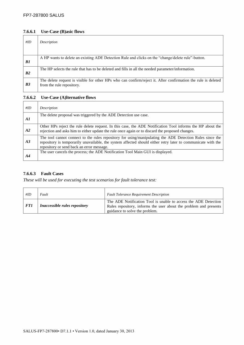
FP7-287800 SALUS
SALUS-FP7-287800• D7.1.1 • Version 1.0, dated January 30, 2013
7.6.6.1 Use-Case (B)asic flows
#ID Description
B1 A HP wants to delete an existing ADE Detection Rule and clicks on the “change/delete rule”-button.
B2 The HP selects the rule that has to be deleted and fills in all the needed parameter/information.
B3 The delete request is visible for other HPs who can confirm/reject it. After confirmation the rule is deleted
from the rule repository.
7.6.6.2 Use-Case (A)lternative flows
#ID Description
A1 The delete proposal was triggered by the ADE Detection use case.
A2 Other HPs reject the rule delete request. In this case, the ADE Notification Tool informs the HP about the
rejection and asks him to either update the rule once again or to discard the proposed changes.
A3 The tool cannot connect to the rules repository for using/manipulating the ADE Detection Rules since the
repository is temporarily unavailable, the system affected should either retry later to communicate with the
repository or send back an error message.
A4 The user cancels the process; the ADE Notification Tool Main GUI is displayed.
7.6.6.3 Fault Cases
These will be used for executing the test scenarios for fault tolerance test:
#ID Fault Fault Tolerance Requirement Description
FT1 Inaccessible rules repository The ADE Notification Tool is unable to access the ADE Detection
Rules repository, informs the user about the problem and presents
guidance to solve the problem.
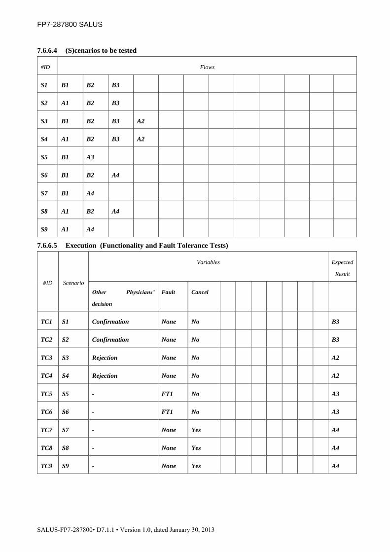
FP7-287800 SALUS
SALUS-FP7-287800• D7.1.1 • Version 1.0, dated January 30, 2013
7.6.6.4 (S)cenarios to be tested
#ID Flows
S1 B1 B2 B3
S2 A1 B2 B3
S3 B1 B2 B3 A2
S4 A1 B2 B3 A2
S5 B1 A3
S6 B1 B2 A4
S7 B1 A4
S8 A1 B2 A4
S9 A1 A4
7.6.6.5 Execution (Functionality and Fault Tolerance Tests)
#ID Scenario
Variables Expected
Result
Other Physicians’
decision
Fault Cancel
TC1 S1 Confirmation None No B3
TC2 S2 Confirmation None No B3
TC3 S3 Rejection None No A2
TC4 S4 Rejection None No A2
TC5 S5 - FT1 No A3
TC6 S6 - FT1 No A3
TC7 S7 - None Yes A4
TC8 S8 - None Yes A4
TC9 S9 - None Yes A4

FP7-287800 SALUS
SALUS-FP7-287800• D7.1.1 • Version 1.0, dated January 30, 2013
7.6.7 TC-6.1-7 ADE detection rule management
Description There are several cases where it is necessary to update/delete/add ADE detection
rules. This use case represents the management of the manipulation of the ADE
detection rules within the ADE Notification Tool.
Parent -
Included sub-
use cases
ADE detection rule validation
Extended sub-
use cases
-
Scope ADE Notification Tool
Actor(s) Physician A, Physician B, ADE Notification Tool
Goal The goal of this use case is to edit the ADE detection rule base.
Trigger This use case is initiated by the ADE detection use case or manually by a
Physician A.
Frequency Whenever an ADE detection rule has to be deleted, added or changed.
Minimal Post
conditions
-
Success Post
conditions
1. An ADE detection rule has been removed, added or changed.
7.6.7.1 Use-Case (B)asic flows
#ID Description
B1 A HP wants to manipulate the ADE Detection Rule repository and clicks on the “change/delete rule”- or
“add”-button.
B2 The HP confirms his entries. The manipulation request is visible for other HPs who can confirm/reject it.
B3 After confirmation the rule manipulation is applied to the detection rule repository. In the case that a rule has
to be implemented, this is done by the SALUS ADE Notification Tool Expert.
7.6.7.2 Use-Case (A)lternative flows
#ID Description
A1 The manipulation proposal was triggered by the ADE Detection use case.
A2 Other HP reject the manipulation request. In this case, the ADE Notification Tool informs the HP about the
rejection and asks him to either update his changes once again or to discard the proposed changes.
A3 The tool cannot connect to the rules repository for using/manipulating the ADE Detection Rules since the
repository is temporarily unavailable, the system affected should either retry later to communicate with the
repository or send back an error message.
A4 The user cancels the process; the ADE Notification Tool Main GUI is displayed.
A5 The rule that has to be implemented cannot be send to the SALUS ADE Notification Tool Expert due to
connectivity problems. The affected system should either retry later to communicate with the expert or send
back an error message.
7.6.7.3 Fault Cases
These will be used for executing the test scenarios for fault tolerance test:

FP7-287800 SALUS
SALUS-FP7-287800• D7.1.1 • Version 1.0, dated January 30, 2013
#ID Fault Fault Tolerance Requirement Description
FT1 Inaccessible rules repository The ADE Notification Tool is unable to access the ADE Detection
Rules repository, informs the user about the problem and presents
guidance to solve the problem.
FT2 Inaccessible SALUS ANT Expert The ADE Notification Tool is unable to access the ADE Notification
Tool Expert who has to implement new rules, informs the user about
the problem and presents guidance to solve the problem.
7.6.7.4 (S)cenarios to be tested
#ID Flows
S1 B1 B2 B3
S2 A1 B2 B3
S3 B1 B2 A2
S4 A1 B2 A2
S5 B1 A3
S6 A1 A3
S7 B1 A4
S8 A1 A4
S9 B1 B2 A5
S10 A1 B2 A5
7.6.7.5 Execution (Functionality and Fault Tolerance Tests)
#ID Scenario
Variables Expected
Result
Other Physicians’
decision
Fault Cancel
TC1 S1 Confirmation None No B3
TC2 S2 Confirmation None No B3
TC3 S3 Rejection None No A2
TC4 S4 Rejection None No A2
TC5 S5 - FT1 No A3
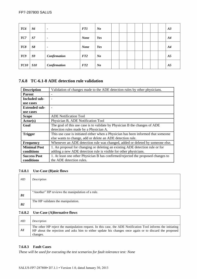
FP7-287800 SALUS
SALUS-FP7-287800• D7.1.1 • Version 1.0, dated January 30, 2013
TC6 S6 - FT1 No A3
TC7 S7 - None Yes A4
TC8 S8 - None Yes A4
TC9 S9 Confirmation FT2 No A5
TC10 S10 Confirmation FT2 No A5
7.6.8 TC-6.1-8 ADE detection rule validation
Description Validation of changes made to the ADE detection rules by other physicians.
Parent -
Included sub-
use cases
-
Extended sub-
use cases
-
Scope ADE Notification Tool
Actor(s) Physician B, ADE Notification Tool
Goal The goal of this use case is to validate by Physician B the changes of ADE
detection rules made by a Physician A.
Trigger This use case is initiated either when a Physician has been informed that someone
else wants to change, add or delete an ADE detection rule.
Frequency Whenever an ADE detection rule was changed, added or deleted by someone else.
Minimal Post
conditions
1. An proposal for changing or deleting an existing ADE detection rule or for
adding a new ADE detection rule is visible for other physicians.
Success Post
conditions
1. At least one other Physician B has confirmed/rejected the proposed changes to
the ADE detection rules.
7.6.8.1 Use-Case (B)asic flows
#ID Description
B1 “Another” HP reviews the manipulation of a rule.
B2 The HP validates the manipulation.
7.6.8.2 Use-Case (A)lternative flows
#ID Description
A1 The other HP reject the manipulation request. In this case, the ADE Notification Tool informs the initiating
HP about the rejection and asks him to either update his changes once again or to discard the proposed
changes.
7.6.8.3 Fault Cases
These will be used for executing the test scenarios for fault tolerance test: None

FP7-287800 SALUS
SALUS-FP7-287800• D7.1.1 • Version 1.0, dated January 30, 2013
7.6.8.4 (S)cenarios to be tested
#ID Flows
S1 B1 B2
S2 B1 A1
7.6.8.5 Execution (Functionality and Fault Tolerance Tests)
#ID Scenario
Variables Expected
Result
Other Physicians’
decision
TC1 S1 Confirmation B2
TC2 S2 Rejection A1
7.7 Test Case Definitions for Security and Privacy Toolset
7.7.1 TC-5.4-1 De-identify Clinical Data Instance
7.7.1.1 Use Case Template
Description
This use case is for removing key personal identification information from a clinical data
instance (either a complete medical summary, or parts of it). Such identification
information to be removed can belong to both the patients and also healthcare
professionals. De-identification is realized by the De-identification Service, upon the
request by SIL by invoking “UC-4.4-5 Query in SIL” or “UC-4.4-9 Subscribe to SALUS
SIL” use cases which are accessing Data Source. In the end, only the Patient Identifier
(PID) is left in the clinical data instance, which will then be replaced by a pseudonym
(PSN).
Parent NA
Scope De-identification Service
Actor(s) SIL
Goal Removing key personal identification information from a clinical data instance
Trigger Request for clinical data from a Data Source through SIL (“UC-4.4-5 Query in SIL” or
“UC-4.4-9 Subscribe to SALUS SIL” use cases) for clinical research purposes.
Frequency For each clinical data transfer/feed through SALUS SIL.
Preconditions
1. The clinical data instance to be de-identified is compiled in a format that is
recognized by the SIL, and hence the De-identification Service.
2. The de-identification algorithms are already implemented in the De-identification
Service.
3. De-identification Service and SIL reside in the same healthcare settings for security
and privacy related reasons.
4. SIL established a secure communication with the De-identification Service.
Minimal Post-
Conditions
1. De-identification Service informs the SIL about the result of the de-identification
operation.
Success Post-
Conditions
1. SIL successfully receives the de-identified clinical data instance from the De-
identification Service.

FP7-287800 SALUS
SALUS-FP7-287800• D7.1.1 • Version 1.0, dated January 30, 2013
7.7.1.2 Use-Case (B)asic flows
#ID Description
B1 SIL sends the clinical data instance to the De-identification Service.
B2 De-identification Service retrieves the clinical data instance and determines the format of the data.
B3 By applying the de-identification algorithms implemented according to the format of the data and the used
content model template/ontology, De-identification Service either removes or generalizes key personal
identification information in the clinical data instance. It just keeps the Patient Identifier (PID), which will be
replaced with a pseudonym (PSN) later.
B4 De-identification Service returns back the de-identified clinical data instance to SIL.
7.7.1.3 Use-Case (A)lternative flows
#ID Description
A1 De-identification Service does not recognize the format of the clinical data instance. De-identification Service
informs SIL about the problem, and presents the recognized data formats and templates/archetypes.
7.7.1.4 Fault Cases
These will be used for executing the test scenarios for fault tolerance test:
#ID Fault Fault Tolerance Requirement Description
FT1 Unrecognizable format De-identification Service does not recognize the format of the
clinical data instance. De-identification Service informs SIL about
the problem, and presents the recognized data formats and
templates/archetypes.
7.7.1.5 (S)cenarios to be tested
#ID Flows
S1 B1 B2 B3 B4
S2 B1 B2 A1
7.7.1.6 Execution
#ID Scenario
Variables Expected
Result
Fault
TC1 S1 None B4
TC2 S2 FT1 A1

FP7-287800 SALUS
SALUS-FP7-287800• D7.1.1 • Version 1.0, dated January 30, 2013
7.7.2 TC-5.4-2 Pseudonymize Clinical Data
7.7.2.1 Use Case Template
Description
This use case is for replacing the Patient Identifier (PID) that exists in a clinical data
instance, which can be an ICSR, CDA, 13606 or content model ontology instance, with a
pseudonym (PSN). For this reason, SIL (which accesses the Data Source to retrieve the
clinical data instance), sends the clinical data instance where medical data is encrypted,
and presents the Data Requester/Data Target’s end point so that the Pseudonymization
Service can replace the PID with a PSN and sends the encrypted clinical data to the
specified Data Requester/Data Target.
Parent NA
Scope Pseudonymization Service
Actor(s) SIL, Data Requester/Data Target
Goal Replacing PID in a clinical data instance with a PSN
Trigger Request for clinical data from an EHR System / Data Warehouse through SIL for clinical
research purposes
Frequency For each clinical data transfer/feed through SALUS SIL.
Preconditions
1. The clinical data to be pseudonymized is already de-identified through the “UC-5.4-1
De-identify Clinical Data Instance” use case
2. The encryption methods for pseudonymization are already implemented in the
Pseudonymization Service. It is foreseen that reversible encryption is more suitable
for SALUS purposes, since in some cases (e.g. follow-up requests) it is necessary to
re-identify the patient data.
3. SIL established a secure communication with the Pseudonymization Service.
4. Medical data in clinical data set to be pseudonymized is encrypted with the public key
of the Data Requester/Data Target, so that Pseudonymization service will not be able
to access medical data
Minimal Post-
Conditions
1. Pseudonymization Service informs SIL about the result of the pseudonym creation
operation.
2. Pseudonymization Service is hosted by a trusted third party
3. Pseudonymization Service implements an effective sender authentication and
authorization that prevents a trial encryption attack.
Success Post-
Conditions
1. Data Requester/Data Target successfully receives Pseudonymized clinical data set
where the PID is replaced with the PSN in the clinical data instances
7.7.2.2 Use-Case (B)asic flows
#ID Description
B1 SIL (which communicates with Data source to retrieve clinical data instances) sends the clinical data set
including the PID where medical data is encrypted to the Pseudonymization Service. The endpoint of the
Data Requester/Data Target is also passed in this request.
B2 By applying the encryption methods implemented, Pseudonymization Service generates the corresponding
pseudonym (PSN) for the PID.
B3 Pseudonymization Service replaces the PID in the clinical data set with PSN and passes it to the end point of
the Data Requester/Data Target.
B4 Pseudonymization Service notifies SIL about the result of the operation.
7.7.2.3 Use-Case (A)lternative flows
#ID Description
A1 Pseudonymization Service is not able to generate PSN for the provided PID. Pseudonymization Service
informs SIL about the problem with an error report (e.g. PID is too short), and requests it to retry the
operation.
7.7.2.4 Fault Cases
These will be used for executing the test scenarios for fault tolerance test:

FP7-287800 SALUS
SALUS-FP7-287800• D7.1.1 • Version 1.0, dated January 30, 2013
#ID Fault Fault Tolerance Requirement Description
FT1 Unable to generate PSN Pseudonymization Service is not able to generate PSN for the
provided PID. Pseudonymization Service informs SIL about the
problem with an error report (e.g. PID is too short), and requests it to
retry the operation.
7.7.2.5 (S)cenarios to be tested
#ID Flows
S1 B1 B2 B3 B4
S2 B1 A1
7.7.2.6 Execution
#ID Scenario
Variables Expected
Result
Fault
TC1 S1 None B4
TC2 S2 FT1 A1
7.7.3 TC-5.4-3 Re-identify a Pseudonym
7.7.3.1 Use Case Template
Description
This use case is for re-identifying a pseudonym (PSN); i.e. replacing the PSN
corresponding Patient Identifier (PID) for a PSN in a query/notification about a specific
patient that needs to be sent back to Data Source. In some cases, it is necessary to do re-
identification, for instance for tracing case reports to their corresponding patient records
for providing detailed information on extended parts of the underlying medical history of
the patient.
Parent -
Scope Pseudonymization Service
Actor(s) Data Requester/Data Target, SIL
Goal Retrieving the corresponding PID for a PSN
Trigger
Request by the Safety Analyst in the regulatory authority for tracing a case report to its
corresponding patient records for getting more detailed information or presenting a
notification about a specific patient back to Data Source.
Frequency Whenever clinical review of ADEs is required/or notification about a specific patient back
to Data Source needs to be sent.
Preconditions
1. The pseudonym that is available within a query/notification is previously generated by
the same Pseudonymization Service within the “UC-5.4-2 Pseudonymize Clinical
Data” use case.
2. The reversible encryption methods for re-identification are already implemented in the
Pseudonymization Service.

FP7-287800 SALUS
SALUS-FP7-287800• D7.1.1 • Version 1.0, dated January 30, 2013
3. Data Requester/Data Target established a secure communication with the
Pseudonymization Service.
4. Pseudonymization Service is hosted by a trusted third party
5. Pseudonymization Service implements an effective sender authentication and
authorization that prevents a trial encryption attack.
Minimal Post-
Conditions
1. Pseudonymization Service informs the Data Requester/Data Target about the result of
the re-identification operation.
Success Post-
Conditions
1. Pseudonymization Service successfully creates the PID corresponding to the PSN,
replaces the PSN with the PID, and forwards the query/notification about a specific
patient data to the Data Source through SIL and TIL.
7.7.3.2 Use-Case (B)asic flows
#ID Description
B1 Data Requester/Data Target sends the query/notification about a specific patient data including the
pseudonym (PSN) to the Pseudonymization Service. The end point of the Data Source is also provided in this
method as a parameter.
B2 Pseudonymization Service generates the corresponding Patient Identifier (PID) for the PSN and replaces the
PSN with the PID, and forwards the query/notification about a specific patient data to the Data Source
through SIL.
B3 Pseudonymization Service sends a notification to the Data Requester/Data Target about the result of the
operation.
7.7.3.3 Use-Case (A)lternative flows
#ID Description
A1 Pseudonymization Service is not able to generate the corresponding PID for the provided PSN.
Pseudonymization Service informs the Data Requester/Data Target about the problem with a report (e.g. PSN
too short, no corresponding PID exists), and requests it to retry the operation.
7.7.3.4 Fault Cases
These will be used for executing the test scenarios for fault tolerance test:
#ID Fault Fault Tolerance Requirement Description
FT1 Unable to generate PID Pseudonymization Service is not able to generate the corresponding
PID for the provided PSN. Pseudonymization Service informs the
Data Requester/Data Target about the problem with a report (e.g.
PSN too short, no corresponding PID exists), and requests it to retry
the operation.

FP7-287800 SALUS
SALUS-FP7-287800• D7.1.1 • Version 1.0, dated January 30, 2013
7.7.3.5 (S)cenarios to be tested
#ID Flows
S1 B1 B2 B3
S2 B1 A1
7.7.3.6 Execution
#ID Scenario
Variables Expected
Result
Fault
TC1 S1 None B3
TC2 S2 FT1 A1
7.7.4 TC-5.4-4 Audit Logging
7.7.4.1 Use Case Template
Description This use case is for Auditing all kinds of interactions in/out Data Requester/Data Target
and Data Source.
Parent NA
Scope Audit Repository
Actor(s) Secure Node (Data Requester/Data Target, Data Source, SIL, TIL)
Goal Auditing all kinds of interactions in/out Data Requester/Data Target and Data Source
Trigger Whenever a clinical data exchange is done between Data Requester/Data Target and Data
Source
Frequency Whenever a clinical data exchange is done between Data Requester/Data Target and Data
Source
Preconditions
1. An Audit Repository is set up, which accepts audit messages in compliance to IHE
ATNA Profile.
2. Secure Node has the necessary certificates
3. Secure Node has established a secure communication with the Audit Repository.
Minimal Post-
Conditions 1. Audit Repository notifies the result of the operation to Secure Node.
Success Post-
Conditions
1. Audit records are successfully saved to Audit Repository and available for viewing in
Audit Repository interface

FP7-287800 SALUS
SALUS-FP7-287800• D7.1.1 • Version 1.0, dated January 30, 2013
7.7.4.2 Use-Case (B)asic flows
#ID Description
B1 After each transaction in/out of Data Requester/Data Target and Data Source, Data Requester/Data Target
and Data Source, SIL, TIL (Secure Node) will send ITI-20 Record Audit Event transaction to Audit
Repository.
B2 Audit Repository saves these Audit Records.
B3 An authorized user can see the audit records from an interface provided by Audit Repository.
7.7.4.3 Use-Case (A)lternative flows
#ID Description
A1 Audit Repository is not able to process the audit log it receives. Audit Repository informs the Secure Node
about the problem with an error report.
7.7.4.4 Fault Cases
These will be used for executing the test scenarios for fault tolerance test:
#ID Fault Fault Tolerance Requirement Description
FT1 Unable to process audit log Audit Repository is not able to process the audit log it receives.
Audit Repository informs the Secure Node about the problem with
an error report.
7.7.4.5 (S)cenarios to be tested
#ID Flows
S1 B1 B2 B3
S2 B1 A1
7.7.4.6 Execution
#ID Scenario
Variables Expected
Result
Fault
TC1 S1 None B3
TC2 S2 FT1 A1

FP7-287800 SALUS
SALUS-FP7-287800• D7.1.1 • Version 1.0, dated January 30, 2013
7.8 Safety Analysis Tools
7.8.1 TC-6.2-1 Query Population Data for Safety Analysis
Description This use case is enabling querying underlying Data Sources for EHR extracts of the selected
patient population for safety analysis.
Parent -
Included sub-
use cases
UC-4.4-5 Query in SIL
UC-5.2-1 Query SIL through TIL
Extended sub-
use cases
-
Scope Safety Analysis Tool
Actor(s) Safety Analyst, Data Source, Technical Interoperability Layer (TIL), Semantic
Interoperability Layer (SIL)
Goal Enabling querying underlying Data Sources for EHR extracts of the selected patient
population for safety analysis.
Trigger This use case is initiated by the Safety Analyst in the Pharmacovigilance Center.
Frequency Runs whenever the Safety Analyst wants to conduct a safety analysis study based on
population data.
Minimal post
conditions
Safety Analysis Tool presents the result of the query process.
Success post
conditions
Safety Analysis Tool presents the collected population data in a de-identified and
pseudonymized manner to the Safety Analyst in the data model preferred

FP7-287800 SALUS
SALUS-FP7-287800• D7.1.1 • Version 1.0, dated January 30, 2013
7.8.1.1 Use-Case (B)asic flows
#ID Description
B1 Safety Analysis Tool queries the Data Sources either through the “UC-5.2-1 Query SIL through TIL” use
case (if it wants to utilize the functional interoperability profiles supported by SALUS) or directly through
“UC-4.4-5 Query in SIL” use case (by specifying the eligibility criteria for the patient population
semantically on top of SALUS core ontology)
B2 Result data set from the Data Source(s) is returned in a de-identified, pseudonymized way to Safety Analyst
through Safety Analysis Tool Interface
B3 Additional means provided by the Safety Analysis Tool conduct safety analysis (like characterizing the cases
and contrasting them to a background population; temporal pattern characterization; visualization of selected
parameters in patient history) on top of the retrieved data sets, and present the analysis results graphically to
the Safety Analyst.
7.8.1.2 Use-Case (A)lternative flows
#ID Description
A1 Safety Analysis Tool is unable to access the underlying Data Source(s). Safety Analysis Tool informs the
Safety Analyst about the problem and presents guidance to solve it.
A2 Empty result is returned by the Data Source(s), since there were no records matching the queries. Safety
Analysis Tool informs the Safety Analyst about this fact.
A3 Safety Analysis Tool retrieves result data sets from the Data Source(s), but unable to process them
appropriately as they are not in the expected format. Safety Analysis Tool informs the Safety Analyst about
the problem and presents guidance to solve it.
A4 The means provided by the Safety Analysis Tool (like characterizing the cases and contrasting them to a
background population; temporal pattern characterization; visualization of selected parameters in patient
history) is not able to present the results of the analysis process run on top of retrieved data sets, to the Safety
Analyst. Safety Analysis Tool informs the Safety Analyst about the problem and presents guidance to solve it.
7.8.1.3 Fault Cases
These will be used for executing the test scenarios for fault tolerance test:

FP7-287800 SALUS
SALUS-FP7-287800• D7.1.1 • Version 1.0, dated January 30, 2013
#ID Fault Fault Tolerance Requirement Description
FT1 Inaccessible Data Source(s) Safety Analysis Tool is unable to access the underlying Data
Source(s). Safety Analysis Tool informs the Safety Analyst about the
problem and presents guidance to solve it.
FT2 Unsupported Result Data Set
Format
Safety Analysis Tool retrieves result data sets from the Data
Source(s), but unable to process them appropriately as they are not in
the expected format. Safety Analysis Tool informs the Safety
Analyst about the problem and presents guidance to solve it.
FT3 Analysis process is unable to
conclude successfully
The means provided by the Safety Analysis Tool (like characterizing
the cases and contrasting them to a background population; temporal
pattern characterization; visualization of selected parameters in
patient history) is not able to present the results of the analysis
process run on top of retrieved data sets, to the Safety Analyst.
Safety Analysis Tool informs the Safety Analyst about the problem
and presents guidance to solve it.
7.8.1.4 (S)cenarios to be tested
#ID Flows
S1 B1 B2 B3 B4
S2 B1 A1
S3 B1 A2
S4 B1 B2 A3
S5 B1 B2 B3 A4
7.8.1.5 Execution (Functionality and Fault Tolerance Tests)
#ID Scenario
Variables Expected
Result
Content Model Type Fault
TC1 S1 DS: Semantic Aware /
RS: OMOP
None B4
TC2 S1 DS: Semantic Aware /
RS: ROCHE
None B4
TC3 S1 DS: Not Semantic
Aware / RS: OMOP
None B4
TC4 S1 DS: Not Semantic
Aware / RS: ROCHE
None B4
TC5 S2 DS: Semantic Aware FT1 A1

FP7-287800 SALUS
SALUS-FP7-287800• D7.1.1 • Version 1.0, dated January 30, 2013
TC6 S2 DS: Not Semantic
Aware
FT1 A1
TC7 S3 DS: Semantic Aware None A2
TC8 S3 DS: Not Semantic
Aware
None A2
TC9 S4 RS: OMOP FT2 A3
TC10 S4 RS: ROCHE FT2 A3
TC11 S5 RS: OMOP FT3 A4
TC12 S5 RS: ROCHE FT3 A4
DS: Data Source, RS: Result Set
7.8.2 TC-6.2-2 Query Population Data for Case Series Characterization
Description This use case is a specialization of “UC-6.2-1 Query Population Data for Safety Analysis” use
case. Data Sources are queried for EHR extracts of selected patient populations to
characterize ADE cases that originate from SALUS EHR data and compare the statistics
against a custom background population.
Parent UC-6.2-1 Query Population Data for Safety Analysis
Included sub-
use cases
UC-4.4-5 Query in SIL
UC-5.2-1 Query SIL through TIL
Extended sub-
use cases
-
Scope Case Series Characterization (CSC) Tool
Actor(s) Safety Analyst, Data Source, Technical Interoperability Layer (TIL), Semantic
Interoperability Layer (SIL)
Goal Enabling querying underlying Data Sources for EHR extracts of the selected patient
populations for characterizing the ADE cases that originate from SALUS EHR data and
compare the statistics against a custom background population.
Trigger This use case is initiated by the Safety Analyst in the Pharmacovigilance Center.
Frequency Runs whenever the Safety Analyst wants to conduct a safety analysis study to characterize
ADE cases that originate from SALUS EHR data and compare the statistics against a custom
background population.
Minimal post
conditions
Case Series Characterization Tool presents the result of the query process.
Success post
conditions
Case Series Characterization Tool presents the results of the analysis that it conducted on top
of the collected de-identified and pseudonymized population data.
This test case is a specialization of TC-6.2-1 Query Population Data for Safety Analysis, and hence all the
information such as basic flows, alternative flows, fault cases, scenarios to be tested and test execution
scheme are identical with TC-6.2.1. All test executions of TC-6.2.1 should be repeated similarly for this test
case.

FP7-287800 SALUS
SALUS-FP7-287800• D7.1.1 • Version 1.0, dated January 30, 2013
7.8.3 TC-6.2-3 Query Population Data for Temporal Pattern Characterization
Description This use case is a specialization of “UC-6.2-1 Query Population Data for Safety Analysis” use
case. Underlying Data Sources are queried for EHR extracts of selected patient populations
for temporal pattern characterization, to visualize the association between a medication and an
event to enhance the analyzing capabilities of the Safety Analyst.
Parent UC-6.2-1 Query Population Data for Safety Analysis
Included sub-
use cases
UC-4.4-5 Query in SIL
UC-5.2-1 Query SIL through TIL
Extended sub-
use cases
-
Scope Temporal Pattern Characterization (TPC) Tool
Actor(s) Safety Analyst, Data Source, Technical Interoperability Layer (TIL), Semantic
Interoperability Layer (SIL)
Goal Enabling querying underlying Data Sources for EHR extracts of the selected patient
populations for temporal pattern characterization, to visualize the association between a
medication and an event to enhance the analyzing capabilities of the Safety Analyst.
Trigger This use case is initiated by the Safety Analyst in the Pharmacovigilance Center.
Frequency Runs whenever the Safety Analyst wants to conduct a safety analysis visualize the association
between a medication and an event.
Minimal post
conditions
Temporal Pattern Characterization Tool presents the result of the query process.
Success post
conditions
Temporal Pattern Characterization Tool presents the results of the analysis that it conducted
on top of the collected de-identified and pseudonymized population data.
This test case is a specialization of TC-6.2-1 Query Population Data for Safety Analysis, and hence all the
information such as basic flows, alternative flows, fault cases, scenarios to be tested and test execution
scheme are identical with TC-6.2.1. All test executions of TC-6.2.1 should be repeated similarly for this test
case.
7.8.4 TC-6.2-4 Visualizing Patient History
Description This use case is an extension of “UC-6.2-1 Query Population Data for Safety Analysis” use
case. After querying underlying Data Sources for EHR extracts of the selected patient
populations, these de-identified and pseudonymized EHR extracts are stored in a local
repository and through an interface the Safety Analyst can view detailed information about
single patients like previous/active Medications, Problems, Diagnoses, Allergies, Conditions
and Lab Values
Parent -
Included sub-
use cases
-
Extended sub-
use cases
UC-6.2-1 Querying Population Data for Safety Analysis
Scope Patient History Tool
Actor(s) Safety Analyst
Goal Enabling visualising the related sections of the collected EHR extracts as a result of a
population query to Data Sources.
Trigger This use case is initiated by the Safety Analyst in the Pharmacovigilance Center.
Frequency Runs whenever the Safety Analyst wants to visualize the collected EHR extracts.
Minimal post
conditions
Patient History Tool presents the collected EHR extracts as a result of a population query to
Data Sources.
Success post Patient History Tool presents the collected EHR extracts as a result of a population query to

FP7-287800 SALUS
SALUS-FP7-287800• D7.1.1 • Version 1.0, dated January 30, 2013
conditions Data Sources.
7.8.4.1 Use-Case (B)asic flows
#ID Description
B1 The Safety Analyst specifies sections of the EHR extracts of interest
B2 The Patient History Tool retrieves from the local repository information of interest according to the requested
sections.
B3 The Safety Analyst views detailed information about the patient of interest through the Patient History Tool,
such as previous/active Medications, Problems, Diagnoses, Allergies and Lab Values.
7.8.4.2 Use-Case (A)lternative flows
#ID Description
A1 Patient History Tool is unable to access the underlying local repository. Patient History Tool informs the
Safety Analyst about the problem and presents guidance to solve it.
A2 There is no information about the patient in the local repository. Patient History Tool informs the Safety
Analyst about this fact.
A3 Patient History Tool retrieves some results from the local repository, but due to some internal problems such
as the inability to parse the retrieved results, it is not able to present the results to the Safety Analyst. Patient
History Tool informs the Safety Analyst about the problem and presents guidance to solve it.
7.8.4.3 Fault Cases
These will be used for executing the test scenarios for fault tolerance test:

FP7-287800 SALUS
SALUS-FP7-287800• D7.1.1 • Version 1.0, dated January 30, 2013
#ID Fault Fault Tolerance Requirement Description
FT1 Inaccessible Local Repository Patient History Tool is unable to access the underlying local
repository. Patient History Tool informs the Safety Analyst about the
problem and presents guidance to solve it.
FT2 Not able to present the available
results
Patient History Tool retrieves some results from the local repository,
but due to some internal problems such as the inability to parse the
retrieved results, it is not able to present the results to the Safety
Analyst. Patient History Tool informs the Safety Analyst about the
problem and presents guidance to solve it.
7.8.4.4 (S)cenarios to be tested
#ID Flows
S1 B1 B2 B3
S2 B1 A1
S3 B1 B2 A2
S4 B1 B2 A3
7.8.4.5 Execution (Functionality and Fault Tolerance Tests)
#ID Scenario
Variables Expected
Result
Fault
TC1 S1 None B3
TC2 S2 FT1 A1
TC3 S3 None A2
TC4 S4 FT2 A3
7.8.5 TC-6.2-5 Subscribe to Population Data for Signal Detection
Description This use case is enabling subscribing to Data Sources to retrieve selected sections of EHR
extracts for a given patient population to a separate Safety Analysis Repository for running
signal detection algorithms.
Parent -
Included sub-
use cases
UC-4.4-9 Subscribe to SALUS SIL
UC-5.1-1 Subscription for Clinical Data through TIL
Extended sub- -

FP7-287800 SALUS
SALUS-FP7-287800• D7.1.1 • Version 1.0, dated January 30, 2013
use cases
Scope Exploratory Analysis Tool
Actor(s) Safety Analyst, Data Source, Technical Interoperability Layer (TIL), Semantic Interoperability
Layer (SIL), Safety Analysis Repository, Signal Detection Agent
Goal Enabling subscribing to Data Sources to retrieve selected sections of EHR extracts for a given
patient population to a separate Safety Analysis Repository for running signal detection
algorithms.
Trigger This use case is initiated by the Safety Analyst in Pharmacovigilance Center
Frequency Runs continuously to collect the subscribed data set from Data Sources (EHRs/Data
warehouses) for an initiated signal detection study
Minimal post
conditions
Exploratory Analysis Tool Interface presents the result of the analysis
Success post
conditions
Signal Detection Agent is able to run on top of the collected data in the Safety Analysis
Repository and present the detected potential signals.
7.8.5.1 Use-Case (B)asic flows
#ID Description
B1 Exploratory Analysis Tool subscribes to the Data Sources either through the “UC-5.1-1 Subscription for
Clinical Data through TIL” use case (if it wants to utilize the functional interoperability profiles supported by
SALUS) or directly through “UC-4.4-9 Subscribe to SALUS SIL” use case (by specifying the eligibility
criteria for the patient population semantically on top of SALUS core ontology)
B2 Whenever a subscribed event is fired in the Data Source(s), the subscribed data set is returned in a de-
identified, pseudonymized way in the preferred format of Signal Detection Agent.
B3 The returned data sets are stored in the selected Safety Analysis Repository
B4 The Signal Detection Agent runs on top of the Safety Analysis Repository, and results are presented through
the Exploratory Analysis Tool Interface
7.8.5.2 Use-Case (A)lternative flows
#ID Description
A1 Exploratory Analysis Tool is unable to access the underlying Data Source(s) for subscription. Exploratory
Analysis Tool informs the Safety Analyst about the problem and presents guidance to solve it.
A2 Exploratory Analysis Tool retrieves result data sets from the subscribed Data Source(s), but it is unable to
process them appropriately as they are not in the expected format. Exploratory Analysis Tool informs the
Safety Analyst about the problem and presents guidance to solve it.
A3 The retrieved results are not able to be stored in the Safety Analysis Repository since it is unavailable.
Exploratory Analysis Tool informs the Safety Analyst about the problem and presents guidance to solve it.
A4 The Signal Detection Agent is not able to conclude successfully the analysis process run on top of the data in
the Safety Analysis Repository, so that Exploratory Analysis Tool Interface is not able to present them to the
Safety Analyst. Exploratory Analysis Tool informs the Safety Analyst about the problem and presents
guidance to solve it.
7.8.5.3 Fault Cases
These will be used for executing the test scenarios for fault tolerance test:

FP7-287800 SALUS
SALUS-FP7-287800• D7.1.1 • Version 1.0, dated January 30, 2013
#ID Fault Fault Tolerance Requirement Description
FT1 Inaccessible Data Source(s) Exploratory Analysis Tool is unable to access the underlying Data
Source(s) for subscription. Exploratory Analysis Tool informs the
Safety Analyst about the problem and presents guidance to solve it.
FT2 Unsupported Result Data Set
Format
Exploratory Analysis Tool retrieves result data sets from the
subscribed Data Source(s), but it is unable to process them
appropriately as they are not in the expected format. Exploratory
Analysis Tool informs the Safety Analyst about the problem and
presents guidance to solve it.
FT3 Unavailable Safety Analysis
Repository
The retrieved results are not able to be stored in the Safety Analysis
Repository since it is unavailable. Exploratory Analysis Tool
informs the Safety Analyst about the problem and presents guidance
to solve it.
FT4 Analysis process is unable to
conclude successfully
The Signal Detection Agent is not able to conclude successfully the
analysis process run on top of the data in the Safety Analysis
Repository, so that Exploratory Analysis Tool Interface is not able to
present them to the Safety Analyst. Exploratory Analysis Tool
informs the Safety Analyst about the problem and presents guidance
to solve it.
7.8.5.4 (S)cenarios to be tested
#ID Flows
S1 B1 B2 B3 B4
S2 B1 A1
S3 B1 B2 A2
S4 B1 B2 A3
S5 B1 B2 B3 A4
7.8.5.5 Execution (Functionality and Fault Tolerance Tests)
#ID Scenario
Variables Expected
Result
Content Model Type Fault
TC1 S1 DS: Semantic Aware /
RS: OMOP
None B4
TC2 S1 DS: Not Semantic
Aware / RS: OMOP
None B4
TC3 S2 DS: Semantic Aware FT1 A1
TC4 S2 DS: Not Semantic
Aware
FT1 A1

FP7-287800 SALUS
SALUS-FP7-287800• D7.1.1 • Version 1.0, dated January 30, 2013
TC5 S3 RS: OMOP FT2 A2
TC6 S4 RS: OMOP FT3 A3
TC7 S5 RS: OMOP FT4 A4
DS: Data Source, RS: Result Set

FP7-287800 SALUS
SALUS-FP7-287800• D7.1.1 • Version 1.0, dated January 30, 2013
APPENDIX 3. REQUIREMENTS TRACEABILITY MATRIX
This section consists of a summary of all requirements collected from D3.3.1 and that will continue to be
updated during the course of the SALUS development and evaluation. These requirements need to be on this
deliverable since some of them can change since the publication of D3.3.1 and the updated requirements are
reported here.
For clearness of arrangement the requirement are separated in the different categories:
Functional (coming from uses cases)
Interface (related to the Graphic user Interfaces, and System Interfaces)
Non functional
Data
Depending on the category of the requirements a set of attributes will be associated to each requirement. The
significant attributes are:
RE-ID: A unique identifier for the requirement. It will be composed of three parts:
“R”+”Type of requirement – “+“enumerator”
Requirement text: The explanation of the requirement.
Liability: The liability of the requirement. Shall is a “must” requirement, Should is an
“optional” requirement, and Obsolete identifies a requirement that is not necessary any more.
Status: The status of the requirement, if it is proposed, validated, rejected, designed,
implemented, or tested.

FP7-287800 SALUS
SALUS-FP7-287800• D7.1.1 • Version 1.0, dated January 30, 2013

FP7-287800 SALUS
SALUS-FP7-287800• D7.1.1 • Version 1.0, dated January 30, 2013 Page 140 of 163
Functional Requirements
RE-ID Requirement text Liability Status
Requirements for Common Data Element (CDE) Repository
FR-42-1
CDE Repository shall implement mechanisms for authenticating and authorizing Domain Experts
Shall Proposed
FR-42-2 CDE Repository should implement mechanisms to parse models in different formats (including UML, ontology, ADL1.4, XSD)
Should Proposed
FR-42-3 CDE Repository should implement mechanisms to import UML Models to the CDE Repository
Should Proposed
FR-42-4 CDE Repository shall implement mechanisms to import Content Models represented through an XSD model like HL7 CDA
templates (together with necessary supporting files such as Schematrons), CDISC ODM message specifications or through ADL 1.4
like CEN 13606 templates to the CDE Repository
Shall Proposed
FR-42-5 CDE Repository shall implement mechanisms to import Local Domain Ontologies to the CDE Repository
Shall Proposed
FR-42-6 CDE Repository shall implement mechanisms to represent the parsed content models as a new Content Model Ontology
Shall Proposed

FP7-287800 SALUS
SALUS-FP7-287800• D7.1.1 • Version 1.0, dated January 30, 2013 Page 141 of 163
FR-42-7 CDE Repository shall implement mechanisms to add the created Content Model Ontology to the SALUS Semantic Resource Set
Shall Proposed
FR-42-8 CDE Repository shall provide feedback to the Domain Expert about the result of the import operations
Shall
Proposed
FR-42-9 CDE Repository shall present error message when it is unable to access or parse the file content to be imported (could be UML
model, XSD schema, Schematron or archetype definition)
Shall Proposed
FR-42-10 CDE Repository shall implement mechanisms to parse the Content Model ontologies and identify candidate CDEs Shall Proposed
FR-42-11 CDE Repository should implement mechanisms to semi-automatically annotate the identified candidate CDEs with terminology
codes Should
Proposed
FR-42-12 CDE Repository should provide mechanisms to enable the Domain Expert to choose from the discovered matching CDEs to annotate
the candidate CDEs Should
Proposed
FR-42-13 CDE Repository shall provide mechanisms to curate new CDEs based on candidate CDEs Shall Proposed
FR-42-14 CDE Repository shall provide mechanisms to store the annotated (with the existing CDEs in the CDE Repository) Content Model
Ontology
Shall Proposed
FR-42-15 CDE Repository shall provide feedback to the Domain Expert about the result of the annotation operation Shall Proposed
FR-42-16 CDE Repository shall implement mechanisms to search CDEs through selected search criteria, which could be keywords, selected
terminology codes, or a candidate CDE.
Shall Proposed
FR-42-17 Similarity search and several filtering mechanisms should be available for the use of the Domain Expert.
Should
Proposed

FP7-287800 SALUS
SALUS-FP7-287800• D7.1.1 • Version 1.0, dated January 30, 2013 Page 142 of 163
FR-42-18 CDE Repository shall implement mechanisms to let the Domain Expert browse, filter and view the CDEs. Shall Proposed
FR-42-19 CDE Repository shall implement mechanisms to export the SALUS Core Ontology from the available CDEs maintained in the
repository
Shall Proposed
Requirements for SALUS Semantic Interoperability Layer
FR-4.3-1
System shall implement mechanisms for graphically and semi-automatically mapping Content Model Ontologies to SALUS Core
Ontology Shall
Proposed
FR-4.3-2 System shall implement mechanisms for defining mapping rules among the elements (i.e. a class) from the source Content Model
Ontology and the elements (i.e. a class) in the SALUS Core Ontology Shall
Proposed
FR-4.3-3 OPTIONAL. Mapping mechanism should use the annotated Content Ontology (if available) to propose candidate mappings to the
Domain Expert. Should
Proposed
FR-4.3-4 System shall implement mechanisms to add the mapping definitions and rules to the SALUS Semantic Resource Set.
Shall
Proposed
FR-4.3-5 System shall present error messages to the Domain Expert if saving of the mapping definition is not successful.
Shall
Proposed
FR-4.3-6 System shall implement mechanisms for adding a Terminology System (a subset, or the complete content), which did not exist in the
knowledge base of the SIL previously, as an ontology to extend the SALUS Semantic Resource Set Shall
Proposed
FR-4.3-7 System shall implement mechanisms to define rules to align the Terminology System Ontology with the SALUS Core Ontology
Shall
Proposed
FR-4.3-8 System shall implement mechanisms to store the alignment rules between Terminology System Ontology and the SALUS Core
Ontology to be run by SIL when necessary. Shall
Proposed

FP7-287800 SALUS
SALUS-FP7-287800• D7.1.1 • Version 1.0, dated January 30, 2013 Page 143 of 163
FR-4.3-9 System shall implement mechanisms to define mappings between codes from different terminology systems
Shall
Proposed
FR-4.3-10 System shall implement mechanisms to define mappings between two different terminology systems
Shall
Proposed
FR-4.3-11 System shall implement mechanisms to retrieve mapping information between a source code in a terminology system to a target code
in another terminology system from a publicly available terminology repository Shall
Proposed
FR-4.3-12 System shall implement mechanisms for searching terminology system codes by code and by designation
Shall
Proposed
FR-4.3-13 System shall provide error messages when it fails to access a remote terminology repository
Shall
Proposed
FR-4.3-14 System shall provide warning messages when the Terminology Expert tries to define a mapping that already exists
Shall
Proposed
FR-4.3-15 System shall implement mechanisms for adding an external domain ontology to SALUS Semantic Resource Set to extend the
reasoning capabilities Shall
Proposed
FR-4.3-16 System shall implement mechanisms for aligning an external domain ontology with the SALUS Core Ontology
Shall
Proposed
FR-4.3-17 System shall implement mechanisms to save the alignment rules between external domain ontologies and SALUS Core Ontology
Shall
Proposed
FR-4.4-1
SIL shall implement a service for translating an XML instance to the ontological representation of the clinical data.
Shall
Proposed
FR-4.4-2 SIL shall implement a mechanism to translate the ontological representation of the clinical data instance (yet, it is an instance of a
Content Model Ontology) to an ontological instance in SALUS Core Ontology, according to the previously defined mapping
definitions and rules. Shall
Proposed

FP7-287800 SALUS
SALUS-FP7-287800• D7.1.1 • Version 1.0, dated January 30, 2013 Page 144 of 163
FR-4.4-3 SIL shall implement a mechanism to retrieve the clinical data instances from Data Sources in SALUS Core Ontology
Shall
Proposed
FR-4.4-4 SIL shall provide an error message when the native representation format of the original clinical data instance is not recognized
Shall
Proposed
FR-4.4-5 SIL shall generate an error report when the necessary mapping definitions and rules are not available.
Shall
Proposed
FR-4.4-6 SIL shall implement mechanisms for translation of the clinical data instance represented in SALUS Core Ontology to the
corresponding ontological representation of the target content model ontology according to the previously defined mapping
definitions and rules Shall
Proposed
FR-4.4-7 SIL should implement mechanisms to translate the clinical data instance in target semantic model to the clinical data in target
representation syntax (e.g. an XML instance complying with the specific target XML schema).
Should
Proposed
Requirements for Technical Interoperability Layer Part 1: Subscription Based Interoperability Profiles and Open Source
Toolsets
FR-5.1-1 TIL shall provide standardized interface for subscribing, unsubscribing and retrieving data from Data Source(s)
Shall
Proposed
FR-5.1-2 TIL shall provide two level of interfaces: (1) subscription interfaces to be used by Data Requester system actors like ADE
Notification Tool to subscribe to Data Source(s) through SIL; (2)subscription interfaces to be implemented on top of Data Source(s)
to be used by SIL to communicate with the Data Source(s). Shall
Proposed

FP7-287800 SALUS
SALUS-FP7-287800• D7.1.1 • Version 1.0, dated January 30, 2013 Page 145 of 163
FR-5.1-3 SIL shall decide whether to use semantic interfaces or TIL to query data from Data Source
Shall
Proposed
FR-5.1-4 Using TIL existing standards for subscription based data query shall be used as e.g. IHE Care Management profile, as these are
available in most of the clinical information systems and therefore allow SALUS to be compatible to most EHR systems.
Shall
Proposed
FR-5.1-5 No patient identifying data shall be stored during query of data.
Shall
Proposed
Requirements for Technical Interoperability Layer Part 2: Query Based Interoperability Profiles and Open Source Toolsets
FR-5.2-1 TIL shall support standardized interfaces to retrieve data from Data Source(s)
Shall
Proposed
FR-5.2-2 TIL shall provide two level of interfaces: (1) query interfaces to be used by Data Requester system actors like ICSR Reporting Tool
to query Data Source(s) through SIL; (2) query interfaces to be implemented on top of Data Source(s) to be used by SIL to
communicate with the Data Source(s).
Shall
Proposed
FR-5.2-3 SIL shall decide whether to use semantic interface or TIL to query data from Data Source.
Shall
Proposed
FR-5.2-4 Using TIL existing standards for data querying shall be used as e.g. IHE Query for Existing Data profile, as these are available in
most of the clinical information systems and therefore allow SALUS to be compatible to most EHR systems. Shall
Proposed
FR-5.2-5 No patient identifying data shall be stored during query of data.
Shall
Proposed
Requirements for ICSR Reporting Tool

FP7-287800 SALUS
SALUS-FP7-287800• D7.1.1 • Version 1.0, dated January 30, 2013 Page 146 of 163
FR-5.3-1 IRT should be able to be integrated and launched from the EHR system.
Should
Proposed
FR-5.3-2 ANT should implement mechanisms to trigger automatically the creation of a new ICSR form by the IRT when an ADE is detected
and validated by the HP. Should
Proposed
FR-5.3-3 IRT should implement mechanisms to trigger manually from the EHR system’s interface (probably via a floating window displayed
on top of EHR system’s interface) the creation of a new ICSR form. Should
Proposed
FR-5.3-4 IRT should implement mechanisms to query the EHR database through the TIL or directly through SIL (by semantic queries) for
retrieving specific MEDICAL DATA SETS of a given patient. Should
Proposed
FR-5.3-5 SIL should implement mechanisms to translate the received MEDICAL DATA to the common semantic model of SALUS
Should
Proposed
FR-5.3-6 SIL should implement mechanisms to translate MEDICAL DATA SETS to the syntax of E2B XML. Should Proposed
FR-5.3-7 IRT should implement mechanisms to present the pre-filled ICSR as a form to the EHR System through TIL. Should Proposed
FR-5.3-8 IRT should implement mechanisms to check if mandatory data fields are correctly filled and format of the data entered is correct
(date, etc.), before sending the ICSR form.
Should Proposed

FP7-287800 SALUS
SALUS-FP7-287800• D7.1.1 • Version 1.0, dated January 30, 2013 Page 147 of 163
FR-5.3-9 SALUS platform should provide Pseudonymization Services. Should Proposed
FR-5.3-10 SIL should implement interfaces to communicate with the Pseudonymization Service to send the ICSR form identified by the PID of
interest before sending it to IRT.
Should Proposed
FR-5.3-11 IRT should implement mechanisms to ensure that ICSR form has been pseudonymized before sending it to the regulatory authorities. Should Proposed
FR-5.3-12 IRT should implement mechanisms and interfaces to send the pseudonymized ICSR form to the Local/International Regulatory
Authority. Should
Proposed
FR-5.3-13 IRT should implement mechanisms to print the pseudonymized ICSR form in case the HP wants to send a paper version to the
Local/International Regulatory Authority (for instance for countries needing the physical signature of HP for validation by regulatory
authority).
Should Proposed
FR-5.3-14 IRT should implement mechanisms for receiving message from the Regulatory Authority confirming that the ICSR form has been
electronically received.
Should Proposed
FR-5.3-15 EHR system should be configured to allow IRT to record ICSR files in a local repository. Should Proposed
FR-5.3-16 EHR system should be configured to allow IRT to access and update ICSR files recorded in a local repository during a previous
session.
Should Proposed
FR-5.3-17 IRT should implement mechanisms for browsing the local repository where are stored previously sent and waiting to be reported
ICSRs files (or possibly a database storing information describing the ICSRs files having been created in the repository: Sender’s
(case) safety report unique identifier, edition date, references of the related patient: name and PID, status of the report: completed or
waiting to be reported, etc.).
Should Proposed
FR-5.3-18 IRT should implement mechanisms for duplicating previously sent ICSR files stored in the local repository and updating
automatically the E2B data elements used to indicate that a new ICSR is realized for the same case.
Should Proposed
FR-5.3-19 IRT should implement a versioning system to distinguish first ICSR versions sent to regulatory authorities with new ones, and
relating the two files to the same ADE case.
Should Proposed

FP7-287800 SALUS
SALUS-FP7-287800• D7.1.1 • Version 1.0, dated January 30, 2013 Page 148 of 163
FR-5.3-20 OPTIONAL. IRT should implement a backup process making it possible to continue the reporting where it was interrupted in case of
ICSR reporting interruption (because of a computer crash for example).
May Proposed
FR-5.3-21 OPTIONAL. IRT should implement a saving process making it possible for the user to save the ICSR form partially filled and continue
later the reporting process.
May Proposed
FR-5.3-22 OPTIONAL. When reporting an ADE, IRT should allow the HP to browse the already reported ADE by the same HP, who previously
reported the same kind of ADE either for the same patient or some other patient.
May Proposed
Requirements for SALUS Security and Privacy Services
FR-5.4-1 SALUS shall provide a De-identification Service for removing key personal identification information from a clinical data instance
Shall
Proposed
FR-5.4-2 Third party shall provide a Pseudonymization Service for replacing the Patient Identifier (PID) that exists in a clinical data instance,
which can be an ICSR, CDA, 13606 or local ontology instance, with a pseudonym (PSN). Shall
Proposed
FR-5.4-3 Pseudonymization Service should implement mechanisms for generating a PSN given a PID by two-way and/or one-way
cryptography algorithms based on the requirement of the use case. Should
Proposed
FR-5.4-4 Pseudonymization Service shall implement mechanisms for forwarding the pseudonymized clinical data to Data Requester/Data
Target Shall
Proposed
FR-5.4-5 Pseudonymization Service shall notify SIL about the result of the pseudonymization operation Shall Proposed
FR-5.4-6 Pseudonymization Service shall inform the SIL about the problem with an error report if Pseudonymization Service is not able to
generate PSN for the provided PID
Shall Proposed
FR-5.4-7 Pseudonymization Service shall implement mechanisms for re-identifying a pseudonym (PSN); i.e. replacing the PSN corresponding
to the Patient Identifier (PID) in a query/notification about a specific patient that needs to be sent back to Data Source
Shall Proposed

FP7-287800 SALUS
SALUS-FP7-287800• D7.1.1 • Version 1.0, dated January 30, 2013 Page 149 of 163
FR-5.4-8 Pseudonymization Service shall inform the Data Requester/Data Target about the problem with a report when Pseudonymization
Service is not able to generate the corresponding PID for the provided PSN
Shall Proposed
FR-5.4-9 SALUS shall provide an Audit Repository to log Audit records sent by SALUS system actors that implement IHE Secure Node actor
in compliance to IHE ATNA Profile through ITI-20 transactions
Shall Proposed
FR-5.4-10 Secure Node shall send ITI-20 Record Audit Event transaction to Audit Repository. Shall Proposed
FR-5.4-11 Audit Repository shall implement mechanisms to store and maintain audit records received from Secure Nodes Shall Proposed
FR-5.4-12 Audit Repository shall inform the Secure Node about the problem with an error report when it is not able to process the audit log it
receives
Shall Proposed
FR-5.4-13 SALUS shall provide a Certificate Authority for assigning certificates to all of the SALUS system actors (When it is not appropriate
to use the existing certificates of the SALUS parties)
Shall Proposed
FR-5.4-14 All SALUS system actors shall be mutually authenticated with the assigned certificates Shall Proposed
FR-5.4-15 All communications among the SALUS system actors should be secured using the assigned certificates.
Should
Proposed
FR-5.4-16 All SALUS system actors with an interface should be integrated with the Single Sign-on mechanisms of the host organization (like
Hospitals, National Networks, Regulatory Authorities, Research Institutes, Pharmaceutical Companies) Should
Proposed
Requirements for ADE Notification Tool
FR-6.1-1 The EHR System should implement mechanisms to launch the ADE Notification Tool.
Should
Proposed
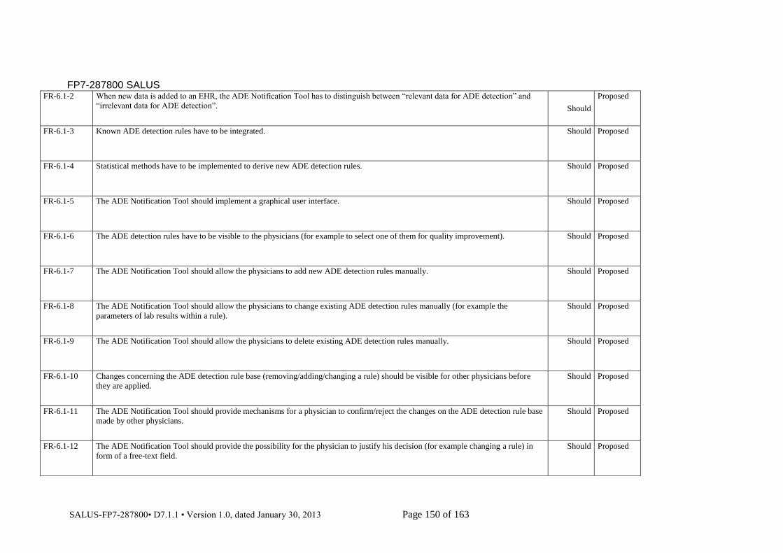
FP7-287800 SALUS
SALUS-FP7-287800• D7.1.1 • Version 1.0, dated January 30, 2013 Page 150 of 163
FR-6.1-2 When new data is added to an EHR, the ADE Notification Tool has to distinguish between “relevant data for ADE detection” and
“irrelevant data for ADE detection”. Should
Proposed
FR-6.1-3 Known ADE detection rules have to be integrated. Should Proposed
FR-6.1-4 Statistical methods have to be implemented to derive new ADE detection rules. Should Proposed
FR-6.1-5 The ADE Notification Tool should implement a graphical user interface. Should Proposed
FR-6.1-6 The ADE detection rules have to be visible to the physicians (for example to select one of them for quality improvement). Should Proposed
FR-6.1-7
The ADE Notification Tool should allow the physicians to add new ADE detection rules manually. Should Proposed
FR-6.1-8 The ADE Notification Tool should allow the physicians to change existing ADE detection rules manually (for example the
parameters of lab results within a rule).
Should Proposed
FR-6.1-9 The ADE Notification Tool should allow the physicians to delete existing ADE detection rules manually. Should Proposed
FR-6.1-10 Changes concerning the ADE detection rule base (removing/adding/changing a rule) should be visible for other physicians before
they are applied.
Should Proposed
FR-6.1-11 The ADE Notification Tool should provide mechanisms for a physician to confirm/reject the changes on the ADE detection rule base
made by other physicians.
Should Proposed
FR-6.1-12 The ADE Notification Tool should provide the possibility for the physician to justify his decision (for example changing a rule) in
form of a free-text field.
Should Proposed

FP7-287800 SALUS
SALUS-FP7-287800• D7.1.1 • Version 1.0, dated January 30, 2013 Page 151 of 163
FR-6.1-13 The ADE Notification Tool should store the physician’s decision on alerts (an ADE is present or not) to evaluate the quality of each
ADE detection rule.
Should Proposed
FR-6.1-14 When a new ADE detection rule is proposed by a physician or derived by the ADE detection, the relevant parameters/information
has to be forwarded to the SALUS ADE Notification Tool expert who implements the new detection rule.
Should Proposed
FR-6.1-15 The ADE Notification Tool should allow the physician to manually decide that an ADE is present. Should Proposed
FR-6.1-16 When the ADE Notification Tool produces an alert this should be presented to the physician accordingly via the graphical user
interface.
Should Proposed
FR-6.1-17 In the case that the ADE Notification Tool detects a new ADR, this should be forwarded to the ICSR Reporting Tool. Should Proposed
Requirements for Safety Analysis Tools
FR-6.2-1 The CSC Tool should be a web based system to support access from different locations
Should
Proposed
FR-6.2-2 The CSC Tool shall use an authentication system to validate that the Safety Analyst can access the interface
Shall
Proposed
FR-6.2-3 The user should be able to specify the statistics that should be visible in the interface
Should
Proposed
FR-6.2-4 The user shall be able to specify the inclusion criteria both for the cases and the comparator population
Shall
Proposed
FR-6.2-5 There shall be a mechanism to translate the inclusion/exclusion choices for the cases and background population specified in queries
into query templates used in the SIL Shall
Proposed

FP7-287800 SALUS
SALUS-FP7-287800• D7.1.1 • Version 1.0, dated January 30, 2013 Page 152 of 163
FR-6.2-6 There should be a mechanism to translate the choices of statistics specified in queries into the query templates used in the SIL
Should
Proposed
FR-6.2-7 There should be a mechanism that ensures that only valid query templates are created
Should
Proposed
FR-6.2-8 The query results shall be presented to the user in the CSC Tool interface in the data model preferred by the Safety analyst in a
pseudonymized way. Shall
Proposed
FR-6.2-9 The patients in the case group shall be possible to transfer into the Patient History Tool
Shall
Proposed
FR-6.2-10 Optional: The patients in the background population group should be possible to transfer into the Patient History Tool
May
Proposed
FR-6.2-11 The TPC Tool should be a web based system to support access from different locations
Should
Proposed
FR-6.2-12 The TPC Tool shall use an authentication system to validate that the Safety Analyst can access the interface Shall Proposed
FR-6.2-13 The user shall be able to specify the inclusion criteria both for the cases and the comparator population Shall Proposed
FR-6.2-14 There shall be a mechanism to translate the inclusion/exclusion choices for the cases and background population specified in queries
into query templates used in the SIL
Shall Proposed
FR-6.2-15 There should be a mechanism that ensures that only valid query templates are created Should Proposed
FR-6.2-16 The results from the query should be presented graphically to the user Should Proposed

FP7-287800 SALUS
SALUS-FP7-287800• D7.1.1 • Version 1.0, dated January 30, 2013 Page 153 of 163
FR-6.2-17 The EA Tool should be a web based system to support access from different locations Should Proposed
FR-6.2-18 The EA Tool shall use an authentication system to validate that the Safety Analyst can access the interface Shall Proposed
FR-6.2-19 The user shall be able to specify the inclusion criteria both for the cases and the comparator population Shall Proposed
FR-6.2-20 There shall be a mechanism to translate the inclusion/exclusion choices for the cases and background population specified in queries
into query templates used in the SIL
Shall Proposed
FR-6.2-21 There should be a mechanism that ensures that only valid query templates are created Should Proposed
FR-6.2-22 The Analyst shall be able to run the selected signal detection algorithms on top of the Analysis Repository to identify emerging
patterns of temporal association between drug prescriptions and medical events for detailed clinical review
Shall Proposed
FR-6.2-23 When necessary use cases “UC-6.2-1 Query Population Data for Safety Analysis” and “UC-6.2-4 Visualizing Patient History” are
triggered.
Should Proposed
FR-6.2-24 The Patient History Tool should be a web based system to support access from different locations Should Proposed
FR-6.2-25 The Patient History Tool shall use an authentication system to validate that the user can access the interface Shall Proposed
FR-6.2-26 The Patient History Tool shall retrieve data from the Safety Analysis Repository Shall Proposed
Interfaces Requirements

FP7-287800 SALUS
SALUS-FP7-287800• D7.1.1 • Version 1.0, dated January 30, 2013 Page 154 of 163
RE-ID Requirement text
Liabilit
y
Status
Requirements of CDE Repository
IR -4.2-1 CDE Repository GUI shall provide interfaces to help and inform the user about the authentication and authorization processes. Shall Proposed
IR -4.2-2 CDE Repository GUI shall provide interfaces to import new UML Models, Content Models and Local Domain Ontologies Shall Proposed
IR -4.2-3 CDE Repository GUI should provide interfaces to present the parsed UML model and the corresponding UML Ontology to the
Domain Expert, and enable him/her to update the ontology Should
Proposed
IR -4.2-4 CDE Repository GUI shall provide interfaces to present the parsed content model and the corresponding Content Model Ontology to
the Domain Expert, and enable him/her to update the ontology Shall
Proposed
IR -4.2-5 CDE Repository GUI shall provide interfaces to present the parsed Local Domain Ontology and the corresponding Content Model
Ontology to the Domain Expert, and enable him/her to update the ontology Shall
Proposed
IR -4.2-6 CDE Repository GUI shall present error messages to inform the Domain Expert when the CDE Repository is not accessible Shall Proposed
IR -4.2-7 CDE Repository GUI shall provide interfaces to annotate the Content Model ontologies Shall Proposed
IR -4.2-8 CDE Repository GUI shall provide interfaces to search CDEs Shall Proposed
IR -4.2-9 CDE Repository GUI shall provide interfaces to filter CDEs. Shall Proposed
IR -4.2-10 CDE Repository GUI shall provide interfaces to browse CDEs. Shall Proposed
IR -4.2-11 CDE Repository GUI should provide interfaces to display the detailed attributes of the selected CDE. Should Proposed
IR -4.2-12 An interface to a Terminology Server should be available to navigate/view/search through the included terminology systems. Should Proposed
IR -4.2-13 CDE Repository GUI shall provide necessary means for exporting the SALUS Core Ontology from the available CDEs Shall Proposed
Requirements of SALUS Semantic Interoperability Layer
IR -4.3-1 System shall provide interfaces to graphically define mapping rules between source ontologies (Content Model Ontologies) and
SALUS Core Ontology Shall
Proposed
IR -4.3-2 System shall provide interfaces to select the source ontologies to be mapped to SALUS Core Ontology Shall Proposed
IR -4.3-3 System shall provide interfaces to define mapping rules between the entities in the source and target ontology Shall Proposed
IR -4.3-4 OPTIONAL. System should provide interfaces to present candidate mapping rules to Domain experts based on annotated Content
Model Ontology May
Proposed
IR -4.3-5 System shall provide interfaces to Domain Experts to review and confirm the overall mapping Shall Proposed
IR -4.3-6 System shall provide an interface to display the content of the terminology system to the Terminology Expert Shall Proposed
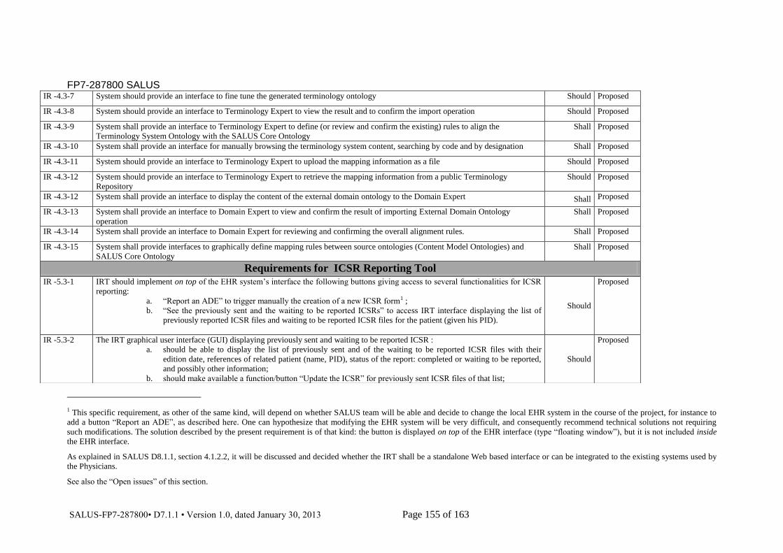
FP7-287800 SALUS
SALUS-FP7-287800• D7.1.1 • Version 1.0, dated January 30, 2013 Page 155 of 163
1 This specific requirement, as other of the same kind, will depend on whether SALUS team will be able and decide to change the local EHR system in the course of the project, for instance to
add a button “Report an ADE”, as described here. One can hypothesize that modifying the EHR system will be very difficult, and consequently recommend technical solutions not requiring
such modifications. The solution described by the present requirement is of that kind: the button is displayed on top of the EHR interface (type “floating window”), but it is not included inside
the EHR interface.
As explained in SALUS D8.1.1, section 4.1.2.2, it will be discussed and decided whether the IRT shall be a standalone Web based interface or can be integrated to the existing systems used by
the Physicians.
See also the “Open issues” of this section.
IR -4.3-7 System should provide an interface to fine tune the generated terminology ontology Should Proposed
IR -4.3-8 System should provide an interface to Terminology Expert to view the result and to confirm the import operation Should Proposed
IR -4.3-9 System shall provide an interface to Terminology Expert to define (or review and confirm the existing) rules to align the
Terminology System Ontology with the SALUS Core Ontology
Shall Proposed
IR -4.3-10 System shall provide an interface for manually browsing the terminology system content, searching by code and by designation Shall Proposed
IR -4.3-11 System should provide an interface to Terminology Expert to upload the mapping information as a file Should Proposed
IR -4.3-12 System should provide an interface to Terminology Expert to retrieve the mapping information from a public Terminology
Repository
Should Proposed
IR -4.3-12 System shall provide an interface to display the content of the external domain ontology to the Domain Expert Shall Proposed
IR -4.3-13 System shall provide an interface to Domain Expert to view and confirm the result of importing External Domain Ontology
operation
Shall Proposed
IR -4.3-14 System shall provide an interface to Domain Expert for reviewing and confirming the overall alignment rules. Shall Proposed
IR -4.3-15 System shall provide interfaces to graphically define mapping rules between source ontologies (Content Model Ontologies) and
SALUS Core Ontology
Shall Proposed
Requirements for ICSR Reporting Tool
IR -5.3-1 IRT should implement on top of the EHR system’s interface the following buttons giving access to several functionalities for ICSR
reporting:
a. “Report an ADE” to trigger manually the creation of a new ICSR form1 ;
b. “See the previously sent and the waiting to be reported ICSRs” to access IRT interface displaying the list of
previously reported ICSR files and waiting to be reported ICSR files for the patient (given his PID).
Should
Proposed
IR -5.3-2 The IRT graphical user interface (GUI) displaying previously sent and waiting to be reported ICSR :
a. should be able to display the list of previously sent and of the waiting to be reported ICSR files with their
edition date, references of related patient (name, PID), status of the report: completed or waiting to be reported,
and possibly other information;
b. should make available a function/button “Update the ICSR” for previously sent ICSR files of that list;
Should
Proposed

FP7-287800 SALUS
SALUS-FP7-287800• D7.1.1 • Version 1.0, dated January 30, 2013 Page 156 of 163
c. should make available a function/button “Finalize and report the ICSR” for ICSR files recorded as “to be
reported later” during a previous session of that list
IR -5.3-3 The IRT GUI for filling the ICSR form should consist of fixed sets of data fields and editable field-texts corresponding to the ICSR
E2B required fields. Should
Proposed
IR -5.3-4 The IRT GUI should distinguish mandatory and optional data fields. Should Proposed
IR -5.3-5 The IRT GUI should have an editable textbox for storing any additional comments and remarks from the HP. Should Proposed
IR -5.3-6 The IRT GUI should have a “Report” button for sending the filled ICSR form to the Local/International Regulatory Authority (after
pseudonymization process). Until all the mandatory fields are not filled and validated by HP, the “Report” button remains inactive.
Once all the mandatory fields are filled and validated by HP, the “Report” button becomes active for sending the ICSR form.
Should Proposed
IR -5.3-7 In case mandatory data fields are not correctly filled or format of the data entered is not correct (date, etc.), the ICSR form is not
sent, and IRT GUI asks the user to correct the wrong entries. Should
Proposed
IR -5.3-8 The IRT GUI should have a button to print the ICSR form in case the HP wants to send a paper version to the Local/International
Regulatory Authority.
Should Proposed
IR -5.3-9 The IRT GUI should implement an interface component to inform the user that the ICSR form has been electronically received by
the Regulatory Authority.
Should Proposed
IR -5.3-10 OPTIONAL. IRT GUI should implement interface components proposing the user to continue the reporting process where it was
interrupted in case of ICSR reporting interruption.
May Proposed
IR -5.3-11 OPTIONAL. IRT GUI should implement interface components allowing the loading of a saved partially filled ICSR form to continue
the reporting process where it was voluntarily stopped
May Proposed
Requirements for SALUS Security and Privacy Services
IR -5.4-1 Audit Repository shall provide interfaces to authorized users to view Audit logs in the repository Shall Proposed
IR -5.4-2 Audit Repository shall provide interfaces to authorized users to sort and filter Audit logs in the repository Shall Proposed
Requirements for ADE Notification Tool
IR -6.1-1 An access to the local EHR database storing clinical data of the patient should be available. Should Proposed
IR -6.1-2 An access to all local and available EHR files should be available for the statistical methods of the ADE Notification Tool through
TIL.
Should Proposed
IR -6.1-3 The new detected ADRs should be forwarded to the ICSR Reporting Tool. Should Proposed
Requirements for Safety Analysis Tools
IR -6.2-1 CSC Tool should use the user authentication system already created in SALUS Should Proposed
IR -6.2-1 CSC Tool should implement functionality to specify the input to create the query template Should Proposed
IR -6.2-2 Should include the possibility to select cases and background population Should Proposed
IR -6.2-3 CSC Tool should include a graphical interface that presents the results from the queries back to the user Should Proposed

FP7-287800 SALUS
SALUS-FP7-287800• D7.1.1 • Version 1.0, dated January 30, 2013 Page 157 of 163
IR -6.2-4 TPC Tool should use the user authentication system already created in SALUS Should Proposed
IR -6.2-5 TPC Tool should implement functionality to specify the input to create the query template: a. Should include the possibility to
select cases and background population
Should Proposed
IR -6.2-6 TPC Tool should include a graphical interface that presents the results from the queries back to the user Should Proposed
IR -6.2-7 Optional: A “Save” button to store results for future review May Proposed
IR -6.2-8 Safety Analyst can logged in to the SALUS Analyst Interface Should Proposed
IR -6.2-9 The Analyst can specify the specifications of the medical datasets to be collected using the SALUS Analyst Interface: The sections
of the EHR extracts of interest are specified and the eligibility criteria specifying the patient population of interest are specified
Should Proposed
IR -6.2-10 The user shall be able to input a patient identifier to see the patient history Shall Proposed
IR -6.2-11 Optional: The user shall be able to sort the results based on dates (like start date of medication) and type of event (Medication,
Diagnosis and Lab Value)
May Proposed
Data Requirements
RE-ID Requirement text Liability Status
Requirements of CDE Repository
DR-4.2-1
The curated CDEs should be represented in an ontology conforming to ISO/IEC 11179 Metadata Registry/Repository Model.
Should Proposed
DR-4.2-2 The Content Model representations should be added to SALUS Semantic Resource Set as instances of a common Content Model
Ontology Should Proposed
DR-4.2-3 Content Model Ontology should allow annotations with terminology system codes
Should Proposed
DR-4.2-4 Content Model Ontology should allow annotations with existing CDEs
Should Proposed

FP7-287800 SALUS
SALUS-FP7-287800• D7.1.1 • Version 1.0, dated January 30, 2013 Page 158 of 163
Requirements of SALUS Semantic Interoperability Layer
DR-4.3-1
The mappings/alignments among source and target ontologies should be represented in a machine processable manner, e.g. as
SPARQL constructs or N3 rules. Should
Proposed
DR-4.3-2 The alignment rules between Terminology System Ontology and the SALUS Core Ontology should be represented in a machine
processable manner, e.g. as SPARQL constructs or N3 rules. Should
Proposed
DR-4.3-3 The mappings between different terminology system codes should be represented in a machine processable manner Should Proposed
DR-4.3-4 The mapping information between two terminology systems to be provided by the Terminology Expert, or to be retrieved from
external terminology repository should be represented in a machine processable format
Should Proposed
DR-4.3-5 The external domain ontology to be included to the SALUS Semantic Resource Set shall be in one of the well accepted
representation standards like RDF, OWL, N3. Shall
Proposed
Requirements for Technical Interoperability Layer Part 1: Subscription Based Interoperability Profiles and Open Source
Toolsets
DR-5.1-1 Data queried from Data Source should be presented in a standardized way like CDA or CCD document type, to be processable by
SALUS ontology. Should Proposed
Requirements for Technical Interoperability Layer Part 2: Query Based Interoperability Profiles and Open Source Toolsets
DR-5.2-1
Data queried from Data Source should be presented in a standardized way like CDA or CCD document type, to be processable by
SALUS ontology.
Should Proposed
Requirements for ICSR Reporting Tool

FP7-287800 SALUS
SALUS-FP7-287800• D7.1.1 • Version 1.0, dated January 30, 2013 Page 159 of 163
2 See ANNEX section for a precise description of data elements required by E2B(R2) specifications.
3 The degree of mapping coverage between the two data model (for instance expressed in percentage of E2B ICSR data elements for which a direct equivalent is described in the data elements
of the data model used by EHR system) that must be achieved for the ICSR prepopulation function to be efficient remains to be quantified. However a basis requirement is that ICSR data
elements that are mandatory for E2B have such a mapping. The same remark applies for terminology mappings.
DR-5.3-1 An access to the local EHR database storing clinical data of the patient should be available2.
Should
Proposed
DR-5.3-1 SIL shall be configured to reconcile the Data Model and the terminology systems used by the ICSR Reporting Tool (in compliance
with the E2B guideline) and the EHR System3. Shall
Proposed
DR-5.3-1 OPTIONAL. Proof-tree generated by the reasoner (i.e. justification trace) for a detected ADE in an EHR under the given ADE rules.
May
Proposed
Requirements for SALUS Security and Privacy Services
DR-5.4-1 Audit Records shall comply with the IHE Audit Trail format
Shall Proposed
Requirements for ADE Notification Tool
DR-6.1-1 A threshold for every ADE detection rule should be implemented and controlled so that it is possible to find ADE detection rules that
always produce wrong alerts Should
Proposed
DR-6.1-2
The following data fields are necessary to get from the EHR-System:
1. - gender: must have
2. - age: must have
3. - lab results: must have
4. - diagnoses: must have (but we need more than just the current diagnosis)
5. - medications (drug, dosage and unit): must have
- symptoms/emergency: must have
Should
Proposed

FP7-287800 SALUS
SALUS-FP7-287800• D7.1.1 • Version 1.0, dated January 30, 2013 Page 160 of 163
DR-6.1-3
OPTIONAL. The following data fields would be nice to get from the EHR-System:
1. weight: nice to have
2. - drug allergies: nice to have
3. - intolerances: nice to have
4. - family history: nice to have
5. - past medical history: nice to have
6. - encounters/episodes of care/stays: nice to have
7. - pregnancy: nice to have
8. - vital signs measurement: nice to have
9. - procedures: nice to have
May Proposed
Requirements for Safety Analysis Tools
DR-6.2-1
It is assumed that a Data warehouse has already established by the participating healthcare institute. SALUS will support tools to
create this DWH if it does not exist.
Should Proposed
Non Functional Requirements
RE-ID Requirement text
Referred use case
Liabilit
y Status
Requirements of CDE Repository
NFR-4.2-1 Processing time Requirements:
i. The import operation for uploading new UML Models/Content Models/Local Domain Ontologies must be
realized in a reasonable time.
ii. The annotation of Content Models must be realized in a reasonable time.
iii. Searching matching CDEs should be realized within a few seconds
Should Proposed
NFR-4.2-2 Space Requirements: (i) A reasonable amount of RAM shall be available for annotating Content Model Ontologies with
Terminology System codes and available CDEs. (ii) A reasonable amount of disk space shall be available for storing CDEs in CDE
Repository.
Shall Proposed

FP7-287800 SALUS
SALUS-FP7-287800• D7.1.1 • Version 1.0, dated January 30, 2013 Page 161 of 163
Requirements of SALUS Semantic Interoperability Layer
NFR-4.4-1 Processing time Requirements:
a. The operation for retrieving terminology systems from external resources must be realized in a reasonable time
b. The operation for uploading external ontologies must be realized in a reasonable time
c. Retrieving clinical data instance to the SIL must be realized in a reasonable time
d. Translating clinical data instance in source format to target format must be realized in a reasonable time
e. Running a semantic query on top of the SIL must be realized in a reasonable time
Shall Proposed
NFR-4.4-1 A reasonable amount of RAM shall be required for SIL. Shall Proposed
Requirements for Technical Interoperability Layer Part 1: Subscription Based Interoperability Profiles and Open Source
Toolsets
NFR-5.1-1 The result of a query should be available within an acceptable time for the physician.
Should Proposed
Requirements for Technical Interoperability Layer Part 2: Query Based Interoperability Profiles and Open Source Toolsets
NFR-5.2-1 The result of a query should be available within an acceptable time for the physician.
Should Proposed
Requirements for ICSR Reporting Tool
NFR-5.3-1 Processing time Requirements: Once the creation of a new ICSR is triggered, the ICSR pre-population process must be realized in a
reasonable time. Time to be decided with end users.
Shall Proposed
NFR-5.3-2 User Requirements: When reporting an ADE through the IRT, the tool should allow the HP to see justification behind the ADE to be
reported.
Should Proposed
NFR-5.3-3 Space Requirements: A reasonable hard-disk space shall be required to store the history/log of all ADEs reported by each HP. Shall Proposed
Requirements for SALUS Security and Privacy Services
NFR-5.4-1 Processing time Requirements:
a. De-identification of a single clinical dataset must be realized in a reasonable time (less than a minute).
b. Re-identification should be realized within a few seconds
Should Proposed

FP7-287800 SALUS
SALUS-FP7-287800• D7.1.1 • Version 1.0, dated January 30, 2013 Page 162 of 163
c. Pseudonymization should be realized within a few seconds
NFR-5.4-2 Space Requirements: (i) A reasonable amount of disk space shall be required for the server to host Audit Repository (ii) A reasonable
amount of RAM shall be required for the server to host De-identification/Pseudonymization services.
Shall Proposed
Requirements for ADE Notification Tool
NFR-6.1-1 The graphical user interface of the ADE Notification Tool should be easy to understand and intuitive to work with due to the fact that
the HP usually are no computer experts.
Should Proposed
NFR-6.1-2 The ADEs should be detected within an appropriate time. Should Proposed
Requirements for Safety Analysis Tools
NFR-6.2-1 Processing time Requirements:
a. Once the query templates are sent the results should be presented to the user within a reasonable time. Time to be
decided.
b. Long running queries should not be stopped due to “time-outs” in the interface
Should Proposed
NFR-6.2-2
Processing time Requirements:
a. The ad hoc selection of cases and background population will probably make for quite long execution times and
as long as the save functionality exists that won’t be a problem.
Should Proposed
NFR-6.2-3 Processing time Requirement:
a. Since a user usually analyses multiple patient histories for a specific issue the processing time is important for
effective patient review. No more than a couple of seconds can be used for each patient
Should Proposed

FP7-287800 SALUS
SALUS-FP7-287800• D7.1.1 • Version 1.0, dated January 30, 2013 Page 163 of 163