Embed Size (px)
Citation preview
8/11/2019 D6M Test Hydraulic System
http://slidepdf.com/reader/full/d6m-test-hydraulic-system 1/21
Testing and AdjustingD6M Track-Type Tractor Hydraulic System
Testing and Adjusting
SMCS - 5050-036
Procedure
1. Move the machine to a smooth horizontal location. Move away from other machines and personnel.Lower all attachments to the ground.
. !ermit only one operator on the machine. "eep all other personnel away from the machine.
3. #ngage the par$ing %ra$e.
&. 'top the engine.
5. Move the hydraulic control levers to all positions so that the pressure in the hydraulic system isreleased.
6. Loosen the filler cap on the hydraulic tan$ so that the pressure in the tan$ is released.
(. )ighten the filler cap on the hydraulic tan$.
*. )he pressure in the system has now %een released and lines or components can %e removed.
+ollow this procedure in order to define a pro%lem with the hydraulic system. +irst, do isual hec$s. /et,do perational hec$s. Lastly, do 2nstrument )ests. )his procedure helps identify hydraulic system pro%lems. nce the pro%lem is defined, go to )rou%leshooting. )he )rou%leshooting 'ection lists the pro%a%le causes of a $nown pro%lem. 'ince there may %e more than one cause for a pro%lem, the)rou%leshooting 'ection may suggest specific inspections or instrument tests %e done. )hese inspections andtests help identify the most pro%a%le causes.
uring a diagnosis of the hydraulic system, remem%er that correct oil flow, temperature, and pressure are
Shutdown SIS
Previous Screen
Product: TRACK-TYPE TRACTORModel: D6M TRACK-TYPE TRACTOR 2RNConfiguration: D6M & D6M !P Trac"-T#$e Tractor% 2RN'-(P
)MAC*+NE, POERED .Y /''6 Engine
Media Number -SENR!"-#$ %ublication Date -#&'#$'$### Date (pdated -&#'&#'$##&
i200'11
Sudden movement of the machine or release of oil under pressure cancause serious injury to persons on or near the machine.
To prevent possible injury, perform the procedure that follos beforetesting and adjusting the hydraulic system.
!4gina 1 de 16M 6M L! )rac$-)ype )ractors 7/00001-8! 9M:;2/#< !=#7# ...
0>0*>01&https?>>1(.0.0.1>siswe%>siswe%>techdoc>techdoc@[email protected]>siswe%>sis...

8/11/2019 D6M Test Hydraulic System
http://slidepdf.com/reader/full/d6m-test-hydraulic-system 2/21
necessary for correct operation. The output of the pump (oil flow) increases with an increase in engine speed(rpm) and decreases when engine speed (rpm) is decreased. Oil pressure is caused by resistance to the flowof oil.
Use 1U-5481 Pressure Gauge Group , 1U-5482 Pressure Adapter Group , 4C-4890 ydraulic Test Group , awatch, a magnet, a thermometer, and a ruler in order to measure the following items.
!. DRIFT RATE in the attachment circuit "ircuit drift is caused by lea#age past cylinder pistons,control $al$e spools, load chec# $al$es, or ma#eup $al$es. %&cessi$e drift can be caused by problemswith one component or e&cessi$e drift can be caused by problems with a combination of components.
'. CYCLE TIME in the attachment circuit "ycle times that are longer than the cycle times shown inthe charts are the result of lea#age, pump wear, andor pump speed. f the basic Operational "hec#sindicate circuit lea#age that is e&cessi$e, perform pressure tests in order to identify the problem.
i!ua" Chec#!
n order to identify hydraulic problems, a $isual inspection of the hydraulic system should be performedfirst. *top the engine and lower the attachments to the ground. n order to remo$e the hydraulic tan# filler
cap, turn the filler cap countercloc#wise. Allow the tan# pressure to escape before remo$ing the filler cap.+a#e the following inspections
!. "hec# all hydraulic oil line connections for damage and lea#s.
'. -ollow all hydraulic oil lines from the attachment to the $al$e. "hec# the lines and connections fordamage and lea#s.
. "hec# the control $al$es for lea#s.
/. "hec# the pump and connections for damage and lea#s.
0. -ollow the pump lines to the tan# and $al$es. "hec# the hydraulic lines and chec# the hydraulic tan#for damage and lea#s.
1. "hec# the oil le$el in the tan#.
2. Use a clear container in order to obtain an oil sample from the tan#. Obtain an oil sample immediatelyafter the machine is stopped. "hec# for air bubbles in the oil sample.
3. 4emo$e the filter element. "hec# for particles in the filter elements. A magnet separates ferrous particles from nonferrous particles.
5. nspect the control lin#age for damaged components.
$%erati&na" Chec#!
'er!&na" In(ur) &r *eath can re!u"t +r&m im%r&%er") chec#in, +&r a"ea#
A".a)! u!e a /&ar* &r car*/&ar* .hen chec#in, +&r a "ea# E!ca%in,+"ui* un*er %re!!ure een a %in h&"e !ie "ea# can %enetrate /&*)ti!!ue cau!in, !eri&u! in(ur) an* %&!!i/"e *eath I+ +"ui* i! in(ecte* int&the !#in it mu!t /e treate* imme*iate") /) a *&ct&r +ami"iar .ith thi!t)%e &+ in(ur)
P6gina ' de '!71+ 8 71+ 9GP Trac#:Type Tractors '4;<<<<!:UP (+A";%) PO=%4%7 ...
'<<3'<!/https!'2.<.<.!siswebsiswebtechdoctechdoc>print>page.?sp@returnurlsiswebsis...
8/11/2019 D6M Test Hydraulic System
http://slidepdf.com/reader/full/d6m-test-hydraulic-system 3/21
The Operational Checks can be used to find leakage in the system. The Operational Checks can be used tofind a bad valve. The Operational Checks can be used to find a bad pump. The speed of the rod movementcan be used to check the condition of the cylinders and the pump.
The oil in the hydraulic system must be the oil which is recommended in the Operation and MaintenanceManual, and at a temperature of 38 to !"C #$%% to $3%&'.
The control valves are in a parallel circuit. The hydraulic pump and the pressure relief valve are common toall circuits. (ach valve section has a load check valve in order to help prevent cylinder drift when the valvespool is first moved.
)elief valves help give protection to system components from e*cessive system pressure. The main relief
valve is also a makeup valve. Makeup valves allow e*tra oil to the cylinders.
Extend and retract each attachment cylinder several times.
$. Observe the attachment cylinder as the cylinder e*tends and as the cylinder retracts. Movement must be uniform and regular.
+. isten for noise from the pump.
3. isten for the sound of the relief valve. The relief valve must not open e*cept when the attachmentcylinders are fully e*tended or retracted.
The pressure setting of the relief valve can lower the performance of the machine. - high pressuresetting causes a reduction in the life of hoses and other parts of the system.
". -llow the attachment cylinders to travel full stroke in each direction.
!. ut each control valve in /O0 while the attachment is off the ground. 1atch for e*cessive cylinderrod drift.
Cylinder drift is caused by leakage through piston seals, control valves, check valves, makeup valvesand2or too much clearance between the spool and the valve body.
Drift Test for Lift Cylinder
The drift rates change with different conditions of the hydraulic components. The drift rates change withmachine operation, hydraulic oil temperature, etc. efore you measure drift of the cylinder rod, the cylindersmust be e*tended at least five times.
Measure lift cylinder rod drift by using the following procedure:
$. Check hydraulic oil temperature.
+. ift the bulldo4er until the cutting edge is appro*imately +!" mm #$%.% inch' off the ground. 1ith thelift control lever in the /O0 position, stop the engine.
3. Measure the distance and check the time that the cylinders e*tend. Compare the values to the values inthe chart.
Mae reference to !"#$%$& on first page of Testing "nd "d'ustingsection.
5gina 3 de +$06M 7 06M Track9Type Tractors +):%%%%$9; #M-C/<:(' O1()(0 ...
+%2%82+%$"https=22$+>.%.%.$2sisweb2sisweb2techdoc2techdoc?print?page.@spAreturnurlB2sisweb2sis...

8/11/2019 D6M Test Hydraulic System
http://slidepdf.com/reader/full/d6m-test-hydraulic-system 4/21
$ote: The drift distances in the chart are for new machines.
Lift cylinder rod drift is caused by the following occurrences:
oose oil line connections and condition of the oil hoses between the control valve and the rod ends ofthe lift cylinders.
eakage around the piston seals in the lift cylinders.
There is leakage in the control valve, because of a worn valve section and a worn spool valve, or because of a unseated check valve.
Drift Test for Tilt Cylinder
Measure tilt cylinder rod drift by using the following procedure:
$. Check hydraulic oil temperature.
+. &ully retract the tilt cylinder.
3. ower the bulldo4er in order to lift the front idlers off the ground. Move the control levers to the/O0 position and stop the engine.
". Measure the distance and check the time that the cylinder e*tends. Compare these values to the valuesin the chart.
$ote: The drift distances in the chart are for new machines.
Tilt cylinder rod drift is caused by the following occurrences:
oose oil line connections and condition of the oil hoses between the control valve and the rod end ofthe tilt cylinders.
eakage around the piston seals in the tilt cylinders.
Table $
Lift Cylinder Drift
Oil Temperature38 to "C #$%% to $+%
&'
" to 66C #$+% to $!%
&'
Over 66C #Over $!%
&'
Ma*imum -llowable0rift 3+ mm #$.3 inch' 3+ mm #$.3 inch' 3+ mm #$.3 inch'
Time <nterval #minutes' !.% +.> $.>
Table +
Tilt Cylinder Drift
Oil Temperature38 to "C #$%% to $+%
&'" to 66C #$+% to $!%
&'Over 66C #Over $!%
&'
Ma*imum -llowable0rift $3 mm #%.! inch' $3 mm #%.! inch' $3 mm #%.! inch'
Time <nterval #minutes' !.% +.> $.>
5gina " de +$06M 7 06M Track9Type Tractors +):%%%%$9; #M-C/<:(' O1()(0 ...
+%2%82+%$"https=22$+>.%.%.$2sisweb2sisweb2techdoc2techdoc?print?page.@spAreturnurlB2sisweb2sis...

8/11/2019 D6M Test Hydraulic System
http://slidepdf.com/reader/full/d6m-test-hydraulic-system 5/21
There is leakage in the control valve (worn valve section and worn spool valve).
Drift Test for Ripper Cylinder
Measure ripper cylinder rod drift by using the following procedure:
1. Check hydraulic oil temperature.
2. Lift the ripper so that the ripper teeth are approximately 2! mm (1"." inch) off the ground. #ove theripper control lever to the $%L& position. 'top the engine.
. #easure the distance and check the time that the cylinder extends. Compare these values to the valuesin the chart.
Note: The drift distances in the chart are for new machines.
Ripper cylinder rod drift is caused by the following occurrences:
Loose oil line connections or damaged oil lines with oil leaks.
Leakage around the piston seals in the ripper cylinder.
There is leakage in the control valve (worn valve section and worn spool valve).
Speed Tests for Hydraulic Cylinders
The oil in the system must e the oil which is recommended in %peration and #aintenance #anual* and at atemperature of +, - ,C (1!, - ,/). 0ll speed tests should e made with the engine speed at $$&L3.
dentify the speed of each cylinder. Compare these values to the values in the chart. 34ual values indicatenormal circuit operation.
f the speed of a cylinder is too slow* check that circuit for cylinder drift.
5aise the ulldo6er and check the time. Compare the values to the values in the chart. Tilt the ulldo6er ineach direction and check the time. 0ngle the ulldo6er in each direction. Compare the values to the values inthe chart.
Tale
Ripper Cylinder Drift
%il Temperature7 to !,C (1"" to 12",
/)! to ++,C (12" to 1",
/)%ver ++,C (%ver 1",
/)
#aximum 0llowale&rift 2 mm (1." inch) 2 mm (1." inch) 2 mm (1." inch)
Time nterval (minutes) ." 2.8 1.8
Tale !
Bulldozer ift Cylinder Speed Test Speed !seconds"
9 :ulldo6er' :ulldo6er0 :ulldo6er
50'3 (ground level to maximum height) 2. - ".22." - ".22." - ".2
9;gina de 21&+# < &+# L9 Track=Type Tractors 25>""""1=?9 (#0C$>3) 9%@353& ...
2"A"7A2"1!httpsBAA128.".".1AsisweAsisweAtechdocAtechdocprintpage.DspEreturnurlFAsisweAsis...

8/11/2019 D6M Test Hydraulic System
http://slidepdf.com/reader/full/d6m-test-hydraulic-system 6/21
Resolver Network
A resolver is a check valve. The network compares two pressures. The lowest pressure of the two pressuresis blocked. The highest pressure of the two pressures or signals goes to the next component in the resolvernetwork.
5S 8' Bulldoer !.5 " #.!
Table 5
Bulldozer Tilt Cylinder Speed Test Speed (seconds)
5$ Bulldoer T%&T full( retracted to full( extended) !.* " #.!
5$ Bulldoer T%&T full( extended to full( retracted) !.5 " #.!
Table +
Bulldozer Angle Cylinder Speed Test Speed (seconds)
5$ Bulldoer
A,-& full left to full right)
/./ " #.!
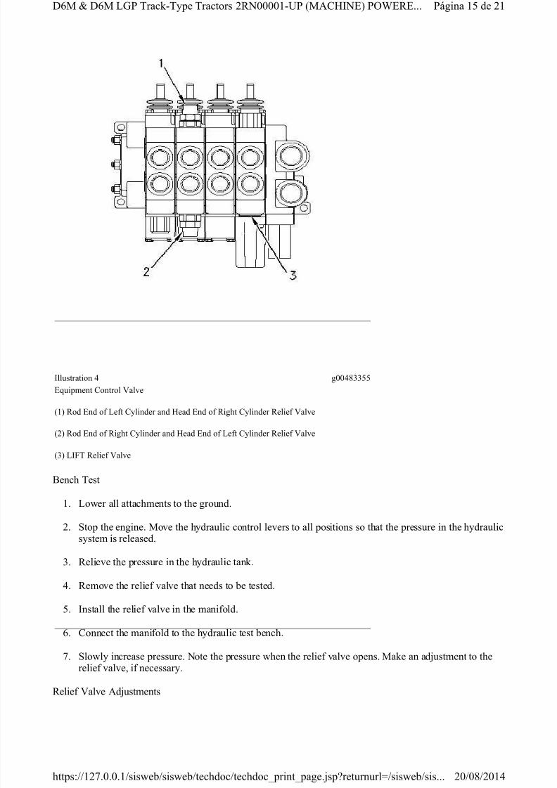
%llustration * g##08*#1#
T(pical 2ontrol 3alve
$4gina + de !*+6 7 +6 &-$ TrackT(pe Tractors !9,####*:$ 6A2;%,) $<=9 ...
!#>#8>!#*0https?>>*!1.#.#.*>sisweb>sisweb>techdoc>techdoc@[email protected]>sisweb>sis...
8/11/2019 D6M Test Hydraulic System
http://slidepdf.com/reader/full/d6m-test-hydraulic-system 7/21
There are two resolvers per control valve. Primary resolver (1) compares rod to head cylinder pressures.Secondary resolver (2) compares the highest primary signal in the control valve to the highest primary signal
in the next control valve. The secondary resolvers are arranged in series.
The resolvers can be affected by debris worn seals worn seats or missing balls.
Troubleshooting the Resolver Network
The signal networ! can be easily chec!ed. Start the engine and warm up the hydraulic oil. "un the engine at#$% &'# for this chec!. onnect a *++++ !Pa (,*-1.2 psi) pressure gauge to the signal line pressure tap.$perate each control lever in the following order
1. "ipper
2. /ngle
*. Tilt
,. #ift
Put each attachment under a load. %atch the pressure gauge. 0aximum system pressure should be seen forall circuits. y using the pressure gauge small lea!age problems can be detected.
Secondary Resolvers (Two or more valve sections)
&f two or more control valves next to each other fail to wor! normally the problem may be in the secondary
resolver of the first control valve that is closest to the pump supply. The secondary resolver of this controlvalve is allowing signal pressure from any other control valve to lea! through a signal passage to the tan!.
$ne of the following conditions could also cause one of the control valves to fail
the ball is missing.
there is debris that is preventing the ball from seating properly.
the seal is missing or there is lea!age when multiple valves malfunction.
$perate the malfunctioning valve that is farthest from the pump. Proceed through the valves in the followingorder
1. "ipper
2. /ngle
*. Tilt
,. #ift
The valve that operates two attachments at the same time contains a failed secondary resolver. The farthest
valve is sending a signal and the failed valve is also sending a signal. %hen the two pressures are comparedat the failed resolver the lea!age has no impact on the signal. The incorrect pressure goes to the pump andthe signal has no effect on the flow control valve.
(1) Primary "esolver
(2) Secondary "esolver
Pgina 3 de 21'40 5 '40 #6P Trac!7Type Tractors 2"8++++179P (0/:&8) P$%"' ...
2+;+<;2+1,https;;123.+.+.1;sisweb;sisweb;techdoc;techdoc=print=page.>sp?returnurl@;sisweb;sis...

8/11/2019 D6M Test Hydraulic System
http://slidepdf.com/reader/full/d6m-test-hydraulic-system 8/21
Primary Resolver versus Secondary Resolver
If a valve section fails to work in at least one direction, the primary resolver or the secondary resolver in thatcontrol valve may be bad. To locate the bad resolver, perform the following check.
Stall the attachment that is farthest away from the pump. This will force the ball in the secondary resolver toseat on the side away from the drain. This eliminates the possibility of a leak on the drain side of the
secondary resolver. Operate the suspect valve and stall the other attachment. If the problem is not correctedin the original valve, the primary resolver may be bad.
If the primary resolver is bad, the pressure loss is affecting the operation of the flow control spool in thevalve body. The force that is needed to open the valve completely is insufficient. Therefore, the attachmenthas a slower response.
Normally, if an attachment is slow in both directions, the problem is usually in the secondary resolver. If anattachment is slow in one direction, the problem is typically caused by a bad primary resolver.
A malfunctioning valve section might be caused by one of the following items
misad!usted linkage
pressure reducing valve spring
incorrectly installed flow control spool
bad line relief valve or makeup valve
Note: If there is debris in the system, the system should be flushed by removing the balls from the secondaryresolvers and operating the e"uipment. #nough flow will be supplied in order to flush the debris into thehydraulic tank.
Pump Efficiency Test
A pump efficiency test is designed to tell if a pump is operating within design parameters. A pumpefficiency test should be performed if cylinder cycle time is slow.
$or any pump test, the pump flow that is measured at %&' k(a )*'' psi+ is larger than the pump flow that ismeasured at %&'' k(a )*''' psi+ at the same rpm.
The difference between the pump flow of two operating pressures is the flow loss.
Note: The oil in the hydraulic system must be the oil which is recommended in the Operation andaintenance anual. The oil must be at a temperature of %- / 01 )*2& / -$+.
$low loss is measured by using the following procedure
Make reference to WARNING on first pae of Testin And Ad!ustinsection"
Table 3
(ump flow at%&' k(a )*'' psi+ 4*3.% 56min )-3.- 7S gpm+
(8gina 9 de 4*:% ; :% 5<( Track=Type Tractors 4>N''''*=7( )A1?IN#+ (O@#>#: ...
4'6'964'*2https66*43.'.'.*6sisweb6sisweb6techdoc6techdocprintpage.!spBreturnurlC6sisweb6sis...

8/11/2019 D6M Test Hydraulic System
http://slidepdf.com/reader/full/d6m-test-hydraulic-system 9/21
Flow loss is used as a measure of pump performance when flow loss is expressed as a percent of pump flow.
Percent of flow loss is found in the following example:
See the following example:
If the percent of flow loss is more than 10 percent, pump performance is not good enough.
*The numers in the ao!e example are for illustration purposes. The numers are not !alues for an"specific pump or pump condition. #efer to Specifications, S$%#&'1(, for pump flow at )0 +Pa 100 psi-and for pump flow at )00 +Pa 1000 psi-.
Test on Machine
Install a flow meter. #un the engine at I/ I$. 2easure the pump flow at )0 +Pa 100 psi- and at)00 +Pa 1000 psi-. 3se these !alues in Formula I.
Formula I
Test on Bench
If the test ench can e run at )00 +Pa 1000 psi- and at full pump speed, find the percent of flow loss "using Formula I.
If the test ench cannot e run at )00 +Pa 1000 psi- at full pump speed, run the pump shaft at 1000 rpm.2easure the pump flow at )0 +Pa 100 psi- and at )00 +Pa 1000 psi-. 3se these !alues in the top part ofFormula II. For the ottom part of the formula, run the pump shaft at '000 rpm. 2easure the pump flow at
Pump flow at)00 +Pa 1000 psi- 41).( 5min &'.0 3S gpm-
Flow loss'0.( 5min &.& 3S gpm-
Tale (
5min 3S gpm- of flow loss
6 100
7 Percent of flow loss
Pump flow at)0 +Pa 100 psi-
Tale
'0.( 5min &.& 3S gpm- 6 100 7 .)8
'19.) &9.&-
Tale 105min 3S gpm- at )0 +Pa 100 psi- 4 5min 3S gpm- at )00 +Pa1000 psi- 6 100 7 Percent of flow loss
5min 3S gpm- at)0 +Pa 100 psi-
Pgina de '1)2 ; )2 /P Trac+4T"pe Tractors '#%0000143P 2<=I%$- P>?$#$ ...
'050(5'01@https:551'9.0.0.15siswe5siswe5techdoc5techdocAprintApage.BspCreturnurl75siswe5sis...

8/11/2019 D6M Test Hydraulic System
http://slidepdf.com/reader/full/d6m-test-hydraulic-system 10/21

8/11/2019 D6M Test Hydraulic System
http://slidepdf.com/reader/full/d6m-test-hydraulic-system 11/21
Note: In order to identify the signal pressure, remove the plug at signal pressure tap (3) . Install a 8T-2352Face Seal Tee , 6V-3965 Nipple Assemly and 3J-1907 !"#ing Seal . Install the plug that $as removedfrom signal pressure tap (3) into the other end of the 8T-2352 Face Seal Tee .
Pump Discharge Pressure Tests
%ump discharge pressures are &no$n values that can e found under t$o specific conditions. The first
condition is lo$ pressure standy. The second condition is the high pressure stall.
'o$ %ressure Standy Test %rocedure
. #emove the plug and install a to * &%a ( to + psi) pressure gauge in pump pressure tap (-) .
-. Start the engine and run the engine at I/ I0'1.
3. 'eave all control levers in the !'0 position.
*. The pressure reading must e aout -2+ &%a (-.+ psi). 'o$ pressure standy is appro4imately 3*+&%a (+. psi) higher than margin pressure. 5argin pressure is 6- 7 &%a (-*.+ 7 *.+ psi).
+. Ad8ustments to pump output should not e made ased only on the results of this test. Instead, if theresults are not acceptale, the margin pressure test should also e run.
igh Pressure !ta"" Test Proce#ure
. 'o$er all attachments to the ground.
-. Stop the engine. 5ove the hydraulic control levers to all positions so that the pressure in the hydraulicsystem is released.
3. #elieve the pressure in the hydraulic tan&.
*. Install a to - &%a ( to * psi) pressure gauge at pump pressure tap (-) .
+. Start the engine and run the engine at I/ I0'1.
2. 5ove all control levers (one at a time) in oth directions in order to initiate a stall condition. 0o not&eep any control lever in a stalled position for more than seconds. 0o not return to a stalled position $ithin 3 seconds of the prior stalled position.
6. %ressure reading must e -* 7 3+ &%a (32 7 + psi).
Note: If the pressure reading is too high or too lo$, the pressure compensator valve needs to ead8usted.
$argi% Pressure Test
Tale -
Too"s Nee#e#:
8T-5320&'-&890 ydraulic Test /roup
Tale 3Too"s Nee#e#:
%9gina de -025 : 025 '/% Trac&"Type Tractors -#N";% (5A<IN1) %!=1#1...
->>-*https?>>-6...>sis$e>sis$e>techdoc>techdoc@[email protected]>sis$e>sis...

8/11/2019 D6M Test Hydraulic System
http://slidepdf.com/reader/full/d6m-test-hydraulic-system 12/21
1. Lower all attachments to the ground.
2. Stop the engine. Move the hydraulic control levers to all positions so that the pressure in the hydraulicsystem is released.
3. Relieve the pressure in the hydraulic tank.
4. Remove the side cover from the right side of the machine.
. Remove the plug and install a 6V-3965 !ipple "ssem#ly with a 3J-1907 $%Ring Seal at pump pressure tap &2' .
(. Remove the plug and install a 8T-2352 )ace Seal *ee at signal pressure tap &3' . +nstall the plug thatwas removed from tap &3' to one end of the 8T-2352 )ace Seal *ee . +nstall a 6V-3965 !ipple"ssem#ly with a 3J-1907 $%Ring Seal to the other end of the 8T-2352 )ace Seal *ee . +nstall the pressure side of the pressure gauge to the nipple.
,. Start the engine and run the engine at -+- +/L0. heck for leaks.
. arm up the hydraulic oil. heck for leaks.
. Move the #ulldo5er control lever to a position #etween the -$L/ and R"+S0 positions. Read the
pressure on the gauge. *his is the margin pressure or the difference #etween pump discharge pressureand the signal pressure from the control valve. *he margin pressure should #e 1,26 7 166 k8a &24.7 14. psi'.
16. +f margin pressure is not correct9 ad:ust the flow compensator spool.
Note: Recheck the margin pressure after the flow compensator spool has #een ad:usted.
*he high pressure stall test will tell if pressure compensator valve &(' needs to #e ad:usted. *he margin pressure test and;or the low pressure stand#y test will also tell if flow compensator valve &(' needs to #ead:usted.
Adjustment Procedures for Comens!tor V!"#e
1$-5796 8ressure /ifferential auge roup
8T-2352 )ace Seal *ee
6V-3965 )itting
3J-1907 $%Ring Seal
8<gina 12 de 21/(M = /(M L8 *rack%*ype *ractors 2R!66661%>8 &M"-+!0' 8$0R0...
26;6;2614https?;;12,.6.6.1;siswe#;siswe#;techdoc;techdoc@print@page.:spAreturnurlB;siswe#;sis...

8/11/2019 D6M Test Hydraulic System
http://slidepdf.com/reader/full/d6m-test-hydraulic-system 13/21
Pressure Compensator Spool Adjustment
Adjustments to the pressure compensator valve can be made on the machine.
1. Lower all attachments to the ground.
2. Stop the engine. Move the hydraulic control levers to all positions so that the pressure in the hydraulicsystem is released.
. Loosen loc!nut "#$ .
%. &urn adjustment screw "'$ cloc!wise in order to increase the pressure setting. &urn adjustment screw"'$ countercloc!wise in order to decrease the pressure setting.
Note: &urn adjustment screw "'$ countercloc!wise past the desired pressure setting. &hen( turnadjustment screw "'$ cloc!wise to the correct pressure setting. &his method o) adjusting the pressuresetting eliminates any movement in the threads.
*. +epeat the high pressure stall test in order to veri)y that the pressure setting is 2%#,, - *, !Pa ",,- *, psi$.
. /nce the pressure is adjusted( tighten loc!nut "#$ .
0low Compensator Spool Adjustment
llustration g,,%##,
Compensator alve
"%$ 0low Compensator Adjustment Screw
"*$ Loc!nut
"$ 0low Compensator Spool
"'$ Pressure Compensator Adjustment Screw
"#$ Spring
"3$ Pressure Compensator Spool
P4gina 1 de 215M 6 5M L7P &rac!8&ype &ractors 2+9,,,,18:P "MAC;9<$ P/=<+<...
2,>,#>2,1%https?>>12'.,.,.1>sisweb>sisweb>techdoc>techdoc@[email protected]>sisweb>sis...

8/11/2019 D6M Test Hydraulic System
http://slidepdf.com/reader/full/d6m-test-hydraulic-system 14/21
Adjustments to the )low compensator valve can be made on the machine.
1. Lower all attachments to the ground.
2. Stop the engine. Move the hydraulic control levers to all positions so that the pressure in the hydraulicsystem is released.
. Loosen loc!nut "*$ .
%. &urn adjustment screw "%$ cloc!wise in order to increase the pressure setting. &urn adjustment screw"%$ countercloc!wise in order to decrease the pressure setting.
Note: &urn adjustment screw "%$ countercloc!wise past the desired pressure setting. &hen( turnadjustment screw "%$ cloc!wise to the correct pressure setting. &his method o) adjusting the pressuresetting eliminates any movement in the threads.
*. +epeat the margin pressure test and the low pressure standby test.
. /nce the pressure is adjusted( tighten loc!nut "*$ .
Relief Valves
&here is no main line relie) valve. &he pressure compensator valve acts as a line relie) valve in order to limitsystem pressure.
&he setting )or the high pressure stall test is 2%#,, - *, !Pa ",, - *, psi$.
&he pressure compensator can be chec!ed on the machine by running the high pressure stall test.
&he correct pressure setting )or the angle relie) valves is %%, - *, !Pa "%33#.1 - *,.# psi$.
&he correct pressure setting )or the other relie) valves is 2%2,, - *, !Pa "*1,., - *,.# psi$.
Make reference to WARNING on first page of Testing And Adjustingsection.
&able 1%
Tools Needed:
3!"##$ <lectric ;ydraulic Pump
1:8*21 Mani)old
P4gina 1% de 215M 6 5M L7P &rac!8&ype &ractors 2+9,,,,18:P "MAC;9<$ P/=<+<...
2,>,#>2,1%https?>>12'.,.,.1>sisweb>sisweb>techdoc>techdoc@[email protected]>sisweb>sis...
8/11/2019 D6M Test Hydraulic System
http://slidepdf.com/reader/full/d6m-test-hydraulic-system 15/21

8/11/2019 D6M Test Hydraulic System
http://slidepdf.com/reader/full/d6m-test-hydraulic-system 16/21
1. Remove protective cap (4) .
2. Loosen locknut (5) .
3. Turn adjustment screw (6) clockwise or an increase in t!e pressure settin". Turn adjustment screw (6)counterclockwise or a decrease in t!e pressure settin".
4. #ter screw (6) is turned or an adjustment$ ti"!ten locknut (5) and test t!e adjustment.
5. %nstall cap (4) ater t!e settin" is correct.
Troubleshooting
Problem List
Problem List for the Hydraulic Pump and the Hydraulic System
1. (A) T!e temperature o t!e oil is too !i"!.
2. (A) T!e pump makes unusual noise. T!e c&linder rods do not move smoot!l& and t!ere are air 'u''lesin t!e oil.
3. (A) T!ere is a lar"e amount o air in t!e oil.
4. (A) T!e settin" or low pressure stand'& is too low.
5. (A) T!e settin" or low pressure stand'& is too !i"!.
6. (A) T!e mar"in pressure is too low.
%llustration 5 "4335*
T&pical +om'ination Line Relie and ,akeup -alve
(4) +ap
(5) Locknut
(6) #djustment crew
/0"ina 16 de 216, 6, L/ TrackT&pe Tractors 2R1/ (,#+7%8) /9:8R8...
2;;214!ttps<;;12=...1;siswe';siswe';tec!doc;tec!doc>print>pa"e.jsp?returnurl@;siswe';sis...

8/11/2019 D6M Test Hydraulic System
http://slidepdf.com/reader/full/d6m-test-hydraulic-system 17/21
7. (A) The margin pressure is too high.
8. (A) Pump discharge pressure is too high.
9. (A) Pump discharge pressure is too low.
10. (A) There is a pause before pressure is reached in all circuits.
11. (A) Signal pressure is not zero when all valves are in the !"# position.
Problem List for the Equipment System
1. (B) $n% attachment moves with the control levers in the !"# position.
&. (B) The control stem on a valve will not shift into the bod%.
'. (B) The attachments e(hibit e(cessive drift.
). (B) The attachments droop when the attachments are raised.
*. (B) The c%cle times of the attachments are too slow.
+. (B) The bulldozer blade moves upward. This occurs with the control lever in the !"# position.
7. (B) The c%cle times of the attachments are too fast.
8. (B) There is too long of a pause at ground level before the bulldozer starts to raise.
9. (B) The line relief valves are too nois%.
Probable Cause List
Probable Cause List for the Hydraulic Pump and the Hydraulic System
Problem 1 (A)
The temperature of the oil is too high.
Probable Cause
1. ,rong oil viscosit%
&. -(cessive wear in the pump
'. estriction in an oil passage
). -(cessive load on the s%stem
*. !il aeration
+. "ow oil level
7. ,rong setting of flow compensator valve
8. igh outside air temperature
Problem ! (A)
P/gina 17 de &1#+ #+ "2P Trac34T%pe Tractors &50000146P $5-: P!,--...
&0;08;&01)https<;;1&7.0.0.1;sisweb;sisweb;techdoc;techdoc=print=page.>sp?returnurl@;sisweb;sis...

8/11/2019 D6M Test Hydraulic System
http://slidepdf.com/reader/full/d6m-test-hydraulic-system 18/21
The pump makes unusual noise. The cylinder rods do not move smoothly and there are air bubbles in the oil.
Probable Cause
1. Wrong oil viscosity
2. Oil aeration
3. Excessive wear in the pump
. !ow oil level
Problem 3. (A)
There is a large amount o" air in the oil.
Probable Cause
1. Oil aeration
2. !ow oil level
3. !eakage around cylinder seals
Problem 4. (A)
The setting "or low pressure standby is too low.
Probable Cause
1. Wrong setting o" "low compensator valve
2. #roken spring in "low compensator valve
3. $al"unctioning pump
. Wrong setting o" pressure compensator valve
%. #roken spring in pressure compensator valve
Problem 5. (A)
The setting "or low pressure standby is too high.
Probable Cause
1. Wrong setting o" "low compensator valve
2. &ignal pressure above 'ero
Problem 6. (A)
The margin pressure is too low.
Probable Cause
1. Wrong setting o" "low compensator valve
()gina 1* de 21+,$ - +,$ !( Track/Type Tractors 201/( 4$5678E9 (OWE0E...
2:*:21https;::12<...1:sisweb:sisweb:techdoc:techdoc=print=page.>sp?returnurl@:sisweb:sis...

8/11/2019 D6M Test Hydraulic System
http://slidepdf.com/reader/full/d6m-test-hydraulic-system 19/21
2. !eak in the signal network
Problem 7. (A)
The margin pressure is too high.
Probable Cause
1. Wrong setting o" "low compensator valve
Problem 8. (A)
(ump discharge pressure is too high.
Probable Cause
1. Wrong setting o" pressure compensator valve
2. $al"unctioning pressure compensator valve
3. $al"unctioning pump
Problem 9. (A)
(ump discharge pressure is too low.
Probable Cause
1. Wrong setting o" pressure compensator valve
2. #roken spring in pressure compensator valve
3. !ow setting o" line relie" valve
. !eak in the signal network
Problem 10. (A)
There is a pause be"ore pressure is reached in all circuits.
Probable Cause
1. 5ir in the signal network
2. +irt or debris in resolver
Problem 11. (A)
&ignal pressure is not 'ero when all valves are in the 7O!+ position.
Probable Cause
1. 5ctivated control lever
2. (ressure in signal network
Probable Cause List for the Equipment Sstem
()gina 1A de 21+,$ - +,$ !( Track/Type Tractors 201/( 4$5678E9 (OWE0E...
2:*:21https;::12<...1:sisweb:sisweb:techdoc:techdoc=print=page.>sp?returnurl@:sisweb:sis...

8/11/2019 D6M Test Hydraulic System
http://slidepdf.com/reader/full/d6m-test-hydraulic-system 20/21
Problem 1. (!)
5ny attachment moves with the control levers in the 7O!+ position.
Probable Cause
1. Excessive wear in the control valve
2. Wear in the cylinders
3. !eakage between the valve and the cylinders
Problem ". (!)
The control stem on a valve will not shi"t into the body.
Probable Cause
1. 6ontamination in the end housing
Problem #. (!)
There is excessive dri"t in the attachments.
Probable Cause
1. Wear in the cylinders
2. !eakage around a makeup valve
3. 8ncorrect position o" spool in the main control valve
. Excessive wear in the control valve
Problem $. (!)
The attachments droop when the attachments are raised.
Probable Cause
1. 5ir in the signal network
2. +irt or debris in the resolver
3. Wrong setting o" "low compensator valve
. #roken spring in "low compensator valve
Probable Cause
Problem %. (!)
The cycle times o" the attachments are too slow.
Probable Cause
1. !eakage in the signal network
()gina 2 de 21+,$ - +,$ !( Track/Type Tractors 201/( 4$5678E9 (OWE0E...
2:*:21https;::12<...1:sisweb:sisweb:techdoc:techdoc=print=page.>sp?returnurl@:sisweb:sis...

8/11/2019 D6M Test Hydraulic System
http://slidepdf.com/reader/full/d6m-test-hydraulic-system 21/21
2. Incorrect setting of margin pressure
3. Malfunctioning pump
Problem 6. (B)
The bulldozer blade moves upward. This occurs with the control lever in the HOL position.
!. Malfunctioning ma"eup valve
Problem 7. (B)
The c#cle times of the attachments are too fast.
Probable Cause
!. Incorrect setting of margin pressure
Problem 8. (B)
There is too long of a pause at ground level before the bulldozer starts to raise.
Probable Cause
!. $tic"ing restrictor spool
Problem 9. (B)
The line relief valves are too nois#.
Probable Cause
!. Low setting of line relief valve
2. %ro"en spring in line relief valve
3. &rong setting of pressure compensator valve
Copyright 1993 - 2014 Caterpillar Inc.
All Rights Reserved.Private Netor! "or #I# $icensees.
%ed A&g 20 1'(14(20 )#* 2014
'(gina 2! de 2!)M * )M L+' Trac",T#pe Tractors 2-////!,0' 1MHI45 'O&4-4...