Embed Size (px)
Citation preview

A New and Superior Ultrafine Cementitious Grout
Ernst H. Ahrens'
Abstract
Sealing fractures in nuclear waste repositories concerns all programs investigating deep burial as a means of disposal. Because the most likely mechanism for contaminant migration is by dissolution and movement through groundwater, sealing programs are seeking low-viscosity sealants that are chemically, mineralogically, and physically compatible with the host rock. This paper presents the results of collaborative work directed by Sandia National Laboratories (SNL) and supported by Whiteshell Laboratories, operated by Atomic Energy of Canada, Ltd. The work was undertaken in support of the Waste Isolation Pilot Plant (WIPP), an underground nuclear waste repository located in a salt formation east of Carlsbad, NM. This effort addresses the technology associated with long-term isolation of nuclear waste in a natural salt medium. The work presented is part of the WIPP plugging and sealing program, specifically the development and optimization of an uItrafine cementitious grout that can be injected to lower excessive, strain-induced hydraulic conductivity in the fractured rock termed the Disturbed Rock Zone (DRZ) surrounding underground excavations. Innovative equipment and procedures employed in the laboratory produced a usable cement-based grout; 90% of the particles were smaller than 8 microns and the average particle size was 4 microns (Ahrens et al., 1996). The process involved simultaneous wet pulverization and mixing. The grout was used for a successful in situ test underground at the WIPP. Injection of grout sealed microfractures as small as 6 microns (and in one rare instance, 3 microns) and lowered the gas transmissivity of the DRZ by up to three orders of magnitude. Following the WIPP test, additional work produced an improved version of the grout containing particles 90% smaller than 5 microns and averaging 2 microns. This grout will be produced in dry form, ready for the mixer.
DISTRiBURON OF THIS D6CUMENT ts ' Senior Member of Technical Staff, Sandia National Laboratories, Albuquerque, NM, USA
1 Ahrens

DISCLAIMER
This report was prepared as an account of work sponsored by an agency of the United States Government. Neither the United States Government nor any agency thereof, nor any of their employees, make any warranty, express or implied, or assumes any legal liabili- ty or mpomibility for the accuracy, completeness, or usefulness of any information, appa- ratus, product, or process disdosed, or represents that its use wwld not infringe privately owned rights. Reference herein to any specific commercial product, process, or service by trade name, trademark, manufacturer, or otherwise does not necessarily constitate or imply its endorsement, recommendation, or favoring by the United States Government or any agency thereof. The views and opinions of authors expressed herein do not necessar- ily state or reflect those of the United States Government or any agency thereof.

Portions of this document may be illegible in electronic image products. Images are produced from the best available original dOCUment
Introduction
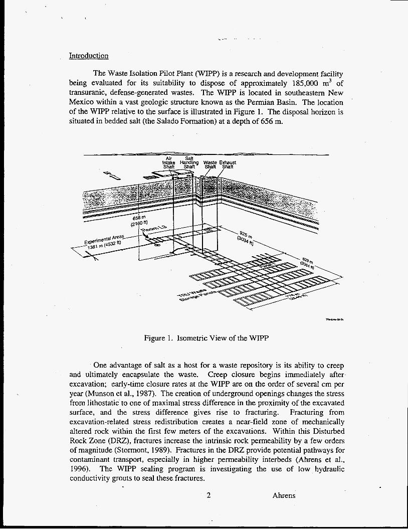
The Waste Isolation Pilot Plant (WIPP) is a research and development facility being evaluated for its suitability to dispose of approximately 185,000 m3 of transuranic, defense-generated wastes. The WIPP is located in southeastern New Mexico within a vast geologic structure known as the Permian Basin. The location of the W P relative to the surface is illustrated in Figure 1. The disposal horizon is situated in bedded salt (the Salado Formation) at a depth of 656 m.
Air Salt h[aQ Handling ~ h a f i Waste shaft Exhaust shaft
Figure 1. Isometric View of the WIPP
One advantage of salt as a host for a waste repository is its ability to creep and ultimately encapsulate the waste. Creep closure begins immediately after excavation; early-time closure rates at the WIPP are on the order of several cm per year (Munson et al., 1987). The creation of underground openings changes the stress from lithostatic to one of maximal stress difference in the proximity of the excavated surface, and the stress difference gives rise to fracturing. Fracturing from excavation-related stress redistribution creates a near-field zone of mechanically altered rock within the first few meters of the excavations. Within this Disturbed Rock Zone ( D E ) , fractures increase the intrinsic rock permeability by a few orders of magnitude (Stormont, 1989). Fractures in the DRZ provide potential pathways for contaminant transport, especially in higher permeability interbeds (Ahrens et al., 1996). The WIPP sealing program is investigating the use of low hydraulic conductivity grouts to seal these fractures.
2 Ahrens
Much of the increased permeability in the DRZ results from the formation of microfractures having apertures equal to or less than 100 microns, which the grout must effectively penetrate. A rule of thumb in the grouting industry states that, to penetrate a fracture, the maximum particle dimension in the grout should be no more than one-third of the fracture aperture, clearly indicating the need for grout with very small particles To meet the objective of sealing the smallest microfractures practical, minimal particle dimensions were sought. For W P seal applications, a cementitious grout was preferred because of its low cost, ready availability, favorable engineering properties, successful worldwide history of use, and nontoxic attributes.
Commercially available microfine cement grouts were evaluated, but particle size was larger than desired or compressive strengths were too low for expected WIPP test conditions. Therefore, it was decided to develop a new product with smaller particles and higher compressive strength. This paper summarizes the successful development and demonstration of this ultrafine grout.
Laboratow Development
The desired characteristics of the new ultrafine grout were:
Low water content: minimal waterkement (W/C) ratio and no bleed (Le., no water separation when grout hardens) because more water than necessary decreases the compressive strength and increases the hydraulic conductivity. Injectability: three hours of injectability without measurable agglomeration. Volume stability: linear shrinkage less than 1% at 50% relative humidity. Minimal calcium hydroxide (the most soluble phase of the hardened cement paste). High compressive strength (in excess of 27.6 MPa). Low hydraulic conductivity (less than 1 x m2). Low superplasticizer content (excess superplasticizer increases shrinkage when the grout hardens).
Pulverization equipment was reviewed, resulting in the selection of the Szegvari Attritor (manufactured by Union Process of Akron, OH) because of its operational simplicity, low maintenance, and ability to pulverize material to an extremely small particle size. Numerous trials in the Attritor test laboratory at Union Process indicated that simultaneous wet pulverization and mixing could produce grout with very small particles. Concurrent attempts to pulverize dry were unsuccessful because of an inability to identify a proper dry grinding aid (the grout adhered to the mill and grinding balls).
Test equipment for grout development was furnished to Whiteshell Laboratories by SNL. The equipment consisted of a small batch Attritor, a laser particle size analyzer (Malvern 3200E Mastersizer, manufactured by Malvern Instruments of Worcestershire, UK), and a custom, 3 16 stainless steel agitation tank (the grout is thixotropic, which means it establishes a false set unless agitated).
3 Ahrens

Rheology was determined with a rotary viscometer (Visco 88, manufactured by Bohlin Reologi, Inc. of South Brunswick, NJ), and hydraulic conductivity was measured with custom equipment designed and built by Whiteshell Laboratories (Onofrei et al., 1993).
Hydraulic conductivity of hollow, cylindrical grout specimens was determined. The specimens were 150 mm long and 75 mm in diameter; they were subjected to a compressive stress in specially designed, radial flow permeameters. The tests were performed at hydraulic pressure differences between 0.4 and 2.1 MPa. Laboratory variables were:
e Type and weight percent of (1) Tn>e 5, sulfate-resistant Portland cement, (2) pozzolanic material, (3) superplasticizer. WlCratio. Diameter and composition of the pulverization balls (3 mm, 316 stainless steel balls were chosen for simultaneous wet pulverization and mixing). Mill rotational speed and duration of pulverization.
0
e
Laboratory work (Ahrens et al., 1996) involved evaluation of 90 mix combinations, including mechanical factors such as particle size, rheology, compressive strength, initial and final set times, linear shrinkage, and hydraulic conductivity. Type 5, sulfate-resistant Portland cement was chosen for its low heat of hydration and because WIPP brines are locally high in sulfate.
Based on laboratory investigations, a grout with the following characteristics was selected for the in situ test at the WIPP.
WIC ratio of 0.511 (by weight). Rheology suitable for three hours of injectability subsequent to pulverizatiodmixing with no measurable agglomeration. Stable (no water separates when the grout hardens). Minimal calcium hydroxide (Portlandite, the most soluble phase of the hardened cement paste, which reacts with the amorphous silica in the pozzolanic material to form a relatively insoluble calcium trisilicate). Compressive strength of 47.4 MPa (6,873 psi) at 28 days. Linear shrinkage of 0.06% in 50% relative humidity (slight expansion if wet). 90% of the particles were smaller than 8 microns and the average particle size was 4 microns. Hydraulic conductivity (to water) was 1 xlO-?' m . Final Vicat Needle set was attained in 14.5 hours.
2
In Situ Grouting Test at the WIPP
After laboratory development, a full-scale demonstration in the WIPP underground was undertaken (Ahrens et al., 1996). The four primary objectives of the in situ grouting test were to (1) demonstrate the ability to produce ultrafine,
4 Ahrens

cementitious grout in the W P P underground in a practical and consistent manner, (2) demonstrate the ability to inject the grout into fractured rock at the WIPP repository horizon consistently and efficiently, (3) gather data on the ability of the grout to penetrate and seal microfractures, and (4) evaluate procedures and equipment for injecting grout into fractured WIPP rock.
Additionally, three supporting activities were performed: (1) evaluation of techniques used to assess the effectiveness of ultrafine grout in reducing the gas transmissivity of fractured WDPP rock (these included gas-flowhacer testing, pre- and post-grout coring, geologic and downhole color televiewer logging, and displacement and loading measurements acquired during grout injection); (2) recovery of pre- and post-grout, diamond drill core for use in ongoing laboratory evaluations of grouting effectiveness, degradation, and compatibility; and (3) examination of grouted microfractures using scanning electron microscopy (SEW combined with energy dispersive x-ray (EDX).
The in situ test was conducted in Room L3 (location shown in Figure l), which is 10.1 m wide, 47.1 m long, and 3.7 m high. Marker Bed 139 (MB139), approximately 1 m thick and situated parallel to and 2 m below the floor of Room L3, was selected for the grouting demonstration. MB139 is a multilithologic unit consisting of laterally discontinuous pods of anhydrite, halite, polyhalite and gypsum. When stress-relieved near excavations, depositional interfaces in MB 139 shift on the nonplanar interfaces, resulting in the formation of cymoid loops, increasing the hydraulic conductivity. Although the DRZ in salt would eventually heal by creep closure, some fractures in MB 139 would never heal because the compressive strength of some of the rock is greater than the closure force.
A reinforced concrete slab measuring 7.6 x 7.6 x 0.4 m was poured on leveled halite in the selected test location (the position of the slab relative to Room L3 is shown in Figure 2). The slab served as a staging platform that could be grouted through and against. Upward movement of the slab, resulting from the subjacent injection of pressurized grout, was resisted by four large hydraulic floor jacks (mechanically locked after piacement), which were braced against the back of Room E3. The slab remained crack-free for the duration of the test, though minor uplift occurred.
Gas flow testing was conducted near but exterior to the proposed test location to obtain baseline gas transmissivity data. Twelve, 15-cm diameter vertical boreholes were drilled 3.7 m deep; six were north and six were south of the test location. After drilling, these holes were examined using a downhole color video camera.
Gas flow test equipment, including calibration and operational details, were the responsibility of INTERA, Inc. and are fully described in Ahrens et al. (1996).
5 Ahrens

A series of short duration, instrument-air flow tests was then conducted using a four-packer test tool with two end packers inflated and instrument air injected from the end port. The downhole configuration tested the-air transmissivity of the fractured rock by utilizing an air-pressurized test interval between the bottom of the hole and the lower packer, which was located 1.3 m below the room floor. At a constant pressure, the air flow rate into the test interval was a function of the air transmissivity of the rock into which the borehole was drilled.
Initial test zone target pressures of 0.14 MPa were used. Generally, in halite near the room walls or in the far field, instrument grade air transmissivity was sufficiently small for accurate pressure-decay estimates using one isolated test interval. However, when the maximum air flow rate from the four-packer test tool could not pressurize the test region because of excessive formation transmissivity, specific borehole areas were isolated to locate the more transmissive region. Four of the preliminary test holes were subjected to complete isolated interval testing as part of the baseline transmissivity study. Air transmissivity of the D E below the floor of Room L3 was determined to be approximately 1 x lo-’’ m’.
Eight primary and eight secondary grout holes were drilled (see Figure 2); thus the demonstration required 16 separate grout batches. The holes were drilled with customdesigned, reverse-circulation diamond drill equipment, which prevented fine-grained drill cuttings from plugging microfractures in the formation. Because the grout was thixotropic, a circulating grout injection system was used. Distinctively colored grout for each hole was simultaneously pulverized and mixed in a 50s Batch Attritor. Particle size and rheology were determined every 15 minutes from the initiation of pulverization throughout the grouting period. No agglomeration and less than one micron variation in particle size were noted throughout the 16 batches.
Gas flow testing was conducted after grouting the primary holes and again after grouting the secondary holes. These tests consisted of injecting instrument grade air into the central hole until constant flow was attained and then injecting a 200 mgkg spike of isobutene tracer gas. This was followed by a two-hour pulse of instrument grade air to displace the tracer. If the tracer gas was detected in the outer “sniffer” holes, the breakthrough time and the shape of the breakthrough curve were recorded. Results indicated that primary grouting, at pressures less than 3.4 MPa, decreased air transmissivity of the DRZ by up to three orders of magnitude. Secondary grouting, at pressures as high as 6.9 MPa, accomplished little additional reduction.
Post-grouting examinations of coreholes by the downhole color televiewer, and examinations of drill core by SEM and EDX, showed that the grout routinely penetrated and sealed fractures as small as 6 microns (in one rare instance, a 3 micron fracture was sealed). Figure 3 shows an SEM photomicrograph of a completely grout-filled, 3-micron fracture in a core sample taken from hole L3X43 (see Figure 2). All test objectives were met.
6 Ahrens

1.2 m I I
L
N1420 Drift
r Crushed'Satt Fill
to Top of Slab I I
Plan
EIevat ion
Figure 2. View of Room L3 Showing Location of Concrete Slab
DeveloDment and ODtimization of Dry Pulverized Ultrafine Grout
Simultaneous pulverization and mixing were suitable for the in situ test, but volume limitations (approximately 102 L every 105 minutes) preclude use of this method in normal industrial grouting. A need for preparation of the grout in a dry form, ready for mixing, was evident. Subsequent to the in situ test, problems previously encountered with dry pulverization were solved, permitting the production of a dry ultrafine grout. Dry pulverization was even more efficient in particle size reduction than the wet process, resulting in 90% of the particles being smaller than 5 microns, with an average size of 2 microns.
The attendant increase in surface area necessitated additional laboratory optimization. Twenty-three mixes were evaluated (Onofrei et al., 1995) in order to minimize the W/C ratio and superplasticizer content. These efforts resulted in development of a grout possessing improved characteristics over the wet pulverized material that had been demonstrated in situ. Optimization of the dry pulverized ultrafine cementitious grout was conducted at Whiteshell Laboratories (Onofrei et al., 1995).
7 Ahrens

-' i . .* , , ., .
E.. *. - , * Grout
' . *-, . .
c
1891-2
Figure 3. Electron Microphotograph Showing a Grouted 3-micron Fracture
Mechanical and rheological characteristics of the dry pulverized grout are comparable or better than the wet pulverized grout, as shown in Table 1. Laboratory tests determined that the dry pulverized material, injected at 0.7 Wa, penetrated 3 micron interstitial spaces between the grains in fine-grained silica sand.
Table 1. Grout Characteristics
Parameter Pulverization Wet DN
WaterKement Ratio (by weight) OS/ 1 0.6/1 Particle Size <8 microns 90% NA Particle Size 4 microns NA 90% Average Particle Size (microns) 4 2 Injectablity (hours) 3 1
Shrinkage (in 50% relative humidity) <1% <1%
Hydraulic Conductivity (to water, in m')
Set Time (hours) 14.5 1 to 6.8 (as desired)*
Compressive Strength (MPa at 28 days) 39.7 47.2 Hydrational Heat ND** 30°C
1 x 1 x lo-" * Testing planned to tailor set time to application. **ND = not determined
8 Ahrens

Conclusions
Wet and dry pulverization methods for the preparation of ultrafine cementitious grout have been developed and optimized. A process for simultaneous wet pulverization and mixing was initially developed in the laboratory. This grout was found to exceed most of the desired characteristics available with commercially available microfine grouts. Its deployment in the field at the WIPP site demonstrated adequate quality control, volume preparation, and performance. Building on the success of the wet process, dry pulverized grout was developed with characteristics equal or superior to the wet pulverized grout. Both grouts possess great promise for sealing applications at the WIPP as well as similar uses in environmental remediation, mining, construction, and concrete repair.
This technology is being transferred to private industry. It is planned that the dry pulverized grout, ready for the mixer, will be produced in a state-of-the-art plant in Albuquerque, NM, under strict quality control. The product may be available as early as July 1997. Additional information can be obtained by contacting the author.
References
Ahrens, E.H., T.F. Dale, and R.S. Van Pelt, 1996. Data Report on the Waste Isolation Pilot Plant Small-Scale Seal Perfomrice Test, Series F Grouting Experiment. SAND93- 1O00, Sandia National Laboratories, Albuquerque, NM.
Munson, D.E., T.M. Torres, and R.L. Jones, 1987. “Pseudostrain Representation of Multipass Excavations in Salt.” SAND86-2397C. 2gh US Symposium on Rock Mechanics, Tucson, AZ. June 29-July 1. A.A. Balkema, Boston, MA, pp 853-862.
Onofrei, M., M.N. Gray, L.D. Keil, and R. Pusch, 1989. “Studies of Cement Grouts and Grouting Techniques for Sealing a Nuclear Fuel Waste Disposal Vault.” Pore Structure and Permeability of Cementitious Materials, Eds. L.R. Roberts and J. Skalny. Materials Research Society, Pittsburgh, PA. Vol. 137, pp 349-358.
Onofrei, M., B. Shenton, B. Walker, and L. Roe, 1993. Final Report on the Development of Cement Based Microfine Grout for Sandia National Laboratories. AECL Research, Whiteshell Laboratories, Pinawa, Manitoba, Canada ROE 1LO.
Onofrei, M., B. Shenton, B. Walker, and L. Roe, 1995. Final Report on the Optimization and Detenninizatioit of the Physical Parameters of Ultrafine Cementitious Grouts for Sandia NationaZ Laboratories. AECL Research, Whiteshell Laboratories, Pinawa, Manitoba, Canada ROE 1 LO.
Stormont, J.C., 1989. Discontinuous Belzavior Near Excavations in a Bedded Salt Formation. SAND89-2403. Sandia National Laboratories, Albuquerque, NM.
This work was supported by the United States Department of Energy under Contract DE-AC04- 94AL85000. Sandia is a multi-program laboratory operated by Sandia Corporation, a Lockheed Martin Company, for the United States Department of Energy.
9 Ahrens