Embed Size (px)
Citation preview

Primae Consortium 1/52
Packaging of Future Integrated Modular Electronics
PRIMAE
Small or medium Focused Research Project Start D ate : November 2010 Project n° 265413-Primae Duration : 48 months
WORK PACKAGE 6000 : Packaging selection / Managemen t
DELIVERABLE D62
Final report
Due date : T 0+48 Submission date : T 0+.48.
Lead contractor for this deliverable: THALES AVION ICS (THAV)
Dissemination level: PU – Public

PRIMAE Consortium 2/52
WORK PACKAGE 6000 : Packaging selection / Management
WE6200
Final report
PARTNERS ORGANISATION APPROVAL

PRIMAE Consortium 3/52
WP MANAGEMENT TEAM APPROVAL
Entity Name Date Signature
Approved by: THAV
Approved by: AOS
Approved by: ALA
Approved by: DAv
Approved by: DAs
Approved by: KTR
Approved by: UoP
Approved by: INSA
Approved by: ITP
Approved by: AALTO
Approved by: DTC
Approved by: TE
Approved by: RAD
Approved by: VZLU
Approved by: DAU
Approved by: ATM
Approved by: EMCC
Approved by: LAT
Approved by: CEL
Approved by: BAE

PRIMAE Consortium 4/52
CHANGE RECORD SHEET
REVISION LETTER DATE PAGE NUMBER DESCRIPTION
PRIMAE Consortium 5/52
FINAL REPORT
Grant Agreement number: 265413
Project acronym: PRIMAE
Project title: “Packaging of future Integrated Modu lAr Electronics”
Funding Scheme: Collaborative Project
Date of latest version of Annex I against which the assessment will be made:
Periodic report: 1 st 2nd 3rd 4th
Period covered: from 18st November 2010 to 31st October 2014
Name, title and organisation of the scientific repr esentative of the project's coordinator 1: Claude SARNO, PRIMAE Coordinator, Thales Avionics
Tel: +33 4 75 79 86 57
Fax: +33 4 75 79 86 06
E-mail: [email protected]
Project website 2 address: http://www.primae.org/
1 Usually the contact person of the coordinator as specified in Art. 8.1. of the Grant Agreement . 2 The home page of the website should contain the generic European flag and the FP7 logo which are available in electronic format at the Europa website (logo of the European flag: http://europa.eu/abc/symbols/emblem/index_en.htm logo of the 7th FP: http://ec.europa.eu/research/fp7/index_en.cfm?pg=logos). The area of activity of the project should also be mentioned.

PRIMAE Consortium 6/52
Declaration by the scientific representative of the project coordinator
I, as scientific representative of the coordinator of this project and in line with the obligations as stated in Article II.2.3 of the Grant Agreement declare that: The attached periodic report represents an accurate description of the work carried out in this
project for this reporting period;
The project (tick as appropriate) 3:
has fully achieved its objectives and technical goals for the period;
has achieved most of its objectives and technical goals for the period with relatively minor deviations.
has failed to achieve critical objectives and/or is not at all on schedule. The public website, if applicable
is up to date
is not up to date
To my best knowledge, the financial statements which are being submitted as part of this report are in line with the actual work carried out and are consistent with the report on the resources used for the project (section 3.4) and if applicable with the certificate on financial statement.
All beneficiaries, in particular non-profit public bodies, secondary and higher education establishments, research organisations and SMEs, have declared to have verified their legal status. Any changes have been reported under section 3.2.3 (Project Management) in accordance with Article II.3.f of the Grant Agreement.
Name of scientific representative of the Coordinator: Claude SARNO
Date: 31 / 09 / 2014
For most of the projects, the signature of this declaration could be done directly via the IT reporting tool through an adapted IT mechanism.
3 If either of these boxes below is ticked, the report should reflect these and any remedial actions taken.

PRIMAE Consortium 7/52
CONTENTS
DECLARATION BY THE SCIENTIFIC REPRESENTATIVE OF THE PROJECT COORDINATOR ...... 6
1 INTRODUCTION ............................................................................................................................. 9
2 OBJECTIVES OF THE PROJECT ......................... ......................................................................... 9
3 CONSORTIUM .............................................................................................................................. 11
4 PROJECT PLANNING .................................. ................................................................................ 12
5 PROJECT WORK SHARE ................................ ............................................................................ 12
6 DELIVRABLES ....................................... ...................................................................................... 13
7 MEETINGS ................................................................................................................................... 15
8 DISSEMINATION .......................................................................................................................... 17
9 EEAG ............................................................................................................................................ 18
10 REPORTING PERIODS ................................................................................................................ 24
11 LEGAL ASPECTS ..................................... ................................................................................... 24
12 PRE-STANDARDIZATON ................................ ............................................................................ 25
12.1 OBJECTIVES .......................................................................................................................... 25
12.1.1 Arinc Activities ............................................................................................................... 25
12.1.2 ASD-STAN Activities ..................................................................................................... 26
12.2 INTRODUCTION ...................................................................................................................... 26
12.2.1 Purpose ......................................................................................................................... 26
12.2.2 Document Structure ....................................................................................................... 27
12.3 SCOPE .................................................................................................................................. 27
12.4 NORMATIVE REFERENCES ...................................................................................................... 27
12.4.1 AECMA References ....................................................................................................... 27
12.4.2 Others refererence ......................................................................................................... 28
12.5 TERMS, DEFINITIONS AND ABBREVIATIONS ............................................................................... 29
12.5.1 Terms and definitions..................................................................................................... 29
12.5.2 Abbreviations and terms ................................................................................................ 29
12.5.3 Definition of axes in 3D for Blades and Cabinet ............................................................. 31
12.5.4 Tables of reference axes for sizing ................................................................................ 32
12.6 DESCRIPTION OF MODELS ....................................................................................................... 33
12.7 REQUIREMENTS AND STANDARD ARCHITECTURE OF BLADES..................................................... 35
12.7.1 Common functional module ........................................................................................... 35
12.7.2 Packaging description .................................................................................................... 36
12.8 REQUIREMENTS AND STANDARD ARCHITECTURE OF RACK (BASIS) ............................................ 41
12.8.1 Common functional rack ................................................................................................ 41
12.8.2 Rack basis packaging description .................................................................................. 41
12.9 OPERATING CHARACTERISTICS. .............................................................................................. 42
12.9.1 Environnemental requirements are Applicables to Cabinet level .................................... 42
12.9.2 Contacts conditions ....................................................................................................... 44
12.10 CONNECTORS CONSIDERATION ............................................................................................... 45
12.10.1 Connector bezel............................................................................................................. 47
12.10.2 Modules contact arrangements. ..................................................................................... 48
13 CONCLUSION .............................................................................................................................. 50

PRIMAE Consortium 8/52
TABLE OF PICTURES Picture 1 : Standard Documentation Organization chart ....................................................................... 27
Picture 2 : Abbreviations and Terms table ............................................................................................ 30
Picture 3 : 3D axis reference ................................................................................................................ 31
Picture 4 : Table of reference axis for sizing ......................................................................................... 32
Picture 5 : Cabinet organization ........................................................................................................... 33
Picture 6 : Cabinet and Blades ............................................................................................................. 33
Picture 7 : Example of Chassis sub-assembly organization (case of blades in vertical position) ........... 34
Picture 8 : blade overview (for information) .......................................................................................... 35
Picture 9 : Blade TYCO/RADIALL ........................................................................................................ 36
Picture 10 : Table of values for blade TYCO and RADIALL .................................................................. 37
Picture 13 : section TYCO blade .......................................................................................................... 38
Picture 14 : section RADIALL blade ..................................................................................................... 38
Picture 15 : TYCO/RADIALL section of the rack ................................................................................... 39
Picture 16 : Table of values for TYCO/RADIALL section of the rack ..................................................... 40
Picture 17 : rack section ....................................................................................................................... 40
Picture 18 : interface blade/rail ............................................................................................................. 41
Picture 19 : Environmental requirements .............................................................................................. 42
Picture 20 : Temperature and altitude requirements ............................................................................. 42
Picture 21 : RADIALL overview (full back - panel side) ......................................................................... 45
Picture 22 : RADIALL overview (blade side) ......................................................................................... 45
Picture 23 : TYCO overview (full back - panel side) .............................................................................. 46
Picture 24 : TYCO overview (blade side) .............................................................................................. 46
Picture 25 : RADIALL - Direct aircraft connection (cabinet side) ........................................................... 46
Picture 26 : TYCO - Direct aircraft connection (cabinet side) ................................................................ 47

PRIMAE Consortium 9/52
1 INTRODUCTION This report constitutes the final report of the PRIMAE project and makes a review of the result achieved of the management issues, project activities and results achievement in the frame of the study. Project summary Affordable transport for the citizen relies on innovative solutions and technologies that will result in lower costs and lead-time of the aircraft and its systems. In this area, the packaging of on-board computers is an important contributor. The Packaging of futuRe Integrated ModulAr Electronics (PRIMAE) objective is to develop a new flexible, robust and open aeronautical packaging for the next generation of electronics and particularly to Integrated Modular Avionics. This new concept after standardization will be able to replace the 35 year old ARINC 600 standard. PRIMAE technical objectives are: - Reduce electronics packaging in terms of volume and weight and offer flexibility and growth capability - Reduce costs using market standard components - Enhance reliability through thermal and vibratory breakthrough - Mitigate EMC protection penalties in composite fuselage environment - Ensure fast production ramp up and support rapid final assembly on aircraft - Improve availability and reduce maintenance cost. In these domains significant technological studies, beyond the state of the art (cooling, lightweight composite materials, electromagnetic interferences, power supply, connectivity), will be carried out in respect to airworthiness regulations. To achieve the PRIMAE objectives, 3 steps are required: - Definition phase of air framers and suppliers requirement - Research and evaluation of advanced packaging technologies - Specification and development of representative mock-up to integrate different technologies. The concept once harmonized among the main European players participating in this project, will be proposed as a standard for the future generation of large and regional aircraft, and helicopters. The new packaging concept will strengthen competitiveness of the market and will support the effort of industrial avionics suppliers to improve costs and environmental impacts.
2 OBJECTIVES OF THE PROJECT The overall objective of the PRIMAE project is to develop a robust open worldwide packaging standard able to replace the current ARINC 600 standard. The PRIMAE concept approach is “Modular Integrated Packaging ” (MIP) offering the same standard in the form of a mechanical packaging toolbox able to support the following functional modules: − High power: core processing, mass memory, video, graphics, power supply…
− Low power: remote core processing, network switches…
− I/O intensive: Input /Output data concentrator and gateway − High emissive: Radio frequency, power supply With versatile technologies including air & liquid cooling solutions to support large and regional aircraft needs. The packaging will have to fulfill the multi-domain requirements resulting from the breakthrough of new requirements from embedded electronics including Integrated Modular Electronics of 2nd Generation (IMA2G concepts include high electronic integration, optical physical layer, distributed architecture). These multi-level objectives are:

PRIMAE Consortium 10/52
High-level needs: Minimum weight, volume and cost, Technology transparency (obsolescence), Interchange-ability, Manufacturability, Modularity/configurability, Re-usability, Growth Capability, Maintainability, Fault Tolerance
PRIMAE technical objectives : The quantified objectives are
• Improved integration capabilities in term of Volume (50%), Weight (30% by use of innovative structure combined with composite shielded materials)
• Compatibility with standard electronic boards & components (e.g. new high speed CPU) to reduce costs (20%)
• Enhanced thermal management to reduce the junction temperature (10 °C ) which leads to an improvement of reliability of 50%
• Reduced component failures by limiting the vibration levels (reduction of sensibility factor of 30%) and improvement of locking and damping mechanisms
• Limit EMI (Electro Magnetic Interference) constraint of the new carbon composite fuselage on electronics and connectors (at least equivalent to current technologies)
• Ensure fast production ramp up and fast assembly line production thanks to higher pre integration, test simplicity and health monitoring
• Improve availability and reduce maintenance cost • Improved modularity by improving the form factor and connection capabilities
PRIMAE Scientific objectives correspond to domains where significant research and studies have to be performed before making any decision on standardization, these fields are:
• The identification and evaluation of new cooling techniques capable of providing a solution to the heat dissipation problems raised by the introduction of the latest processors and dissipative components. The module average heat dissipation should increase from 20W to more than 60W for the next generation IMA2G Line Replaceable Module (LRM) and more importantly the local hot spot and heat density generated should increase from 10W/cm² to >30W/cm² (chip level). These values of heat dissipation and heat densities are no longer compatible with the existing cooling system , and with the requirement of LOC (Loss of Cooling) conditions, i.e., maintain operational conditions at 55° during 30min . The cooling efficiency shall be compliant with the use of components available in the industrial and automotive industries.
• The mechanical optimization of the racks and LRM in terms of integration as well as weight reduction, here, the use of composite materials will be investigated. These materials are already widely used in aircraft structures but the specific requirements of electronic housings do not permit a simple transition of these techniques. This is mainly due to electromagnetic shielding, and the electrical continuity, which has to be maintained between any two points of the structure (10 mΩ under 10 Amp). All these characteristics have to be achieved with very thin walled structures (1.5 to 2mm thick) with enough stiffness to prevent vibrations in the operational range of aircraft mechanical frequencies.
• EMC: Due to the proposed modification of the module layout within the avionics bays and the
properties of the material composing the structure of both aircraft and the bay itself, minimization of the Electromagnetic Coupling effects is critical in order to prevent electromagnetic cross contamination between modules. Both radiated and conducted aspects of EMC require close examination in this new environment. Three aspects of EMC shielding will be considered: - External shielding of the rack in case of composite materials - Intra bay and inter module shielding - Incremental qualification of cabinet based on standard definition

PRIMAE Consortium 11/52
3 CONSORTIUM
The PRIMAE consortium composition is shown in the next graphic. It has been built around major partners in Europe, each being among the most experienced in their domain. It includes industrial companies (large as well as SME), research centres, and universities. This has ensured greater relevance and a high innovation level for the project results. The balance between Industry and Research community ensures that the transfer of knowledge and experience from one to the other will be efficient.
Ten countries of the European Union (France, Germany, United Kingdom, Netherlands, Italy, Finland, Czech Republic, Austria, Poland, Spain) and an International Co-operation Partner Country (ICPC ), Russia , are represented. As can be seen above, PRIMAE groups all categories of partners required to make it successful and to guarantee effective exploitation of its results, this is particularly important addressing the establishment of a new standard.
The broad-ranging complementary capabilities of the participants and the involvement of the main aerospace players are perceived as a precious asset to guarantee the quality of the future solutions and a good coverage of the needs as well as a worldwide application of the results and support to the future standard. This team covers all identified technological study needs, with a balance between the different categories that reflects the expected, respective roles that the partners have played in the project.

PRIMAE Consortium 12/52
4 PROJECT PLANNING The project duration originally planned on 42 months was extended to 48 months due to the difficulties encountered in the connection harmonization.
5 PROJECT WORK SHARE The project work share was well balanced and each country could express its needs, requirements and participate to the final demonstration.
PRIMAE Consortium 13/52
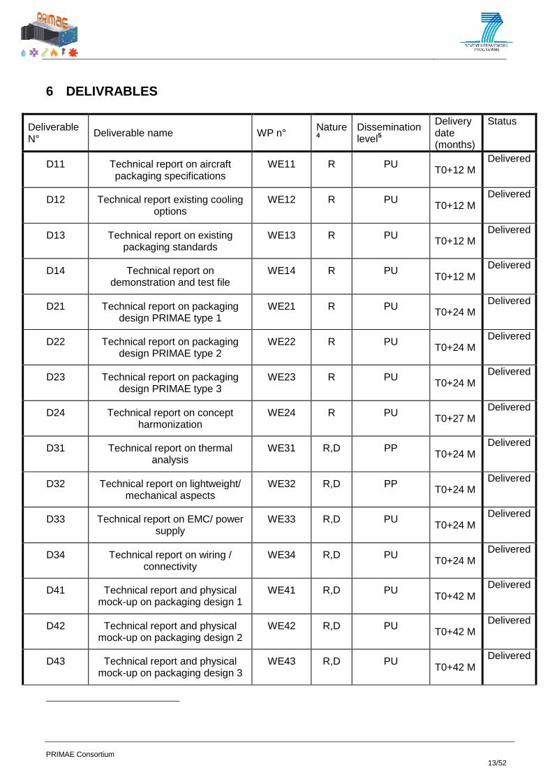
6 DELIVRABLES
Deliverable N° Deliverable name WP n° Nature
4 Dissemination level5
Delivery date (months)
Status
D11 Technical report on aircraft packaging specifications
WE11 R PU T0+12 M Delivered
D12 Technical report existing cooling options
WE12 R PU T0+12 M
Delivered
D13 Technical report on existing packaging standards
WE13 R PU T0+12 M Delivered
D14 Technical report on demonstration and test file
WE14 R PU T0+12 M
Delivered
D21 Technical report on packaging design PRIMAE type 1
WE21 R PU T0+24 M Delivered
D22 Technical report on packaging design PRIMAE type 2
WE22 R PU T0+24 M Delivered
D23 Technical report on packaging design PRIMAE type 3
WE23 R PU T0+24 M
Delivered
D24 Technical report on concept harmonization
WE24 R PU T0+27 M Delivered
D31 Technical report on thermal analysis
WE31 R,D PP T0+24 M
Delivered
D32 Technical report on lightweight/ mechanical aspects
WE32 R,D PP T0+24 M Delivered
D33 Technical report on EMC/ power supply
WE33 R,D PU T0+24 M
Delivered
D34 Technical report on wiring / connectivity
WE34 R,D PU T0+24 M Delivered
D41 Technical report and physical mock-up on packaging design 1
WE41 R,D PU T0+42 M
Delivered
D42 Technical report and physical mock-up on packaging design 2
WE42 R,D PU T0+42 M Delivered
D43 Technical report and physical mock-up on packaging design 3
WE43 R,D PU T0+42 M
Delivered

PRIMAE Consortium 14/52
D44 Technical report on design of test modules and test modules
WE44 R,D PU T0+42 M Delivered
D51 Technical report on electrical/ EMC performance evaluation
WE51 R,D PU T0+48 M
Delivered
D52 Technical report on thermo mechanical performance
evaluation
WE52 R,D PU T0+48 M
Delivered
D61 Technical report on synthesis, WE61 R PU T0+48 M Delivered
D62 Final reports, six monthly and annual management reports
dissemination, pre standardization
WE62 R PU
T0+48 M
Delivered
PRIMAE Consortium 15/52
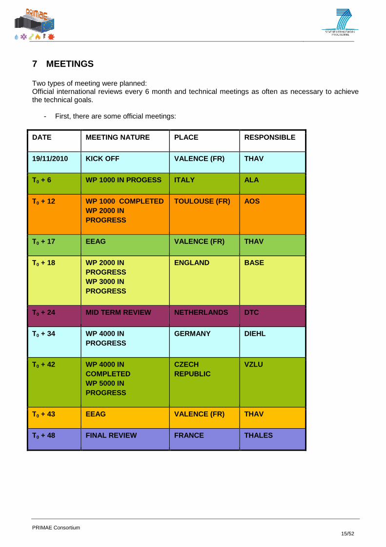
7 MEETINGS
Two types of meeting were planned: Official international reviews every 6 month and technical meetings as often as necessary to achieve the technical goals.
- First, there are some official meetings:
DATE MEETING NATURE PLACE RESPONSIBLE
19/11/2010 KICK OFF VALENCE (FR) THAV
T0 + 6 WP 1000 IN PROGESS ITALY ALA
T0 + 12 WP 1000 COMPLETED WP 2000 IN PROGRESS
TOULOUSE (FR) AOS
T0 + 17 EEAG VALENCE (FR) THAV
T0 + 18 WP 2000 IN PROGRESS WP 3000 IN PROGRESS
ENGLAND BASE
T0 + 24 MID TERM REVIEW NETHERLANDS DTC
T0 + 34 WP 4000 IN PROGRESS
GERMANY DIEHL
T0 + 42 WP 4000 IN COMPLETED WP 5000 IN PROGRESS
CZECH REPUBLIC
VZLU
T0 + 43 EEAG VALENCE (FR) THAV
T0 + 48 FINAL REVIEW FRANCE THALES

PRIMAE Consortium 16/52
WE
11
00
Airc
raft
pa
cka
gin
g
sp
ecific
atio
n
We
be
x 1
KO
M
WE
11
00
14
th
Ma
rch 2
01
1
We
be
x 2
28
th
Ma
rch 2
01
1W
eb
ex 3
18
th A
pril
20
11
We
be
x 4
20
th
June
20
11
We
be
x 5
5th
A
ug
ust 2
01
1
We
be
x 6
7th
O
cto
be
r 2
01
1
We
be
x 7
1
4th
D
ece
mb
er
20
11
Me
etin
g 1
2
9th
Ma
rch
20
12
WE
12
00
Tra
de
-off
exis
ting
co
olin
g
so
lutio
ns
Aud
io 1
KO
M
WE
12
00
22
nd
D
ece
mb
er 2
01
0
Aud
io 2
31
st
Ja
nua
ry 2
01
1A
ud
io 4
22
nd
ap
ril 2
01
1A
ud
io 4
12
th
Ma
y 2
01
1
Aud
io 5
9th
S
ep
tem
be
r 2
01
1
Aud
io6
27
th
Octo
be
r 2
01
1
WE
13
00
Sta
te o
f the
Art
of P
acka
gin
g
sta
nd
ard
s
Aud
io 1
KO
M
WE
13
00
4th
F
eb
rua
ry 2
01
1
Aud
io 2
23
rt M
arc
h 2
01
1A
ud
io 3
31
st M
ay
20
11
Aud
io 4
17
th
June
20
11
WE
14
00
Mo
cks-u
ps a
nd
te
st file
d
efin
ition
Aud
io 1
KO
M
WE
14
00
2nd
M
arc
h 2
01
1
Aud
io 2
28
th
Se
pte
mb
er
20
11
WE
21
00
Pa
cka
gin
g
De
sig
n T
yp
e 1
We
be
x 1
KO
M
WE
21
00
2nd
N
ove
mb
er 2
01
1
Aud
io 1
1th
Ja
nua
ry 2
01
2
Me
etin
g 1
LA
T/
TH
AV
- Va
lence
21
st
Fe
bru
ary
20
12
Me
etin
g 2
T
HA
V/ L
AT
- V
ale
nce
9th
M
arc
h 2
01
3
Aud
io 2
T
HA
V / L
AT
1
1th
June
2
01
2
WE
22
00
Pa
cka
gin
g
De
sig
n T
yp
e 2
We
be
x 1
KO
M
WE
22
00
7th
N
ove
mb
er 2
01
1
Aud
io T
HA
V /
BA
E 6
th J
une
2
01
2
Aud
io 2
BA
E/ T
HA
V
13
th J
une
20
12
WE
23
00
Pa
cka
gin
g
De
sig
n T
yp
e 3
We
be
x 1
KO
M
WE
23
00
9th
F
eb
rua
ry 2
01
2
Aud
io T
HA
V /
DA
s 1
2th
June
20
12
Aud
io
TH
AV
/RA
D
13
th M
arc
h
20
13
Aud
io
TH
AV
/RA
D/T
E/
DA
V/A
OS
Da
s
21
st M
arc
h
20
13
Me
etin
g
TH
AV
/RA
D/D
AV
/D
as/T
E/A
OS
/BA
E
14
th M
ay 2
01
3
Me
etin
g
TH
AV
/RA
D/D
AV
/Da
s/T
E/A
OS
/BA
E 2
5th
June
2
01
3
Aud
io
TH
AV
/BA
E/D
AS
24
th J
uly
2
01
3
Me
etin
g
TH
AV
/KT
R -
Va
lence
17
th
Ja
nua
ry 2
01
3
Aud
io
TH
AV
/KT
R
12
th M
arc
h
20
13
Me
etin
g
TH
AV
/KT
R -
To
ulo
n 2
1st M
ay
20
13
Aud
io
TH
AV
/KT
R/B
AE
/Da
s 3
1st J
uly
2
01
3
Aud
io
TH
AV
/KT
R/B
AE
/Da
s/A
OS
/A
LA
/DA
V/T
E/
RA
D/L
AT
2
9th
Aug
ust
20
13
W3
10
0T
he
rma
l A
na
lysis
Aud
io 1
KO
M
WE
31
00
11
th
Ja
nua
ry 2
01
2
Aud
io 2
31
st
Ma
y 2
01
2
WE
32
00
Lig
htw
eig
ht /
Me
cha
nic
al
Aud
io 1
KO
M
WE
32
00
11
th
Ja
nua
ry 2
01
2
WE
33
00
EM
C S
hie
ldin
g /
Po
we
r Sup
ply
Aud
io 1
KO
M
WE
33
00
11
th
Ja
nua
ry 2
01
2
WE
34
00
Co
nne
ctiv
ity
Aud
io 1
KO
M
WE
33
00
11
th
Ja
nua
ry 2
01
2
Me
etin
g 1
R
AD
- C
hâ
tea
u-
Re
na
ult 3
1st
Ja
nua
ry 2
01
2
WE
41
00
Ma
nufa
ctru
ring
d
esig
n T
yp
e 1
Aud
io
TH
AV
/LA
T 2
6th
N
ove
mb
er 2
01
3
Aud
io
TH
AV
/LA
T
10
th
De
ce
mb
er
20
13
Aud
io T
HA
V/L
AT
1
7th
De
ce
mb
er 2
01
3
Aud
io
TH
AV
/LA
T
07
th F
eb
rua
ry
20
14
Aud
io
TH
AV
/LA
T
10
th M
arc
h
20
14
Aud
io
TH
AV
/LA
T
08
th A
pril
20
14
WE
42
00
Ma
nufa
ctru
ring
d
esig
n T
yp
e 2
WE
43
00
Ma
nufa
ctu
ring
d
esig
n T
yp
e 3
WE
44
00
Ele
ctro
nic
s
rep
rese
nta
tive
fu
nctio
ns
Aud
io 1
T
HA
V/K
TR
10
th
Octo
be
r 20
13
Aud
io 2
T
HA
V/K
TR
1
9th
D
ece
mb
er
20
13
Aud
io 3
TH
AV
/KT
R
06
th F
eb
rua
ry 2
01
4
Aud
io 4
T
HA
V/K
TR
0
7th
Ma
rch
20
14
WE
50
00
Pe
rform
ance
e
va
lua
tion
Audio
1
TH
AV
/KT
R/C
EL
2nd F
ebru
ary
2014
Audio
2
TH
AV
/KT
R 7
th
Marc
h 2
014
Audio
3
TH
AV
/KT
R/R
A16th
July
2014
WE
60
00
Pa
cka
gin
g
se
lectio
n /
Ma
na
ge
me
nt
Aud
io
TH
AV
/KT
R/B
AE
/Da
s/A
OS
/RA
D/
LA
T/C
EL
/VZ
LU
1
2th
Ma
rch
20
14
Aud
io
TH
AV
/KT
R/B
AE
/Da
s/A
OS
/A
LA
/DA
V/T
E/R
AD
/LA
T
13
th
Se
pte
mb
er 2
01
3
Aud
io 4
with
T
E 1
2th
M
arc
h 2
01
2
Aud
io 5
with
T
E 1
1th
Ap
ril 2
01
2
Aud
io 6
with
T
E 1
0th
Ma
y
20
12
WE
24
00
Co
nce
pt
Ha
rmo
niz
atio
n
Aud
io 1
with
R
AD
30
rd
Ja
nua
ry 2
01
2
Me
etin
g 1
with
T
E 2
8
Fe
bru
ary
2
01
2
Aud
io w
ith T
E 2
8th
F
eb
rua
ry 2
01
2
Aud
io 3
with
R
AD
06
th
Ma
rch 2
01
2
Review meeting

PRIMAE Consortium 17/52
8 DISSEMINATION PRIMAE WEBSITE: www.primae.org The website attracted interest and was visited more than 1000 times per month of it highest rate. PRIMAE presentations thought conferences and work-shops: PRIMAE EEAG meeting , Valence, (March 29-30, 2012) IHPC, Lyon, (May, 2012) International Heat Pipe Conference IHPC, Kanpur, (October, 2013) International Heat Pipe Conference AEEC (SAI) Subcommittee meeting, Frankfurt, (June 27-28, 2012) Systems Architecture and Interfaces IMAPS, 8th European Advanced Technology Workshop on micro packaging and Thermal management (La Rochelle - 6, 7 February 2013)

PRIMAE Consortium 18/52
“Entretiens de Toulouse ” (23, 24 april 2013) Equipment packaging: the need for radical changes (Thales) IMAPS, 9th European Advanced Technology Workshop on micro packaging and Thermal management (La Rochelle - 6, 7 February 2014) Publication R. Hodot, , C. Sarno, B. TRUFFART, Vincent POMME, J. Coulloux, C. Zilio, S. MANCIN, Electronic cooling for avionics using loop heat pipes and mini-Vapour Cycle Systems, IMAPS, La Rochelle, France, February 4-5, 2015 R. Hodot, V. Sartre, J. Coulloux, C. Sarno Electornic cooling for avionics using loop heat pipe with cylindrical evaporator, IMAPS, La Rochelle, France, February 6-7, 2014 S. Safouene, T. Barreteau, V. Sartre, R. Hodot, Experimental comparison of loop heat pipes performance with various evaporator designs, 17th International Heat Pipe Conference, Kanpur, India, October 13-17, 2013, 6 p. R. Hodot, V. Sartre, F. Lefevre, C. Sarno, 3D modeling and optimization of a loop heat pipe evaporator,17th International Heat Pipe Conference, Kanpur, India, October 13-17, 2013, 6 p. R. Hodot, Loop heat pipes for the thermal management of hot spots in future electronic equipments, IMAPS, La Rochelle, France, February 6-7, 2013 C. Sarno, C. Tantolin, R. Hodot, Y. Maydanik, S. Vershinin, Loop Thermosyphons for the thermal management of an aircraft electronic box, 16th International Heat Pipe Conference, Lyon, France, May 20-24, 2012, 6 p.
9 EEAG The External Experts Advisory Group (EEAG) objective is to provide input constraints and requirements and also to facilitate the acceptance of this new proposed standard in the avionics and equipment world to enlarge the base of the future Standard to a wider community of users outside Europe and worldwide The EEAG is composed of end–users (Airlines, aircraft manufacturers, equipment’s manufacturers, component providers…) and will interact with the project. Two EEAG Work shop have been organised during the life of the project.
• The first EEAG work shop was held in Valence at T0+17:
A Workshop concerning the PRIMAE project has taken place in Valence, on the 29th - 30th March 2012.
Design & Development
Requirements, system specification
Testbed integration Validation
Packaging specification
Exploitation Dissimination
End User (EEAG)
Exchange on the selected technologies
RTD Project
Evaluation Recommandations
Results Pre-Standard

PRIMAE Consortium 19/52
The workshop has been successful with about 100 participants coming from 44 companies through 10 countries.
PRIMAE project has been launched in the Frame of the FP7 call N°3 concerning the Aeronautics and Transport by the main players of the domain (Airframers and Equipment Manufacturers). The goal of this project is to establish a new standard able to replace the 30 years old existing standard by a more modern and competitive one.
In order to define a successful concept applicable worldwide, a multidisciplinary approach has been proposed including:
- The rack architectures (module type and organization)
- The cooling management solution & architectures
- The structural and vibration aspects
- The electromagnetic shielding
- The connectors aspect (optical, Gb/s)
- The signals and power supply distribution
- The upgrade and maintenance aspects.
The goal of this workshop was to enlarge the base of the future Standard to a wider community of users outside Europe, including airlines and aircraft manufacturers.

PRIMAE Consortium 20/52
During the work shop, Thales recalled the most important challenges, followed by an Airbus presentation of the needs and the Dassault presentation of the State of the Art, following by presentations from the partners, BAEs, DHIEL, Alenia, Radiall and Tyco with an active participation from the audience.
Exhibition booths were prepared to show latest Thales technologies including laser gyros, MEMS, power supply, Cabinet Packaging…

PRIMAE Consortium 21/52
The workshop also continued in a festive and friendly atmosphere.

PRIMAE Consortium 22/52
• The second EEAG work shop took place in Valence at T0+43:
The goal of this workshop was to enlarge the base of the future Standard to a wider community of users outside Europe, including airlines and aircraft manufacturers. It was also intended to present the results achieved and to discuss the next possible steps. The workshop has been successful with about 60 participants coming from 25 companies through 10 countries.
The PRIMAE consortium partners presented the requirements, the state of the art and the packaging issues in each domain.
Claude Sarno, project leader TAV Anaïs Hourcade, Airbus Pierpaolo Borelli, Alenia

PRIMAE Consortium 23/52
Interesting points of view where exchanged with the audience (Boeing, Airbus, Embraer, Etihad, Rockwell, Airbus Helicopter, BAE…).
Matthew McAlonis, TE
The final important topic rised by the EEAG was “wh at’s next?” and the participant agreed on:
Terminate the PRIMAE evaluations positively (end 2014).
Launch the ASD-STAN standardization through the STAN D2 S11 group if a target programme is
defined.
Continue the development of the PRIMAE standard either through an aircraft programme or through
further R&T studies.
It is interesting to notice that the aerospace community is widely open to the establishment of an international standard particularly the US companies through a transatlantic cooperation as initiated thought this PRIMAEUS project.

PRIMAE Consortium 24/52
PERIOD 1 (12 months) PERIOD 2 (15 months) PERIOD 3 (21 months)
2010
T0 : Nov. 1 2 3 5 6 7 8 10 11 12 13 14 15
Periodic Reports
Task final report
Periodic Cost Statement
Periodic Progress Report
Mid term assesment report
Final Reports
Final technical reports
Final Cost Statement
Exploitation Report
Publishable Final summary
Publishable synthesis
16
20142012
4
2013
9
2011
10 REPORTING PERIODS
Three main reporting periods have been defined along the course of the project (T0+12, T0+27, T0+48).
11 LEGAL ASPECTS Two amendments have been discussed and Amendment n°1 -:
Amendment N°1 to Grant Agreement N°2013265423 date d 7th January 2011 Addition of a new entity
o BAE Systems (Operations) Ltd, established in Warrick House, FARNBOROUGH, GU14 6YU.
Modifications of Annex I – Description of Work Revision of Part A and B of Annex I dates 4th May 2011 Modification of the legal entity Tyco Electronics UK ltd’s details.
Amendment n°2:
PRIMAE project is governed under : o Amendment N°2 to Grant Agreement N° 265413 dated 2 8th August 2013. o Consortium Agreement signed by Thales Avionics on 22nd July 2011.
Main changes on the Amendment n°2 of the Grant Ag reement o Update of some beneficiaries organization status and authorized representatives, o Modification of the project duration, o Update of PRIMAE DOW with new schedule and milestones.

PRIMAE Consortium 25/52
12 PRE-STANDARDIZATON
12.1 OBJECTIVES
One of the goal of the PRIMAE project is the production of a draft standard intended to prepare the standardization for the future avionics packaging. The synthesis document defines interfaces at module level (LRM) and rack level (LRU) and propose possible compliances with current industrial standards Many possible steps have been foreseen to go to an international standard:
- The first basic one is to implement the concept resulting from the study on a new aircraft development inside manufacturers programs (Airbus, Alenia, Dassault...).
- Then, to really standardize the “PRIMAE” packaging concept, two possibilities are offered in ascending complexity order:
- At the European level first , creating an “EN” standard through the European ASD-STAN organisation. To do so, the subject must be taken into account by an ad hoc working group. The current electrical working group (C2) of the ASD-STAN organization doesn’t have such an existing sub-group for packaging aspect. The subject has been raised to the ASD-STAN board by the consortium members. The proposed option is to create a new “C2” sub-group for MOAA Modular and Open Avionics Architecture. This new working group would be linked with the current electrical connector working group C2WG3 and the current optical working group C2WG10. During the course of the PRIMAE project, the consortium has maintained contacts with the ASD-STAN through the members of the consortium pertaining to this committee, and has informed them on the advancement of the packaging concept, as soon as the first results were made available.
- Then the next possible step would be to standardize it through an ARINC specification . The ARINC (Aeronautical Radio, Incorporated) organization includes, the main international Airlines among which three were invited to the PRIMAE EEAG (Air France, Lufthansa, and Delta). A dedicated committee named AEEC deals with “Engineering Standards for Avionics and Cabin Systems”. In this AEEC committee, the subcommittee NIC specializes in “New Installation Concepts”. The existing ARINC 600 standard was worked out through the NIC subcommittee.
For new standardization projects, an APIM (ARINC Project Initiation/Modification) document should be submitted. It is to mention that the support of an Airline company for the project is highly recommended. Another important point is that the yearly work program of each ARINC committee is established during its annual meeting, consequently, the APIM document for standardization should be created and submitted early enough to the committee, and the year preceding the start of the work. During the course of the PRIMAE project, the consortium has been in touch with the ASD-STAN through the members of the consortium pertaining to this committee, and informed them on the progress of the packaging concept, as soon as the first results were available, we have considered the appropriateness of transferring these results to the ad-hoc packaging group depending on their consistency at that time. The draft specification document produced by this WE combined with the ASD-STAN progress results will constitute the base of a future APIM document for the ARINC, if this route is confirmed through the next PRIMAEUS program to be launched with the US on a multilateral base.
12.1.1 Arinc Activities A contact has been established with the ARINC organisation, and a formal presentation of PRIMAE has been organised in Franckfurt in June 2012 to the AEEC Systems Architecture and Interfaces (SAI) Subcommittee The major comment from the audience composed of the main airlines and airframers, was that to have a chance to become an international standard, PRIMAE should enlarge the base of participants and mainly the US base as the ARINC is composed in majority of US companies

PRIMAE Consortium 26/52
After the meeting it was proposed to the PRIMAE consortium to prepare a next project called PRIMAEUS in order to involve our US counterpart including Boeing, Rockwell Collins, Honeywell. These companies have been invited to participate to the PRIMAE EEAG workshop dedicated to external dessimination The discussions have been very positive, and the PRIMAEUS project (extended also to other non-European countries like CHINA , Russia, Brazil, Canada) should be possibly launched when the appropriate window will appear in the H2020 project as well as the US FAA funding. The difficulty here will be to synchronise both funding, and also with the other countries.
12.1.2 ASD-STAN Activities An expert group among the partners has been named to prepare the harmonized draft standard The draft has been produced and is described here after
12.2 INTRODUCTION
12.2.1 Purpose The purpose of the PRIMAE Program is to define and validate a set of open Packaging Modular Architecture standards (PMA), concepts and guidelines for Packaging Modular architecture (PMA) in order to meet the main PRIMAE drivers. The standards, concepts and guidelines produced by the Program are to be applicable to both new Aircraft and update programs. The main drivers for the PRIMAE Program are: ⎯ Reduced life cycle costs, ⎯ Improved mission performance, ⎯ Improved operational performance. The Standards are organized as a set of documents including: ⎯ A set of agreed standards that describe, using a top down approach, the Packaging Architecture overview to all Interfaces required implementing the core within avionics systems, ⎯ The guidelines for system implementation through application of the standards. (TBD). The document hierarchy is given hereafter

PRIMAE Consortium 27/52
(1*) Standards document for “determinate blade & rack” are not includes in this proposal standard phase
Picture 1 : Standard Documentation Organization cha rt
12.2.2 Document Structure The document contains the following sections:
Section 1, gives the scope of the document, Section 2, identifies normative references, Section 3, gives the terms, definitions and abbreviations, Section 4, presents the set of architecture drivers and characteristics as well as an introduction to PMA, Section 5, defines the architecture standard, and introduces the other standards,
Annex A, presents the different packaging architecture.
12.3 SCOPE The purpose of this standard is to establish uniform requirements for the Packaging Modular Avionic (PMA) systems as defined by the PRIMAE Program. The PMA architecture can be built by using common components. These components are specified in separate standards as modular connectors. Ways of using these components are described in a set of guidelines.
12.4 NORMATIVE REFERENCES
12.4.1 AECMA References This European Standard incorporates by dated or undated reference provisions from other publications. These normative references are cited at the appropriate places in the text and the publications are listed hereafter. For dated references, subsequent amendments to or revisions of any
Standards for Packaging Module and interfaces TR/EN
xxxx-001 and -002 (performances & arrangement
Standards For Packaging Architecture TR/EN xxxx Proposed
Standards for determinate blade TR/EN xxx-002 (1*)
Guidelines for Packaging issues
- …TBD… Standards for communication module and others (external to packaging standard)
Standards for modular
connectors ENyyyy
Standards for determinate Rack TR/EN xxx-003 (1*)

PRIMAE Consortium 28/52
of these publications apply to this European Standard only when incorporated in it by amendment or revision. For undated references the latest edition of the publication referred to applies.
TR/EN xxxx-002 Aerospace series - Modular and open avionics Architecture - Part 002: functional blades for Packaging avionic architecture. (Performances and arrangements, ) not included in this proposal specification phase)
TR/EN xxxx-003 Aerospace series - Modular and open avionics Architecture - Part 003: functional module for Packaging avionic architecture. (Not included in this proposal specification phase) TR/EN xxxx-004 Aerospace series - Modular and open avionics Architecture - Part 004: functional Rack for Packaging avionic architecture. (Not includes in this proposal specification phase) EN2591-205 Aerospace series. Elements of electrical and optical connection. Test methods. Housing (shell) electrical continuity EN 2591-315 Aerospace series. Cable, electrical, aircraft use. Test methods. Part 315. Resistance to fluids EN3197 Aerospace series - Installation of aircraft electrical and optical interconnection systems EN.... Aerospace series – electrical contacts crimped EN.... Aerospace series – Opticall contacts EN 4529-002 Aerospace series – Aerospace series - Elements of electrical and optical connection - Sealing plugs - Part 002: Index of product standards EN tbd-002 Aerospace series - Connectors, optical, rectangular, modular, multicontact, 1,25 diameter ferrule, with removable alignment sleeve holder - Part 002: List of product standards Pr ENyyyy-001 Aerospace series – Connectors, electrical and optical, rectangular modular – Operating temperature TBD 175°C (or 125°C) – Part 0 01: Technical specification.
Pr ENyyyy-002 Aerospace series – Connectors, electrical and optical, rectangular modular – Operating temperature TBD 175°C (or 125°C ) – Part 002: specifications of performances and contacts arrangements Pr ENyyyy-003 Aerospace series – Connectors, electrical and optical, rectangular modular – Operating temperature TBD 175°C (or 125°C ) continuous – Part 003: rectangular inserts and insert extraction tool – Product standard. Pr ENyyyy-011 Aerospace series – Connectors, electrical and optical, rectangular modular – Operating temperature TBD 175°C (or 125°C ) continuous – Part 011: Male housing size .., class A, C and E – Product standard. Pr ENyyyy-012 Aerospace series – Connectors, electrical and optical, rectangular modular – Operating temperature TBD 175°C (or 125°C ) continuous – Part 012: Female housing size ..., class A, C and E – Product standard.
12.4.2 Others refererence
ARINC Specification 600 Air Transport Avionics Equipment Interfaces

PRIMAE Consortium 29/52
EUROCAE ED14 / RTCA DO160F Environmental Conditions and test Procedures for Airborne Equipment ISO 2669 Environmental tests for aircraft equipment -- Steady-state acceleration
12.5 TERMS, DEFINITIONS AND ABBREVIATIONS
12.5.1 Terms and definitions Use of “shall”, “should” and “may” within the standards observe the following rules: ⎯ The word SHALL in the text expresses a mandatory requirement of the standard. ⎯ The word SHOULD in the text expresses a recommendation or advice on implementing such a requirement of the standard. It is expected that such recommendations or advice will be followed unless good reasons are stated for not doing so. ⎯ The word MAY in the text expresses a permissible practice or action. It does not express a requirement of the standard.
12.5.2 Abbreviations and terms
Admission plenum
Backplane A part of cabinet which allows all internal electrical links and support harness for direct aircraft connection part.
Blade Individual module which includes electronics function, inserted and extractible directly from the rack (is also named LRM).
Cabinet A complete definition of total assembly of Rack, modules, backplane, and optional devices for airflow interfaces.
Chassis Assembly of Rack, Bakplane, ICB, and may include door, admission plenum and extraction plenum).
CPC Core Processing Cabinet
EN European Norm
Extraction plenum
ICB Interconnection Customization Box
IED Insertion Extraction Device
PCB Printed Circuit Board
PMA Packaging Modular Architecture
PSM Power Supply Module
Rack Main mechanical structure witch can receive all sub-assembly parts and blades.
RHPC Remote High Power Cabinet

PRIMAE Consortium 30/52
RIOIC Remote I/O Intensive Cabinet
TBC To Be Confirmed
TBD To Be Defined
XMC Standard of electronic board in mezzanine
Picture 2 : Abbreviations and Terms table

PRIMAE Consortium 31/52
12.5.3 Definition of axes in 3D for Blades and Cabi net
Picture 3 : 3D axis reference
PRIMAE Consortium 32/52
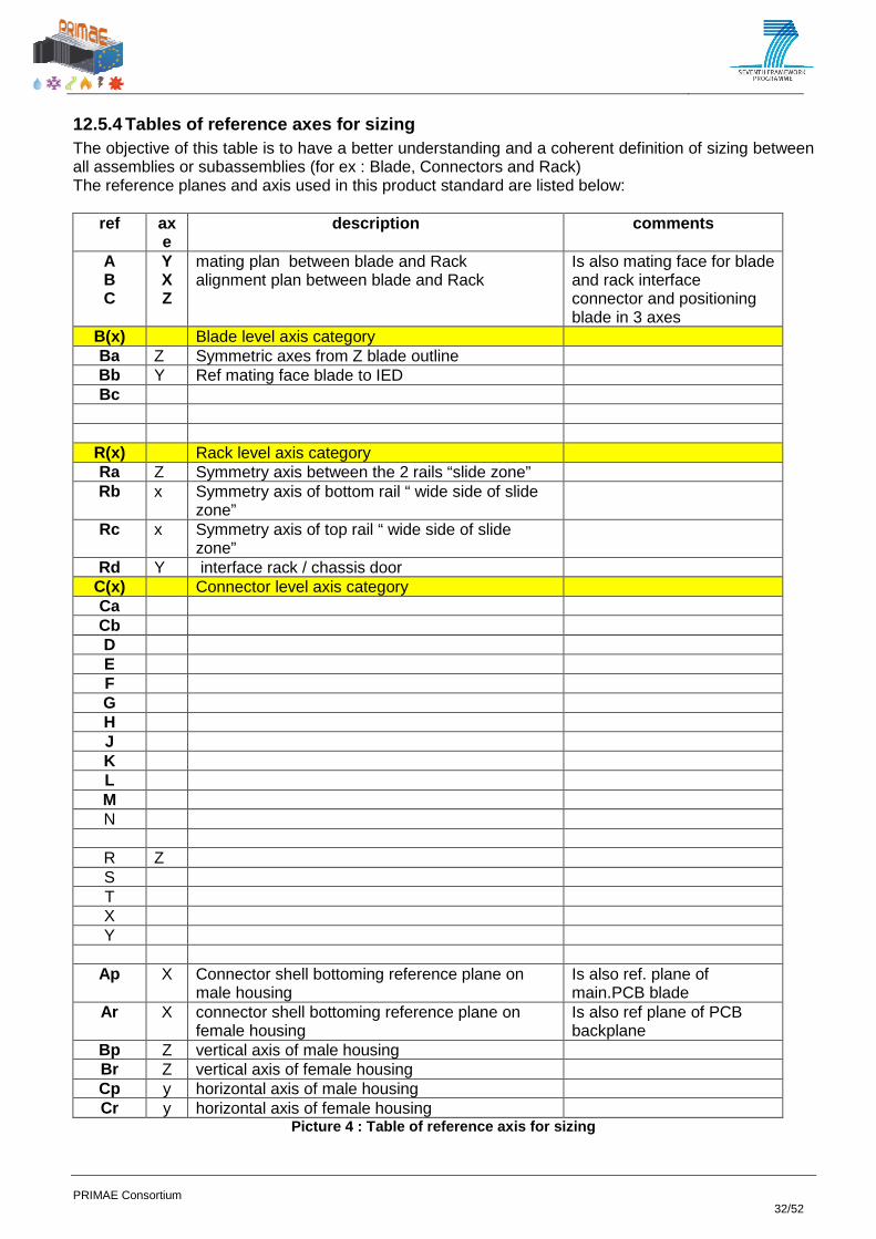
12.5.4 Tables of reference axes for sizing The objective of this table is to have a better understanding and a coherent definition of sizing between all assemblies or subassemblies (for ex : Blade, Connectors and Rack) The reference planes and axis used in this product standard are listed below:
ref axe
description comments
A B C
Y X Z
mating plan between blade and Rack alignment plan between blade and Rack
Is also mating face for blade and rack interface connector and positioning blade in 3 axes
B(x) Blade level axis category Ba Z Symmetric axes from Z blade outline Bb Y Ref mating face blade to IED Bc
R(x) Rack level axis category Ra Z Symmetry axis between the 2 rails “slide zone” Rb x Symmetry axis of bottom rail “ wide side of slide
zone”
Rc x Symmetry axis of top rail “ wide side of slide zone”
Rd Y interface rack / chassis door C(x) Connector level axis category Ca Cb D E F G H J K L M N
R Z S T X Y
Ap X Connector shell bottoming reference plane on male housing
Is also ref. plane of main.PCB blade
Ar X connector shell bottoming reference plane on female housing
Is also ref plane of PCB backplane
Bp Z vertical axis of male housing Br Z vertical axis of female housing Cp y horizontal axis of male housing Cr y horizontal axis of female housing
Picture 4 : Table of reference axis for sizing

PRIMAE Consortium 33/52
12.6 DESCRIPTION OF MODELS Modular electrical/optical rectangular, Empty Cabinet and blade, environmental resistant, shall be defined by the final customer at the cabinet level. – Standard cabinet environment is defined in chap. 8 Blades shall be internal Cabinet connected and may be partially direct connected to aircraft with using electrical and/or optical standardized contacts.
Picture 6 : Cabinet and Blades
Optional parts are defined according to aircraft interface and aircraft airflow distribution capability (inlet and outlet airflow adaptor box in interface with airflow aircraft distribution-. (not defined in this standard).
Cabinet
Picture 5 : Cabinet organization

PRIMAE Consortium 34/52
- For each case the cabinet is common: independent of the configuration and the location in the aircraft. The width can be decreased in the case of compact rack, but the manufacturing is the same. - The backplane is specific for each configuration: the arrangement of the connectors and the type of contact are different. - Depending on the position and the aircraft manufacturer, the plenums and the back-up cooling are specific. The back-up is removable in aircraft.
Picture 7 : Example of Chassis sub-assembly organiz ation (case of blades in vertical position)
Outlet plenum
Chassis
Backup cooling
Removable fans unit
Door
PRIMAE Consortium 35/52
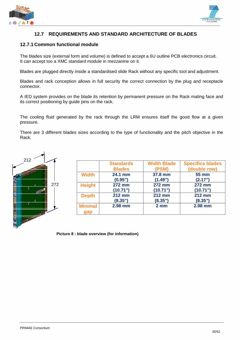
12.7 REQUIREMENTS AND STANDARD ARCHITECTURE OF BLA DES
12.7.1 Common functional module The blades size (external form and volume) is defined to accept a 6U outline PCB electronics circuit. It can accept too a XMC standard module in mezzanine on it. Blades are plugged directly inside a standardised slide Rack without any specific tool and adjustment. Blades and rack conception allows in full security the correct connection by the plug and receptacle connector. A IED system provides on the blade its retention by permanent pressure on the Rack mating face and its correct positioning by guide pins on the rack. The cooling fluid generated by the rack through the LRM ensures itself the good flow at a given pressure. There are 3 different blades sizes according to the type of functionality and the pitch objective in the Rack.
Standards Blades
Width Blade (PSM)
Specifics blades (double row)
Width 24.1 mm (0.95”)
37.8 mm (1.49”)
55 mm (2.17”)
Height 272 mm (10.71”)
272 mm (10.71”)
272 mm (10.71”)
Depth 212 mm (8.35”)
212 mm (8.35”)
212 mm (8.35”)
Mini mal gap
2.98 mm 2 mm 2.98 mm
2
2
272
212
Picture 8 : blade overview (for information)

PRIMAE Consortium 36/52
12.7.2 Packaging description
12.7.2.1 Blade outline
Picture 9 : Blade TYCO/RADIALL
PRIMAE Consortium 37/52
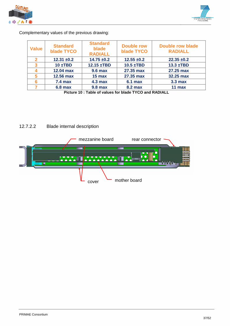
Complementary values of the previous drawing:
Value Standard blade TYCO
Standard blade
RADIALL
Double row blade TYCO
Double row blade RADIALL
2 12.31 ±0.2 14.75 ±0.2 12.55 ±0.2 22.35 ±0.2 3 10 ±TBD 12.15 ±TBD 10.5 ±TBD 13.3 ±TBD 4 12.04 max 9.6 max 27.35 max 27.25 max 5 12.56 max 15 max 27.35 max 32.25 max 6 7.4 max 4.3 max 6.1 max 3.3 max 7 6.8 max 9.8 max 8.2 max 11 max
Picture 10 : Table of values for blade TYCO and RAD IALL
12.7.2.2 Blade internal description
rear connector
cover mother board
mezzanine board

PRIMAE Consortium 38/52
Picture 11 : section TYCO blade
Picture 12 : section RADIALL blade

PRIMAE Consortium 39/52
Chassis interface outline conditions
Picture 13 : TYCO/RADIALL section of the rack

PRIMAE Consortium 40/52
Complementary values of the previous drawing:
Value Standard blade TYCO
Standard blade RADIALL
Double row blade TYCO
Double row blade RADIALL
1 8 ±TBD 5.85 ±TBD 7.5 ±TBD 4.7 ±TBD 2 11.99 ±TBD 9.55 ±TBD 11.99 ±TBD 7.45 ±TBD 3 6.5 max 4.35 max 6 max 3.2 max 4 7.6 max 9.35 max 8.1 max 10.9 max
Picture 14 : Table of values for TYCO/RADIALL secti on of the rack
Picture 15 : rack section Door
Rails
Chassis
Backplane
IED retaining stud

PRIMAE Consortium 41/52
12.8 REQUIREMENTS AND STANDARD ARCHITECTURE OF RAC K (BASIS)
12.8.1 Common functional rack
12.8.2 Rack basis packaging description
Picture 16 : interface blade/rail
PRIMAE Consortium 42/52
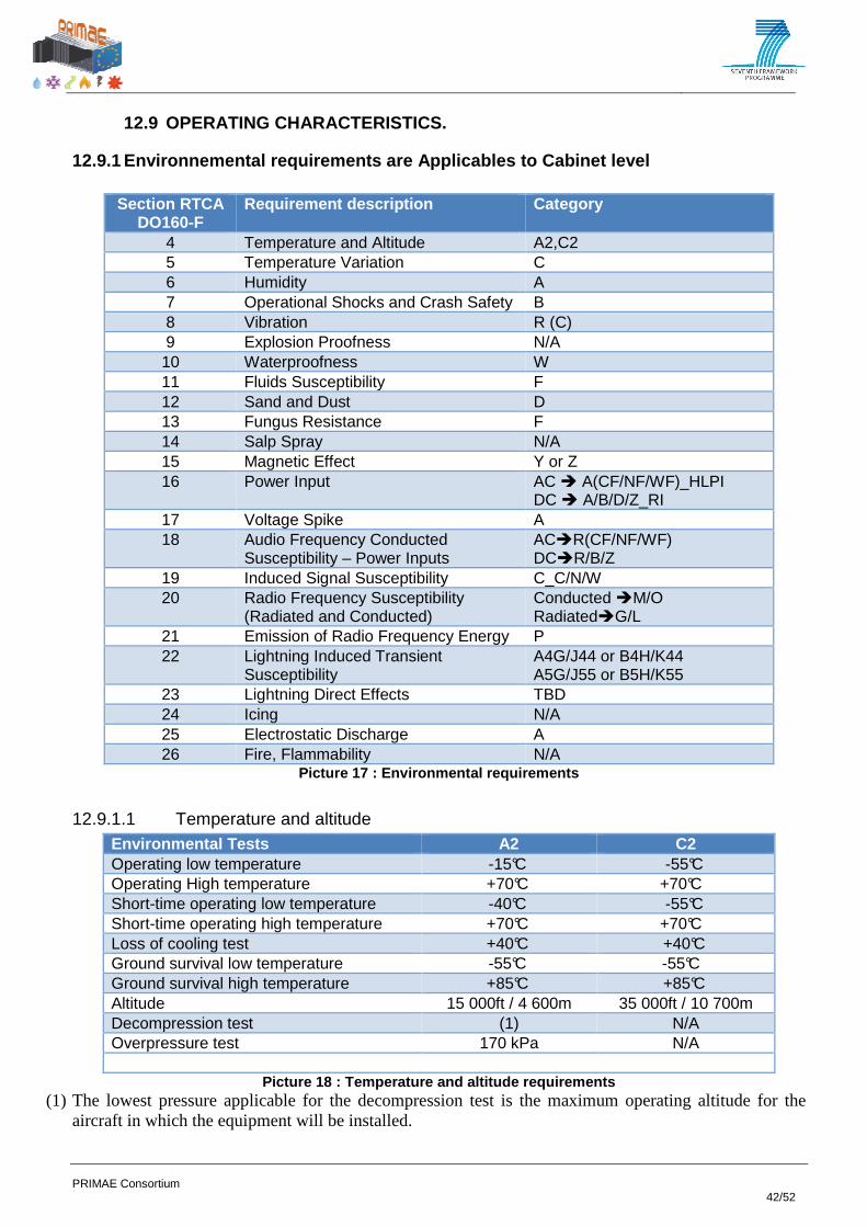
12.9 OPERATING CHARACTERISTICS.
12.9.1 Environnemental requirements are Applicables to Cabinet level
Section RTCA DO160-F
Requirement description Category
4 Temperature and Altitude A2,C2 5 Temperature Variation C 6 Humidity A 7 Operational Shocks and Crash Safety B 8 Vibration R (C) 9 Explosion Proofness N/A 10 Waterproofness W 11 Fluids Susceptibility F 12 Sand and Dust D 13 Fungus Resistance F 14 Salp Spray N/A 15 Magnetic Effect Y or Z 16 Power Input AC A(CF/NF/WF)_HLPI
DC A/B/D/Z_RI 17 Voltage Spike A 18 Audio Frequency Conducted
Susceptibility – Power Inputs ACR(CF/NF/WF) DCR/B/Z
19 Induced Signal Susceptibility C_C/N/W 20 Radio Frequency Susceptibility
(Radiated and Conducted) Conducted M/O RadiatedG/L
21 Emission of Radio Frequency Energy P 22 Lightning Induced Transient
Susceptibility A4G/J44 or B4H/K44 A5G/J55 or B5H/K55
23 Lightning Direct Effects TBD 24 Icing N/A 25 Electrostatic Discharge A 26 Fire, Flammability N/A
Picture 17 : Environmental requirements
12.9.1.1 Temperature and altitude Environmental Tests A2 C2 Operating low temperature -15°C -55°C Operating High temperature +70°C +70°C Short-time operating low temperature -40°C -55°C Short-time operating high temperature +70°C +70°C Loss of cooling test +40°C +40°C Ground survival low temperature -55°C -55°C Ground survival high temperature +85°C +85°C Altitude 15 000ft / 4 600m 35 000ft / 10 700m Decompression test (1) N/A Overpressure test 170 kPa N/A
Picture 18 : Temperature and altitude requirements (1) The lowest pressure applicable for the decompression test is the maximum operating altitude for the
aircraft in which the equipment will be installed.

PRIMAE Consortium 43/52
12.9.1.2 Temperature Variation
Category C - For equipment in a temperature-controlled internal section of the aircraft: 2°C minimum per minute.
12.9.1.3 Humidity Category A - Standard Humidity Environment
The standard humidity environment ordinarily provides an adequate test environment for equipment intended for installation in civil aircraft, non-civil transport aircraft and other classes, within environmentally controlled compartments of aircraft in which the severe humidity environment is not normally encountered.
12.9.1.4 Operational Shocks and Crash Safety Category B - Equipment tested for standard operational shock and crash safety.
12.9.1.5 Vibration Fixed-Wing - Sine of 3 Hrs/Axis less 30 min/dwell (max 4 dwells) or Random at perf. Level (minimum of 10 minutes) and 3 Hrs Endurance level (repeat in all 3 axes).
12.9.1.6 Waterproofness Category W - Equipment that is installed in locations where it is subjected to falling water (generally the result of condensation) in the course of normal aircraft operations is identified as Category W. For equipment intended for installation in such locations, the drip proof test procedure applies and the equipment is identified as Category W.
12.9.1.7 Fluids Susceptibility
Category F - Equipment that has passed the tests covered in this section is identified as Category F. Details of the test fluids involved and the methods used shall be provided in the Environmental Qualification Form.
12.9.1.8 Sand and Dust
Category D - Equipment tested as recommended in the following paragraphs for Dust test is identified as Category D. Such equipment can be installed in locations where the equipment is subjected to blowing dust in the course of normal aircraft operations.
12.9.1.9 Fungus Resistance Category F - Equipment that is installed in an environment where it will be exposed to severe fungus contamination is identified as Category F and shall be subjected to the fungus resistance test. If all materials used in the construction of the equipment can be shown to be non-nutrients for the growth of fungi, either through their composition or through previous testing, this test is not required. If non-nutrient material certification is utilized for this verification, this fact shall be declared on the Environmental Qualification Form.

PRIMAE Consortium 44/52
12.9.2 Contacts conditions - ELECTRICAL CONDITIONS Rated current : according to standards for contacts. - Insulation resistance at ambient temperature: 5000MΩ. - Withstanding voltage at sea level: 1500 V r.m.s. - Withstanding voltage from 15000 m to 21000 m: 800 V r.m.s.
12.9.2.1 Environmental conditions. - Minimum temperature: TBD°C - Maximum temperature: TBD class C at +125°C - Corrosion resistance and fluid resistance: TBD see EN yyyy-001 or ENxxxx-001
12.9.2.2 Mechanical conditions. Mechanical endurance : 500 TBD mating and unmating cycles for contacts; 100 TBD mating and unmating cycles for locking mechanisms.
12.9.2.3 Housing electrical continuity. Maximum resistance between blade and empty cabinet is TBD (mΩ)
12.9.2.4 Shielding effectiveness.
Frequency (MHz) Minimum attenuation (dB) 100 65 200 63 300 63 400 62 500 60 600 60
PRIMAE Consortium 45/52
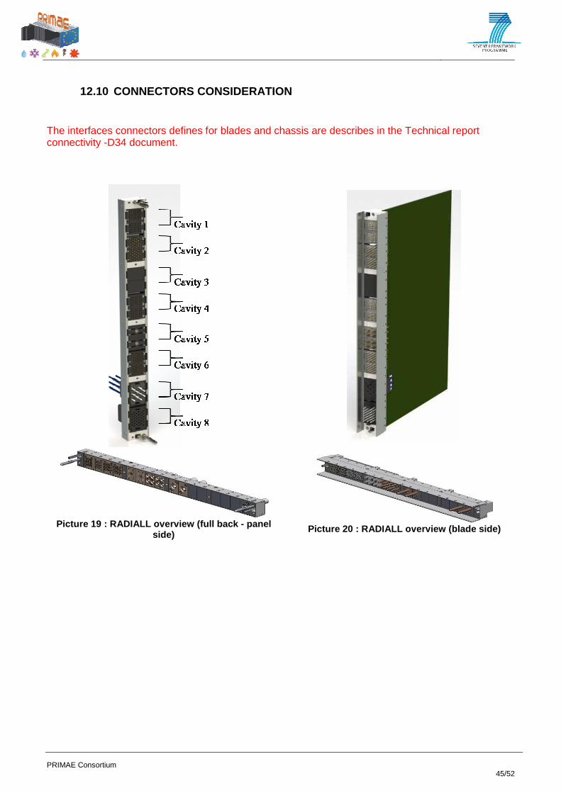
12.10 CONNECTORS CONSIDERATION The interfaces connectors defines for blades and chassis are describes in the Technical report connectivity -D34 document.
Picture 19 : RADIALL overview (full back - panel
side)
Picture 20 : RADIALL overview (blade side)

PRIMAE Consortium 46/52
Picture 21 : TYCO overview (full back - panel side)
Picture 22 : TYCO overview (blade side)
shielding concept Ty-rap harness hold concept Picture 23 : RADIALL - Direct aircraft connection ( cabinet side)

PRIMAE Consortium 47/52
shielding concept Ty-rap harness hold concept Picture 24 : TYCO - Direct aircraft connection (cab inet side)
12.10.1 Connector bezel

PRIMAE Consortium 48/52
12.10.2 Modules contact arrangements. Module and half module consideration Dans chacun des 4 compartiments, on peut installer 2 modules ou 4 demi-modules suivant les besoin d’interface du blade avec le Backplane . Chacun des compartiments peut aussi être composer de 2 demi modules de contacts
12.10.2.1 High speed module => at least X 100-Ohms differential pairs
Blade side (press-fit) Back-panel side ( press-fit)
12.10.2.2 I/O module => at least X contacts / 3 Amp.
Blade side Back-panel side ( press-fit)
12.10.2.3 Power module => at least 10 Amps / 36 Amps / 70 Amps
10 Amp 36 Amps 70 Amps
Blade side Back-panel side Blade side Back-panel
side Blade side (press fit)

PRIMAE Consortium 49/52
12.10.2.4 Bonding module
12.10.2.5 Direct aircraft modules
• Signal contacts => 45x #22 contacts (conform to ARINC 600 specification ) o with male crimping technology on cabinet side o male contact is protected by the insert
o female press-fit and/or soldering technology on blade side
• others signal contacts
o modules definition accept all contacts type meet in ARINC600 specification /EN3155,
• module for COAX. / TRIAX. / QUADRAX / OPTICAL o modules definition accept all contacts type meet in ARINC600 specification / EN 3155,

PRIMAE Consortium 50/52
13 CONCLUSION This project grouping together the major European aerospace players has been a unique opportunity to define common requirements and propose solutions in the complex and multidomain field of equipment packaging for the future aerospace equipment. The results are impressive and several above the state of the art technologies have been successfully implemented (New cooling technologies, direct aircraft connectivity, modular versatile connectors, and composite lightweight structures). In more details: Three racks versions have been developed during the PRIMAE project. These racks families share the same blades and have been designed for different functions and environments.
CPC : Thav FR RHPC : BAE UK RIOIC : Diehl GE
Two Modular connectors have been produced; these connectors propose direct aircraft connectivity and are compatibles for the PRIMAE racks.
TYCO RADIALL
New advanced cooling techniques have been developed and tested positively, these technique are capable of hot spot up to 30 w and 100 w for total power disipation.

PRIMAE Consortium 51/52
A composite version of CPC rack has been developed and has demonstrated the feasibility of a weight reduction of minimum 30%, new shielding technique have been inplented.
CFRD Composite
Developed in DTC (NL) and Aalto University (FI) A market standard for factor has been proposed for the blades: called “6U”, with standardized interfaces.
A centralized smart power-supply has been developed in the PRIMAE project and shielding recommendations have been produced, as well as new shielding effectiveness measurement methods.
Centralized PSM Shielding effectiveness The tests planned in this study have been performed with good results, some improvements will be necessary to improve the maturity assessment level (TRL wich is estimated between 4 and 5 depending on the topics), and the standardization process will be continued on the base of such improvement when agreed by the aerospace community inside and outside Europe to create a real worldwide standard

PRIMAE Consortium 52/52
WHAT’S NEXT?
• After termination of the PRIMAE project, some specific additional tests will be performed by the rack manufacturers during the year 2015.
• Depending on the success in the adoption of the standard by the air-framers, the activation of the ASD – STAN group D2 S11 will be made.
• It is planned to continue the development of the future standard either through an aircraft programme or through further R&T studies like PRIMAEUS
• An international standard is necessary for future Modular Avionics equipment: PRIMAE is a serious candidate with a large European base, and a first validation step has reached a TRL 5 maturity at the packaging level.
FUTURE POSSIBLE COOPERATION
PRIMAEUS (Packaging Reusable for Integrated Modular Avionics and Electronics with the USA and rest of the world) has been discussed to pursue the standard improvement and reach a worldwide acceptance thought a multilateral cooperation including the USA. Main eu contribution Based on the PRIMAE project result, the EU partners will provide a candidate packaging standard covering all the packaging domains (thermal, mechanical, connectors, power supply, EMC...) with justifications Main US/Other contribution
- US/Row will propose challenging options so that at project termination a common open standard will be agreed
- To validate the alternatives and make the right choices, simulations and comparative tests will be performed in each packaging domain.
Interest of the Cooperation To involve early enough the US and international players, in order to enlarge the base of the future standard to a wider community of users outside Europe and worldwide, and to guaranty that the common developed standard will satisfy the futures programmes all over the world. During the EEAG work shop held in Valence the non-European participants invited (BOEING, HONEYWELL, AVIAGE, ROCKWELL, EMBRAER GOS NIIAS and AIRLINES…) and former-PRIMAE European partners have confirmed their interest in launching the PRIMAEUS study.

![EEAG revision support study...[Catalogue number] EEAG revision support study Final report Support study for the revision of the EU Guidelines on State aid for environmental protection](https://img.pdfslide.us/doc/110x75/6134788fdfd10f4dd73bc05e/eeag-revision-support-study-catalogue-number-eeag-revision-support-study-final.jpg)


![Ascom d62 dect HAndset - · PDF fileAscom d62 dect HAndset] ] Including safety instructions EN. 2 EnglishEnglish Display Icons ... enter a numb er, or press the soft key for phonebook](https://img.pdfslide.us/doc/110x75/5a9d680a7f8b9abd058cc898/ascom-d62-dect-handset-d62-dect-handset-including-safety-instructions-en-2.jpg)