Embed Size (px)
Citation preview

D6000 MesCom
Workshop Manual (for MesCom release 2)
© Dycon Ltd 2014 Tel: +44 (0)1443 471 060 Fax: +44 (0)1443 479 374
Cwm Cynon Business Park – Mountain Ash – CF45 4ER - UK
www.dyconsecurity.com [email protected]

MesCom – Workshop Manual – D6000-EU/H14/V8 © Dycon Ltd 2014 - 2
Table of Contents
1 Description .............................................................................................................................................. 4
2 Hardware ................................................................................................................................................ 5
2.1 Antenna ................................................................................................................................................. 5
2.2 Power Supply ........................................................................................................................................ 5
2.3 Battery ................................................................................................................................................... 6
2.4 Indicators .............................................................................................................................................. 6
2.5 Inputs .................................................................................................................................................... 6
2.6 Outputs ................................................................................................................................................. 8
3 Commissioning ........................................................................................................................................ 9
3.1 Connect and Power-up.......................................................................................................................... 9
3.2 Configure ............................................................................................................................................... 9
4 Operation .............................................................................................................................................. 10
4.1 General ................................................................................................................................................ 10
4.2 LEDs and Test Button .......................................................................................................................... 10
4.3 “Engineer-on-site” Mode .................................................................................................................... 11
4.4 Useful Commands ............................................................................................................................... 12
5 Contacts ................................................................................................................................................ 14
5.1 Contact Attributes ............................................................................................................................... 14
5.2 New MesCom (un-administered mode) .............................................................................................. 16
5.3 Adding a User ...................................................................................................................................... 16
5.4 Removing a User ................................................................................................................................. 17
5.5 Changing a Password .......................................................................................................................... 17
5.6 Stop Command .................................................................................................................................... 17
5.7 Start Command ................................................................................................................................... 17
5.8 Viewing Current Contact List ............................................................................................................... 18
5.9 Changing a Contact’s Access Level, Format etc… ................................................................................ 18
5.10 System Default Contact Settings ......................................................................................................... 18
6 Notifications .......................................................................................................................................... 19
6.1 Format ................................................................................................................................................. 19
6.2 Event Types ......................................................................................................................................... 19
6.3 Restricting transmission ...................................................................................................................... 20
7 Manual Commands ............................................................................................................................... 21
7.1 Basic Configuration ............................................................................................................................. 22
7.2 Commands .......................................................................................................................................... 24
7.3 Terminal Commands ........................................................................................................................... 36
7.4 Input and Output Types ...................................................................................................................... 38
7.5 Generic POINT Settings ....................................................................................................................... 46
7.6 Assigning Signals to Points .................................................................................................................. 49
7.7 OPTION Command Parameters ........................................................................................................... 50
8 Factory Defaults .................................................................................................................................... 62
8.1 Default Password ................................................................................................................................ 62
8.2 Default System Point Configuration .................................................................................................... 62
8.3 Default User Input Output Point Configuration .................................................................................. 63

MesCom – Workshop Manual – D6000-EU/H14/V8 © Dycon Ltd 2014 - 3
9 Using a Pre-Pay SIM Card ...................................................................................................................... 64
10 Using a Roaming SIM Card (TIME not set).............................................................................................. 64
11 Using Web Based Data Concentration Services eg Xively ....................................................................... 64
12 FTP Upload ............................................................................................................................................ 64
12.1 Remote Event log ................................................................................................................................ 64
12.2 Remote status page ............................................................................................................................ 64
13 Web Configuration Service .................................................................................................................... 65
13.1 Using the Configuration Manager ....................................................................................................... 65
13.2 Re-configuring the MesCom ............................................................................................................... 66
13.3 Security ............................................................................................................................................... 66
14 Appendix 1 - Specification ..................................................................................................................... 67
15 Appendix 2 - Glossary of Terms ............................................................................................................. 68
16 Appendix 3 UK GPRS Settings ................................................................................................................ 69
17 Appendix 4 Network PAYG balance numbers ........................................................................................ 70
18 Appendix 5 Command Index .................................................................................................................. 71
19 Appendix 6 Event descriptions .............................................................................................................. 72
19.1 Appendix 6.1 System Event Descriptions ............................................................................................ 72

MesCom – Workshop Manual – D6000-EU/H14/V8 © Dycon Ltd 2014 - 4
1 Description
The MesCom is a basic low cost remote telemetry unit with 4 universal inputs and 2 open
collector outputs.
Communication and configuration with the MesCom is via SMS messages from your mobile
phone avoiding the need for a service or monthly subscription.
MesCom2 devices have additional functionality to allow reporting to a server and
configuration from the Dycon MesCom configuration manager website.
Inputs accept 0-3V signals with an internal pull up/down resistor and can be configured as
analogue or digital signals.
A variety of sensor types can be connected to the MesCom: Volt-free contact, 4-20mA,
transistor logic, 3v analogue, 30v analogue with the minimum of external components.
Outputs are open collector outputs to ground with back EMF protection for use with small
inductive loads (eg relays) with a maximum 100mA load.
Internal monitoring of temperature, battery voltage, supply voltage, and radio module state is
also performed. The board temperature sensor has an accuracy ±2°C and is measuring the
board temperature, not the ambient temperature.
All ports, with the exception of the antenna and battery, are 30v tolerant.
All input and output can be configured to suit the user’s application.
MesCom – Workshop Manual – D6000-EU/H14/V8 © Dycon Ltd 2014 - 5
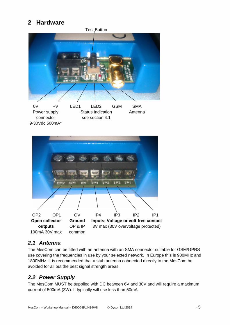
2 Hardware Test Button
0V +V LED1 LED2 GSM SMA
Power supply
connector
9-30Vdc 500mA*
Status Indication
see section 4.1
Antenna
OP2 OP1 OV IP4 IP3 IP2 IP1
Open collector
outputs
100mA 30V max
Ground
OP & IP
common
Inputs; Voltage or volt-free contact
3V max (30V overvoltage protected)
2.1 Antenna The MesCom can be fitted with an antenna with an SMA connector suitable for GSM/GPRS
use covering the frequencies in use by your selected network. In Europe this is 900MHz and
1800MHz. It is recommended that a stub antenna connected directly to the MesCom be
avoided for all but the best signal strength areas.
2.2 Power Supply The MesCom MUST be supplied with DC between 6V and 30V and will require a maximum
current of 500mA (3W). It typically will use less than 50mA.

MesCom – Workshop Manual – D6000-EU/H14/V8 © Dycon Ltd 2014 - 6
MesCom inputs are designed to interface with a wide variety of low-voltage devices, relays
and contacts, typically as used by monitoring sensors and alarm systems.
The MesCom power input is suitable for connection to a Dycon 1A power supply unit, or a
similar power source, which delivers a protected 6-30VDC voltage. It is not designed for
connection to industrial power sources without the provision of additional anti-surge
protection. Care should be taken to ensure correct polarity.
To avoid unnecessary notifications, all connection to inputs and outputs should be done
before powering the MesCom (alternatively use engineer-on-site mode, see sections 4.3).
2.3 Battery The battery is a 3,7v 640mAh Li-ion battery with built-in protect circuit and JST ZHR-2
connector.
See section 3.1 for how to connect the battery to the MesCom.
2.4 Indicators The MesCom has 3 LED indicators to show the current status and mode of operation - see
section 4.1 for more detail.
2.5 Inputs Inputs can measure up to 3V signals and can withstand voltage up to 30V. Voltage above
30V will damage the inputs.
Inputs can be configured as digital or analogue - see section 7.4 for more detail.
2.5.1 Digital Input Wiring Options
Eg. Signal from panels, switches and contacts etc.
Voltage present / absent
High going low
Low going high
Limiting resistor for
safety only
Pull down resistor
Pull down resistor
Pull up resistor
Ip1
Ip2
Ip3
Ip4
0V
Op1
Op2
10k Digital Voltage signal upto 30v
Current limiting Resistor
0V
Examples Alarm panel signals
Flood sensor
Volt-free contact
Open collector
SO, FET or Opto-couple
Pull up resistor
Pull up resistor
Pull up resistor
Ip1
Ip2
Ip3
Ip4
0V
Op1
Op2
Volt-free contact
Device to monitorSignal
0V
Examples Switch contacts and relays
Energy meter pulse output
Float switch

MesCom – Workshop Manual – D6000-EU/H14/V8 © Dycon Ltd 2014 - 7
2.5.2 Analogue Input Wiring Options
Analogue signal with a
maximum of 3V or less
can be connected
directly to the MesCom.
Pull up or down Ip1
Ip2
Ip3
Ip4
0V
Op1
Op2
Signal Max 3V
0V
Examples Low voltage analogue sensors
Including: temperature, pressure, weight, tank depth, flow rate
Analogue voltage inputs
above 3V need to be
scaled with resistors to
give a maximum of 3V to
the MesCom input.
The MesCom can then
be configured to scale
them back again.
R1 1KΩ
R2 = (max voltage/3 – 1)
× R1
Pull up or down Ip1
Ip2
Ip3
Ip4
0V
Op1
Op2
1k2
3k6
Analogue Voltage signal up to 12v
0V
Select resistor values depending on the maximum input voltage
Examples Supply voltage monitoring
Battery voltage monitoring
Analogue sensor.
Including: Temperature, pressure, weight, tank depth, flow rate
4-20mA Current inputs
Convert to a voltage with
a resistor.
R = 3/max current
Pull up or down Ip1
Ip2
Ip3
Ip4
0V
Op1
Op2
100
r Analogue Current signal upto 30mA
4-20mA Signal
Return
Examples 4-20mA Sensors
Including: Oil pressure, temperature, strain and stress.
Sender units and
thermistors can also be
connected to the
MesCom but these
sensors are non-linear
so should be used with
caution.
Pull Up resistor Connection dependant on individual
sensor and beyond the scope of this
manual.

MesCom – Workshop Manual – D6000-EU/H14/V8 © Dycon Ltd 2014 - 8
2.6 Outputs Outputs have a maximum switching capacity of 30v 100mA and are open drain type.
2.6.1 Output Wiring Options
MesCom outputs can be connected
directly to any device input that
accepts open drain/ open collector
signals.
For inputs requiring a voltage signal,
a pull up resistor will be required.
Ip1
Ip2
Ip3
Ip4
0V
Op1
Op2
Supply 30V max
0V
Connected device
Input
Pull up resistor if required by connected device
Small load of no greater than 30V
100mA can be connected directly to
the MesCom open drain output. Ip1
Ip2
Ip3
Ip4
0V
Op1
Op2
Supply Max 30v
Supply Ground
LoadMax 100mA
For higher power loads the output
will need to be connected to a relay.
The MesCom output is protected
against back EMF but we
recommend fitting an additional
reverse EMF protection diode for
added protection, as shown.
The relay can be of any type;
traditional, optical or solid state.
Using a relay also isolates the
MesCom from the load and is
recommended with cable runs of
longer than 1 metre.
Ip1
Ip2
Ip3
Ip4
0V
Op1
Op2
recommended reverse EMF protection diode
To
hig
hp
ow
er
load
Coil Supply Max 30v
Coil current Max 100mA
Coil Supply Ground
Relay

MesCom – Workshop Manual – D6000-EU/H14/V8 © Dycon Ltd 2014 - 9
3 Commissioning
3.1 Connect and Power-up Having found a suitable position to install the MesCom:
Connect to system sensors/relay etc. See connection details in section 2.5.
Connect the supplied stub antenna or any suitable GSM antenna with SMA connector.
Remove the lid by pulling a corner, being careful not to pull the battery if already
connected.
Insert SIM card as shown.
Make a note of the IMEI (product serial number)
which is required for the web configuration
manager.
Connect the battery to the small white 2 pin
connector near the power connector as shown on
the right.
The LED indicators should start to flash indicating the
unit is working. If the LEDs don’t flash it may be that the
battery is discharged, providing external power will
switch the MesCom on and charge the battery.
Connect a suitable supply to the power terminals being careful to observe polarity. Switch
the supply on.
After the MesCom has registered on a network, the LEDs give an indication of signal
strength - see section 4.2.2 for details of LED meaning.
3.2 Configure The MesCom is supplied with a default configuration (see section 8 for more details). For
MesCom2 devices, the best way to change this configuration is via the web configuration
service at http://www.dyconconfig.com/ (see section 13). Before using the configuration
service you will need to set the MesCom APN correctly. For the SIM card fitting, see section
16 for list of common APN settings.
Example:
9876 OPTION APN internet web web
Where 9876 is your password, the default password for a new MesCom is the last 4 digits of
the IMEI number. The response to this command will be ADDNUM successful/failed)
If your network doesn’t give a password/username leave them off the command.
Alternatively you can manually configure any/all parameters on a MesCom by SMS (see
section 5 for more details).
Before connecting a supply, ensure it is the correct voltage / current rating and the polarity is correct.
The MesCom is not fitted with a fuse or overvoltage / polarity
protection, incorrectly connecting a PSU will damage the device.

MesCom – Workshop Manual – D6000-EU/H14/V8 © Dycon Ltd 2014 - 10
4 Operation
4.1 General The primary function of the MesCom is to send a message when inputs change state. The
MesCom must know how to determine a change of state and where to send the message.
The MesCom can support 6 contacts to which it can send messages via SMS, GSM (data)
or GPRS, in various predefined formats. For more detail see section 5.
The MesCom is supplied in un-administered mode with no contacts pre-configured. In this
mode the MesCom will accept SMS commands from any phone number. The default
password is the last 4 digits of the IMEI number. To exit un-administered mode you must
add at least one contact with administrator level access, see section 4.4.
Contacts can be configured not to receive messages, for maintenance users or while on
holiday etc…
GPRS/GSM contacts can be a “send and forget” (eg uploading to web based data
concentration services see section 11) or connection based hosts - for more detail on
reporting, see section 12.
Points (inputs and outputs) can be configured to send messages to SMS contact,
GPRS/GSM contact or both.
Points can be configured to record their state at routine intervals and/or record every change
of state (section 7.4)
4.2 LEDs and Test Button
4.2.1 Power-up
On power-up the LED1 and LED2 (yellow and green respectively) will switch ON blinking
every 2 seconds (until the power sequence is complete).
Holding the TEST button while powering the MesCom allows you to perform some useful
tasks:
Hold for less than 5 seconds* – Clear the event log.
LED1 (yellow) will flash (2Hz).
Hold for more than 5 seconds* – Call configuration server (get most recent configuration).
LED2 (green) will flash (2Hz).
Release and press within 5 seconds* – Reload factory defaults (remove users and clear log).
LED1 (yellow) will flash quickly (10Hz).
* Time starts from when LED1 starts flashing and LED2 is off.

MesCom – Workshop Manual – D6000-EU/H14/V8 © Dycon Ltd 2014 - 11
4.2.2 Normal Operation
LED1 and LED2 indicate the GSM signal strength and device status:
LED2 (Green) LED1 (Yellow) Status
Off Off Power is off
On (blink) On (blink) Initialising (blinking off every 2s)
Off On Signal strength is low CSQ < 11
On On Signal strength is OK between 11 and 18
On Off Signal strength is good CSQ > 18
ignore Flash (4Hz) Call or notification in progress
Flash alt Flash alt Self-test in progress (1s each)
Flash alt Flash alt Fault condition (250ms each)
Blink 1min Off Power saving mode
ignore Blink 10sec Engineer on site mode
Flash sync Flash sync (2Hz) Test button press for between 5-10s
The signal strength thresholds (low and good) are fixed.
In normal operation the test button can be configured to do multiple things: these include
entering/exiting “Engineer on site” mode, overriding power saving mode, making a call,
sending a notification and sending a status report.
When TEST is pressed:
Power saving mode will be overridden for 15 minutes
Call to host initialled.** (POINT button CALL)
Notification to users.**(POINT button ALARM)
Hold TEST for 5 seconds: (LED1 and LED2 flash in sync)
Status report to all users.** (OPTION RINGMODE)
Exit “Engineer on site” mode.** (OPTION SUPPRESS)
Cancel the 15 minute-powered state above.
Hold TEST for 10 seconds:
Enter “Engineer on site” mode.** (OPTION SUPPRESS)
** Feature can be disabled/enabled by configuration
4.2.3 Radio Module Status
LED3 (Red) Status
Off Radio module is off
Flash (1s) Module is searching for network
Flash (3s) Module is registered on a network
On Module is currently in a call
4.3 “Engineer-on-site” Mode When in this mode, the MesCom will monitor all inputs and allow outputs to be changed but
will not generate notifications or trigger calls to the host. This mode should be used when
any work is being performed on the system.
“Engineer on site” input can be configured to any input - see section 7.7.22.
By default “Engineer on site” mode is entered holding the test button for longer than 10
second and exiting by holding the test button for 5-10 seconds.

MesCom – Workshop Manual – D6000-EU/H14/V8 © Dycon Ltd 2014 - 12
With the exception of configuring the input to be the TEST button (see section 4.2.2),
“Engineer on site” mode will be entered when the input goes high***. The mode will exit
when the input goes low or a timeout occurs.
*** The input state which activates “Engineer-on-site” mode is fixed.
The “Engineer on site” mode has a configurable maximum time; should this expire, the unit
will exit “Engineer on site” mode. “Engineer on site” mode can be re-activated by repeating
the entry process above.
“Engineer on site” timeout is configurable - see section 7.7.23.
“Engineer on site” mode can be activated and disabled by SMS - command OPTION
SUPPRESS – see command section 7.7.22.
4.4 Useful Commands Below are some commands that may be useful in day to day use. See section 5 for the full
range of commands available. Some of these commands will need administrator level
access.
4.4.1 Adding and Removing Users Example:
9876 ADDNUM +447·········
Where 9876 is your password, the default password for a new MesCom is the last 4 digits of
the IMEI number.
To remove a user you must use the REMOVE command:
Example:
9876 REMOVE +447·········
The phone number should be in international format (ie starting with a + symbol). If a
number is given and not in the user list, a fail message will be returned. If the number is
omitted, then the sender’s number will be removed from the user list.
4.4.2 Reading the Current Status
To find out the current status of an input or output, use the READ command.
Example:
9876 READ Input3
The command supports a request for up to 4 points at once. The keyword ALL can also be
used to return a list of all enabled points. Points can be their name or number: see section
1.1 for numbering details.
4.4.3 Changing an Output
To change an output, use the SWITCH command or the PULSE command depending on the
signal you want to produce.
Example:
9876 SWITCH OP2 ON
The SWITCH command supports an instruction for up to 3 points at once. Points can be
their name or number. The final value will be the value to set all outputs to - this final value
can be a state label for the first listed point, where Label0 = 0 and Label1..4 = threshold0..3.

MesCom – Workshop Manual – D6000-EU/H14/V8 © Dycon Ltd 2014 - 13
The SWITCH command can also be used to reset a counter/timer input. On other input
points the SWITCH command has no effect.
Example:
9876 PULSE OP2 ON 500 OFF
The PULSE requires 4 values: 1st the point name or number, 2nd initial value to set point to,
3rd delay in milliseconds before changing to final value, 4th final value to set point to.
Attempting to PULSE a point that isn’t an output will have no effect.
4.4.4 Disable Faulty Input
To disable an input should the sensor become faulty, you can use the DISABLE command:
Example:
9876 DISABLE input3
To reverse this action, use the ENABLE command:
Example:
9876 ENABLE input3
4.4.5 Temporary STOP/START User’s Notification
The STOP command is a universal command to stop getting text messages from an
automated system. This allows a person who has been accidently added to the unit to
disable the text message from the unit. Please note the STOP does not need to be preceded
with a password.
This command will stop you receiving any more notifications.
STOP
The STOP command also allows a user to temporarily disable messages to themselves, for
example when they are out of the country.
To re-start message use the START command:
Example:
9876 START
An administrator can view if a user has messages on stop with the VIEW command. The
START command can be configured to be administrator access only, forcing users to
contact the administrator to re-start them.
Example:
9876 VIEW USER ALL
This will output a list of all users and their settings.
An administrator can force a START on any user:
Example:
9876 START +447·········
Additionally to conform to automated text services best practice, the REMOVE command
can also be used without a password to remove the sender from the device.
This command will stop you receiving any more notifications.
REMOVE
Note: to remove users other than yourself, a password needs to be provided and you need
administrator access.

MesCom – Workshop Manual – D6000-EU/H14/V8 © Dycon Ltd 2014 - 14
5 Contacts Contacts can be SMS users’ or host/server’s addresses. The MesCom supports any
combination of up to 6.
A contact has a number of attributes to define how events will be transmitted to it and what
commands can be received from it.
In addition to the 6 User contacts, the MesCom has some system contacts. Some OPTION
commands may return ADDNUM Successful as confirmation they the command was
successful not the usual option value.
All types of users are added and removed in the same way.
Please Note contacts are handled differently in MesCom2 compared to the original
MesCom.
5.1 Contact Attributes List of contact attributes. When adding a contact, the parameters can be omitted. If included
the preceding parameter must also be included (for example if you want to set the access
level you must set the password) - see section System Default Contact Settings for system
default.
Address Where to send the Notification.
Maximum length 32 characters (no spaces)
Eg +447xxxxxxxxx
Password The contact’s password must be given when
sending commands to the MesCom.
Maximum length 48 characters (no spaces)
Please note: Passwords are case sensitive.
Eg 9876
Access Level The commands access level the user has,
see below.
0 = no commands.
6 = all commands.
Format The format of the message. 0 = no notifications.
1 = standard messages.
Transport The method used to send the notification. 4 = SMS.
Username Optional; may be required for connecting to
computer systems.
Maximum length 32 characters (no spaces)
5.1.1 Address
Phone number for CSD host and SMS users can be in local (07xxxxxxxxx) or international
format (+447xxxxxxxxx).
GPRS address is an IP address in numerical (eg 192.168.0.1) or name (eg
www.dyconsecurity.com) format and can be followed by a port number (eg 192.168.0.1:80).

MesCom – Workshop Manual – D6000-EU/H14/V8 © Dycon Ltd 2014 - 15
5.1.2 Password
Case sensitive.
Each contact has an individual password. To be prefixed to all incoming commands or
authenticate with a remote host. If left blank the system default will be used. From the factory
this default is the last 4 digits of the IMEI number (see label inside the MesCom).
5.1.3 Access Level
What command access level the contact has:
0 Receive - no commands are accepted from this user.
1 Read only – READ and PASSWORD commands accepted.
2 View – VIEW, READ and PASSWORD commands accepted.
3 Control – SWITCH, PULSE, VIEW, READ and PASSWORD commands accepted.
4 Service – As Administrator but without SWITCH and PULSE commands.
5 Server – All the features of Administrator but isn’t added to the Admin user count.
6 Administrator – Access too all commands.
5.1.4 Message Format
The message output format. Care should be taken to select the correct one for the contact.
Hosts will require a specific format and not all formats are suitable for SMS.
0 Do not use - Contact Empty.
1 No Notifications.
2 Standard message – it is recommended this format is used for SMS.
3, 4, 5, 6 Do not use.
7 Cosm/Xlivey web service.
8, 9 Do not use.
10 Fixed width text – to align display of many events on screen.
11 HTML – event will be given as a row in a HTML table.
12 Comma-separated values – for interpretation by computer.
13 Short message – without unit name or the time the event took place.
Only Formats 1,2,13 should be used with SMS; all others are for computer systems.
See section 6 for details of the different formats.

MesCom – Workshop Manual – D6000-EU/H14/V8 © Dycon Ltd 2014 - 16
5.1.5 Transport
If omitted, this is automatically selected based on the address but you may wish to override
the default TCP selection for server /host connections.
0 TCP
1 UDP
2 CSD
3 reserved
4 SMS
5 SMTP – special case, do not use.
6 APN – special case, do not use.
7 FTP – upload a file via FTP.
8 HTTP – upload events via HTTP PUT or POST methods (for Cosm etc).
5.2 New MesCom (un-administered mode) The MesCom is supplied in un-administered mode with no contacts pre-configured. In this
mode the MesCom will accept SMS commands from any phone number. The default
password is the last 4 digits of the IMEI number. The IMEI is printed on the radio module
inside the MesCom (scanning the quick code will also give you the IMEI) - see picture in
section 3.1.
To exit un-administered mode, you must add at least one contact with administrator level
access. Should you remove all administrators, the MesCom will revert to un-administered
mode.
Once in administered mode the MesCom will only accept commands from users on the
contact list. Should you wish to override this and allow any phone number to access the
MesCom with the default password, see OPTION CMDMODE command.
The first user added when in un-administered mode by default will be added as an
administrator. The default access level for contacts added while in administered mode is the
system default (factory default view <2>).
5.3 Adding a User The simplest method to add a new user is as follows:
9876 ADDNUM +447xxxxxxxxx
This will add the number +447xxxxxxxxx as a user with the unit’s default password. With
read only access unless there are no admin level users subscribed to the device.
9876 ADDNUM

MesCom – Workshop Manual – D6000-EU/H14/V8 © Dycon Ltd 2014 - 17
Will add the sender’s number as admin but this will only work if none of the users subscribed
to the MesCom are admin level. – ie subsequent users cannot add themselves with this
command.
9876 ADDNUM +447xxxxxxxxx <NewPassword> <Access> <Format> <Transport> <Username>
The ADDNUM command has been extended so all the attributes can be set - see section
7.2.6 for more detail.
Adding a user with the same address/phone number as a user already subscribed will
replace the previous user, resetting their password; a duplicate will not be created.
5.4 Removing a User The REMOVE command, along with the STOP command, are the only commands that do
not require a password to precede them. This is to comply with best practice to electronic
communication providing the users with an intuitive method to unsubscribe from automated
message.
REMOVE
Should an administrator wish to remove another user, they may do so by providing their
password and the address of the user. See section 7.2.5 for more detail.
9876 REMOVE +447xxxxxxxxx
5.5 Changing a Password Passwords can only be changed by the user themselves.
<oldPassword> PASSWORD <newPassword> <newPassword>
5.5.1 Password Recovery
Should a user forget their password, an administrator can re-create the user using the
ADDNUM command including a new password.
5.6 Stop Command The STOP command sets the sender’s message format to none so that they will not get any
more events messages. The user will still be subscribed to the MesCom.
STOP
To reverse this command, use the START or ADDNUM command.
5.7 Start Command The START command sets the sender’s format to Human so that they will get event
messages again.
9876 START +447xxxxxxxxx
Only administrators can provide the address parameter.
This command can be configured to be for administrator use only – thereby ensuring that an
administrator is aware that someone has stopped themselves from getting message.

MesCom – Workshop Manual – D6000-EU/H14/V8 © Dycon Ltd 2014 - 18
5.8 Viewing Current Contact List Administrators may wish to see who is subscribed to a MesCom to confirm people are still
getting message or to determine if there is space for extra users.
9876 VIEW USER ALL
This is an administrator only command.
5.8.1 View Response
Failed – if command is incorrect.
USER listing of the 6 user locations.
Each user location is either; “BlkContact” if the space in empty or
<address> <level> <format> <transport> <username>
if “username” is an empty field the text “blank” is inserted.
Eg.
MesCom: USER +447xxxxxxxxx 6 2 4 blank +447xxxxxxxxx 6 2 4 blank
cloud.nimbits.com:80 0 6 0 [email protected] BlkContact BlkContact BlkContact
Please note passwords are not listed.
5.9 Changing a Contact’s Access Level, Format etc… Administrators may change any of the parameters (Format, Access level, Transport) of a
user by re-creating them using the ADDNUM command. This will require the users’
password to be reset. See section 7.2.6 for more detail.
5.10 System Default Contact Settings The system defaults can be configured with the OPTION ACCOUNT command.
Factory system default
Address NA
Password Last 4 digits of the IMEI number
Access Level View <2>
Format Human <2>
Transport TCP <0> for IP address otherwise SMS <4>
Username Blank

MesCom – Workshop Manual – D6000-EU/H14/V8 © Dycon Ltd 2014 - 19
6 Notifications The primary purpose of the MesCom is to notify one or more users of a change of state. The
format of the notifications can be configured on a per user basis. The type of events that
generate a notification can also be configured. See section 7.5.4 for more details.
6.1 Format
1 Standard device point [type] state [value] time
MyGarage Temperature decreased to Low(5.00C) 24-08-2013,23:45:34
10 Fixed
Width
point state [value]
Temperature Low 5.0000C
11 HTML <tr><td>point</td><td>state</td><td>value</td></tr>
<tr><td>Temperature</td><td>Low</td><td>5.0000C</td></tr>
12 CSV point,state,value,time
Temperature,Low,5.0000C,2013-08-24T23:45:34.880
13 Short point [type] state [value]
Temperature decreased to Low(5.00C)
See section 5 for more detail about setting the message format.
Where:
Device Name given to MesCom (OPTION IDENT).
Point Name given to input/output (POINT PNAME).
Type Type of event, omitted for digital input/output, increase/decrease/counter overflow.
State Label given to level/state of input/output (POINT LEVELS) or counter raw value.
Value Scaled value of input, omitted for digital input/output. See section 7.5.3.
Time Time event was detected, style dependant of format.
Routine readings are preceded with “Status” eg:
MyGarage Status: Temperature Normal(18.00C) 24-08-2013,23:45:34
System events are preceded with “System Event”.
6.2 Event Types A point can be configured independently to generate 3 different types of event.
Alarm The value is moving away from normal, high to low or counter threshold crossed.
Restore The value is moving toward normal, low to high, or a counter has overflowed.
Routine A periodic reading of the value, useful for data logging and fault finding.
System An internal event generated by MesCom, independent of input and output status.
Alarm and Restore are controlled by the POINT ALARM parameter.
Routine are controlled by the OPTION LOGINT, POINT LOG and NLOG parameter.
System events are controlled by the OPTION SYSTEM and

MesCom – Workshop Manual – D6000-EU/H14/V8 © Dycon Ltd 2014 - 20
SYSACT parameters.
6.3 Restricting transmission Each point can be configured independently to determine which classes of users the event
will be sent to. SMS parameter allows events to be sent to SMS users (phone number).
UNSOL allows events to be sent to web-based data collection services. NLOG parameter
allows routine logs to be sent to SMS users if the LOG and SMS parameters are set. All
events will be available for a host to request but the CALL parameter allows an alarm or
restore event to trigger a call to the host server.

MesCom – Workshop Manual – D6000-EU/H14/V8 © Dycon Ltd 2014 - 21
7 Manual Commands While manual configuration is available, it is recommended that you use the MesCom
configuration manager http://www.dyconconfig.com/ - see section 13 for more detail.
All manual commands need to be sent to the MesCom from a subscribed user with a
suitable level of access (see section 5.1.1) and must be prefixed with that user’s password.
Example:
9876 READ ALL
Command Examples
HELP Provide help on commands and parameters
available
HELP COMMAND
HELP
ADDNUM Add a user to the MesCom ADDNUM +447xxxxxxxxx
REMOVE Remove a user REMOVE +447xxxxxxxxx
STOP Stop a user receiving any messages STOP
START Re-start message to a user START
DISABLE Stop all actions related to an input/output DISABLE Intruder
ENABLE Re-enable an input/output ENABLE Tank_Level
READ Read the current status of an input/output READ Temperature
READ ALL
SWITCH Change the state of an output SWITCH output2 OFF
PULSE Cause a pulse output PULSE op1 ON 1000 OFF
POINT Configure an input/output POINT input1 SMS yes
OPTION Configure a general setting in the MesCom OPTION PSAVE 3
VIEW View configuration VIEW OPTION WAKE
PASSWORD Change your password PASSWORD new new
FETCH Trigger the MesCom to retrieve a new
configuration from the configuration service
FETCH
CLEAR Clear all stored events CLEAR
CALLNOW Trigger the MesCom to make a call to a host CALLNOW
REPORT Trigger the MesCom to report the current status
to all users
REPORT
The following commands are only permitted from the terminal connection
SHOW Show the current input / output values SHOW
DEFAULT Change all internal setting to factory default DEFAULT
ECHO Switch local terminal character echo on/off ECHO
DEBUG Switch local terminal debug message on/off DEBUG
RESET Restart the MesCom RESET
FTEST Enter factory test mode FTEST
Some commands can have multiple parameters and settings: these are READ, SWITCH,
DISABLE, ENABLE, OPTION, POINT. See individual commands for more detail.
Example:
9876 OPTION IDENT MyGarage PSAVE 2 WAKE 180 SLEEP 60
Important: Each command, keyword and value MUST be separated by a space.
Important: Every parameter MUST have a value.

MesCom – Workshop Manual – D6000-EU/H14/V8 © Dycon Ltd 2014 - 22
Passwords are case sensitive and although commands, keywords and labels are not case
sensitive, labels will be displayed in the case given when set.
The command format is <password> <command> <optional variables …>
If an incorrect password is sent or the command is not recognised, including commands
above a user’s access level, the MesCom will not respond. The MesCom will NOT reply with
an error or fail response. A lack of response should be interpreted as a failure. This is to
avoid responding to messages from network operators and incorrect numbers.
7.1 Basic Configuration
7.1.1 General Configuration
MesCom settings you may wish to change are included below; see section 7.7 for a full list.
IDENT The unit’s identifying name a string (no spaces) of up-to 24
characters
PSAVE The power saving
mode
0 – never enter power saving (least power saving)
1 – save power when battery is low
2 – save power when using battery
3 – save power whenever possible (most power saving)
WAKE The time the MesCom keeps the radio
powered after an action occurs
Number of seconds (minimum 100s,
max 32767)
SLEEP The maximum time the radio is
powered off between check for new text
messages
Number of minutes (minimum 5
minutes, max 32767)
LOGINT The routine logging interval Number of minutes (0 disables max
32767)
SYNC The synchronisation time for routine
logging
Number of minutes past midnight (eg
300 = 5am 1440 >= disabled)
PULLUP Inputs are pulled up or down when the
signal is disconnected.
UP/DOWN YES/NO TRUE/FALSE
(Pull up for volt-free contacts)
Example:
9876 OPTION IDENT MyGarage PSAVE 2 WAKE 180 SLEEP 60
9876 OPTION LOGINT 180 SYNC 300 PULLUP YES
Please Note: All labels MUST contain NO spaces - we suggest underscore is used instead.

MesCom – Workshop Manual – D6000-EU/H14/V8 © Dycon Ltd 2014 - 23
7.1.2 Configure Inputs
Inputs can be configured as Digital, Analogue, Timer or Counter.
See below for the main settings for each point; see section 7.5 for a full list.
TYPE Point type 0 – Digital input
1 – Timer (digital input)
2 – Counter (digital input)
3 – 16bit analogue input
4 – Reserved
5 – Digital output
6+ – Reserved
DEBOUNCE Digital debounce or analogue
averaging
Number of samples (min 1, max
256)
THRES 4 values state threshold values 0.0 to 3.0 (volts) or in format
#nnnnn to be ADC count
HYST Threshold hysteresis 0.0 to 3.0 (volts) or in format
#nnnnn to be ADC count
PNAME The point identifying name A string (no spaces) of up to 24
characters
LEVELS 5 values, the name to be applied to the
point’s state
A string (no spaces) of up to 16
characters
READMIN Point scaling value, minimum input
voltage
0.0 to 3.0 (volts) or in format
#nnnnn to be ADC count
READMAX Point scaling value, maximum input
voltage
0.0 to 3.0 (volts) or in format
#nnnnn to be ADC count
DISPMIN Point scaling value, minimum scaled
value – corresponding to VOLTMIN
Decimal number (min -9999.9999
max +9999.9999)
DISPMAX Point scaling value, maximum scaled
value – corresponding to VOLTMAX
Decimal number
SUFFIX Suffix to add to scaled value A string (no spaces) of up to 8
characters
Digital Example:
9876 POINT Input1 TYPE 0 DEBOUNCE 10 THRES 0.5 3 3 3 HYST 2
9876 POINT Input1 PNAME Door LEVELS Open Closed na na na
Analogue Example:
9876 POINT Input2 TYPE 3 DEBOUNCE 10 THRES 0.2 1.0 2.0 2.8 HYST 0.1
9876 POINT Input2 PNAME WaterLevel LEVELS Empty Low Normal High Full SUFFIX m
9876 POINT Input2 READMIN 0.4 READMAX 2.0 DISPMIN 0.0 DISPMAX 1.5
Repeat for Input3, Input4 as required.
Please Note: All labels MUST contain NO spaces - we suggest underscore is used instead.
7.1.3 Configure Outputs
Outputs are configured with the same command structure as inputs:
9876 POINT OP1 TYPE 5 DEBOUNCE 0 THRES 3.0 3.0 3.0 3.0 HYST 0
9876 POINT OP1 PNAME lights LEVELS ON OFF na na na
Repeat for OP2 as required.
Please Note: All labels MUST contain NO spaces - we suggest underscore is used instead.

MesCom – Workshop Manual – D6000-EU/H14/V8 © Dycon Ltd 2014 - 24
7.1.4 Confirm Settings
Settings can be confirmed with the VIEW command:
9876 VIEW OPTION ALL
9876 VIEW POINT input1 ALL
Repeat for Input2, Input3, Input4, OP1, OP2 as required.
7.1.5 Adding Users
To add a user you must use the ADDNUM command:
9876 ADDNUM +447·········
The phone number should be in international format (ie starting with a + symbol). If there is
no space in the user list for another number (max 4), a fail message will be returned. If the
number is omitted, then the sender’s number will be added to the user list. Adding a number
that is already on the user list will not create a duplicate.
7.2 Commands
7.2.1 READ
Report the latest status of the listed points. Access Level: Read
9876 READ <pointA> <pointB> <pointC> <pointD>
<pointA> Input or output name or number. ALL supported: Yes
<pointB> Optional Input or output name or number. Up to 4 points
<pointC> Optional Input or output name or number.
<pointD> Optional Input or output name or number.
9876 READ Input1 Battery Request the value of Input1 and Battery
MesCom: Input1: Clear Battery: Good(4.1V)
04/04/12,16:15:25
9876 READ ALL Request the value of all enabled inputs and outputs
MesCom: Power: On(12.04V) Battery: Good(4.1V)
Button: Clear Temperature: Norm(22.12C) Input1:
Clear Input2: Clear Input3: Clear Input4: Clear
Op1: On Op2: Off 04/04/12,16:15:25
9876 READ 6 7 8 Request the value of points 6, 7 and 8
MesCom: Input1: Clear Input2: Clear Input3: Clear
04/04/12,16:15:25

MesCom – Workshop Manual – D6000-EU/H14/V8 © Dycon Ltd 2014 - 25
7.2.2 SWITCH
Change the start of an output and report the latest status of the
listed points.
Access Level: Control
9876 SWITCH <pointA> <pointB> <pointC> <value>
<pointA> Output name or number. ALL supported: No
<pointB> Optional output name or number. Upto 3 points
<pointC> Optional output name or number.
<value> Value to set the output to, state name can also be
used.
9876 SWITCH Op1 Op2 Off Set Op1 and Op2 to the Off state
MesCom: Op1: Off Op2: Off 04/04/12,16:15:25
9876 SWITCH Op1 Default action toggle Op1 (if on switch off and vice versa)
MesCom: Op1: On 04/04/12,16:15:25
9876 SWITCH 10 11 1 Set point 10 and 11 to a value of 1
MesCom: Op1: On Op2: On 04/04/12,16:15:25
9876 SWITCH Op1 elephant Op1 doesn’t have a state labels elephant
MesCom: Failed 04/04/12,16:15:25
Notes Attempting to switch an input will have no effect unless it is a timer/counter in
which case it will set the input value to the given number.
Outputs can be configured to notify on changes so all users will get a message,
therefore when sending this command it is likely you will get multiple responses.
If the last value is not a number or a valid state name for the first input, then a
fail message will be returned by the MesCom.
If only a single point is given with no value, the default action is to toggle the
output (if on switch off and vice versa).

MesCom – Workshop Manual – D6000-EU/H14/V8 © Dycon Ltd 2014 - 26
7.2.3 PULSE
Switch an output to a value and followed by a time delay switch
an output to a second value. Report the status of the given point
(this will typically be before the time delay has occurred).
Access Level: Control
9876 SWITCH <point> <valueA> <delay> <valueB>
<point> Output name or number. ALL supported: No
<valueA> Initial value to set the output to, state name can also
be used.
1 point only
<delay> Delay in milliseconds before changing output to
<valueB> Minimum 20ms, maximum 65000ms.
<valueB> Final value to set the output to, state name can also
be used.
9876 PULSE Op1 Off 1500 On Set point Op1 Off then 1.5 seconds later set it to On
MesCom: Op1: Off 04/04/12,16:15:25
9876 PULSE Op1 Default pulse on Op1 On 1second Off
MesCom: Op1: On 04/04/12,16:15:25
9876 PULSE 11 0 2000 1 Set point 11 to 0 then 2 seconds later set to 1
MesCom: Op2: Off 04/04/12,16:15:25
9876 PULSE input1 0 200 1 Input1 isn’t an output point
MesCom: Failed 04/04/12,16:15:25
Notes Attempting to switch an input will have no effect.
Outputs can be configured to notify on changes so all users will get a message.
Therefore when sending this command it is likely you will get multiple
responses.
If any of the parameters are not valid, then a fail message will be returned by
the MesCom.
If only an output point is specified, then the default pulse of “On 1000ms Off”
will be triggered.

MesCom – Workshop Manual – D6000-EU/H14/V8 © Dycon Ltd 2014 - 27
7.2.4 REMOVE
Remove the sender’s number from the user list. Access Level: RECIEVE
REMOVE
Anything after REMOVE will be ignored. ALL supported: No
REMOVE Remove the sender number
MesCom: REMOVE Successful 04/04/12,16:15:25
9876 REMOVE Remove the sender number
MesCom: REMOVE Successful 04/04/12,16:15:25
Notes This command will stop you receiving any more notifications.
7.2.5 REMOVE user
Remove a specified user from the subscribers’ list. Access Level:
Administrator
9876 REMOVE <address>
<address> The address of the user - for SMS users this is their
number phone.
ALL supported: No
1 user per command
9876 REMOVE +447xxxxxxxxx Remove the number +447xxxxxxxxx
MesCom: REMOVE Successful 04/04/12,16:15:25
9876 REMOVE 07xxxxxxxxx Remove the number 07xxxxxxxxx
MesCom: REMOVE Successful 04/04/12,16:15:25
Notes This command will stop you receiving any more notifications.
All addresses MUST be the same as they are stored on the MesCom - use
VIEW USER ALL to see how they are stored and who is subscribed.
If there is no user with that address, a fail message will be returned by the
MesCom.

MesCom – Workshop Manual – D6000-EU/H14/V8 © Dycon Ltd 2014 - 28
7.2.6 ADDNUM
Add a user to the subscribed list. Access Level:
Administrator
9876 ADDNUM <address> <password> <level> <format> <transport> <username>
<address> The address of the user - for SMS users this is
their number phone.
ALL supported: No
<password> Give the user a password
default: last 4 digits of IMEI
1 user per command
<level> Specify users access level
default: Read Only
<format> The message output format
Default: standard
<transport> What method to send the message on
Default: dependant on address given
<username> Specify a username only used by some server
systems
9876 ADDNUM Add the sender’s number to the users list
MesCom: ADDNUM Successful 04/04/12,16:15:25
9876 ADDNUM +447xxxxxxxxx
newpassword 6 12 Add the number to the contact list with a password of
“newpassword”, with administrator level access and the
“short” message format.
MesCom: ADDNUM Successful 04/04/12,16:15:25
9876 ADDNUM +447xxxxxxxxx Add the number to the contact list with default settings
MesCom: ADDNUM Successful 04/04/12,16:15:25
Notes See User section for more detail about the parameters.
The subscribed user can be viewed with the VIEW USER ALL command.
The MesCom supports a limited number of users - when this limit is reached
the ADDNUM command will return a failed message.
If any of the parameters are not valid, then a fail message will be returned by
the MesCom.
All parameters can be omitted, this will add the sender’s number. This will
only work if no currently subscribed users have Administrators access.

MesCom – Workshop Manual – D6000-EU/H14/V8 © Dycon Ltd 2014 - 29
7.2.7 DISABLE
Disable the listed points, provides a quick way to stop a faulty
point triggering messages.
Access Level:
Administrator
9876 DISABLE <pointA> <pointB> <pointC> <pointD>
<pointA> Input or output name or number. ALL supported: Yes
<pointB> Optional Input or output name or number. Up to 4 points
<pointC> Optional Input or output name or number.
<pointD> Optional Input or output name or number.
9876 DISABLE Input1 Op2 Disable points Input1 and Op2
MesCom: DISABLE Successful 04/04/12,16:15:25
9876 DISABLE 8 10 Disable points 8 and 10
MesCom: DISABLE Successful 04/04/12,16:15:25
Notes If a parameter is invalid, the MesCom will stop processing the list (points
before the invalid entry will be disabled).
The reverse of this command is ENABLE.
A point can also be disabled with the command POINT input1 ENABLED NO.
7.2.8 ENABLE
Enable the listed points, reverses the action of DISABLE
command.
Access Level:
Administrator
9876 ENABLE <pointA> <pointB> <pointC> <pointD>
<pointA> Input or output name or number, ALL supported: Yes
<pointB> Optional input or output name or number, Up to 4 points
<pointC> Optional input or output name or number,
<pointD> Optional input or output name or number,
9876 ENABLE Input1 Op2 Enable points Input1 and Op2
MesCom: ENABLE Successful 04/04/12,16:15:25
9876 ENABLE 8 10 Enable points 8 and 10
MesCom: ENABLE Successful 04/04/12,16:15:25
Notes If a parameter is invalid, the MesCom will stop processing the list (points
before the invalid entry will be enabled).
The reverse of this command is DISABLE.
A point can also be enabled with the command POINT input1 ENABLED YES

MesCom – Workshop Manual – D6000-EU/H14/V8 © Dycon Ltd 2014 - 30
7.2.9 HELP
Help function: identity device model / list point names / list
commands / list point settings names/ list users / list option
settings names.
Access Level: Read
9876 HELP <category>
<category> Optional category of help needed
COMMAND – a list of commands
OPTION – all the OPTION parameters
POINT – all the POINT parameters
LIST – all the point names
ALL supported: No
9876 HELP Identify unit and basic help
MesCom: C003 MesCom v2.00 COMMAND OPTION POINT
LIST 04/04/12,16:15:25
9876 HELP COMMAND List commands available
MesCom: HELP STOP START REMOVE ADDNUM ENABLE
DISABLE PASSWORD SWITCH POINT READ VIEW PULSE
OPTION 04/04/12,16:15:25
7.2.10 PASSWORD
Change your password. Access Level: Read
9876 PASSWORD <newPassword> <newPassword>
<newPassword> The replacement password, this should be
entered twice.
ALL supported: No
9876 PASSWORD 123456 123456 Change password to 123456
MesCom: PASSWORD Successful 04/04/12,16:15:25
9876 PASSWORD 123456 12345 Passwords do not match
MesCom: PASSWORD Failed 04/04/12,16:15:25
Notes Passwords are case sensitive.
If the 2 new passwords are not identical, the password will not be
changed.
The REMOVE keyword saves a blank password and therefore will not be
required. To reinstate a password, the command should be PASSWORD
newWord newWord.

MesCom – Workshop Manual – D6000-EU/H14/V8 © Dycon Ltd 2014 - 31
7.2.11 STOP
Stop the sender’s number receiving any more notifications –
number will remain in user list to allow use of start command.
Access Level: Any
STOP
Anything after REMOVE will be ignored ALL supported: No
STOP Stop receiving messages – no response from MesCom
9876 STOP Stop receiving messages – no response from MesCom
Notes This command will stop you receiving any more notifications.
The reverse of this command is START.
7.2.12 START
Re-start notifications to a user if previously stopped. Access Level: Any
9876 START
ALL supported: No
1 user per command
9876 START restart notification to the senders number
MesCom: START Successful 04/04/12,16:15:25
Notes The reverse of this command is STOP.
If the sender is not a user, a fail message will be returned by the MesCom.
The MesCom can be configured to restrict the START command to
administrator’s use only - see section 7.7.25.
7.2.13 START user
Re-start notifications to a user if previously stopped. Access Level:
Administrator
9876 START <address> <format>
<address> The address of the user. For SMS users this is
their number phone in international format ie
+447…
ALL supported: No
<format> Optional parameter to set the user’s message
format.
1 user per command
9876 START +447xxxxxxxxx restart notification to +447xxxxxxxxx
MesCom: START Successful 04/04/12,16:15:25
9876 START +447xxxxxxxxx 13 restart notification to +447xxxxxxxxx with format 13
(short message)
MesCom: START Successful 04/04/12,16:15:25
Notes see START

MesCom – Workshop Manual – D6000-EU/H14/V8 © Dycon Ltd 2014 - 32
7.2.14 VIEW
Read back a setting of the MesCom. Access Level: Read
9876 VIEW <category> <point> <parameterA> <parameterB> <parameterC> <parameterD>
<category> Type of item to view;
POINT – view a given points settings
OPTION – view general options
USER – view subscribed users (administrator level)
LIST – view a list of point names
COUNTER – view the call and SMS counters
ALL supported: Yes
<point> If category is POINT; Input or output name or
number. Otherwise this field should be omitted.
The ALL keyword is not a valid point name.
Upto 4 parameters
<parameterA> Parameter you wish to view.
<parameterB> Optional setting you wish to view.
<parameterC> Optional setting you wish to view.
<parameterD> Optional setting you wish to view.
9876 VIEW LIST View a list of all point names
MesCom: Modem Button Power Battery Temperature
Input1 Input2 Input3 Input4 Op1 Op2
04/04/12,16:15:25
9876 VIEW USER ALL View a list of all (6) users (administrator level only)
MesCom: USER +447xxxxxxxxx 6 2 4 blank
+447xxxxxxxxx 6 2 4 blank cloud.nimbits.com:80 0
6 0 [email protected] BlkContact BlkContact
BlkContact 04/04/12,16:15:25
9876 VIEW POINT input1 TYPE View the TYPE parameter of input1
MesCom: Input1: TYPE: 0 04/04/12,16:15:25
9876 VIEW OPTION ALL View all general options settings
MesCom: … 04/04/12,16:15:25
9876 VIEW COUNTER SMS The counters for SMS (today,outgoing,incoming,failed)
MesCom: SMS:2,32,1,1 04/04/12,16:15:25
Notes If any of the parameters are not valid, then a fail message will be returned
by the MesCom.
USER category requires administrator access. Response format is;
<address> <level> <format> <transport> <username>
“BlkContact” is inserted for each empty user slot
“blank” is inserted in any blank fields.
MesCom – Workshop Manual – D6000-EU/H14/V8 © Dycon Ltd 2014 - 33
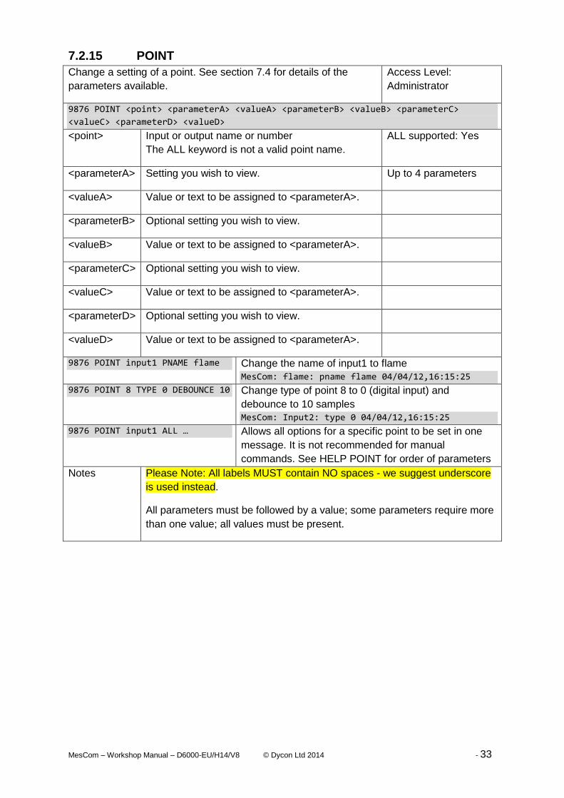
7.2.15 POINT
Change a setting of a point. See section 7.4 for details of the
parameters available.
Access Level:
Administrator
9876 POINT <point> <parameterA> <valueA> <parameterB> <valueB> <parameterC>
<valueC> <parameterD> <valueD>
<point> Input or output name or number
The ALL keyword is not a valid point name.
ALL supported: Yes
<parameterA> Setting you wish to view. Up to 4 parameters
<valueA> Value or text to be assigned to <parameterA>.
<parameterB> Optional setting you wish to view.
<valueB> Value or text to be assigned to <parameterA>.
<parameterC> Optional setting you wish to view.
<valueC> Value or text to be assigned to <parameterA>.
<parameterD> Optional setting you wish to view.
<valueD> Value or text to be assigned to <parameterA>.
9876 POINT input1 PNAME flame Change the name of input1 to flame
MesCom: flame: pname flame 04/04/12,16:15:25
9876 POINT 8 TYPE 0 DEBOUNCE 10 Change type of point 8 to 0 (digital input) and
debounce to 10 samples
MesCom: Input2: type 0 04/04/12,16:15:25
9876 POINT input1 ALL … Allows all options for a specific point to be set in one
message. It is not recommended for manual
commands. See HELP POINT for order of parameters
Notes Please Note: All labels MUST contain NO spaces - we suggest underscore
is used instead.
All parameters must be followed by a value; some parameters require more
than one value; all values must be present.

MesCom – Workshop Manual – D6000-EU/H14/V8 © Dycon Ltd 2014 - 34
7.2.16 OPTION
Change a general MesCom setting. See section 7.7 for details of
the parameters available.
Access Level:
Administrator
9876 OPTION <parameterA> <valueA> <parameterB> <valueB> <parameterC> <valueC>
<parameterD> <valueD>
<parameterA> Setting you wish to view. ALL supported: Yes
<valueA> Up to 4 parameters
<parameterB> Optional setting you wish to view.
<valueB>
<parameterC> Optional setting you wish to view.
<valueC>
<parameterD> Optional setting you wish to view.
<valueD>
9876 OPTION PSAVE 2 WAKE 120 Enter low power mode when powered by battery, delay
switching to low power for 120 seconds after every
event.
MesCom: OPTION: PSAVE 2 WAKE 120
04/04/12,16:15:25
9876 OPTION ALL … Allows all general options to be set in one message. It
is not recommended for manual commands. See HELP
OPTION for order of parameters.
Notes Please Note: All labels MUST contain NO spaces - we suggest underscore
is used instead.
All parameters must be followed by a value; some parameters require more
than one value; all values must be present.
7.2.17 FETCH
Connect to the configuration service and fetch the latest
configuration file.
Access Level:
Administrator
9876 FETCH
ALL supported: No
9876 FETCH MesCom retrieve a new configuration file without error
MesCom: FETCH Successful 04/04/12,16:15:25
9876 FETCH MesCom failed to download file or file had errors.
MesCom: FETCH failed 04/04/12,16:15:25
Notes The command will take a few minutes to complete.

MesCom – Workshop Manual – D6000-EU/H14/V8 © Dycon Ltd 2014 - 35
7.2.18 CLEAR
Clear the event log. Access Level:
Administrator
9876 CLEAR
ALL supported: No
9876 CLEAR All events in log cleared – ie will not send notifications.
MesCom: CLEAR Successful 04/04/12,16:15:25
Notes The command will take several seconds to complete.
The log will be cleared and a Clear Log event will be created.
7.2.19 CALLNOW
Force the MesCom to make a call/connection to the host server. Access Level:
Administrator
9876 CALLNOW
ALL supported: No
9876 CALLNOW Trigger a call to the configured host.
MesCom: CALLNOW Successful 04/04/12,16:15:25
Notes The command will wait for the call to host to command and report if it was
successful or failed.
7.2.20 REPORT
Force the MesCom to report to all users the current input/output
status.
Access Level:
Administrator
9876 REPORT
ALL supported: No
9876 REPORT Status report will be sent to all users
MesCom: REPORT Successful 04/04/12,16:15:25
Notes Command creates an event that in turn will trigger a status notification to be
sent to all.

MesCom – Workshop Manual – D6000-EU/H14/V8 © Dycon Ltd 2014 - 36
7.3 Terminal Commands The terminal connection gives the user administrator access. The terminal interface has no
password preceding the commands. All command responses exclude the device’s name and
date. Please contact Dycon for more details on using the terminal interface.
The following additional Terminal commands are for expert use only.
7.3.1 SHOW
Show the current point values (continuously updated). Access Level: Terminal
SHOW <type>
<type> ALL supported: YES
SHOW Show scaled values of enabled points.
SHOW RAW Show raw values of enabled points.
SHOW ALL Show raw values of all points.
Notes Sending any character to the terminal will exit this mode.
7.3.2 DEFAULT
Reset the device to default settings. Access Level: Terminal
DEFAULT
ALL supported: No
DEFAULT Settings have been restored to the factory defaults.
Notes It is recommended to perform a RESET of the MesCom after performing
this command as some settings are only loaded at power up.
7.3.3 ECHO
Enable/disable local echo on the terminal port. Access Level: Terminal
ECHO <state>
<state> ALL supported: No
ECHO ON Characters send to the MesCom will be echoed back to the terminal.
ECHO OFF Character send to the MesCom will NOT be echoed back to the terminal.
Notes

MesCom – Workshop Manual – D6000-EU/H14/V8 © Dycon Ltd 2014 - 37
7.3.4 DEBUG
Enable/disable the current debug output to the terminal. Access Level: Terminal
DEBUG <state>
<state> ALL supported: No
DEBUG ON Debug message will be displayed on the terminal.
DEBUG OFF Terminal Debug message are temporarily suspended.
Notes
7.3.5 RESET
Restart the MesCom without needing to remove power from the
device.
Access Level: Terminal
RESET
ALL supported: No
RESET No response to this command.
Notes No response to this command – MesCom will reboot and output version
number to the terminal.
7.3.6 LOG
Restart the MesCom without needing to remove power from the
device.
Access Level: Terminal
LOG <log position> <number of logs>
ALL supported: Yes
LOG Display all logs that have not yet been transmitted to a host.
LOG ALL Display all valid logs in NVM even if they have been transmitted.
LOG 123 10 Display any valid logs in position 123-132 (10logs).
Notes Only valid logs will be displayed.

MesCom – Workshop Manual – D6000-EU/H14/V8 © Dycon Ltd 2014 - 38
7.4 Input and Output Types The MesCom treats all inputs and outputs in a similar manor. They are collectively referred
to as points and their specific behaviour is controlled by the individual TYPE parameter.
The options for the TYPE parameter are:- 0 – Digital input
1 – Timer (digital input)
2 – Counter (digital input)
3 – 16bit Analogue input
4 – Reserved
5 – Digital output
6 – Reserved
7 – Reserved
All points can be configured as any one of these types. Care must be taken to assign
physical outputs as output type and inputs as input types. This flexibility is to allow for future
expansion of the system.
The different types make use of the 4 threshold levels and state labels in different ways - see
descriptions below.
When the TYPE parameter is set, other point parameters will be set to the default for that
point type. See section 8.3 for a list of the parameters changed and what they are changed
to.
Alarm messages (SMS notifications) can be suppress by the OPTION MAXSKIP setting if a
point changed state multiple times without any other point changing state. This is highlight
the end state of a point and reduce unwanted SMS messages, The Default if to skip up to 8
events but this can be reduced to zero should the user wish to receive all events.

MesCom – Workshop Manual – D6000-EU/H14/V8 © Dycon Ltd 2014 - 39
7.4.1 Analogue Input
Full
High
Normal
Low
Empty
Hysteresis
BottomThreshold
LowThreshold
HighThreshold
TopThreshold
Inp
ut
Valu
e
0v
3.0v
Decre
ased
to
Em
pty
Inc
reased
to
Lo
wIn
cre
ased
to
No
rmal
Inc
reased
to
Hig
h
Inc
reased
to
Fu
ll
Decre
ased
to
Hig
h
Decre
ased
to
No
rmal
Decre
ased
to
Lo
w
The input voltage reading is averaged* and then compared to the 4 threshold levels to
determine which of the 5 states the input is in. The 5 states can be given labels - in the
diagram these are Empty, Low, Normal, High, Full.
9876 POINT Input1 TYPE 3
9876 POINT Input1 THRES 0.2 1.0 2.0 2.8
9876 POINT Input1 LEVELS Empty Low Normal High Full
9876 POINT Input1 AVERAGE 20
Threshold values are input voltage values in the range 0.0000 to 3.0000.
An input can be configured to create alarm events any time the state changes, only when
moving away from normal (fault), only when moving toward normal (restore) or no alarms.
See diagram, black dot moving away, white dot moving toward ‘Normal’.
9876 POINT Input1 ALARM fault
Hysteresis can be applied to the Threshold levels. See diagram above, hysteresis allows an
input to fluctuate around a threshold with causing repeated notifications. For the 2 thresholds
above ‘Normal’ the hysteresis is applied when the signal is dropped (toward ‘normal’), in
effect making the threshold (threshold – hysteresis). For the 2 thresholds below ‘Normal’ the
hysteresis is applied when the signal is rising (toward ‘normal’), in effect making the
threshold (threshold + hysteresis). The hysteresis value is applied to all thresholds.
9876 POINT Input1 HYST 0.1

MesCom – Workshop Manual – D6000-EU/H14/V8 © Dycon Ltd 2014 - 40
*Average is a moving average calculation based on the given number of samples.
InputValue = ((n-1) x oldInputValue + newReading) / n
See section 7.5 for more detail.
Please Note: the AVERAGE and DEBOUNCE keywords are interchangeable; a point will
either use the value as number of samples to average or number of samples to debounce
depending on the input type.
The LEVELS labels each have a maximum of 16 characters – no spaces.
7.4.2 Digital Input
BottomThreshold
On
Off
Hysteresis
Inp
ut
Valu
e
0v
3.0v
Off O
nOffO
n
7.4.2.1 Schmitt Input / Dead Zone Input
On
Off
Hysteresis
BottomThreshold
Inp
ut
Valu
e
0v
3.0v
Off O
n
Input voltage reading is compared to the threshold to determine which state the input is in.
The reading state is then debounced and only once the debounce criteria* is met, does the
input state change.
The digital input requires one threshold but due to the universal nature of the MesCom point
system, all 4 thresholds need to be configured. The first threshold is used - the others are

MesCom – Workshop Manual – D6000-EU/H14/V8 © Dycon Ltd 2014 - 41
ignored when the input is configured as a digital input. The state labels are the first 2 labels,
Off and On in the diagram.
9876 POINT Input2 TYPE 0
9876 POINT Input2 THRES 1.0 3.0 3.0 3.0
9876 POINT Input2 LEVELS Off On Na Na Na
9876 POINT Input2 DEBOUNCE 20
Threshold values are input voltage values in the range 0.0000 to 3.0000.
An input can be configured to create alarm events on any state change; only high to low
(negative edge), only low to high (positive edge) or no alarms. See diagram, black dot
negative, white dot moving positive.
9876 POINT Input2 ALARM pos
Hysteresis can be applied to the threshold level to create a digital input with a dead zone,
See diagram. The Off level is the threshold value; the On value is (Threshold + Hysteresis).
9876 POINT Input2 HYST 0.1
*Debounce algorithm: the new reading has got to be in the same state for N samples before
a change of state is registered. See section 7.5 for more detail.
Please Note: the AVERAGE and DEBOUNCE keywords are interchangeable; a point will
either use the value as number of samples to average or number of samples to debounce
depending on the input type.

MesCom – Workshop Manual – D6000-EU/H14/V8 © Dycon Ltd 2014 - 42
7.4.3 Counter Input
On
Off
Hysteresis
BottomThreshold
Inp
ut
Valu
e
0v
3.0v
Off
On
Off
On
Off
On
Off
On
Off
Dec
reas
ed to
Ove
rflo
w
LowThreshold
Co
un
ter
Valu
e
0
65535
Incr
ease
to T
hresh
old
Can be used to count the number of times an input has been activated. This input uses the
digital input method to determine the input state. If this changes in the selected direction
(positive or negative edge), then the counter is increased by 1 count.
The counter input requires three thresholds but due to the universal nature of the MesCom
point system, all 4 thresholds need to be configured. The first threshold is used for digital
input filter, the second is the counter threshold, and the third is the overflow threshold. Two
labels are used, the first for Overflow events and second for Threshold events.
9876 POINT Input3 TYPE 1
9876 POINT Input3 COUNT pos
9876 POINT Input3 THRES 0.5 #2000 #5000 3.0
9876 POINT Input3 LEVELS Overflow Threshold na na na
9876 POINT Input3 DEBOUNCE 20
Where first value is the digital input threshold, the second value is the count threshold and
the third is the overflow threshold (maximum count value).
# Signifies a raw count value and not a scaled voltage value.
Should an increment cause the value to reach the threshold value, then a fault alarm can be
created. Additional when the counter reaches the overflow value a restore alarm can be
created. See diagram, black dot overflow (restore), white dot moving threshold (fault).
9876 POINT Input3 ALARM both
Hysteresis can be applied the same as digital inputs:
9876 POINT Input2 HYST 0.1

MesCom – Workshop Manual – D6000-EU/H14/V8 © Dycon Ltd 2014 - 43
7.4.4 Timer
On
Off
Hysteresis
BottomThreshold
Inp
ut
Valu
e
0v
3.0v
Off
On
Off
On
Off
On
Off
On
Off
Dec
reas
ed to
Ove
rflo
w
LowThreshold
Co
un
ter
Valu
e
0
65535
Incr
ease
to T
hresh
old
Can be used to time how long an input is in the specified state. This input uses the digital
input method to determine the input state whenever the input is sampled, and it is in the
specified state, the sample counter is increased. The Input value increases by 1 for each
accumulated second the input is in the specified state.
The timer input requires two thresholds but due to the universal nature of the MesCom point
system all 4 thresholds need to be configured. The first threshold is used for digital input
filter the second is the timer threshold. Two labels are used the first for Overflow events and
second for Threshold events.
9876 POINT Input3 TYPE 2
9876 POINT Input3 COUNT on
9876 POINT Input3 THRES 0.5 #65531 3.0 3.0
9876 POINT Input3 LEVELS Overflow Threshold na na na
9876 POINT Input3 DEBOUNCE 20
Where the first value is the digital input threshold and the second value is the timer
threshold, # signifies a raw count value and not a scaled voltage value.
Should an increment cause the value to reach the threshold value, then a fault alarm can be
created. Additional when the counter reaches the overflow value a restore alarm can be
created. See diagram, black dot overflow (restore), white dot moving threshold (fault).
9876 POINT Input3 ALARM both
Hysteresis can be applied the same as digital inputs:
9876 POINT Input2 HYST 0.1

MesCom – Workshop Manual – D6000-EU/H14/V8 © Dycon Ltd 2014 - 44
7.4.5 Digital Output
On
Off
BottomThreshold
Ou
tpu
t V
alu
e
0
Sta
rt u
p
sta
te =
Low
T
hre
shold
Com
mand
SW
ITC
H
Op O
n
Com
mand
SW
ITC
H
Op O
ff
Com
mand
PU
LS
E
Op O
n
500 O
ff
On
OnO
ffOff
500ms
This is currently the only type of output supported by the MesCom. See section 0 for more
details on the MesCom outputs.
The current state of an output can be read and controlled. The point configuration of an
output is different. The state labels and threshold levels act as a look up table. Switching the
output to state label 1 will switch the output to a value of zero. Switching the output to state
label 2, 3, 4 or 5 will switch the output to the value of threshold 1, 2, 3 or 4 respectively.
Note: setting threshold 1 to 0.0 would cause both state labels 1 and 2 to cause the output to
be set to zero.
9876 POINT Output1 TYPE 5
9876 POINT Output1 THRES 3.0 3.0 3.0 3.0
9876 POINT Output1 LEVELS Off On na na na
An input can be configured to create alarm events on any state change, switch off only,
switch on only or no alarms. See diagram, black dot off events (neg), white dot on events
(pos).
9876 POINT Output1 ALARM pos
At power up the output will set the value stored in the hysteresis setting:
9876 POINT Output1 HYST 0.0
7.4.5.1 Controlling Outputs
Output state can be controlled with the SWITCH and PULSE commands - see section 7.2.2
and 7.2.3 respectively.
9876 SWITCH Output1 Off
9876 PULSE Output2 On 1000 Off
Note: digital output can be set to a value - any value other than zero will switch the output
on.
7.4.5.2 RING Control of Outputs
Outputs can be configured to be controlled by a telephone call to the MesCom.
The DEBOUNCE setting is used to determine the Outputs mode of operation, zero being
Normal operation, 513 and 514 being Pulse and toggle on ring respectively.

MesCom – Workshop Manual – D6000-EU/H14/V8 © Dycon Ltd 2014 - 45
9876 POINT Output1 DEBOUNCE 513
The MesCom will hang up and pulse the configured outputs On for 1 second.
9876 POINT Output1 DEBOUNCE 514
The MesCom will hang up and toggle the state of the configured outputs.
The calling phone number must be subscribed as an SMS user.
See section 7.7.24 for more configuration details of incoming calls.
7.4.5.3 Output Controlled by an Input State
Each output can be configured to follow a single input. In this mode the user can’t change
the state of the output with the SWITCH and PULSE commands.
Digital inputs are followed with or without inversion. Analogue inputs are indicated as being
in the middle ‘Normal’ state (or not in middle state if inverted).
The DEBOUNCE setting is used to determine the outputs mode of operation, zero being
Normal operation, 1 to 255 causing the output to follow the input that point number.
Input1 Point 6
Input2 Point 7
Input3 Point 8
Input4 Point 9 NB only points values 1-11 are supported by the current MesCom.9876 POINT Output1
DEBOUNCE 7
Example output will follow input 2
9876 POINT Output1 COUNT Neg
The COUNT setting is used to determine if the output is inverted.
The output directly follows one input there is no option to have a timed output due to follow
more than one input on a single output.
7.4.5.4 Fault Output
Outputs can be configured as a system fault output. Similar to following outputs this disables
the user control of the output. It can be configured to be Positive or Negative logic.
9876 POINT Output1 DEBOUNCE 256
9876 POINT Output1 COUNT Pos

MesCom – Workshop Manual – D6000-EU/H14/V8 © Dycon Ltd 2014 - 46
7.5 Generic POINT Settings
7.5.1 Point Name
Each input and output can be given a name. (Maximum 24 characters – no spaces)
No spaces - we recommend you use underscore.
9876 POINT Input1 PNAME TankLevel
9876 POINT TankLevel PNAME FuelLevel
Use the VIEW LIST command to see a list of current points.
7.5.2 Debounce and Averaging
Debounce is performed on digital inputs, including counters and timers.
The input signal must be in a constant state for the defined number of samples for the state
to change.
On
Off
Hysteresis
BottomThreshold
Inp
ut
Sig
nal
0v
3.0v
Po
int
Sta
te
Debounce DebounceDebounce
Off
On
On
Off
Average is performed on analogue inputs.
The input signal has a modified moving average applied to it.
New Value = old value x (samples-1) + new reading
samples

MesCom – Workshop Manual – D6000-EU/H14/V8 © Dycon Ltd 2014 - 47
Full
High
Normal
Low
Empty
Hysteresis
BottomThreshold
LowThreshold
HighThreshold
TopThreshold
0v
3.0v
Dec
reas
ed to
Em
pty
Incr
ease
d to L
ow
Incr
ease
d to N
ormal
Dec
reas
ed to
Low
Point Value
Input Signal
Value is number of samples (minimum 0 maximum 32767).
We recommended you do not use a value less than 10.
9876 POINT Input1 DEBOUNCE 100
9876 POINT Input2 AVERAGE 100
The AVERAGE and DEBOUNCE parameters are stored as the same value in the MesCom,
this value being used as average for analogue inputs and debounce for all others.
7.5.3 Point Scaling
The displayed value of an input or output can be scaled to a real world value in the range
from -9999.9999 to +9999.9999 with prefix and suffix (8 characters). In addition there are 2
phrases for under range and over range (12 characters).
The scaling is configured by specifying 2 points between which the value is linearly
interpolated, outside which is interpreted as under or over range (12 characters).
Each point is specified by a displayed ‘real world’ value and a reading ‘electronic’ value.
OverRange
Input Voltage
Input ADC count 65535
3.0v
0
0.0v
UnderRange
READMIN READMAX
DISPMAX
DISPMIN
Dis
pla
yed V
alu
e

MesCom – Workshop Manual – D6000-EU/H14/V8 © Dycon Ltd 2014 - 48
9876 POINT Input2 READMIN 0.6 DISPMIN 12
9876 POINT Input2 READMAX 2.6 DISPMAX 42
9876 POINT Input2 PREFIX rh SUFFIX % UNLIM Shorted OVLIM OpenCircuit
ReadMin and ReadMax values are input voltage values in the range 0.0000 to 3.0000.
The PREFIX and SUFFIX labels each have a maximum of 8 characters – no spaces.
The UNLIM and OVLIM labels each have a maximum of 12 characters – no spaces.
7.5.4 Point Action Flags
All points have settings to determine what actions should be taken when a change is
detected.
7.5.4.1 ENABLE
Allow the points status to be processed; when not set the input is disabled and no actions
are taken should a change occur.
9876 POINT Output1 ENABLE yes
9876 POINT Output1 ENABLE no
7.5.4.2 ALARM
Alarm messages (SMS notifications) can be suppress by the OPTION MAXSKIP setting if a
point changed state multiple times without any other point changing state. This is highlight
the end state of a point and reduce unwanted SMS messages, The Default if to skip up to 8
events but this can be reduced to zero should the user wish to receive all events.
Create an event when the point changes state, you can select positive (restore)and negative
(fault)edges for digital inputs and outputs, for analogue input a restore is returning to ‘normal’
middle state and fault is moving away from it.
9876 POINT Output1 ALARM both
9876 POINT Output1 AlARM pos
9876 POINT Output1 AlARM neg
9876 POINT Output1 AlARM restore
9876 POINT Output1 AlARM fault
9876 POINT Output1 AlARM no
7.5.4.3 LOG
Create a routine log of point value, the interval of which is controlled by the OPTION
LOGINT command.
9876 POINT Output1 LOG yes
9876 POINT Output1 LOG no
7.5.4.4 NLOG
Send routine logs as an event notification to SMS users.
9876 POINT Output1 NLOG yes
9876 POINT Output1 NLOG no
7.5.4.5 SMS
Send events of this point to SMS users.
9876 POINT Output1 SMS yes
9876 POINT Output1 SMS no

MesCom – Workshop Manual – D6000-EU/H14/V8 © Dycon Ltd 2014 - 49
7.5.4.6 UNSOL
Send events of this point to data collection servers.
9876 POINT Output1 UNSOL yes
9876 POINT Output1 UNSOL no
7.5.4.7 CALL
When an event occurs on this point trigger a call to the primary host.
The only primary host currently supported by the MesCom is an FTP server for HTML or
CSV file upload. See section 12 for more detail.
9876 POINT Output1 CALL yes
9876 POINT Output1 CALL no
7.5.5 Routine Notifications (data logging)
Using the POINT LOG, NLOG and OPTION LOGINT, SYNC parameters allow the MesCom
to be configured to create and send notifications on a periodic basis. This can be used as a
data logging function or a poll notification to indicate the MesCom is still functioning.
POINT LOG - sets which points to create routine events for.
POINT NLOG - if LOG is set for the point this causes the event to be notified to SMS contact
(Note: all users are sent the routine message).
OPTION LOGINT - sets the period between routine events.
OPTION SYNC - sets the time each to create a routine event synchronising the process over
multiple days (minutes past midnight).
9876 POINT Temperature LOG yes NLOG yes
9876 OPTION Output1 LOGINT 60 SYNC 600
Eg. Send a temperature reading every hour on the hour.
7.6 Assigning Signals to Points Warning the feature if for advanced use only, incorrect use could disable the MesCom.
Signals can be re-mapped to any point, this is primarily for planned development of the
MesCom platform but can be used to monitor a signal input in multiple ways.
Eg. Analogue tank level with a timer input how long it is below a fixed point.
DEV parameter specifics the address of the
slave device from with to get the value for
the point.
DEV definition
0 MesCom Build-in inputs
and outputs
1-254 Reserved for external
devices
255 Reference to defined
internal point

MesCom – Workshop Manual – D6000-EU/H14/V8 © Dycon Ltd 2014 - 50
ADDR parameter specifics the address of
the input or output point within the slave
device (see DEV above) from which to get
the value for the point.
See right for the address of the MesCom
build-in inputs and outputs (DEV = 0)
ADDR DEV=0 definition
0,1,2 Reserved
3 Input 1
4 Input 2
5 Input 3
6 Input 4
7 Internal temperature
8 Supply voltage
9 Battery voltage
10 Radio module powered
11-63 Not defined
64 Test button
65-127 Not defined
128 Output 1
129 Output 2
130-191 Not defined
192 Radio registered
193 Signal strength
194 Reserved
195 Fault status
9876 POINT 6 DEV 0 ADDR 3
7.6.1 Internal Monitoring
Internal Temperature Temperature of MesCom circuit board
Supply Voltage Primary supply voltage
Battery Voltage Battery voltage (charging voltage)
Radio Module powered Digital: radio module on/off
Test Button Digital: test button press/released
Radio Registered Digital: registered on network or not
Signal Strength GSM signal strength indicator
Fault status Digital: MesCom in fault condition.
7.7 OPTION Command Parameters
7.7.1 IDENT
Name of device / unit’s identifying name. This name will be prefixed to messages from the
MesCom to help identify the source of the message should the phone number change or not
be stored in the receiving phone.
Maximum of 24 characters with no spaces (we recommend you replace spaces with
underscore).
Factory default: MesCom
9876 OPTION IDENT <name_of_device>

MesCom – Workshop Manual – D6000-EU/H14/V8 © Dycon Ltd 2014 - 51
7.7.2 PSAVE
Power saving mode, when the radio module should be powered down to save power. In
power saving mode the inputs will continue to be monitored and should a notification need to
be sent, the radio module will be powered. Additionally the radio module will be periodically
powered to check for incoming messages. Power saving mode will only be (re)entered after
all messages have been processed. When the radio module is powered down, messages
can’t be receive so commands and output controls will not be performed promptly.
Options
0 – Never enter power saving mode / always keep radio module on.
1 – Only switch radio module off when no primary supply and battery is low.
2 – Switch radio module off when there is no primary supply (factory default).
3 – Keep radio module off as much as possible (lowest power consumption).
9876 OPTION PSAVE 2
Also see WAKE and SLEEP parameters for power saving behaviour.
7.7.3 WAKE
Amount of time to delay (re)entering power saving mode after a notification has been sent or
a command has been processed. Additionally this sets the initial delay after loss of primary
supply before entering power saving mode and the period of time to stay powered for when
periodically checking for incoming messages.
Value in seconds: minimum 100s, maximum 32767s (approximately 9 hours).
Factory default: 120 seconds
9876 OPTION WAKE 120
7.7.4 SLEEP
Interval for periodic powering of radio module in power saving mode.
While in power saving mode with the radio module switch off the MesCom can’t receive SMS
command message this. This setting allows the radio module to be switch so that the
MesCom and check if any SMS messages are pending and action them. Value in minutes:
minimum 5 min, maximum 32767 min (approximately 22 days).
Factory default: 360 minutes
9876 OPTION SLEEP 180
7.7.5 REBOOT
Radio Module reboot period. Some mobile networks are based against fixed installations
and may force a radio device that has been powered and not changed cell to disconnect
from the network, to avoid this the MesCom can be configured to switch the Radio module
off and back on if powered to a number of hours.
Value in hours minimum 0(disabled) maximum 32767hours (approximately 3 years).
Factory default: 72 hours
9876 OPTION REBOOT 72
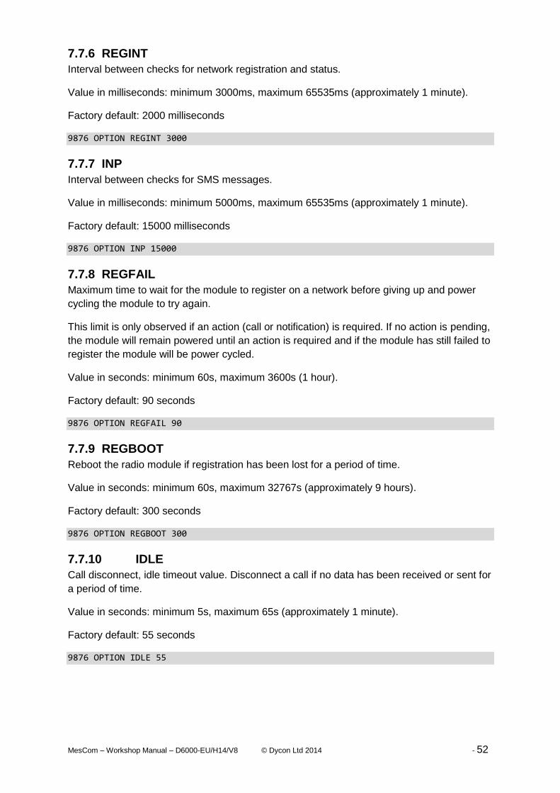
MesCom – Workshop Manual – D6000-EU/H14/V8 © Dycon Ltd 2014 - 52
7.7.6 REGINT
Interval between checks for network registration and status.
Value in milliseconds: minimum 3000ms, maximum 65535ms (approximately 1 minute).
Factory default: 2000 milliseconds
9876 OPTION REGINT 3000
7.7.7 INP
Interval between checks for SMS messages.
Value in milliseconds: minimum 5000ms, maximum 65535ms (approximately 1 minute).
Factory default: 15000 milliseconds
9876 OPTION INP 15000
7.7.8 REGFAIL
Maximum time to wait for the module to register on a network before giving up and power
cycling the module to try again.
This limit is only observed if an action (call or notification) is required. If no action is pending,
the module will remain powered until an action is required and if the module has still failed to
register the module will be power cycled.
Value in seconds: minimum 60s, maximum 3600s (1 hour).
Factory default: 90 seconds
9876 OPTION REGFAIL 90
7.7.9 REGBOOT
Reboot the radio module if registration has been lost for a period of time.
Value in seconds: minimum 60s, maximum 32767s (approximately 9 hours).
Factory default: 300 seconds
9876 OPTION REGBOOT 300
7.7.10 IDLE
Call disconnect, idle timeout value. Disconnect a call if no data has been received or sent for
a period of time.
Value in seconds: minimum 5s, maximum 65s (approximately 1 minute).
Factory default: 55 seconds
9876 OPTION IDLE 55

MesCom – Workshop Manual – D6000-EU/H14/V8 © Dycon Ltd 2014 - 53
7.7.11 MAXLEN
Maximum total call length. Disconnect a call if it has continued for a period of time.
Value in seconds: minimum 0s, maximum 32767s (approximately 9 hours).
Factory default: 600 seconds
9876 OPTION MAXLEN 600
7.7.12 SAMPLE
Input sampling period.
Value in milliseconds: minimum 20ms, maximum 65535ms (approximately 1 minute).
Factory default: 20 milliseconds
9876 OPTION SAMPLE 20
7.7.13 PULLUP
Input resistor. Inputs can be pulled up or pulled down. It is not possible to disable the input
resistor.
Options
Yes - Resistor pullup enabled (factory default).
No - Resistor pull down enabled.
9876 OPTION PULLUP NO
7.7.14 LOGINT
Routine logging interval. This can be used to trigger a periodic reading of an input (eg.
temperature) to allow users to see a trend in that signal. Inputs and outputs can be individual
configured to be included in the routine logging - see POINT LOG parameter.
Please note this can be used to generate a large number of events and should be used with
caution. We recommend SMS only be used with a long interval.
Value in minutes: minimum 1min, maximum 32767min (approximately 22 days).
Factory default: 60 minutes
9876 OPTION LOGINT 60
Also see POINT LOG and NLOG parameters for logging behaviour.
7.7.15 HEALTH
Routine call interval. This can be used to trigger a periodic call to a host, which could be
used to confirm the device is still operational.
Value in minutes: minimum 5min, maximum 32767min (approximately 22 days).
Factory default: 1440 minutes
9876 OPTION HEALTH 10080

MesCom – Workshop Manual – D6000-EU/H14/V8 © Dycon Ltd 2014 - 54
7.7.16 SYNC
Time of day to synchronise activities. Allow routine logs and calls to be synchronised daily to
assist analysis or logged data, Ie. A log will be performed at this time.
Value in minutes past midnight: minimum 0, maximum 1440
zero = midnight, 1440 and above disable the synchronisation.
Factory default: 600 minutes past midnight (10:00am)
9876 OPTION SYNC 600
7.7.17 CKINT
How often to update the clock. The MesCom has a RTC but this can be periodically
synchronised with an external clock.
Value in minutes: minimum 0min (disabled), maximum 32767min (approximately 22 days).
Factory default: 60 minutes
9876 OPTION LOGINT 60
Also see CKSRC and TIME parameters for more control of MesCom clock.
7.7.18 CKSRC
Source for clock to synchronise with.
Options
0 – Manual update only, disable automatic synchronisation of clock.
1 – Use any available clock source (see below) (factory default).
2 – GSM clock directly from network or from received SMS header.
3 – Will be provided by or fetched from host on next connection.
9876 OPTION CKSRC 1
Also see CKINT and TIME parameters for more control of MesCom clock.
7.7.19 BAUD
Terminal interface.
Permitted values are; 300, 600, 1200, 4800, 9600, 19200bps.
Any other value will cause the MesCom to default to 9600bps.
Factory default: 19200bps
9876 OPTION BAUD 9600
7.7.20 XOFF
Maximum period to be in software flow control hold state before resuming (XON character
assumed missing).
Value in milliseconds: minimum 1000ms, maximum 32767ms (approximately 0.5 minute).
Setting to a value of 0 will disable automatic resume (not recommended).
Factory default: 10000 milliseconds
9876 OPTION REGINT 10000

MesCom – Workshop Manual – D6000-EU/H14/V8 © Dycon Ltd 2014 - 55
7.7.21 HOLDOFF
Pause between event happening and notification being send to allow for additional events to
happen, therefore allowing for a more complete picture of the event to be sent and hopefully
reducing the number of notifications caused by transient events.
Value in seconds: minimum 0s, maximum 32767s (approximately 9 hours).
Factory default: 5 seconds
9876 OPTION HOLDOFF 10
7.7.22 SUPPRESS
Input that triggers enter/exit suppress “Engineer on site” mode.
See section 4.3 for more detail on “Engineer on site”.
255 to disable “Engineer on site” mode.
Factory default: 0 (test button)
9876 OPTION SUPPRESS 1
Also see SUPPTIME parameter.
In addition to entering suppress mode, an admin user can enable/disable this mode with the
START/STOP keywords.
9876 OPTION SUPPRESS START
The suppress input will still be functional and SUPPTIME will still be used to disable
suppress mode after the time has expired.
7.7.23 SUPPTIME
Maximum time before exiting suppress “engineer on site” mode.
Value in seconds: minimum 0 (disables timeout), maximum 32767s (approximately 9 hours).
Factory default: 3600 seconds (1 hour)
9876 OPTION SUPPTIME 600
Also see SUPPTIME parameter.

MesCom – Workshop Manual – D6000-EU/H14/V8 © Dycon Ltd 2014 - 56
7.7.24 RINGMODE
RING actions configuration.
The value should be the sum of the options that should be active.
Options
1 – Ignore all incoming calls and connection attempts.
2 – Reserved.
4 – Allow output changing by calling MesCom from SMS users’ phone number.
8 – Respond to a call from SMS users’ phone number with SMS of current input status.
16 – Hang up on incoming calls and call the programmed host.
32 – Allow incoming calls from unknown phone numbers (you are advised to set 16 also).
64 – Send status report to all users if button is held for 5 seconds.
128 – Create status report as part of routine log interval, see OPTION LOGINT.
Factory default: 28 (allow output, status and ringback)
9876 OPTION RINGMODE 16
7.7.25 CMDMODE
Command processing options.
WARNING - should you disable all command methods, the MesCom is only recoverable with
a factory reset.
The value should be the sum of the options that should be active.
Options
1 – Disable commands via SMS.
2 – Reserved
4 – Do not ask for settings from data concentration servers.
8 – Disable commands from terminal.
16 – Disable commands from servers (this will disable FETCH command).
32 – Do not send a response to commands.
64 – Allow SMS from unknown numbers.
128 – Make START command administrator use only.
Factory default: 6 (allow SMS, terminal, Host)
9876 OPTION CMDMODE 0
7.7.26 MSGTIME
Packet wait time - maximum time to wait for response to a message packet in a call. The call
will be aborted if this time is reached.
Value in seconds: minimum 0s, maximum 65535s (approximately 1 month).
Value of zero disables the timeout.
Factory default: 30 seconds
9876 OPTION CMDEXP 60

MesCom – Workshop Manual – D6000-EU/H14/V8 © Dycon Ltd 2014 - 57
7.7.27 SYSACT
What action to take for system event level.
The value should be the sum of the options that should be active.
Options
1 – Send high level system events to SMS users (factory default).
2 – Reserved.
4 – Send high level system events to data concentration servers.
8 – High level system events trigger call to host.
16 – Allow bug reports to be sent to the manufacturer.
32 – Reserved.
64 – Reserved.
128 – Reserved.
9876 OPTION SYSACT 9
Also see SYSTEM and FACTORY parameter.
9876 OPTION ERRDELAY 1000
7.7.28 NUMRETRY
Should a call fail, the MesCom will attempt to retry the call. This sets the maximum number
of retry quick attempts before waiting for an extending period.
Minimum 0, maximum 255.
Factory default: 3 retries
9876 OPTION NUMRETRY 10
7.7.29 RETRY
Gap between quick retries.
Value in seconds: minimum 0s, maximum 32767s (approximately 9 hours).
Factory default: 120 seconds (2 minutes)
9876 OPTION RETRY 120
7.7.30 EXTRETRY
Big gap between retries batches.
Value in minutes: minimum 0min, maximum 32767min (approximately 22 days).
Factory default: 120 minutes (2 hours)
9876 OPTION EXTRETRY 60

MesCom – Workshop Manual – D6000-EU/H14/V8 © Dycon Ltd 2014 - 58
7.7.31 MAXSKIPS
The maximum number of consecutive events to skip. To reduce the number of SMS sent by
the MesCom if consecutive stored events are for the same point, the earlier message will be
skipped.
Minimum 0, maximum 255.
Factory default: 8 events
9876 OPTION MAXSKIPS 8
7.7.32 MAXUPLOAD
Maximum number of events to upload in one batch. If multiple events are to be uploaded,
the time taken to send them to a server could hold up sending and receiving of SMS by the
MesCom. If the responsiveness of the MesCom to SMS is important so data connections are
unreliable, set this to a low number - this will cause the MesCom to end the connection,
check SMS and reconnected to send more event logs.
Minimum 0, maximum 255.
Factory default: 50 events
9876 OPTION MAXUPLOAD 50
7.7.33 TIME
Allow the time to be manually set. Depending on clock settings this time could be over
written when the clock is synchronised.
Time and date in the 24-hour format: dd/mm/yy,HH:MM:SS±zzzz
Where
dd – day of the month.
mm – month of the year (number eg December = 12).
yy – last 2 digits of year (eg.2021=21).
HH – hour of the day in 24 hour format (eg 1pm = 13, midnight = 00).
MM – minutes past the hour.
SS – seconds past the minute.
±zzzz – time zone in the 4 digit 24 hour format (eg 1 hour ahead of GMT is +0100).
Please note: time zone reference is always GMT (also referred to as UTC) and never
daylight saving time (eg BST).
9876 OPTION TIME 23-01-14,13:45:45+0100
Also see CKSRC and CKINT parameters for more control of MesCom clock.
7.7.34 PIN
Set the PIN for the SIM card – does not change the PIN on the SIM card itself and is only
used if the SIM card requires a PIN. If the stored PIN fails to unlock the SIM, the stored PIN
will be deleted. (Typically this command will only be used from terminal interface.).
Factory default: 0000
9876 OPTION PIN 12345678

MesCom – Workshop Manual – D6000-EU/H14/V8 © Dycon Ltd 2014 - 59
7.7.35 ICCID
This is a read only command for use with the VIEW OPTION command.
Display the current SIM card ICCID number.
9876 VIEW OPTION ICCID
7.7.36 IMEI
This is a read only command for use with the VIEW OPTION command.
Display the radio module IMEI number.
9876 VIEW OPTION IMEI
7.7.37 APN
Provide APN settings. The MesCom can support 2 APNs if both are set; the MesCom is
unable to attach to the primary APN, the secondary APN will be used. This command can be
used to set both the primary and secondary APNs. The first use will set the primary, the
second use will set the secondary all subsequent uses of the command will set the primary
until the REMOVE keyword is used and the secondary will be removed, and a subsequent
command will then set the secondary. The primary APN can’t be removed, only over written.
9876 OPTION APN <Access_Point_Name> <username> <password>
Eg.
9876 OPTION APN internet web web
See section 16 for common UK APN settings. Username and password can be left blank but
no more OPTION parameters should follow in the same SMS.
To remove the secondary APN and allow a new secondary APN to be set.
9876 OPTION APN REMOVE
Follow this command with the set command above to set the secondary APN.
7.7.38 ACCOUNT
Set the default access levels and incoming authentication for unknown users and terminal
access. See section 5 for more detail of user settings.
Factory default: na <imei> 1 2 0 na
Where <imei> is the last 4 digits of the IMEI number.
9876 OPTION ACCOUNT <address> <password> <access> <format> <transport> <username>
eg
9876 OPTION ACCOUNT ignored password 2 2 4 username
7.7.39 FACTORY
Set the address of the MesCom configuration server. See section 5 for more detail of user
settings.
Factory default: Dycon configuration manager (http://www.dyconconfig.com).
9876 OPTION FACTORY ftp.mydomain.com:21 password 4 0 7 username
Runtime error reports can also be sent to this address - see SYSACT parameters.

MesCom – Workshop Manual – D6000-EU/H14/V8 © Dycon Ltd 2014 - 60
7.7.40 DEBUG
Terminal debug output level - this can be set remotely but only affects the real-time
debugging output to the wired terminal interface.
Minimum 0, maximum 255 (the higher the number, the more debug messages are produced)
the value of zero disable debug output.
Factory default: 221 (all but the every verbose debug messages)
9876 OPTION DEBUG 60
7.7.41 SYSTEM
System event number that needs action, any general system event with a lower number than
this will trigger the actions as set by

MesCom – Workshop Manual – D6000-EU/H14/V8 © Dycon Ltd 2014 - 61
SYSACT. See section 19.1 for a list of general system events.
Minimum 0, maximum 255.
The value of zero will mean no system events actioned.
Factory default: 2 (suppress mode and system started)
9876 OPTION SYSTEM 60
Also see SYSACT parameter

MesCom – Workshop Manual – D6000-EU/H14/V8 © Dycon Ltd 2014 - 62
8 Factory Defaults To reset the setting to factory defaults, hold down the test button while powering up the device. When the yellow LED starts to flash quickly, release
and press the test button again. See section 4.2.1 for more detail.
For general configuration defaults, see individual parameter details in section 7.7.
8.1 Default Password The default MesCom password is the last 4 digits of the units IMEI number which is printed on the radio module label inside the MesCom. This
password will only work if there are no primary users already subscribed to the MesCom.
8.2 Default System Point Configuration Factory defaults system points. These can be confirmed with the VIEW POINT command.
Po
int
De
finitio
n
Type
Na
me
Dis
pla
y
Min
imu
m
Leve
l 1
Thre
sho
ld
1
Leve
l 2
Thre
sho
ld
2
Leve
l 3
Thre
sho
ld
3
Leve
l 4
Thre
sho
ld
4
Leve
l 5
Dis
pla
y
Ma
xim
um
Hyste
resis
De
bo
un
ce /
Ave
rag
e
1 Signal Strength Analogue RSSI 0 Bad 4 Poor 8 OK 11 Good 18 Great 100 0 0
2 Test Button Digital Button 0.0V Clear 0.5V Press 3V na 3V na 3V na 3.0V 21.5V 3
3 Supply Voltage Analogue Power 0V Off 0.5V UnderV 6.0V On 30V OverV 30.2V vHigh 30.3V 0.5V 50
4 Battery Voltage Analogue Battery 0V Fail 3.5V Low 3.6V OK 3.7V Good 4.24V High 6V 0.05V 200
5 Internal Temp. Analogue Temperature -25°C vLow 5°C Cold 14°C Norm 28°C Hot 41°C vHigh 125°C 0.5°C 200
Factory default action flags for system points.
Point Point Name Enabled Count Alarm Logs SMS Unsol Call
1 RSSI Yes Rising No No No No No
2 Button Yes Rising Press No Yes No Yes
3 Power Yes Rising Yes No Yes No No
4 Battery Yes Rising No No Yes No No
5 Temperature Yes Rising No No Yes No No

MesCom – Workshop Manual – D6000-EU/H14/V8 © Dycon Ltd 2014 - 63
8.3 Default User Input Output Point Configuration Factory defaults user points. These can be confirmed with eth VIEW POINT command.
Po
int
De
finitio
n
Type
Na
me
Dis
pla
y
Min
imu
m
Leve
l 1
Thre
sho
ld 1
Leve
l 2
Thre
sho
ld 2
Leve
l 3
Thre
sho
ld 3
Level 4
Thre
sho
ld 4
Leve
l 5
Dis
pla
y
Ma
xim
um
Hyste
resis
De
bo
un
ce /
Ave
rag
e
6 Input 1 Digital Input1 0.0V Alarm 1.0V Restore 3V na 3V na 3V na 3.0V 0.0V 10
7 Input 2 Digital Input2 0.0V Alarm 1.0V Restore 3V na 3V na 3V na 3.0V 0.0V 10
8 Input 3 Digital Input3 0.0V Alarm 1.0V Restore 3V na 3V na 3V na 3.0V 0.0V 10
9 Input 4 Digital Input4 0.0V Alarm 1.0V Restore 3V na 3V na 3V na 3.0V 0.0V 10
10 Output 1 Digital Output1 0.0V Off 3.0V On 3V na 3V na 3V na 3.0V 0.0V 0
11 Output 2 Digital Output2 0.0V Off 3.0V On 3V na 3V na 3V na 3.0V 0.0V 0
All user points have the same factory default action flags.
Point Name Enabled Count Alarm Logs SMS Unsol Call
All User points Yes Rising Yes No Yes No No
Defaults loaded when using the POINT TYPE parameter to set the point’s current mode of operation, parameter not listed below remain unchanged.
Type
TY
PE
Nu
mb
er
Dis
pla
y
Min
imu
m
Leve
l 1
Thre
sho
ld 1
Leve
l 2
Thre
sho
ld 2
Leve
l 3
Thre
sho
ld 3
Leve
l 4
Thre
sho
ld 4
Leve
l 5
Dis
pla
y
Ma
xim
um
Hyste
resis
De
bo
un
ce /
Ave
rag
e
Co
un
t
Digital 0 0.0V Alarm 1.0V Normal 3.0V 0.5V 10 Rising
Analogue 3 0.0V vLow 0.5V Low 1.0V Normal 2.0V High 2.5V vHigh 3.0V 0.05V 10 Rising
Timer Counter 1 0 Off 1.0V On #32767 threshold #60000 overflow 1000 0.5V 10 Rising
Pulse Counter 2 0 Off 1.0V On #32767 threshold #50000 overflow 500 0.5V 10 Rising
Output 5 0.0V Off 3.0V On 3.0V 0.0V 0 Rising

MesCom – Workshop Manual – D6000-EU/H14/V8 © Dycon Ltd 2014 - 64
9 Using a Pre-Pay SIM Card The current version has no special feature for pre-pay SIM cards - it is up to the user to
ensure the account is kept in credit and that the SIM is used frequently enough to keep the
account active with the service provider.
Most service providers allow the account to be registered online and the account balance to
be checked from a webpage. Topping up can be performed by phone, online, in most shops
and at most ATMs.
The MesCom can be configured to send a routine text message to ensure the SIM is kept
active.
The example below will send a text message with the board temperature every 7days at
10am
9876 OPTION LOGINT 10800 SYNC 600
9876 POINT Temperature LOG yes
10 Using a Roaming SIM Card (TIME not set) The MesCom will work with roaming SIM cards. When using a roaming SIM, the radio
module is unable to get the time in a suitable format so the MesCom is unable to determine
the current time from the GSM network The MesCom will attempt to get the current time
from other sources. If this fails the default power up date is 1st January 2000 - the user can
change this with the OPTION TIME command.
Example:
9876 OPTION TIME 25/07/13,17:52:12+0100
11 Using Web Based Data Concentration Services eg Xively The MesCom has limited support for services such as Xively (aka Cosm or Pachube),
Nimbits etc. Please contact Dycon for more details.
12 FTP Upload The MesCom can use FTP in 2 ways to allow you to see the status of your MesCom via a
remote server. Please contact Dycon for more details.
12.1 Remote Event log The MesCom can be configured to create a list, on a remote FTP server, of all events that
occur in the MesCom. The remote server could be configured to allow this file to be viewed
from a web page or imported into spread-sheet program (eg. Excel).
12.2 Remote status page The MesCom can be configured to create a simple status file on a remote FTP server in
plain text or HTML format. The remote server would have to be configured to allow this file to
be accessed from a web browser on another computer.

MesCom – Workshop Manual – D6000-EU/H14/V8 © Dycon Ltd 2014 - 65
13 Web Configuration Service Please note the availability of the MesCom Configuration manager service is not
guaranteed.
13.1 Using the Configuration Manager To configure your MesCom using this service you will first need to set correct APN in your
MesCom. See section 16 for list or common APN settings.
Example:
9876 OPTION APN internet web web
Alternatively you can manually configure any/all parameters on a MesCom by SMS (see
section 5 for more details).
This is a multi-step process; all steps must be complete successfully to re-configure your
MesCom.
You will need: Your phone number, the MesCom IMEI number, printed on the metal can
inside the MesCom. And the phone number of the MesCom (for you to send the FETCH
command to via SMS).
Please Note: the configuration manager is to simplify the configuration of a MesCom - it
DOES NOT display current status of your MesCom or allow you to control the outputs.
13.1.1 Step 1: Setup the MesCom
See section 3 for details on connected and power up the MesCom.
13.1.2 Step 2: Enable the MesCom
To configure your MesCom using this configuration manager service, you will first need to
set the APN in your MesCom. See section 16 for a list of common network APN settings.
Example:
9876 OPTION APN internet web web
13.1.3 Step 3: Log in / create web manager account
Using the web browser on your smartphone, computer or any other internet connected
device, visit http://www.dyconconfig.com/ then log in or follow the on screen instructions to
create an account. You will be asked for your phone number this is so the MesCom knows
the configuration has come from you when you send the FETCH command.
13.1.4 Step 4: Create configuration
Navigate to the type of configuration you wish to perform and follow the on-screen
instructions. Fields marked with a red star * must be completed as these are required by the
MesCom to process the configuration. All other fields are optional and only the fields you
complete will be changed in the MesCom.
Please note: due to the design of the MesCom system only the previously entered
configuration can be viewed. If you have changed the configuration by other means these
changes will not be shown and will be overwritten next time you FETCH.
The most common changes are included on the quick configuration form, more detailed
settings can be access in the advanced section but should be used with care.
MesCom – Workshop Manual – D6000-EU/H14/V8 © Dycon Ltd 2014 - 66
13.1.5 Step 5: Submit configuration to the server
Once you have filled in all the sections you wish to make changes to, the form must be
submitted to the server so the configuration can be prepared for the MesCom. At this point
you will be prompted to send the FETCH command and providing you have the option
selected in your account settings you will be send a copy of the configuration via email as a
record of the changes.
After submitting new users always send the FETCH command as user changes are only
included in the configuration for the MesCom once to avoid overwriting users passwords.
13.1.6 Step 6: Instruct MesCom to get configuration
With the configuration has been successfully submitted to the server, the MesCom can be
instructed to retrieve the configuration from the server: to do this you need to send the
FETCH command via SMS from your mobile phone.
9876 FETCH
13.1.7 Step 7: Wait for confirmation
The MesCom will not respond immediately to the FETCH command as it must connect to the
server and update its configuration before it can reply with a success or failure message.
13.2 Re-configuring the MesCom The MesCom can be re-configured at any time using the above method. Should you wish to
re-assert the last configuration sent from the configuration manager you can either:
1. Send the FETCH command to the MesCom and it will download the last
configuration setting.
2. Power up the MesCom with the test button held for 10 seconds (or until the LEDs
stop flashing together) - see section 4.2.1 for more detail.
13.3 Security The configuration manager can only have one instance of a MesCom in its system. Should
you as the owner wish to allow the MesCom to be configured by another user of the system,
you will need to share it with their username (email address).
The MesCom will only contact the configuration manager when it receives a FETCH
command from a valid administer to its system, or when someone physically uses the
power-up method detailed in section 4.2.1. The MesCom will only process the configuration
from the server if the configuration is stamped with a valid administrator’s phone number.

MesCom – Workshop Manual – D6000-EU/H14/V8 © Dycon Ltd 2014 - 67
14 Appendix 1 - Specification Model D6000
Dimension (h x w x d) 92 x 60 x 20mm
Weight 77g including battery + 10g antenna
Temperature -20°C to +60°C transit / -4°C to +40°C operating
Humidity 0 – 80% non-condensing
Warranty 2 years
Radio Path GPRS and GSM
Battery 640mAh 3.7v lithium polymer
Charger Built-in
Power Consumption 9–30Vdc 500mA max (2A if used without a battery – not advised)
Typically 50mA at 12v
Standards
Connections Power: 5mm screw terminals Inputs/Outputs: 5mm screw terminals Battery: JST ZHR Antenna: SMA SIM: Mini
International Radio Approval
The D6000 MesCom incorporates an independently tested and approved GSM/GPRS radio module that meets the requirements of European radio communication standards.
Approval Authority: CE0889

MesCom – Workshop Manual – D6000-EU/H14/V8 © Dycon Ltd 2014 - 68
15 Appendix 2 - Glossary of Terms
Bus master The panel is the bus master for the RS485 bus
RS485 In this document this refers to the 2 wire signalling protocol used for the Galaxy system bus
RS232 PC standard serial interface, legacy serial interface standard commonly used in
communication devices
IP Internet Protocol
TCP Transmission Control Protocol (correctly written TCP/IP as TCP sits on top of IP)
UDP User Datagram Protocol (correctly written UDP/IP as UDP sits on top of IP)
SIM Subscriber Identity Module, small card supplied by network operation that, when connected to a radio module, allows the module to connect to the mobile network
GSM Global System for Mobile communication (2G)
GPRS General Packet Radio Service
EDGE Extra Data-rates for Global Evolution
CSD Circuit Switched Data
ADC Analogue to Digital Convertor
SMA Antenna connector
LED Light Emitting Diode
SSN SIM Serial Number (ICCID)
ICCID Integrated Circuit Card Identifier
IMEI International Mobile Equipment Identity – used as serial number for the MesCom
UART Universal Asynchronous Receiver/ Transmitter
PIN Personal Identification Number, a means to prevent unauthorised use of a SIM card
NVM Non-Volatile Memory
IO Input/output
NEC manufacturer of microcontroller
LVI Low Voltage detection module
TDMA Time Division Multiple Access (technique used for GSM)
APN Access Point Name
SMS Short Message Service, a mobile phone text message
MBUS Meter-BUS, low cost utility meter interface EN 13757
MODBUS MODicon communication BUS, common interface for measurement and control devices
EEPROM Electronically Erasable Programmable Read Only Memory, a type of NVM
FET Field Effect Transistor, an semiconductor switch device
SO Standard Output can be used to refer to an open collector output used on utility meters
ATM Automatic Teller Machine, cashpoint
Optocouple Semiconductor device used to isolate a signal, for either safety or electrical reasons.
Back EMF Reverse voltage (Electro Motive Force) generated when an inductive load is switched off
USSD Unstructured Supplementary Service Data, a protocol used by GSM networks to communicate with the service providers computers.
For additional explanation please refer to the internet

MesCom – Workshop Manual – D6000-EU/H14/V8 © Dycon Ltd 2014 - 69
http://encyclopedia.thefreedictionary.com/
http://www.acronymfinder.com/
16 Appendix 3 UK GPRS Settings This setting are provided for reference only they were correct on 1st July 2013 please check
with your SIM card provided before use.
O2
Access point: mobile.o2.co.uk
Username: mobileweb
Password: password
Vodafone
AP (Contract): internet
AP (PAYG): pp.vodafone.co.uk
AP (1GB pp): pp.internet
AP (3GB pp): ppbundle.internet
Username: web
Password: web
Orange
Access Point: orangeinternet
AP (Old PAYG): payginternet
AP (Inet Any): consumerbroadband
Username: user
Password: pass
T-mobile
Access Point: general.t-mobile.uk
Username : user (alt: wapuser)
Password: wap
3UK – Please note SIMs from this network
are not work compatible with the MesCom.
Access Point: three.co.uk
Username: guest
Password: guest
Tesco-Mobile
Access Point: prepay.tesco-mobile.com
Username : tescowap
Password: password
Virgin Mobile
Access Point: goto.virginmobile.uk
Username: user
Password: (leave blank)
GiffGaff
Access Point: giffgaff.com
Username: giffgaff
Password: password
BT Mobile
Access Point: btmobile.bt.com
Username: bt
Password: bt
Asda Mobile
Access Point: asdamobiles.co.uk
Username: web
Password: web
Your Family Mobile (Ikea)
Access Point: data.uk
Username: user
Password: wap
Talk Mobile
Access Point: talkmobile.co.uk
Username:
Password:

MesCom – Workshop Manual – D6000-EU/H14/V8 © Dycon Ltd 2014 - 70
17 Appendix 4 Network PAYG balance numbers For the MesCom to be able to monitor PAYG credit it must be provided with a suitable USSD
number for balance checks. Not all networks provide a USSD number for credit balance
checking.
Credit monitoring is currently not available in the MesCom2.
Network Credit balance number
O2 *#10#
Vodafone *#1345#
Orange *141*#
T-mobile Not Supported (Text Ba to 150)
3 UK Network not supported by MesCom
Tesco *#10#
GiffGaff *100#
BT Mobile *#10#
Asda *#1345#
TalkMobile *#1345#
Virgin Not Supported (Text balance to 789000)
FamilyMobile Not Supported (Text Ba to 4532)
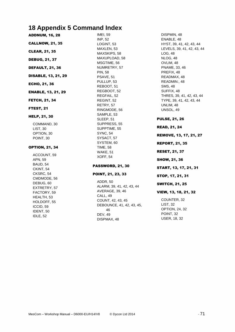
MesCom – Workshop Manual – D6000-EU/H14/V8 © Dycon Ltd 2014 - 71
18 Appendix 5 Command Index ADDNUM, 16, 28
CALLNOW, 21, 35
CLEAR, 21, 35
DEBUG, 21, 37
DEFAULT, 21, 36
DISABLE, 13, 21, 29
ECHO, 21, 36
ENABLE, 13, 21, 29
FETCH, 21, 34
FTEST, 21
HELP, 21, 30
COMMAND, 30
LIST, 30
OPTION, 30
POINT, 30
OPTION, 21, 34
ACCOUNT, 59
APN, 59
BAUD, 54
CKINT, 54
CKSRC, 54
CMDMODE, 56
DEBUG, 60
EXTRETRY, 57
FACTORY, 59
HEALTH, 53
HOLDOFF, 55
ICCID, 59
IDENT, 50
IDLE, 52
IMEI, 59
INP, 52
LOGINT, 53
MAXLEN, 53
MAXSKIPS, 58
MAXUPLOAD, 58
MSGTIME, 56
NUMRETRY, 57
PIN, 58
PSAVE, 51
PULLUP, 53
REBOOT, 51
REGBOOT, 52
REGFAIL, 52
REGINT, 52
RETRY, 57
RINGMODE, 56
SAMPLE, 53
SLEEP, 51
SUPPRESS, 55
SUPPTIME, 55
SYNC, 54
SYSACT, 57
SYSTEM, 60
TIME, 58
WAKE, 51
XOFF, 54
PASSWORD, 21, 30
POINT, 21, 23, 33
ADDR, 50
ALARM, 39, 41, 42, 43, 44
AVERAGE, 39, 46
CALL, 49
COUNT, 42, 43, 45
DEBOUNCE, 41, 42, 43, 45,
46
DEV, 49
DISPMAX, 48
DISPMIN, 48
ENABLE, 48
HYST, 39, 41, 42, 43, 44
LEVELS, 39, 41, 42, 43, 44
LOG, 48
NLOG, 48
OVLIM, 48
PNAME, 33, 46
PREFIX, 48
READMAX, 48
READMIN:, 48
SMS, 48
SUFFIX, 48
THRES, 39, 41, 42, 43, 44
TYPE, 39, 41, 42, 43, 44
UNLIM, 48
UNSOL, 49
PULSE, 21, 26
READ, 21, 24
REMOVE, 13, 17, 21, 27
REPORT, 21, 35
RESET, 21, 37
SHOW, 21, 36
START, 13, 17, 21, 31
STOP, 17, 21, 31
SWITCH, 21, 25
VIEW, 13, 18, 21, 32
COUNTER, 32
LIST, 32
OPTION, 24, 32
POINT, 32
USER, 18, 32

MesCom – Workshop Manual – D6000-EU/H14/V8 © Dycon Ltd 2014 - 72
19 Appendix 6 Event descriptions All MesCom events are stored in the same format the elements of an event log are:
<uint>Sequence Number – sequential numbering of events may be useful to identity
duplicate or missing events.
<uint>Value – Instantaneous value of point or system event number.
<8bit>Point – number of point(255 for system events).
<2bit>Type – type of event (0-System, 1-Alarm, 2-Restore, 3-Rountine).
<3bit>State – current state.
<3bit>Point Type – points currently defined type or system event sub type.
<7bytes>Time – time and date of event.
<8bits>Status Flags – flags to help manage the actions relating to the log.
19.1 Appendix 6.1 System Event Descriptions General Radio Module Runtime Errors
Value PointType = 0 PointType = 2 PointType = 1
0 Suppression mode Failed SMS Watchdog reset
1 System started Failed to disconnect Illegal instruction reset
2 Suppression mode Disabled Module powered on Point error
3 Brown out restart Failed to switch module on Unknown point type
4 NVM ID mismatch Module off unexpectedly Unknown point
5 New firmware detected Module on unexpectedly Res not defined
6 Logs erased Failed to switch module off State machine error
7 Initialisation failed SMS error NVM erase
8 Not registered NVM write
9 Failed to register NVM command
10 SMS received ADC channel error
11 SMS response sent Stack overflow
12 Routine call
13 Carrier lost during call
14 Radio module rebooted
15 Corrupt log found
16 Failed to connect
17 Failed to attached to APN
18 Failed unsol
19 Invalid contact detected
20 Call maximum length reached
21 Message wait time reached
22 Message Corrupt
23 Ring-back requested
24 Incoming call detected
25 Failed email
26 No SMTP server defined
27 Restart requested
253 Log overflow
254 Log buffer overflow
System event PointType = 3 are factory test reports which are not covered in this document.