Embed Size (px)
Citation preview
This document is issued within the frame and for the purpose of the EUXDAT project. This project has received funding from the European
Union’s Horizon2020 Framework Programme under Grant Agreement No. 777549. The opinions expressed and arguments employed herein
do not necessarily reflect the official views of the European Commission.
This document and its content are the property of the EUXDAT Consortium. All rights relevant to this document are determined by the
applicable laws. Access to this document does not grant any right or license on the document or its contents. This document or its contents
are not to be used or treated in any manner inconsistent with the rights or interests of the EUXDAT Consortium or the Partners detriment and
are not to be disclosed externally without prior written consent from the EUXDAT Partners.
Each EUXDAT Partner may use this document in conformity with the EUXDAT Consortium Grant Agreement provisions.
(*) Dissemination level.-PU: Public, fully open, e.g. web; CO: Confidential, restricted under conditions set out in Model Grant Agreement;
CI: Classified, Int = Internal Working Document, information as referred to in Commission Decision 2001/844/EC.
D4.5 Detailed Specification of the
Infrastructure Platform v3
Keywords:
e-Infrastructure, Specification, Architecture, Platform, Design, Cloud, High Performance
Computing, Big Data, Data Analytics, Agriculture
Document Identification
Status Final Due Date 31/12/2019
Version 1.0 Submission Date 13/01/2020
Related WP WP2, WP3, WP5 Document Reference D4.5
Related
Deliverable(s)
D2.4, D3.5, D4.1,
D4.3, D5.5
Dissemination Level (*) PU
Lead Participant USTUTT Lead Author Nico Struckmann
Contributors ATOS ES
ATOS FR
Reviewers Ioannis Navrozidis
(CERTH)
Pavel Hájek (Plan4ALL)
Document name: D4.5 Detailed Specification of the Infrastructure Platform v3 Page: 2 of 52
Reference: D4.5 Dissemination: PU Version: 1.0 Status: Final
Document Information
List of Contributors
Name Partner
Nico Struckmann USTUTT
José Montanana USTUTT
Anne Haugommard ATOS FR
Ricardo Tejada ATOS ES
Fco Javier Nieto ATOS ES
Document History
Version Date Change editors Changes
0.1 28/11/2019 N.Struckmann (USTUTT) Structure drafted, responsibilities assigned.
0.2 02/12/2019 N.Struckmann (USTUTT) Content populated.
0.3 05/12/2019 J.Montanana (USTUTT) DataMover related integrations.
0.4 09/12/2019 A.Haugommard (ATOS FR)
Assigned subsections populated.
0.5 12/12/2019 R.Tejada (ATOS ES) Subsection for pending integrations.
0.6 13/12/2019 N.Struckmann (USTUTT) Missing figures and footnotes, references.
Exec summary, conclusions and References
0.7 16/12/2019 N.Struckmann (USTUTT) Contributions merged, document completed.
0.8 19/12/2019 N.Struckmann (USTUTT) Review comments addressed.
0.9 11/01/2020 Final version ready for quality review
1.0 13/01/2020 FINAL VERSION TO BE SUBMITTED
Quality Control
Role Who (Partner short name) Approval Date
Deliverable leader Dennis Hoppe (USTUTT) 11/01/2020
Technical manager Fabien Castel (ATOS FR) 13/01/2020
Quality manager Susana Palomares (ATOS ES) 13/01/2020
Project Manager F. Javier Nieto (ATOS ES) 13/01/2020
Document name: D4.5 Detailed Specification of the Infrastructure Platform v3 Page: 3 of 52
Reference: D4.5 Dissemination: PU Version: 1.0 Status: Final
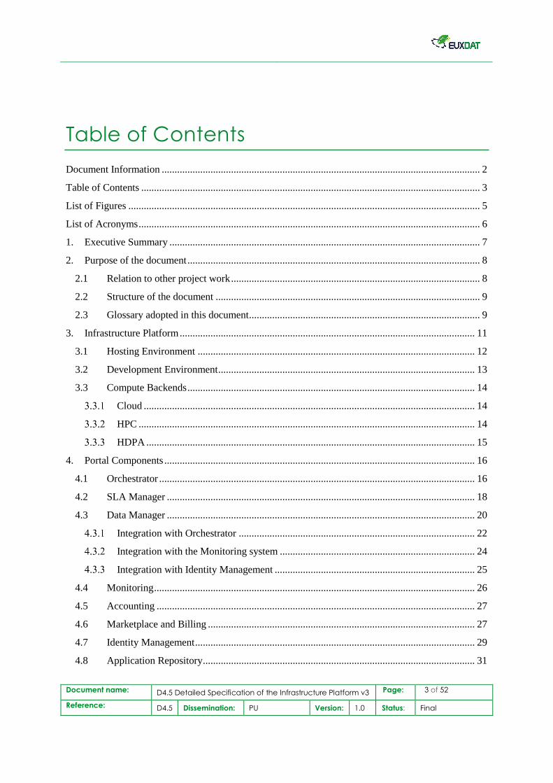
Table of Contents
Document Information ............................................................................................................................ 2
Table of Contents .................................................................................................................................... 3
List of Figures ......................................................................................................................................... 5
List of Acronyms ..................................................................................................................................... 6
1. Executive Summary ......................................................................................................................... 7
2. Purpose of the document .................................................................................................................. 8
2.1 Relation to other project work ................................................................................................. 8
2.2 Structure of the document ....................................................................................................... 9
2.3 Glossary adopted in this document .......................................................................................... 9
3. Infrastructure Platform ................................................................................................................... 11
3.1 Hosting Environment ............................................................................................................ 12
3.2 Development Environment .................................................................................................... 13
3.3 Compute Backends ................................................................................................................ 14
Cloud ................................................................................................................................. 14
HPC ................................................................................................................................... 14
HDPA ................................................................................................................................ 15
4. Portal Components ......................................................................................................................... 16
4.1 Orchestrator ........................................................................................................................... 16
4.2 SLA Manager ........................................................................................................................ 18
4.3 Data Manager ........................................................................................................................ 20
Integration with Orchestrator ............................................................................................ 22
Integration with the Monitoring system ............................................................................ 24
Integration with Identity Management .............................................................................. 25
4.4 Monitoring ............................................................................................................................. 26
4.5 Accounting ............................................................................................................................ 27
4.6 Marketplace and Billing ........................................................................................................ 27
4.7 Identity Management ............................................................................................................. 29
4.8 Application Repository .......................................................................................................... 31
Document name: D4.5 Detailed Specification of the Infrastructure Platform v3 Page: 4 of 52
Reference: D4.5 Dissemination: PU Version: 1.0 Status: Final
4.9 Data Repository ..................................................................................................................... 31
5. Development Infrastructure ........................................................................................................... 32
5.1 Infrastructure Services ........................................................................................................... 33
Source Code Repositories (Git) ......................................................................................... 33
Code Reviews (Gerrit) ....................................................................................................... 35
Continuous Integration (Jenkins) ...................................................................................... 35
Docker Repository (Nexus) ............................................................................................... 37
Kubernetes ......................................................................................................................... 39
5.2 Staging Concept .................................................................................................................... 39
5.3 Disaster Recovery and Backup Concept ............................................................................... 40
5.4 Workflows ............................................................................................................................. 41
Component Development .................................................................................................. 42
Pilot Development ............................................................................................................. 42
6. Deployment Concept ...................................................................................................................... 45
6.1 Component Deployment ........................................................................................................ 45
6.2 Pilot Application Deployment ............................................................................................... 46
7. Conclusions .................................................................................................................................... 48
8. References ...................................................................................................................................... 49
9. Annexes .......................................................................................................................................... 51
9.1 File-Transfers functionalities ................................................................................................. 51
Document name: D4.5 Detailed Specification of the Infrastructure Platform v3 Page: 5 of 52
Reference: D4.5 Dissemination: PU Version: 1.0 Status: Final
List of Figures
Figure 1 EUXDAT Infrastructure Platform ____________________________________________________ 11 Figure 2 Cloud hosting environment (Integration and Production stages) ____________________________ 12 Figure 3 EUXDAT Development Environment __________________________________________________ 13 Figure 4 EUXDAT End-user Platform Components ______________________________________________ 16 Figure 5 Summary of the EUXDAT workflow, in this case the input datasets are in the EUXDAT Cloud _____ 17 Figure 6 Summary of the Orchestrator workflow, in this case the EUXDAT Orchestrator ask a data catalogue
for the metadata of the input datasets in order to locate them ______________________________________ 18 Figure 7. Current SLA Manager Architecture __________________________________________________ 19 Figure 7. Architecture of the file access in the EUXDAT Data Manager ______________________________ 20 Figure 8 Overview of the interactions with the Data Manager _____________________________________ 21 Figure 9 Interactions steps of the Data Manager with the other components for the execution of an app _____ 22 Figure 10 Data Management Interface ________________________________________________________ 24 Figure 11 Data Management pushing data throw the monitoring manager interface ____________________ 24 Figure 12. Integration of Data Manager and the Identity Manager __________________________________ 25 Figure 13 A query to the Rucio database to get info about the registered files _________________________ 26 Figure 14 Kubernetes monitoring with InfluxData suite __________________________________________ 27 Figure 16 Billing system components and their relations __________________________________________ 28 Figure 16 Identity management interactions ___________________________________________________ 30 Figure 18 EUXDAT Development Infrastructure Overview ________________________________________ 32 Figure 18 Gerrit Code Review - Merged Change ________________________________________________ 35 Figure 19 Jenkins CI ______________________________________________________________________ 36 Figure 20 Jenkins Agents __________________________________________________________________ 36 Figure 21 Nexus Docker Repository Configuration ______________________________________________ 38 Figure 22 Nexus Docker Repository Browser ___________________________________________________ 39 Figure 23 Updated Staging Concept __________________________________________________________ 40 Figure 24 Development Workflows ___________________________________________________________ 41 Figure 25 Pilot application development and deployment workflow _________________________________ 43 Figure 26 Sample structure of the GIT repository for Scenario2 application __________________________ 44 Figure 27 : Build and Deployment Pipeline ____________________________________________________ 45 Figure 28 Deployment Concept For Platform Components ________________________________________ 46 Figure 29 Deployment Concept For Pilots _____________________________________________________ 47 Figure 30 Stages of the download of files from a RSE ____________________________________________ 51 Figure 31 Stages of the upload a file into a RSE ________________________________________________ 51 Figure 32 Stages of the replica of files between RSEs ____________________________________________ 52
Document name: D4.5 Detailed Specification of the Infrastructure Platform v3 Page: 6 of 52
Reference: D4.5 Dissemination: PU Version: 1.0 Status: Final
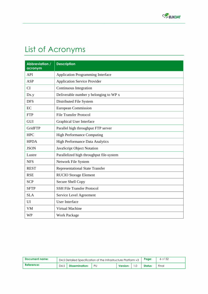
List of Acronyms
Abbreviation /
acronym
Description
API Application Programming Interface
ASP Application Service Provider
CI Continuous Integration
Dx.y Deliverable number y belonging to WP x
DFS Distributed File System
EC European Commission
FTP File Transfer Protocol
GUI Graphical User Interface
GridFTP Parallel high throughput FTP server
HPC High Performance Computing
HPDA High Performance Data Analytics
JSON JavaScript Object Notation
Lustre Parallelized high throughput file-system
NFS Network File System
REST Representational State Transfer
RSE RUCIO Storage Element
SCP Secure Shell Copy
SFTP SSH File Transfer Protocol
SLA Service Level Agreement
UI User Interface
VM Virtual Machine
WP Work Package
Document name: D4.5 Detailed Specification of the Infrastructure Platform v3 Page: 7 of 52
Reference: D4.5 Dissemination: PU Version: 1.0 Status: Final
1. Executive Summary
This document has the purpose to describe the third and final version of the EUXDAT Infrastructure
Platform. It takes into account the previous deliverable “D4.3 Detailed Specification of the
Infrastructure Platform v2” [15] defining the second version of the infrastructure, and accompanying
deliverables D2.6 “EUXDAT e-Infrastructure Definition v3“ and D3.5 “Detailed Specification of the
End Users’ Platform v3” [12].
It describes the final architecture of the infrastructure platform as a whole, rather than a delta only to
the previous versions (D4.1, D4.3).
This document is the fourth one of a series describing the progress over the project’s runtime in depth.
As succeeding documents within WP4, there is D4.6 “Infrastructure Platform v3” in month 30
concluding the achievements and summarizing the state of the infrastructure platform in a final report.
The main content starts with an overview of the EUXDAT Infrastructure Platform, describing the
Portal hosting and computation environments. Following is an in-depth view into the components the
Portal is comprised of. As a next point, the recently carried out work on the infrastructure design, is
described, which was focused on improvements for the collaborative development environment and
workflow to begin with. It comprises all required services and physical resources needed to carry out
continuous integration and quality checks, with the goal to ensure a stable end-user production
platform separated from development environments. Remaining component designs have been
specified, new infrastructure services have been introduced, and the existing staging concept adopted
to issues identified.
As a last point, an overview about the final development and deployment infrastructure platform
design is provided, highlighting the recent changes in the staging concept and automated deployment
mechanisms designed for the different artefact types under development, such as pilots and
components. The target is to ensure a stable production platform alongside with a flexible
collaborative development and testing environment.
The document ends with a conclusion summarizing the main achievements of the reporting period and
discusses remaining work.
Document name: D4.5 Detailed Specification of the Infrastructure Platform v3 Page: 8 of 52
Reference: D4.5 Dissemination: PU Version: 1.0 Status: Final
2. Purpose of the document
This document describes the third and final version of the EUXDAT Infrastructure Platform
specification. The document contains a full specification of the overall infrastructure design
comprising the changes and new features, rather than a delta to the previous deliverable, only, as it is
the case for D4.3 “Detailed Specification of the Infrastructure Platform v2” [15] from month 16.
It provides details for the latest design of the solutions to be implemented, related to the hybrid
orchestration of workloads, or the input/output data management, SLA enforcement, monitoring, and
the accounting component.
This report describes the targeted final architecture of the project’s infrastructure, intended to be
implemented during the last activity period of WP4, which spans until May 2020 and concludes with
D4.6 as final report describing the actual achievements and possibly necessary deviations from the
specification and implementation plans outlined in this document.
2.1 Relation to other project work
This document is follow-up work for D4.3 “Detailed Specification of the Infrastructure Platform
v2”[15]. Besides taking into consideration D2.1 “Description of Proposed Pilots and Requirements”
[1], D2.2 "EUXDAT e-Infrastructure Definition v1" [2], “D2.3 Updated Report on e-Infrastructure
Requirements v1” [3], D2.4 “EUXDAT e-Infrastructure Definition v2” [4], D2.5 “Updated Report on
e-Infrastructure Requirements v2” [5], and D3.3 “Detailed Specification of the End Users’ Platform
v2” [10]. The document focuses on newly identified requirements towards the infrastructure, as well
as addressing problems and challenges of the previous specifications in demand of deviations from
original plans. In general, it takes into account the outcomes of WP2, and supports WP3 on its mission
to build the end-user platform by providing required servers and services for an efficient, stable and
collaborative development environment.
This WP4 deliverable is the fifth of a series over the project runtime. It is preceded by the following
four deliverables:
• D4.1 Detailed Specification of the Infrastructure Platform v1 - Report (M8)
• D4.2 Infrastructure Platform v1 - Demonstrator (M12)
• D4.3 Detailed Specification of the Infrastructure Platform v2 - Report (M16)
• D4.4 Infrastructure Platform v2 - Demonstrator (M23)
And followed by one deliverable at the end of WP4 activity’s period:
• D4.6 Infrastructure Platform v3 - Demonstrator Public (M31)
Document name: D4.5 Detailed Specification of the Infrastructure Platform v3 Page: 9 of 52
Reference: D4.5 Dissemination: PU Version: 1.0 Status: Final
2.2 Structure of the document
This document’s main content is summarized in four main chapters, divided in subsection containing
the important details and technical aspects of the latest changes to the previously written specifications
and implementation plans, rendering it the final version.
Chapter 3 starts with the project’s infrastructure, comprising the hosting environment and compute
backend, and describing changes leading to the targeted final state.
Chapter 4 provides an overview about the various core components under development, and how
these building blocks are linked and interconnected, the whole EUXDAT Portal is comprised of.
Chapter 5 outlines changes and enhancements to the development infrastructure, improvements of the
formerly specified setup, as well as a newly introduced service supporting development and
administration.
Chapter 6 describes the final version of the deployment concept and deployment workflows,
explaining in detail the common aspects and differences of pilot/scenario deployment logic and core
component deployments.
Chapter 7 finishes the document with a conclusion of the work carried out up to date and presented in
this document. It outlines the main achievements alongside the addressed challenges with an outlook
onto the last activity period of WP4.
2.3 Glossary adopted in this document
Continuous Integration. Software engineering practice in which frequent, isolated changes
are immediately compiled, deployed, tested and reported on when they are added to the code
base.
Code Review. Part of the quality assurance takes place before Continuous Integration, and
comprises one or several developers checking changes of the code before being merged into
the code base.
Deployment. Software Deployment is the process of making software available for use.
Stage. A development environment for implementing and testing
installation/configuration/migration scripts and procedures before going into production.
Scheduler. A software/service deciding when a workload is planned to be deployed on which
resources based on rules, policies and SLAs.
Resource Manager. A software/service managing any kind of (consumable) IT resources
such as compute nodes, accelerator cards and GPUs, besides monitoring and accounting.
Container. Standardized, lightweight, standalone, executable package of software that
includes everything needed to run an application: code, runtime, system tools, system libraries
and settings. A virtual application execution environment, packed as portable file.
Kubernetes Pod. Group of Docker containers sharing data and network. Every micro-service,
such as graphical end-user frontends, central platform components, or database in the
EUXDAT Cloud, is packaged into a pod managed by Kubernetes.
Document name: D4.5 Detailed Specification of the Infrastructure Platform v3 Page: 10 of 52
Reference: D4.5 Dissemination: PU Version: 1.0 Status: Final
Kubernetes Service. Kubernetes object linking an address to a port of a pod container. This
address can be exposed to the internet through the integrated reverse proxy of Kubernetes,
called the Ingress.
Jupyter Noteboooks. Interactive development environment accessible from a web browser
running remotely on a server, here isolated into a pod. It allows to create and share documents
containing live code, equations, and execute code.
Jupyter Hub. Proxy server routing users of Notebooks to their own pod after authentication,
or spawning them if they are not already running.
Document name: D4.5 Detailed Specification of the Infrastructure Platform v3 Page: 11 of 52
Reference: D4.5 Dissemination: PU Version: 1.0 Status: Final
3. Infrastructure Platform
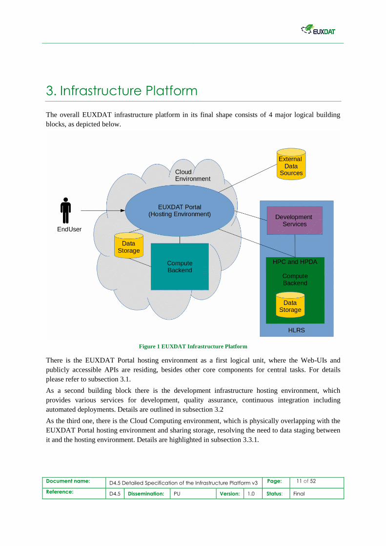
The overall EUXDAT infrastructure platform in its final shape consists of 4 major logical building
blocks, as depicted below.
Figure 1 EUXDAT Infrastructure Platform
There is the EUXDAT Portal hosting environment as a first logical unit, where the Web-UIs and
publicly accessible APIs are residing, besides other core components for central tasks. For details
please refer to subsection 3.1.
As a second building block there is the development infrastructure hosting environment, which
provides various services for development, quality assurance, continuous integration including
automated deployments. Details are outlined in subsection 3.2
As the third one, there is the Cloud Computing environment, which is physically overlapping with the
EUXDAT Portal hosting environment and sharing storage, resolving the need to data staging between
it and the hosting environment. Details are highlighted in subsection 3.3.1.
Document name: D4.5 Detailed Specification of the Infrastructure Platform v3 Page: 12 of 52
Reference: D4.5 Dissemination: PU Version: 1.0 Status: Final
The last logical unit from an abstract view on the overall infrastructure is the HPC/HPDA compute
environment, which is physically in the same location and share a common parallel file-system. For
details concerning both systems please refer to subsection 3.3.2 and subsection 3.3.3.
3.1 Hosting Environment
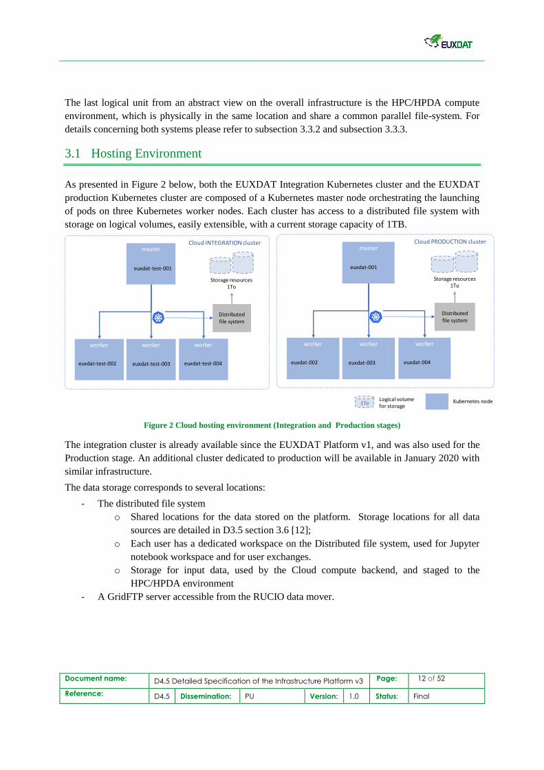
As presented in Figure 2 below, both the EUXDAT Integration Kubernetes cluster and the EUXDAT
production Kubernetes cluster are composed of a Kubernetes master node orchestrating the launching
of pods on three Kubernetes worker nodes. Each cluster has access to a distributed file system with
storage on logical volumes, easily extensible, with a current storage capacity of 1TB.
Figure 2 Cloud hosting environment (Integration and Production stages)
The integration cluster is already available since the EUXDAT Platform v1, and was also used for the
Production stage. An additional cluster dedicated to production will be available in January 2020 with
similar infrastructure.
The data storage corresponds to several locations:
- The distributed file system
o Shared locations for the data stored on the platform. Storage locations for all data
sources are detailed in D3.5 section 3.6 [12];
o Each user has a dedicated workspace on the Distributed file system, used for Jupyter
notebook workspace and for user exchanges.
o Storage for input data, used by the Cloud compute backend, and staged to the
HPC/HPDA environment
- A GridFTP server accessible from the RUCIO data mover.
master
worker
Storage resources 1To
Distributed file system
Cloud PRODUCTION cluster
workerworker
euxdat-001
euxdat-002 euxdat-003 euxdat-004
master
worker
Storage resources 1To
Distributed file system
Cloud INTEGRATION cluster
workerworker
euxdat-test-001
euxdat-test-002 euxdat-test-003 euxdat-test-004
1ToLogical volume for storage
Kubernetes node
Document name: D4.5 Detailed Specification of the Infrastructure Platform v3 Page: 13 of 52
Reference: D4.5 Dissemination: PU Version: 1.0 Status: Final
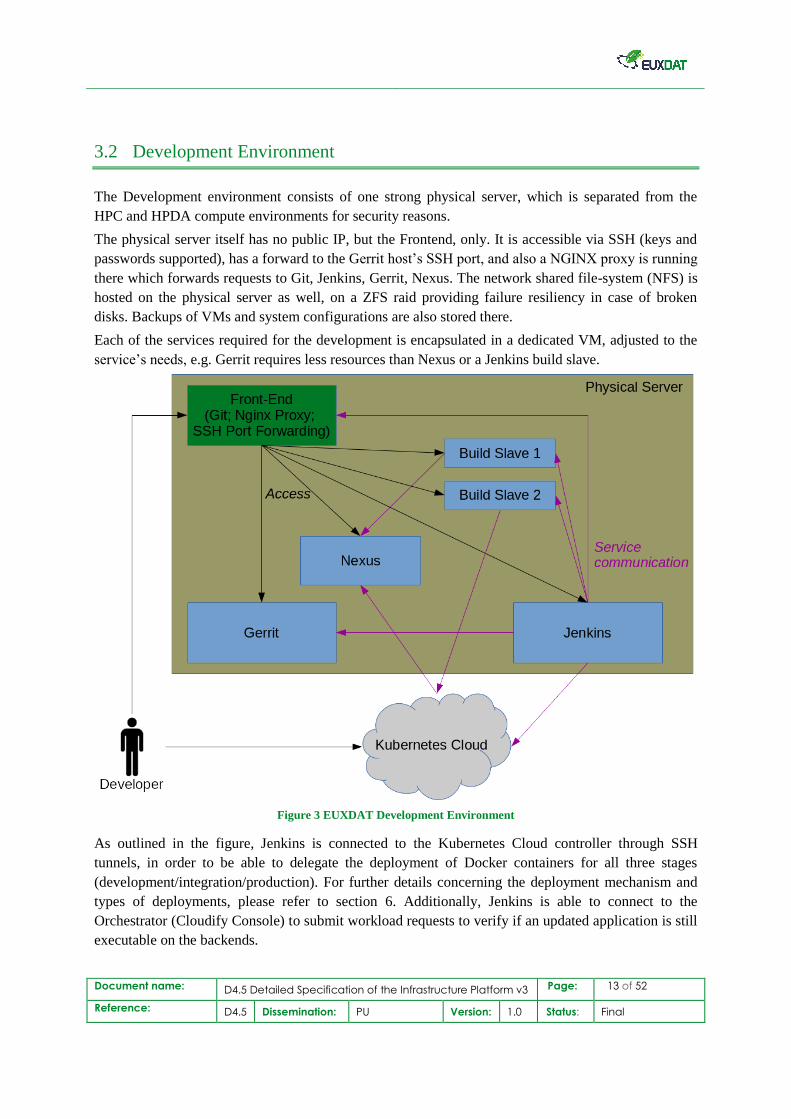
3.2 Development Environment
The Development environment consists of one strong physical server, which is separated from the
HPC and HPDA compute environments for security reasons.
The physical server itself has no public IP, but the Frontend, only. It is accessible via SSH (keys and
passwords supported), has a forward to the Gerrit host’s SSH port, and also a NGINX proxy is running
there which forwards requests to Git, Jenkins, Gerrit, Nexus. The network shared file-system (NFS) is
hosted on the physical server as well, on a ZFS raid providing failure resiliency in case of broken
disks. Backups of VMs and system configurations are also stored there.
Each of the services required for the development is encapsulated in a dedicated VM, adjusted to the
service’s needs, e.g. Gerrit requires less resources than Nexus or a Jenkins build slave.
Figure 3 EUXDAT Development Environment
As outlined in the figure, Jenkins is connected to the Kubernetes Cloud controller through SSH
tunnels, in order to be able to delegate the deployment of Docker containers for all three stages
(development/integration/production). For further details concerning the deployment mechanism and
types of deployments, please refer to section 6. Additionally, Jenkins is able to connect to the
Orchestrator (Cloudify Console) to submit workload requests to verify if an updated application is still
executable on the backends.
Document name: D4.5 Detailed Specification of the Infrastructure Platform v3 Page: 14 of 52
Reference: D4.5 Dissemination: PU Version: 1.0 Status: Final
The other services do not require any connectivity to further environments or services outside of the
development environment, these services just need to be reachable from the outside, via SSH or
HTTPS.
Within the development environment, hosted at HLRS, services are connected to and reachable for
each other. Jenkins gets triggered by Gerrit when new code has been submitted, Jenkins can push build
Docker images to Nexus, Jenkins can delegate the building of binaries and Dockers to the slaves, and
also push updated code onto the git repository residing on the frontend. The git on the Frontend
provides also an HTTPS based interface, besides SSH access.
3.3 Compute Backends
For EUXDAT application providers and their end-users, 3 different types of compute backends are
provided for the workload processing. Each with its unique properties addressing distinct requirements
of applications, such requirements as for example continuously running, or compute/memory/io
intensive resources, or efficient big data processing with deep learning capabilities.
For details for each of the three environments, Cloud, HPC, and HPDA see in the following
subsections where each one is outlined.
Cloud
In the cloud environment, the launching computing jobs corresponds to the start of a new Kubernetes
pod in the cluster, by the Kubernetes master, agnostic of the underlying infrastructure. In both
Integration and Production clusters, pods can be launched on any one of the workers, according to
current resources availability.
Each worker is configured with 8CPU and 16GB RAM in both Integration and Production clusters.
As described in D3.3 [10], the computation capability of the cluster can be easily scalable by the
addition of new worker nodes.
Having the storage resources mounted as logical volumes rather than physical volumes also allows an
easy temporary or permanent increase of the storage resources.
Note: The current deployment choices (1TB storage and 3 x (8CPU, 16GB RAM)) are sufficient for
current usage of the platform and allow to limit infrastructure cost.
HPC
The HPC environment is currently being upgraded, new hardware is installed step by step, while the
old hardware is simultaneously being taken down and replaced. The overall nature of the environment
does not change, only its computation capabilities are increased.
Document name: D4.5 Detailed Specification of the Infrastructure Platform v3 Page: 15 of 52
Reference: D4.5 Dissemination: PU Version: 1.0 Status: Final
There are three frontends with DNS round-robin to balance the load on these entry points and a
GridFTP service which provides access to the user workspaces on the parallel Lustre1 file-system.
There are also pre- and post-processing compute nodes, which can be optionally used in combination
with batch jobs, and are not explicitly highlighted.
As depicted in Figure 1 the HPC, and the HPDA environment described in the next section, share a
common highly parallel Lustre file-system, providing a fast workspace for intermediate data. And
further, there is an NFS storage shared amongst both systems for the user’s homes.
The HPC system itself, in its current as well as new form, are managed by Moab2 as scheduler in
combination with Torque3 as resource manager.
HDPA
The HPDA system is physically located in the same datacentre as the HPC machine and both share the
user homes and workspace file-systems. This setup would even allow the processing of hybrid
workloads that consist of HPC and HPDA requirements.
It has dedicated frontends distinct from the HPC environment. The system management software is
Spark/Mesos, and is suitable for Big Data, Streaming Data, Deep Learning requirements. As of now,
none of the pilots is ported to this system, yet. However, since the integration efforts on the
infrastructure side were low, due to synergies with the EU Project HIDALGO, and an added value in
having this system integrated for the future, as for example Deep Learning processing huge amounts
of satellite images & sensor data for pattern detection may become relevant, it was taken into account.
1 http://lustre.org/ 2 https://www.adaptivecomputing.com/moab-hpc-basic-edition/ 3 https://www.adaptivecomputing.com/products/torque/
Document name: D4.5 Detailed Specification of the Infrastructure Platform v3 Page: 16 of 52
Reference: D4.5 Dissemination: PU Version: 1.0 Status: Final
4. Portal Components
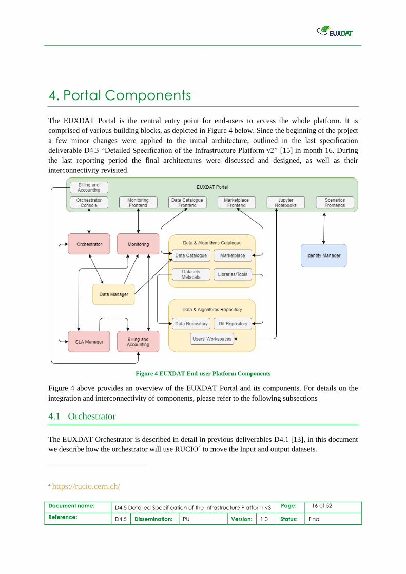
The EUXDAT Portal is the central entry point for end-users to access the whole platform. It is
comprised of various building blocks, as depicted in Figure 4 below. Since the beginning of the project
a few minor changes were applied to the initial architecture, outlined in the last specification
deliverable D4.3 “Detailed Specification of the Infrastructure Platform v2” [15] in month 16. During
the last reporting period the final architectures were discussed and designed, as well as their
interconnectivity revisited.
Figure 4 EUXDAT End-user Platform Components
Figure 4 above provides an overview of the EUXDAT Portal and its components. For details on the
integration and interconnectivity of components, please refer to the following subsections
4.1 Orchestrator
The EUXDAT Orchestrator is described in detail in previous deliverables D4.1 [13], in this document
we describe how the orchestrator will use RUCIO4 to move the Input and output datasets.
4 https://rucio.cern.ch/
Document name: D4.5 Detailed Specification of the Infrastructure Platform v3 Page: 17 of 52
Reference: D4.5 Dissemination: PU Version: 1.0 Status: Final
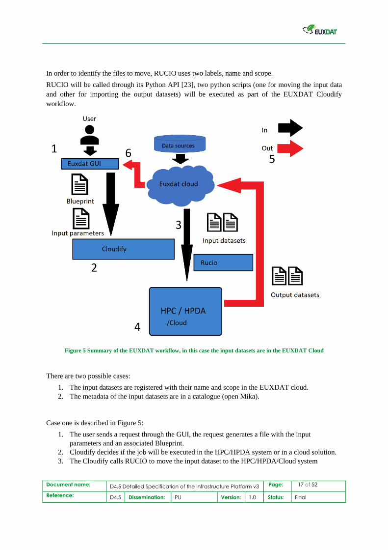
In order to identify the files to move, RUCIO uses two labels, name and scope.
RUCIO will be called through its Python API [23], two python scripts (one for moving the input data
and other for importing the output datasets) will be executed as part of the EUXDAT Cloudify
workflow.
Figure 5 Summary of the EUXDAT workflow, in this case the input datasets are in the EUXDAT Cloud
There are two possible cases:
1. The input datasets are registered with their name and scope in the EUXDAT cloud.
2. The metadata of the input datasets are in a catalogue (open Mika).
Case one is described in Figure 5:
1. The user sends a request through the GUI, the request generates a file with the input
parameters and an associated Blueprint.
2. Cloudify decides if the job will be executed in the HPC/HPDA system or in a cloud solution.
3. The Cloudify calls RUCIO to move the input dataset to the HPC/HPDA/Cloud system
Document name: D4.5 Detailed Specification of the Infrastructure Platform v3 Page: 18 of 52
Reference: D4.5 Dissemination: PU Version: 1.0 Status: Final
4. The job is executed
5. After the job is finished Cloudify calls RUCIO to move the output datasets to the EUXDAT
Cloud, where the user can consult them (6)
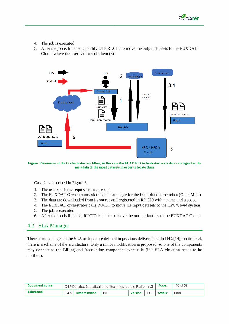
Figure 6 Summary of the Orchestrator workflow, in this case the EUXDAT Orchestrator ask a data catalogue for the
metadata of the input datasets in order to locate them
Case 2 is described in Figure 6:
1. The user sends the request as in case one
2. The EUXDAT Orchestrator ask the data catalogue for the input dataset metadata (Open Mika)
3. The data are downloaded from its source and registered in RUCIO with a name and a scope
4. The EUXDAT orchestrator calls RUCIO to move the input datasets to the HPC/Cloud system
5. The job is executed
6. After the job is finished, RUCIO is called to move the output datasets to the EUXDAT Cloud.
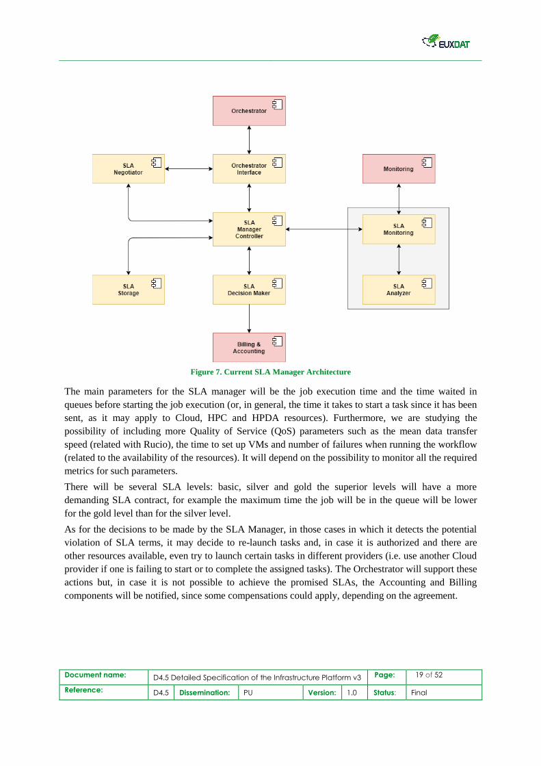
4.2 SLA Manager
There is not changes in the SLA architecture defined in previous deliverables. In D4.2[14], section 4.4,
there is a schema of the architecture. Only a minor modification is proposed, so one of the components
may connect to the Billing and Accounting component eventually (if a SLA violation needs to be
notified).
Document name: D4.5 Detailed Specification of the Infrastructure Platform v3 Page: 19 of 52
Reference: D4.5 Dissemination: PU Version: 1.0 Status: Final
Figure 7. Current SLA Manager Architecture
The main parameters for the SLA manager will be the job execution time and the time waited in
queues before starting the job execution (or, in general, the time it takes to start a task since it has been
sent, as it may apply to Cloud, HPC and HPDA resources). Furthermore, we are studying the
possibility of including more Quality of Service (QoS) parameters such as the mean data transfer
speed (related with Rucio), the time to set up VMs and number of failures when running the workflow
(related to the availability of the resources). It will depend on the possibility to monitor all the required
metrics for such parameters.
There will be several SLA levels: basic, silver and gold the superior levels will have a more
demanding SLA contract, for example the maximum time the job will be in the queue will be lower
for the gold level than for the silver level.
As for the decisions to be made by the SLA Manager, in those cases in which it detects the potential
violation of SLA terms, it may decide to re-launch tasks and, in case it is authorized and there are
other resources available, even try to launch certain tasks in different providers (i.e. use another Cloud
provider if one is failing to start or to complete the assigned tasks). The Orchestrator will support these
actions but, in case it is not possible to achieve the promised SLAs, the Accounting and Billing
components will be notified, since some compensations could apply, depending on the agreement.
Document name: D4.5 Detailed Specification of the Infrastructure Platform v3 Page: 20 of 52
Reference: D4.5 Dissemination: PU Version: 1.0 Status: Final
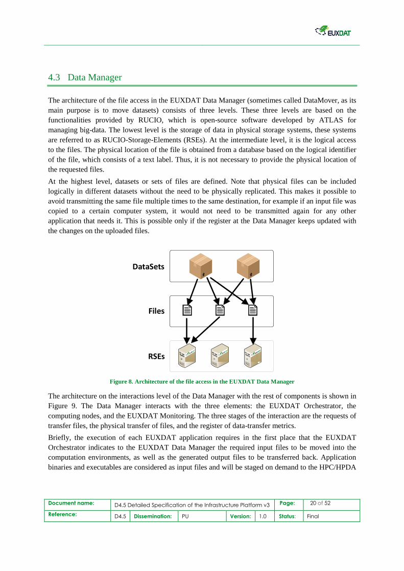
4.3 Data Manager
The architecture of the file access in the EUXDAT Data Manager (sometimes called DataMover, as its
main purpose is to move datasets) consists of three levels. These three levels are based on the
functionalities provided by RUCIO, which is open-source software developed by ATLAS for
managing big-data. The lowest level is the storage of data in physical storage systems, these systems
are referred to as RUCIO-Storage-Elements (RSEs). At the intermediate level, it is the logical access
to the files. The physical location of the file is obtained from a database based on the logical identifier
of the file, which consists of a text label. Thus, it is not necessary to provide the physical location of
the requested files.
At the highest level, datasets or sets of files are defined. Note that physical files can be included
logically in different datasets without the need to be physically replicated. This makes it possible to
avoid transmitting the same file multiple times to the same destination, for example if an input file was
copied to a certain computer system, it would not need to be transmitted again for any other
application that needs it. This is possible only if the register at the Data Manager keeps updated with
the changes on the uploaded files.
DataSets
RSEs
Files
Figure 8. Architecture of the file access in the EUXDAT Data Manager
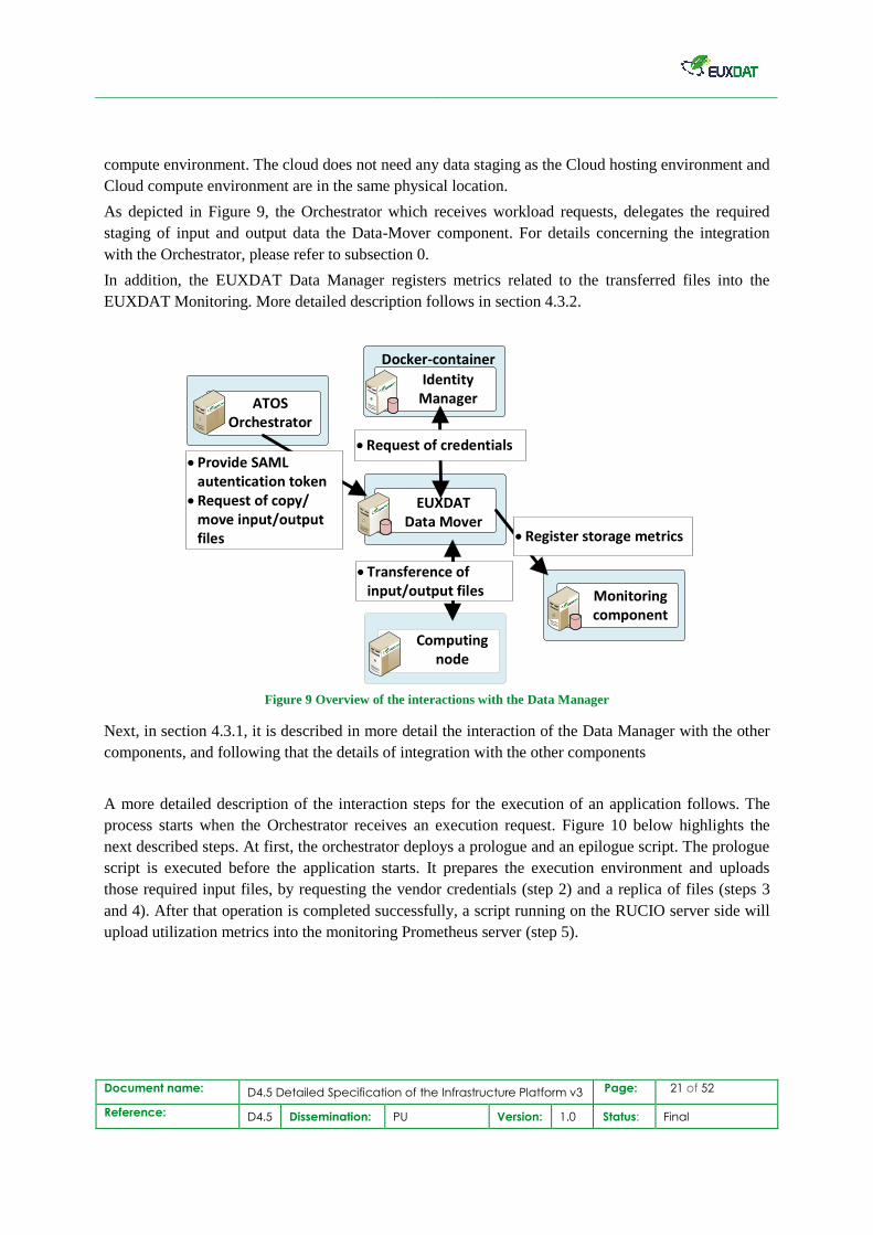
The architecture on the interactions level of the Data Manager with the rest of components is shown in
Figure 9. The Data Manager interacts with the three elements: the EUXDAT Orchestrator, the
computing nodes, and the EUXDAT Monitoring. The three stages of the interaction are the requests of
transfer files, the physical transfer of files, and the register of data-transfer metrics.
Briefly, the execution of each EUXDAT application requires in the first place that the EUXDAT
Orchestrator indicates to the EUXDAT Data Manager the required input files to be moved into the
computation environments, as well as the generated output files to be transferred back. Application
binaries and executables are considered as input files and will be staged on demand to the HPC/HPDA
Document name: D4.5 Detailed Specification of the Infrastructure Platform v3 Page: 21 of 52
Reference: D4.5 Dissemination: PU Version: 1.0 Status: Final
compute environment. The cloud does not need any data staging as the Cloud hosting environment and
Cloud compute environment are in the same physical location.
As depicted in Figure 9, the Orchestrator which receives workload requests, delegates the required
staging of input and output data the Data-Mover component. For details concerning the integration
with the Orchestrator, please refer to subsection 0.
In addition, the EUXDAT Data Manager registers metrics related to the transferred files into the
EUXDAT Monitoring. More detailed description follows in section 4.3.2.
Computing node
Docker-container
IdentityManagerATOS
Orchestrator
Monitoringcomponent
Register storage metrics
EUXDAT Data Mover
Provide SAML autentication token
Request of copy/move input/output files
Request of credentials
Transference of input/output files
Figure 9 Overview of the interactions with the Data Manager
Next, in section 4.3.1, it is described in more detail the interaction of the Data Manager with the other
components, and following that the details of integration with the other components
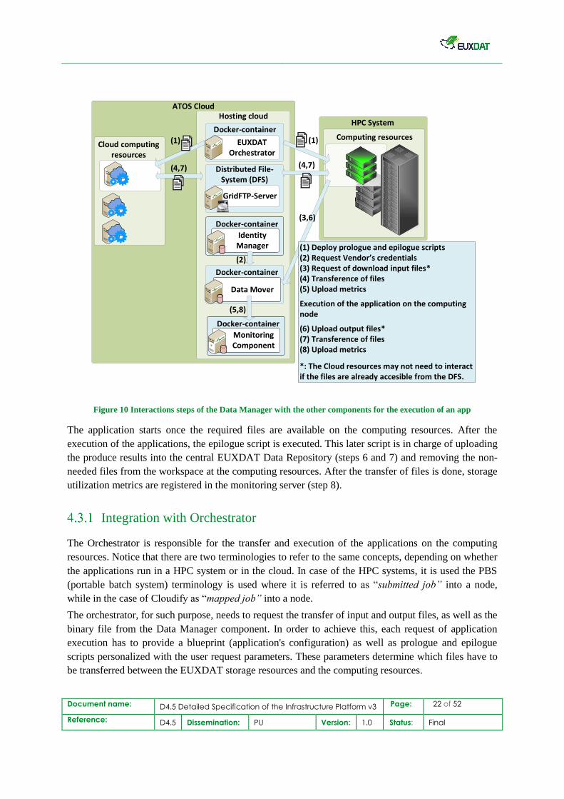
A more detailed description of the interaction steps for the execution of an application follows. The
process starts when the Orchestrator receives an execution request. Figure 10 below highlights the
next described steps. At first, the orchestrator deploys a prologue and an epilogue script. The prologue
script is executed before the application starts. It prepares the execution environment and uploads
those required input files, by requesting the vendor credentials (step 2) and a replica of files (steps 3
and 4). After that operation is completed successfully, a script running on the RUCIO server side will
upload utilization metrics into the monitoring Prometheus server (step 5).
Document name: D4.5 Detailed Specification of the Infrastructure Platform v3 Page: 22 of 52
Reference: D4.5 Dissemination: PU Version: 1.0 Status: Final
ATOS Cloud
Computing resources
Hosting cloud
Cloud computing resources
Docker-container
EUXDAT Orchestrator
Docker-container
Distributed File-System (DFS)
GridFTP-Server
Docker-container
MonitoringComponent
HPC System
Data Mover
(1) Deploy prologue and epilogue scripts(2) Request Vendor s credentials (3) Request of download input files*(4) Transference of files(5) Upload metrics
Execution of the application on the computing node
(6) Upload output files*(7) Transference of files(8) Upload metrics
*: The Cloud resources may not need to interact if the files are already accesible from the DFS.
(1)
(3,6)
(5,8)
(4,7)
(1)
(4,7)
Docker-container
IdentityManager
(2)
Figure 10 Interactions steps of the Data Manager with the other components for the execution of an app
The application starts once the required files are available on the computing resources. After the
execution of the applications, the epilogue script is executed. This later script is in charge of uploading
the produce results into the central EUXDAT Data Repository (steps 6 and 7) and removing the non-
needed files from the workspace at the computing resources. After the transfer of files is done, storage
utilization metrics are registered in the monitoring server (step 8).
Integration with Orchestrator
The Orchestrator is responsible for the transfer and execution of the applications on the computing
resources. Notice that there are two terminologies to refer to the same concepts, depending on whether
the applications run in a HPC system or in the cloud. In case of the HPC systems, it is used the PBS
(portable batch system) terminology is used where it is referred to as “submitted job” into a node,
while in the case of Cloudify as “mapped job” into a node.
The orchestrator, for such purpose, needs to request the transfer of input and output files, as well as the
binary file from the Data Manager component. In order to achieve this, each request of application
execution has to provide a blueprint (application's configuration) as well as prologue and epilogue
scripts personalized with the user request parameters. These parameters determine which files have to
be transferred between the EUXDAT storage resources and the computing resources.
Document name: D4.5 Detailed Specification of the Infrastructure Platform v3 Page: 23 of 52
Reference: D4.5 Dissemination: PU Version: 1.0 Status: Final
Notice that same concepts may be referenced with different names working with cloud computing or
when working with high-performance computing. In particular, PBS terminology, commonly used the
realm of HPC, names the scripts executed before and after the execution of the application or task as
“epilogue” and “prologue”, respectively. Meanwhile, these terms are referenced as “bootstrap” and
“revert” in the Cloudify blueprint.
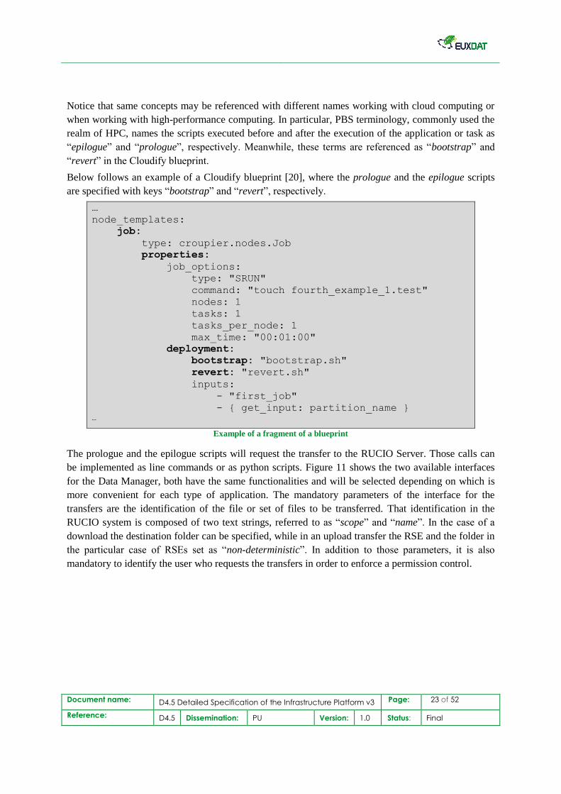
Below follows an example of a Cloudify blueprint [20], where the prologue and the epilogue scripts
are specified with keys “bootstrap” and “revert”, respectively.
…
node_templates:
job:
type: croupier.nodes.Job
properties:
job_options:
type: "SRUN"
command: "touch fourth_example_1.test"
nodes: 1
tasks: 1
tasks_per_node: 1
max_time: "00:01:00"
deployment:
bootstrap: "bootstrap.sh"
revert: "revert.sh"
inputs:
- "first_job"
- { get_input: partition_name } …
Example of a fragment of a blueprint
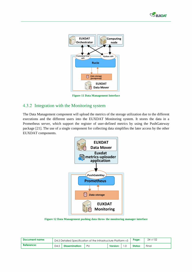
The prologue and the epilogue scripts will request the transfer to the RUCIO Server. Those calls can
be implemented as line commands or as python scripts. Figure 11 shows the two available interfaces
for the Data Manager, both have the same functionalities and will be selected depending on which is
more convenient for each type of application. The mandatory parameters of the interface for the
transfers are the identification of the file or set of files to be transferred. That identification in the
RUCIO system is composed of two text strings, referred to as “scope” and “name”. In the case of a
download the destination folder can be specified, while in an upload transfer the RSE and the folder in
the particular case of RSEs set as “non-deterministic”. In addition to those parameters, it is also
mandatory to identify the user who requests the transfers in order to enforce a permission control.
Document name: D4.5 Detailed Specification of the Infrastructure Platform v3 Page: 24 of 52
Reference: D4.5 Dissemination: PU Version: 1.0 Status: Final
Rucio
EUXDATData Mover
EUXDAT Orchestrator
Computing node
Data storage
[postgresql]
Command line
APIPython API
Figure 11 Data Management Interface
Integration with the Monitoring system
The Data Management component will upload the metrics of the storage utilization due to the different
executions and the different users into the EUXDAT Monitoring system. It stores the data in a
Prometheus server, which support the register of user-defined metrics by using the PushGateway
package [21]. The use of a single component for collecting data simplifies the later access by the other
EUXDAT components.
Data storage
Prometheus
EUXDATData Mover
Euxdatmetrics-uploader
application
PushGateWay
EUXDAT Monitoring
Figure 12 Data Management pushing data throw the monitoring manager interface
Document name: D4.5 Detailed Specification of the Infrastructure Platform v3 Page: 25 of 52
Reference: D4.5 Dissemination: PU Version: 1.0 Status: Final
The upload of metrics will be done after every successful transfer of files and every request for
deletion of files. In this way, the storage metrics will keep an accurate register and not over- or
underestimate the total transfer requests by each user on each RSEs. The Data Manager registers the
total amount of transferred data which it transfers but does not measure the total storage space used
during the execution of the applications, which may change due to the generation of the temporal and
the output files. It is particularly interested in keeping track of the required amount of transferred data,
because it can support the scheduling decision of the application execution.
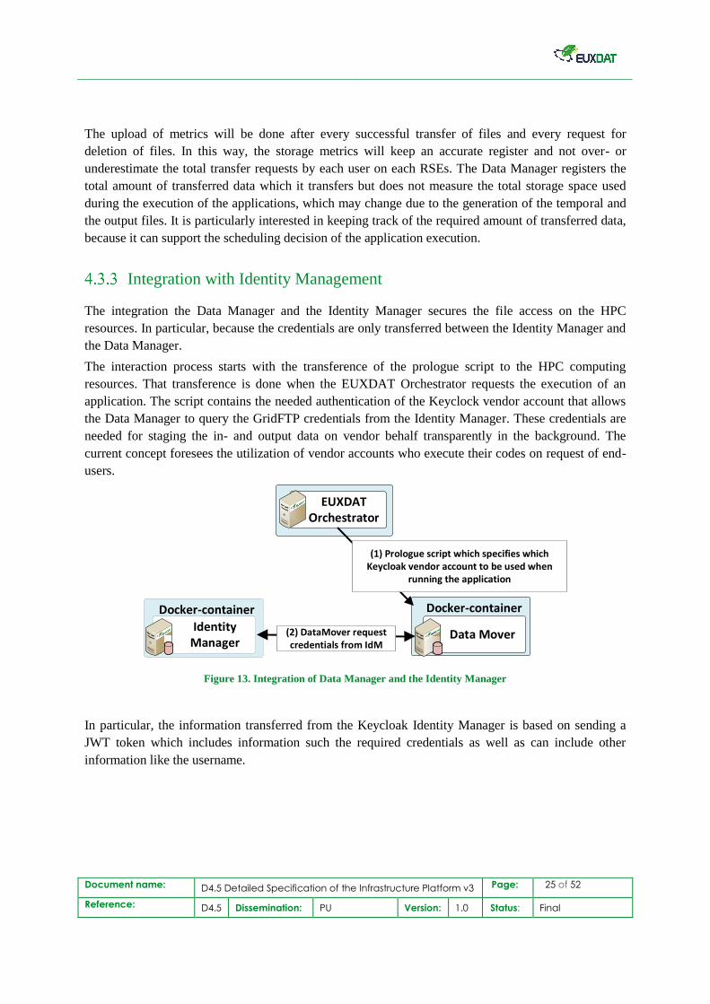
Integration with Identity Management
The integration the Data Manager and the Identity Manager secures the file access on the HPC
resources. In particular, because the credentials are only transferred between the Identity Manager and
the Data Manager.
The interaction process starts with the transference of the prologue script to the HPC computing
resources. That transference is done when the EUXDAT Orchestrator requests the execution of an
application. The script contains the needed authentication of the Keyclock vendor account that allows
the Data Manager to query the GridFTP credentials from the Identity Manager. These credentials are
needed for staging the in- and output data on vendor behalf transparently in the background. The
current concept foresees the utilization of vendor accounts who execute their codes on request of end-
users.
Docker-container
IdentityManager
EUXDAT Orchestrator
Docker-container
Data Mover(2) DataMover request credentials from IdM
(1) Prologue script which specifies which Keycloak vendor account to be used when
running the application
Figure 13. Integration of Data Manager and the Identity Manager
In particular, the information transferred from the Keycloak Identity Manager is based on sending a
JWT token which includes information such the required credentials as well as can include other
information like the username.
Document name: D4.5 Detailed Specification of the Infrastructure Platform v3 Page: 26 of 52
Reference: D4.5 Dissemination: PU Version: 1.0 Status: Final
4.4 Monitoring
The EUXDAT monitoring system using Prometheus5 to save the metric data and Grafana6 to
display it is described in previous deliverables D4.4 [16].
In section 4.1 of this deliverable we describe the integration between RUCIO and the
orchestrator. Furthermore, RUCIO will provide some metrics that we plan to collect, and
there is detailed information about RUCIO monitoring at [24].
The most interesting data for EUXDAT monitoring related to RUCIO metrics are:
1. size of the files stored
2. total amount of data stored on each RSE
3. total amount of data stored by the users, however no information about latency or
bandwidth
In near future we will estimate the storage needs to save this metric data in the server in order
to decide whether it is more convenient to save all the RUCIO metrics or select the most
important metrics to save.
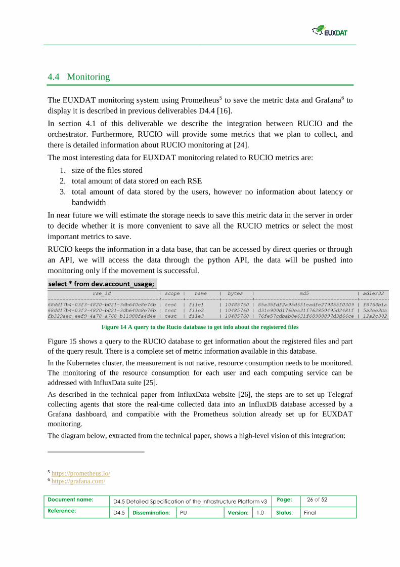
RUCIO keeps the information in a data base, that can be accessed by direct queries or through
an API, we will access the data through the python API, the data will be pushed into
monitoring only if the movement is successful.
Figure 14 A query to the Rucio database to get info about the registered files
Figure 15 shows a query to the RUCIO database to get information about the registered files and part
of the query result. There is a complete set of metric information available in this database.
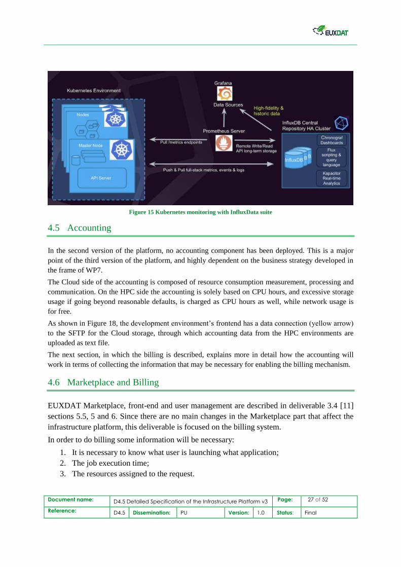
In the Kubernetes cluster, the measurement is not native, resource consumption needs to be monitored.
The monitoring of the resource consumption for each user and each computing service can be
addressed with InfluxData suite [25].
As described in the technical paper from InfluxData website [26], the steps are to set up Telegraf
collecting agents that store the real-time collected data into an InfluxDB database accessed by a
Grafana dashboard, and compatible with the Prometheus solution already set up for EUXDAT
monitoring.
The diagram below, extracted from the technical paper, shows a high-level vision of this integration:
5 https://prometheus.io/ 6 https://grafana.com/
Document name: D4.5 Detailed Specification of the Infrastructure Platform v3 Page: 27 of 52
Reference: D4.5 Dissemination: PU Version: 1.0 Status: Final
Figure 15 Kubernetes monitoring with InfluxData suite
4.5 Accounting
In the second version of the platform, no accounting component has been deployed. This is a major
point of the third version of the platform, and highly dependent on the business strategy developed in
the frame of WP7.
The Cloud side of the accounting is composed of resource consumption measurement, processing and
communication. On the HPC side the accounting is solely based on CPU hours, and excessive storage
usage if going beyond reasonable defaults, is charged as CPU hours as well, while network usage is
for free.
As shown in Figure 18, the development environment’s frontend has a data connection (yellow arrow)
to the SFTP for the Cloud storage, through which accounting data from the HPC environments are
uploaded as text file.
The next section, in which the billing is described, explains more in detail how the accounting will
work in terms of collecting the information that may be necessary for enabling the billing mechanism.
4.6 Marketplace and Billing
EUXDAT Marketplace, front-end and user management are described in deliverable 3.4 [11]
sections 5.5, 5 and 6. Since there are no main changes in the Marketplace part that affect the
infrastructure platform, this deliverable is focused on the billing system.
In order to do billing some information will be necessary:
1. It is necessary to know what user is launching what application;
2. The job execution time;
3. The resources assigned to the request.
Document name: D4.5 Detailed Specification of the Infrastructure Platform v3 Page: 28 of 52
Reference: D4.5 Dissemination: PU Version: 1.0 Status: Final
The user Id will be available at the Orchestrator which takes it from Keycloak, so once this
information is stored in the orchestrator the accounting collector can query the user Id.
The Orchestrator will know which tasks have been executed and, since the blueprint includes
information about the configuration of the resources required, it is possible to know the
characteristics of the VMs requested and the number of nodes (and their configuration)
requested to the HPC systems (as this is the basic way to account for Cloud resources).
The Monitoring component can provide information about the final usage of resources
(especially in Cloud), the time of execution for jobs and their status (from the Slurm and
Torque exporters) and other information that might be of interest.
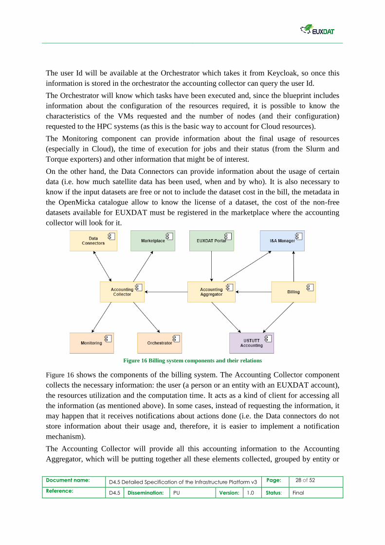
On the other hand, the Data Connectors can provide information about the usage of certain
data (i.e. how much satellite data has been used, when and by who). It is also necessary to
know if the input datasets are free or not to include the dataset cost in the bill, the metadata in
the OpenMicka catalogue allow to know the license of a dataset, the cost of the non-free
datasets available for EUXDAT must be registered in the marketplace where the accounting
collector will look for it.
Figure 16 Billing system components and their relations
Figure 16 shows the components of the billing system. The Accounting Collector component
collects the necessary information: the user (a person or an entity with an EUXDAT account),
the resources utilization and the computation time. It acts as a kind of client for accessing all
the information (as mentioned above). In some cases, instead of requesting the information, it
may happen that it receives notifications about actions done (i.e. the Data connectors do not
store information about their usage and, therefore, it is easier to implement a notification
mechanism).
The Accounting Collector will provide all this accounting information to the Accounting
Aggregator, which will be putting together all these elements collected, grouped by entity or
Document name: D4.5 Detailed Specification of the Infrastructure Platform v3 Page: 29 of 52
Reference: D4.5 Dissemination: PU Version: 1.0 Status: Final
by user, as required. It will allow the possibility to visualize the current accounting status
from the EUXDAT Frontend. It is important to take into account that this will be an
estimation, until all the final accounting (and cost calculation) can be done.
Finally, once we need to do billing, the Billing component will take all the accounting
information and will calculate the cost of each element in the account, according to the
established cost per element.
It is important to mention here that, since USTUTT has its own system for accounting, which
is much more accurate than the proposed solution (as there may be some minor deviations
from the monitored information to the real one). Therefore, EUXDAT will access to the
information in this system, in order to get the real accounting information for users of their
HPC systems.
4.7 Identity Management
As presented in D3.3 [10], Keycloak7 is the component used for centralized user management.
In terms of Identity management, Keycloak supports OAuth/OpenID connect and SAML protocols.
[22]
Concerning EUXDAT end-users’ platform components, most of them are already connected to
Keycloak with Single-Sign-On (SSO): Web portal, scenario dedicated front-end interfaces,
prototyping environment, user workspace.
Concerning EUXDAT End-users’ platform components, most of them are already connected to
Keycloak with Single-Sign-On (SSO): Web portal, scenario dedicated front-end interfaces, File
manager, prototyping environment, user workspace and MarketPlace is planned to be connected.
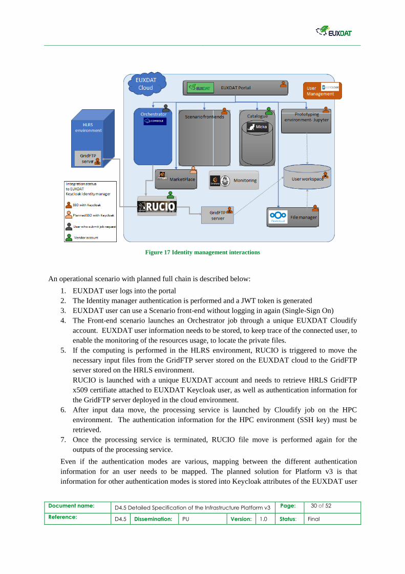
The integration of the different components with Keycloak is presented in Figure 17 below.
7 https://www.keycloak.org/
Document name: D4.5 Detailed Specification of the Infrastructure Platform v3 Page: 30 of 52
Reference: D4.5 Dissemination: PU Version: 1.0 Status: Final
Figure 17 Identity management interactions
An operational scenario with planned full chain is described below:
1. EUXDAT user logs into the portal
2. The Identity manager authentication is performed and a JWT token is generated
3. EUXDAT user can use a Scenario front-end without logging in again (Single-Sign On)
4. The Front-end scenario launches an Orchestrator job through a unique EUXDAT Cloudify
account. EUXDAT user information needs to be stored, to keep trace of the connected user, to
enable the monitoring of the resources usage, to locate the private files.
5. If the computing is performed in the HLRS environment, RUCIO is triggered to move the
necessary input files from the GridFTP server stored on the EUXDAT cloud to the GridFTP
server stored on the HRLS environment.
RUCIO is launched with a unique EUXDAT account and needs to retrieve HRLS GridFTP
x509 certifiate attached to EUXDAT Keycloak user, as well as authentication information for
the GridFTP server deployed in the cloud environment.
6. After input data move, the processing service is launched by Cloudify job on the HPC
environment. The authentication information for the HPC environment (SSH key) must be
retrieved.
7. Once the processing service is terminated, RUCIO file move is performed again for the
outputs of the processing service.
Even if the authentication modes are various, mapping between the different authentication
information for an user needs to be mapped. The planned solution for Platform v3 is that
information for other authentication modes is stored into Keycloak attributes of the EUXDAT user
Document name: D4.5 Detailed Specification of the Infrastructure Platform v3 Page: 31 of 52
Reference: D4.5 Dissemination: PU Version: 1.0 Status: Final
account. Default attribute value size is 255characters but can be easily increased by configuring
the underlying PostgreSQL database.
4.8 Application Repository
The EUXDAT Application Repository is not a real component, but more a logical concept. Data from
external query-based interfaces is copied into the EUXDAT hosting environment’s storage, which is
shared with the Cloud compute environment.
The Application Repository is basically a shared file-system, with a GridFTP endpoint for data staging
from and to the HPC/HPDA environments. Input data for workloads is referenced with the help of
Cloudify blueprints.
4.9 Data Repository
The EUXDAT Data Repository is, similarly to the application repository, not a real component, but
more a logical concept. Data from external query-based interfaces is copied into the EUXDAT hosting
environment’s storage, which is shared with the Cloud compute environment.
The Data Repository is basically a shared file-system, with a GridFTP endpoint for data staging from
and to the HPC/HPDA environments. Input data for workloads is referenced with the help of Cloudify
blueprints.
Document name: D4.5 Detailed Specification of the Infrastructure Platform v3 Page: 32 of 52
Reference: D4.5 Dissemination: PU Version: 1.0 Status: Final
5. Development Infrastructure
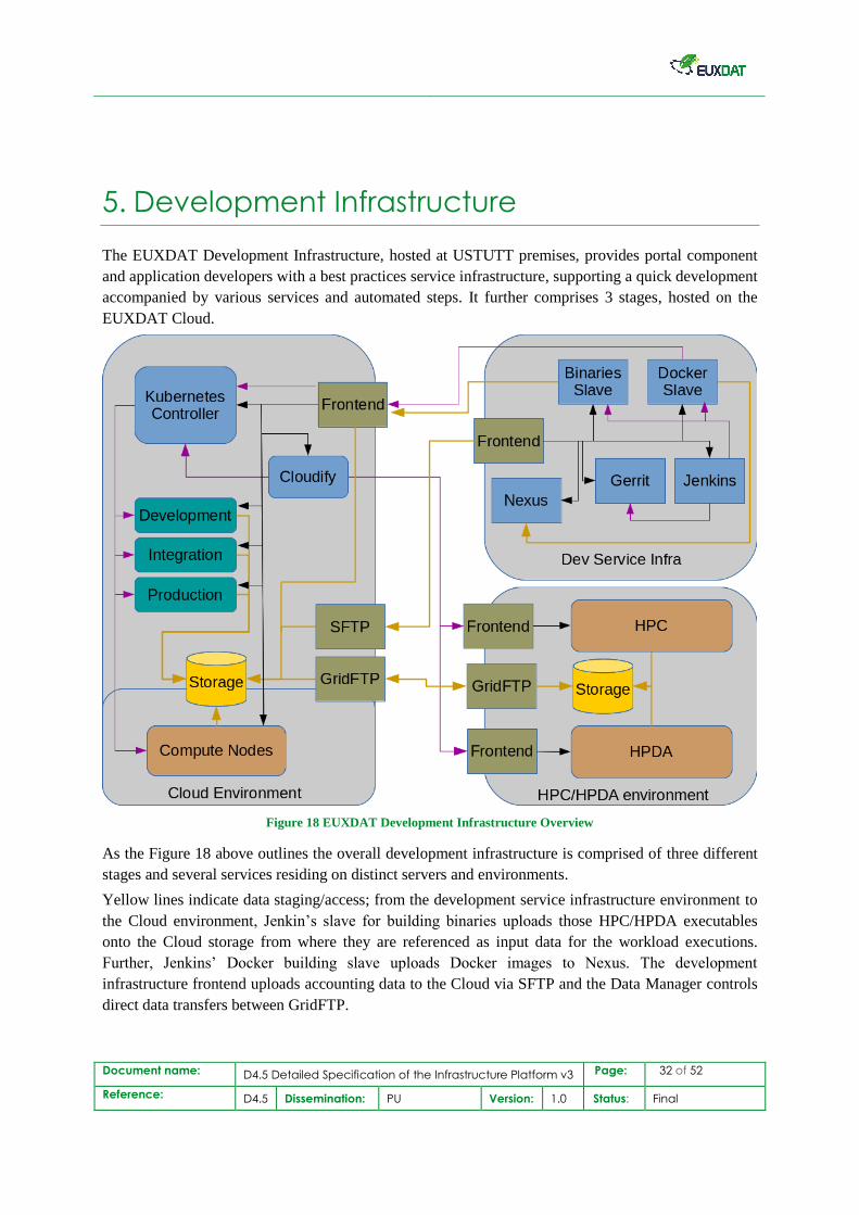
The EUXDAT Development Infrastructure, hosted at USTUTT premises, provides portal component
and application developers with a best practices service infrastructure, supporting a quick development
accompanied by various services and automated steps. It further comprises 3 stages, hosted on the
EUXDAT Cloud.
Figure 18 EUXDAT Development Infrastructure Overview
As the Figure 18 above outlines the overall development infrastructure is comprised of three different
stages and several services residing on distinct servers and environments.
Yellow lines indicate data staging/access; from the development service infrastructure environment to
the Cloud environment, Jenkin’s slave for building binaries uploads those HPC/HPDA executables
onto the Cloud storage from where they are referenced as input data for the workload executions.
Further, Jenkins’ Docker building slave uploads Docker images to Nexus. The development
infrastructure frontend uploads accounting data to the Cloud via SFTP and the Data Manager controls
direct data transfers between GridFTP.
Document name: D4.5 Detailed Specification of the Infrastructure Platform v3 Page: 33 of 52
Reference: D4.5 Dissemination: PU Version: 1.0 Status: Final
The purple lines are service communications; Docker slave deploys image via Kubernetes, Kubernetes
manages the three stages (dev/int/prod) and Cloud compute, Cloudify delegates workload submission
for the Cloud and HPC/HPDA environment, Jenkins gets triggered by Gerrit.
Black lines indicate SSH connectivity to reach hosts.
Few changes had to be applied to the previously specified architecture, e.g. a “Sonatype Nexus
Repository Manager”8 service has been added, to manage all the Docker9 images. Also, the staging
concept, or to be more exact the location of the development and integration stages, had to be adopted
to technical challenges and the corresponding details are highlighted in subsection 5.2. In addition to
the newly introduced Nexus Docker repository service, existing build server resources (Jenkins slaves)
have been upgraded to better match the current (and future) needs and speed up builds and
deployments.
5.1 Infrastructure Services
All the services provided for development purposes are encapsulated in virtual machines, hosted on
one physical server in an environment logically and physically separated from the Cloud hosting,
Cloud compute, and HPC/HPDA compute environments.
The physical VM host has no public IP address, but the frontend VM, only. It enables access to the
rest of the machines, with the help of iptables10 based port forwarding to Gerrit and with the help of
Nginx11 as https-proxy forwarding traffic to Jenkins, Nexus and Gerrit’s web-interfaces, besides
service the git repos via HTTPS and gitweb12.
What functionality each of the services in particular provides, and how they are interconnected with
other services, is explained in the succeeding subsections.
Source Code Repositories (Git)
For source code management (SCM), there is a git server in place on the frontend VM (eufe.hlrs.de),
hosting repositories for each of the components developed within EUXDAT. In addition, there is a
backup server (projects.hlrs.de) to which the stable branches are replicated. Gerrit13 code review
service also holds local copies of each git repository for code under review and to be merged.
Developers are not expected to push any code directly to the stable repositories on the frontend, but
instead utilize the workflows described in section 5.4 and push their code to Gerrit.
8 https://www.sonatype.com/product-nexus-repository 9 https://www.docker.com/ 10 https://wiki.debian.org/iptables 11 https://www.nginx.com/ 12 https://git-scm.com/docs/gitweb 13 https://www.gerritcodereview.com/
Document name: D4.5 Detailed Specification of the Infrastructure Platform v3 Page: 34 of 52
Reference: D4.5 Dissemination: PU Version: 1.0 Status: Final
The git repositories on the frontend are accessible via SSH, but also via HTTPS, and further there is a
git web UI available making the stable repositories accessible via a common web-browser, too.
In the following an overview about the existing code repositories and their purpose, divided into
several categories for a better understanding.
Meta Project Repository
Bundles all development in EUXDAT into one meta project which links the individual repositories as
submodules.
EUXDAT
Platform Component Repositories
EUXDAT-datamover
EUXDAT-marketplace
EUXDAT-monitoring
EUXDAT-orchestrator
Common Code Repositories
EUXDAT-tools
Pilot and Scenario repositories
pilot-agroclimatic_zone
pilot-cri2_model_v1
pilot-open_land_use
sc1_morphometry
sc2_crop_status
sc3_agroclimatic
sc4_climatic_patterns
sc5_field_use_rec
sc6_eff_util_resources
sc7_crop_growth_stage
sc8_effects_insects
Document name: D4.5 Detailed Specification of the Infrastructure Platform v3 Page: 35 of 52
Reference: D4.5 Dissemination: PU Version: 1.0 Status: Final
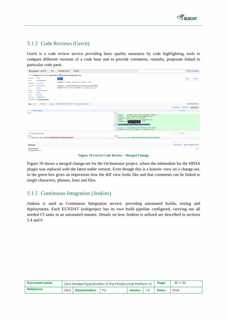
Code Reviews (Gerrit)
Gerrit is a code review service providing basic quality assurance by code highlighting, tools to
compare different versions of a code base and to provide comments, remarks, proposals linked to
particular code parts.
Figure 19 Gerrit Code Review - Merged Change
Figure 19 shows a merged change-set for the Orchestrator project, where the submodule for the HPDA
plugin was replaced with the latest stable version. Even though this is a historic view on a change-set,
in the green box gives an impression how the diff view looks like and that comments can be linked to
single characters, phrases, lines and files.
Continuous Integration (Jenkins)
Jenkins is used as Continuous Integration service, providing automated builds, testing and
deployments. Each EUXDAT (sub)project has its own build pipeline configured, carrying out all
needed CI tasks in an automated manner. Details on how Jenkins is utilized are described in sections
5.4 and 6
Document name: D4.5 Detailed Specification of the Infrastructure Platform v3 Page: 36 of 52
Reference: D4.5 Dissemination: PU Version: 1.0 Status: Final
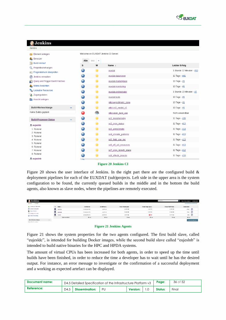
Figure 20 Jenkins CI
Figure 20 shows the user interface of Jenkins. In the right part there are the configured build &
deployment pipelines for each of the EUXDAT (sub)projects. Left side in the upper area is the system
configuration to be found, the currently queued builds in the middle and in the bottom the build
agents, also known as slave nodes, where the pipelines are remotely executed.
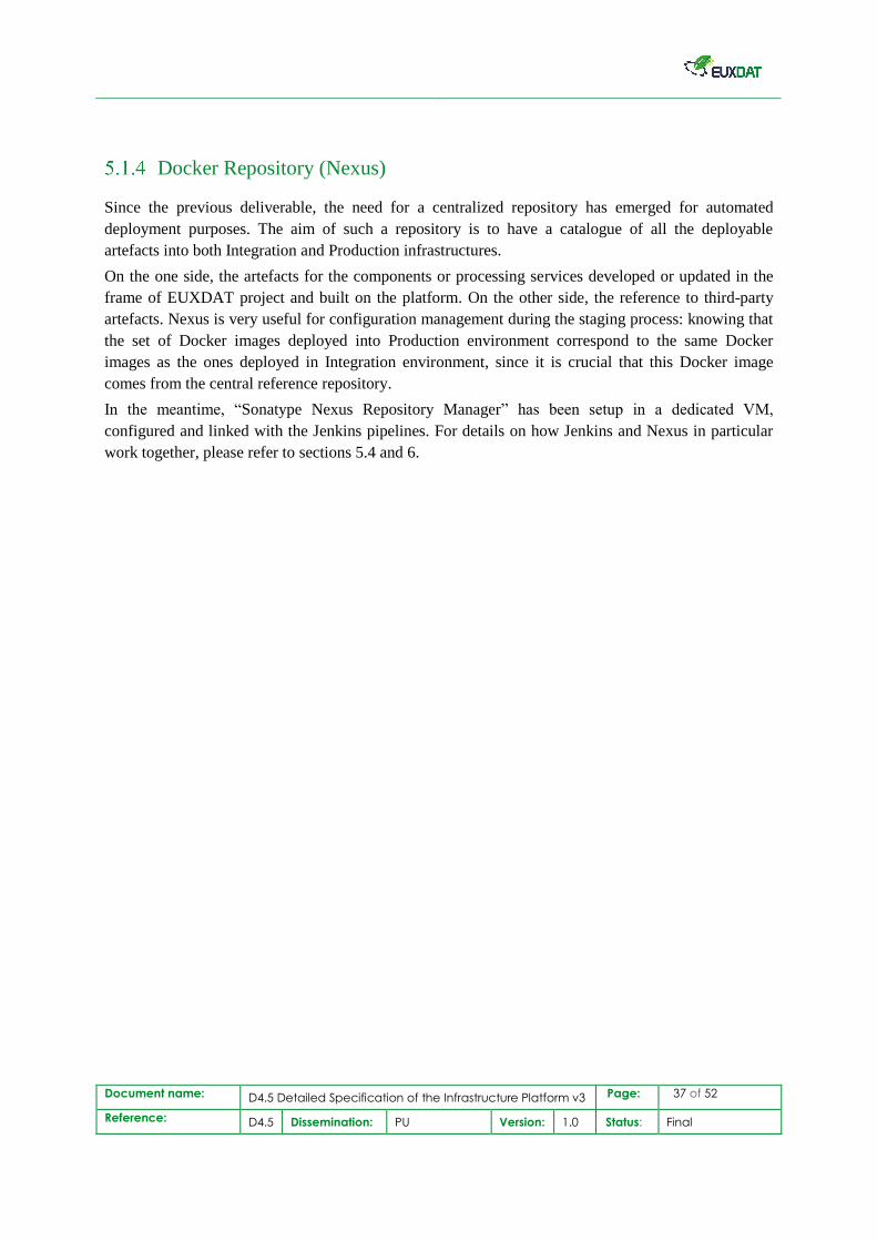
Figure 21 Jenkins Agents
Figure 21 shows the system properties for the two agents configured. The first build slave, called
“eujesldc”, is intended for building Docker images, while the second build slave called “eujeslnb” is
intended to build native binaries for the HPC and HPDA systems.
The amount of virtual CPUs has been increased for both agents, in order to speed up the time until
builds have been finished, in order to reduce the time a developer has to wait until he has the desired
output. For instance, an error message to investigate or the confirmation of a successful deployment
and a working as expected artefact can be displayed.
Document name: D4.5 Detailed Specification of the Infrastructure Platform v3 Page: 37 of 52
Reference: D4.5 Dissemination: PU Version: 1.0 Status: Final
Docker Repository (Nexus)
Since the previous deliverable, the need for a centralized repository has emerged for automated
deployment purposes. The aim of such a repository is to have a catalogue of all the deployable
artefacts into both Integration and Production infrastructures.
On the one side, the artefacts for the components or processing services developed or updated in the
frame of EUXDAT project and built on the platform. On the other side, the reference to third-party
artefacts. Nexus is very useful for configuration management during the staging process: knowing that
the set of Docker images deployed into Production environment correspond to the same Docker
images as the ones deployed in Integration environment, since it is crucial that this Docker image
comes from the central reference repository.
In the meantime, “Sonatype Nexus Repository Manager” has been setup in a dedicated VM,
configured and linked with the Jenkins pipelines. For details on how Jenkins and Nexus in particular
work together, please refer to sections 5.4 and 6.
Document name: D4.5 Detailed Specification of the Infrastructure Platform v3 Page: 38 of 52
Reference: D4.5 Dissemination: PU Version: 1.0 Status: Final
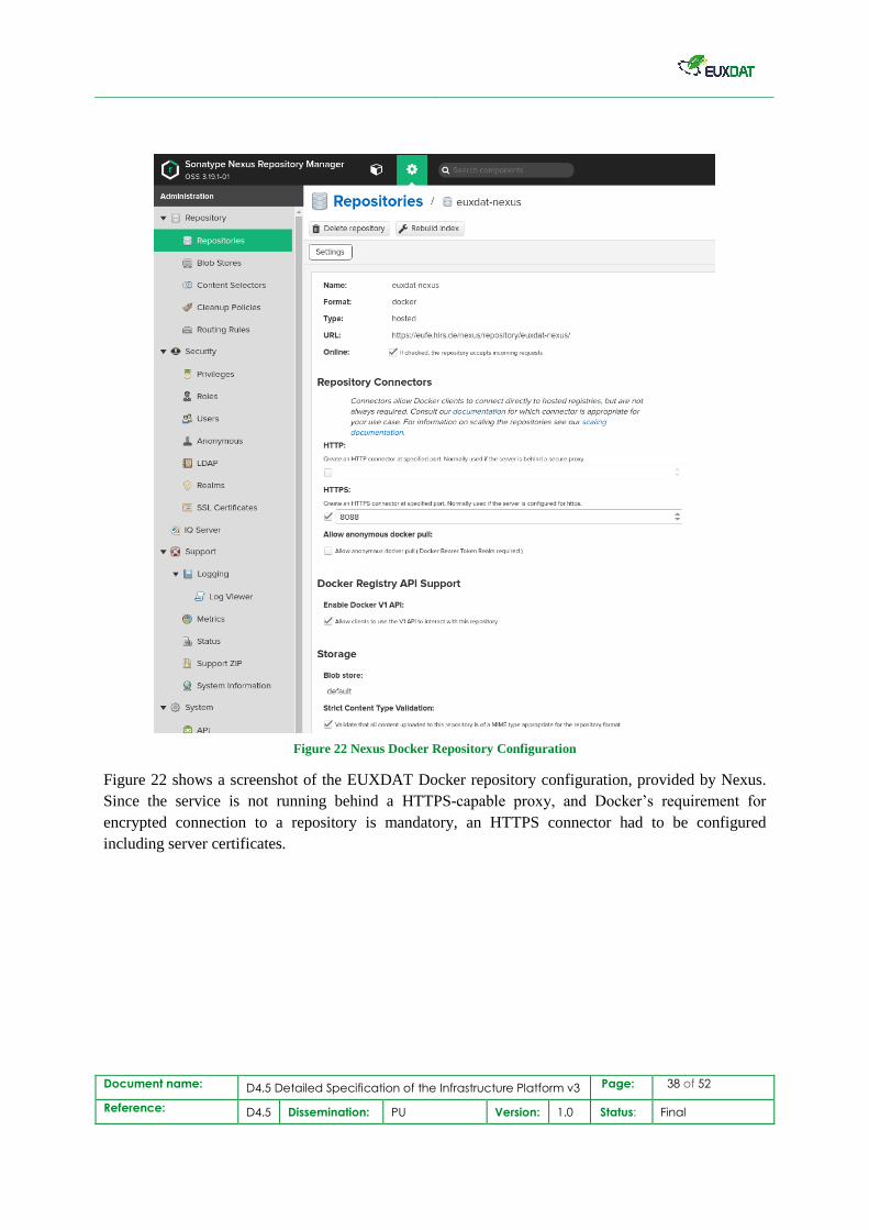
Figure 22 Nexus Docker Repository Configuration
Figure 22 shows a screenshot of the EUXDAT Docker repository configuration, provided by Nexus.
Since the service is not running behind a HTTPS-capable proxy, and Docker’s requirement for
encrypted connection to a repository is mandatory, an HTTPS connector had to be configured
including server certificates.
Document name: D4.5 Detailed Specification of the Infrastructure Platform v3 Page: 39 of 52
Reference: D4.5 Dissemination: PU Version: 1.0 Status: Final
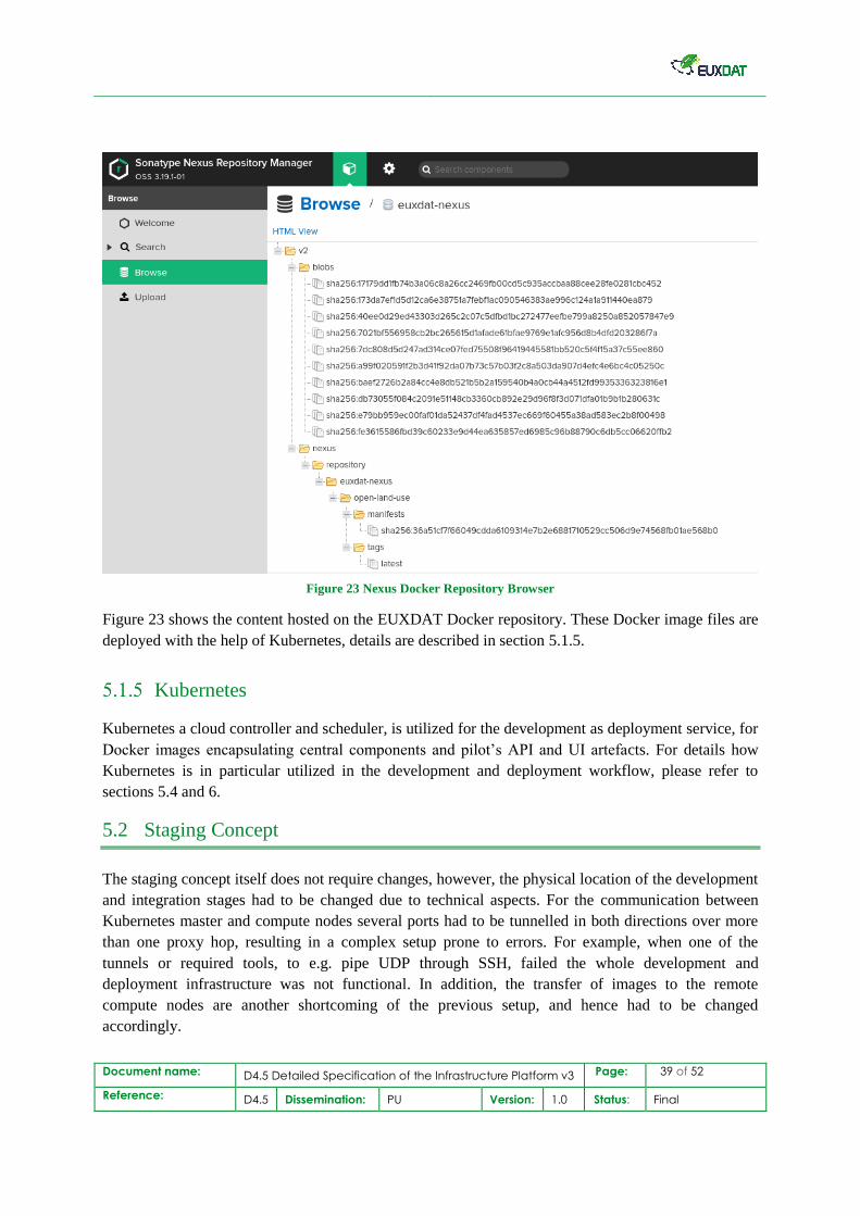
Figure 23 Nexus Docker Repository Browser
Figure 23 shows the content hosted on the EUXDAT Docker repository. These Docker image files are
deployed with the help of Kubernetes, details are described in section 5.1.5.
Kubernetes
Kubernetes a cloud controller and scheduler, is utilized for the development as deployment service, for
Docker images encapsulating central components and pilot’s API and UI artefacts. For details how
Kubernetes is in particular utilized in the development and deployment workflow, please refer to
sections 5.4 and 6.
5.2 Staging Concept
The staging concept itself does not require changes, however, the physical location of the development
and integration stages had to be changed due to technical aspects. For the communication between
Kubernetes master and compute nodes several ports had to be tunnelled in both directions over more
than one proxy hop, resulting in a complex setup prone to errors. For example, when one of the
tunnels or required tools, to e.g. pipe UDP through SSH, failed the whole development and
deployment infrastructure was not functional. In addition, the transfer of images to the remote
compute nodes are another shortcoming of the previous setup, and hence had to be changed
accordingly.
Document name: D4.5 Detailed Specification of the Infrastructure Platform v3 Page: 40 of 52
Reference: D4.5 Dissemination: PU Version: 1.0 Status: Final
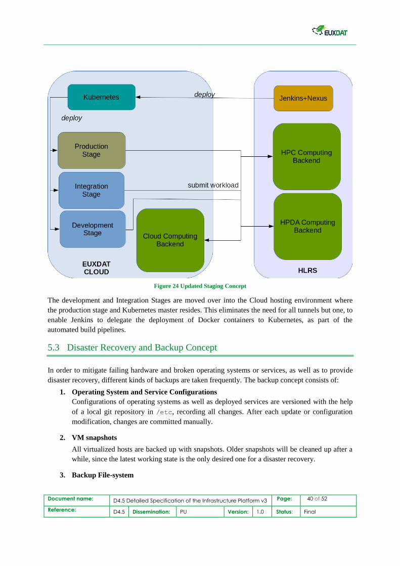
Figure 24 Updated Staging Concept
The development and Integration Stages are moved over into the Cloud hosting environment where
the production stage and Kubernetes master resides. This eliminates the need for all tunnels but one, to
enable Jenkins to delegate the deployment of Docker containers to Kubernetes, as part of the
automated build pipelines.
5.3 Disaster Recovery and Backup Concept
In order to mitigate failing hardware and broken operating systems or services, as well as to provide
disaster recovery, different kinds of backups are taken frequently. The backup concept consists of:
1. Operating System and Service Configurations
Configurations of operating systems as well as deployed services are versioned with the help
of a local git repository in /etc, recording all changes. After each update or configuration
modification, changes are committed manually.
2. VM snapshots
All virtualized hosts are backed up with snapshots. Older snapshots will be cleaned up after a
while, since the latest working state is the only desired one for a disaster recovery.
3. Backup File-system
Document name: D4.5 Detailed Specification of the Infrastructure Platform v3 Page: 41 of 52
Reference: D4.5 Dissemination: PU Version: 1.0 Status: Final
There is a dedicated storage for backups on the physical host (for details refer to section 5.1), a
ZFS14 raid mounted on all physical server as /backup. Copies of the server’s operating
system and service configurations (local Git repository) and service data (e.g. databases) are
stored there. Further, redundant copies of VM snapshots are stored there as well. The File-
system itself is setup with striping and backup disks and thus is tolerant against single drives
failing and capable to restore data reliably in such cases.
4. Automated cron job steered Backups
All backups of local git repositories, service data and VM snapshots are copied frequently to
the ZFS backup file-system. These tasks are automated with the help of Linux cron15 jobs and
need no manual interaction. Older backups are kept for some time before being wiped, as their
value and importance lowers with each succeeding backup of working services and machines
taken.
In case backups are needed to restore broken services or systems, the task has to be carried out
manually by administrators, after investigating what is broken. Alternatively, a reset to the last
snapshot date, which, however, may have an impact on data written and modified in the
meantime.
5.4 Workflows
Within the EUXDAT project there are two types of developments taking place, slightly different in
their nature. There is on the one hand the development of the EUXDAT Portal Components, and on
the other hand the development of pilot applications making use of the computation backends.
The development workflow is for both differs in minor aspects, while having common steps on an
abstract level.
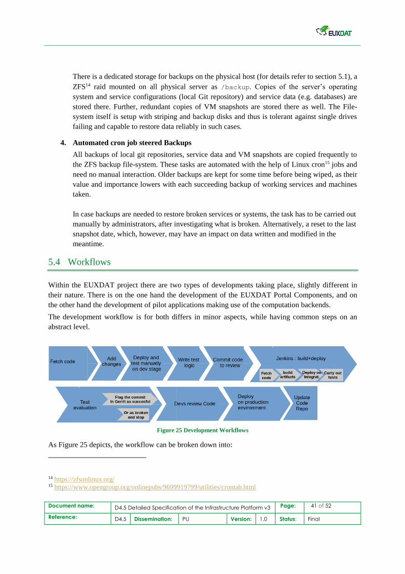
Figure 25 Development Workflows
As Figure 25 depicts, the workflow can be broken down into:
14 https://zfsonlinux.org/ 15 https://www.opengroup.org/onlinepubs/9699919799/utilities/crontab.html
Document name: D4.5 Detailed Specification of the Infrastructure Platform v3 Page: 42 of 52
Reference: D4.5 Dissemination: PU Version: 1.0 Status: Final
1. Fetch latest code from Git (origin repository)
2. Add changes
3. Deploy and test manually on development stage, fix the code if needed
4. Write test logic for new functions.
5. Commit code update for review to Gerrit
6. Jenkins gets triggered by Gerrit, and the build+test pipeline is started
a. Fetch code
b. Build artefacts
c. Deploy on integration stage
d. Carry out tests
7. Test Evaluation
a. Flag the commit in Gerrit as successful, continue with step 7
b. Or as broken and stop in this case
8. Developers review the updated code; several iterations may be needed until approved
9. Artefacts are deployed on the production environment (for details refer to section 6)
10. Code in the Git (origin repository) is updated
Component Development
A component development workflow does not comprise the development of Web-UI, since the
components developed are transparent to the user, carrying out invisible background tasks, for
instance, such as monitoring or workload deployment on the computation backends.
This makes the overall process simpler than for pilot development. The actual difference is in the step
3 of the workflow highlighted in section 5.4.
The designed workflow for component developers is as follows:
1. Artefacts are manually deployed on the development stage
2. Artefacts are tested manually (test suite execution, ad hoc testing of new functionality)
3. Test case is written and added to the regression testing suite
4. Code submitted for review
Pilot Development
The pilot application development differs from the portal component development in few aspects. A
pilot application consists of three building blocks:
1. End-User Web-Interface
2. RESTful platform APIs
3. Application logic for the actual computations.
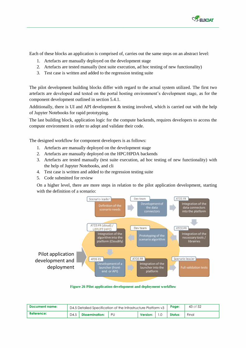
Document name: D4.5 Detailed Specification of the Infrastructure Platform v3 Page: 43 of 52
Reference: D4.5 Dissemination: PU Version: 1.0 Status: Final
Each of these blocks an application is comprised of, carries out the same steps on an abstract level:
1. Artefacts are manually deployed on the development stage
2. Artefacts are tested manually (test suite execution, ad hoc testing of new functionality)
3. Test case is written and added to the regression testing suite
The pilot development building blocks differ with regard to the actual system utilized. The first two
artefacts are developed and tested on the portal hosting environment’s development stage, as for the
component development outlined in section 5.4.1.
Additionally, there is UI and API development & testing involved, which is carried out with the help
of Jupyter Notebooks for rapid prototyping.
The last building block, application logic for the compute backends, requires developers to access the
compute environment in order to adopt and validate their code.
The designed workflow for component developers is as follows:
1. Artefacts are manually deployed on the development stage
2. Artefacts are manually deployed on the HPC/HPDA backends
3. Artefacts are tested manually (test suite execution, ad hoc testing of new functionality) with
the help of Jupyter Notebooks, and cli
4. Test case is written and added to the regression testing suite
5. Code submitted for review
On a higher level, there are more steps in relation to the pilot application development, starting
with the definition of a scenario:
Figure 26 Pilot application development and deployment workflow
Pilot applicationdevelopment and
deployment
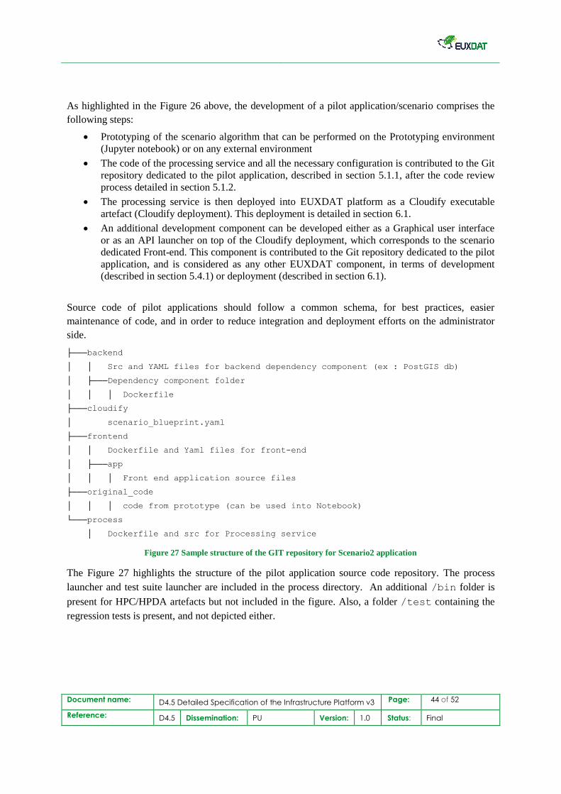
Document name: D4.5 Detailed Specification of the Infrastructure Platform v3 Page: 44 of 52
Reference: D4.5 Dissemination: PU Version: 1.0 Status: Final
As highlighted in the Figure 26 above, the development of a pilot application/scenario comprises the
following steps:
Prototyping of the scenario algorithm that can be performed on the Prototyping environment
(Jupyter notebook) or on any external environment
The code of the processing service and all the necessary configuration is contributed to the Git
repository dedicated to the pilot application, described in section 5.1.1, after the code review
process detailed in section 5.1.2.
The processing service is then deployed into EUXDAT platform as a Cloudify executable
artefact (Cloudify deployment). This deployment is detailed in section 6.1.
An additional development component can be developed either as a Graphical user interface
or as an API launcher on top of the Cloudify deployment, which corresponds to the scenario
dedicated Front-end. This component is contributed to the Git repository dedicated to the pilot
application, and is considered as any other EUXDAT component, in terms of development
(described in section 5.4.1) or deployment (described in section 6.1).
Source code of pilot applications should follow a common schema, for best practices, easier
maintenance of code, and in order to reduce integration and deployment efforts on the administrator
side.
Figure 27 Sample structure of the GIT repository for Scenario2 application
The Figure 27 highlights the structure of the pilot application source code repository. The process
launcher and test suite launcher are included in the process directory. An additional /bin folder is
present for HPC/HPDA artefacts but not included in the figure. Also, a folder /test containing the
regression tests is present, and not depicted either.
├───backend
│ │ Src and YAML files for backend dependency component (ex : PostGIS db)
│ ├───Dependency component folder
│ │ │ Dockerfile
├───cloudify
│ scenario_blueprint.yaml
├───frontend
│ │ Dockerfile and Yaml files for front-end
│ ├───app
│ │ │ Front end application source files
├───original_code
│ │ │ code from prototype (can be used into Notebook)
└───process
│ Dockerfile and src for Processing service
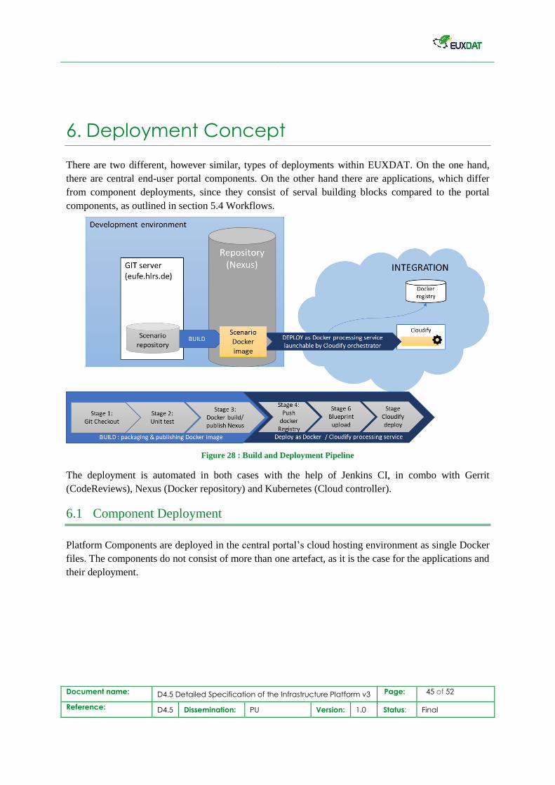
Document name: D4.5 Detailed Specification of the Infrastructure Platform v3 Page: 45 of 52
Reference: D4.5 Dissemination: PU Version: 1.0 Status: Final
6. Deployment Concept
There are two different, however similar, types of deployments within EUXDAT. On the one hand,
there are central end-user portal components. On the other hand there are applications, which differ
from component deployments, since they consist of serval building blocks compared to the portal
components, as outlined in section 5.4 Workflows.
Figure 28 : Build and Deployment Pipeline
The deployment is automated in both cases with the help of Jenkins CI, in combo with Gerrit
(CodeReviews), Nexus (Docker repository) and Kubernetes (Cloud controller).
6.1 Component Deployment
Platform Components are deployed in the central portal’s cloud hosting environment as single Docker
files. The components do not consist of more than one artefact, as it is the case for the applications and
their deployment.
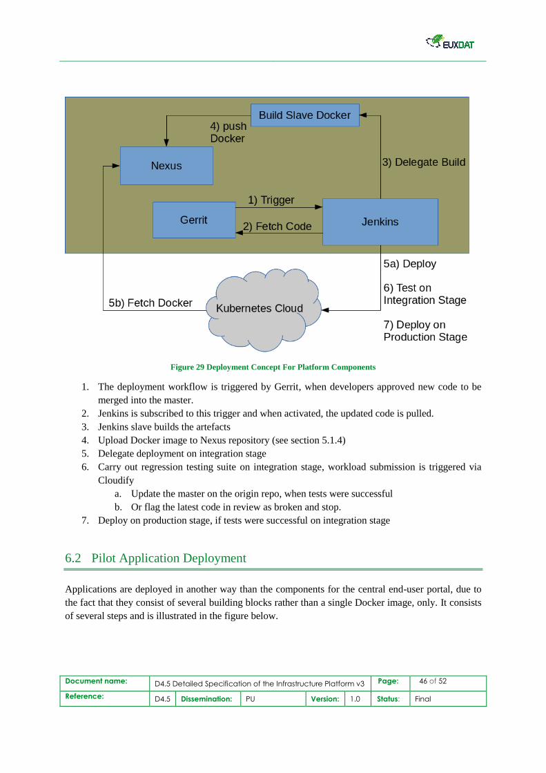
Document name: D4.5 Detailed Specification of the Infrastructure Platform v3 Page: 46 of 52
Reference: D4.5 Dissemination: PU Version: 1.0 Status: Final
Figure 29 Deployment Concept For Platform Components
1. The deployment workflow is triggered by Gerrit, when developers approved new code to be
merged into the master.
2. Jenkins is subscribed to this trigger and when activated, the updated code is pulled.
3. Jenkins slave builds the artefacts
4. Upload Docker image to Nexus repository (see section 5.1.4)
5. Delegate deployment on integration stage
6. Carry out regression testing suite on integration stage, workload submission is triggered via
Cloudify
a. Update the master on the origin repo, when tests were successful
b. Or flag the latest code in review as broken and stop.
7. Deploy on production stage, if tests were successful on integration stage
6.2 Pilot Application Deployment
Applications are deployed in another way than the components for the central end-user portal, due to
the fact that they consist of several building blocks rather than a single Docker image, only. It consists
of several steps and is illustrated in the figure below.
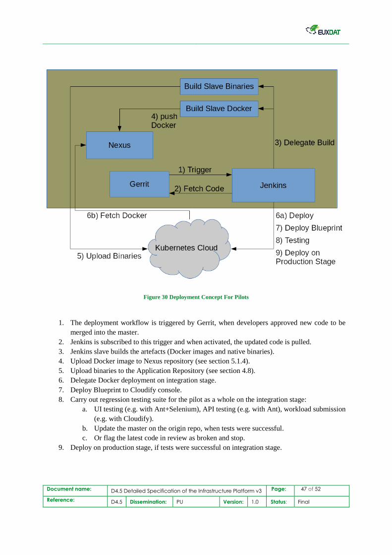
Document name: D4.5 Detailed Specification of the Infrastructure Platform v3 Page: 47 of 52
Reference: D4.5 Dissemination: PU Version: 1.0 Status: Final
Figure 30 Deployment Concept For Pilots
1. The deployment workflow is triggered by Gerrit, when developers approved new code to be
merged into the master.
2. Jenkins is subscribed to this trigger and when activated, the updated code is pulled.
3. Jenkins slave builds the artefacts (Docker images and native binaries).
4. Upload Docker image to Nexus repository (see section 5.1.4).
5. Upload binaries to the Application Repository (see section 4.8).
6. Delegate Docker deployment on integration stage.
7. Deploy Blueprint to Cloudify console.
8. Carry out regression testing suite for the pilot as a whole on the integration stage:
a. UI testing (e.g. with Ant+Selenium), API testing (e.g. with Ant), workload submission
(e.g. with Cloudify).
b. Update the master on the origin repo, when tests were successful.
c. Or flag the latest code in review as broken and stop.
9. Deploy on production stage, if tests were successful on integration stage.
Document name: D4.5 Detailed Specification of the Infrastructure Platform v3 Page: 48 of 52
Reference: D4.5 Dissemination: PU Version: 1.0 Status: Final
7. Conclusions
This deliverable describes the final architecture and design of the EUXDAT e-infrastructure platform
based on previous specification deliverable D4.3 “Detailed Specification of the Infrastructure Platform
v2” [15], as well as accompanying work in WP2 and WP3 D2.6 “EUXDAT e-Infrastructure Definition
v3”, and D3.5 “Detailed Specification of the End Users’ Platform v3” [12].
This document provides an overview of the recent changes and final specification of the EUXDAT
Infrastructure Platform. The platform comprises the end-user portal, compute backends, development
and deployment infrastructure services.
Since this deliverable is written in the third year of the project, EUXDAT platform's e-infrastructure is
moving toward its final stage. Adaption of the presented design may occur as needed, if there are
unforeseen challenges or issues to address, in order to accomplish the mission, and will then be
described in the final follow up deliverable describing the final state.
The document starts with an introduction of the infrastructure platform, consisting of the central
hosting environment and compute backends. Updates and enhancements of the platform’s end-user
portal, and its building components, which came up since the formerly updated specification
documented in D4.3 “Detailed Specification of the Infrastructure Platform v2” [15].
As next the final component architectures and introduction of remaining targeted central platform
service integrations are highlighted, for example such as Data Manager with Monitoring, Orchestrator
with IdentityManagement, or an Accounting and SLA manager.
The following section outlines the needed changes to the development infrastructure addressing
technical challenges by moving the development and integration stages from the development hosting
environment to the cloud hosting environment. New and finalized service architectures and
integrations, intended to support a rapid and automated development workflow, for central
components, as well as (pilot) applications, have been presented. The last part of the document’s main
content focuses on the latest enhancements for the EUXDAT Platform’s deployment infrastructure.
It describes updates for the deployment infrastructure architecture, in particular how the continuous
integration service Jenkins and build pipelines, triggered by Gerrit, are utilized in combination with
Nexus Repository and the Cloud deployment manager Kubernetes, in order to improve the overall
development workflow.
In summary this fifth of six WP4 deliverables describes the latest changes and updates leading to the
final infrastructure specification, which evolved from the initial architecture presented in month 8 in
D4.1 “Detailed Specification of the Infrastructure Platform v1” [13], and its updated version in month
16 in D4.2 “Detailed Specification of the Infrastructure Platform v2” [14]. It lays the foundation for
the final implementation of the EUXDAT e-Infrastructure Platform, to be reported in M30 of the
project "D4.4 Infrastructure Platform v3" [16] at the end of WP4 runtime.
Document name: D4.5 Detailed Specification of the Infrastructure Platform v3 Page: 49 of 52
Reference: D4.5 Dissemination: PU Version: 1.0 Status: Final
8. References
[1] EUXDAT, D2.1 Description of Proposed Pilots and Requirements, Karel Jedlička et al., 2018
[2] EUXDAT, D2.2 EUXDAT e-Infrastructure Definition v1, F. Javier Nieto et al., 2018
[3] EUXDAT, D2.3 Updated Report on e-Infrastructure Requirements v1. Nieto, F. Javier. 2018
[4] EUXDAT, D2.4 e-Infrastructure Definition v2. Nieto, F. Javier. 2019
[5] EUXDAT, D2.5 Updated Report on e-Infrastructure Requirements v2. K. Jedlička 2019
[6] EUXDAT, D3.1 Detailed Specification of the End Users’ Platform v1, Fabien Castel et al.,
2018
[7] EUXDAT, D3.2 Tools & Processes Catalogue and Analytics tools, Fabien Castel et al., 2018
[8] EUXDAT, D3.3 Metadata, Data Catalogue and Data Connectors, WRLS., 2018
[9] EUXDAT D3.2 End Users’ Platform v1, Fabien Castel et al., 2018
[10] EUXDAT D3.3 Detailed Specification of the End Users’ Platform v2, Fabien Castel et al., 2019
[11] EUXDAT D3.4 End Users’ Platform v2, Fabien Castel et al., 2019
[12] EUXDAT D3.5 Detailed Specification of the End Users’ Platform v3, Fabien Castel et al., 2019
[13] EUXDAT, D4.1 Detailed Specification of the Infrastructure Platform v1. M. Gienger. 2018
[14] EUXDAT, D4.2 Infrastructure Platform v1. M. Gienger. 2018
[15] EUXDAT, D4.3 Detailed Specification of the Infrastructure Platform v2. M. Gienger. 2018
[16] EUXDAT, D4.4 Infrastructure Platform v2. D. Hoppe. 2019
[17] EUXDAT. D5.2 EUXDAT e-Infrastructure v1. Castel, Fabien. 2018
[18] EUXDAT. D5.3 EUXDAT Pilot for Land Monitoring and Sustainable Management
implementation v1. CERTH 2018
[19] EUXDAT. D5.4 EUXDAT Detailed Definition of the EUXDAT Pilots and Qualification
Method v2. D. Moshou. 2018
[20] Example of blue-print, available on the GitHub project path: https://github.com/hlrs-121991-
germany/croupier/blob/master/croupier_plugin/tests/blueprints/blueprint_four.yaml, Last
time retrieved 2019-12-10.
Document name: D4.5 Detailed Specification of the Infrastructure Platform v3 Page: 50 of 52
Reference: D4.5 Dissemination: PU Version: 1.0 Status: Final
[21] Source code, examples of use, and installation instructions available on the GitHub project:
https://github.com/prometheus/pushgateway Last time retrieved 2019-12-10. Last time
retrieved 2019-12-10.
[22] Keycloak security documentation
|https://www.keycloak.org/docs/latest/securing_apps/index.html#overview. Last time
retrieved 2019-12-10.
[23] Rucio Python API documentation https://rucio.readthedocs.io/en/latest/api.html. Last time
retrieved 2019-12-10.
[24] Rucio monitoring documentation https://rucio.readthedocs.io/en/latest/monitoring.html. Last
time retrieved 2019-12-10.
[25] InfluxData website: https://www.influxdata.com/solutions/kubernetes-monitoring-solution/ Last
time retrieved 2019-12-10.
[26] InfluxData for Kubernetes monitoring: http://get.influxdata.com/rs/972-GDU-
533/images/Techpaper-InfluxData-Kubernetes-Monitoring-Solution.pdf Last time retrieved
2019-12-10.
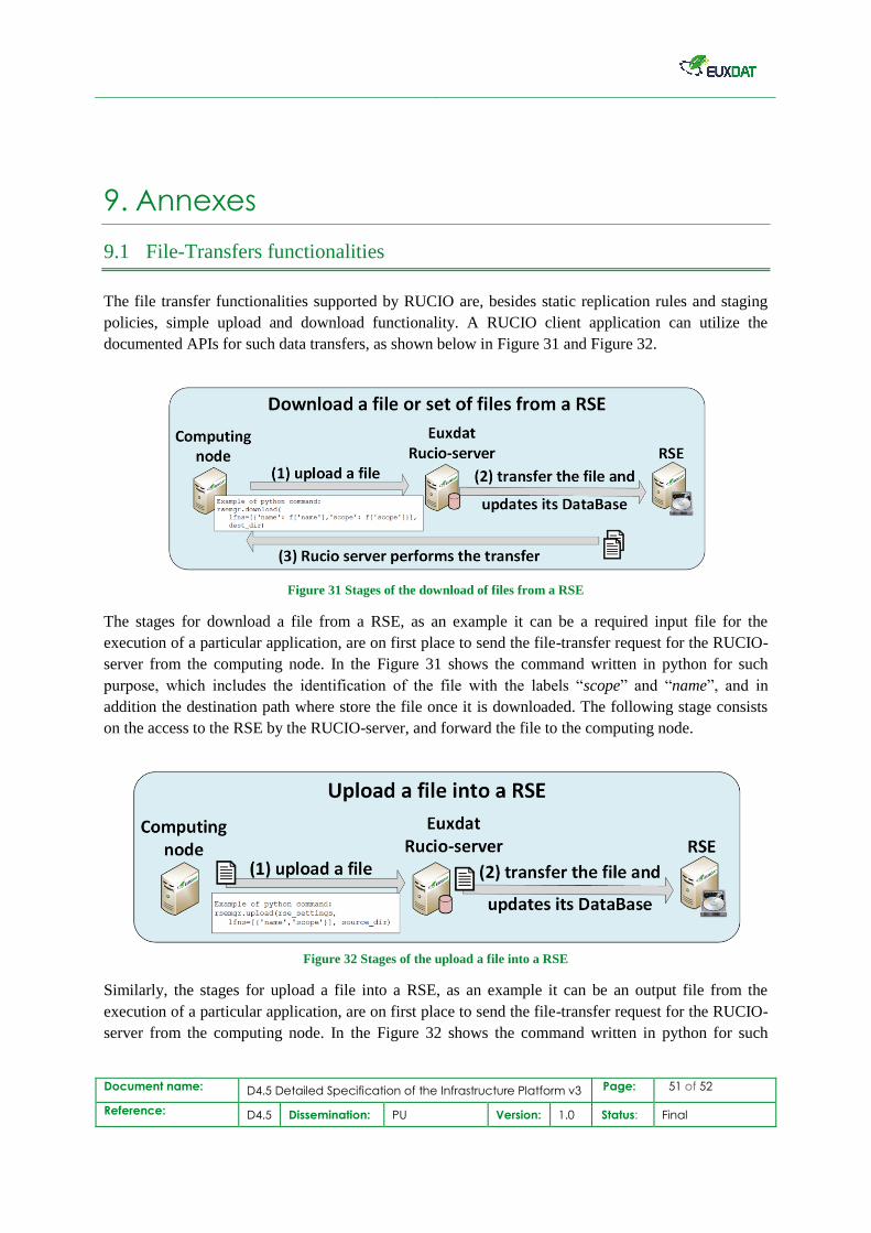
Document name: D4.5 Detailed Specification of the Infrastructure Platform v3 Page: 51 of 52
Reference: D4.5 Dissemination: PU Version: 1.0 Status: Final
9. Annexes
9.1 File-Transfers functionalities
The file transfer functionalities supported by RUCIO are, besides static replication rules and staging
policies, simple upload and download functionality. A RUCIO client application can utilize the
documented APIs for such data transfers, as shown below in Figure 31 and Figure 32.
Figure 31 Stages of the download of files from a RSE
The stages for download a file from a RSE, as an example it can be a required input file for the
execution of a particular application, are on first place to send the file-transfer request for the RUCIO-
server from the computing node. In the Figure 31 shows the command written in python for such
purpose, which includes the identification of the file with the labels “scope” and “name”, and in
addition the destination path where store the file once it is downloaded. The following stage consists
on the access to the RSE by the RUCIO-server, and forward the file to the computing node.
Figure 32 Stages of the upload a file into a RSE
Similarly, the stages for upload a file into a RSE, as an example it can be an output file from the
execution of a particular application, are on first place to send the file-transfer request for the RUCIO-
server from the computing node. In the Figure 32 shows the command written in python for such
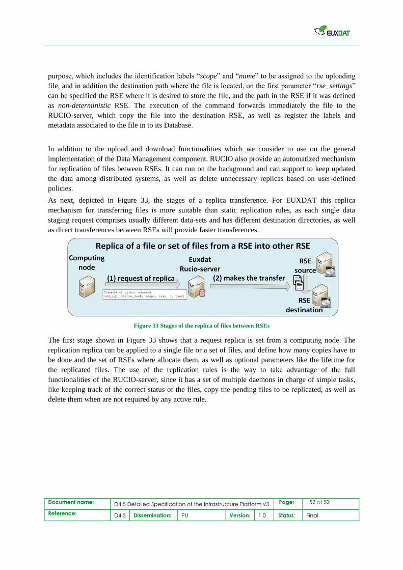
Document name: D4.5 Detailed Specification of the Infrastructure Platform v3 Page: 52 of 52
Reference: D4.5 Dissemination: PU Version: 1.0 Status: Final
purpose, which includes the identification labels “scope” and “name” to be assigned to the uploading
file, and in addition the destination path where the file is located, on the first parameter “rse_settings”
can be specified the RSE where it is desired to store the file, and the path in the RSE if it was defined
as non-deterministic RSE. The execution of the command forwards immediately the file to the
RUCIO-server, which copy the file into the destination RSE, as well as register the labels and
metadata associated to the file in to its Database.
In addition to the upload and download functionalities which we consider to use on the general
implementation of the Data Management component. RUCIO also provide an automatized mechanism
for replication of files between RSEs. It can run on the background and can support to keep updated
the data among distributed systems, as well as delete unnecessary replicas based on user-defined
policies.
As next, depicted in Figure 33, the stages of a replica transference. For EUXDAT this replica
mechanism for transferring files is more suitable than static replication rules, as each single data
staging request comprises usually different data-sets and has different destination directories, as well
as direct transferences between RSEs will provide faster transferences.
Figure 33 Stages of the replica of files between RSEs
The first stage shown in Figure 33 shows that a request replica is set from a computing node. The
replication replica can be applied to a single file or a set of files, and define how many copies have to
be done and the set of RSEs where allocate them, as well as optional parameters like the lifetime for
the replicated files. The use of the replication rules is the way to take advantage of the full
functionalities of the RUCIO-server, since it has a set of multiple daemons in charge of simple tasks,
like keeping track of the correct status of the files, copy the pending files to be replicated, as well as
delete them when are not required by any active rule.