Embed Size (px)
Citation preview
7/30/2019 D43-D47 Seleccion de Bandas
http://slidepdf.com/reader/full/d43-d47-seleccion-de-bandas 1/5
D-43
Stock DriveSelection
TABLE 1 — SERVICE FACTORS
To select the best V-Belt Drive for an application, utilizing stock sheaves, simply follow the step by step instructions below:
BEFORE SELECTING A DRIVE, YOU NEED TO KNOW THESE FACTS:
1. The horsepower requirement of the drive.2. The RPM of the driver.3. The RPM of the driven machine.4. The approximate center distance for the drive.5. Shaft size of both units.6. Average hours of operation per day.
THE CORRECT SERVICE FACTOR IS DETERMINED BY:
1. The extent and frequency of peak loads.
2. The number of operating hours per year, broken down into
averagehours per day of continuousservice.
3. The proper service category, (intermittent, normal or con-
tinuous). Select the one that most closelyapproximates
your application conditions.
INTERMITTENT SERVICE — SERVICE FACTOR 1.0 TO 1.5
a. Light Duty — Not morethan 6 hours per day.
b. Never exceeding rated load.
NORMAL SERVICE — SERVICE FACTOR 1.1 TO 1.6
a. Daily service 6 to 16 hours per day.b. Where occasional starting or peak load does not exceed 200% of the
full load.
CONTINUOUS SERVICE — SERVICE FACTOR 1.2 TO 1.8
a. Continuous service 16 to 24 hours per day.
b. Where start ing or peak load is in excess of 200% of the full load or
where starting or peak loads and overloads occur frequently.
TYPICAL SERVICE FACTORS
DRIVEN MACHINE TYPES DRIVER TYPES
Driven machine types noted below are representative samples only. Select a cate-gory most closely approximating your application from those listed below.
IF IDLERS ARE USED, ADD THE FOLLOWING TO THE SERVICE FACTOR:
Idler on s lack s ide ( inside) NoneIdler on slack side (outside) 0.1
Idler on t ight s ide ( inside) 0.1Idler on t ight s ide (outside) 0.2
ELECTRIC MOTORS:
AC Normal TorqueSquirrel Cageand Synchronous
AC Split PhaseDC Shunt WoundInternal Combustion Engines
ELECTRIC MOTORS:
AC Hi-TorqueAC Hi-SlipAC Repulsion-InductionAC Single Phase
Series WoundAC Slip RingDC Compound Wound
INTERMITTENTSERVICE
NORMALSERVICE
CONTINUOUSSERVICE
INTERMITTENTSERVICE
NORMALSERVICE
CONTINUOUSSERVICE
Agitators for LiquidsBlowers and ExhaustersCentrifugal Pumps and CompressorsFans up to 10 HP
1.0 1.1 1.2 1.1 1.2 1.3
Light Duty Conveyors
Belt Conveyors For Sand, Grain, etc.Dough MixersFans Over 10 HPGeneratorsLine ShaftsLaundry Machinery 1.1 1.2 1.3 1.2 1.3 1.4Machine ToolsPunches-Presses-ShearsPrinting MachineryPositive Displacement Rotary PumpsRevolving and Vibrating Screens
Brick MachineryBucket ElevatorsExcitersPiston CompressorsConveyors (Drag-Pan-Screw)Hammer Mills 1.2 1.3 1.4 1.4 1.5 1.6Paper Mill BeatersPiston PumpsPositive Displacement BlowersPulverizersSaw Mill and Woodworking MachineryTextile Machinery
Crushers (Gyratory-Jaw-Roll)Mills (Ball-Rod-Tube)Hoists 1.3 1.4 1.5 1.5 1.6 1.8Rubber Calenders-Extruders-Mills
Chokable Equipment 2.0 2.0 2.0 2.0 2.0 2.0
FOR A GOOD COMMERCIAL DRIVE SELECTION, USE CONTINUOUS SERVICE FACTOR
INTERMITTENTSERVICE
NORMALSERVICE
CONTINUOUSSERVICE
INTERMITTENTSERVICE
NORMALSERVICE
CONTINUOUSSERVICE
7/30/2019 D43-D47 Seleccion de Bandas
http://slidepdf.com/reader/full/d43-d47-seleccion-de-bandas 2/5
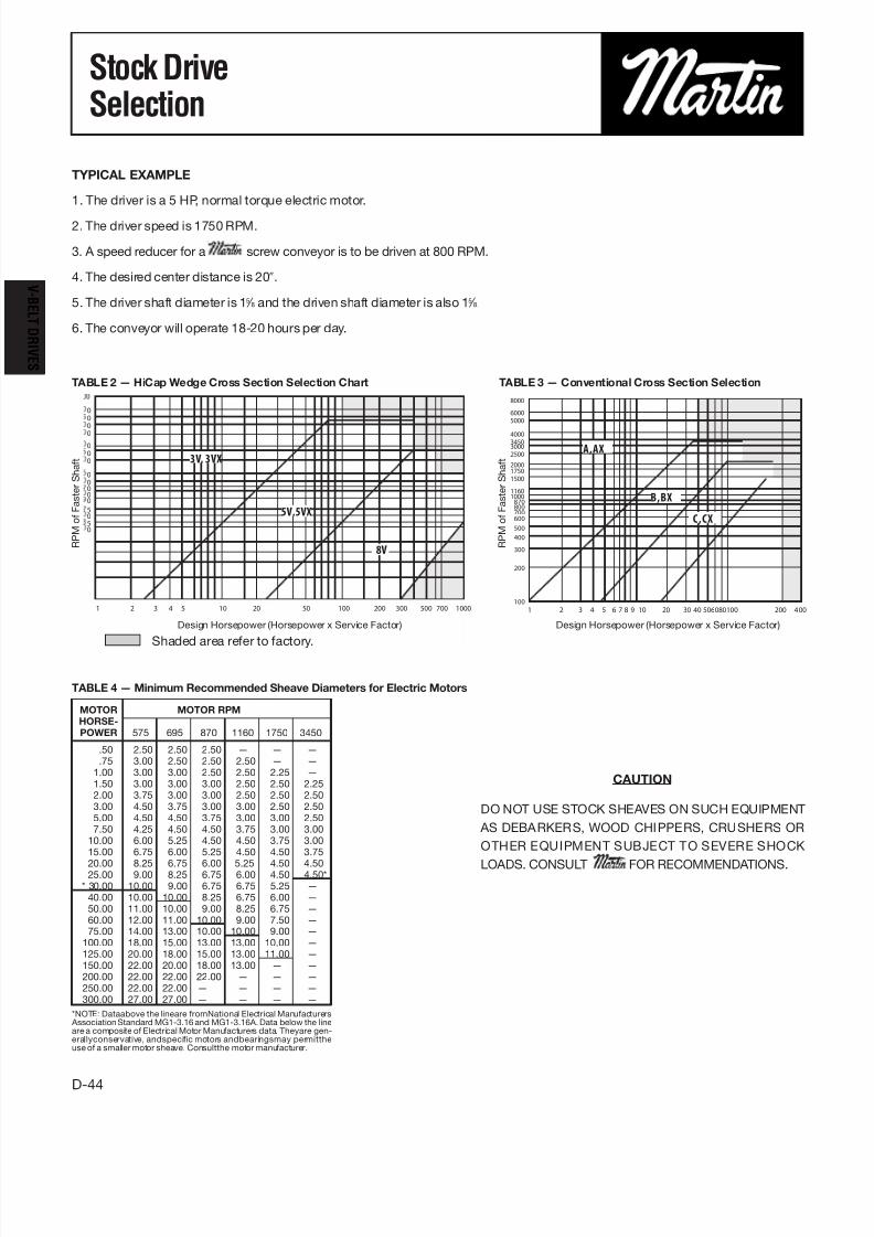
TYPICAL EXAMPLE
1. The driver is a 5 HP, normal torque electric motor.
2. The driver speed is 1750 RPM.
3. A speed reducer for a screw conveyor is to be driven at 800 RPM.
4. The desired center distance is 20″.
5. The driver shaft diameter is 15 ⁄ 8 and the driven shaft diameter is also 15 ⁄ 8.
6. The conveyor will operate 18-20 hours per day.
TABLE 2 — HiCap Wedge Cross Section Selection Chart TABLE 3 — Conventional Cross Section Selection
D-44
Stock DriveSelection
V
BE L T DRIVE S
MOTOR MOTOR RPMHORSE-POWER 575 695 870 1160 1750 3450
.50 2.50 2.50 2.50 — — —
.75 3.00 2.50 2.50 2.50 — —1.00 3.00 3.00 2.50 2.50 2.25 —1.50 3.00 3.00 3.00 2.50 2.50 2.252.00 3.75 3.00 3.00 2.50 2.50 2.503.00 4.50 3.75 3.00 3.00 2.50 2.505.00 4.50 4.50 3.75 3.00 3.00 2.507.50 4.25 4.50 4.50 3.75 3.00 3.00
10.00 6.00 5.25 4.50 4.50 3.75 3.0015.00 6.75 6.00 5.25 4.50 4.50 3.75
20.00 8.25 6.75 6.00 5.25 4.50 4.5025.00 9.00 8.25 6.75 6.00 4.50 4.50** 30.00 10.00 9.00 6.75 6.75 5.25 —
40.00 10.00 10.00 8.25 6.75 6.00 —50.00 11.00 10.00 9.00 8.25 6.75 —60.00 12.00 11.00 10.00 9.00 7.50 —75.00 14.00 13.00 10.00 10.00 9.00 —
100.00 18.00 15.00 13.00 13.00 10.00 —125.00 20.00 18.00 15.00 13.00 11.00 —150.00 22.00 20.00 18.00 13.00 — —200.00 22.00 22.00 22.00 — — —250.00 22.00 22.00 — — — —300.00 27.00 27.00 — — — —
*NOTE: Dataabove the lineare fromNational Electrical Manufacturers AssociationStandard MG1-3.16 and MG1-3.16A. Data below the lineare a composite of Electrical Motor Manufacturers data. Theyare gen-erallyconservative, andspecific motors andbearingsmay permittheuse of a smaller motor sheave. Consultthe motor manufacturer.
CAUTION
DO NOT USE STOCK SHEAVES ON SUCH EQUIPMENT
AS DEBARKERS, WOOD CHIPPERS, CRUSHERS OR
OTHER EQUIPMENT SUBJECT TO SEVERE SHOCK
LOADS. CONSULT FOR RECOMMENDATIONS.
Design Horsepower (Horsepower x Service Factor)
Shaded area refer to factory.
Design Horsepower (Horsepower x Service Factor)
R P M
o f F a s t e r S h a f t
R P M
o f F a s t e r S h a f t
TABLE 4 — Minimum Recommended Sheave Diameters for Electric Motors
0
0
0
0
0
0
0
0
0000
50
50
1 2 3 4 5 10 20 50 100 200 300 500 700 1000
8V
5V,5VX
3V, 3VX
8000
6000
5000
4000
34503000
2500
2000
1750
1500
11601000
870800700
600
500
400
300
200
100
1 2 3 4 5 6 7 8 9 10 20 30 40 506080100 200 4 00
C,CX
B,BX
A,AX
7/30/2019 D43-D47 Seleccion de Bandas
http://slidepdf.com/reader/full/d43-d47-seleccion-de-bandas 3/5
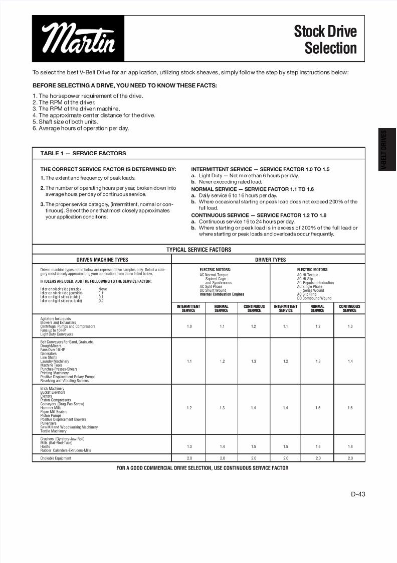
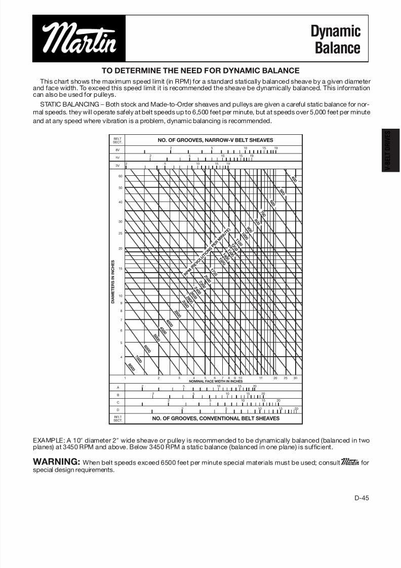
EXAMPLE: A 10″ diameter 2″ wide sheave or pulley is recommended to be dynamically balanced (balanced in twoplanes) at 3450 RPM and above. Below 3450 RPM a static balance (balanced in one plane) is sufficient.
WARNING: When belt speeds exceed 6500 feet per minute special materials must be used; consult Martin forspecial design requirements.
D-45
DynamicBalance
TO DETERMINE THE NEED FOR DYNAMIC BALANCE
This chart shows the maximum speed limit (in RPM) for a standard statically balanced sheave by a given diameterand face width. To exceed this speed limit it is recommended the sheave be dynamically balanced. This informationcan also be used for pulleys.
STATIC BALANCING – Both stock and Made-to-Order sheaves and pulleys are given a careful static balance for nor-
mal speeds. they will operate safely at belt speeds up to 6,500 feet per minute, but at speeds over 5,000 feet per minute
and at any speed where vibration is a problem, dynamic balancing is recommended.
BELTSECT. NO. OF GROOVES, NARROW-V BELT SHEAVES
8V2 5 10 15 19
5V2 5 10 15 19
3V2 5 10 15 19
60
50
40
30
25
20
15
10
9
8
7
6
5
4
NOMINAL FACE WIDTH IN INCHES
A 2 5 10 15 20
B 2 5 10 15 20
C2 5 10 15 20
D 2 5 10 15 20
BELTSECT. NO. OF GROOVES, CONVENTIONAL BELT SHEAVES
1 2 3 4 5 6 7 8 9 10 15 20 25 30
D I A
M E T E R S I N I N C H E S
4 0 0
5 0 0
6 0 0
7 0 0
8 0 0
9 0 0
1 0 0 0 1
1 0 0 1
2 0 0 1
3 0 0 1
4 0 0 1
5 0 0
1 7 5 0
2 0 0 0 2
2 0 0 2
4 0 0 2
6 0
0 2 8 0 0 3
0 0 0
3 5 0 0
4 0 0 0
4 5 0 0
5 0 0 0
6 0 0 0
7 0 0 0
8 0 0 0
R P M ( R E V
O L U T
I O N S
P E R M I N U T
E )
7/30/2019 D43-D47 Seleccion de Bandas
http://slidepdf.com/reader/full/d43-d47-seleccion-de-bandas 4/5
7/30/2019 D43-D47 Seleccion de Bandas
http://slidepdf.com/reader/full/d43-d47-seleccion-de-bandas 5/5
D-47
Stock DriveSelection
NOTE: EQUIPMENT THAT IS SUBJECT
TO HEAVY SHOCK LOAD SUCH AS
ROCK CRUSHERS OR WOOD CHIP-
PERS, USUALLY REQUIRES SPECIAL
CONSTRUCTION.
CONSULT FACTORY FOR RECOMMEN-
DATIONS.
WARNING: BEFORE USING KEVLAR
BELTS, CONSULT FACTORY.
ALTERNATE EXAMPLE
A 25 horsepower, 1160 RPM squirrel cage normal torque electric motor is to drive a fan 315 RPM. The shaft centers should be
about 40″
. The motor has a 2
1
⁄ 8″
shaft and the fan shaft is 2
1
⁄ 4″
. Service is 15 hours per day, constant load.1. Horsepower Requirement of the Drive . . . . . . . . . . . . . . . . . . . . . . . . . . . . . . . . . . . . . . . . . . . . . . . . . . .25 HP
2. RPM of DriveR Shaft . . . . . . . . . . . . . . . . . . . . . . . . . . . . . . . . . . . . . . . . . . . . . . . . . . . . . . . . . . . . .1160 RPM
3. RPM of DriveN Machine . . . . . . . . . . . . . . . . . . . . . . . . . . . . . . . . . . . . . . . . . . . . . . . . . . . . . . . . . . . .315 RPM
4. Approximate Center Distance . . . . . . . . . . . . . . . . . . . . . . . . . . . . . . . . . . . . . . . . . . . . . . . . . . . . . . . . . . . .40″
STEP 1 DETERMINE DESIGN HORSEPOWER
From Table 1 Service Factor 1.2
HP Requirement × Service Factor = Design HP
25 × 1.2 = 30 Design HP
STEP 2 DETERMINE BELT CROSS SECTION
From Table 3 — B
STEP 3 CHECK MINIMUM SMALL SHEAVE DIAMETERFrom Table 4 — 6.75″ min.
STEP 4 SELECT THE DRIVE
Locate the Drive Selection Tables
For B Belts
RPM of Drive — 1160 RPM
Driven Speed — HP per Belt
316 RPM — 8.19 HP per Belt
Required Driver and Driven Sheave
(Re-check minimum)
6.8 Driver
25.0 Driven (6.75″ min.)
Read across to right for shaft centers nearest required center distance. B-128 = 38.9″ centers
Find corrected horsepower by multiplying HP per belt by Arc and Length correction factor. 8.19 × 1.06 = 8.68
Determine number of belts needed by dividing Design HP by corrected HP 30/8.68 = 3.45. Use 4 belts
Order Martin (1) 4 B 68 TB (Driver Sheave)
(1) 2517 21 ⁄ 8 (Bushing)
(1) 4 B 250 TB (Driven Sheave)
(1) 3030 21 ⁄ 4 (Bushing)
(The decision to use Taper Bushed Sheaves was arbitrary.)