Embed Size (px)
Citation preview

SERVICE BULLETINService Bulletin No.: D42L-34-04 Rev 1 Date Issued: 11 October 2012
Title: G1000 System Software Version 1054.03 Update for DA42 L360 Aircraft Page: 1 of 3
1. ATA Code: 3400
2. Effectivity: All DA42 aircraft with TCCA STC SA09-54 or FAA STC SA02725NYinstalled and (Wide Area Augmentation System (WAAS) capable) withGIA 63W LRU installed.
3. General: This Service Bulletin (SB) gives the following:
- A summary of approved software systems, manifests and configurationsfor the Garmin G1000-equipped Diamond DA42 L360 aircraft.
- The authority to install Garmin SB No. 1207.
- This Garmin SB provides information required to update the G1000-equipped Diamond DA42 L360 aircraft with new system software.
NOTE: On aircraft that have a field approved GDL 90 digital data linktransceiver installed, GDL 90 compatability update 2.00 must beinstalled after manual configurations. Contact Customer Supportat Diamond Aircraft in London, Canada for assistance.
Revision 1 of this Service Bulletin adds Garmin Service Bulletin No. 1027,Revision A to the package.
4. Compliance: Compliance with this SB is Optional.
5. Approval: Engineering data referenced or contained in this SB is approved as part ofthe type design.
6. Labour: Approximately 2.5 hours labour will be required to install the GarminSoftware SB, including testing and return-to-service.
This estimate is for direct labour performed by a technician and it does notinclude setup, planning, familiarization, cure time, part fabrication or toolacquisition.
7. Material: Software and concurrent documents can be obtained through your Garmindistributor.
8. Special Tools: Not Applicable
9. References: Garmin Service Bulletin No. 1027, Revision A - dated October 9, 2012(Attached).
SERVICE BULLETINService Bulletin No.: D42L-34-04 Rev 1 Date Issued: 11 October 2012
Title: G1000 System Software Version 1054.03 Update for DA 42 L360 Aircraft Page: 2 of 3
10. Accomplishment Instructions:
10.1 Install this software update in accordance with Garmin SB No. 1207, G1000 SystemSoftware Version 1054.03 Update for G1000-equipped Diamond DA42-L360 Aircraft.
10.2 Must have AFM (Doc # D42L-AFM-002) Revision 7.
10.3 Must have the G1000 Cockpit Reference Guide DA42_L360 (190-01062-02 Rev A - Jan 2012)
10.4 DA42 L360 System Software Version 1054.03 Correlation Check
Compare the installed software system and related manifests with the approved onesshown in the Table 1.
NOTE: It is highly recommended to always use the latest approved software systemwith the related manifests.
NOTE: The current installed system software version appears on the MFD splashscreen during startup.
10.3 Make a log book entry that this SB has been incorporated.
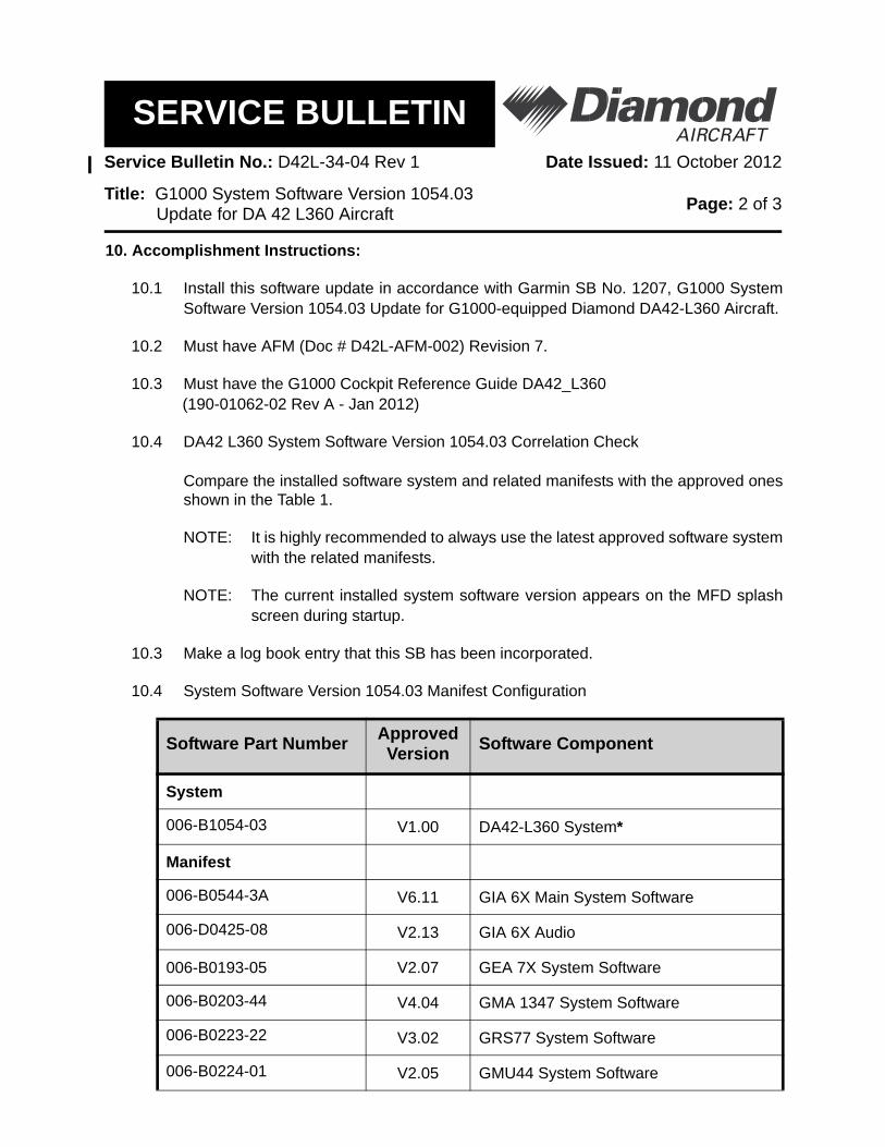
10.4 System Software Version 1054.03 Manifest Configuration
Software Part Number Approved Version Software Component
System
006-B1054-03 V1.00 DA42-L360 System*
Manifest
006-B0544-3A V6.11 GIA 6X Main System Software
006-D0425-08 V2.13 GIA 6X Audio
006-B0193-05 V2.07 GEA 7X System Software
006-B0203-44 V4.04 GMA 1347 System Software
006-B0223-22 V3.02 GRS77 System Software
006-B0224-01 V2.05 GMU44 System Software
SERVICE BULLETINService Bulletin No.: D42L-34-04 Rev 1 Date Issued: 11 October 2012
Title: G1000 System Software Version 1054.03 Update for DA42 L360 Aircraft Page: 3 of 3
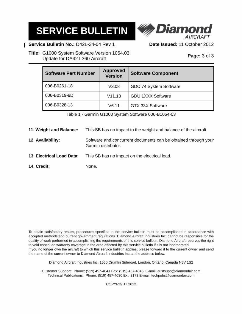
Table 1 - Garmin G1000 System Software 006-B1054-03
11. Weight and Balance: This SB has no impact to the weight and balance of the aircraft.
12. Availability: Software and concurrent documents can be obtained through yourGarmin distributor.
13. Electrical Load Data: This SB has no impact on the electrical load.
14. Credit: None.
To obtain satisfactory results, procedures specified in this service bulletin must be accomplished in accordance withaccepted methods and current government regulations. Diamond Aircraft Industries Inc. cannot be responsible for thequality of work performed in accomplishing the requirements of this service bulletin. Diamond Aircraft reserves the rightto void continued warranty coverage in the area affected by this service bulletin if it is not incorporated.If you no longer own the aircraft to which this service bulletin applies, please forward it to the current owner and sendthe name of the current owner to Diamond Aircraft Industries Inc. at the address below.
Diamond Aircraft Industries Inc. 1560 Crumlin Sideroad, London, Ontario, Canada N5V 1S2
Customer Support: Phone: (519) 457-4041 Fax: (519) 457-4045 E-mail: [email protected] Publications: Phone: (519) 457-4030 Ext. 3173 E-mail: [email protected]
COPYRIGHT 2012
006-B0261-18 V3.08 GDC 74 System Software
006-B0319-9D V11.13 GDU 1XXX Software
006-B0328-13 V6.11 GTX 33X Software
Software Part Number Approved Version Software Component
© Copyright 2012 Garmin Ltd. or its subsidiaries
All Rights Reserved Except as expressly provided herein, no part of this document may be reproduced, copied, transmitted, disseminated, downloaded or stored in any storage medium, for any purpose without the express prior written consent of Garmin. Garmin hereby grants permission to download a single copy of this document and of any revision to this document onto a hard drive or other electronic storage medium to be viewed and to print one copy of this document or of any revision hereto, provided that such electronic or printed copy of this document or revision must contain the complete text of this copyright notice and provided further that any unauthorized commercial distribution of this document or any revision hereto is strictly prohibited.
SOFTWARE SERVICE BULLETIN NO.: 1207 Revision A
TO: Diamond Aircraft Industries, Inc
DATE: 9 October 2012
SUBJECT: G1000 System Software Version 1054.03 Update for G1000-equipped
Diamond DA42-L360 Aircraft
PURPOSE G1000 System Software Version 1054.03 adds the following:
Profile View for Terrain and Winds Aloft Flight Data Logging to an SD Card
This software also supports the following new LRU part numbers:
GIA 63W 011-01105-20 GDU 1040 011-00972-10 GMU 44 011-00870-10
DESCRIPTION This modification consists of accessing the Dealer Resource Center of the Garmin website and uploading new G1000 system software to the G1000-equipped Diamond DA42-L360.
APPROVAL The engineering data contained in this software service bulletin is FAA approved. This bulletin does not provide installation authorization. For approved configurations refer to Diamond Aircraft Industries Inc. documentation.
Software Service Bulletin 1207 Page 2 of 29 October 9, 2012 Revision A
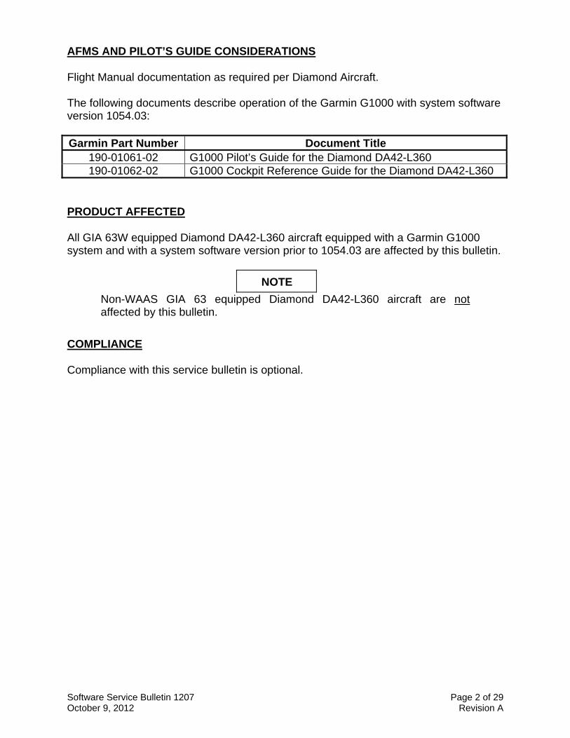
AFMS AND PILOT’S GUIDE CONSIDERATIONS Flight Manual documentation as required per Diamond Aircraft. The following documents describe operation of the Garmin G1000 with system software version 1054.03: Garmin Part Number Document Title
190-01061-02 G1000 Pilot’s Guide for the Diamond DA42-L360 190-01062-02 G1000 Cockpit Reference Guide for the Diamond DA42-L360
PRODUCT AFFECTED All GIA 63W equipped Diamond DA42-L360 aircraft equipped with a Garmin G1000 system and with a system software version prior to 1054.03 are affected by this bulletin.
NOTE
Non-WAAS GIA 63 equipped Diamond DA42-L360 aircraft are not affected by this bulletin.
COMPLIANCE Compliance with this service bulletin is optional.
Software Service Bulletin 1207 Page 3 of 29 October 9, 2012 Revision A
REFERENCES Garmin Part Number Document Title
190-00907-00 Revision E or later
Garmin G1000/G1000H System Maintenance Manual
190-01062-02 Revision A or later
Garmin G1000 Cockpit Reference Guide for the DA42-L360
190-01061-02 Revision A or later
G1000 Pilot’s Guide for the Diamond DA42-L360
The above referenced documents are available from www.garmin.com, within the Dealer Resource Center section of the website. MANPOWER This Software Service Bulletin requires a maximum of two and a half (2.5) hours labor including testing and return-to-service. WARRANTY INFORMATION This modification is not warranty reimbursable.
Software Service Bulletin 1207 Page 4 of 29 October 9, 2012 Revision A
MODIFICATION INSTRUCTIONS
1. INTRODUCTION
1.1. Scope
These instructions present field upgrade procedures for G1000-equipped Diamond Model DA42-L360 aircraft. These instructions must be followed step-by-step in order and completely to upgrade an existing approved configuration of the system software to a newer approved configuration.
It is assumed that the person performing the upgrade is familiar with the aircraft and has a working knowledge of G1000 avionics systems.
NOTE
Performing the software update described in this bulletin will delete all stored Pilot Profiles, user waypoints, stored flight plans, and map settings from memory.
Software Service Bulletin 1207 Page 5 of 29 October 9, 2012 Revision A
1.2. Software Version Identification:
To identify the installed G1000 System Software version, do the steps that follow:
1. In the aircraft, turn the aircraft Electrical Master switch on.
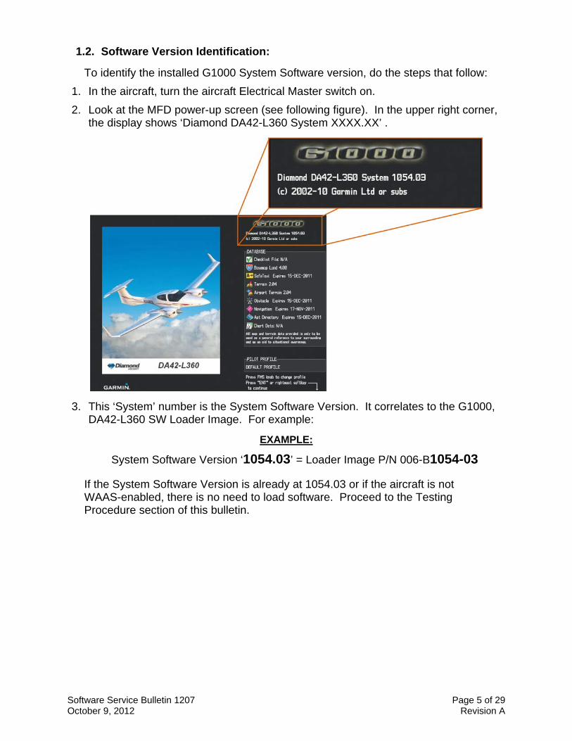
2. Look at the MFD power-up screen (see following figure). In the upper right corner, the display shows ‘Diamond DA42-L360 System XXXX.XX’ .
3. This ‘System’ number is the System Software Version. It correlates to the G1000, DA42-L360 SW Loader Image. For example:
EXAMPLE:
System Software Version ‘1054.03’ = Loader Image P/N 006-B1054-03
If the System Software Version is already at 1054.03 or if the aircraft is not WAAS-enabled, there is no need to load software. Proceed to the Testing Procedure section of this bulletin.
Software Service Bulletin 1207 Page 6 of 29 October 9, 2012 Revision A
1.3. Required Materials and Equipment:
NOTE Make sure that all of the required materials and equipment are on hand before beginning the upgrade procedure.
CAUTION While performing this procedure ensure the aircraft is connected to and drawing power from a ground power unit. A loss of power during this procedure may result in an unresponsive LRU, which may require replacement.
A ground power unit capable of supplying clean 28 VDC power to the aircraft systems and avionics.
Valid GPS Satellite signal sufficient to obtain a 3-dimensional GPS position (fix).
All items listed in the Material Information section of this bulletin.
Software Service Bulletin 1207 Page 7 of 29 October 9, 2012 Revision A
2. G1000 Software Upgrade Procedure
Turn on the G1000 system and go to the MFD AUX – SYSTEM STATUS page.
Record the 'SYSTEM ID' number here:____________________
Record the ‘SYS SOFTWARE VERSION’ here:_________________
If the SYS software Version is 1054.00, proceed to Section 2.1. If the SYS Software Version is 1054.01 or 1054.02, proceed to Section 2.2.
NOTE All G1000 screen shots used in this document are intended to provide visual reference only. All information depicted in screen shots, including software file names, versions and part numbers, is subject to change and may not be up to date.
2.1. Boot Block Update
2.1.1. Loading GDU Boot Block Version 2.03
1. Ensure the G1000 is powered off.
2. Insert the GDU Boot Block Loader Card v2.03 (see Material Information section) into the top slot of the MFD.
3. While holding the ENT key on the MFD, restore power to the MFD.
4. When the words appear in the upper left corner of the MFD, release the ENT key.
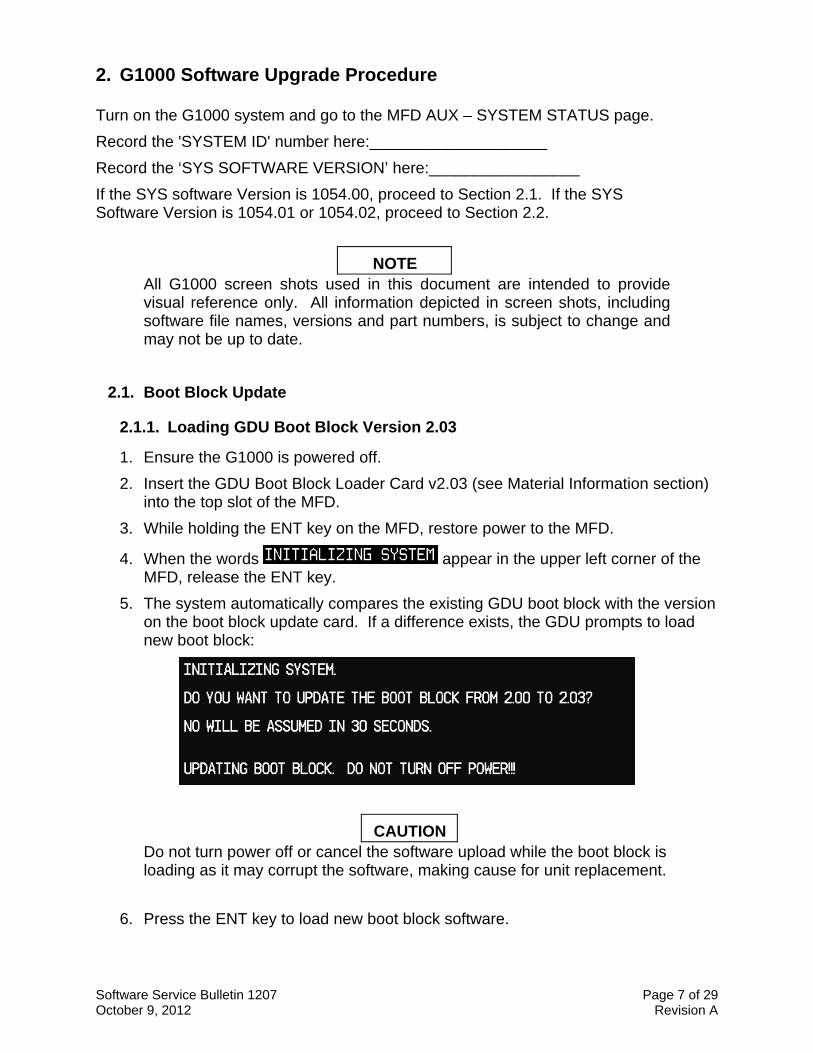
5. The system automatically compares the existing GDU boot block with the version on the boot block update card. If a difference exists, the GDU prompts to load new boot block:
CAUTION Do not turn power off or cancel the software upload while the boot block is loading as it may corrupt the software, making cause for unit replacement.
6. Press the ENT key to load new boot block software.
Software Service Bulletin 1207 Page 8 of 29 October 9, 2012 Revision A
7. When the boot block update completes and the MFD is operating in configuration mode, remove the GDU boot block update card from the MFD and insert it in the top slot of the PFD.
8. Repeat steps 3 through 6 for the PFD.
9. After the boot block is successfully loaded to the MFD and PFD, check and verify the reported boot block versions are correct by highlighting “PFD1” and “MFD1” on the System Status page.
10. When finished updating both displays, power down the G1000.
11. Remove the GDU Boot Block loader card.
12. Continue to Section 2.2.
Software Service Bulletin 1207 Page 9 of 29 October 9, 2012 Revision A
2.2. MFD and PFD Software Load
1. Remove and retain the SD terrain cards from the lower slots of the PFD and MFD, do not reinsert them until instructed to at the end of this procedure.
2. Disengage (pull) the MFD and PFD circuit breakers.
3. Turn on the ground power unit.
4. Turn on the Electrical Master switch.
5. Turn on the Avionics Master switch.
6. Insert the G1000 Software Loader Card into the MFD top card slot.
7. While holding the ENT key on the MFD, engage the MFD circuit breaker.
8. When the words appear in the upper left corner of the MFD, release the ENT key.
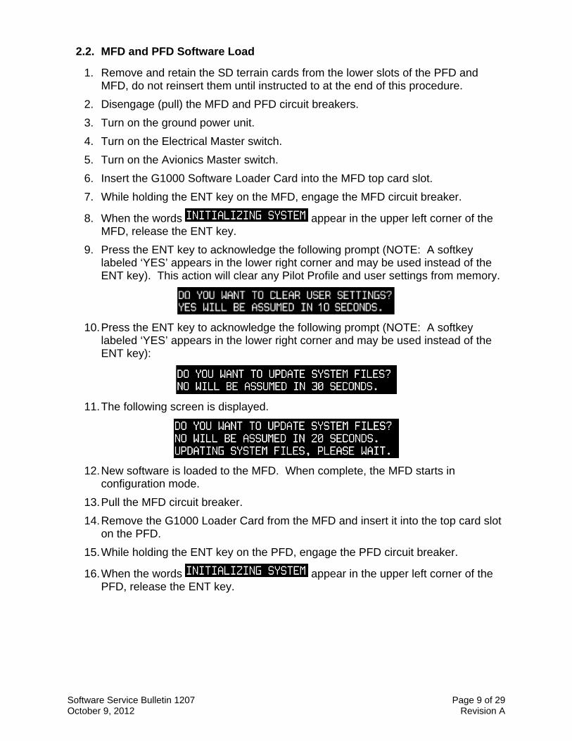
9. Press the ENT key to acknowledge the following prompt (NOTE: A softkey labeled ‘YES’ appears in the lower right corner and may be used instead of the ENT key). This action will clear any Pilot Profile and user settings from memory.
10. Press the ENT key to acknowledge the following prompt (NOTE: A softkey labeled ‘YES’ appears in the lower right corner and may be used instead of the ENT key):
11. The following screen is displayed.
12. New software is loaded to the MFD. When complete, the MFD starts in configuration mode.
13. Pull the MFD circuit breaker.
14. Remove the G1000 Loader Card from the MFD and insert it into the top card slot on the PFD.
15. While holding the ENT key on the PFD, engage the PFD circuit breaker.
16. When the words appear in the upper left corner of the PFD, release the ENT key.
Software Service Bulletin 1207 Page 10 of 29 October 9, 2012 Revision A
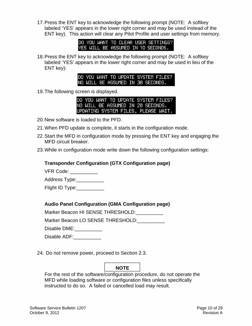
17. Press the ENT key to acknowledge the following prompt (NOTE: A softkey labeled ‘YES’ appears in the lower right corner and may be used instead of the ENT key). This action will clear any Pilot Profile and user settings from memory.
18. Press the ENT key to acknowledge the following prompt (NOTE: A softkey labeled ‘YES’ appears in the lower right corner and may be used in lieu of the ENT key):
19. The following screen is displayed.
20. New software is loaded to the PFD.
21. When PFD update is complete, it starts in the configuration mode.
22. Start the MFD in configuration mode by pressing the ENT key and engaging the MFD circuit breaker.
23. While in configuration mode write down the following configuration settings:
Transponder Configuration (GTX Configuration page)
VFR Code: __________
Address Type:__________
Flight ID Type:__________
Audio Panel Configuration (GMA Configuration page)
Marker Beacon HI SENSE THRESHOLD:__________
Marker Beacon LO SENSE THRESHOLD:__________
Disable DME:__________
Disable ADF:__________
24. Do not remove power, proceed to Section 2.3.
NOTE For the rest of the software/configuration procedure, do not operate the MFD while loading software or configuration files unless specifically instructed to do so. A failed or cancelled load may result.
Software Service Bulletin 1207 Page 11 of 29 October 9, 2012 Revision A
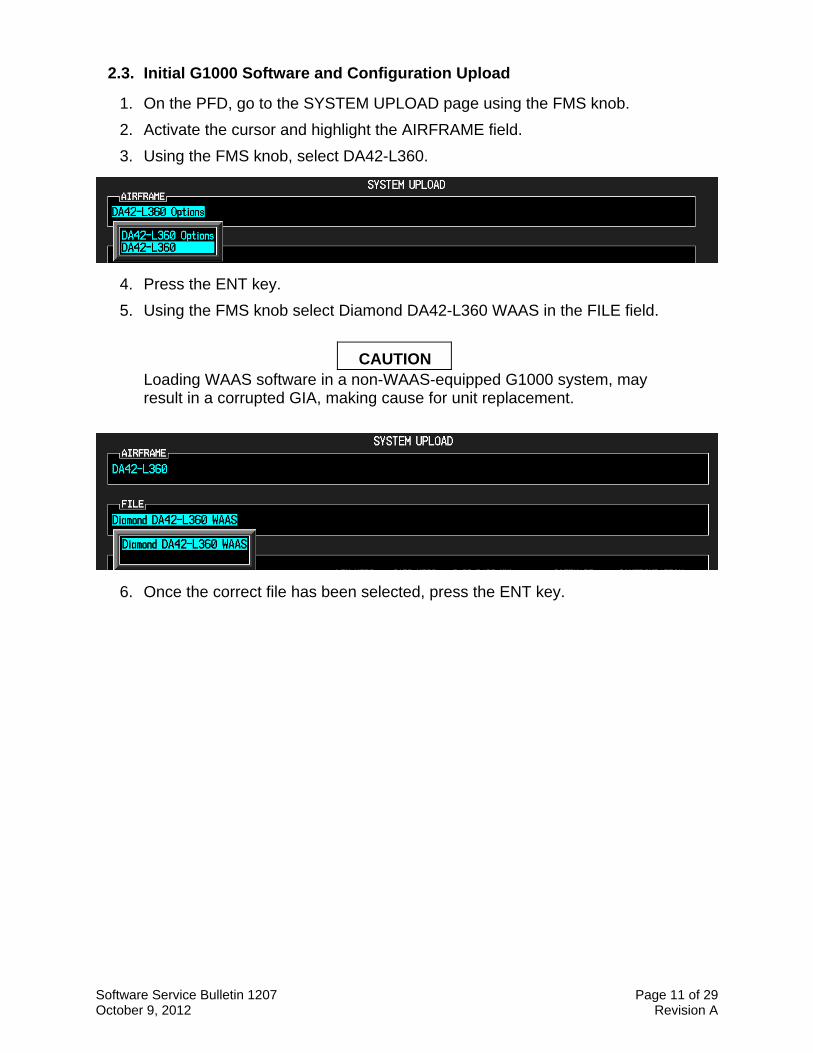
2.3. Initial G1000 Software and Configuration Upload
1. On the PFD, go to the SYSTEM UPLOAD page using the FMS knob.
2. Activate the cursor and highlight the AIRFRAME field.
3. Using the FMS knob, select DA42-L360.
4. Press the ENT key.
5. Using the FMS knob select Diamond DA42-L360 WAAS in the FILE field.
CAUTION Loading WAAS software in a non-WAAS-equipped G1000 system, may result in a corrupted GIA, making cause for unit replacement.
6. Once the correct file has been selected, press the ENT key.
Software Service Bulletin 1207 Page 12 of 29 October 9, 2012 Revision A
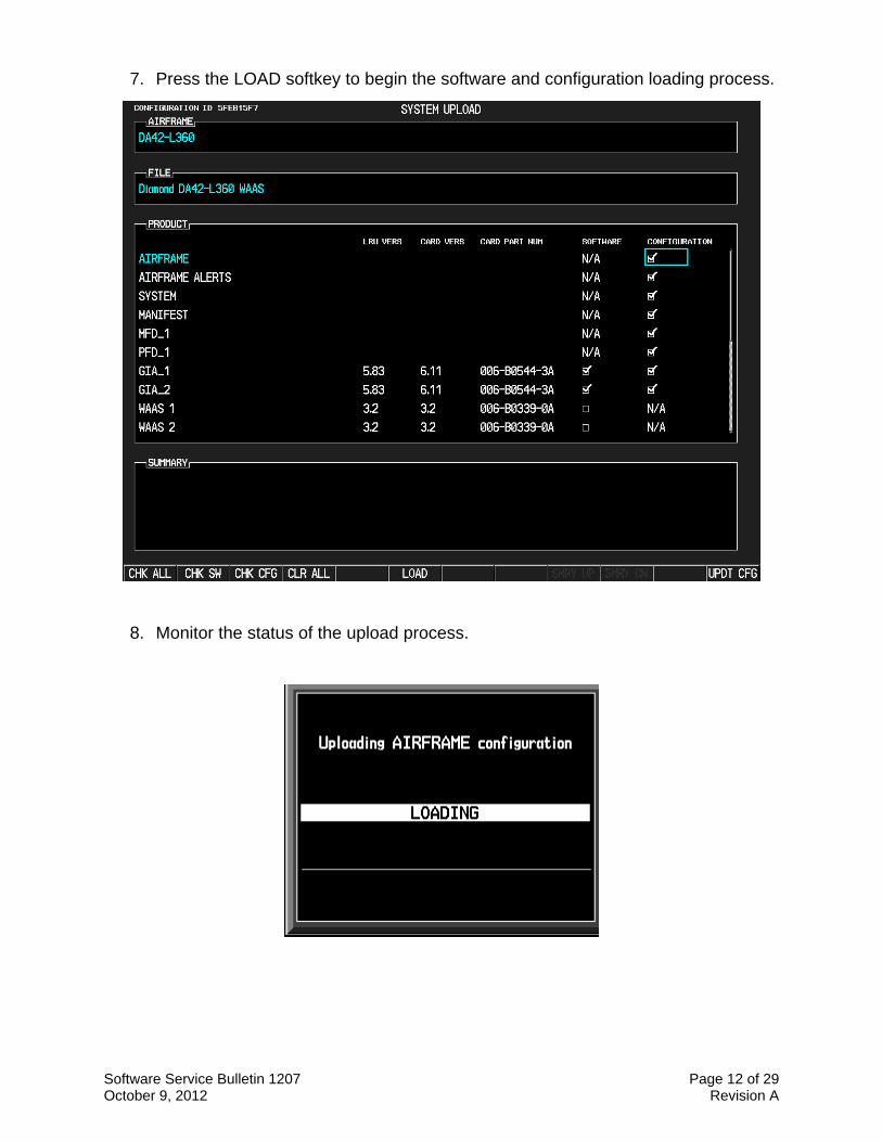
7. Press the LOAD softkey to begin the software and configuration loading process.
8. Monitor the status of the upload process.
Software Service Bulletin 1207 Page 13 of 29 October 9, 2012 Revision A
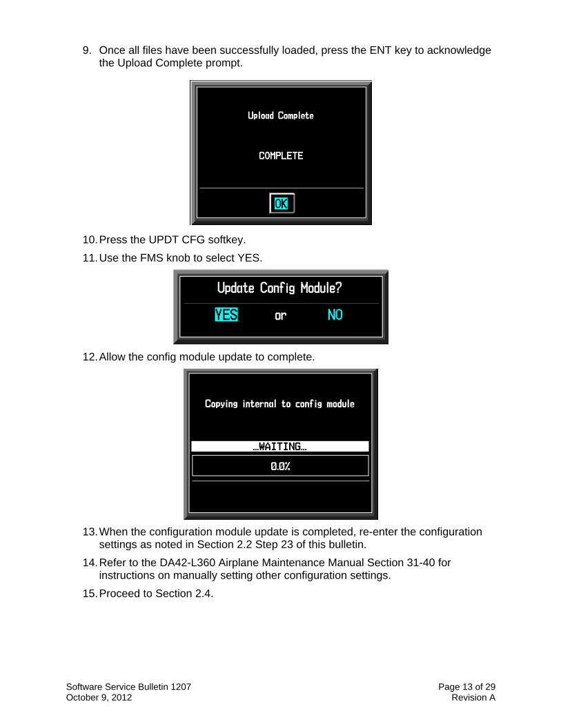
9. Once all files have been successfully loaded, press the ENT key to acknowledge the Upload Complete prompt.
10. Press the UPDT CFG softkey.
11. Use the FMS knob to select YES.
12. Allow the config module update to complete.
13. When the configuration module update is completed, re-enter the configuration settings as noted in Section 2.2 Step 23 of this bulletin.
14. Refer to the DA42-L360 Airplane Maintenance Manual Section 31-40 for instructions on manually setting other configuration settings.
15. Proceed to Section 2.4.
Software Service Bulletin 1207 Page 14 of 29 October 9, 2012 Revision A
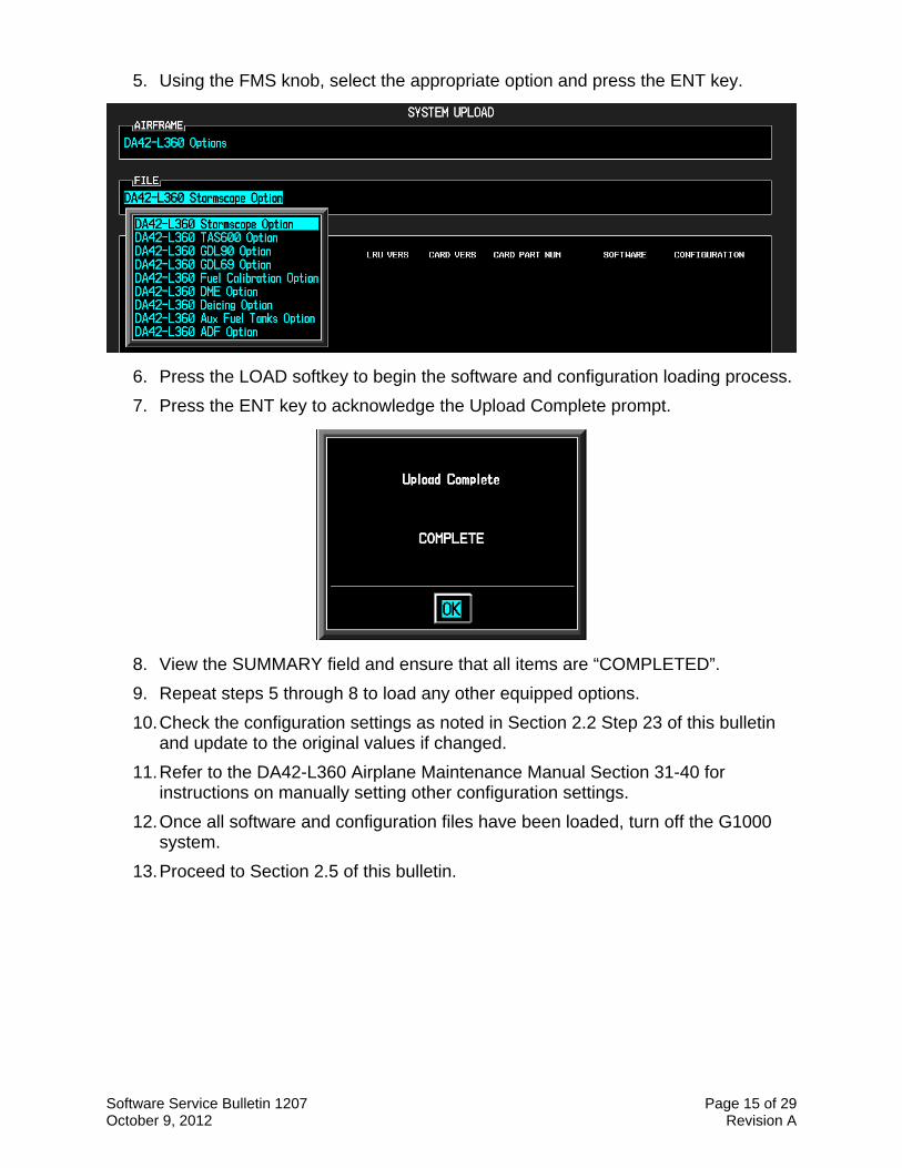
2.4. Optional Equipment
If the Diamond DA42-L360 is factory equipped with any of the following optional equipment, perform the procedure below to load software and configuration files. If the DA42-L360 is not equipped with any of the following options, proceed to Section 3 of this bulletin.
DA42-L360 – Stormscope Option
DA42-L360 – TAS600 Option
DA42-L360 – GDL90 Option
DA42-L360 – GDL69 Option
DA42-L360 – Fuel Calibration Option
DA42-L360 – DME Option
DA42-L360 – Deicing Option
DA42-L360 – Aux Fuel Tanks Option
DA42-L360 – ADF Option
NOTE
Equipment interfaced to a G1000 system that was not factory installed may require manual configuration to re-enable. Contact the installing company for information on manual configuration settings.
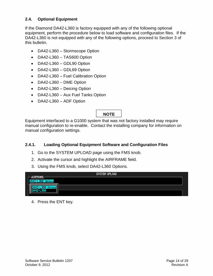
2.4.1. Loading Optional Equipment Software and Configuration Files
1. Go to the SYSTEM UPLOAD page using the FMS knob.
2. Activate the cursor and highlight the AIRFRAME field.
3. Using the FMS knob, select DA42-L360 Options.
4. Press the ENT key.
Software Service Bulletin 1207 Page 15 of 29 October 9, 2012 Revision A
5. Using the FMS knob, select the appropriate option and press the ENT key.
6. Press the LOAD softkey to begin the software and configuration loading process.
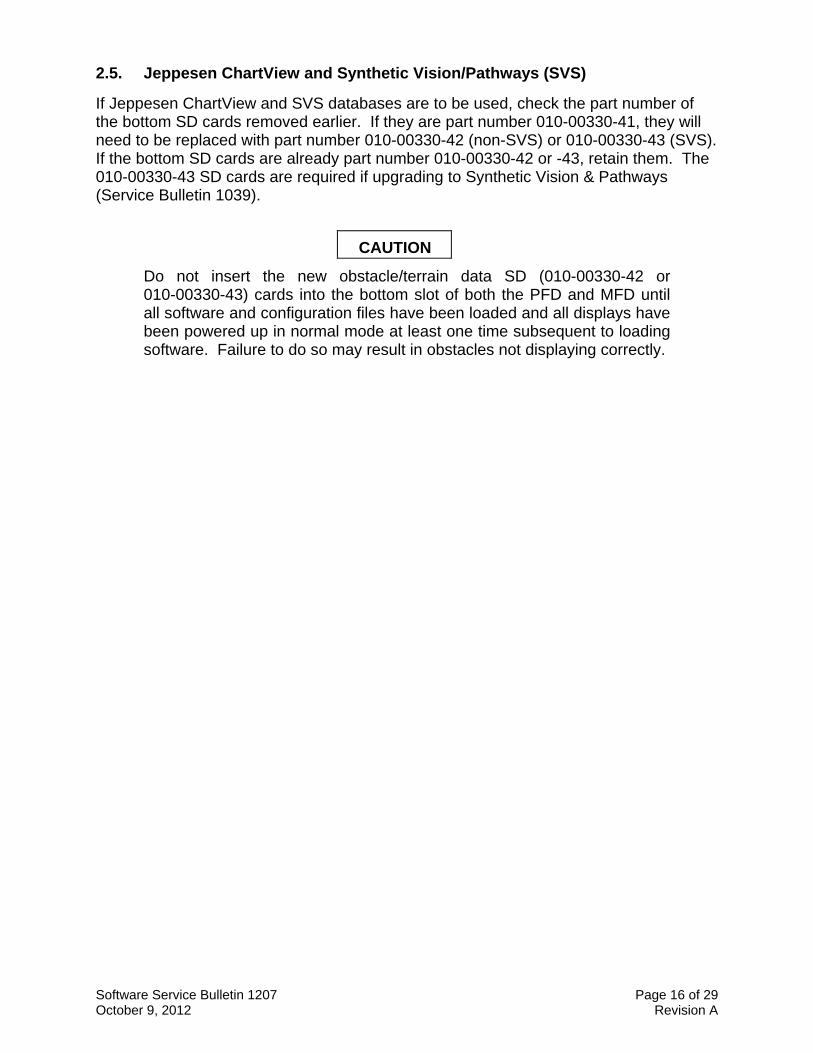
7. Press the ENT key to acknowledge the Upload Complete prompt.
8. View the SUMMARY field and ensure that all items are “COMPLETED”.
9. Repeat steps 5 through 8 to load any other equipped options.
10. Check the configuration settings as noted in Section 2.2 Step 23 of this bulletin and update to the original values if changed.
11. Refer to the DA42-L360 Airplane Maintenance Manual Section 31-40 for instructions on manually setting other configuration settings.
12. Once all software and configuration files have been loaded, turn off the G1000 system.
13. Proceed to Section 2.5 of this bulletin.
Software Service Bulletin 1207 Page 16 of 29 October 9, 2012 Revision A
2.5. Jeppesen ChartView and Synthetic Vision/Pathways (SVS)
If Jeppesen ChartView and SVS databases are to be used, check the part number of the bottom SD cards removed earlier. If they are part number 010-00330-41, they will need to be replaced with part number 010-00330-42 (non-SVS) or 010-00330-43 (SVS). If the bottom SD cards are already part number 010-00330-42 or -43, retain them. The 010-00330-43 SD cards are required if upgrading to Synthetic Vision & Pathways (Service Bulletin 1039).
CAUTION
Do not insert the new obstacle/terrain data SD (010-00330-42 or 010-00330-43) cards into the bottom slot of both the PFD and MFD until all software and configuration files have been loaded and all displays have been powered up in normal mode at least one time subsequent to loading software. Failure to do so may result in obstacles not displaying correctly.

Software Service Bulletin 1207 Page 17 of 29 October 9, 2012 Revision A
2.5.1. Jeppesen ChartView Unlock
NOTE
When the ChartView option is enabled for the first time, the G1000 writes its unique System ID to the card and locks it to the aircraft. That same card must be used to re-activate ChartView for this software update.
NOTE
If the unlock card does not work, the software update may have caused the system ID to change. Compare the current System ID number to the one recorded in Section 2 of this procedure. If the number has changed, contact Garmin Product Support to replace the unlock card.
1. Remove power from the PFD and MFD.
2. Insert the Jeppesen ChartView Unlock Card (010-00330-50) in the upper slot of the PFD.
3. While holding the ENT key on the PFD and MFD, restore power to both displays.
4. When the words appear in the upper left corner of the displays, release the ENT key.
5. On the PFD, go to the System Upload page using the FMS knob.
6. Activate the cursor and use the FMS knob to select CONFIGURATION FILES in the AIRFRAME field and press the ENT key.
7. Highlight the FILE field and use the FMS knob to select the ENABLE CHARTVIEW option and press the ENT key. Once the option is selected the configuration files in the PRODUCT field will be displayed. All files should be checked. If not, press the CHK ALL softkey.
8. Press the LOAD softkey.
9. Monitor the status of the upload. When the upload is finished, press the ENT key to acknowledge the upload complete confirmation.
10. View the SUMMARY field and ensure the item is COMPLETE.
11. Deactivate the cursor.
12. Turn off the G1000 system.
13. Remove the ChartView Unlock Card from the PFD.
Software Service Bulletin 1207 Page 18 of 29 October 9, 2012 Revision A
2.5.2. SVS Activation
1. Remove power from the PFD and MFD.
2. Ensure the 010-00330-43 terrain data card has been removed from the bottom card slot of the MFD and PFD.
3. Turn on the ground power unit, if used.
4. Turn on the Electrical Master Switch.
5. Turn on the Avionics Master switch. At this moment, all G1000 equipment should be receiving power, except the PFD and MFD.
6. Insert the Synthetic Vision & Pathways unlock card (010-00330-54) in the upper slot of the PFD.
7. While holding the ENT key on the MFD, restore power by closing the MFD circuit breaker.
8. When the words appear in the upper left corner of the MFD, release the ENT key.
9. Repeat Steps 7 and 8 for the PFD.
10. On the PFD, go to the System Upload page using the FMS knob.
11. Activate the cursor.
12. Use the small FMS knob to select “CONFIGURATION FILES” in the AIRFRAME field.
13. Press the ENT key.
14. Use the small FMS knob to select the “Enable SVS Single PFD” option in the FILE field.
15. Press the ENT key.
16. Once the option is selected the configuration files in the PRODUCT field will be displayed. All files should be checked. If not, press the CHK ALL softkey.
17. Press the LOAD softkey.
18. Monitor the status of the upload. When the upload is finished, press the ENT key to acknowledge the upload complete confirmation.
19. View the SUMMARY field and ensure that the item is ‘COMPLETED’.
20. Power down the system and remove the SVS Unlock card from the PFD.
21. Insert the 010-00330-43 terrain cards into the bottom card slot of the PFD and MFD.
Software Service Bulletin 1207 Page 19 of 29 October 9, 2012 Revision A
3. TESTING PROCEDURE
3.1. Software Operational Test
The G1000 system is tested while operating in the normal mode.
1. Turn off the G1000 system.
2. Remove the G1000 Software Loader and/or Unlock cards from the top slot of the PFD.
3. Turn on the G1000 system and acknowledge any displayed messages regarding verifying the databases.
4. After both displays have powered up, turn off the G1000 system (this sets the system ID’s).
5. Insert the SD terrain cards in the bottom slots of the displays.
6. Turn on the G1000 system, and acknowledge any displayed messages regarding verifying the databases.
NOTE
If the system start up messages indicate the Terrain, Obstacle, and other databases are not valid for this System (Section 2.5.1), contact Garmin Product Support for information regarding how to replace or reload the Garmin database cards. If the System ID number has changed, the Jeppesen Navigation Database and ChartView database may also need to be reloaded; contact Jeppesen Product Support for assistance in updating the new System ID on the owner's account and obtaining a new download.
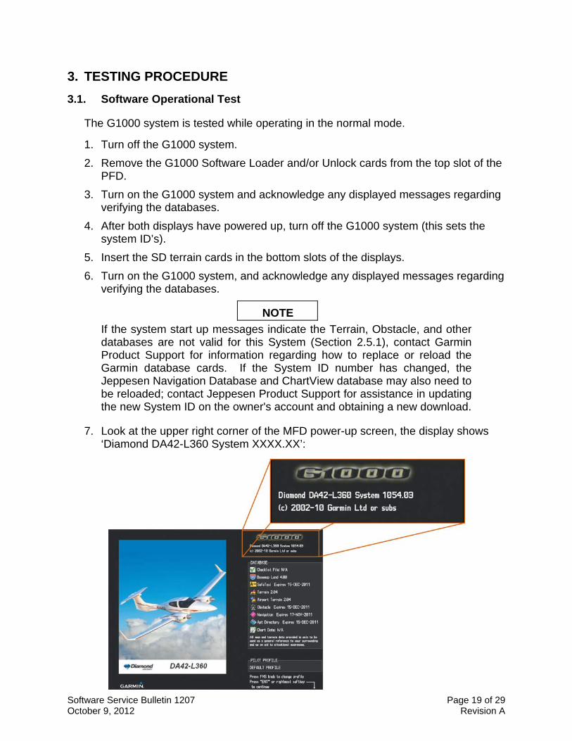
7. Look at the upper right corner of the MFD power-up screen, the display shows ‘Diamond DA42-L360 System XXXX.XX’:
Software Service Bulletin 1207 Page 20 of 29 October 9, 2012 Revision A
8. This ‘System’ number is the System Software Version. It correlates to the G1000 SW Loader Image used to load the software to the system:
EXAMPLE:
System Software Version ‘1054.03’ = Loader Image P/N 006-B1054-03
9. Verify that the displayed System Software Version is 1054.03.
10. Press the ENT key to acknowledge the agreement on the MFD (the rightmost softkey may also be used to acknowledge the agreement).
NOTE In the normal operating mode, data fields that are invalid have large red X’s through them. A valid field does not display a red X.
11. Allow the displays to initialize for approximately one minute. The GDC 74A and GRS 77/GMU 44 require a longer initialization period than do other LRUs. During normal operation, this causes the attitude, heading, airspeed, altitude, vertical speed, and OAT fields to be invalid during the first 40-60 seconds of PFD power-up.
NOTE Make sure that the aircraft remains stationary during the initialization. Any movement such as wind buffeting or climbing in/out of the aircraft may cause the attitude to Red-X or prolong the initialization.
12. Verify that no ‘Manifest’ or ‘Config’ errors appear when the ALERTS softkey is pressed.
13. Check that all COM/NAV fields are valid in the top corners of the PFD and MFD.
14. Check that attitude, heading, altitude, airspeed, vertical speed, TAS, and OAT fields are valid on the PFD.
15. Verify that there are no BACKUP PATH alerts on the PFD. If an LRU is not communicating over its primary path, the BACKUP PATH alert will identify which LRU is having the problem. Correct the problem before proceeding; refer to the G1000 System Maintenance Manual (190-00907-00) as needed.
16. Verify that engine and airframe instruments are valid on the MFD.
17. Push the red DISPLAY BACKUP button on the GMA 1347. Verify both displays enter reversion mode: both should have valid attitude, altitude, airspeed, vertical speed, and engine instruments.
Software Service Bulletin 1207 Page 21 of 29 October 9, 2012 Revision A
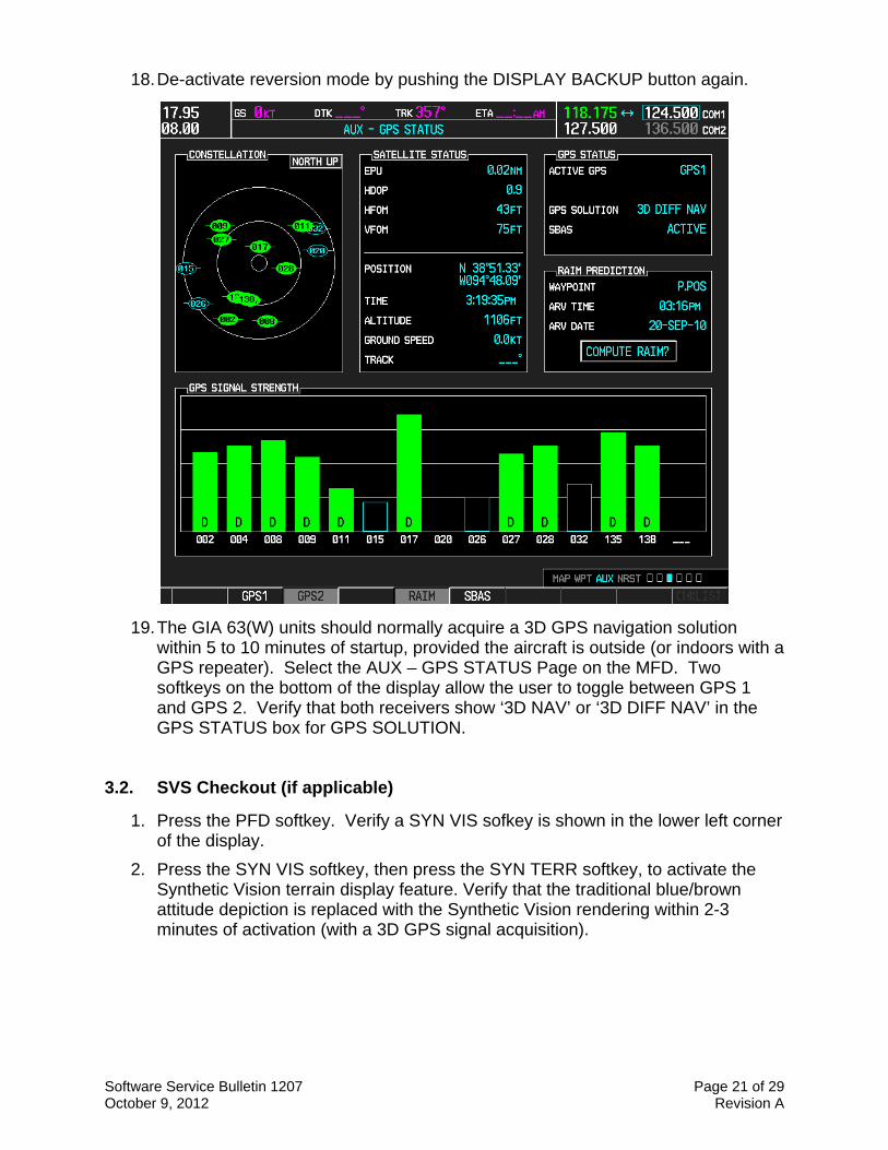
18. De-activate reversion mode by pushing the DISPLAY BACKUP button again.
19. The GIA 63(W) units should normally acquire a 3D GPS navigation solution within 5 to 10 minutes of startup, provided the aircraft is outside (or indoors with a GPS repeater). Select the AUX – GPS STATUS Page on the MFD. Two softkeys on the bottom of the display allow the user to toggle between GPS 1 and GPS 2. Verify that both receivers show ‘3D NAV’ or ‘3D DIFF NAV’ in the GPS STATUS box for GPS SOLUTION.
3.2. SVS Checkout (if applicable)
1. Press the PFD softkey. Verify a SYN VIS sofkey is shown in the lower left corner of the display.
2. Press the SYN VIS softkey, then press the SYN TERR softkey, to activate the Synthetic Vision terrain display feature. Verify that the traditional blue/brown attitude depiction is replaced with the Synthetic Vision rendering within 2-3 minutes of activation (with a 3D GPS signal acquisition).
Software Service Bulletin 1207 Page 22 of 29 October 9, 2012 Revision A
3.3. ADF Checkout (if applicable)
This check verifies that the ADF-to-G1000 interface operates correctly. This check is required for DA42-L360 aircraft with the remote-mount Becker RA3502 ADF installed.
1. On the PFD, check to see if the ADF window(s) is displayed. If not, press the PFD softkey. Using either the BRG1 or BRG2 softkeys, toggle the softkey until the ADF bearing is shown. Press the BACK softkey.
2. Verify that the ADF window is not invalid (no red ‘X’).
3. Press the ADF/DME softkey and check to ensure the ADF tuning window displays correctly.
3.4. DME Checkout (if applicable)
This check verifies that the DME-to-G1000 interface operates correctly. This check is required for DA42-L360 aircraft with the Honeywell remote mounted KN63 DME installed.
1. On the PFD, check to see if the DME window is displayed. If not, press the PFD softkey, then press the DME softkey to display the DME window next to the HSI.
2. Verify that the DME window is not invalid (no red ‘X’).
3. On the PFD, press the ADF/DME softkey. Verify that the ADF/DME TUNING screen is displayed correctly.
Software Service Bulletin 1207 Page 23 of 29 October 9, 2012 Revision A
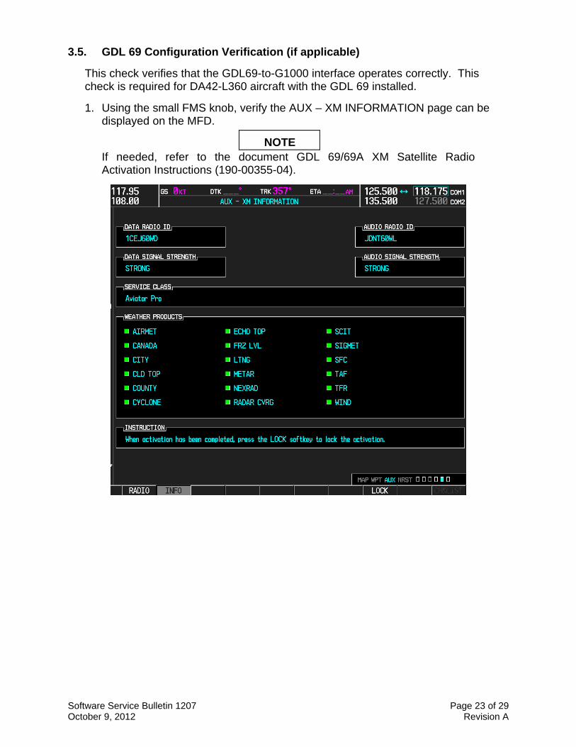
3.5. GDL 69 Configuration Verification (if applicable)
This check verifies that the GDL69-to-G1000 interface operates correctly. This check is required for DA42-L360 aircraft with the GDL 69 installed.
1. Using the small FMS knob, verify the AUX – XM INFORMATION page can be displayed on the MFD.
NOTE If needed, refer to the document GDL 69/69A XM Satellite Radio Activation Instructions (190-00355-04).
Software Service Bulletin 1207 Page 24 of 29 October 9, 2012 Revision A
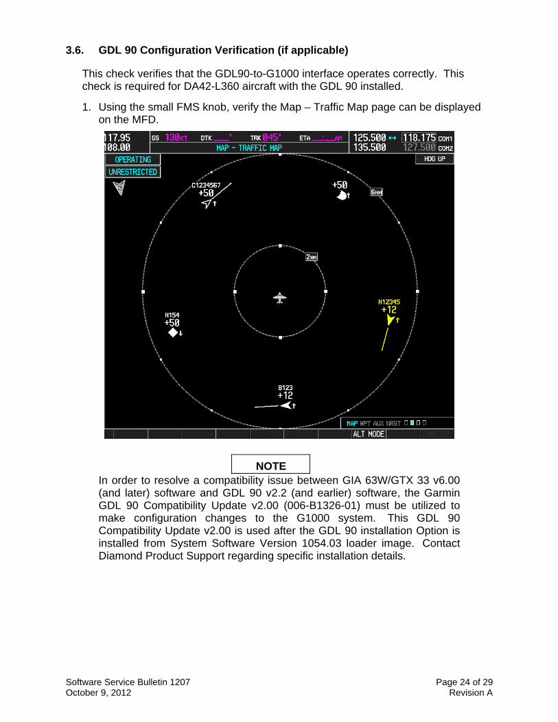
3.6. GDL 90 Configuration Verification (if applicable)
This check verifies that the GDL90-to-G1000 interface operates correctly. This check is required for DA42-L360 aircraft with the GDL 90 installed.
1. Using the small FMS knob, verify the Map – Traffic Map page can be displayed on the MFD.
NOTE In order to resolve a compatibility issue between GIA 63W/GTX 33 v6.00 (and later) software and GDL 90 v2.2 (and earlier) software, the Garmin GDL 90 Compatibility Update v2.00 (006-B1326-01) must be utilized to make configuration changes to the G1000 system. This GDL 90 Compatibility Update v2.00 is used after the GDL 90 installation Option is installed from System Software Version 1054.03 loader image. Contact Diamond Product Support regarding specific installation details.

Software Service Bulletin 1207 Page 25 of 29 October 9, 2012 Revision A
3.7. Stormscope Configuration Verification (if applicable)
This check verifies that the L-3 Communications Stormscope interface operates correctly. This check is required for DA42-L360 aircraft with the Stormscope installed.
1. Using the small FMS knob, verify the Map – Stormscope page can be displayed on the MFD.
Software Service Bulletin 1207 Page 26 of 29 October 9, 2012 Revision A
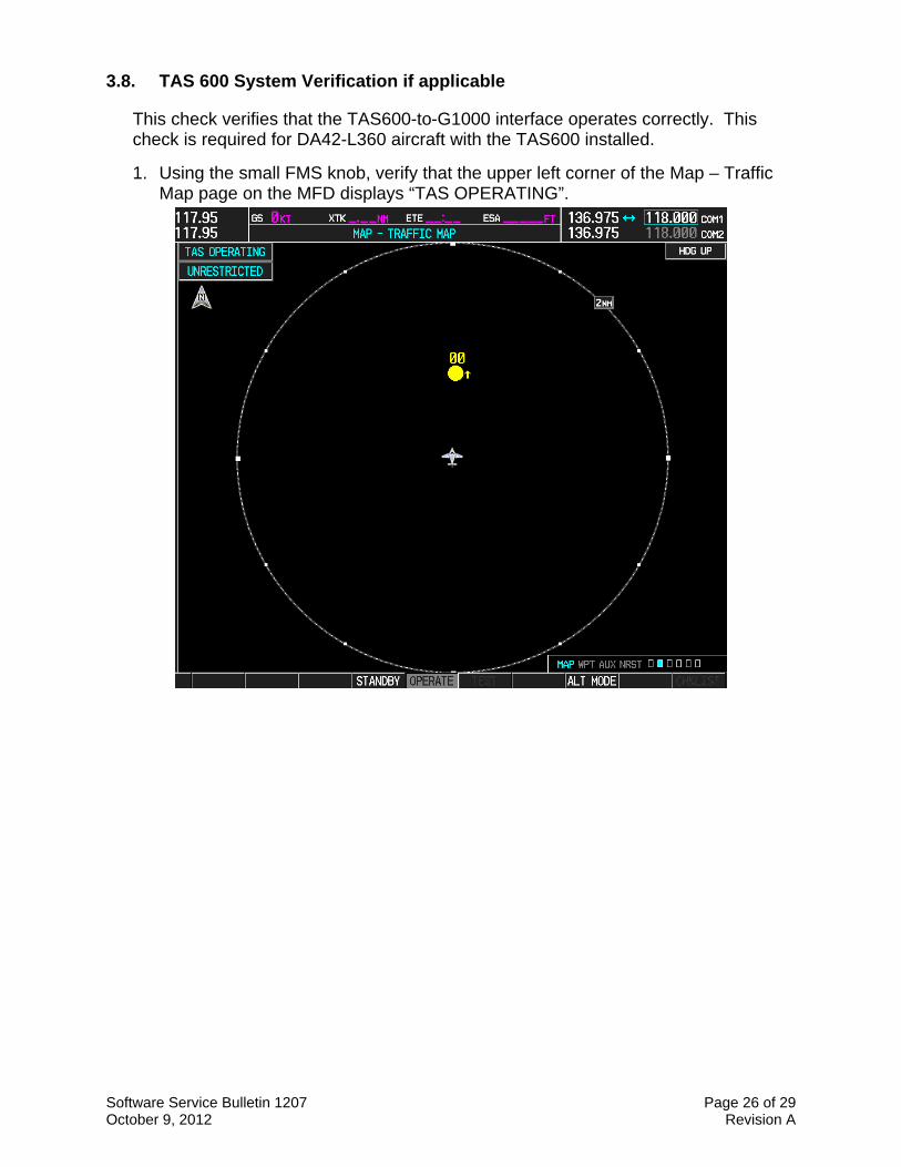
3.8. TAS 600 System Verification if applicable
This check verifies that the TAS600-to-G1000 interface operates correctly. This check is required for DA42-L360 aircraft with the TAS600 installed.
1. Using the small FMS knob, verify that the upper left corner of the Map – Traffic Map page on the MFD displays “TAS OPERATING”.
Software Service Bulletin 1207 Page 27 of 29 October 9, 2012 Revision A
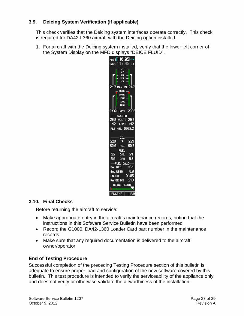
3.9. Deicing System Verification (if applicable)
This check verifies that the Deicing system interfaces operate correctly. This check is required for DA42-L360 aircraft with the Deicing option installed.
1. For aircraft with the Deicing system installed, verify that the lower left corner of the System Display on the MFD displays ”DEICE FLUID”.
3.10. Final Checks
Before returning the aircraft to service:
Make appropriate entry in the aircraft’s maintenance records, noting that the instructions in this Software Service Bulletin have been performed
Record the G1000, DA42-L360 Loader Card part number in the maintenance records
Make sure that any required documentation is delivered to the aircraft owner/operator
End of Testing Procedure Successful completion of the preceding Testing Procedure section of this bulletin is adequate to ensure proper load and configuration of the new software covered by this bulletin. This test procedure is intended to verify the serviceability of the appliance only and does not verify or otherwise validate the airworthiness of the installation.
Software Service Bulletin 1207 Page 28 of 29 October 9, 2012 Revision A
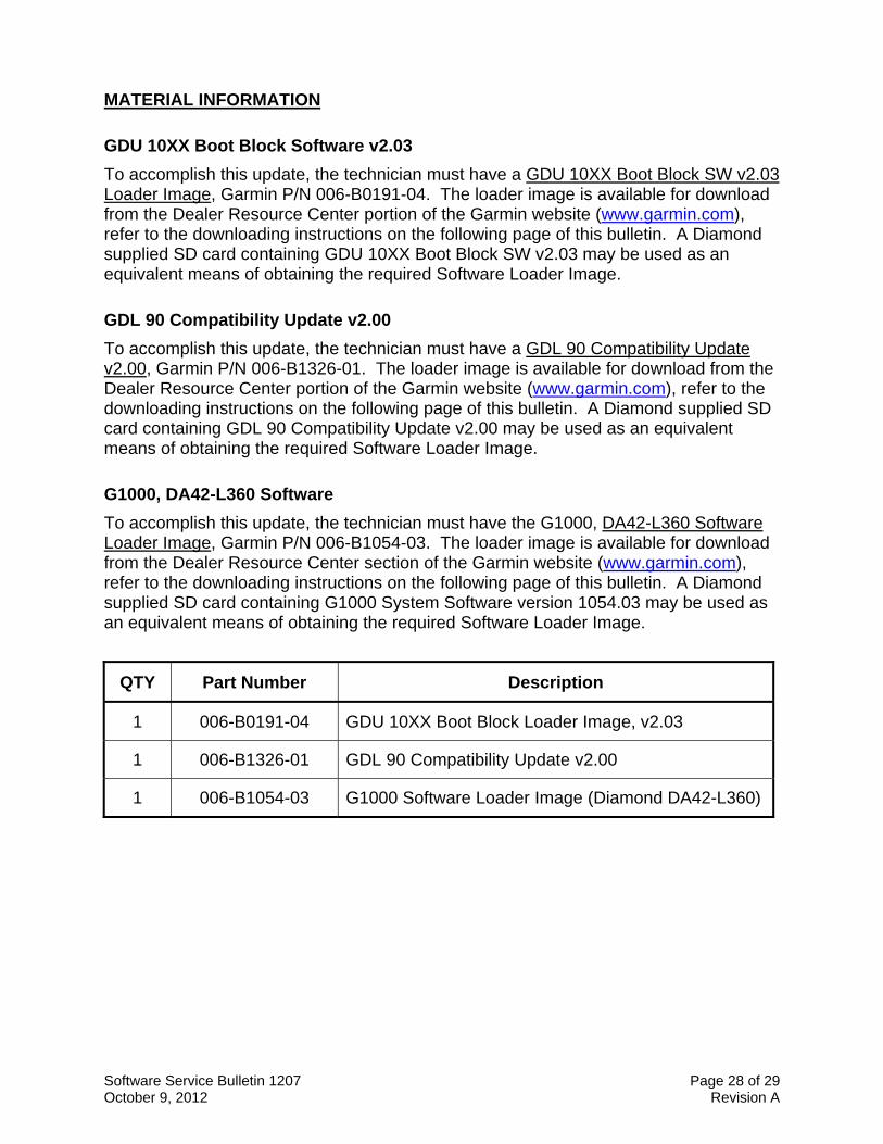
MATERIAL INFORMATION
GDU 10XX Boot Block Software v2.03
To accomplish this update, the technician must have a GDU 10XX Boot Block SW v2.03 Loader Image, Garmin P/N 006-B0191-04. The loader image is available for download from the Dealer Resource Center portion of the Garmin website (www.garmin.com), refer to the downloading instructions on the following page of this bulletin. A Diamond supplied SD card containing GDU 10XX Boot Block SW v2.03 may be used as an equivalent means of obtaining the required Software Loader Image.
GDL 90 Compatibility Update v2.00
To accomplish this update, the technician must have a GDL 90 Compatibility Update v2.00, Garmin P/N 006-B1326-01. The loader image is available for download from the Dealer Resource Center portion of the Garmin website (www.garmin.com), refer to the downloading instructions on the following page of this bulletin. A Diamond supplied SD card containing GDL 90 Compatibility Update v2.00 may be used as an equivalent means of obtaining the required Software Loader Image.
G1000, DA42-L360 Software
To accomplish this update, the technician must have the G1000, DA42-L360 Software Loader Image, Garmin P/N 006-B1054-03. The loader image is available for download from the Dealer Resource Center section of the Garmin website (www.garmin.com), refer to the downloading instructions on the following page of this bulletin. A Diamond supplied SD card containing G1000 System Software version 1054.03 may be used as an equivalent means of obtaining the required Software Loader Image.
QTY Part Number Description
1 006-B0191-04 GDU 10XX Boot Block Loader Image, v2.03
1 006-B1326-01 GDL 90 Compatibility Update v2.00
1 006-B1054-03 G1000 Software Loader Image (Diamond DA42-L360)
Software Service Bulletin 1207 Page 29 of 29 October 9, 2012 Revision A
GDU Boot Block and G1000 Software Loader Image Download Instructions
1. From the Dealer Resource portion of the Garmin website (www.garmin.com), follow the instructions to download the file to the computer. It is recommended to create a folder ‘C:/Garmin’ as a target directory for the file. Do NOT save the download file to a SD card. The downloaded file will need to be run to create the G1000 software loader card.
2. Insert a blank SD card into the PC SD card reader. If the card needs to be formatted, format it in the FAT32 format. Recommended size for the card is 128MB-2GB.
3. Run the downloaded file from Step 1 on the PC and follow the on-screen instructions to make the G1000 software loader card.
4. When the program is complete, remove the SD card from the PC SD card reader. It is ready to use in a G1000 system. It may also be used in multiple aircraft as the number of uses is unrestricted.
ADDITIONAL INFORMATION Garmin recommends that the installer and owner/operator review the service documents listed at www.garmin.com for applicable Service Alerts and Service Advisories relevant to the software installed by this bulletin. To aid in finding service documents applicable to this software upgrade, unit software versions affected by this service bulletin are as follows:
GDU main software version 11.13 GIA 63W main software version 6.11 GRS 77 main software version 3.02 GDC 74A main software version 3.08 GDL 69A main software version 4.01
For information regarding new software features, Garmin recommends downloading a free copy of the DA42-L360 G1000 Pilot's Guide P/N 190-01061-02 from Garmin’s website at www.garmin.com.