Embed Size (px)
Citation preview

PROPOSAL
D263505F.A. PROJECT
Book 3 of 8
Submitted in accordance with the Highway Law and the Standard Specifications officially finalized and adopted on September 1, 2017 as posted on the Department's website.
US CUSTOMARY UNITS
Proposal Description:
Schenectady Rail Station Building Project in the City of Schenectady.
Letting of 10/5/2017 @ 10:30 A.M.
50 Wolf Road, Albany, NY 12232

00775 Page 1 of 1 L09/03/09
THIS PAGE INTENTIONALLY LEFT BLANK
D263505

Special Note 5 – Building Erection, Construction or Alteration
The proposed project includes specialty work for the construction of a new Schenectady Station Building, as
noted below and as noted on the plans. Payment for all labor, equipment, and materials necessary for the
work shown in the plans and contract documents will be made under the following item:
Under Item No. 622.01010001 - Building Erection, Construction or Alteration, the Contractor
shall furnish all labor, materials and equipment for completion of Work.
The Contractor’s application for payment will be submitted on the following documents: AIA Document G702
and Continuation Sheet AIA Document G703. Sample copies are provided within the construction documents.
The contractor’s attention is directed to the fact that some of the technical and material specifications associated
with the specialty work items may contain proprietary references. The intent of these proprietary references is
not to limit selection of products and/or suppliers, but rather to provide one or more "benchmark" products to
serve as a basis for the bid. For these products, the contractor may propose the use of an "equal" product
through the standard Shop Drawing / Product Data / Sample submittal process, including written justification
to demonstrate product equivalence for Owner’s review. Owner will determine if proposed submittal is an
acceptable / unacceptable equivalent substitution.
The following are the technical specifications for the specialty work paid under 622.01010001:
TABLE OF CONTENTS
DIVISION 01 – GENERAL REQUIREMENTS
010000 General Notes
011000 Summary
013000 Submittals
013100 Project Management and Coordination
013200 Construction Progress Documentation
013300 Submittal Procedures
014100 Special Inspections and Structural Testing
014100a Statement of Special Inspections
014100b Schedule of Special Inspection Services
014100c Final Report of Special Inspections
014200 References
014210 Reference Standards and Definitions
015000 Temporary Facilities and Controls
017400 Warranties
017700 Closeout Procedures
017823 Operation and Maintenance Data
017839 Project Record Documents
DIVISION 02 – EXISTING CONDITIONS
024119 Selective Demolition
183D263505
DIVISION 03 – CONCRETE
033000 Cast-in-Place Concrete – Station Building
034500 Precast Architectural Concrete
DIVISION 04 – MASONRY
042000 Unit Masonry
044313.13 Anchored Stone Masonry Veneer
047200 Cast Stone Masonry
DIVISION 05 – METALS
051200 Structural Steel Framing - Buildings & Canopies
053100 Steel Decking – Station Building
053200 Steel Decking – Platform Canopy & Headhouse
055000 Metal Fabrications
055113 Metal Pan Stair
055213 Pipe and Tube Railings
DIVISION 06 – WOOD, PLASTICS, AND COMPOSITES
061000 Rough Carpentry
061053 Miscellaneous Rough Carpentry
064116 Plastic-Laminate Faced Architectural Cabinets
064600 Wood Trim
066400 Plastic Paneling
DIVISION 07 – THERMAL AND MOISTURE PROTECTION
071616 Crystalline Waterproofing
072100 Thermal Insulation
072413 Direct Applied Exterior Finish System (DEFS)
074113.16 Standing-Seam Metal Panel roofing
074213.23 Metal Composite Material Wall Panels
075323 Ethylene-Propylene-Diene-Monomer (EPDM) Roofing
076100 Sheet Metal Roofing
076200 Sheet Metal Flashing and Trim
077100 Roof Specialties
077200 Roof Accessories
078413 Penetration Firestopping
078446 Fire Resistive Joint Systems
079200 Joint Sealants
079500 Expansion Control
DIVISION 08 – OPENINGS
081113 Hollow Metal Doors and Frames
081119 Stainless-Steel Doors and Frames
184 D263505

081416 Flush Wood Doors
083113 Access Doors and Frames
083323 Overhead Coiling Doors
084113 Aluminum-Framed Entrances and Storefronts
084226 All-Glass Entrances
084423 Fire-Rated Glazed Steel Curtain Wall
084513 Structured-Polycarbonate-Panel Assemblies
087100 Door Hardware
088000 Glazing
089000 Louvers and Vents
DIVISION 09 – FINISHES
092216 Non-Structural Metal Framing
092713 Glass-Fiber-Reinforced Plaster Fabrications
092900 Gypsum Board
093000 Tiling
095133 Acoustical Metal Panel Ceilings
095444 Modular Metal Ceiling System
096513 Resilient Base and Accessories
096536 Static-Control Resilient Flooring
096623 Resinous Matrix Terrazzo Flooring
096723 Resinous Flooring
096813 Tile Carpeting
097713 Stretched-Fabric Wall Systems
099123 Interior Painting
099600 High-Performance Coatings
099750 Sanitary Wall Panels (FRP)
DIVISION 10 – SPECIALTIES
101400 Signage
101419 Dimensional Letter Signage
101423 Traffic Signs
102113 Toilet Compartments
102800 Toilet, Bath and Laundry Accessories
104413 Fire Protection Cabinets
104416 Fire Extinguishers
109990 Miscellaneous Specialties
185D263505

DIVISION 12 – FURNISHINGS
123661 Simulated Stone
126100 Fixed Audience Seating
129323 Trash and Recycling Receptors
DIVISION 14 – CONVEYING EQUIPMENT
142400 Machine Room-Less Hydraulic Elevators
DIVISION 21 – FIRE SUPPRESSION
210517 Sleeves and Sleeve Seals for Fire-Suppression Piping
210518 Escutcheons for Fire-Suppression Piping
210553 Identification for Fire-Suppression Piping and Equipment
211313 Wet-Pipe Sprinkler Systems
211316 Dry-Pipe Sprinkler Systems
DIVISION 22 – PLUMBING
220513 Common Motor Requirements for Plumbing Equipment
220517 Sleeves and Sleeve Seals for Plumbing Piping
220518 Escutcheons for Plumbing Piping
220519 Meters and Gages for Plumbing Piping
220523 General-Duty Valves for Plumbing Piping
220529 Hangers and Supports
220553 Mechanical Identification
220700 Pipe Insulation
221116 Domestic Water Piping
221116 Ductile Iron Water Main Pipe & Fittings
221117 Tapping Sleeve & Gate Valve
221118 Testing Water Mains
221119 Disinfection of Water Main
221120 Domestic Water Piping Specialties
221123 Domestic Water Pumps
221128 Facility Natural-Gas Piping
221313 Sanitary Sewer Lateral
221316 Sanitary Waste and Vent Piping
221319 Sanitary Waste Piping Specialties
221413 Storm Drainage
221414 Facility Storm Drainage Piping
221423 Storm Drainage Piping Specialties
221429 Sump Pumps
223400 Fuel-Fired, Domestic-Water Heaters
224213.13 Commercial Water Closets
224213.16 Commercial Urinals
224216.13 Commercial Lavatories
186 D263505

DIVISION 22 – PLUMBING (CONTINUED)
224216.16 Commercial Sinks
224716 Pressure Water Coolers
DIVISION 23 – HEATING VENTILATING AND AIR CONDITIONING
230010 General Mechanical Requirements
230513 Common Motor Requirements for HVAC Equipment
230517 Sleeves and Sleeve Seals for HVAC Piping
230518 Escutcheons for HVAC Piping
230519 Meters and Gages for HVAC Piping
230523 General-Duty Valves for HVAC Piping
230529 Hangers and Supports for HVAC Piping and Equipment
230548 Vibration and Seismic Controls for HVAC Piping and Equipment
230553 Identification for HVAC Piping and Equipment
230593 Testing, Adjusting, and Balancing for HVAC
230713 Duct Insulation
230719 HVAC Piping Insulation
230900 Instrumentation and Controls for HVAC
230993 Sequence of Operation for HVAC Controls
232113 Hydronic Piping
232116 Hydronic Piping Specialties
232123 Hydronic Pumps
232300 Refrigerant Piping
232500 HVAC Water Treatment
232923 Variable Frequency Motor Controllers
233113 Metal Ducts
233300 Air Duct Accessories
233423 HVAC Power Ventilators
233600 Air Terminal Units
233713 Diffusers, Registers, and Grilles
235100 Breechings, Chimneys, and Stacks
235216 Boilers
237313 Indoor Central-Station Air-Handling Units
238123 Computer-Room Air-Conditioners
238229 Radiators
238239 Unit Heaters
DIVISION 26 – ELECTRICAL
260500 Common Work Results for Electrical
260519 Low-Voltage Electrical Power Conductors and Cables
260526 Grounding and Bonding for Electrical System
260529 Hangers and Supports for Electrical System
260533 Raceway and Boxes for Electrical Systems
187D263505

DIVISION 26 – ELECTRICAL (CONTINUED)
260543 Underground Ducts and Raceways for Electrical Systems
260544 Sleeves and Sleeve Seals for Electrical Raceways and Cabling
260548 Vibration and Seismic Controls for Electrical Systems
260553 Identification for Electrical Systems
260573 Overcurrent Protective Device Coordination and Arc Flash Study
260923 Lighting Control Devices
262416 Panelboards
262726 Wiring Devices
262813 Fuses
262816 Enclosed Switches and Circuit Breakers
263213 Engine Generators
263353 Static Uninterruptible Power Supply
263600 Transfer Switches
265100 Interior Lighting
265600 Exterior Lighting
DIVISION 27 – COMMUNICATIONS
270526 Communications Systems Grounding
271500 Computer/Telephone Network
275116 Public Address System
DIVISION 28 – ELECTRONIC SAFETY AND SECURITY
280513 Conductors and Cables for Electronic Safety and Security
281300 Access Control and Intrusion Detection
282300 Video Surveillance System
283111 Digital, Addressable Fire-Alarm System
DIVISION 31 – EARTHWORK
311000 Site Clearing
312000 Earthwork
312100 Trenching, Backfilling and Compacting
312200 Earthwork – Station Building
312319 Dewatering
312513 Erosion and Sediment Control
315000 Utility Sheeting and Shoring
DIVISION 32 – EXTERIOR IMPROVEMENTS
321216 Asphalt Paving
321217 Pavement Markings
321313 Cement Concrete Sidewalks
321316 Decorative Concrete Paving
188 D263505

DIVISION 32 – EXTERIOR IMPROVEMENTS (CONTINUED)
321420 Tactile Warning Surface
321613 Portland Cement Concrete Curbs
321640 Granite Curbs
323119 Decorative Metal Fences and Gates
329300 Plants
DIVISION 33 – UTILITIES
330500 Common Work Results for Utilities
189D263505

Schenectady Station Schenectady, New York P.I.N. 1822.86 / Contract Number D263505 Wendel Project No. 447002
GENERAL NOTES 010000 – 1
SECTION 010000 – GENERAL NOTES
PART 1 – COMMON COMPONENTS AND CONCERNS
1.1 GENERAL
A. All work included under this Contract is to be governed by and in conformance with the New York State Department of Transportation’s (NYSDOT) current “Standard Specifications” except as modified in these Plans and by the Proposal.
B. The Contract Documents (Plans and Specifications) utilize specification item numbers from or in the NYSDOT’s “Standard Specifications” format. Special specifications for building related construction work have been written utilizing item number series in accordance with the divisions of the Construction Specification Institute's (CSI) Master Format 2004 classification standard.
C. Contractor to provide the required insurances and bonds as per NYSDOT’s Standard Specifications “Section 107-06 Insurance”.
D. The project descriptions are general outlines of the work and shall not be construed as complete descriptions of the work to be performed under this Contract. In addition, the project descriptions do not necessarily indicate the construction sequence.
E. The Contractor is advised that additional “Notes” will be found on the drawings. Such “Notes”, while pertaining to the specific sheets they are placed on, also supplement the General Notes listed herein.
F. The Contractor shall protect his workers at all times in conformance with applicable OSHA regulations.
G. Whenever items in the Contract require materials to be removed and disposed, the cost of using an approved disposal area and transportation to the area shall be included in the unit price bid for those items.
H. The Contractor is to visit the site before bidding to become familiar with the field conditions and to judge the extent and nature of the work to be done under the Contract. No extra compensation will be allowed to the Contractor because of the Contractor’s failure to include in his/her bid all items and materials the Contractor is required to furnish in accordance with the Contract Documents. The Contractor must have in his/her possession a set of project plans and specifications for identification purposes when visiting the site.
I. All dimensions and existing conditions shall be field verified by the Contractor.
J. The Engineer will determine the location of the Contractor staging area based on available space and ongoing operations.
190 D263505

Schenectady Station Schenectady, New York P.I.N. 1822.86 / Contract Number D263505 Wendel Project No. 447002
GENERAL NOTES 010000 – 2
K. The Contractor shall be responsible for restoring the site to its original condition unless indicated otherwise.
L. When used in the Special Specifications / Special Notes for building related work, the word “State” or the acronym “NYSDOT” means the New York State Department of Transportation.
1.2 CODE COMPLIANCE AND STANDARDS
A. All work to be done under this Contract shall conform to the New York State Uniform Fire Prevention and Building Code (19 NYCRR) and its reference standards.
B. The Contractor shall comply with all applicable laws which pertain to the work to be done. The Contractor shall also comply with the owner’s instructions and regulations pertaining to signs, advertising, fire and/or smoke.
C. The Contractor shall obtain, maintain and pay for all permits, fees and licenses legally required and shall give all notices, and comply with all laws, rules and regulations applicable to the work.
D. Where provisions of the pertinent codes, standards, regulations or Contract Documents conflict, the most stringent provision shall govern.
E. Prior to beginning construction work on or in buildings, the Contractor or any of the subcontractors involved shall obtain a Construction Permit from NYSDOT.
1.3 CONFINED SPACE ENTRY
A. The Contractor shall be solely responsible to comply with all regulations regarding worker safety, including confined space entry. Contractor shall submit confined space plan to the Engineer for review and approval.
B. Confined space and permit-required confined space are defined in Title 29, Part 1910, Section 146 of the Code of Federal Regulations (29 CFR 1910.146). 1. Indicated confined spaces are not intended to limit or define Contractor's or
subcontractors' regulatory compliance requirements. In addition to confined spaces indicated on the drawings, other confined spaces may be present or created by the work of this contract.
2. Furnish, at no additional cost to the State, personnel, as directed, to allow the Engineer to enter confined space and permit-required confined space in compliance with Title 29, Part 1910, Section 146 of the Code of Federal Regulations (29 CFR 1910.146).
1.4 MATERIALS AND LABOR
A. All materials, equipment and articles used permanently in the work which become the property of the State or Owner shall be new unless specifically stated otherwise.
191D263505
Schenectady Station Schenectady, New York P.I.N. 1822.86 / Contract Number D263505 Wendel Project No. 447002
GENERAL NOTES 010000 – 3
B. Whenever any product is specified by the name, trade name, make or catalog number or any manufacturer or supplier, the intent is not to limit competition but to establish a standard of quality which the Engineer has determined is necessary. The words “or equal” shall be deemed inserted in each instance. The Contractor may use any product equal to that named in the Contract Documents which is approved by the Engineer and which meets the requirements of the Contract Documents, providing the Contractor gives timely notice of his/her intent in accordance with the submittal and scheduling requirements of the current version of the NYSDOT’s Standard Specifications, Section 100.
C. The Contractor shall have the burden of proving at his own cost and expense to the satisfaction of the Engineer that the proposed product is equal to the named product. The Engineer may establish criteria for product approval. The Engineer shall determine in his/her absolute discretion whether a proposed product is to be approved.
D. If the Contractor fails to comply with these provisions, or if the Engineer determines that the proposed product is not equal to that named, the Contractor shall supply the product named.
E. The Contractor shall have and make no claim for the extension of time or for damages because the Engineer requires a reasonable period of time to consider a product proposed by the Contractor or because the Engineer disapproves such a product.
F. Where optional materials or methods are specified, or where “or equal” submissions are approved, the Contractor shall make all adjustments to contingent work necessary to accommodate the option he/she selects.
G. Royalties and Patents: The Contractor shall pay all royalties and license fees. He shall defend all suits or claims for infringement of any patent rights and shall save the State harmless from loss on account thereof, except that the State shall be responsible for all such loss when a particular design, process or the product of a particular manufacturer or manufacturers is specified.
1.5 TOPOGRAPHIC SURVEY AND UTILITIES
A. The location, nature, and alignment of underground utilities are based on utility evidence visible at the ground surface and are considered to be schematic only.
B. Survey information does not claim to show all underground utilities, others may exist in the work area. Identification of all utilities within the work area shall be the sole responsibility of the Contractor.
C. The Contractor and subcontractors are directed to contact “DIG SAFELY NEW YORK” by calling 811 prior to starting work.
D. The Contractor shall protect overhead and underground utilities to prevent damage or interruption of services. The Engineer and utility owner shall be notified if utility is disturbed. The cost of the cutting and restoring service or repair of any damage shall be borne by the Contractor.
192 D263505

Schenectady Station Schenectady, New York P.I.N. 1822.86 / Contract Number D263505 Wendel Project No. 447002
GENERAL NOTES 010000 – 4
1.6 USE OF PREMISES
A. For the duration of the construction period, Contractor activities including the use of the site shall be coordinated to minimize interference with ongoing State and Owner operations, the traveling public, or other Contractors.
B. All Contractor activities are subject to approval of the Engineer.
C. Limit use of premises to work areas indicated. Do not disturb portions of site beyond areas in which the work is indicated.
D. Keep driveways and entrances serving the premises clear and available to the State, Owner, other Contractors and emergency vehicles at all times. Do not use these areas for parking or storage of materials. 1. Schedule deliveries to minimize use of driveways and entrances by construction
operations. 2. Schedule deliveries to minimize space and time requirements for storage of materials and
equipment on site.
E. Work hours shall be requested for approval in accordance with Amtrak work hours and acceptable by the State through the Engineer. The Contractor shall notify the Owner and Engineer of the intent to start work 72 hours in advance.
F. The Contractor shall inform the Engineer of work area access needs. The Engineer will coordinate and schedule access with Owner to obtain and ensure timely availability of work areas.
G. Utility shutdowns shall be approved by the Engineer. Schedule interruptions with the Engineer for time and duration. Interruptions shall be limited to minimize impact on operations.
H. Be responsible and accountable for employees, suppliers, subcontractors and their employees, with regard to their use of the premises. Direct them to comply with Owner regulations and with the security and traffic regulations.
I. Comply with applicable Federal and State of New York Right-To-Know Law provisions and supply copies of the appropriate material safety data sheets (MSDS) to the Engineer, and to the State’s Right-To-Know information officer.
J. Direct employees to be watchful for people in or near the work area where safety hazards may be present.
K. Report fire and other emergency situations to the Engineer immediately.
1.7 STAGING AREA
A. The Contractor shall limit the staging of materials to the work limits as directed by the Engineer.
193D263505
Schenectady Station Schenectady, New York P.I.N. 1822.86 / Contract Number D263505 Wendel Project No. 447002
GENERAL NOTES 010000 – 5
1.8 WORK ZONE TRAFFIC CONTROL
A. Work Zone Traffic Control (WZTC) shall be complied with throughout the length and duration of the Contract in accordance with the “Manual on Uniform Traffic Control Devices” and the Contract Documents.
B. The cost of furnishing and installing all WZTC signs shall paid under this item.
C. Protection of the Public: The Contractor shall maintain and protect traffic in accordance with the current version of the NYSDOT’s Standard Specifications Section 619, the traffic control sheets and pertinent provisions of the Manual on Uniform Traffic Control Devices. The Contractor’s attention is directed to the requirements of Section 107, legal relations and responsibility to the public, of the current NYSDOT’s Standard Specifications.
1.9 COORDINATION
A. Schedule construction operations in the sequence best suited to accomplish the work especially where one part depends on the installation of the other.
1.10 REMOVAL AND EXCAVATION NOTES
A. The Contractor shall provide all temporary supports, bracing and other devices required or directed by the Engineer to protect the safety of the adjacent structures, roadway and utilities.
B. The Contractor shall saw cut (straight line cuts) and remove existing asphalt concrete pavement and concrete where required for the installation of new work. Pavement and concrete shall be replaced in kind unless otherwise noted. Re-cut edges damaged by construction operations.
1.11 REINFORCEMENT FOR CONCRETE
A. All steel reinforcing bars used in concrete components shall be uncoated (black bar) reinforcement.
1.12 SHOP DRAWINGS AND SAMPLES
A. Shop drawings include, but are not necessarily limited to, drawings, diagrams, illustrations, schedules, test date, performance charts, cuts, brochures, manufacturer’s product data, installation instructions, certifications, material safety data sheet (MSDS), sample product warranties, special warranties, maintenance data, color samples, and material samples, etc. These data will be prepared by the Contractor, subcontractor, manufacturer, supplier or distributor and submitted by the Contractor for review and approval by the Owner and Engineer.
B. Samples are small physical pieces of actual materials submitted by the Contractor for review and approval by the Owner and Engineer.
194 D263505

Schenectady Station Schenectady, New York P.I.N. 1822.86 / Contract Number D263505 Wendel Project No. 447002
GENERAL NOTES 010000 – 6
C. The Contractor and the Engineer shall adhere to the submittal and scheduling requirements for shop drawings and samples as set out in NYSDOT’s current Standard Specifications, “Section 105-16 Shop Drawing Approval”.
D. The Contractor shall review shop drawing and sample submittals, to the extent of their ability, for Contract compliance before stamping as such and forwarding to the Engineer.
E. By approving and submitting shop drawings and samples, the Contractor represents that he/she has determined and verified all field measurements, field construction criteria, materials, catalog numbers and similar data and that he/she has checked and coordinated each shop drawing and sample with the requirements of the Contract Documents.
F. The Engineer’s approval of shop drawings and samples shall not relieve the Contractor of responsibility for any deviation from the requirement of the Contract Documents unless the Contractor has informed the Engineer of the deviation in a separate writing at the time of submission and received written approval of the specific deviations. The Engineer’s approval shall not relieve the Contractor from responsibility for errors or omissions in the shop drawings or samples.
G. No portion of the work requiring a shop drawing or sample submission shall be commenced until the appropriate submission has been approved by the Engineer.
H. Any portion of the work requiring shop drawings and samples shall be installed in accordance with the approved shop drawings and samples.
I. Substitutions: Defined as changes in products, materials, equipment, and methods of construction from those required by the Contract Documents and proposed by the Contractor. Substitutions will not be considered during the bidding phase, but only after the project is awarded. Note, any product identified in the specifications with verbiage “NO SUBSTITUTION ALLOWED” means that this specific product is the standard of quality set by the State and as such “OR EQUAL” does not apply. Note, “I. SUBSTITUTIONS” is in addition to NYSDOT’s current Standard Specifications, “Section 106 – Control of Material, 106-09 Equivalents”.
1.13 INSPECTION FOR CONFORMANCE
A. The Engineer will inspect and test the work at reasonable times at the site, unless the Engineer determines to make an inspection or test at the place of production, manufacturer or shipment. Such inspection or test shall be conclusive as to whether the material and workmanship inspected or tested conforms to the requirements of the Contract. Such inspection or test shall not relieve the Contractor of responsibility for damage to or loss of the material prior to acceptance, or in any way affect the continuing rights of the Engineer to reject the completed work.
B. The Contractor shall furnish promptly without additional charge all facilities, labor and material reasonably needed to perform in a safe and convenient manner such inspection and test as the Engineer requires.
195D263505

Schenectady Station Schenectady, New York P.I.N. 1822.86 / Contract Number D263505 Wendel Project No. 447002
GENERAL NOTES 010000 – 7
C. The Contractor shall, without charge, promptly correct any work the Engineer finds does not conform to the Contract Documents unless in Amtrak’s and NYSDOT’s interest, the Engineer consents to accept such work with an appropriate adjustment in the Contract price.
D. If the Contractor does not promptly correct rejected work including the work of other Contractors destroyed or damaged by removal, replacement, or correction, the Engineer may (1) take measures to correct such work and charge the cost thereof to the Contractor; or (2) terminate the Contract in accordance with the NYSDOT’s current Standard Specifications, Section 100.
E. The Contractor shall keep the Engineer informed of the progress of his work and particularly when he intends to cover work not yet inspected or tested. All inspection and tests by the Engineer shall be performed in such manner as not to unreasonably delay the work. The Contractor shall be charged with any additional cost of inspection when the work is not ready at the time specified by the Engineer for inspection.
F. At any time before acceptance of the entire work, should the Engineer wish to examine work already completed by removing, uncovering or testing the same, the Contractor shall on request promptly furnish all necessary facilities, labor and materials to conduct such inspection, examination or test. If such work is found to be defective or nonconforming in any material respect, the Contractor shall defray all the expenses of such examination and satisfactory reconstruction. If the work is found to meet the requirements of the Contract Documents, the Engineer shall compensate the Contractor for the additional services involved in such examination and reconstruction and if completion of the work has been delayed hereby, the Engineer shall, in addition, grant the Contractor a suitable extension of time.
G. No previous inspection or certificates of payment shall relieve the Contractor from the obligation to perform the work in accordance with the Contract Documents. The final payment shall not relieve the Contractor of the responsibility for failing to comply with the Contract Documents and he shall remedy all defects, paying the cost of any damage to other work resulting therefrom, which shall appear within a period of one (1) year from the date of “Acceptance.” The “Acceptance date” shall be determined at the “Joint Inspection” when all exception items have been complete to the satisfaction of the Engineer. See Closeout Procedures below, Part C.
H. Note all special inspections per Section 1704 of the NYS Uniform Fire Prevention and Building Code (19 NYCRR). Notify the Engineer when ready for such inspections.
1.14 CLOSEOUT PROCEDURES
A. Detailed Inspection: The Engineer will advise the Contractor of the date and time of the detailed inspection (detailed inspection occurs when the Engineer determines the work to be substantially complete). 1. The Contractor will have already performed the following and must provide items as
listed at the start of the detailed inspection: a. Deliver tools, spare parts, extra material, and similar items to a location designated
by the State.
196 D263505

Schenectady Station Schenectady, New York P.I.N. 1822.86 / Contract Number D263505 Wendel Project No. 447002
GENERAL NOTES 010000 – 8
b. Label all panels, disconnects, equipment. Label type shall be approved by the Engineer prior to placing labels on the panels, equipment, etc.
c. Make final changeover of permanent locks and deliver keys to the Engineer. Advise the Engineer and State of changeover in security provisions.
d. Complete startup testing of systems. e. Advise Engineer and State of changeover in heat and other utilities. f. Assemble two (2) complete sets of operation and maintenance data indicating the
operation and maintenance of each system, subsystem, and piece of equipment not part of a system. Identify each binder (8 ½” x 11), on front and spine of each binder, with the printed title “Operation and Maintenance Instructions”, title of project, and subject matter of binder when multiple binders are required. Include operation and maintenance data required in individual specification sections and as follows: 1) Operation Data:
a) Emergency instructions and procedures. b) System, subsystem, and equipment descriptions, including operating
standards. c) Operating procedures, including startup, shutdown, seasonal, and
weekend operations. d) Description of controls and sequence of operations. e) Piping diagrams.
2) Maintenance Data: a) Manufacturer’s information, including list of parts. b) Name, address, and telephone number of installer or supplier. c) Maintenance procedures. d) Maintenance and service schedules for preventive and routine
maintenance. e) Maintenance record forms. f) Sources of spare parts and maintenance materials. g) Copies of maintenance service agreements. h) Emergency instructions and procedures.
g. Demonstration and Training: 1) Instruction: Instruct Owner’s personnel to adjust, operate, and maintain
systems, subsystems, and equipment not part of a system. Schedule the instruction sessions through the Engineer, and provide instructors experienced in operation and maintenance procedures. Include instruction for the following: a) Review of documentation. b) Operations. c) Adjustments.
197D263505

Schenectady Station Schenectady, New York P.I.N. 1822.86 / Contract Number D263505 Wendel Project No. 447002
GENERAL NOTES 010000 – 9
d) Troubleshooting. e) Maintenance. f) Repair.
2) Provide equipment specific training as required in any applicable specification sections of the Contract Proposal
2. The Contractor shall submit the following either prior to or at the start of the Detailed Inspection: a. List of items to be completed and corrected (Punch List). b. Test/adjust/balance report/records.
B. Final Inspection: The Engineer will advise the Contractor of the date and time of the final inspection. A copy of the Final Inspection list containing all incomplete or unsatisfactory items and the time allowed to complete the work will be furnished to the Contractor. The Contractor shall complete the following at this time: 1. Complete final cleaning requirements, including touch-up painting. 2. Touch up and otherwise repair and restore marred exposed finishes.
a. General: Provide final cleaning. Conduct cleaning and waste-removal operations to comply with local laws and ordinances and federal and local environmental and anti-pollution regulations.
b. Cleaning: Employ experienced workers or professional cleaners for final cleaning. Clean each surface or unit to condition expected in an average commercial building cleaning and maintenance program. Comply with manufacturer’s written instructions. 1) Clean project site, yard, and grounds, in areas disturbed by construction
activities, including landscape development areas, of rubbish, waste material, litter, and other foreign substances.
2) Sweep paved areas broom clean. 3) Rake grounds that are neither planted nor paved to a smooth, even-textured
surface. 4) Remove tools, construction equipment, machinery, and surplus material from
project site. 5) Complete removal of temporary facilities not already removed. 6) Remove debris from limited access spaces, including roofs, plenums, shafts,
equipment vaults, manholes, attics, and similar spaces. 7) Vacuum carpet and similar soft surfaces. 8) Clean mirrors and glass in doors and windows. 9) Remove labels that are not permanent. 10) Touch up and otherwise repair and restore marred, exposed finishes and
surfaces. Replace finishes and surfaces that cannot be satisfactorily repaired or restored.
198 D263505

Schenectady Station Schenectady, New York P.I.N. 1822.86 / Contract Number D263505 Wendel Project No. 447002
GENERAL NOTES 010000 – 10
a) Do not paint over “UL” and similar labels, including mechanical and electrical nameplates.
11) Wipe surfaces of mechanical and electrical equipment, and similar equipment. Remove excess lubrication, paint and mortar droppings, and other foreign substances.
12) Clean plumbing fixtures to a sanitary condition, free of stains, including stains resulting from water exposure.
13) Replace disposable air filters and clean permanent air filters. Clean exposed surfaces of diffusers, registers, and grilles.
14) Clean ducts, blowers, and coils. 15) Clean light fixtures, lamps, globes, and reflectors to function with full
efficiency. Replace burned-out bulbs, and those noticeably dimmed by hours of use, and defective and noisy starters in fluorescent and mercury vapor fixtures to comply with requirements for new fixtures.
3. Comply with safety standards for cleaning. Do not burn waste materials. Do not bury debris or excess materials on the State’s property. Do not discharge volatile, harmful, or dangerous materials into drainage systems. Remove waste materials from project site and dispose of them lawfully.
C. Joint Inspection: The joint inspection for physical completion will be made by the Owner and Engineer accompanied by the Contractor and the representatives from the State to verify completion of the exception items listed in the Final Inspection list. The verification of the completeness of all the exception items will enable the “Acceptance” by the Engineer and Owner or his/her designee. The purpose of having the “Acceptance Date” is to establish and record a date when all physical work of a Contract is completed in accordance with Contract requirements and to provide for the date of commencement of any guarantee period and a firm date in the consideration of the Liquidated Damages.
D. Warranties and Bonds: When the “Acceptance Date” has been established, the Contractor shall submit specified warranties and bonds. 1. Assemble two (2) complete sets of warranties and bonds. Identify each binder (8½” x
11”), on front and spine of each binder, with the printed title “Warranties and Bonds” and title of project. Include warranties and bonds data required in individual specification sections.
PART 2 – PRODUCTS (NOT USED)
PART 3 – EXECUTION (NOT USED)
END OF SECTION 010000
199D263505

Schenectady Station Schenectady, New York P.I.N. 1822.86 / Contract Number D263505 Wendel Project No. 447002
SUMMARY 011000 – 1
SECTION 011000 – SUMMARY
PART 1 – GENERAL
1.1 RELATED DOCUMENTS
A. Drawings and general provisions of the Contract, including General and Supplementary Conditions and other Division 01 Specification Sections, apply to this Section.
1.2 SUMMARY
A. Section Includes: 1. Project information. 2. Work covered by Contract Documents. 3. Work under separate contracts. 4. Future work. 5. Purchase contracts. 6. Owner-furnished products. 7. Contractor-furnished, Owner-installed products. 8. Access to site. 9. Coordination with occupants. 10. Work restrictions. 11. Specification and drawing conventions. 12. Miscellaneous provisions.
B. Related Requirements: 1. Section 015000 "Temporary Facilities and Controls" for limitations and procedures
governing temporary use of Owner's facilities.
1.3 PROJECT INFORMATION
A. Project Identification: SCHENECTADY STATION BUILDING CONTRACT. 1. Project Location: 332 Erie Boulevard, Schenectady, New York 12305.
B. Engineer: NYSDOT 1. Engineer’s Representative: Susan Andrews, P.E., Email: [email protected]
Phone: 518-457-6685
C. Owner: Amtrak. 1. Owner's Representative: Glenn P. Kazanjian, Email: [email protected],
Phone: 518-828-2814
200 D263505

Schenectady Station Schenectady, New York P.I.N. 1822.86 / Contract Number D263505 Wendel Project No. 447002
SUMMARY 011000 – 2
D. Architect: Wendel 1. Architect’s Representative, David E. Kaczmarowski, Email:
[email protected], Phone: 716-688-0766
1.4 WORK COVERED BY CONTRACT DOCUMENTS
A. The Work of the Project is defined by the Contract Documents and consists of the following: 1. Furnish and install materials required for the Schenectady Station Building Contract
including: a. All components required for station building, platform canopy, and headhouse; b. Exterior envelope, interior spaces, building systems and equipment of station
building, platform canopy and headhouse; c. Construction of all associated site and building appurtenances, including main lot
parking areas, circulatory roadways, exterior lighting and above and below grade site utilities, site drainage and grading, and all other incidental items shown in the contract documents.
B. Type of Contract: 1. Construction Contract.
1.5 WORK UNDER SEPARATE CONTRACTS
A. General: Cooperate fully with separate contractors so work on those contracts may be carried out smoothly, without interfering with or delaying work under this Contract or other contracts. Coordinate the Work of this Contract with work performed under separate contracts.
B. Concurrent Work: Owner will award separate contract(s) for Owner’s equipment and systems. Those operations will be conducted simultaneously with work under this Contract.
1.6 COORDINATION WITH OCCUPANTS
A. Owner Limited Occupancy of Completed Areas of Construction: Owner reserves the right to occupy and to place and install equipment in completed portions of the Work, prior to Substantial Completion of the Work, provided such occupancy does not interfere with completion of the Work. Such placement of equipment and limited occupancy shall not constitute acceptance of the total Work. Cooperate with Owner during construction operations to minimize conflicts and facilitate Owner usage. Perform the Work, so as not to interfere with Owner's operations. 1. Maintain access to walkways, corridors, and other adjacent occupied or used facilities.
Do not close or obstruct walkways, corridors, or other occupied or used facilities without written permission from Owner and authorities having jurisdiction.
2. Provide not less than 72 hours' notice to Owner of activities that will affect Owner's operations.
201D263505

Schenectady Station Schenectady, New York P.I.N. 1822.86 / Contract Number D263505 Wendel Project No. 447002
SUMMARY 011000 – 3
3. Architect will prepare a Certificate of Substantial Completion for each specific portion of the Work to be occupied prior to Owner acceptance of the completed Work.
4. Obtain a Certificate of Occupancy from authorities having jurisdiction before limited Owner occupancy.
5. Before limited Owner occupancy, mechanical and electrical systems shall be fully operational, and required tests and inspections shall be successfully completed. On occupancy, Owner will operate and maintain mechanical and electrical systems serving occupied portions of Work.
6. On occupancy, Owner will assume responsibility for maintenance and custodial service for occupied portions of Work.
1.7 WORK RESTRICTIONS
A. Work Restrictions, General: Comply with restrictions on construction operations. 1. Comply with limitations on use of public rights of way and with other requirements of
authorities having jurisdiction. 2. Comply with all local ordinances including
a. City of Schenectady “Maximum Permissible Sound Level."
B. On-Site Work Hours: Refer to Special Note No. 2, Amtrak Provisions. The Contractor shall obtain written approval from NYSDOT and Amtrak to work during Off-Hours.
C. Existing Utility Interruptions: Do not interrupt utilities serving facilities occupied by Owner.
D. Noise, Vibration, and Odors: Coordinate operations that may result in high levels of noise and vibration, odors, or other disruption to Owner occupancy with Owner. 1. Notify Owner not less than three days in advance of proposed disruptive operations. 2. Obtain Owner's written permission before proceeding with disruptive operations.
E. Controlled Substances: Use of tobacco products and other controlled substances on Project site is not permitted.
F. Employee Identification: Provide identification tags for Manufacturer’s personnel working on Project site. Require personnel to use identification tags at all times.
G. Employee Screening: Comply with Owner's requirements for drug and background screening of Manufacturer’s personnel working on Project site. 1. Maintain list of approved screened personnel with Owner's representative.
1.8 SPECIFICATION AND DRAWING CONVENTIONS
A. Specification Content: The Specifications use certain conventions for the style of language and the intended meaning of certain terms, words, and phrases when used in particular situations. These conventions are as follows:
202 D263505

Schenectady Station Schenectady, New York P.I.N. 1822.86 / Contract Number D263505 Wendel Project No. 447002
SUMMARY 011000 – 4
1. Imperative mood and streamlined language are generally used in the Specifications. The words "shall," "shall be," or "shall comply with," depending on the context, are implied where a colon (:) is used within a sentence or phrase.
2. Specification requirements are to be performed by Contractor unless specifically stated otherwise.
B. Division 01 General Requirements: Requirements of Sections in Division 01 apply to the Work of all Sections in the Specifications.
C. Drawing Coordination: Requirements for materials and products identified on Drawings are described in detail in the Specifications. One or more of the following are used on Drawings to identify materials and products: 1. Terminology: Materials and products are identified by the typical generic terms used in
the individual Specifications Sections. 2. Abbreviations: Materials and products are identified by abbreviations published as part of
the U.S. National CAD Standard and scheduled on Drawings. 3. Keynoting: Materials and products are identified by reference keynotes referencing
Specification Section numbers found in this Project Manual.
PART 2 – PRODUCTS (NOT USED)
PART 3 – EXECUTION (NOT USED)
END OF SECTION 011000
203D263505

Schenectady Station Schenectady, New York P.I.N. 1822.86 / Contract Number D263505 Wendel Project No. 447002
SUBMITTALS 013000 – 1
SECTION 013000 – SUBMITTALS
PART 1 – GENERAL
1.1 RELATED DOCUMENTS
A. Drawings and general provisions of the Contract, including General and Supplementary Conditions, and other Division 1 through Division 33 Specification Sections, apply to this Section.
1.2 SUMMARY
A. This Section includes administrative and procedural requirements for submittals required for performance of the Work, including the following: 1. Contractor's construction schedule. 2. Submittal schedule. 3. Shop Drawings. 4. Product Data. 5. Samples. 6. Quality assurance submittals. 7. Manufacturer’s instructions. 8. Manufacturer’s certificates.
B. Administrative Submittals: Refer to other Division 1 Sections and other Contract Documents for requirements for administrative submittals. Such submittals include, but are not limited to, the following: 1. Permits. 2. Applications for Payment. 3. Performance and payment bonds. 4. Insurance certificates. 5. List of subcontractors.
1.3 DEFINITIONS
A. File Transfer Protocol (FTP): Communications protocol that enables transfer of files to and from another computer over a network and that serves as the basis for standard Internet protocols. An FTP site is a portion of a network located outside of network firewalls within which internal and external users are able to access files.
B. Portable Document Format (PDF): An open standard file format licensed by Adobe Systems used for representing documents in a device-independent and display resolution-independent fixed-layout document format.
204 D263505
Schenectady Station Schenectady, New York P.I.N. 1822.86 / Contract Number D263505 Wendel Project No. 447002
SUBMITTALS 013000 – 2
1.4 SUBMITTAL PROCEDURES
A. Coordination: Coordinate preparation and processing of submittals with performance of construction activities. Transmit each submittal sufficiently in advance of performance of related construction activities to avoid delay. 1. Coordinate each submittal with fabrication, purchasing, testing, delivery, other
submittals, and related activities that require sequential activity. 2. Coordinate transmittal of different types of submittals for related elements of the Work so
processing will not be delayed by the need to review submittals concurrently for coordination. a. The Architect reserves the right to withhold action on a submittal requiring
coordination with other submittals until all related submittals are received.
B. Processing Time: To avoid the need to delay installation as a result of the time required to process submittals, allow sufficient time for submittal review, including time for resubmittals. 1. Allow 2 weeks for initial review. Allow additional time if the Architect must delay
processing to permit coordination with subsequent submittals. 2. If an intermediate submittal is necessary, process the same as the initial submittal. 3. Allow 2 weeks for reprocessing each submittal. 4. No extension of Contract Time will be authorized because of failure to transmit
submittals to the Architect sufficiently in advance of the Work to permit processing.
C. Submittal Preparation: Place a permanent label or title block on each submittal for identification. Indicate the name of the entity that prepared each submittal on the label or title block. 1. Provide a space approximately 4 by 5 inches (100 by 125 mm) on the label or beside the
title block on Shop Drawings to record the Contractor's review and approval markings and the action taken.
2. Provide separate submittals for each specification section for each rest area. 3. Include the following information on the label for processing and recording action taken.
a. Project name. b. Date. c. Name and address of the Architect. d. Name and address of the Contractor. e. Name and address of the subcontractor. f. Name and address of the supplier. g. Name of the manufacturer. h. Number and title of appropriate Specification Section. i. Drawing number and detail references, as appropriate.
205D263505

Schenectady Station Schenectady, New York P.I.N. 1822.86 / Contract Number D263505 Wendel Project No. 447002
SUBMITTALS 013000 – 3
D. Submittal Transmittal: Package each submittal appropriately for transmittal and handling. Transmit each submittal from the Contractor to the Engineer using a transmittal form. The Engineer will not accept submittals received from sources other than the Contractor. 1. On the transmittal, record relevant information and requests for data. On the form, or
separate sheet, record deviations from Contract Document requirements, including variations and limitations. Include Contractor's certification that information complies with Contract Document requirements.
2. If transmittal forms used by contractors are acceptable, delete both options below. Otherwise, retain 1 of 2 forms below.
1.5 SUBMITTAL SCHEDULE
A. After development and acceptance of the Contractor's Construction Schedule, prepare a complete schedule of submittals. Submit the schedule within 10 days of the date required for submittal of the Contractor's Construction Schedule.
B. Coordinate Submittal Schedule with the list of subcontracts, Schedule of Values, and the list of products as well as the Contractor's Construction Schedule.
C. Prepare the schedule in chronological order; include submittals required during the first 90 days of construction. Provide the following information: 1. Scheduled date for the first submittal. 2. Related Section number. 3. Submittal category (Shop Drawings, Product Data, or Samples). 4. Name of the subcontractor. 5. Description of the part of the Work covered. 6. Scheduled date for resubmittal. 7. Scheduled date for the Architect's final release or approval.
D. Distribution: Through Project On-Line Management host. Contractor to use NYSDOT ProjectWise system or provide an approved equal FTP site such as Submittal Exchange or NewForma at no additional cost. Following response to the initial submittal, print and distribute copies to the Architect, Engineer, Owner, subcontractors, and other parties required to comply with submittal dates indicated. Post copies in the Project meeting room and field office.
E. When revisions are made, distribute to the same parties and post in the same locations. Delete parties from distribution when they have completed their assigned portion of the Work and are no longer involved in construction activities.
F. Schedule Updating: Revise the schedule after each meeting or activity where revisions have been recognized or made. Issue the updated schedule concurrently with the report of each meeting.
206 D263505

Schenectady Station Schenectady, New York P.I.N. 1822.86 / Contract Number D263505 Wendel Project No. 447002
SUBMITTALS 013000 – 4
1.6 SHOP DRAWINGS
A. Submit newly prepared information drawn accurately to scale. Highlight, encircle, or otherwise indicate deviations from the Contract Documents. Do not reproduce Contract Documents or copy standard information as the basis of Shop Drawings. Standard information prepared without specific reference to the Project is not a Shop Drawing.
B. Shop Drawings include fabrication and installation Drawings, setting diagrams, schedules, patterns, templates and similar Drawings. Include the following information: 1. Dimensions. 2. Identification of products and materials included by sheet and detail number. 3. Compliance with specified standards. 4. Notation of coordination requirements. 5. Notation of dimensions established by field measurement.
C. Sheet Size: Except for templates, patterns and similar full-size Drawings, submit Shop Drawings on sheets at least 8-1/2 by 11 inches (215 by 280 mm) but no larger than 36 by 48 inches (890 by 1220 mm).
D. Initial Submittal: Submit one correctable, translucent, reproducible print and one blue- or black-line print to the Engineer for the Architect's review. The Engineer will return the reproducible print.
E. One of the prints returned shall be marked up and maintained as a "Record Document."
F. Do not use Shop Drawings without an appropriate final stamp indicating action taken.
1.7 PRODUCT DATA
A. Collect Product Data into a single submittal for each element of construction or system. Product Data includes printed information, such as manufacturer's installation instructions, catalog cuts, standard color charts, roughing-in diagrams and templates, standard wiring diagrams, and performance curves. Where product data must be specifically prepared because standard printing data is not suitable for use, submit as “Shop Drawings”.
B. Mark each copy to show applicable choices and options. Where printed Product Data includes information on several products that are not required, mark copies to indicate the applicable information. Include the following information: 1. Manufacturer's printed recommendations. 2. Compliance with trade association standards. 3. Compliance with recognized testing agency standards. 4. Application of testing agency labels and seals. 5. Notation of dimensions verified by field measurement. 6. Notation of coordination requirements.
207D263505

Schenectady Station Schenectady, New York P.I.N. 1822.86 / Contract Number D263505 Wendel Project No. 447002
SUBMITTALS 013000 – 5
C. Do not submit Product Data until compliance with requirements of the Contract Documents has been confirmed.
D. Preliminary Submittal: Submit a preliminary single copy of Product Data where selection of options is required. 1. Submittals: Submit 3 copies of each required submittal to the Engineer; submit 5 copies
where required for maintenance manuals. The Architect will retain one and will mark-up the other with action taken and corrections or modifications required.
2. Unless noncompliance with Contract Document provisions is observed, the submittal may serve as the final submittal.
E. Distribution: Through Project On-Line Management host. Contractor to use NYSDOT ProjectWise system or provide an approved equal FTP site such as Submittal Exchange or NewForma at no additional cost. Furnish copies of final submittal to installers, subcontractors, suppliers, manufacturers, fabricators, and others required for performance of construction activities. Show distribution on transmittal forms.
F. Do not proceed with installation until a copy of Product Data is in the Installer's possession.
G. Do not permit use of unmarked copies of Product Data in connection with construction.
H. Operations and maintenance data is to be submitted by the Contractor to establish routine operation and maintenance requirements for the material and equipment provided under the Contract. Submit 2 copies to the Engineer.
I. Routine maintenance specified by equipment manufacturer’s is to be tabulated.
J. Installation instructions and parts listings shipped with each piece of equipment are to be provided to the Engineer and Architect.
1.8 SAMPLES
A. Submit full-size, fully fabricated Samples cured and finished as specified and physically identical with the material or product proposed. Samples include partial sections of manufactured or fabricated components, cuts or containers of materials, color range sets, and swatches showing color, texture, and pattern.
B. Mount or display Samples in the manner to facilitate review of qualities indicated. Prepare Samples to match the Architect's sample. Include the following: 1. Specification Section number and reference. 2. Generic description of the Sample. 3. Sample source. 4. Product name or name of the manufacturer. 5. Compliance with recognized standards. 6. Availability and delivery time.
208 D263505

Schenectady Station Schenectady, New York P.I.N. 1822.86 / Contract Number D263505 Wendel Project No. 447002
SUBMITTALS 013000 – 6
C. Submit Samples for review of size, kind, color, pattern, and texture. Submit Samples for a final check of these characteristics with other elements and a comparison of these characteristics between the final submittal and the actual component as delivered and installed.
D. Where variation in color, pattern, texture, or other characteristic is inherent in the material or product represented, submit at least 3 multiple units that show approximate limits of the variations.
E. Refer to other Specification Sections for requirements for Samples that illustrate workmanship, fabrication techniques, details of assembly, connections, operation, and similar construction characteristics.
F. Preliminary Submittals: Submit a full set of choices where Samples are submitted for selection of color, pattern, texture, or similar characteristics from a range of standard choices to the Engineer.
G. The Architect will review and return preliminary submittals with the Architect's notation, indicating selection and other action.
H. Submittals: Except for Samples illustrating assembly details, workmanship, fabrication techniques, connections, operation, and similar characteristics, submit 2 sets. The Architect will return one set marked with the action taken.
I. Maintain sets of Samples, as returned, at the Project Site, for quality comparisons throughout the course of construction.
J. Unless noncompliance with Contract Document provisions is observed, the submittal may serve as the final submittal.
K. Sample sets may be used to obtain final acceptance of the construction associated with each set.
L. Distribution of Samples: Prepare and distribute additional sets to subcontractors, manufacturers, fabricators, suppliers, installers, and others as required for performance of the Work. Show distribution on transmittal forms.
M. Comply with submittal requirements to the fullest extent possible. Process transmittal forms to provide a record of activity.
1.9 ARCHITECT'S/ENGINEERS ACTION
A. Except for submittals for the record or information, where action and return is required, the Architect/Engineer of Record will review each submittal, mark to indicate action taken, and return promptly.
B. Compliance with specified characteristics is the Contractor's responsibility.
C. Action Stamp: The Architect/Engineer of Record will stamp each submittal with a uniform, action stamp.
209D263505

Schenectady Station Schenectady, New York P.I.N. 1822.86 / Contract Number D263505 Wendel Project No. 447002
SUBMITTALS 013000 – 7
D. Action Taken: The Architect/Engineer of Record will mark the stamp appropriately to indicate the action taken, as follows: 1. Final Unrestricted Release: When the Architect/Engineer of Record marks a submittal
"Reviewed, No Comments," the Work covered by the submittal may proceed provided it complies with requirements of the Contract Documents. Final payment depends on that compliance.
2. Final-But-Restricted Release: When the Architect/Engineer of Record marks a submittal "Reviewed, See Comments," the Work covered by the submittal may proceed provided it complies with notations or corrections on the submittal and requirements of the Contract Documents. Final payment depends on that compliance.
3. Returned for Resubmittal: When the Architect/Engineer of Record marks a submittal as "Revise as Noted and Resubmit," do not proceed with Work covered by the submittal, including purchasing, fabrication, delivery, or other activity. Revise or prepare a new submittal according to the notations; resubmit without delay. Repeat if necessary to obtain different action mark.
4. Do not use, or allow others to use, submittals marked "Revise as Noted and Resubmit," at the Project Site or elsewhere where Work is in progress.
5. Not Reviewed: When the Architect/Engineer of Record marks a submittal "Not Reviewed," do not proceed with Work covered by the submittal, including purchasing, fabrication, delivery, or other activity. Revise or prepare a new submittal according to the notations; resubmit without delay. Repeat if necessary to obtain different action mark.
6. Do not use, or allow others to use, submittals marked “Not Reviewed “at the Project Site or elsewhere where Work is in progress
7. Other Action: Where a submittal is for information or record purposes or special processing or other activity, the Architect/Engineer of Record will return the submittal marked "Action Not Required."
8. Unsolicited Submittals: The Architect will return unsolicited submittals to the sender without action.
PART 2 – PRODUCTS (NOT APPLICABLE)
PART 3 – EXECUTION (NOT APPLICABLE)
END OF SECTION 013000
210 D263505
Schenectady Station Schenectady, New York P.I.N. 1822.86 / Contract Number D263505 Wendel Project No. 447002
PROJECT MANAGEMENT AND COORDINATION 013100 – 1
SECTION 013100 – PROJECT MANAGEMENT AND COORDINATION
PART 1 – GENERAL
1.1 RELATED DOCUMENTS
A. Drawings and general provisions of the Contract, including General and Supplementary Conditions, Sections 100, 200, and 300 of the NYSDOT Standard Specifications and other Division 1 Specification Sections, apply to this Section.
1.2 SUMMARY
A. This Section includes administrative provisions for coordinating construction operations on Project including, but not limited to, the following: 1. General project coordination procedures. 2. Conservation. 3. Coordination Drawings. 4. Project meetings. 5. Surveys and records. 6. Limitations on use of site. 7. Special reports. 8. Cleaning and protection.
B. The Contractor shall participate in coordination requirements. Certain areas of responsibility will be assigned to a specific contractor.
C. Related Sections: The following Sections contain requirements that relate to this Section: 1. Division 1 Section "Summary of Multiple Contracts" for a description of the division of
Work among separate contracts. 2. Division 1 Section "Closeout Procedures" for coordinating Contract closeout.
1.3 COORDINATION
A. The contractor shall coordinate their construction operations with the Owner and those of other contractors and entities to ensure efficient and orderly installation of each part of the Work. The contractor shall coordinate their operations with operations included in different Sections that depend on each other for proper installation, connection, and operation. 1. Schedule construction operations in sequence required to obtain the best results where
installation of one part of the Work depends on installation of other components, before or after its own installation.
211D263505

Schenectady Station Schenectady, New York P.I.N. 1822.86 / Contract Number D263505 Wendel Project No. 447002
PROJECT MANAGEMENT AND COORDINATION 013100 – 2
2. Coordinate installation of different components with Amtrak and other contractors to ensure maximum accessibility for required maintenance, service, and repair.
3. Make adequate provisions to accommodate items scheduled for later installation.
B. The contractor, when it individually anticipates or deems such action necessary, shall issue written notice to Amtrak and other contractors, and the Engineer of the need to coordinate specific items of work which interfere, integrate or otherwise affect the schedule. If necessary, prepare memoranda for distribution to each party involved, outlining special procedures required for coordination. Include such items as required notices, reports, and list of attendees at meetings.
C. Where trenching, excavation, or similar operations by more than one contractor is to occur in the same area, work requiring the deeper excavation shall normally be accomplished first, followed by a sequence of excavations of less depth, unless otherwise scheduled, and subject to approval by the Engineer. Administrative Procedures: Coordinate scheduling and timing of required administrative procedures with other construction activities and activities of Amtrak or other contractors to avoid conflicts and to ensure orderly progress of the Work. Such administrative activities include, but are not limited to, the following: 1. Preparation of Contractor's Construction Schedule. 2. Preparation of the Schedule of Values. 3. Installation and removal of temporary facilities and controls. 4. Delivery and processing of submittals. 5. Progress meetings. 6. Preinstallation conferences. 7. Project closeout activities.
D. Conservation: Coordinate construction activities to ensure that operations are carried out with consideration given to conservation of energy, water, and materials. 1. Salvage materials and equipment involved in performance of, but not actually
incorporated into, the Work.
1.4 SUBMITTALS
A. The contractor shall provide information and data to other contractors as required to coordinate and verify conditions affecting the interfacing of the Work.
B. Coordination Drawings: Prepare Coordination Drawings if limited space availability necessitates maximum utilization of space for efficient installation of different components or if coordination is required for installation of products and materials fabricated by separate entities. 1. Indicate relationship of components shown on separate Shop Drawings. 2. Indicate required installation sequences.
212 D263505

Schenectady Station Schenectady, New York P.I.N. 1822.86 / Contract Number D263505 Wendel Project No. 447002
PROJECT MANAGEMENT AND COORDINATION 013100 – 3
C. Refer to Division 22, Division 23, Division 26, Division 27, Division 28 Sections for specific Coordination Drawing requirements for plumbing, mechanical, electrical, telecommunications, and safety and security installations.
1.5 PROJECT MEETINGS
A. Coordination/Progress Meetings: The Engineer will schedule routine project coordination and progress meetings at times that are convenient for the attendance of contractor. These meetings are in addition to special meetings the Engineer may schedule for other purposes, such as pre-construction and pre-installation meetings. Required attendance for progress meetings includes the contractor and, if deemed necessary by the Engineer, subcontractors or manufacturers' representatives. Meetings shall be conducted in a manner that resolves coordination problems. The Engineer shall preside at each meeting, and may record meeting notes and distribute copies of same.
1.6 SURVEYS AND RECORDS
A. General: Working from lines and levels established from existing conditions and by the property survey, the contractor shall establish and maintain his own benchmarks and other dependable markers. These benchmarks and markers are established to set lines and levels for work at each story of construction and elsewhere as needed to properly locate each element of the project. The contractor shall calculate and measure required dimensions, and locate his work. Drawings shall not be scaled to determine dimensions.
B. Procedure: Before proceeding with the layout of actual work, the contractor shall verify the layout information shown on the Contract Documents, in relation to the property survey, existing benchmarks and existing conditions. As the work proceeds, check every major element for line, level, and plumb. Record deviations for required lines and levels and upon detection, promptly advise the Engineer and Architect of deviations exceeding indicated or recognized tolerances. The contractor shall record deviations on their record drawings.
C. The contractor shall continuously maintain a set of as-built drawings for their work, during construction.
1.7 LIMITATIONS ON USE OF THE SITE
A. General: Limitations on site usage, as well as specific requirements that impact utilization are indicated on the Contract Documents. In addition to these limitations and requirements, the Contractor shall reasonably allocate available space equitably among the other contractors and other entities needing access and space, so as to produce the best overall efficiency in performance of the total work of the project. The contractor shall schedule deliveries so as to minimize space and time requirements for storage of materials and equipment on site.
B. Construction access to the site, for all contracts, is to be via a temporary entrance as indicated on the drawings.
213D263505
Schenectady Station Schenectady, New York P.I.N. 1822.86 / Contract Number D263505 Wendel Project No. 447002
PROJECT MANAGEMENT AND COORDINATION 013100 – 4
1.8 SPECIAL REPORTS
A. General: Submit special reports directly to the Engineer within one day of an occurrence. Submit a copy of the report to the Architect and other entities affected by the occurrence.
B. Reporting Unusual Events: When an event of an unusual and significant nature occurs at the site, the Contractor shall prepare and submit a special report. The report shall list observations of the chain of events, persons affected and/or participating, response by Contractor's personnel and by personnel of other contractors, and similar pertinent information. It is the responsibility of the contractor to advise the Engineer, in advance, date when such events are known or predictable.
PART 2 – PRODUCTS (NOT USED)
PART 3 – EXECUTION
3.1 GENERAL INSTALLATION PROVISIONS
A. Installer's Inspection of conditions - The contractor shall require the Installer of each major unit of work to inspect the substrate to receive work and the conditions under which the work is to be performed. The Installer shall report all unsatisfactory conditions in writing to the contractor. Do not proceed with the work until unsatisfactory conditions have been corrected in a manner acceptable to the Installer.
B. Installer's Inspection of conditions - The contractor shall require the Manufacturer's Instructions - Where installations include manufactured products, comply with the manufacturer's applicable instructions and recommendations for installation, to the extent that these instructions and recommendations are more explicit or more stringent than requirements indicated in the contract documents. 1. Inspect each item of materials or equipment immediately prior to installation. Reject
damaged and defective items. 2. Provide attachment and connection devices and methods for securing work properly.
Secure work true to line and level, and within recognized tolerances. Allow for expansion and building movement. Provide uniform joint width in exposed work. Arrange joints in exposed work to obtain the best visual effect. Refer questionable visual effect choices to the Architect/Engineer of Record for final decision.
3. Recheck measurements and dimensions of the work, as an integral step of starting each installation.
4. Install each unit of work during weather conditions and project status which will ensure the best possible results in coordination with the entire work. Isolate each unit of work from incompatible work as necessary to prevent deterioration.
C. Enclosure of the Work - The contractor shall coordinate the closing-in of the work with required inspections and tests, so as to minimize the necessity of uncovering work for that purpose.
214 D263505

Schenectady Station Schenectady, New York P.I.N. 1822.86 / Contract Number D263505 Wendel Project No. 447002
PROJECT MANAGEMENT AND COORDINATION 013100 – 5
D. Mounting Heights - Where mounting heights are not indicated, mount individual units of work at industry recognized standard mounting heights for particular application indicated. Refer questionable mounting height choices to the Architect/Engineer of Record for final decision.
3.2 CLEANING AND PROTECTION
A. General: During handling and installation of work at the project site, the Contractor shall clean and protect work in progress and adjoining work on the basis of continuous maintenance. Apply protective covering on installed work where it is required to ensure freedom from damage or deterioration at the time of substantial completion.
B. Clean and perform maintenance on installed work as frequently as necessary through the remainder of the construction period. Adjust and lubricate operable components to ensure operability without damaging effects.
C. Limiting Exposure of Work: To the extent possible through reasonable control and protection methods, the contractor shall supervise performance and protection of the work in such a manner and by such means which will ensure that none of the work, whether completed or in progress, will be subjected to harmful, dangerous, damaging or otherwise deleterious exposure during the construction period. Such exposure includes, where applicable, not by way of limitation, the following: 1. Excessive static or dynamic loading 2. Excessive internal or external pressures 3. Excessively high or low temperatures 4. Thermal shock 5. Excessively high or low humidity 6. Water or ice 7. Solvents 8. Chemicals 9. Puncture 10. Abrasion 11. Heavy traffic 12. Soiling 13. Bacteria 14. Insect infestation 15. Combustion 16. Electrical current 17. Incompatible interface 18. Misalignment 19. Excessive weathering. 20. Unprotected storage
215D263505
Schenectady Station Schenectady, New York P.I.N. 1822.86 / Contract Number D263505 Wendel Project No. 447002
PROJECT MANAGEMENT AND COORDINATION 013100 – 6
21. Theft 22. Vandalism
END OF SECTION 013100
216 D263505
Schenectady Station Schenectady, New York P.I.N. 1822.86 / Contract Number D263505 Wendel Project No. 447002
CONSTRUCTION PROGRESS DOCUMENTATION 013200 – 1
SECTION 013200 – CONSTRUCTION PROGRESS DOCUMENTATION
PART 1 – GENERAL
1.1 RELATED DOCUMENTS
A. Drawings and general provisions of the Contract, including General and Supplementary Conditions and other Division 01 Specification Sections, apply to this Section.
1.2 SUMMARY
A. Section includes administrative and procedural requirements for documenting the progress of construction during performance of the Work, including the following: 1. Startup construction schedule. 2. Contractor's construction schedule. 3. Construction schedule updating reports. 4. Daily construction reports. 5. Material location reports.
B. Related Requirements: 1. Division 01 Section "Submittal Procedures" for submitting schedules and reports. 2. Division 01 Section "Quality Requirements" for submitting a schedule of tests and
inspections.
1.3 DEFINITIONS
A. Activity: A discrete part of a project that can be identified for planning, scheduling, monitoring, and controlling the construction project. Activities included in a construction schedule consume time and resources. 1. Critical Activity: An activity on the critical path that must start and finish on the planned
early start and finish times. 2. Predecessor Activity: An activity that precedes another activity in the network. 3. Successor Activity: An activity that follows another activity in the network.
B. Cost Loading: The allocation of the schedule of values for the completion of an activity as scheduled. The sum of costs for all activities must equal the total Contract Sum unless otherwise approved by Architect.
C. CPM: Critical path method, which is a method of planning and scheduling a construction project where activities are arranged based on activity relationships. Network calculations determine when activities can be performed and the critical path of Project.
217D263505

Schenectady Station Schenectady, New York P.I.N. 1822.86 / Contract Number D263505 Wendel Project No. 447002
CONSTRUCTION PROGRESS DOCUMENTATION 013200 – 2
D. Critical Path: The longest connected chain of interdependent activities through the network schedule that establishes the minimum overall Project duration and contains no float.
E. Event: The starting or ending point of an activity.
F. Float: The measure of leeway in starting and completing an activity. 1. Float time is not for the exclusive use or benefit of either Owner or Contractor, but is a
jointly owned, expiring Project resource available to both parties as needed to meet schedule milestones and Contract completion date.
2. Free float is the amount of time an activity can be delayed without adversely affecting the early start of the successor activity.
3. Total float is the measure of leeway in starting or completing an activity without adversely affecting the planned Project completion date.
G. Resource Loading: The allocation of manpower and equipment necessary for the completion of an activity as scheduled.
1.4 INFORMATIONAL SUBMITTALS
A. Format for Submittals: Submit required submittals in the following format: 1. Working electronic copy of schedule file, where indicated. 2. Retain one of two subparagraphs below 3. PDF electronic file. 4. (2) Two paper copies.
B. Startup construction schedule. 1. Approval of cost-loaded, startup construction schedule will not constitute approval of
schedule of values for cost-loaded activities.
C. Startup Network Diagram: Of size required to display entire network for entire construction period. Show logic ties for activities.
D. Contractor's Construction Schedule: Initial schedule, of size required to display entire schedule for entire construction period. 1. Submit a working electronic copy of schedule, using software indicated, and labeled to
comply with requirements for submittals. Include type of schedule (initial or updated) and date on label.
E. CPM Reports: Concurrent with CPM schedule, submit each of the following reports. Format for each activity in reports shall contain activity number, activity description, cost and resource loading, original duration, remaining duration, early start date, early finish date, late start date, late finish date, and total float in calendar days. 1. Activity Report: List of all activities sorted by activity number and then early start date
or actual start date if known.
218 D263505
Schenectady Station Schenectady, New York P.I.N. 1822.86 / Contract Number D263505 Wendel Project No. 447002
CONSTRUCTION PROGRESS DOCUMENTATION 013200 – 3
2. Logic Report: List of preceding and succeeding activities for all activities, sorted in ascending order by activity number and then early start date, or actual start date if known.
3. Total Float Report: List of all activities sorted in ascending order of total float.
F. Construction Schedule Updating Reports: Submit with Applications for Payment.
G. Daily Construction Reports: Submit at weekly intervals.
H. Material Location Reports: Submit at weekly intervals.
I. Qualification Data: For scheduling consultant.
1.5 QUALITY ASSURANCE
A. Prescheduling Conference: Conduct conference at Project site to comply with requirements in Division 01 Section "Project Management and Coordination." Review methods and procedures related to the preliminary construction schedule and Contractor's construction schedule, including, but not limited to, the following: 1. Review software limitations and content and format for reports. 2. Verify availability of qualified personnel needed to develop and update schedule. 3. Discuss constraints, including phasing, work stages, area separations, and partial 4. Owner occupancy. 5. Review delivery dates for Owner-furnished products. 6. Review schedule for work of Owner's separate contracts. 7. Review submittal requirements and procedures. 8. Review time required for review of submittals and resubmittals. 9. Review requirements for tests and inspections by independent testing and inspecting
agencies. 10. Review time required for Project closeout and Owner startup procedures. 11. Review and finalize list of construction activities to be included in schedule. 12. Review procedures for updating schedule.
1.6 COORDINATION
A. Coordinate preparation and processing of schedules and reports with performance of construction activities and with scheduling and reporting of separate contractors.
B. Coordinate Contractor's construction schedule with the schedule of values, submittal schedule, progress reports, payment requests, and other required schedules and reports. 1. Secure time commitments for performing critical elements of the Work from entities
involved.
219D263505

Schenectady Station Schenectady, New York P.I.N. 1822.86 / Contract Number D263505 Wendel Project No. 447002
CONSTRUCTION PROGRESS DOCUMENTATION 013200 – 4
2. Coordinate each construction activity in the network with other activities and schedule them in proper sequence.
PART 2 – PRODUCTS
2.1 CONTRACTOR'S CONSTRUCTION SCHEDULE, GENERAL
A. Time Frame: Extend schedule from date established for the Notice to Proceed to date of final completion. 1. Contract completion date shall not be changed by submission of a schedule that shows an
early completion date, unless specifically authorized by Change Order.
B. Activities: Treat each story or separate area as a separate numbered activity for each main element of the Work. Comply with the following: 1. Activity Duration: Define activities so no activity is longer than 20 days unless
specifically allowed by Owner or Engineer or Architect/Engineer of Record. 2. Procurement Activities: Include procurement process activities for the long lead items
and major items, requiring a cycle of more than 60 days, as separate activities in schedule. Procurement cycle activities include, but are not limited to, submittals, approvals, purchasing, fabrication, and delivery.
3. Submittal Review Time: Include review and resubmittal times indicated in Division 01 Section "Submittal Procedures" in schedule. Coordinate submittal review times in Contractor's construction schedule with submittal schedule.
4. Startup and Testing Time: Include no fewer than 15 days for startup and testing. 5. Substantial Completion – Building: Indicate completion in advance of date established
for Substantial Completion - Building, and allow time for Owner, Engineer, and Architect's/Engineer administrative procedures necessary for certification of Substantial Completion – Building.
6. Substantial Completion: Indicate completion in advance of date established for Substantial Completion, and allow time for Owner, Engineer, and Architect's/Engineer administrative procedures necessary for certification of Substantial Completion.
7. Punch List and Final Completion: Include not more than 15 days for completion of punch list items and final completion.
C. Constraints: Include constraints and work restrictions indicated in the Contract Documents and as follows in schedule, and show how the sequence of the Work is affected.
D. Phasing: Arrange list of activities on schedule by phase. 1. Work by Owner: Include a separate activity for each portion of the Work performed by
Owner. 2. Products Ordered in Advance: Include a separate activity for each product 3. Owner-Furnished Products: Include a separate activity for each product. 4. Work Stages: Indicate important stages of construction for each major portion of the
220 D263505
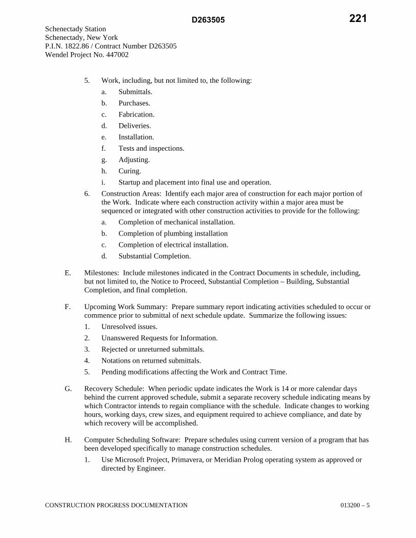
Schenectady Station Schenectady, New York P.I.N. 1822.86 / Contract Number D263505 Wendel Project No. 447002
CONSTRUCTION PROGRESS DOCUMENTATION 013200 – 5
5. Work, including, but not limited to, the following: a. Submittals. b. Purchases. c. Fabrication. d. Deliveries. e. Installation. f. Tests and inspections. g. Adjusting. h. Curing. i. Startup and placement into final use and operation.
6. Construction Areas: Identify each major area of construction for each major portion of the Work. Indicate where each construction activity within a major area must be sequenced or integrated with other construction activities to provide for the following: a. Completion of mechanical installation. b. Completion of plumbing installation c. Completion of electrical installation. d. Substantial Completion.
E. Milestones: Include milestones indicated in the Contract Documents in schedule, including, but not limited to, the Notice to Proceed, Substantial Completion – Building, Substantial Completion, and final completion.
F. Upcoming Work Summary: Prepare summary report indicating activities scheduled to occur or commence prior to submittal of next schedule update. Summarize the following issues: 1. Unresolved issues. 2. Unanswered Requests for Information. 3. Rejected or unreturned submittals. 4. Notations on returned submittals. 5. Pending modifications affecting the Work and Contract Time.
G. Recovery Schedule: When periodic update indicates the Work is 14 or more calendar days behind the current approved schedule, submit a separate recovery schedule indicating means by which Contractor intends to regain compliance with the schedule. Indicate changes to working hours, working days, crew sizes, and equipment required to achieve compliance, and date by which recovery will be accomplished.
H. Computer Scheduling Software: Prepare schedules using current version of a program that has been developed specifically to manage construction schedules. 1. Use Microsoft Project, Primavera, or Meridian Prolog operating system as approved or
directed by Engineer.
221D263505
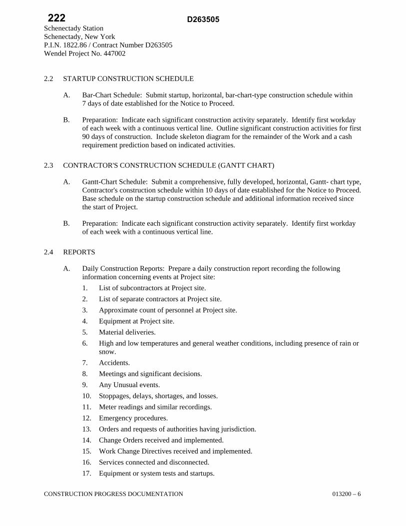
Schenectady Station Schenectady, New York P.I.N. 1822.86 / Contract Number D263505 Wendel Project No. 447002
CONSTRUCTION PROGRESS DOCUMENTATION 013200 – 6
2.2 STARTUP CONSTRUCTION SCHEDULE
A. Bar-Chart Schedule: Submit startup, horizontal, bar-chart-type construction schedule within 7 days of date established for the Notice to Proceed.
B. Preparation: Indicate each significant construction activity separately. Identify first workday of each week with a continuous vertical line. Outline significant construction activities for first 90 days of construction. Include skeleton diagram for the remainder of the Work and a cash requirement prediction based on indicated activities.
2.3 CONTRACTOR'S CONSTRUCTION SCHEDULE (GANTT CHART)
A. Gantt-Chart Schedule: Submit a comprehensive, fully developed, horizontal, Gantt- chart type, Contractor's construction schedule within 10 days of date established for the Notice to Proceed. Base schedule on the startup construction schedule and additional information received since the start of Project.
B. Preparation: Indicate each significant construction activity separately. Identify first workday of each week with a continuous vertical line.
2.4 REPORTS
A. Daily Construction Reports: Prepare a daily construction report recording the following information concerning events at Project site: 1. List of subcontractors at Project site. 2. List of separate contractors at Project site. 3. Approximate count of personnel at Project site. 4. Equipment at Project site. 5. Material deliveries. 6. High and low temperatures and general weather conditions, including presence of rain or
snow. 7. Accidents. 8. Meetings and significant decisions. 9. Any Unusual events. 10. Stoppages, delays, shortages, and losses. 11. Meter readings and similar recordings. 12. Emergency procedures. 13. Orders and requests of authorities having jurisdiction. 14. Change Orders received and implemented. 15. Work Change Directives received and implemented. 16. Services connected and disconnected. 17. Equipment or system tests and startups.
222 D263505

Schenectady Station Schenectady, New York P.I.N. 1822.86 / Contract Number D263505 Wendel Project No. 447002
CONSTRUCTION PROGRESS DOCUMENTATION 013200 – 7
18. Partial completions and occupancies. 19. Substantial Completions authorized.
B. Material Location Reports: At weekly intervals, prepare and submit a comprehensive list of materials delivered to and stored at Project site. List shall be cumulative, showing materials previously reported plus items recently delivered. Include with list a statement of progress on and delivery dates for materials or items of equipment fabricated or stored away from Project site. Indicate the following categories for stored materials: 1. Material stored prior to previous report and remaining in storage. 2. Material stored prior to previous report and since removed from storage and installed. 3. Material stored following previous report and remaining in storage.
C. Site Condition Reports: Immediately on discovery of a difference between site conditions and the Contract Documents, prepare and submit a detailed report. Submit with a Request for Information. Include a detailed description of the differing conditions, together with recommendations for changing the Contract Documents.
PART 3 – EXECUTION
3.1 CONTRACTOR'S CONSTRUCTION SCHEDULE
A. Scheduling Consultant: Contractor to employ skilled personnel with experience in scheduling, planning, evaluation, and reporting.
B. Contractor's Construction Schedule Updating: At weekly intervals, update schedule to reflect actual construction progress and activities. 1. Revise schedule immediately after each meeting or other activity where revisions have
been recognized or made. Issue updated schedule concurrently with the report of each such meeting.
2. Include a report with updated schedule that indicates every change, including, but not limited to, changes in logic, durations, actual starts and finishes, and activity durations.
3. As the Work progresses, indicate final completion percentage for each activity.
C. Distribution: Distribute copies of approved schedule to Architect/Engineer of Record, Engineer, and Owner and other parties identified by Contractor with a need-to-know schedule responsibility. 1. When revisions are made, distribute updated schedules to the same parties. Delete parties
from distribution when they have completed their assigned portion of the Work and are no longer involved in performance of construction activities.
END OF SECTION 013200
223D263505

Schenectady Station Schenectady, New York P.I.N. 1822.86 / Contract Number D263505 Wendel Project No. 447002
SUBMITTAL PROCEDURES 013300 – 1
SECTION 013300 – SUBMITTAL PROCEDURES
PART 1 – GENERAL
1.1 RELATED DOCUMENTS
A. Drawings and general provisions of the Contract, including General and Supplementary Conditions and other Division 01through Division 33 Specification Sections, apply to this Section.
1.2 SUMMARY
A. Section includes requirements for the submittal schedule and administrative and procedural requirements for submitting Shop Drawings, Product Data, Samples, and other submittals.
B. Related Requirements: 1. Section 013200 "Construction Progress Documentation" for submitting schedules and
reports, including Contractor's construction schedule. 2. Section 017823 "Operation and Maintenance Data" for submitting operation and
maintenance manuals. 3. Section 017839 "Project Record Documents" for submitting record Drawings, record
Specifications, and record Product Data.
1.3 DEFINITIONS
A. Definitions: Basic contract definitions are included in the Conditions of the Contract.
B. "Indicated" refers to graphic representations, notes, or schedules on the Drawings; or to other paragraphs or schedules in the Specifications and similar requirements in the Contract Documents. Terms such as "shown," "noted," "scheduled," and "specified" are used to help the user locate the reference. Location is not limited.
C. "Directed," "requested," "authorized," "selected," "approved," "required," and "permitted" mean directed by the Architect, requested by the Architect, and similar phrases.
D. "Approved," when used in conjunction with the Architect's action on the Contractor's submittals, applications, and requests, is limited to the Architect's duties and responsibilities as stated in the Conditions of the Contract.
E. "Regulations" includes laws, ordinances, statutes, and lawful orders issued by authorities having jurisdiction, as well as rules, conventions, and agreements within the construction industry that control performance of the Work.
224 D263505

Schenectady Station Schenectady, New York P.I.N. 1822.86 / Contract Number D263505 Wendel Project No. 447002
SUBMITTAL PROCEDURES 013300 – 2
F. Action Submittals: Written and graphic information and physical samples that require Architect's, Engineer’s and Owner’s responsive action. Action submittals are those submittals indicated in individual Specification Sections as "action submittals."
G. Informational Submittals: Written and graphic information and physical samples that do not require Architect's, Engineer’s and Owner’s responsive action. Submittals may be rejected for not complying with requirements. Informational submittals are those submittals indicated in individual Specification Sections as "informational submittals."
H. File Transfer Protocol (FTP): Communications protocol that enables transfer of files to and from another computer over a network and that serves as the basis for standard Internet protocols. An FTP site is a portion of a network located outside of network firewalls within which internal and external users are able to access files.
I. Portable Document Format (PDF): An open standard file format licensed by Adobe Systems used for representing documents in a device-independent and display resolution independent fixed-layout document format.
1.4 ACTION SUBMITTALS
A. Submittal Schedule: Submit a schedule of submittals, arranged in chronological order by dates required by construction schedule. Include time required for review, ordering, manufacturing, fabrication, and delivery when establishing dates. Include additional time required for making corrections or revisions to submittals noted by Architect and additional time for handling and reviewing submittals required by those corrections. 1. Coordinate submittal schedule with list of subcontracts, the schedule of values, and
Contractor's construction schedule. 2. Initial Submittal: Submit concurrently with startup construction schedule. Include
submittals required during the first 60 days of construction. List those submittals required to maintain orderly progress of the Work and those required early because of long lead time for manufacture or fabrication.
3. Final Submittal: Submit concurrently with the first complete submittal of Contractor's construction schedule. a. Submit revised submittal schedule to reflect changes in current status and timing for
submittals. 4. Format: Arrange the following information in a tabular format:
a. Scheduled date for first submittal. b. Specification Section number and title. c. Submittal category: Action; informational. d. Name of subcontractor. e. Description of the Work covered. f. Scheduled date for Architect's and Engineer's final release or approval. g. Scheduled date of fabrication.
225D263505

Schenectady Station Schenectady, New York P.I.N. 1822.86 / Contract Number D263505 Wendel Project No. 447002
SUBMITTAL PROCEDURES 013300 – 3
h. Scheduled dates for purchasing. i. Scheduled dates for installation. j. Activity or event number.
1.5 SUBMITTAL ADMINISTRATIVE REQUIREMENTS
A. Architect's Digital Data Files: Electronic digital data files of the Contract Drawings will be provided by Architect for Contractor's use in preparing submittals. 1. Architect will furnish Contractor one set of digital data drawing files of the Contract
Drawings for use in preparing Shop Drawings and Project record drawings. a. Architect makes no representations as to the accuracy or completeness of digital
data drawing files as they relate to the Contract Drawings. b. Digital Drawing Software Program: The Contract Drawings are available in
AutoCAD. c. Subject to contract award and prior to the Architect providing digital data drawing
files, the Contractor shall execute and sign a data licensing agreement in the form of AIA Document C106, Digital Data Licensing Agreement. The contractor shall obtain Document C106 from the AIA. Further, the contractor shall include any costs associated with obtaining and executing this document.
d. The following digital data files will by furnished for each appropriate discipline: 1) Floor plans. 2) Reflected ceiling plans. 3) Roof plans 4) Building elevations. 5) Building and wall sections and details. 6) Door and window Schedules.
B. Coordination: Coordinate preparation and processing of submittals with performance of construction activities. 1. Coordinate each submittal with fabrication, purchasing, testing, delivery, other
submittals, and related activities that require sequential activity. 2. Submit all submittal items required for each Specification Section concurrently unless
partial submittals for portions of the Work are indicated on approved submittal schedule. 3. Submit action submittals and informational submittals required by the same Specification
Section as separate packages under separate transmittals. 4. Coordinate transmittal of different types of submittals for related parts of the Work so
processing will not be delayed because of need to review submittals concurrently for coordination. a. Architect, Engineer and Owner reserve the right to withhold action on a submittal
requiring coordination with other submittals until related submittals are received.
226 D263505

Schenectady Station Schenectady, New York P.I.N. 1822.86 / Contract Number D263505 Wendel Project No. 447002
SUBMITTAL PROCEDURES 013300 – 4
C. Processing Time: Allow time for submittal review, including time for resubmittals, as follows. Time for review shall commence on Engineer’s/Architect's receipt of submittal. No extension of the Contract Time will be authorized because of failure to transmit submittals enough in advance of the Work to permit processing, including resubmittals. 1. Initial Review: Allow 15 days for initial review of each submittal. Allow additional time
if coordination with subsequent submittals is required. Engineer will advise Contractor when a submittal being processed must be delayed for coordination.
2. Intermediate Review: If intermediate submittal is necessary, process it in same manner as initial submittal.
3. Resubmittal Review: Allow 15 days for review of each resubmittal. 4. Sequential Review: Where sequential review of submittals by Architect's consultants,
Owner, Engineer or other parties is indicated, allow 21 days for initial review of each submittal.
D. Electronic Submittals: Identify and incorporate information in each electronic submittal file as follows: 1. Assemble complete submittal package into a single indexed file incorporating submittal
requirements of a single Specification Section and transmittal form with links enabling navigation to each item.
2. Name file with submittal number or other unique identifier, including revision identifier. a. File name shall use project identifier and Specification Section number followed by
a decimal point and then a sequential number (e.g., LNHS-061000.01). Resubmittals shall include an alphabetic suffix after another decimal point (e.g., LNHS-061000.01.A).
3. Provide means for insertion to permanently record Contractor's review and approval markings and action taken by Architect and Engineer.
4. Transmittal Form for Electronic Submittals: Use software-generated form from electronic project management software acceptable to Engineer and Owner, containing the following information: a. Project name. b. Date. c. Name and address of Architect. d. Name of Engineer. e. Name of Contractor. f. Name of firm or entity that prepared submittal. g. Names of subcontractor, manufacturer, and supplier. h. Category and type of submittal. i. Submittal purpose and description. j. Specification Section number and title. k. Specification paragraph number or drawing designation and generic name for each
of multiple items.
227D263505

Schenectady Station Schenectady, New York P.I.N. 1822.86 / Contract Number D263505 Wendel Project No. 447002
SUBMITTAL PROCEDURES 013300 – 5
l. Drawing number and detail references, as appropriate. m. Location(s) where product is to be installed, as appropriate. n. Related physical samples submitted directly. o. Indication of full or partial submittal. p. Transmittal number, numbered consecutively. q. Submittal and transmittal distribution record. r. Other necessary identification. s. Remarks.
5. Metadata: Include the following information as keywords in the electronic submittal file metadata: a. Project name. b. Number and title of appropriate Specification Section. c. Manufacturer name. d. Product name.
E. Options: Identify options requiring selection by Architect.
F. Deviations and Additional Information: On an attached separate sheet, prepared on Contractor's letterhead, record relevant information, requests for data, revisions other than those requested by Architect, Engineer and Owner on previous submittals, and deviations from requirements in the Contract Documents, including minor variations and limitations. Include same identification information as related submittal.
G. Resubmittals: Make resubmittals in same form and number of copies as initial submittal. 1. Note date and content of previous submittal. 2. Note date and content of revision in label or title block and clearly indicate extent of
revision. 3. Resubmit submittals until they are marked with approval notation from Architect's,
Engineer’s and Owner's action stamp.
H. Distribution: Furnish copies of final submittals to manufacturers, subcontractors, suppliers, fabricators, installers, authorities having jurisdiction, and others as necessary for performance of construction activities. Show distribution on transmittal forms.
I. J. Use for Construction: Retain complete copies of submittals on Project site. Use only final action submittals that are marked with approval notation from Architect's, Engineer’s and Owner's action stamp.
228 D263505

Schenectady Station Schenectady, New York P.I.N. 1822.86 / Contract Number D263505 Wendel Project No. 447002
SUBMITTAL PROCEDURES 013300 – 6
PART 2 – PRODUCTS
2.1 SUBMITTAL PROCEDURES
A. General Submittal Procedure Requirements: Prepare and submit submittals required by individual Specification Sections. Types of submittals are indicated in individual Specification Sections. 1. Post electronic submittals as PDF electronic files directly to Project Web site specifically
established for Project. a. Architect, through Engineer, will return annotated file. Annotate and retain one
copy of file as an electronic Project record document file. 2. Submit electronic submittals through acceptable Project On-Line Management host as
PDF electronic files. a. Architect, through Engineer, will return annotated file. Annotate and retain one
copy of file as an electronic Project record document file. 3. Certificates and Certifications Submittals: Provide a statement that includes signature of
entity responsible for preparing certification. Certificates and certifications shall be signed by an officer or other individual authorized to sign documents on behalf of that entity. a. Provide a digital signature with digital certificate on electronically submitted
certificates and certifications where indicated. b. Provide a notarized statement on original paper copy certificates and certifications
where indicated.
B. Product Data: Collect information into a single submittal for each element of construction and type of product or equipment. 1. If information must be specially prepared for submittal because standard published data
are not suitable for use, submit as Shop Drawings, not as Product Data. 2. Mark each copy of each submittal to show which products and options are applicable. 3. Include the following information, as applicable:
a. Manufacturer's catalog cuts. b. Manufacturer's product specifications. c. Standard color charts. d. Statement of compliance with specified referenced standards. e. Testing by recognized testing agency. f. Application of testing agency labels and seals. g. Notation of coordination requirements. h. Availability and delivery time information.
4. For equipment, include the following in addition to the above, as applicable: a. Wiring diagrams showing factory-installed wiring. b. Printed performance curves.
229D263505

Schenectady Station Schenectady, New York P.I.N. 1822.86 / Contract Number D263505 Wendel Project No. 447002
SUBMITTAL PROCEDURES 013300 – 7
c. Operational range diagrams. d. Clearances required to other construction, if not indicated on accompanying Shop
Drawings. 5. Submit Product Data before or concurrent with Samples. 6. Submit Product Data in the following format:
a. PDF electronic file. b. Three paper copies of Product Data unless otherwise indicated. Architect will
return two copies.
C. Shop Drawings: Prepare Project-specific information, drawn accurately to scale. Do not base Shop Drawings on reproductions of the Contract Documents or standard printed data. 1. Preparation: Fully illustrate requirements in the Contract Documents. Include the
following information, as applicable: a. Identification of products. b. Schedules. c. Compliance with specified standards. d. Notation of coordination requirements. e. Notation of dimensions established by field measurement. f. Relationship and attachment to adjoining construction clearly indicated. g. Seal and signature of professional engineer if specified.
2. Sheet Size: Except for templates, patterns, and similar full-size drawings, submit Shop Drawings on sheets at least 8-1/2 by 11 inches, but no larger than 30 by 42 inches.
3. Submit Shop Drawings in the following format: a. PDF electronic file.
4. BIM File Incorporation: Develop and incorporate Shop Drawing files into Building Information Model established for Project. a. Prepare Shop Drawings in the following format: Same digital data software
program, version, and operating system as the original Drawings. b. Refer to Section 013100 "Project Management and Coordination" for requirements
for coordination drawings.
D. Samples: Submit Samples for review of kind, color, pattern, and texture for a check of these characteristics with other elements and for a comparison of these characteristics between submittal and actual component as delivered and installed. 1. Transmit Samples that contain multiple, related components such as accessories together
in one submittal package. 2. Identification: Attach label on unexposed side of Samples that includes the following:
a. Generic description of Sample. b. Product name and name of manufacturer. c. Sample source.
230 D263505

Schenectady Station Schenectady, New York P.I.N. 1822.86 / Contract Number D263505 Wendel Project No. 447002
SUBMITTAL PROCEDURES 013300 – 8
d. Number and title of applicable Specification Section. e. Specification paragraph number and generic name of each item.
3. For projects where electronic submittals are required, provide corresponding electronic submittal of Sample transmittal, digital image file illustrating Sample characteristics, and identification information for record.
4. Disposition: Maintain sets of approved Samples at Project site, available for quality control comparisons throughout the course of construction activity. Sample sets may be used to determine final acceptance of construction associated with each set. a. Samples that may be incorporated into the Work are indicated in individual
Specification Sections. Such Samples must be in an undamaged condition at time of use.
b. Samples not incorporated into the Work, or otherwise designated as Engineer or Owner's property, are the property of Contractor.
5. Samples for Initial Selection: Submit manufacturer's color charts consisting of units or sections of units showing the full range of colors, textures, and patterns available. a. Number of Samples: Submit one full set(s) of available choices where color,
pattern, texture, or similar characteristics are required to be selected from manufacturer's product line. Architect, through Engineer, will return submittal with options selected.
6. Samples for Verification: Submit full-size units or Samples of size indicated, prepared from same material to be used for the Work, cured and finished in manner specified, and physically identical with material or product proposed for use, and that show full range of color and texture variations expected. Samples include, but are not limited to, the following: partial sections of manufactured or fabricated components; small cuts or containers of materials; complete units of repetitively used materials; swatches showing color, texture, and pattern; color range sets; and components used for independent testing and inspection. a. Number of Samples: Submit three sets of Samples. Architect will retain two
Sample sets; remainder will be returned. 1) Submit a single Sample where assembly details, workmanship, fabrication
techniques, connections, operation, and other similar characteristics are to be demonstrated.
2) If variation in color, pattern, texture, or other characteristic is inherent in material or product represented by a Sample, submit at least three sets of paired units that show approximate limits of variations.
E. Product Schedule: As required in individual Specification Sections, prepare a written summary indicating types of products required for the Work and their intended location. Include the following information in tabular form: 1. Type of product. Include unique identifier for each product indicated in the Contract
Documents or assigned by Contractor if none is indicated. 2. Manufacturer and product name, and model number if applicable. 3. Number and name of room or space.
231D263505

Schenectady Station Schenectady, New York P.I.N. 1822.86 / Contract Number D263505 Wendel Project No. 447002
SUBMITTAL PROCEDURES 013300 – 9
4. Location within room or space. 5. Submit product schedule in the following format:
a. PDF electronic file. b. Three paper copies of product schedule or list unless otherwise indicated. Architect
will return two copies.
F. Coordination Drawing Submittals: Comply with requirements specified in Section 013100 "Project Management and Coordination."
G. Contractor's Construction Schedule: Comply with requirements specified in Section 013200 "Construction Progress Documentation."
H. Closeout Submittals and Maintenance Material Submittals: Comply with requirements specified in Section 017700 "Closeout Procedures."
I. Maintenance Data: Comply with requirements specified in Section 017823 "Operation and Maintenance Data."
J. Qualification Data: Prepare written information that demonstrates capabilities and experience of firm or person. Include lists of completed projects with project names and addresses, contact information of architects, engineers and owners, and other information specified.
K. Welding Certificates: Prepare written certification that welding procedures and personnel comply with requirements in the Contract Documents. Submit record of Welding Procedure Specification and Procedure Qualification Record on AWS forms. Include names of firms and personnel certified.
L. Installer Certificates: Submit written statements on manufacturer's letterhead certifying that Installer complies with requirements in the Contract Documents and, where required, is authorized by manufacturer for this specific Project.
M. Manufacturer Certificates: Submit written statements on manufacturer's letterhead certifying that manufacturer complies with requirements in the Contract Documents. Include evidence of manufacturing experience where required.
N. Product Certificates: Submit written statements on manufacturer's letterhead certifying that product complies with requirements in the Contract Documents.
O. Material Certificates: Submit written statements on manufacturer's letterhead certifying that material complies with requirements in the Contract Documents.
P. Material Test Reports: Submit reports written by a qualified testing agency, on testing agency's standard form, indicating and interpreting test results of material for compliance with requirements in the Contract Documents.
Q. Product Test Reports: Submit written reports indicating that current product produced by manufacturer complies with requirements in the Contract Documents. Base reports on
232 D263505

Schenectady Station Schenectady, New York P.I.N. 1822.86 / Contract Number D263505 Wendel Project No. 447002
SUBMITTAL PROCEDURES 013300 – 10
evaluation of tests performed by manufacturer and witnessed by a qualified testing agency, or on comprehensive tests performed by a qualified testing agency.
R. Research Reports: Submit written evidence, from a model code organization acceptable to authorities having jurisdiction, that product complies with building code in effect for Project. Include the following information: 1. Name of evaluation organization. 2. Date of evaluation. 3. Time period when report is in effect. 4. Product and manufacturers' names. 5. Description of product. 6. Test procedures and results. 7. Limitations of use.
S. Preconstruction Test Reports: Submit reports written by a qualified testing agency, on testing agency's standard form, indicating and interpreting results of tests performed before installation of product, for compliance with performance requirements in the Contract Documents.
T. Compatibility Test Reports: Submit reports written by a qualified testing agency, on testing agency's standard form, indicating and interpreting results of compatibility tests performed before installation of product. Include written recommendations for primers and substrate preparation needed for adhesion.
U. Field Test Reports: Submit written reports indicating and interpreting results of field tests performed either during installation of product or after product is installed in its final location, for compliance with requirements in the Contract Documents.
V. Design Data: Prepare and submit written and graphic information, including, but not limited to, performance and design criteria, list of applicable codes and regulations, and calculations. Include list of assumptions and other performance and design criteria and a summary of loads. Include load diagrams if applicable. Provide name and version of software, if any, used for calculations. Include page numbers.
2.2 DELEGATED-DESIGN SERVICES
A. Performance and Design Criteria: Where professional design services or certifications by a design professional are specifically required of Contractor by the Contract Documents, provide products and systems complying with specific performance and design criteria indicated. 1. If criteria indicated are not sufficient to perform services or certification required, submit
a written request for additional information to Architect.
B. Delegated-Design Services Certification: In addition to Shop Drawings, Product Data, and other required submittals, submit digitally signed PDF electronic file, three paper copies of certificate, signed and sealed by the responsible design professional, for each product and system specifically assigned to Contractor to be designed or certified by a design professional.
233D263505

Schenectady Station Schenectady, New York P.I.N. 1822.86 / Contract Number D263505 Wendel Project No. 447002
SUBMITTAL PROCEDURES 013300 – 11
1. Indicate that products and systems comply with performance and design criteria in the Contract Documents. Include list of codes, loads, and other factors used in performing these services.
C. BIM File Incorporation: Incorporate delegated-design drawing and data files into Building Information Model established for Project. 1. Prepare delegated-design drawings in the following format: Same digital data software
program, version, and operating system as the original Drawings.
PART 3 – EXECUTION
3.1 CONTRACTOR'S REVIEW
A. Action and Informational Submittals: Review each submittal and check for coordination with other Work of the Contract and for compliance with the Contract Documents. Note corrections and field dimensions. Mark with approval stamp before submitting to Architect and Engineer.
B. Project Closeout and Maintenance Material Submittals: See requirements in Section 017700 "Closeout Procedures."
C. Approval Stamp: Stamp each submittal with a uniform, approval stamp. Include Project name and location, submittal number, Specification Section title and number, name of reviewer, date of Contractor's approval, and statement certifying that submittal has been reviewed, checked, and approved for compliance with the Contract Documents.
3.2 ARCHITECT'S ACTION
A. Action Submittals: Architect will review each submittal, make marks to indicate corrections or revisions required, and return it. Architect will stamp each submittal with an action stamp and will mark stamp appropriately to indicate action.
B. Informational Submittals: Architect will review each submittal and will not return it, or will return it if it does not comply with requirements. Architect will forward each submittal to appropriate party.
C. Partial submittals prepared for a portion of the Work will be reviewed when use of partial submittals has received prior approval from Architect.
D. Incomplete submittals are unacceptable, will be considered nonresponsive, and will be returned for resubmittal without review.
E. Submittals not required by the Contract Documents may be returned by the Engineer or Architect without action.
END OF SECTION 013300
234 D263505

Schenectady Station Schenectady, New York P.I.N. 1822.86 / Contract Number D263505 Wendel Project No. 447002
SPECIAL INSPECTIONS AND STRUCTURAL TESTING 014100 - 1
SECTION 014100 – SPECIAL INSPECTIONS AND STRUCTURAL TESTING
PART 1 - GENERAL
1.1 RELATED DOCUMENTS
A. Drawings and general provisions of the Contract, including General and Supplementary Conditions and other Division 1 Specification Sections, apply to this Section.
1.2 GENERAL REQUIREMENTS
A. Provide Special Inspections and Structural Testing in accordance with Chapter 17 of the 2012 International Building Code (2012 IBC).
B. Special Inspections and Structural Testing shall be in accordance with CASE National Practice Guideline for Special Inspections.
C. The program of Special Inspection and Structural Testing is a Quality Assurance program intended to ensure that the work is performed in accordance with the Contract Documents.
D. This specification section is intended to inform the Contractor of the Owner’s quality assurance program and the extent of the Contractor’s responsibilities. This specification section is also intended to notify the Special Inspector, Testing Laboratory, and other Agents of the Special Inspector of their requirements and responsibilities.
E. Related Specification Sections include the following:
1. Division 01 Section "Quality Requirements" for testing agency procedures and administrative requirements.
2. Division 03 Sections "Cast-in-Place Concrete – Station Building" for material testing and other quality requirements.
3. Division 04 Section "Unit Masonry" for material testing and other quality requirements. 4. Division 05 Sections "Structural Steel Framing" and “Steel Decking” for material testing
and other quality requirements. 5. Division 31 Section "Earth Work – Station Building" for material testing and other
quality requirements.
1.3 SCHEDULE OF INSPECTIONS AND TESTS
A. Required inspections and tests are described in the individual Specification Sections for the items to be inspected or tested and the “Schedule of Special Inspection Services”, which is included at the end of this Section.
235D263505
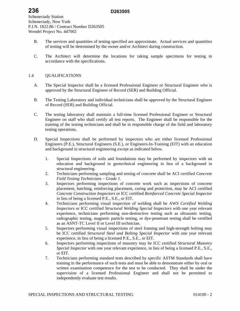
Schenectady Station Schenectady, New York P.I.N. 1822.86 / Contract Number D263505 Wendel Project No. 447002
SPECIAL INSPECTIONS AND STRUCTURAL TESTING 014100 - 2
B. The services and quantities of testing specified are approximate. Actual services and quantities of testing will be determined by the owner and/or Architect during construction.
C. The Architect will determine the locations for taking sample specimens for testing in accordance with the specifications.
1.4 QUALIFICATIONS
A. The Special Inspector shall be a licensed Professional Engineer or Structural Engineer who is approved by the Structural Engineer of Record (SER) and Building Official.
B. The Testing Laboratory and individual technicians shall be approved by the Structural Engineer of Record (SER) and Building Official.
C. The testing laboratory shall maintain a full-time licensed Professional Engineer or Structural Engineer on staff who shall certify all test reports. The Engineer shall be responsible for the training of the testing technicians and shall be in responsible charge of the field and laboratory testing operations.
D. Special Inspections shall be performed by inspectors who are either licensed Professional Engineers (P.E.), Structural Engineers (S.E.), or Engineers-In-Training (EIT) with an education and background in structural engineering except as indicated below.
1. Special Inspections of soils and foundations may be performed by inspectors with an education and background in geotechnical engineering in lieu of a background in structural engineering.
2. Technicians performing sampling and testing of concrete shall be ACI certified Concrete Field Testing Technicians – Grade 1.
3. Inspectors performing inspections of concrete work such as inspections of concrete placement, batching, reinforcing placement, curing and protection, may be ACI certified Concrete Construction Inspectors or ICC certified Reinforced Concrete Special Inspector in lieu of being a licensed P.E., S.E., or EIT.
4. Technicians performing visual inspection of welding shall be AWS Certified Welding Inspectors or ICC certified Structural Welding Special Inspectors with one year relevant experience, technicians performing non-destructive testing such as ultrasonic testing, radiographic testing, magnetic particle testing, or dye-penetrant testing shall be certified as an ASNT-TC Level II or Level III technician.
5. Inspectors performing visual inspections of steel framing and high-strength bolting may be ICC certified Structural Steel and Bolting Special Inspector with one year relevant experience, in lieu of being a licensed P.E., S.E., or EIT.
6. Inspectors performing inspections of masonry may be ICC certified Structural Masonry Special Inspector with one year relevant experience, in lieu of being a licensed P.E., S.E., or EIT.
7. Technicians performing standard tests described by specific ASTM Standards shall have training in the performance of such tests and must be able to demonstrate either by oral or written examination competence for the test to be conducted. They shall be under the supervision of a licensed Professional Engineer and shall not be permitted to independently evaluate test results.
236 D263505

Schenectady Station Schenectady, New York P.I.N. 1822.86 / Contract Number D263505 Wendel Project No. 447002
SPECIAL INSPECTIONS AND STRUCTURAL TESTING 014100 - 3
1.5 SUBMITTALS
A. If requested, the Special Inspector and Testing Laboratory shall submit to the SER and Building Official for review, a copy of their qualifications which shall include the names and qualifications of each of the individual inspectors and technicians who will be performing inspections or tests.
B. The Special Inspector and Testing Laboratory shall disclose any past or present business relationship or potential conflict of interest with the Contractor or any of the Subcontractors whose work will be inspected or tested.
1.6 PAYMENT
A. The Owner shall engage and pay for the services of the Special Inspector, Agents of the Special Inspector, and Testing Laboratory.
B. If any materials which require Special Inspections are fabricated in a plant which is not located within 100 miles of the project, the Contractor shall be responsible for the travel expenses of the Special Inspector or Testing Laboratory.
C. The Contractor shall be responsible for the cost of any retesting or reinspection of work which fails to comply with the requirements of the Contract Documents.
1.7 CONTRACTOR RESPONSIBILITIES
A. Without exception, work which fails to comply with the requirements of the Contract Documents or work which has not been inspected is to be immediately removed and replaced, at the Contractor’s cost.
B. The Contractor shall cooperate with the Special Inspector and his agents so that the Special Inspections and testing may be performed without hindrance.
C. The Contractor shall review the Statement of Special Inspections and shall be responsible for coordinating and scheduling inspections and tests. The Contractor shall notify the Special Inspector or Testing Laboratory at least 24 hours in advance of a required inspection or test. Uninspected work that required inspection may be rejected solely on failure of notification.
D. The Contractor shall provide incidental labor and facilities to provide access to the work to be inspected or tested, to obtain and handle samples at the site or at source of products to be tested, to facilitate tests and inspections, storage and curing of test samples.
1. Construct a storage box on site of sufficient size to store concrete cylinders which will afford protection as required by ASTM C-31.
2. Provide the laboratory with representative initial samples, in requested quantities. 3. When source, quality or characteristic of an approved material changes or indicates lack
of compliance with Contract requirements, submit additional samples of materials to testing laboratory.
237D263505

Schenectady Station Schenectady, New York P.I.N. 1822.86 / Contract Number D263505 Wendel Project No. 447002
SPECIAL INSPECTIONS AND STRUCTURAL TESTING 014100 - 4
4. Patch area where samples are taken for purposes of testing to the satisfaction of the Architect.
E. The Contractor shall keep at the project site the latest set of construction drawings, field sketches, approved shop drawings, and specifications for use by the inspectors and testing technicians.
F. The Special Inspection program shall in no way relieve the Contractor of his obligation to perform work in accordance with the requirements of the Contract Documents or from implementing an effective Quality Control program. All work that is to be subjected to Special Inspections shall first be reviewed by the Contractor’s quality control personnel.
G. The Contractor shall be solely responsible for construction site safety.
1.8 LIMITS ON AUTHORITY
A. The Special Inspector or Testing Laboratory may not release, revoke, alter, or enlarge on the requirements of the Contract Documents.
B. The Special Inspector or Testing Laboratory will not have control over the Contractor’s means and methods of construction.
C. The Special Inspector or Testing Laboratory shall not be responsible for construction site safety.
D. The Special Inspector or Testing Laboratory has no authority to stop the work.
1.9 STATEMENT OF SPECIAL INSPECTIONS
A. The Statement of Special Inspections will be prepared by the Structural Engineer of Record (SER) and shall be submitted with the application for Building Permit.
1.10 RECORDS AND REPORTS
A. Detailed daily reports shall be prepared for each inspection or test and submitted to the Special Inspector. Reports shall include:
1. Date of test or inspection. 2. Name of inspector or technician. 3. Location of specific areas tested or inspected. 4. Description of test or inspection and results. 5. Applicable ASTM standard. 6. Weather conditions. 7. Signature of Special Inspector or Technician.
238 D263505

Schenectady Station Schenectady, New York P.I.N. 1822.86 / Contract Number D263505 Wendel Project No. 447002
SPECIAL INSPECTIONS AND STRUCTURAL TESTING 014100 - 5
B. The Special Inspector shall submit interim reports to the Building Official, as required, which include all inspections and test reports received during that period. Copies shall be sent to the SER, Architect, and Contractor.
C. Any discrepancies from the Contract Documents found during a Special Inspection shall be immediately reported to the Contractor. If the discrepancies are not corrected, the Special Inspector shall notify the SER and Building Official. Reports shall document all discrepancies identified and the corrective action taken.
D. The Testing Laboratory shall immediately notify the Special Inspector and the SER by telephone, fax, or e-mail of any results which fail to comply with the requirements of the Contract Documents.
E. Reports shall be submitted to the Special Inspector within 7 days of the inspection or test. Hand written reports may be submitted if final typed copies are not available.
F. At the completion of the work requiring Special Inspections, each inspection agency and testing laboratory shall provide a statement to the Special Inspector that all work was completed in substantial conformance with the Contract Documents and that all appropriate inspections and tests were performed.
1.11 FINAL REPORT OF SPECIAL INSPECTIONS
A. The Final Report of Special Inspections shall be completed by the Special Inspector and submitted to the SER and Building Official prior to the issuance of a Certificate of Use and Occupancy.
B. The Final Report of Special Inspections will certify that all required inspections have been performed and will itemize any discrepancies that were not corrected or resolved.
PART 2 - PRODUCTS (Not Applicable)
PART 3 - EXECUTION (Not Applicable)
END OF SECTION 014100
239D263505

3 7 5 E s s j a y R o a d , S u i t e 2 0 0 Wi l l i a ms v i l l e , N e w Y o r k 1 4 2 2 1 P 7 1 6 . 6 8 8 . 0 7 6 6 F 7 1 6 . 6 2 5 . 6 8 2 5
Statement of Special Inspections
Statement of Special Inspections
Project: Schenectady Station Location: Schenectady, NY Owner: NYSDOT Owner’s Address: Albany, NY
Architect/ Engineer of Record: Wendel – Buffalo, NY
This Statement of Special Inspections is submitted as a condition for permit issuance in accordance with the Special Inspection requirements of the 2012 International Building Code (2012 IBC). It includes a Schedule of Special Inspection Services applicable to this project as well as the name of the Special Inspector and the identity of other approved agencies intended to be retained for conducting these inspections. The Special Inspector shall keep records of all inspections and shall furnish inspection reports to the Building Official, Structural Engineer and Architect of Record. Discovered discrepancies shall be brought to the immediate attention of the Contractor for correction. If such discrepancies are not corrected, the discrepancies shall be brought to the attention of the Building Official, Structural Engineer and Architect of Record. The Special Inspection program does not relieve the Contractor of his or her responsibilities. Interim reports shall be submitted to the Building Official, Owner, Structural Engineer and Architect of Record. A Final Report of Special Inspections documenting completion of all required Special Inspections and correction of any discrepancies noted in the inspections shall be submitted prior to issuance of a Certificate of Use and Occupancy. Job site safety and means and methods of construction are solely the responsibility of the Contractor. Interim Report Frequency: Biweekly or per attached schedule.
Prepared by:
Design Professional Seal
(type or print name)
Signature Date Owner’s Authorization: Building Official’s Acceptance:
Signature Date Signature Date
240 D263505

Statement of Special Inspections
Sheet 1 of 5
Project: Schenectady Station
Schedule of Special Inspection Services
The following sheets comprise the required schedule of special inspections for this project. The construction divisions which require special inspections for this project are as follows:
Soils and Foundations Cold-Formed Steel Framing Concrete Construction Sprayed Fire Resistant Material Precast Concrete Wood Construction Masonry Construction Exterior Insulation and Finish System Structural Steel Construction Smoke Control
Inspection Agents Firm Address
1. Special Inspector
2. Testing Laboratory
3. Testing Laboratory
4. Other
Note: The qualifications of all personnel performing Special Inspection activities are subject to the approval of the Building Official. The inspectors and testing agencies shall be engaged by the Owner or the Owner’s Agent, and not by the Contractor or Subcontractor whose work is to be inspected or tested. Any conflict of interest must be disclosed to the Building Official, prior to commencing work. The credentials of all Inspectors and testing technicians shall be provided if requested. It is recommended that the person administering the Special Inspections program be a Professional Engineer experienced in the design of buildings.
241D263505

Schedule of Special Inspection Services
Schedule of Special Inspection Services Sheet 2 of 5
Minimum Qualifications Project: Schenectady Station
When the Structural Engineer of Record deems it appropriate that the individual performing a stipulated test of inspection have a specific certification or license as indicated below, such designation shall appear below the Agency Number on the Schedule.
Key for Minimum Qualifications of Inspection Agents (where indicated on Schedules) PE/SE Structural Engineer – a licensed SE or PE specializing in the design of building structures PE/GE Geotechnical Engineer – a licensed PE specializing in soil mechanics and foundations
EIT Engineering in Training – a graduate engineer who has passed the FE exam ACI-CFTT American Concrete Institute Certified Concrete Field Testing Technician ACI-CCI American Concrete Institute Certified Concrete Field Testing Technician ACI-LTT American Concrete Institute Certified Concrete Field Testing Technician ACI-STT American Concrete Institute Certified Concrete Field Testing Technician
AWS-CWI American Welding Society Certified Welding Inspector AWS/AISC-SSI American Welding Society Certified Structural Steel Inspector
ASNT American Society of Non-Destructive Testing - Level II or III ICC-SMSI International Code Council Certified Structural Masonry Special Inspector ICC -SWSI International Code Council Certified Structural Steel and Welding Special Inspector ICC -RCSI International Code Council Certified Reinforced Concrete Special Inspector NICET-CT Concrete Technician – Levels I, II, III & IV NICET -ST Soils Technician – Levels I, II, III & IV
NICET -GET Geotechnical Engineering Technician – Levels I, II, III & IV Note: The qualifications of inspection agents may be indicated on the Schedule in instances where the Structural Engineer deems such requirements are appropriate.
242 D263505
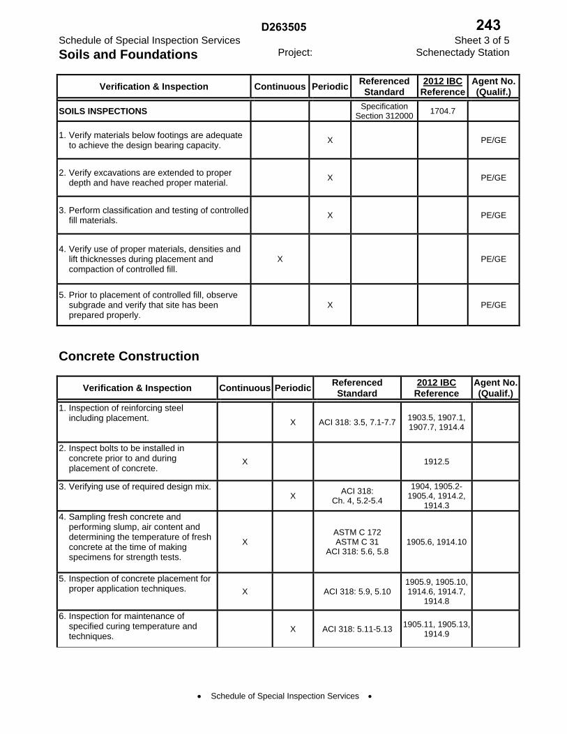
Schedule of Special Inspection Services
Schedule of Special Inspection Services Sheet 3 of 5
Soils and Foundations Project: Schenectady Station
Verification & Inspection Continuous PeriodicReferenced
Standard 2012 IBC
ReferenceAgent No.(Qualif.)
SOILS INSPECTIONS Specification
Section 312000 1704.7
1. Verify materials below footings are adequate to achieve the design bearing capacity.
X PE/GE
2. Verify excavations are extended to proper depth and have reached proper material.
X PE/GE
3. Perform classification and testing of controlled fill materials.
X PE/GE
4. Verify use of proper materials, densities and lift thicknesses during placement and compaction of controlled fill.
X PE/GE
5. Prior to placement of controlled fill, observe subgrade and verify that site has been prepared properly.
X PE/GE
Concrete Construction
Verification & Inspection Continuous PeriodicReferenced
Standard 2012 IBC
Reference Agent No.(Qualif.)
1. Inspection of reinforcing steel including placement. X ACI 318: 3.5, 7.1-7.7
1903.5, 1907.1, 1907.7, 1914.4
2. Inspect bolts to be installed in concrete prior to and during placement of concrete.
X 1912.5
3. Verifying use of required design mix. X
ACI 318: Ch. 4, 5.2-5.4
1904, 1905.2-1905.4, 1914.2,
1914.3
4. Sampling fresh concrete and performing slump, air content and determining the temperature of fresh concrete at the time of making specimens for strength tests.
X ASTM C 172 ASTM C 31
ACI 318: 5.6, 5.8 1905.6, 1914.10
5. Inspection of concrete placement for proper application techniques. X ACI 318: 5.9, 5.10
1905.9, 1905.10, 1914.6, 1914.7,
1914.8
6. Inspection for maintenance of specified curing temperature and techniques.
X ACI 318: 5.11-5.13 1905.11, 1905.13,
1914.9
243D263505

Schedule of Special Inspection Services
Schedule of Special Inspection Services Sheet 4 of 5
Masonry Construction - Level 1 Project: Schenectady Station
Inspection Task
Frequency of Inspection
Reference For Criteria Agent No.
(Qualif.) Continuous during task
listed
Periodically during task
listed
2012 IBC section
ACI 530/ ASCE 5/TMS 402a
ACI 530.1/ ASCE 6/TMS
602a
1. As masonry construction begins, the following shall be verified to ensure compliance:
a. Proportions of site-prepared mortar. X Art. 2.6A b. Construction of mortar joints. X Art. 3.3B c. Location of reinforcement and
anchorages. X Art. 3.4 and
3.6A
2. The inspection program shall verify: a. Size and location of structural
elements. X 3.3G
b. Type, size and location of anchors, including other details of anchorage of masonry to structural members, frames or other construction.
X Sec. 1.15.4, 2.1.2
c. Specified size, grade and type of reinforcement.
X Sec. 1.12 Art. 2.4, 3.4
d. Protection of masonry during cold weather (temperature < 40F) or hot weather (temperature > 90F).
X Sec. 2104.3, 2104.4
Art. 1.8
3. Prior to grouting, the following shall be verified to ensure compliance:
a. Grout space is clean. X Art. 3.2D b. Placement of reinforcement and
anchorages. X Sec. 1.12 Art. 3.4
c. Proportions of site-prepared grout. X Art. 2.6B d. Construction of mortar joints. X Art. 3.3B
4. a. Grout placement shall be verified to ensure compliance with code and Construction Document Provisions.
X Art. 3.5
5. Preparation of any required grout and/or mortar specimens shall be observed.
X Sec. 2105.3, 2105.4, 2105.5
Art. 1.4
244 D263505

Schedule of Special Inspection Services
Schedule of Special Inspection Services Sheet 5 of 5
Structural Steel Construction Project: Schenectady Station
Verification & Inspection Continuous PeriodicReferenced
Standard 2012 IBC
Reference Agent No.(Qualif.)
1. Material verification of high-strength bolts, nuts, and washers:
Applicable ASTM material specifications;
AISC ASD, Section A3.4; AISC LRFD,
Section A3.3
a. Identification markings to conform to ASTM standards specified in the approved construction documents.
b. Manufacturer’s certificate of compliance required.
X
X
2. Inspection of high-strength bolting: AISC LRFD Section M2.5
1704.3.3 a. Bearing-type connections. b. Slip-critical connections.
X X
3. Material verification of structural steel: a. Identification markings to conform to
ASTM standards specified in the approved construction documents.
b. Manufacturers’ certified mill test reports.
X
X
ASTM A 6 or ASTM A 568
ASTM A 6 or ASTM
A 568
1708.4
4. Material verification of weld filler materials:
AISC, ASD, Section A3.6; AISC LRFD, Section A3.5
a. Identification markings to conform to AWS specification in the approved construction documents.
b. Manufacturer’s certificate of compliance required.
X
X
5. Inspection of welding: AWS D1.1 1704.3.1 a. Structural steel:
1) Complete and partial penetration groove welds.
X
2) Multi-pass fillet welds. X 3) Single-pass fillet welds < 5/16. X 4) Floor and roof deck welds. X AWS D1.3
245D263505
Final Report of Special Inspections
Final Report of Special Inspections
Project: Schenectady Station
Location: Schenectady, NY
Owner: NYSDOT
Owner’s Address: Albany, NY
Special Inspector:
To the best of my information, knowledge and belief, the Special Inspections required for this project, and itemized in the Statement of Special Inspections submitted for permit, have been performed and all discovered discrepancies have been reported and resolved other than the following: Comments:
(Attach continuation sheets if required to complete the description of corrections.) Interim reports submitted prior to this final report form a basis for and are to be considered an integral part of this final report. Respectfully submitted, Special Inspector
(Type or print name)
Signature Date Design Professional Seal
Copies: Owner – NYSDOT Architect/Engineer of Record – Wendel
246 D263505

Schenectady Station Schenectady, New York P.I.N. 1822.86 / Contract Number D263505 Wendel Project No. 447002
REFERENCES 014200 – 1
SECTION 014200 – REFERENCES
PART 1 – GENERAL
1.1 RELATED DOCUMENTS
A. Drawings and general provisions of the Contract, including General and Supplementary Conditions and other Division 01 Specification Sections, apply to this Section.
1.2 DEFINITIONS
A. General: Basic Contract definitions are included in the Conditions of the Contract.
B. "Approved": When used to convey Architect's action on Contractor's submittals, applications, and requests, "approved" is limited to Architect's duties and responsibilities as stated in the Conditions of the Contract.
C. "Directed": A command or instruction by Architect. Other terms including "requested," "authorized," "selected," "required," and "permitted" have the same meaning as "directed."
D. "Indicated": Requirements expressed by graphic representations or in written form on Drawings, in Specifications, and in other Contract Documents. Other terms including "shown," "noted," "scheduled," and "specified" have the same meaning as "indicated."
E. "Regulations": Laws, ordinances, statutes, and lawful orders issued by authorities having jurisdiction, and rules, conventions, and agreements within the construction industry that control performance of the Work.
F. "Furnish": Supply and deliver to Project site, ready for unloading, unpacking, assembly, installation, and similar operations.
G. "Install": Unload, temporarily store, unpack, assemble, erect, place, anchor, apply, work to dimension, finish, cure, protect, clean, and similar operations at Project site.
H. "Provide": Furnish and install, complete and ready for the intended use.
I. "Project Site": Space available for performing construction activities. The extent of Project site is shown on Drawings and may or may not be identical with the description of the land on which Project is to be built.
1.3 INDUSTRY STANDARDS
A. Applicability of Standards: Unless the Contract Documents include more stringent requirements, applicable construction industry standards have the same force and effect as if bound or copied directly into the Contract Documents to the extent referenced. Such standards are made a part of the Contract Documents by reference.
247D263505

Schenectady Station Schenectady, New York P.I.N. 1822.86 / Contract Number D263505 Wendel Project No. 447002
REFERENCES 014200 – 2
B. Publication Dates: Comply with standards in effect as of date of the Contract Documents unless otherwise indicated.
C. Copies of Standards: Each entity engaged in construction on Project should be familiar with industry standards applicable to its construction activity. Copies of applicable standards are not bound with the Contract Documents. 1. Where copies of standards are needed to perform a required construction activity, obtain
copies directly from publication source.
1.4 ABBREVIATIONS AND ACRONYMS
A. Industry Organizations: Where abbreviations and acronyms are used in Specifications or other Contract Documents, they shall mean the recognized name of the entities indicated in Gale's "Encyclopedia of Associations: National Organizations of the U.S." or in Columbia Books' "National Trade & Professional Associations of the United States."
B. Industry Organizations: Where abbreviations and acronyms are used in Specifications or other Contract Documents, they shall mean the recognized name of the entities in the following list. This information is subject to change and is believed to be accurate as of the date of the Contract Documents. 1. AABC - Associated Air Balance Council; www.aabc.com. 2. AAMA - American Architectural Manufacturers Association; www.aamanet.org. 3. AAPFCO - Association of American Plant Food Control Officials; www.aapfco.org. 4. AASHTO - American Association of State Highway and Transportation Officials;
www.transportation.org. 5. AATCC - American Association of Textile Chemists and Colorists; www.aatcc.org. 6. ABMA - American Bearing Manufacturers Association; www.americanbearings.org. 7. ACI - American Concrete Institute; (Formerly: ACI International); www.concrete.org. 8. ACPA - American Concrete Pipe Association; www.concrete-pipe.org. 9. AEIC - Association of Edison Illuminating Companies, Inc. (The); www.aeic.org. 10. AF&PA - American Forest & Paper Association; www.afandpa.org. 11. AGA - American Gas Association; www.aga.org. 12. AHAM - Association of Home Appliance Manufacturers; www.aham.org. 13. AHRI - Air-Conditioning, Heating, and Refrigeration Institute (The); www.ahrinet.org. 14. AI - Asphalt Institute; www.asphaltinstitute.org. 15. AIA - American Institute of Architects (The); www.aia.org. 16. AISC - American Institute of Steel Construction; www.aisc.org. 17. AISI - American Iron and Steel Institute; www.steel.org. 18. AITC - American Institute of Timber Construction; www.aitc-glulam.org. 19. AMCA - Air Movement and Control Association International, Inc.; www.amca.org. 20. ANSI - American National Standards Institute; www.ansi.org.
248 D263505

Schenectady Station Schenectady, New York P.I.N. 1822.86 / Contract Number D263505 Wendel Project No. 447002
REFERENCES 014200 – 3
21. AOSA - Association of Official Seed Analysts, Inc.; www.aosaseed.com. 22. APA - APA - The Engineered Wood Association; www.apawood.org. 23. APA - Architectural Precast Association; www.archprecast.org. 24. API - American Petroleum Institute; www.api.org. 25. ARI - Air-Conditioning & Refrigeration Institute; (See AHRI). 26. ARI - American Refrigeration Institute; (See AHRI). 27. ARMA - Asphalt Roofing Manufacturers Association; www.asphaltroofing.org. 28. ASCE - American Society of Civil Engineers; www.asce.org. 29. ASCE/SEI - American Society of Civil Engineers/Structural Engineering Institute; (See
ASCE). 30. ASHRAE - American Society of Heating, Refrigerating and Air-Conditioning Engineers;
www.ashrae.org. 31. ASME - ASME International; (American Society of Mechanical Engineers);
www.asme.org. 32. ASSE - American Society of Safety Engineers (The); www.asse.org. 33. ASSE - American Society of Sanitary Engineering; www.asse-plumbing.org. 34. ASTM - ASTM International; (American Society for Testing and Materials
International); www.astm.org. 35. ATIS - Alliance for Telecommunications Industry Solutions; www.atis.org. 36. AWEA - American Wind Energy Association; www.awea.org. 37. AWI - Architectural Woodwork Institute; www.awinet.org. 38. AWMAC - Architectural Woodwork Manufacturers Association of Canada;
www.awmac.com. 39. AWPA - American Wood Protection Association; (Formerly: American
WoodPreservers' Association); www.awpa.com. 40. AWS - American Welding Society; www.aws.org. 41. AWWA - American Water Works Association; www.awwa.org. 42. BHMA - Builders Hardware Manufacturers Association; www.buildershardware.com. 43. BIA - Brick Industry Association (The); www.gobrick.com. 44. BICSI - BICSI, Inc.; www.bicsi.org. 45. BIFMA - BIFMA International; (Business and Institutional Furniture Manufacturer's
Association); www.bifma.com. 46. BISSC - Baking Industry Sanitation Standards Committee; www.bissc.org. 47. BOCA - BOCA; (Building Officials and Code Administrators International Inc.); (See
ICC). 48. BWF - Badminton World Federation; (Formerly: International Badminton Federation);
www.bwfbadminton.org. 49. CDA - Copper Development Association; www.copper.org.
249D263505

Schenectady Station Schenectady, New York P.I.N. 1822.86 / Contract Number D263505 Wendel Project No. 447002
REFERENCES 014200 – 4
50. CEA - Canadian Electricity Association; www.electricity.ca. 51. CEA - Consumer Electronics Association; www.ce.org. 52. CFFA - Chemical Fabrics & Film Association, Inc.; www.chemicalfabricsandfilm.com. 53. CFSEI - Cold-Formed Steel Engineers Institute; www.cfsei.org. 54. CGA - Compressed Gas Association; www.cganet.com. 55. CIMA - Cellulose Insulation Manufacturers Association; www.cellulose.org. 56. CISCA - Ceilings & Interior Systems Construction Association; www.cisca.org. 57. CISPI - Cast Iron Soil Pipe Institute; www.cispi.org. 58. CLFMI - Chain Link Fence Manufacturers Institute; www.chainlinkinfo.org. 59. CPA - Composite Panel Association; www.pbmdf.com. 60. CRI - Carpet and Rug Institute (The); www.carpet-rug.org. 61. CRRC - Cool Roof Rating Council; www.coolroofs.org. 62. CRSI - Concrete Reinforcing Steel Institute; www.crsi.org. 63. CSA - Canadian Standards Association; www.csa.ca. 64. CSA - CSA International; (Formerly: IAS - International Approval Services); www.csa-
international.org. 65. CSI - Construction Specifications Institute (The); www.csinet.org. 66. CSSB - Cedar Shake & Shingle Bureau; www.cedarbureau.org. 67. CTI - Cooling Technology Institute; (Formerly: Cooling Tower Institute); www.cti.org. 68. CWC - Composite Wood Council; (See CPA). 69. DASMA - Door and Access Systems Manufacturers Association; www.dasma.com. 70. DHI - Door and Hardware Institute; www.dhi.org. 71. ECA - Electronic Components Association; www.ec-central.org. 72. ECAMA - Electronic Components Assemblies & Materials Association; (See ECA). 73. EIA - Electronic Industries Alliance; (See TIA). 74. EIMA - EIFS Industry Members Association; www.eima.com. 75. EJMA - Expansion Joint Manufacturers Association, Inc.; www.ejma.org. 76. ESD - ESD Association; (Electrostatic Discharge Association); www.esda.org. 77. ESTA - Entertainment Services and Technology Association; (See PLASA). 78. EVO - Efficiency Valuation Organization; www.evo-world.org. 79. FIBA - Federation Internationale de Basketball; (The International Basketball
Federation); www.fiba.com. 80. FIVB - Federation Internationale de Volleyball; (The International Volleyball
Federation); www.fivb.org. 81. FM Approvals - FM Approvals LLC; www.fmglobal.com. 82. FM Global - FM Global; (Formerly: FMG - FM Global); www.fmglobal.com.
250 D263505
Schenectady Station Schenectady, New York P.I.N. 1822.86 / Contract Number D263505 Wendel Project No. 447002
REFERENCES 014200 – 5
83. FRSA - Florida Roofing, Sheet Metal & Air Conditioning Contractors Association, Inc.; www.floridaroof.com.
84. FSA - Fluid Sealing Association; www.fluidsealing.com. 85. FSC - Forest Stewardship Council U.S.; www.fscus.org. 86. GA - Gypsum Association; www.gypsum.org. 87. GANA - Glass Association of North America; www.glasswebsite.com. 88. GS - Green Seal; www.greenseal.org. 89. HI - Hydraulic Institute; www.pumps.org. 90. HI/GAMA - Hydronics Institute/Gas Appliance Manufacturers Association; (See AHRI). 91. HMMA - Hollow Metal Manufacturers Association; (See NAAMM). 92. HPVA - Hardwood Plywood & Veneer Association; www.hpva.org. 93. HPW - H. P. White Laboratory, Inc.; www.hpwhite.com. 94. IAPSC - International Association of Professional Security Consultants; www.iapsc.org. 95. IAS - International Approval Services; (See CSA). 96. ICBO - International Conference of Building Officials; (See ICC). 97. ICC - International Code Council; www.iccsafe.org. 98. ICEA - Insulated Cable Engineers Association, Inc.; www.icea.net. 99. ICPA - International Cast Polymer Alliance; www.icpa-hq.org. 100. ICRI - International Concrete Repair Institute, Inc.; www.icri.org. 101. IEC - International Electrotechnical Commission; www.iec.ch. 102. IEEE - Institute of Electrical and Electronics Engineers, Inc. (The); www.ieee.org. 103. IES - Illuminating Engineering Society; (Formerly: Illuminating Engineering Society of
North America); www.ies.org. 104. IESNA - Illuminating Engineering Society of North America; (See IES). 105. IEST - Institute of Environmental Sciences and Technology; www.iest.org. 106. IGMA - Insulating Glass Manufacturers Alliance; www.igmaonline.org. 107. IGSHPA - International Ground Source Heat Pump Association;
www.igshpa.okstate.edu. 108. ILI - Indiana Limestone Institute of America, Inc.; www.iliai.com. 109. Intertek - Intertek Group; (Formerly: ETL SEMCO; Intertek Testing Service NA);
www.intertek.com. 110. ISA - International Society of Automation (The); (Formerly: Instrumentation, Systems,
and Automation Society); www.isa.org. 111. ISAS - Instrumentation, Systems, and Automation Society (The); (See ISA). 112. ISFA - International Surface Fabricators Association; (Formerly: International Solid
Surface Fabricators Association); www.isfanow.org. 113. ISO - International Organization for Standardization; www.iso.org. 114. ISSFA - International Solid Surface Fabricators Association; (See ISFA).
251D263505

Schenectady Station Schenectady, New York P.I.N. 1822.86 / Contract Number D263505 Wendel Project No. 447002
REFERENCES 014200 – 6
115. ITU - International Telecommunication Union; www.itu.int/home. 116. KCMA - Kitchen Cabinet Manufacturers Association; www.kcma.org. 117. LMA - Laminating Materials Association; (See CPA). 118. LPI - Lightning Protection Institute; www.lightning.org. 119. MBMA - Metal Building Manufacturers Association; www.mbma.com. 120. MCA - Metal Construction Association; www.metalconstruction.org. 121. MFMA - Maple Flooring Manufacturers Association, Inc.; www.maplefloor.org. 122. MFMA - Metal Framing Manufacturers Association, Inc.; www.metalframingmfg.org. 123. MHIA - Material Handling Industry of America; www.mhia.org. 124. MIA - Marble Institute of America; www.marble-institute.com. 125. MMPA - Moulding & Millwork Producers Association; (Formerly: Wood Moulding &
Millwork Producers Association); www.wmmpa.com. 126. MPI - Master Painters Institute; www.paintinfo.com. 127. MSS - Manufacturers Standardization Society of The Valve and Fittings Industry Inc.;
www.mss-hq.org. 128. NAAMM - National Association of Architectural Metal Manufacturers;
www.naamm.org. 129. NACE - NACE International; (National Association of Corrosion Engineers
International); www.nace.org. 130. NADCA - National Air Duct Cleaners Association; www.nadca.com. 131. NAIMA - North American Insulation Manufacturers Association; www.naima.org. 132. NBGQA - National Building Granite Quarries Association, Inc.; www.nbgqa.com. 133. NCAA - National Collegiate Athletic Association (The); www.ncaa.org. 134. NCMA - National Concrete Masonry Association; www.ncma.org. 135. NEBB - National Environmental Balancing Bureau; www.nebb.org. 136. NECA - National Electrical Contractors Association; www.necanet.org. 137. NeLMA - Northeastern Lumber Manufacturers Association; www.nelma.org. 138. NEMA - National Electrical Manufacturers Association; www.nema.org. 139. NETA - InterNational Electrical Testing Association; www.netaworld.org. 140. NFHS - National Federation of State High School Associations; www.nfhs.org. 141. NFPA - NFPA; (National Fire Protection Association); www.nfpa.org. 142. NFPA - NFPA International; (See NFPA). 143. NFRC - National Fenestration Rating Council; www.nfrc.org. 144. NHLA - National Hardwood Lumber Association; www.nhla.com. 145. NLGA - National Lumber Grades Authority; www.nlga.org. 146. NOFMA - National Oak Flooring Manufacturers Association; (See NWFA). 147. NOMMA - National Ornamental & Miscellaneous Metals Association; www.nomma.org.
252 D263505
Schenectady Station Schenectady, New York P.I.N. 1822.86 / Contract Number D263505 Wendel Project No. 447002
REFERENCES 014200 – 7
148. NRCA - National Roofing Contractors Association; www.nrca.net. 149. NRMCA - National Ready Mixed Concrete Association; www.nrmca.org. 150. NSF - NSF International; (National Sanitation Foundation International); www.nsf.org. 151. NSPE - National Society of Professional Engineers; www.nspe.org. 152. NSSGA - National Stone, Sand & Gravel Association; www.nssga.org. 153. NTMA - National Terrazzo & Mosaic Association, Inc. (The); www.ntma.com. 154. NWFA - National Wood Flooring Association; www.nwfa.org. 155. PCI - Precast/Prestressed Concrete Institute; www.pci.org. 156. PDI - Plumbing & Drainage Institute; www.pdionline.org. 157. PLASA - PLASA; (Formerly: ESTA - Entertainment Services and Technology
Association); www.plasa.org. 158. RCSC - Research Council on Structural Connections; www.boltcouncil.org. 159. RFCI - Resilient Floor Covering Institute; www.rfci.com. 160. RIS - Redwood Inspection Service; www.redwoodinspection.com. 161. SAE - SAE International; (Society of Automotive Engineers); www.sae.org. 162. SCTE - Society of Cable Telecommunications Engineers; www.scte.org. 163. SDI - Steel Deck Institute; www.sdi.org. 164. SDI - Steel Door Institute; www.steeldoor.org. 165. SEFA - Scientific Equipment and Furniture Association; www.sefalabs.com. 166. SEI/ASCE - Structural Engineering Institute/American Society of Civil Engineers; (See
ASCE). 167. SIA - Security Industry Association; www.siaonline.org. 168. SJI - Steel Joist Institute; www.steeljoist.org. 169. SMA - Screen Manufacturers Association; www.smainfo.org. 170. SMACNA - Sheet Metal and Air Conditioning Contractors' National Association;
www.smacna.org. 171. SMPTE - Society of Motion Picture and Television Engineers; www.smpte.org. 172. SPFA - Spray Polyurethane Foam Alliance; www.sprayfoam.org. 173. SPIB - Southern Pine Inspection Bureau; www.spib.org. 174. SPRI - Single Ply Roofing Industry; www.spri.org. 175. SRCC - Solar Rating and Certification Corporation; www.solar-rating.org. 176. SSINA - Specialty Steel Industry of North America; www.ssina.com. 177. SSPC - SSPC: The Society for Protective Coatings; www.sspc.org. 178. STI - Steel Tank Institute; www.steeltank.com. 179. SWI - Steel Window Institute; www.steelwindows.com. 180. SWPA - Submersible Wastewater Pump Association; www.swpa.org. 181. TCA - Tilt-Up Concrete Association; www.tilt-up.org.
253D263505

Schenectady Station Schenectady, New York P.I.N. 1822.86 / Contract Number D263505 Wendel Project No. 447002
REFERENCES 014200 – 8
182. TCNA - Tile Council of North America, Inc.; (Formerly: Tile Council of America); www.tileusa.com.
183. TEMA - Tubular Exchanger Manufacturers Association, Inc.; www.tema.org. 184. TIA - Telecommunications Industry Association; (Formerly: TIA/EIA -
Telecommunications Industry Association/Electronic Industries Alliance); www.tiaonline.org.
185. TIA/EIA - Telecommunications Industry Association/Electronic Industries Alliance; (See TIA).
186. TMS - The Masonry Society; www.masonrysociety.org. 187. TPI - Truss Plate Institute; www.tpinst.org. 188. TPI - Turfgrass Producers International; www.turfgrasssod.org. 189. TRI - Tile Roofing Institute; www.tileroofing.org. 190. UBC - Uniform Building Code; (See ICC). 191. UL - Underwriters Laboratories Inc.; www.ul.com. 192. UNI - Uni-Bell PVC Pipe Association; www.uni-bell.org. 193. USAV - USA Volleyball; www.usavolleyball.org. 194. USGBC - U.S. Green Building Council; www.usgbc.org. 195. USITT - United States Institute for Theatre Technology, Inc.; www.usitt.org. 196. WASTEC - Waste Equipment Technology Association; www.wastec.org. 197. WCLIB - West Coast Lumber Inspection Bureau; www.wclib.org. 198. WCMA - Window Covering Manufacturers Association; www.wcmanet.org. 199. WDMA - Window & Door Manufacturers Association; www.wdma.com. 200. WI - Woodwork Institute; (Formerly: WIC - Woodwork Institute of California);
www.wicnet.org. 201. WMMPA - Wood Moulding & Millwork Producers Association; (See MMPA). 202. WSRCA - Western States Roofing Contractors Association; www.wsrca.com. 203. WPA Western Wood Products Association; www.wwpa.org.
C. Code Agencies: Where abbreviations and acronyms are used in Specifications or other Contract Documents, they shall mean the recognized name of the entities in the following list. This information is believed to be accurate as of the date of the Contract Documents. 1. DIN - Deutsches Institut fur Normung e.V.; www.din.de. 2. IAPMO - International Association of Plumbing and Mechanical Officials;
www.iapmo.org. 3. ICC - International Code Council; www.iccsafe.org. 4. ICC-ES - ICC Evaluation Service, LLC; www.icc-es.org.
D. Federal Government Agencies: Where abbreviations and acronyms are used in Specifications or other Contract Documents, they shall mean the recognized name of the entities in the
254 D263505

Schenectady Station Schenectady, New York P.I.N. 1822.86 / Contract Number D263505 Wendel Project No. 447002
REFERENCES 014200 – 9
following list. Information is subject to change and is up-to-date as of the date of the Contract Documents. 1. COE - Army Corps of Engineers; www.usace.army.mil. 2. CPSC - Consumer Product Safety Commission; www.cpsc.gov. 3. DOC - Department of Commerce; National Institute of Standards and Technology;
www.nist.gov. 4. DOD - Department of Defense; http://dodssp.daps.dla.mil. 5. DOE - Department of Energy; www.energy.gov. 6. EPA - Environmental Protection Agency; www.epa.gov. 7. FAA - Federal Aviation Administration; www.faa.gov. 8. FG - Federal Government Publications; www.gpo.gov. 9. GSA - General Services Administration; www.gsa.gov. 10. HUD - Department of Housing and Urban Development; www.hud.gov. 11. LBL - Lawrence Berkeley National Laboratory; Environmental Energy Technologies
Division; http://eetd.lbl.gov. 12. OSHA - Occupational Safety & Health Administration; www.osha.gov. 13. SD - Department of State; www.state.gov. 14. TRB - Transportation Research Board; National Cooperative Highway Research
Program; www.trb.org. 15. USDA - Department of Agriculture; Agriculture Research Service; U.S. Salinity
Laboratory; www.ars.usda.gov. 16. USDA - Department of Agriculture; Rural Utilities Service; www.usda.gov. 17. USDJ - Department of Justice; Office of Justice Programs; National Institute of Justice;
www.ojp.usdoj.gov. 18. USP - U.S. Pharmacopeia; www.usp.org. 19. USPS - United States Postal Service; www.usps.com.
E. Standards and Regulations: Where abbreviations and acronyms are used in Specifications or other Contract Documents, they shall mean the recognized name of the standards and regulations in the following list. This information is subject to change and is believed to be accurate as of the date of the Contract Documents. 1. CFR - Code of Federal Regulations; Available from Government Printing Office;
www.gpo.gov/fdsys. 2. DOD - Department of Defense; Military Specifications and Standards; Available from
Department of Defense Single Stock Point; http://dodssp.daps.dla.mil. 3. DSCC - Defense Supply Center Columbus; (See FS). 4. FED-STD - Federal Standard; (See FS). 5. FS - Federal Specification; Available from Department of Defense Single Stock Point;
http://dodssp.daps.dla.mil. a. Available from Defense Standardization Program; www.dsp.dla.mil.
255D263505
Schenectady Station Schenectady, New York P.I.N. 1822.86 / Contract Number D263505 Wendel Project No. 447002
REFERENCES 014200 – 10
b. Available from General Services Administration; www.gsa.gov. c. Available from National Institute of Building Sciences/Whole Building Design
Guide; www.wbdg.org/ccb. 6. MILSPEC - Military Specification and Standards; (See DOD). 7. USAB - United States Access Board; www.access-board.gov. 8. USATBCB - U.S. Architectural & Transportation Barriers Compliance Board; (See
USAB).
F. State Government Agencies: Where abbreviations and acronyms are used in Specifications or other Contract Documents, they shall mean the recognized name of the entities in the following list. This information is subject to change and is believed to be accurate as of the date of the Contract Documents. 1. CBHF - State of California; Department of Consumer Affairs; Bureau of Electronic
Appliance and Repair, Home Furnishings and Thermal Insulation; www.bearhfti.ca.gov. 2. CCR - California Code of Regulations; Office of Administrative Law; California Title 24
Energy Code; www.calregs.com. 3. CDHS - California Department of Health Services; (See CDPH). 4. CDPH - California Department of Public Health; Indoor Air Quality Program; www.cal-
iaq.org. 5. CPUC - California Public Utilities Commission; www.cpuc.ca.gov. 6. SCAQMD - South Coast Air Quality Management District; www.aqmd.gov. 7. TFS - Texas Forest Service; Forest Resource Development and Sustainable Forestry;
http://txforestservice.tamu.edu.
PART 2 – PRODUCTS (NOT USED)
PART 3 – EXECUTION (NOT USED)
END OF SECTION 014200
256 D263505
Schenectady Station Schenectady, New York P.I.N. 1822.86 / Contract Number D263505 Wendel Project No. 447002
REFERENCE STANDARDS AND DEFINITIONS 014210 – 1
SECTION 014210 – REFERENCE STANDARDS AND DEFINITIONS
PART 1 – GENERAL
1.1 RELATED DOCUMENTS
A. Drawings and general provisions of the Contract, including General and Supplementary Conditions, Sections 100, 200, and 300 of the NYSDOT Standard Specifications and other Division 1 through Division 33 Specification Sections, apply to this Section.
1.2 GENERAL REQUIREMENTS
A. Definitions: Basic contract definitions are included in the Conditions of the Contract. 1. "Indicated" refers to graphic representations, notes, or schedules on the Drawings; or to
other paragraphs or schedules in the Specifications and similar requirements in the Contract Documents. Terms such as "shown," "noted," "scheduled," and "specified" are used to help the user locate the reference. Location is not limited.
2. "Directed," "requested," "authorized," "selected," "approved," "required," and "permitted" mean directed by the Architect, requested by the Architect, and similar phrases.
3. "Approved," when used in conjunction with the Architect's action on the Contractor's submittals, applications, and requests, is limited to the Architect's duties and responsibilities as stated in the Conditions of the Contract.
4. "Regulations" includes laws, ordinances, statutes, and lawful orders issued by authorities having jurisdiction, as well as rules, conventions, and agreements within the construction industry that control performance of the Work.
5. "Furnish" means to supply and deliver to the Project site, ready for unloading, unpacking, assembly, installation, and similar operations.
6. "Install" describes operations at the Project site including the actual unloading, temporary storage, unpacking, assembling, erecting, placing, anchoring, applying, working to dimension, finishing, curing, protecting, cleaning, and similar operations.
7. "Provide" means to furnish and install, complete and ready for the intended use. 8. "Installer" is the Contractor or another entity engaged by the Contractor, either as an
employee, subcontractor, or contractor of lower tier, to perform a particular construction activity, including installation, erection, application, or similar operations. Installers are required to be experienced in the operations they are engaged to perform.
9. The term "experienced," when used with the term "installer," means having successfully completed a minimum of five previous projects similar in size and scope to this Project; being familiar with the special requirements indicated; and having complied with requirements of authorities having jurisdiction.
10. Using a term such as "carpentry" does not imply that certain construction activities must be performed by accredited or unionized individuals of a corresponding generic name, such as "carpenter."
257D263505

Schenectady Station Schenectady, New York P.I.N. 1822.86 / Contract Number D263505 Wendel Project No. 447002
REFERENCE STANDARDS AND DEFINITIONS 014210 – 2
11. "Project site" is the space available to the Contractor for performing construction activities, either exclusively or in conjunction with others performing other work as part of the Project. The extent of the Project site is shown on the Drawings and may or may not be identical with the description of the land on which the Project is to be built.
12. "Testing Agencies": A testing agency is an independent entity engaged to perform specific inspections or tests, either at the Project site or elsewhere, and to report on and, if required, to interpret results of those inspections or tests.
B. Specification Format: These Specifications are organized into Divisions and Sections based on the 33-division format and CSI/CSC's "MasterFormat" numbering system.
C. Specification Content: These Specifications use certain conventions for the style of language and the intended meaning of certain terms, words, and phrases when used in particular situations. These conventions are as follows:
D. Abbreviated Language: Language used in the Specifications and other Contract Documents is abbreviated. Words and meanings shall be interpreted as appropriate. Words implied, but not stated, shall be interpolated as the sense requires. Singular words shall be interpreted as plural and plural words interpreted as singular where applicable as the context of the Contract Documents indicates.
E. Streamlined language is generally used in the Specifications. Requirements expressed in the imperative mood are to be performed by the Contractor. At certain locations in the Section Text, subjective language is used for clarity to describe responsibilities that must be fulfilled indirectly by the Contractor or by others when so noted. The words "shall," "shall be," or "shall comply with," depending on the context, are implied where a colon (:) is used within a sentence or phrase.
F. Applicability of Standards: Unless the Contract Documents include more stringent requirements, applicable construction industry standards have the same force and effect as if bound or copied directly into the Contract Documents to the extent referenced. Such standards are made a part of the Contract Documents by reference.
G. Publication Dates: Comply with standards in effect as of the date of the Contract Documents.
H. Copies of Standards: Copies of applicable standards are not bound with the Contract Documents. Where copies of standards are needed to perform a required construction activity, the Contractor shall obtain copies directly from the publication source and make them available on request.
I. Abbreviations and Names: Where abbreviations and acronyms are used in the Specifications or other Contract Documents, they mean the recognized name of the trade association, standards- producing organization, authorities having jurisdiction, or other entity applicable to the context of the text provision. Refer to Gale Research's "Encyclopedia of Associations" or Columbia Books' "National Trade & Professional Associations of the U.S.," which are available in most libraries.
258 D263505
Schenectady Station Schenectady, New York P.I.N. 1822.86 / Contract Number D263505 Wendel Project No. 447002
REFERENCE STANDARDS AND DEFINITIONS 014210 – 3
J. Permits, Licenses, and Certificates: For the Engineer’s and Owner's records, submit copies of permits, licenses, certifications, inspection reports, releases, jurisdictional settlements, notices, receipts for fee payments, judgments, correspondence, records, and similar documents, established for compliance with standards and regulations bearing on performance of the Work.
PART 2 – PRODUCTS (NOT APPLICABLE)
PART 3 – EXECUTION (NOT APPLICABLE)
END OF SECTION 014210
259D263505

Schenectady Station Schenectady, New York P.I.N. 1822.86 / Contract Number D263505 Wendel Project No. 447002
TEMPORARY FACILITIES AND CONTROLS 015000 – 1
SECTION 015000 – TEMPORARY FACILITIES AND CONTROLS
PART 1 – GENERAL
1.1 RELATED DOCUMENTS
A. Drawings and general provisions of the contract, including General and Supplementary Conditions, Sections 100, 200, and 300 of the NYSDOT Standard Specifications and other Division 1 Specification Sections, apply to this Section.
1.2 SUMMARY
A. This Section includes requirements for temporary facilities and controls, including temporary utilities, support facilities, and security and protection facilities. 1. The construction facilities and temporary controls specified to be provided shall be
understood as pertaining to the new Schenectady Station Building Contract. 2. The construction facilities and temporary controls specified to be provided by the contract
shall be kept operational by that contractor for the Work of the contract at all times Work is being performed by a contractor. The construction facilities and temporary controls specified to be provided by the contractor shall be installed as soon after award of the contract as necessary to enable the Work of the contract to proceed on schedule, and maintained until completion of the Work of the contract unless otherwise directed in writing.
1.3 CONSTRUCTION HEAT
A. Prior to the time the building or any major part of the building is enclosed, the contractor is responsible for providing construction heat (as differentiated from temporary heat), of a nature as required and approved to accomplish the following: 1. Protect materials and equipment being installed as part of the contract from freezing. 2. Enable workers to accomplish their respective tasks in a satisfactory manner. 3. Maintain construction schedules.
B. Do not use electric heaters.
1.4 TEMPORARY HEAT – BUILDING ENCLOSED –: BUILDING FOUNDATION AND INTERIOR FIT-OUT
A. Contract: 1. Temporary heat shall be provided by the contractor related to the Project. 2. Provide temporary heat, starting at such time as directed, when in the opinion of the
Engineer, the building or any major part of it is enclosed.
260 D263505
Schenectady Station Schenectady, New York P.I.N. 1822.86 / Contract Number D263505 Wendel Project No. 447002
TEMPORARY FACILITIES AND CONTROLS 015000 – 2
a. The building, or any part of it, shall be considered enclosed when the exterior walls and roof deck or overhead closures are sufficiently completed to exclude the elements, except for windows, doors, ventilators and similar openings which shall be temporarily sealed weathertight with suitable closures.
3. Include in the contract sum the cost of providing temporary heat for 60 days. a. The actual number of days required for temporary heat shall be as determined by
the Engineer. b. In the event such determination results in more or less than the specified number of
days, the contract sum will be adjusted by Order on contract. c. Applicable daily charges for price adjustment (if any) shall be the average daily rate
paid during the period of temporary heat, i.e. (total cost of providing temporary heat divided by the number of days). Furnish daily records of temporary heat costs to the Engineer, so that necessary price adjustments may be calculated.
4. Temporary heat consists of, but is not limited to, the following: a. Furnishing and operating a sufficient number of temporary heating units to maintain
required temperatures. b. Furnishing units of approved manufacture, complete with a combustion chamber
and a smoke flue outlet, so designed that all products of combustion are vented through smoke flue piping to the exterior of the building. Do not use electric heaters.
c. Furnishing fuel for maintaining temporary heat. d. Maintaining building temperature between 45 and 55 degrees F. unless higher
temperatures are required for the installation of specified materials. e. Moving, relocating, and adjusting heating units as required or directed, to protect
the Work. f. Taking precautions necessary to protect all portions of the building from smoke or
gas damage and to prevent hazardous conditions which could result in damage to property or injury to persons.
5. In addition: a. Provide and maintain 8-inch scale direct reading thermometers in the building at
locations directed. b. Provide where directed in the building, three 7-day, self-contained recording
thermometers, for the purpose of recording air temperatures in the building. 1) Thermometers: Bacharach Instrument Co. Code No. 14-1010. 2) Charts: Furnish and deliver to the Engineer at the site, a supply of charts and
ink, in quantity as required for the duration of temporary heat. Furnish charts of the 24 hour type, designed for working temperatures from -30 DegF to +120 DegF.
3) The Engineer will maintain operation of the thermometers. 4) Recording thermometers and charts shall become the property of the State.
261D263505

Schenectady Station Schenectady, New York P.I.N. 1822.86 / Contract Number D263505 Wendel Project No. 447002
TEMPORARY FACILITIES AND CONTROLS 015000 – 3
B. Responsibility: 1. Contractor:
a. Assume responsibility for damage due to frost and freezing during the period when temporary heat is required to be provided. Repair damage due to improper equipment, such as stains, smudges, soot or fire.
b. Progress the Work so that temporary heat can be provided as and when specified, and directed.
C. Operation By State Personnel: 1. When, in the opinion of the Engineer, the permanent heating system is completed, the
Engineer will arrange for operation of the heating system in accordance with the provisions of Article 20 of the General Conditions concerning State occupation and operation. At such time, contractor will be relieved of responsibility for temporary heat.
1.5 TEMPORARY LIGHT AND POWER
A. Electrical energy for temporary light and power will be the responsibility of the Contractor.
B. The Contractor shall pay for electrical energy required for the Work related to this Project until the contract has attained substantial completion. Energy for contractor’s trailer is not included. The contractor will monitor and secure access to the power source and will provide all security required.
C. Extent of Temporary Wiring: See paragraph 1.5, D. to ascertain the extent of the temporary wiring provided under the Contract. Wiring for contractor’s trailer is not included. Contractor will be responsible for securing their own temporary power for their trailer and for providing power wiring and connections to their trailer.
D. General Electrical Construction Requirements: 1. Make necessary arrangements, through the Engineer, for temporary electrical service at
location directed. 2. Make necessary arrangements with the local electrical utility company for the installation
of a 200 ampere, single phase, 120/240 volt temporary electrical service to the location of the new building. Pay all utility company charges.
3. Provide portable source of electricity for temporary light and power of adequate capacity to supply the needs for the performance of the Work until the temporary electrical service can be utilized for temporary light and power.
4. Provide wiring and other equipment within the building for temporary light and power. a. Wiring for temporary light and single phase power shall, in general, consist of
4 wire, 120/240 volt feeders, with branch circuits of #12 conductors minimum. 1) Install branch circuits with suitable fluorescent fixtures or incandescent
lampholders for temporary lighting as required to maintain a minimum of 10 foot candles in the work areas. Equip fixtures and lampholders with guards.
262 D263505

Schenectady Station Schenectady, New York P.I.N. 1822.86 / Contract Number D263505 Wendel Project No. 447002
TEMPORARY FACILITIES AND CONTROLS 015000 – 4
Fixtures and lampholders installed in damp or wet locations shall be of the weatherproof type.
2) Install branch circuits with fused grounding type receptacle outlets for single phase power (for power tools, etc.).
b. Install 2 circuits with fluorescent fixtures or incandescent lampholders in corridors. c. Space fixtures or lampholders no more than 30 feet apart in corridors. Install
fixture or lampholder at each stair landing. Also install one fixture or lampholder in each boiler room and mechanical equipment room (connect to the corridor and stair lighting circuits). 1) Keep the exit lighting maintained and energized 24 hours per day, 7 days per
week. 5. Provide site lighting for security purposes.
a. Keep the site lighting maintained and energized from dusk to dawn, 7 days per week.
6. Provide a fused sealed service entrance switch for exit lighting circuits and site lighting circuits. Locate switch adjacent to, and connect to line side of temporary light and power service entrance switch. Stencil cover "EXIT LIGHTING & SITE LIGHTING".
7. Provide lamps and fuses including replacements required.
E. Contract: 1. If necessary, additional lighting shall provide additional fluorescent fixtures or
incandescent lampholders (with lamps), but in no case shall the load on any branch circuit or feeder exceed its rated capacity.
2. Install materials for temporary light and power in conformance with the National Electrical Code.
3. Materials for temporary light and power need not be new if they are in satisfactory operating condition.
4. Provide ground-fault protection for personnel (such as portable plug-in type ground-fault circuit-interrupters) on single phase 15 and 20 ampere receptacle outlets which are in use.
5. Receptacle outlets, portable cord connectors and attachment plugs shall have standard NEMA configurations.
6. As the progress of the Work allows, and as approved, completed portions of the permanent wiring and electrical service may be utilized for temporary light and power.
1.6 TEMPORARY WATER
A. Water will be made available for the Work without charge at the building service entrance and yard hydrants. 1. The contractor will be responsible for temporary water requirements. Temporary water
will require transport from off-site onto the project site. The contractor is responsible for water transport to site and on-site storage for daily use.
263D263505

Schenectady Station Schenectady, New York P.I.N. 1822.86 / Contract Number D263505 Wendel Project No. 447002
TEMPORARY FACILITIES AND CONTROLS 015000 – 5
B. General Plumbing Requirements: 1. Make arrangements for water for temporary service, after the new watermain has been
connected to the new building. 2. Provide and maintain a temporary water system, of such size and capacity as to
adequately supply the needs of all the contractor and all subcontractor during performance of their Work.
3. The permanent water lines may be used for temporary water service if available in a timely manner.
4. Hose Connections: Provide and maintain 3/4 inch hose connections and barrels with wastes at the following locations: two within the building.
5. At each hose connection, provide and maintain a water-tight barrel or tank complete with overflow piping and waste piping to an approved point of discharge, and a metal drip pan under the barrel or tank so as to prevent water overflowing or spilling on floor.
6. Protect temporary lines against freezing. 7. Repair damages caused by installation of leaky, defective or broken piping, connections
or other fittings.
C. Prevent waste of water.
1.7 TEMPORARY TOILETS
A. Provide toilet facilities for all contractor's and their subcontractor's employees engaged on the Project. Locate toilets where directed by the Engineer and maintain them in a sanitary condition.
NUMBER OF EMPLOYEES MINIMUM NUMBER OF FACILITIES* 20 or less 1 toilet
20 or more 1 toilet and 1 urinal per 40 employees 200 or more 1 toilet and 1 urinal per 50 employees
1 toilet and 1 urinal per 50 employees *Toilet/Urinal Combinations shall count as only one facility.
1. Provide water closets where water and sewer connections are available, otherwise, provide approved chemical or electric toilets.
2. Inside buildings, locate toilet facilities no more than 4 stories or 60 feet above or below, nor more than 500 feet travel on the same level from the work location of any person.
3. Locate toilet facilities no more than 1000 feet from any work location. a. Exception: Mobile crews having readily available transportation to nearby toilet
facilities.
264 D263505

Schenectady Station Schenectady, New York P.I.N. 1822.86 / Contract Number D263505 Wendel Project No. 447002
TEMPORARY FACILITIES AND CONTROLS 015000 – 6
1.8 TEMPORARY CLOSURES FOR EXTERIOR WALL OPENINGS
A. Contract: 1. Whenever necessary, after the building is enclosed, to maintain proper temperatures for
the performance of the Work, provide and maintain temporary closures for all openings in exterior walls that are not closed with permanent materials.
2. Construct temporary closures of 2 x 4 framing sheathed with plywood, waferboard, or 6 mil polyethylene attached to wood frames, as approved and to suit job requirements.
3. Provide closures so that they will afford convenient means of entrance and exit for persons having business within the building, afford ample light to permit continued progress of the Work, and exclude inclement weather.
1.9 PROTECTION OF WORK AND EXISTING PROPERTY
A. Protect installed Work and existing property during performance of the Work.
B. Maintaining the building in a watertight condition during performance of the Work.
C. Provide temporary and removable protection for installed products. Control activity in immediate work area to prevent damage.
D. Provide protective coverings at wall projections, jambs, sills, and soffits of openings.
E. Protect finished floors and other surfaces from traffic, dirt, wear, damage, and movement of heavy objects by covering them with durable sheet materials.
F. Protect smoke detectors from airborne dust and debris. 1. At the beginning of each work day, provide protective coverings over smoke detectors in
areas where airborne dust and debris will be generated by the Work. 2. At the end of the work day, clean the areas in which the smoke detectors are located by
whatever means necessary to assure that airborne dust and debris will not contaminate the smoke detectors, then remove protective coverings.
3. Provide signs, instructions and alternate methods for reporting a fire during the periods that the smoke detectors are covered.
4. Notify the Engineer and have procedures approved.
G. Prohibit traffic from landscaped areas.
1.10 BARRIERS AND ENCLOSURES
A. Provide barriers during performance of the Work to: 1. Prevent unauthorized entry to work areas.
265D263505
Schenectady Station Schenectady, New York P.I.N. 1822.86 / Contract Number D263505 Wendel Project No. 447002
TEMPORARY FACILITIES AND CONTROLS 015000 – 7
1.11 WATER CONTROLS
A. Provide and maintain pumping equipment necessary to keep the work areas free from water. Discharge water into existing storm drainage systems or otherwise disperse as directed.
1.12 FIRE PREVENTION
A. Take precautions necessary to prevent fires.
B. Fuel for cutting and heating torches shall be acetylene or LP-gas only, and shall be contained in Underwriters Laboratory or Federal Department of Transportation approved containers.
C. Furnish and maintain a currently inspected 20 pound capacity multi-class ABC fire extinguisher in the immediate vicinity where welding tools or torches are in use.
D. Do not use flammable liquids, other than those specified, within a building without the written approval from the Director's Representative.
E. Tarpaulins shall be flameproof and shall be securely anchored when attached to scaffolding or when used to enclose any portion of a building.
1.13 ACCESS ROADS
A. Routes of ingress and egress on the premises to the location of the work areas shall be as directed.
B. Keep designated access roads clear of dirt and debris resulting from the work.
C. Provide means of removing mud from vehicle wheels before entering paved roads.
1.14 PARKING
A. Contract: 1. Park vehicles in areas where directed. 2. Keep designated parking areas clear of dirt and debris resulting from the work. 3. Remove ignition key from unattended vehicles and lock doors. 4. Remove snow from parking areas allocated to all contractors and State personnel. 5. Coordinate parking for the exclusive use of State personnel.
B. The Engineer will designate parking locations on site for construction personnel.
1.15 RUBBISH REMOVAL
A. Clean up and containerize the rubbish (refuse, debris, waste materials, and removed materials and equipment) resulting from the Work at least once a day and more often if the rubbish
266 D263505
Schenectady Station Schenectady, New York P.I.N. 1822.86 / Contract Number D263505 Wendel Project No. 447002
TEMPORARY FACILITIES AND CONTROLS 015000 – 8
interferes with the work of others or presents a hazard. Leave work areas broom clean, except where more stringent cleaning is specified, at the end of each day. Locate containerized rubbish on the Site where directed. 1. Burning of rubbish will not be permitted.
B. Remove rubbish from State property at least once a week and more often if the rubbish presents a hazard. Properly dispose of rubbish. 1. Provide trash dumpster at central location for receipt of daily construction clean-up.
Trash dumpster shall be of adequate size.
1.16 RELOCATION AND REMOVALS
A. Should a change in location of any construction facilities and temporary controls be necessary in order to progress the Work properly, remove and relocate such items as directed. 1. Electrical: Frequently relocate/revise the temporary lighting as contractor progresses the
Work causing changes to the condition of the building (installation or relocation of walls, partitions, ceilings, equipment, etc.). Keep pace with the changes and maintain a minimum of 10 footcandles in each recomposed work area.
B. Remove the construction facilities and temporary controls when they are no longer required. Restore permanent facilities used for or connected to temporary facilities to their original condition or better.
PART 2 – PRODUCTS (NOT APPLICABLE)
PART 3 – EXECUTION (NOT APPLICABLE)
END OF SECTION 015000
267D263505

Schenectady Station Schenectady, New York P.I.N. 1822.86 / Contract Number D263505 Wendel Project No. 447002
WARRANTIES 017400 – 1
SECTION 017400 – WARRANTIES
PART 1 – GENERAL
1.1 RELATED DOCUMENTS
A. Drawings and general provisions of the Contract, including General and Supplementary Conditions, Sections 100, 200, and 300 of the NYSDOT Standard Specifications and other Division 1 Specification Sections, apply to this Section.
1.2 SUMMARY
A. This Section includes administrative and procedural requirements for warranties and bonds required by the Contract Documents, including manufacturer’s standard warranties on products and special warranties.
B. Refer to the General Conditions for terms of the Contractor's period for correction of the Work.
1.3 RELATED SECTIONS
A. Division 1 Section "Closeout Procedures" specifies contract closeout procedures.
B. Divisions 2 through 33 Sections for specific requirements for warranties on products and installations specified to be warranted.
C. Certifications and other commitments and agreements for continuing services to Engineer are specified elsewhere in the Contract Documents.
D. Review limitations below with the Engineer's legal counsel to determine if exceptions or modifications are necessary.
E. Disclaimers and Limitations: Manufacturer's disclaimers and limitations on product warranties do not relieve the Contractor of the warranty on the Work that incorporates the products. Manufacturer's disclaimers and limitations on product warranties do not relieve suppliers, manufacturers, and subcontractors required to countersign special warranties with the Contractor.
F. The contractor is responsible for warranties of the contract.
1.4 DEFINITIONS
A. Standard product warranties are preprinted written warranties published by individual manufacturers for particular products and are specifically endorsed by the manufacturer to the Owner.
268 D263505

Schenectady Station Schenectady, New York P.I.N. 1822.86 / Contract Number D263505 Wendel Project No. 447002
WARRANTIES 017400 – 2
B. Special warranties are written warranties required by or incorporated in the Contract Documents, either to extend time limits provided by standard warranties or to provide greater rights for the Owner.
1.5 WARRANTY REQUIREMENTS
A. Related Damages and Losses: When correcting failed or damaged warranted construction, remove and replace construction that has been damaged as a result of such failure or must be removed and replaced to provide access for correction of warranted construction.
B. Reinstatement of Warranty: When Work covered by a warranty has failed and been corrected by replacement or rebuilding, reinstate the warranty by written endorsement. The reinstated warranty shall be equal to the original warranty with an equitable adjustment for depreciation.
C. Replacement Cost: Upon determination that Work covered by a warranty has failed, replace or rebuild the Work to an acceptable condition complying with requirements of the Contract Documents. The Contractor is responsible for the cost of replacing or rebuilding defective Work regardless of whether the Owner has benefited from use of the Work through a portion of its anticipated useful service life.
D. Owner's Recourse: Expressed warranties made to the Owner are in addition to implied warranties and shall not limit the duties, obligations, rights, and remedies otherwise available under the law. Expressed warranty periods shall not be interpreted as limitations on the time in which the Owner can enforce such other duties, obligations, rights, or remedies.
E. Rejection of Warranties: The Owner reserves the right to reject warranties and to limit selection to products with warranties not in conflict with requirements of the Contract Documents.
F. Where the Contract Documents require a special warranty, or similar commitment on the
G. Work or part of the Work, the Owner reserves the right to refuse to accept the Work, until the Contractor presents evidence that entities required to countersign such commitments are willing to do so.
1.6 SUBMITTALS
A. Submit written warranties to the Architect prior to the date certified for Substantial Completion. If the Architect's Certificate of Substantial Completion designates a commencement date for warranties other than the date of Substantial Completion for the Work, or a designated portion of the Work, submit written warranties upon request of the Architect or the Engineer.
B. When the Contract Documents require the Contractor, or the Contractor and a subcontractor, supplier or manufacturer to execute a special warranty, prepare a written document that contains appropriate terms and identification, ready for execution by the required parties.
269D263505

Schenectady Station Schenectady, New York P.I.N. 1822.86 / Contract Number D263505 Wendel Project No. 447002
WARRANTIES 017400 – 3
Submit a draft to the Architect, through the Engineer and Owner, for approval prior to final execution.
C. Refer to Divisions 2 through 33 Sections for specific content requirements and particular requirements for submitting special warranties.
D. Form of Submittal: At Final Completion compile 2 copies of each required warranty properly executed by the Contractor, or by the Contractor, subcontractor, supplier, or manufacturer. Organize the warranty documents into an orderly sequence based on the table of contents of the Project Manual.
E. When warranted construction requires operation and maintenance manuals, provide additional copies of each required warranty, as necessary, for inclusion in each required manual.
PART 2 – PRODUCTS (NOT APPLICABLE)
PART 3 – EXECUTION (NOT APPLICABLE)
END OF SECTION 017400
270 D263505
Schenectady Station Schenectady, New York P.I.N. 1822.86 / Contract Number D263505 Wendel Project No. 447002
CLOSEOUT PROCEDURES 017700 – 1
SECTION 017700 – CLOSEOUT PROCEDURES
PART 1 – GENERAL
1.1 RELATED DOCUMENTS
A. Drawings and general provisions of the Contract, including General and Supplementary Conditions, Sections 100, 200, and 300 of the NYSDOT Standard Specifications and other Division 1 Specification Sections, apply to this Section.
1.2 SUMMARY
A. This Section includes administrative and procedural requirements for contract closeout, including, but not limited to, the following: 1. Inspection procedures. 2. Project Record Documents submittal. 3. Operation and maintenance manuals submittal. 4. Warranties submittal. 5. Final cleaning.
1.3 SUBSTANTIAL COMPLETION
A. Preliminary Procedures: Before requesting inspection for certification of Substantial Completion, complete the following. List exceptions in the request. 1. In the Application for Payment that coincides with, or first follows, the date Substantial
Completion is claimed, show 100 percent completion for the portion of the Work claimed as substantially complete. Include supporting documentation for completion as indicated in these Contract Documents and a statement showing an accounting of changes to the Contract Sum. a. If 100 percent completion cannot be shown, include a list of incomplete items, the
value of incomplete construction, and reasons the Work is not complete. 2. Advise Owner of pending insurance change-over requirements. 3. Submit specific warranties, workmanship bonds, maintenance agreements, final
certifications and similar documents. 4. Obtain and submit releases enabling the Owner unrestricted use of the Work and access
to services and utilities; include occupancy permits, operating certifications and similar releases.
5. Deliver tools, spare parts, extra stock, and similar items.
271D263505

Schenectady Station Schenectady, New York P.I.N. 1822.86 / Contract Number D263505 Wendel Project No. 447002
CLOSEOUT PROCEDURES 017700 – 2
6. Complete start-up testing of systems, and instruction of the Owner's operating and maintenance personnel. Discontinue or change over and remove temporary facilities from the site, along with construction tools; mock ups and similar elements.
7. Complete final clean up requirements, including touch up painting. Touch up and otherwise repair and restore marred exposed finishes.
B. Inspection Procedures: On receipt of a request for inspection, the Architect will either proceed with inspection or advise the Contractor of unfilled requirements. The Engineer and the Architect will prepare the Certificate of Substantial Completion following inspection, or advise the Contractor of construction that must be completed or corrected before the certificate will be issued. 1. Results of the completed inspection will form the basis of requirements for final
acceptance.
1.4 FINAL ACCEPTANCE
A. A. Preliminary Procedures: Before requesting final inspection for certification of final acceptance and final payment, complete the following. List exceptions in the request. 1. Submit the final payment request with releases and supporting documentation not
previously submitted and accepted. Include certificates of insurance for products and completed operations where required.
2. Submit an updated final statement, accounting for final additional changes to the Contract Sum.
3. Submit a certified copy of the Engineer's or the Architect's final inspection list of items to be completed or corrected, stating that each item has been completed or otherwise resolved for acceptance, and the list has been endorsed and dated by the Engineer or the Architect.
4. Submit consent of surety to final payment. 5. Submit evidence of final, continuing insurance coverage complying with insurance
requirements.
B. Reinspection Procedure: The Engineer or the Architect will reinspect the Work upon receipt of notice that the Work, including inspection list items from earlier inspections, has been completed, except items whose completion has been delayed because of circumstances acceptable to the Architect. 1. Upon completion of reinspection, the Engineer or the Architect will prepare a certificate
of final acceptance, or advise the Contractor of Work that is incomplete or of obligations that have not been fulfilled but are required for final acceptance.
2. If necessary, reinspection will be repeated.
272 D263505
Schenectady Station Schenectady, New York P.I.N. 1822.86 / Contract Number D263505 Wendel Project No. 447002
CLOSEOUT PROCEDURES 017700 – 3
1.5 RECORD DOCUMENT SUBMITTALS
A. General: Do not use record documents for construction purposes; protect from deterioration and loss in a secure, fire-resistive location; provide access to record documents for the Architect's reference during normal working hours.
B. Record Drawings: Maintain a clean, undamaged set of blue or black line white- prints of Contract Drawings and Shop Drawings. Mark the set to show the actual installation where the installation varies substantially from the Work as originally shown. Mark whichever drawing is most capable of showing conditions fully and accurately; where Shop Drawings are used, record a cross-reference at the corresponding location on the Contract Drawings. Give particular attention to concealed elements that would be difficult to measure and record at a later date. 1. Mark record sets with a red erasable pencil; use other colors to distinguish between
variations in separate categories of the Work. 2. Mark new information that is important to the Engineer and Owner, but was not shown
on the Contract Drawings or Shop Drawings. 3. Note related Change Order information and numbers. 4. Organize record drawing sheets into manageable sets, bind with durable paper cover
sheets, and print suitable titles dates and other identification on the cover of each set.
C. Maintenance Manuals: Organize operating and maintenance data into suitable sets of manageable size. Bind properly indexed data in individual heavy-duty 2-inch, 3-ring vinyl covered binders, with pocket folders for folded sheet information. Mark appropriate identification on front and spine of each binder. Include the following types of information: 1. Emergency instructions 2. Spare parts list 3. Copies of warranties 4. Wiring diagrams 5. Recommended "turn around" cycles 6. Inspection procedures 7. Shop Drawings and Product Data 8. Fixture lamping Schedule
PART 2 – PRODUCTS (NOT APPLICABLE)
PART 3 – EXECUTION
3.1 CLOSEOUT PROCEDURES
A. Operating and Maintenance Instructions: Arrange for each installer of equipment that requires regular maintenance to meet with the owners personnel to provide instruction in proper
273D263505

Schenectady Station Schenectady, New York P.I.N. 1822.86 / Contract Number D263505 Wendel Project No. 447002
CLOSEOUT PROCEDURES 017700 – 4
procedures, provide instruction by manufacturer's representatives. Include a detailed review of the following items: 1. Maintenance manuals. 2. Cleaning. 3. Warranties and bonds. 4. Maintenance agreements and similar continuing commitments.
3.2 FINAL CLEANING
A. General: General cleaning during construction is required by the General Conditions and included in Section "Temporary Facilities and Controls".
B. Final Cleaning: Employ experienced workers or professional cleaners for final cleaning. Clean each surface or unit to the condition expected in a normal, commercial building cleaning and maintenance program. Comply with manufacturer's instructions. 1. 1. Complete the following cleaning operations before requesting inspection for final
acceptance. a. Remove labels that are not permanent labels. b. Clean transparent materials, including mirrors and glass in doors and windows.
Remove glazing compound and other substances that are noticeable vision obscuring materials. Replace chipped or broken glass and other damaged transparent materials.
c. Clean exposed exterior and interior hard-surfaced finishes to a dust- free condition, free of stains, films and foreign substances. Restore reflective surfaces to their original reflective condition. Leave concrete floors broom clean. Vacuum carpeted surfaces.
C. Removal of Protection: Remove temporary protection and facilities installed for the protection of Work during construction.
D. Compliance: Comply with regulations of authorities having jurisdiction and safety standards for cleaning. Do not burn waste materials. Do not bury debris or excess materials on the Owner's property. Do not discharge volatile, harmful or dangerous materials into drainage systems. Remove waste material from the site and dispose of in a lawful manner. 1. Where extra materials of value remaining after completion of associated Work have
become the Owner's property, arrange for disposition of these materials as directed.
END OF SECTION 017700
274 D263505

Schenectady Station Schenectady, New York P.I.N. 1822.86 / Contract Number D263505 Wendel Project No. 447002
OPERATION AND MAINTENANCE DATA 017823 – 1
SECTION 017823 – OPERATION AND MAINTENANCE DATA
PART 1 – GENERAL
1.1 RELATED DOCUMENTS
A. Drawings and general provisions of the Contract, including General and Supplementary Conditions and other Division 01 Specification Sections, apply to this Section.
1.2 SUMMARY
A. Section includes administrative and procedural requirements for preparing operation and maintenance manuals, including the following: 1. Operation and maintenance documentation directory. 2. Emergency manuals. 3. Operation manuals for systems, subsystems, and equipment. 4. Product maintenance manuals. 5. Systems and equipment maintenance manuals.
B. Related Requirements: 1. Section 013300 "Submittal Procedures" for submitting copies of submittals for operation
and maintenance manuals.
1.3 DEFINITIONS
A. System: An organized collection of parts, equipment, or subsystems united by regular interaction.
B. Subsystem: A portion of a system with characteristics similar to a system.
1.4 CLOSEOUT SUBMITTALS
A. Manual Content: Operations and maintenance manual content is specified in individual Specification Sections to be reviewed at the time of Section submittals. Submit reviewed manual content formatted and organized as required by this Section. 1. Architect and Commissioning Authority will comment on whether content of operations
and maintenance submittals are acceptable. 2. Where applicable, clarify and update reviewed manual content to correspond to revisions
and field conditions.
275D263505

Schenectady Station Schenectady, New York P.I.N. 1822.86 / Contract Number D263505 Wendel Project No. 447002
OPERATION AND MAINTENANCE DATA 017823 – 2
B. Format: Submit operations and maintenance manuals in the following format: 1. PDF electronic file. Assemble each manual into a composite electronically indexed file.
Submit on digital media acceptable to Architect. a. Name each indexed document file in composite electronic index with applicable
item name. Include a complete electronically linked operation and maintenance directory.
b. Enable inserted reviewer comments on draft submittals. 2. Three paper copies. Include a complete operation and maintenance directory. Enclose
title pages and directories in clear plastic sleeves. Architect, will return two copies.
C. Initial Manual Submittal: Submit draft copy of each manual at least 30 days before commencing demonstration and training. Architect and Commissioning Authority will comment on whether general scope and content of manual are acceptable.
D. Final Manual Submittal: Submit each manual in final form prior to requesting inspection for Substantial Completion and at least 15 days before commencing demonstration and training. Architect and Commissioning Authority will return copy with comments. 1. Correct or revise each manual to comply with Architect's and Commissioning Authority's
comments. Submit copies of each corrected manual within 15days of receipt of Architect's and Commissioning Authority's comments and prior to commencing demonstration and training.
PART 2 – PRODUCTS
2.1 OPERATION AND MAINTENANCE DOCUMENTATION DIRECTORY
A. Directory: Prepare a single, comprehensive directory of emergency, operation, and maintenance data and materials, listing items and their location to facilitate ready access to desired information. Include a section in the directory for each of the following: 1. List of documents. 2. List of systems. 3. List of equipment. 4. Table of contents.
B. List of Systems and Subsystems: List systems alphabetically. Include references to operation and maintenance manuals that contain information about each system.
C. List of Equipment: List equipment for each system, organized alphabetically by system. For pieces of equipment not part of system, list alphabetically in separate list.
D. Tables of Contents: Include a table of contents for each emergency, operation, and maintenance manual.
276 D263505
Schenectady Station Schenectady, New York P.I.N. 1822.86 / Contract Number D263505 Wendel Project No. 447002
OPERATION AND MAINTENANCE DATA 017823 – 3
E. Identification: In the documentation directory and in each operation and maintenance manual, identify each system, subsystem, and piece of equipment with same designation used in the Contract Documents. If no designation exists, assign a designation according to ASHRAE Guideline 4, "Preparation of Operating and Maintenance Documentation for Building Systems."
2.2 REQUIREMENTS FOR EMERGENCY, OPERATION, AND MAINTENANCE MANUALS
A. Organization: Unless otherwise indicated, organize each manual into a separate section for each system and subsystem, and a separate section for each piece of equipment not part of a system. Each manual shall contain the following materials, in the order listed: 1. Title page. 2. Table of contents. 3. Manual contents.
B. Title Page: Include the following information: 1. Subject matter included in manual. 2. Name and address of Project. 3. Name and address of Owner. 4. Date of submittal. 5. Name and contact information for Contractor. 6. Name and contact information for Construction Manager. 7. Name and contact information for Architect. 8. Name and contact information for Commissioning Authority. 9. Names and contact information for major consultants to the Architect that designed the
systems contained in the manuals. 10. Cross-reference to related systems in other operation and maintenance manuals.
C. Table of Contents: List each product included in manual, identified by product name, indexed to the content of the volume, and cross-referenced to Specification Section number in Project Manual. 1. If operation or maintenance documentation requires more than one volume to
accommodate data, include comprehensive table of contents for all volumes in each volume of the set.
D. Manual Contents: Organize into sets of manageable size. Arrange contents alphabetically by system, subsystem, and equipment. If possible, assemble instructions for subsystems, equipment, and components of one system into a single binder.
277D263505
Schenectady Station Schenectady, New York P.I.N. 1822.86 / Contract Number D263505 Wendel Project No. 447002
OPERATION AND MAINTENANCE DATA 017823 – 4
E. Manuals, Electronic Files: Submit manuals in the form of a multiple file composite electronic PDF file for each manual type required. 1. Electronic Files: Use electronic files prepared by manufacturer where available. Where
scanning of paper documents is required, configure scanned file for minimum readable file size.
2. File Names and Bookmarks: Enable bookmarking of individual documents based on file names. Name document files to correspond to system, subsystem, and equipment names used in manual directory and table of contents. Group documents for each system and subsystem into individual composite bookmarked files, then create composite manual, so that resulting bookmarks reflect the system, subsystem, and equipment names in a readily navigated file tree. Configure electronic manual to display bookmark panel on opening file.
F. Manuals, Paper Copy: Submit manuals in the form of hard copy, bound and labeled volumes. 1. Binders: Heavy-duty, three-ring, vinyl-covered, loose-leaf binders, in thickness
necessary to accommodate contents, sized to hold 8-1/2-by-11-inch paper; with clear plastic sleeve on spine to hold label describing contents and with pockets inside covers to hold folded oversize sheets. a. If two or more binders are necessary to accommodate data of a system, organize
data in each binder into groupings by subsystem and related components. Cross reference other binders if necessary to provide essential information for proper operation or maintenance of equipment or system.
b. Identify each binder on front and spine, with printed title "OPERATION AND MAINTENANCE MANUAL," Project title or name, and subject matter of contents, and indicate Specification Section number on bottom of spine. Indicate volume number for multiple-volume sets.
2. Dividers: Heavy-paper dividers with plastic-covered tabs for each section of the manual. a. Mark each tab to indicate contents. Include typed list of products and major
components of equipment included in the section on each divider, cross-referenced to Specification Section number and title of Project Manual.
3. Protective Plastic Sleeves: Transparent plastic sleeves designed to enclose diagnostic software storage media for computerized electronic equipment.
4. Supplementary Text: Prepared on 8-1/2-by-11-inch white bond paper. 5. Drawings: Attach reinforced, punched binder tabs on drawings and bind with text.
a. If oversize drawings are necessary, fold drawings to same size as text pages and use as foldouts.
b. If drawings are too large to be used as foldouts, fold and place drawings in labeled envelopes and bind envelopes in rear of manual. At appropriate locations in manual, insert typewritten pages indicating drawing titles, descriptions of contents, and drawing locations.
278 D263505

Schenectady Station Schenectady, New York P.I.N. 1822.86 / Contract Number D263505 Wendel Project No. 447002
OPERATION AND MAINTENANCE DATA 017823 – 5
2.3 EMERGENCY MANUALS
A. Content: Organize manual into a separate section for each of the following: 1. Type of emergency. 2. Emergency instructions. 3. Emergency procedures.
B. Type of Emergency: Where applicable for each type of emergency indicated below, include instructions and procedures for each system, subsystem, piece of equipment, and component: 1. Fire. 2. Flood. 3. Gas leak. 4. Water leak. 5. Power failure. 6. Water outage. 7. System, subsystem, or equipment failure. 8. Chemical release or spill.
C. Emergency Instructions: Describe and explain warnings, trouble indications, error messages, and similar codes and signals. Include responsibilities of Owner's operating personnel for notification of Installer, supplier, and manufacturer to maintain warranties.
D. Emergency Procedures: Include the following, as applicable: 1. Instructions on stopping. 2. Shutdown instructions for each type of emergency. 3. Operating instructions for conditions outside normal operating limits. 4. Required sequences for electric or electronic systems. 5. Special operating instructions and procedures.
2.4 OPERATION MANUALS
A. Content: In addition to requirements in this Section, include operation data required in individual Specification Sections and the following information: 1. System, subsystem, and equipment descriptions. Use designations for systems and
equipment indicated on Contract Documents. 2. Performance and design criteria if Contractor has delegated design responsibility. 3. Operating standards. 4. Operating procedures. 5. Operating logs. 6. Wiring diagrams.
279D263505
Schenectady Station Schenectady, New York P.I.N. 1822.86 / Contract Number D263505 Wendel Project No. 447002
OPERATION AND MAINTENANCE DATA 017823 – 6
7. Control diagrams. 8. Piped system diagrams. 9. Precautions against improper use. 10. License requirements including inspection and renewal dates.
B. Descriptions: Include the following: 1. Product name and model number. Use designations for products indicated on Contract
Documents. 2. Manufacturer's name. 3. Equipment identification with serial number of each component. 4. Equipment function. 5. Operating characteristics. 6. Limiting conditions. 7. Performance curves. 8. Engineering data and tests. 9. Complete nomenclature and number of replacement parts.
C. Operating Procedures: Include the following, as applicable: 1. Startup procedures. 2. Equipment or system break-in procedures. 3. Routine and normal operating instructions. 4. Regulation and control procedures. 5. Instructions on stopping. 6. Normal shutdown instructions. 7. Seasonal and weekend operating instructions. 8. Required sequences for electric or electronic systems. 9. Special operating instructions and procedures.
D. Systems and Equipment Controls: Describe the sequence of operation, and diagram controls as installed.
E. Piped Systems: Diagram piping as installed, and identify color-coding where required for identification.
2.5 PRODUCT MAINTENANCE MANUALS
A. Content: Organize manual into a separate section for each product, material, and finish. Include source information, product information, maintenance procedures, repair materials and sources, and warranties and bonds, as described below.
280 D263505

Schenectady Station Schenectady, New York P.I.N. 1822.86 / Contract Number D263505 Wendel Project No. 447002
OPERATION AND MAINTENANCE DATA 017823 – 7
B. Source Information: List each product included in manual, identified by product name and arranged to match manual's table of contents. For each product, list name, address, and telephone number of Installer or supplier and maintenance service agent, and cross-reference Specification Section number and title in Project Manual and drawing or schedule designation or identifier where applicable.
C. Product Information: Include the following, as applicable: 1. Product name and model number. 2. Manufacturer's name. 3. Color, pattern, and texture. 4. Material and chemical composition. 5. Reordering information for specially manufactured products.
D. Maintenance Procedures: Include manufacturer's written recommendations and the following: 1. Inspection procedures. 2. Types of cleaning agents to be used and methods of cleaning. 3. List of cleaning agents and methods of cleaning detrimental to product. 4. Schedule for routine cleaning and maintenance. 5. Repair instructions.
E. Repair Materials and Sources: Include lists of materials and local sources of materials and related services.
F. Warranties and Bonds: Include copies of warranties and bonds and lists of circumstances and conditions that would affect validity of warranties or bonds. Include procedures to follow and required notifications for warranty claims.
2.6 SYSTEMS AND EQUIPMENT MAINTENANCE MANUALS
A. Content: For each system, subsystem, and piece of equipment not part of a system, include source information, manufacturers' maintenance documentation, maintenance procedures, maintenance and service schedules, spare parts list and source information, maintenance service contracts, and warranty and bond information, as described below.
B. Source Information: List each system, subsystem, and piece of equipment included in manual, identified by product name and arranged to match manual's table of contents. For each product, list name, address, and telephone number of Installer or supplier and maintenance service agent, and cross-reference Specification Section number and title in Project Manual and drawing or schedule designation or identifier where applicable.
C. Manufacturers' Maintenance Documentation: Manufacturers' maintenance documentation including the following information for each component part or piece of equipment: 1. Standard maintenance instructions and bulletins.
281D263505

Schenectady Station Schenectady, New York P.I.N. 1822.86 / Contract Number D263505 Wendel Project No. 447002
OPERATION AND MAINTENANCE DATA 017823 – 8
2. Drawings, diagrams, and instructions required for maintenance, including disassembly and component removal, replacement, and assembly.
3. Identification and nomenclature of parts and components. 4. List of items recommended to be stocked as spare parts.
D. Maintenance Procedures: Include the following information and items that detail essential maintenance procedures: 1. Test and inspection instructions. 2. Troubleshooting guide. 3. Precautions against improper maintenance. 4. Disassembly; component removal, repair, and replacement; and reassembly instructions. 5. Aligning, adjusting, and checking instructions. 6. Demonstration and training video recording, if available.
E. Maintenance and Service Schedules: Include service and lubrication requirements, list of required lubricants for equipment, and separate schedules for preventive and routine maintenance and service with standard time allotment. 1. Scheduled Maintenance and Service: Tabulate actions for daily, weekly, monthly,
quarterly, semiannual, and annual frequencies. 2. Maintenance and Service Record: Include manufacturers' forms for recording
maintenance.
F. Spare Parts List and Source Information: Include lists of replacement and repair parts, with parts identified and cross-referenced to manufacturers' maintenance documentation and local sources of maintenance materials and related services.
G. Maintenance Service Contracts: Include copies of maintenance agreements with name and telephone number of service agent.
H. Warranties and Bonds: Include copies of warranties and bonds and lists of circumstances and conditions that would affect validity of warranties or bonds. 1. Include procedures to follow and required notifications for warranty claims.
PART 3 – EXECUTION
3.1 MANUAL PREPARATION
A. Operation and Maintenance Documentation Directory: Prepare a separate manual that provides an organized reference to emergency, operation, and maintenance manuals.
B. Emergency Manual: Assemble a complete set of emergency information indicating procedures for use by emergency personnel and by Owner's operating personnel for types of emergencies indicated.
282 D263505
Schenectady Station Schenectady, New York P.I.N. 1822.86 / Contract Number D263505 Wendel Project No. 447002
OPERATION AND MAINTENANCE DATA 017823 – 9
C. Product Maintenance Manual: Assemble a complete set of maintenance data indicating care and maintenance of each product, material, and finish incorporated into the Work.
D. Operation and Maintenance Manuals: Assemble a complete set of operation and maintenance data indicating operation and maintenance of each system, subsystem, and piece of equipment not part of a system. 1. Engage a factory-authorized service representative to assemble and prepare information
for each system, subsystem, and piece of equipment not part of a system. 2. Prepare a separate manual for each system and subsystem, in the form of an instructional
manual for use by Owner's operating personnel.
E. Manufacturers' Data: Where manuals contain manufacturers' standard printed data, include only sheets pertinent to product or component installed. Mark each sheet to identify each product or component incorporated into the Work. If data include more than one item in a tabular format, identify each item using appropriate references from the Contract Documents. Identify data applicable to the Work and delete references to information not applicable. 1. Prepare supplementary text if manufacturers' standard printed data are not available and
where the information is necessary for proper operation and maintenance of equipment or systems.
F. Drawings: Prepare drawings supplementing manufacturers' printed data to illustrate the relationship of component parts of equipment and systems and to illustrate control sequence and flow diagrams. Coordinate these drawings with information contained in record Drawings to ensure correct illustration of completed installation. 1. Do not use original project record documents as part of operation and maintenance
manuals. 2. Comply with requirements of newly prepared record Drawings in Section 017839
"Project Record Documents."
G. Comply with Section 017700 "Closeout Procedures" for schedule for submitting operation and maintenance documentation.
END OF SECTION 017823
283D263505

Schenectady Station Schenectady, New York P.I.N. 1822.86 / Contract Number D263505 Wendel Project No. 447002
PROJECT RECORD DOCUMENTS 017839 – 1
SECTION 017839 – PROJECT RECORD DOCUMENTS
PART 1 – GENERAL
1.1 RELATED DOCUMENTS
A. Drawings and general provisions of the Contract, including General and Supplementary Conditions and other Division 01 Specification Sections, apply to this Section.
1.2 SUMMARY
A. Section includes administrative and procedural requirements for project record documents, including the following: 1. Record Drawings.
B. Related Requirements: 1. Division 01 Section "Closeout Procedures" for general closeout procedures. 2. Divisions 02 through 48 Sections for specific requirements for project record documents
of the Work in those Sections.
1.3 CLOSEOUT SUBMITTALS
A. Record Drawings: Comply with the following: 1. Number of Copies: Submit one (1) set(s) of marked-up record prints. 2. Number of Copies: Submit copies of record Drawings as follows:
a. Submittal: 1) Submit one (1) paper-copy set(s) of marked-up record prints. 2) Architect/Engineer of Record will indicate whether general scope of changes,
additional information recorded, and quality of drafting are acceptable.
PART 2 – PRODUCTS
2.1 RECORD DRAWINGS
A. Record Prints: Maintain one set of marked-up paper copies of the Contract Drawings and Shop Drawings, incorporating new and revised drawings as modifications are issued. 1. Preparation: Mark record prints to show the actual installation where installation varies
from that shown originally. Require individual or entity who obtained record data,
284 D263505

Schenectady Station Schenectady, New York P.I.N. 1822.86 / Contract Number D263505 Wendel Project No. 447002
PROJECT RECORD DOCUMENTS 017839 – 2
whether individual or entity is Installer, subcontractor, or similar entity, to provide information for preparation of corresponding marked-up record prints. a. Give particular attention to information on concealed elements that would be
difficult to identify or measure and record later. b. Accurately record information in an acceptable drawing technique. c. Record data as soon as possible after obtaining it. d. Record and check the markup before enclosing concealed installations. e. Cross-reference record prints to corresponding archive photographic
documentation. 2. Content: Types of items requiring marking include, but are not limited to, the following:
a. Dimensional changes to Drawings. b. Revisions to details shown on Drawings. c. Locations and depths of underground utilities. d. Revisions to routing of piping and conduits. e. Revisions to electrical circuitry. f. Actual equipment locations. g. Duct size and routing. h. Locations of concealed internal utilities. i. Changes made by Change Order or Work Change Directive. j. Changes made following Architect's written orders. k. Details not on the original Contract Drawings. l. Field records for variable and concealed conditions.
3. Mark the Contract Drawings and Shop Drawings completely and accurately. Use personnel proficient at recording graphic information in production of marked-up record prints.
4. Mark record sets with erasable, red-colored pencil. Use other colors to distinguish between changes for different categories of the Work at same location.
5. Mark important additional information that was either shown schematically or omitted from original Drawings.
6. Note Construction Change Directive numbers, alternate numbers, Change Order numbers, and similar identification, where applicable.
PART 3 – EXECUTION
3.1 RECORDING AND MAINTENANCE
A. Recording: Maintain one copy of each submittal during the construction period for project record document purposes. Post changes and revisions to project record documents as they occur; do not wait until end of Project.
285D263505

Schenectady Station Schenectady, New York P.I.N. 1822.86 / Contract Number D263505 Wendel Project No. 447002
PROJECT RECORD DOCUMENTS 017839 – 3
B. Maintenance of Record Documents and Samples: Store record documents and Samples in the field office apart from the Contract Documents used for construction. Do not use project record documents for construction purposes. Maintain record documents in good order and in a clean, dry, legible condition, protected from deterioration and loss. Provide access to project record documents for Engineer’s, Owner’s and Architect's/Engineer of Record’s reference during normal working hours.
END OF SECTION 017839
286 D263505

Schenectady Station Schenectady, New York P.I.N. 1822.86 / Contract Number D263505 Wendel Project No. 447002
SELECTIVE DEMOLITION 024119 - 1
SECTION 024119 - SELECTIVE DEMOLITION
PART 1 - GENERAL
1.1 RELATED DOCUMENTS
A. Drawings and general provisions of the Contract, including General and Supplementary Conditions and Division 01 Specification Sections, apply to this Section.
1.2 SUMMARY
A. Section Includes:
1. Demolition and removal of selected portions of building or structure. 2. Demolition and removal of selected site elements.
1.3 DEFINITIONS
A. Remove: Detach items from existing construction and legally dispose of them off-site unless indicated to be removed and salvaged or removed and reinstalled.
B. Existing to Remain: Existing items of construction that are not to be permanently removed and that are not otherwise indicated to be removed, removed and salvaged, or removed and reinstalled.
1.4 MATERIALS OWNERSHIP
A. Unless otherwise indicated, demolition waste becomes property of Contractor.
B. Historic items, relics, antiques, and similar objects including, but not limited to, cornerstones and their contents, commemorative plaques and tablets, and other items of interest or value to Owner that may be uncovered during demolition remain the property of Owner.
1. Carefully salvage in a manner to prevent damage and promptly return to Owner.
1.5 PREINSTALLATION MEETINGS
1. Inspect and discuss condition of construction to be selectively demolished. 2. Review structural load limitations of existing structure. 3. Review and finalize selective demolition schedule and verify availability of materials,
demolition personnel, equipment, and facilities needed to make progress and avoid delays.
287D263505

Schenectady Station Schenectady, New York P.I.N. 1822.86 / Contract Number D263505 Wendel Project No. 447002
SELECTIVE DEMOLITION 024119 - 2
4. Review requirements of work performed by other trades that rely on substrates exposed by selective demolition operations.
5. Review areas where existing construction is to remain and requires protection.
1.6 INFORMATIONAL SUBMITTALS
A. Proposed Protection Measures: Submit report, including drawings, that indicates the measures proposed for protecting individuals and property, for environmental protection, for dust control and, for noise control. Indicate proposed locations and construction of barriers.
B. Schedule of Selective Demolition Activities: Indicate the following:
1. Detailed sequence of selective demolition and removal work, with starting and ending dates for each activity. Ensure Owner's on-site operations are uninterrupted.
2. Interruption of utility services. Indicate how long utility services will be interrupted. 3. Coordination for shutoff, capping, and continuation of utility services. 4. Coordination of Owner's continuing occupancy of portions of existing site and of
Owner's partial occupancy of completed Work. Coordination of other tenants on the site.
C. Inventory: Submit a list of items to be removed and salvaged and deliver to Owner prior to start of demolition.
D. Predemolition Photographs: Submit before Work begins.
1.7 CLOSEOUT SUBMITTALS
A. Landfill Records: Indicate receipt and acceptance of hazardous wastes by a landfill facility licensed to accept hazardous wastes.
1.8 FIELD CONDITIONS
A. Owner will occupy portions of site immediately adjacent to selective demolition area. Conduct selective demolition so Owner's operations will not be disrupted.
B. Conditions existing at time of inspection for bidding purpose will be maintained by Owner as far as practical.
C. Notify Architect of discrepancies between existing conditions and Drawings before proceeding with selective demolition.
D. Hazardous Materials: It is not expected that hazardous materials will be encountered in the Work.
1. Hazardous materials will be removed by Owner before start of the Work.
288 D263505
Schenectady Station Schenectady, New York P.I.N. 1822.86 / Contract Number D263505 Wendel Project No. 447002
SELECTIVE DEMOLITION 024119 - 3
2. If suspected hazardous materials are encountered, do not disturb; immediately notify Architect and Owner. Hazardous materials will be removed by Owner under a separate contract.
E. Storage or sale of removed items or materials on-site is not permitted.
F. Utility Service: Maintain existing utilities indicated to remain in service and protect them against damage during selective demolition operations.
1. Maintain fire-protection facilities in service during selective demolition operations.
1.9 WARRANTY
1. Warranties: Remove, replace, patch, and repair materials and surfaces cut or damaged during selective demolition, by methods and with materials so as not to void warranties. Notify warrantor before proceeding.
B. Notify warrantor on completion of selective demolition, and obtain documentation verifying that existing system has been inspected and warranty remains in effect. Submit documentation at Project closeout.
PART 2 - PRODUCTS
2.1 PEFORMANCE REQUIREMENTS
A. Regulatory Requirements: Comply with governing EPA notification regulations before beginning selective demolition. Comply with hauling and disposal regulations of authorities having jurisdiction.
B. Standards: Comply with ANSI/ASSE A10.6 and NFPA 241.
PART 3 - EXECUTION
3.1 EXAMINATION
A. Verify that utilities have been disconnected and capped before starting selective demolition operations.
B. Survey existing conditions and correlate with requirements indicated to determine extent of selective demolition required.
C. When unanticipated mechanical, electrical, or structural elements that conflict with intended function or design are encountered, investigate and measure the nature and extent of conflict. Promptly submit a written report to Owner and Architect.
289D263505

Schenectady Station Schenectady, New York P.I.N. 1822.86 / Contract Number D263505 Wendel Project No. 447002
SELECTIVE DEMOLITION 024119 - 4
D. Perform an engineering survey of condition of building to determine whether removing any element might result in structural deficiency or unplanned collapse of any portion of structure or adjacent structures during selective building demolition operations.
1. Perform surveys as the Work progresses to detect hazards resulting from selective demolition activities.
E. Survey of Existing Conditions: Record existing conditions by use of preconstruction photographs.
1. Inventory and record the condition of items to be removed and salvaged. Provide photographs of conditions that might be misconstrued as damage caused by salvage operations.
3.2 UTILITY SERVICES AND MECHANICAL/ELECTRICAL SYSTEMS
A. Existing Services/Systems to Remain: Maintain services/systems indicated to remain and protect them against damage.
B. Existing Services/Systems to Be Removed, Relocated, or Abandoned: Locate, identify, disconnect, and seal or cap off indicated utility services and mechanical/electrical systems serving areas to be selectively demolished.
1. Arrange to shut off indicated utilities with utility companies. 2. If services/systems are required to be removed, relocated, or abandoned, provide
temporary services/systems that bypass area of selective demolition and that maintain continuity of services/systems to other parts of building.
3. Disconnect, demolish, and remove fire-suppression systems, plumbing, and HVAC systems, equipment, and components indicated to be removed.
a. Piping to Be Removed: Remove portion of piping indicated to be removed and cap or plug remaining piping with same or compatible piping material.
b. Piping to Be Abandoned in Place: Drain piping and cap or plug piping with same or compatible piping material.
c. Equipment to Be Removed: Disconnect and cap services and remove equipment. d. Equipment to Be Removed and Reinstalled: Disconnect and cap services and
remove, clean, and store equipment; when appropriate, reinstall, reconnect, and make equipment operational.
e. Equipment to Be Removed and Salvaged: Disconnect and cap services and remove equipment and deliver to Owner.
f. Ducts to Be Removed: Remove portion of ducts indicated to be removed and plug remaining ducts with same or compatible ductwork material.
290 D263505

Schenectady Station Schenectady, New York P.I.N. 1822.86 / Contract Number D263505 Wendel Project No. 447002
SELECTIVE DEMOLITION 024119 - 5
3.3 PREPARATION
A. Site Access and Temporary Controls: Conduct selective demolition and debris-removal operations to ensure minimum interference with roads, streets, walks, walkways, and other adjacent occupied and used facilities.
B. Temporary Facilities: Provide temporary barricades and other protection required to prevent injury to people and damage to adjacent buildings and facilities to remain.
1. Provide protection to ensure safe passage of people around selective demolition area and to and from occupied portions of adjacent buildings.
2. Provide temporary weather protection, during interval between selective demolition of existing construction on exterior surfaces and new construction, to prevent water leakage and damage to structure and interior areas.
3. Protect walls and floors that are to remain or that are exposed during selective demolition operations.
4. Cover and protect equipment that have not been removed. 5. Comply with requirements for temporary enclosures, dust control, heating, and cooling.
C. Temporary Shoring: Provide and maintain shoring, bracing, and structural supports as required to preserve stability and prevent movement, settlement, or collapse of construction and finishes to remain, and to prevent unexpected or uncontrolled movement or collapse of construction being demolished.
1. Strengthen or add new supports when required during progress of selective demolition.
3.4 SELECTIVE DEMOLITION, GENERAL
A. General: Demolish and remove existing construction only to the extent required by new construction and as indicated. Use methods required to complete the Work within limitations of governing regulations and as follows:
1. Proceed with selective demolition systematically, from higher to lower level. Complete selective demolition operations above each floor or tier before disturbing supporting members on the next lower level.
2. Neatly cut openings and holes plumb, square, and true to dimensions required. Use cutting methods least likely to damage construction to remain or adjoining construction. Use hand tools or small power tools designed for sawing or grinding, not hammering and chopping, to minimize disturbance of adjacent surfaces. Temporarily cover openings to remain.
3. Cut or drill from the exposed or finished side into concealed surfaces to avoid marring existing finished surfaces.
4. Do not use cutting torches until work area is cleared of flammable materials. At concealed spaces, such as duct and pipe interiors, verify condition and contents of hidden space before starting flame-cutting operations. Maintain fire watch and portable fire-suppression devices during flame-cutting operations.
5. Maintain adequate ventilation when using cutting torches.
291D263505

Schenectady Station Schenectady, New York P.I.N. 1822.86 / Contract Number D263505 Wendel Project No. 447002
SELECTIVE DEMOLITION 024119 - 6
6. Remove decayed, vermin-infested, or otherwise dangerous or unsuitable materials and promptly dispose of off-site.
7. Remove structural framing members and lower to ground by method suitable to avoid free fall and to prevent ground impact or dust generation.
8. Locate selective demolition equipment and remove debris and materials so as not to impose excessive loads on supporting walls, floors, or framing.
9. Dispose of demolished items and materials promptly.
B. Existing Items to Remain: Protect construction indicated to remain against damage and soiling during selective demolition. When permitted by Architect, items may be removed to a suitable, protected storage location during selective demolition and cleaned and reinstalled in their original locations after selective demolition operations are complete.
3.5 SELECTIVE DEMOLITION PROCEDURES FOR SPECIFIC MATERIALS
A. Concrete: Demolish in sections. Cut concrete full depth at junctures with construction to remain and at regular intervals using power-driven saw, then remove concrete between saw cuts.
B. Masonry: Demolish in small sections. Cut masonry at junctures with construction to remain, using power-driven saw, then remove masonry between saw cuts.
C. Concrete Slabs-on-Grade: Saw-cut perimeter of area to be demolished, then break up and remove.
3.6 DISPOSAL OF DEMOLISHED MATERIALS
A. General: Except for items or materials indicated to be recycled, reused, salvaged, reinstalled, or otherwise indicated to remain Owner's property, remove demolished materials from Project site and legally dispose of them in an EPA-approved landfill.
1. Do not allow demolished materials to accumulate on-site. 2. Remove and transport debris in a manner that will prevent spillage on adjacent surfaces
and areas. 3. Remove debris from elevated portions of building by chute, hoist, or other device that
will convey debris to grade level in a controlled descent.
B. Burning: Do not burn demolished materials.
C. Disposal: Transport demolished materials off Owner's property and legally dispose of them.
292 D263505

Schenectady Station Schenectady, New York P.I.N. 1822.86 / Contract Number D263505 Wendel Project No. 447002
SELECTIVE DEMOLITION 024119 - 7
3.7 CLEANING
A. Clean adjacent structures and improvements of dust, dirt, and debris caused by selective demolition operations. Return adjacent areas to condition existing before selective demolition operations began.
END OF SECTION 024119
293D263505

Schenectady Station Schenectady, New York P.I.N. 1822.86 / Contract Number D263505 Wendel Project No. 447002
CAST-IN-PLACE CONCRETE – STATION BUILDING 033000 - 1
SECTION 033000 - CAST-IN-PLACE CONCRETE – STATION BUILDING
PART 1 - GENERAL
1.1 RELATED DOCUMENTS
A. Drawings and general provisions of the Contract, including General and Supplementary Conditions and Division 01 Specification Sections, apply to this Section.
1.2 SUMMARY
A. This Section specifies cast-in place concrete for the Station Building work, including formwork, reinforcement, concrete materials, mixture design, placement procedures, and finishes, for the following:
1. Footings, foundation walls, piers, and grade beams. 2. Interior slabs-on-grade. 3. Interior slabs on metal deck.
B. Related Sections include the following:
1. Division 01 Sections "Quality Requirements" and “Special Inspections and Structural Testing” for independent testing agency procedures and administrative requirements.
2. Specification Section 072100 “Thermal Insulation” for underslab and foundation insulation product and installation requirements.
3. Division 32 Sections for exterior concrete requirements for sidewalks and pavements.
1.3 SUBMITTALS
A. Product Data: For each type of product indicated.
B. Design Mixtures: For each concrete mixture. Submit alternate design mixtures when characteristics of materials, Project conditions, weather, test results, or other circumstances warrant adjustments.
C. Steel Reinforcement Shop Drawings: Placing drawings that detail fabrication, bending, and placement. Include bar sizes, lengths, material, grade, bar schedules, stirrup and tie spacing, bent bar diagrams, bar arrangement, mechanical coupler splices, splices and laps, and supports for concrete reinforcement.
D. Qualification Data: For Installer, Manufacturer, and Testing Agency.
E. Material Certificates and Product Data: For each of the following, signed by manufacturers:
1. Cementitious materials, aggregates, and admixtures.
294 D263505

Schenectady Station Schenectady, New York P.I.N. 1822.86 / Contract Number D263505 Wendel Project No. 447002
CAST-IN-PLACE CONCRETE – STATION BUILDING 033000 - 2
2. Form materials and form-release agents. 3. Steel reinforcement and accessories. 4. Curing compounds. 5. Liquid floor treatments. 6. Bonding agents and adhesives. 7. Vapor retarders. 8. Joint-filler strips. 9. Repair materials.
F. Field quality-control test and inspection reports.
G. Minutes of preinstallation conference.
1.4 QUALITY ASSURANCE
A. Installer Qualifications: An experienced installer who has completed concrete Work similar in material, design, and extent to that indicated for this Project and whose work has resulted in construction with a record of successful in-service performance
B. Manufacturer Qualifications: A firm experienced in manufacturing ready-mixed concrete products and that complies with ASTM C 94 requirements for production facilities and equipment.
1. Manufacturer certified according to NRMCA's "Certification of Ready Mixed Concrete Production Facilities."
C. Testing Agency Qualifications: An independent agency qualified according to ASTM C 1077 and ASTM E 329 for testing indicated.
1. Personnel conducting field tests shall be qualified as ACI Concrete Field Testing Technician, Grade 1, according to ACI CP-01 or an equivalent certification program.
2. Personnel performing laboratory tests shall be ACI-certified Concrete Strength Testing Technician and Concrete Laboratory Testing Technician - Grade I. Testing Agency laboratory supervisor shall be an ACI-certified Concrete Laboratory Testing Technician - Grade II.
D. Source Limitations: Obtain each type or class of cementitious material of the same brand from the same manufacturer's plant and obtain aggregate from one source. Obtain admixtures through one source from a single manufacturer, unless supplier certifies compatibility between admixtures from multiple manufacturers.
E. ACI Publications: Comply with the following unless modified by requirements in the Contract Documents:
1. ACI 301, "Specification for Structural Concrete." 2. ACI 117, "Specifications for Tolerances for Concrete Construction and Materials." 3. ACI 318, "Building Code Requirements for Reinforced Concrete." 4. ACI 302.1R, "Guide for Concrete Floor and Slab Construction."
295D263505

Schenectady Station Schenectady, New York P.I.N. 1822.86 / Contract Number D263505 Wendel Project No. 447002
CAST-IN-PLACE CONCRETE – STATION BUILDING 033000 - 3
5. ACI 305R, "Hot Weather Concreting." 6. ACI 306R, "Cold Weather Concreting." 7. ACI 212.3R, “Chemical Admixtures for Concrete.” 8. ACI 304R, “Guide for Measuring, Mixing, Transporting, and Placing Concrete.” 9. ACI 308R, “Guide to Curing Concrete.” 10. Concrete Reinforcing Steel Institute (CRSI), "Manual of Standard Practice." 11. ASTM C494, “Standard Specification for Chemical Admixtures for Concrete.” 12. ASTM C309, “Standard Specification for Liquid Membrane-Forming Compounds for
Curing Concrete.” 13. ASTM E 1643, “Standard Practice for Installation of Water Vapor Retarders Used in
Contact with Earth or Granular Fill Under Concrete Slabs.”
F. Concrete Testing Service: Engage a qualified independent testing agency to perform material evaluation tests and to design concrete mixtures.
G. Preinstallation Conference: Conduct conference at Project site to comply with requirements in Division 01 Sections. The Contractor shall record, type, and distribute minutes of the meeting to all parties concerned within 5 days.
1. Before submitting design mixtures, review concrete design mixture and examine procedures for ensuring quality of concrete materials. Require representatives of each entity directly concerned with cast-in-place concrete to attend, including the following:
a. Contractor's superintendent. b. Special Inspector. c. Independent testing agency responsible for concrete design mixes. d. Independent testing agency responsible for field quality control. e. Ready-mix concrete manufacturer. f. Concrete subcontractor. g. Concrete pump supplier (if pumps are to be used).
2. Review special inspection and testing and inspecting agency procedures for field quality control; concrete finishes and finishing; cold- and hot-weather concreting procedures; curing procedures; construction, contraction and isolation joints; joint-filler strips and joint fillers; vapor-retarder installation; anchor rod installation tolerances; steel reinforcement and mechanical coupler installation; concrete repair procedures; and concrete protection.
1.5 DELIVERY, STORAGE, AND HANDLING
A. Steel Reinforcement: Deliver, store, and handle steel reinforcement to prevent bending and damage. Avoid damaging coatings on steel reinforcement.
296 D263505

Schenectady Station Schenectady, New York P.I.N. 1822.86 / Contract Number D263505 Wendel Project No. 447002
CAST-IN-PLACE CONCRETE – STATION BUILDING 033000 - 4
PART 2 - PRODUCTS
2.1 FORM-FACING MATERIALS
A. Smooth-Formed Finished Concrete: Form-facing panels that will provide continuous, true, and smooth concrete surfaces. Furnish in largest practicable sizes to minimize number of joints.
1. Exterior-grade plywood or metal panels, suitable for concrete forms, complying with DOC PS 1, and as follows:
a. High-density overlay, Class 1 or better. b. Medium-density overlay, Class 1 or better; mill-release agent treated and edge
sealed. c. Structural 1, B-B or better; mill oiled and edge sealed. d. B-B (Concrete Form), Class 1 or better; mill oiled and edge sealed.
B. Rough-Formed Finished Concrete: Plywood, lumber, metal, or another approved material. Provide lumber dressed on at least two edges and one side for tight fit.
C. Chamfer Strips: Wood, metal, PVC, or rubber strips, 3/4 by 3/4 inch, minimum.
D. Form-Release Agent: Commercially formulated form-release agent that will not bond with, stain, or adversely affect concrete surfaces and will not impair subsequent treatments of concrete surfaces.
1. Formulate form-release agent with rust inhibitor for steel form-facing materials.
E. Form Ties: Factory-fabricated, removable or snap-off metal or glass-fiber-reinforced plastic form ties designed to resist lateral pressure of fresh concrete on forms and to prevent spalling of concrete on removal.
1. Furnish units that will leave no corrodible metal closer than 1 inch to the plane of exposed concrete surface.
2. Furnish ties that, when removed, will leave holes no larger than 1 inch in diameter in concrete surface.
3. Furnish ties with integral water-barrier plates to walls indicated to receive dampproofing or waterproofing.
2.2 STEEL REINFORCEMENT
A. Epoxy-Coated Reinforcing Bars: ASTM A 615, Grade 60, deformed bars, ASTM A 775, epoxy coated, with less than 2 percent damaged coating in each 12-inch bar length.
B. Galvanized-Steel Welded-Wire Reinforcement: ASTM A 1064, plain, fabricated from galvanized-steel wire into flat sheets.
297D263505

Schenectady Station Schenectady, New York P.I.N. 1822.86 / Contract Number D263505 Wendel Project No. 447002
CAST-IN-PLACE CONCRETE – STATION BUILDING 033000 - 5
2.3 REINFORCEMENT ACCESSORIES
A. Epoxy-Coated Joint Dowel Bars: Plain-steel bars, ASTM A 775 epoxy coated.
B. Epoxy Repair Coating: Liquid, two-part, epoxy repair coating; compatible with epoxy coating on reinforcement and complying with ASTM A 775.
C. Zinc Repair Material: ASTM A 780.
D. Bar Supports: Bolsters, chairs, spacers, and other devices for spacing, supporting, and fastening reinforcing bars and welded wire reinforcement in place. Manufacture bar supports from steel wire, plastic, or precast concrete according to CRSI's "Manual of Standard Practice," of greater compressive strength than concrete and as follows:
1. For concrete surfaces exposed to view where legs of wire bar supports contact forms, use CRSI Class 1 plastic-protected steel wire or CRSI Class 2 stainless-steel bar supports.
2. For epoxy-coated reinforcement, use epoxy-coated or other dielectric-polymer-coated wire bar supports.
3. For slabs on grade, use supports with sand plates or horizontal runners where base material will not support chair legs.
E. Epoxy-Coated Mechanical Bar Splices and Threaded Bar Couplers: To be used in locations as indicated to achieve full tension capacity and eliminate congestion due to long splice lengths in large reinforcing bars. In accordance with ACI 318, the epoxy-coated mechanical splices and bar couplers shall develop at least 125% of the specified yield strength of the reinforcing bar. Acceptable manufacturers are:
1. Dextra America, Inc. 2. ERICO (Lenton) Products, Inc. 3. Dayton Superior, Inc. 4. BarSplice Products, Inc.
2.4 CONCRETE MATERIALS
A. Cementitious Material: Use the following cementitious materials, of the same type, brand, and source, throughout Project:
1. Portland Cement: ASTM C 150, Type I/II. 2. Silica Fume: ASTM C 1240, amorphous silica.
B. Normal-Weight Aggregates: ASTM C 33, Class 3S coarse aggregate or better, graded. Provide aggregates from a single source.
1. Fine Aggregate: Free of materials with deleterious reactivity to alkali in cement.
C. Water: ASTM C 94 and potable.
298 D263505

Schenectady Station Schenectady, New York P.I.N. 1822.86 / Contract Number D263505 Wendel Project No. 447002
CAST-IN-PLACE CONCRETE – STATION BUILDING 033000 - 6
2.5 ADMIXTURES
A. Air-Entraining Admixture: ASTM C 260.
B. High-Range, Water-Reducing Admixture: ASTM C 494, Type F or G.
2.6 VAPOR RETARDERS
A. Sheet Vapor Retarder: ASTM E 1745, Class A; 15 mil thickness. Include manufacturer's recommended adhesive or pressure-sensitive seam tape, pipe boots and detail strip. Provide under all building slabs on grade.
1. Basis of Design: Stego Industries, LLC; Stego Wrap. 2. Manufacturers: Subject to compliance with requirements, provide equivalent products by
one of the following:
a. Fortifiber Building Systems Group; Moistop Ultra. b. Meadows, W. R., Inc.; Perminator. c. Raven Industries Inc.; Vapor Block.
2.7 LIQUID FLOOR TREATMENTS
A. Interior Slab Sealer: Clear, chemically reactive, waterborne solution of inorganic silicate or siliconate materials and proprietary components; odorless; colorless; that penetrates, hardens, and densifies concrete surfaces.
1. Basis of Design: L&M Construction Chemicals, Inc.; Seal Hard. 2. Manufacturers: Subject to compliance with requirements, provide equivalent products by
one of the following:
a. Curecrete Distribution Inc.; Ashford Formula. b. Dayton Superior Corporation; Day-Chem Sure Hard (J-17). c. Euclid Chemical Company (The); Euco Diamond Hard. d. Kaufman Products, Inc.; SureHard.
2.8 CURING MATERIALS
A. Evaporation Retarder: Waterborne, monomolecular film forming, manufactured for application to fresh concrete.
B. Absorptive Cover: AASHTO M 182, Class 2, burlap cloth made from jute or kenaf, weighing approximately 9 oz./sq. yd. when dry.
C. Moisture-Retaining Cover: ASTM C 171, polyethylene film or white burlap-polyethylene sheet.
299D263505
Schenectady Station Schenectady, New York P.I.N. 1822.86 / Contract Number D263505 Wendel Project No. 447002
CAST-IN-PLACE CONCRETE – STATION BUILDING 033000 - 7
D. Water: Potable.
E. Clear, Waterborne, Membrane-Forming Curing Compound: ASTM C 309, Type 1, Class B, dissipating.
1. Provide products from one of the following manufacturers:
a. BASF Construction Chemicals - Building Systems. b. Conspec by Dayton Superior. c. Euclid Chemical Company (The). d. L&M Construction Chemicals, Inc. e. Meadows, W. R., Inc. f. Symons by Dayton Superior.
2.9 RELATED MATERIALS
A. Expansion- and Isolation-Joint-Filler Strips: ASTM D 1751, asphalt-saturated cellulosic fiber or ASTM D 1752, cork or self-expanding cork.
B. Bonding Agent: ASTM C 1059, Type II, non-redispersible, acrylic emulsion or styrene butadiene.
1. Basis of Design for use in standard applications: Euclid Chemical; Flex-Con. 2. Manufacturers: Subject to compliance with requirements, provide equivalent products by
one of the following:
a. Sika Corporation; SikaLatexR. b. W. R. Grace: Daraweld C. c. L&M Construction Chemicals, Inc.: Everbond.
2.10 ADHESIVE ANCHORS
A. Injectable adhesives are to be used for drilling and grouting steel rebar and threaded anchor rods into hardened concrete.
1. Basis of Design for use in standard applications: Hilti, Inc.; HIT-HY 200. 2. Manufacturers: Subject to compliance with requirements, provide equivalent products by
one of the following:
a. ITW Red Head: Epcon C6. b. Simpson Strong-Tie: ET. c. Powers Fasteners: Pure 110+.
3. Basis of Design for use in cold-weather applications: Hilti, Inc.; HIT-ICE.
300 D263505

Schenectady Station Schenectady, New York P.I.N. 1822.86 / Contract Number D263505 Wendel Project No. 447002
CAST-IN-PLACE CONCRETE – STATION BUILDING 033000 - 8
4. Manufacturers: Subject to compliance with requirements, provide equivalent products by one of the following:
a. ITW Red Head: Epcon A7. b. Simpson Strong-Tie: AT. c. Powers Fasteners: AC100+.
B. Injectable adhesives are to be used for drilling and grouting steel rebar and threaded anchor rods into hollow, solid, and grouted masonry.
1. Basis of Design for use in standard applications: Hilti, Inc.; HIT-HY 70. 2. Manufacturers: Subject to compliance with requirements, provide equivalent products by
one of the following:
a. ITW Red Head: Epcon A7. b. Simpson Strong-Tie: AT-XP. c. Powers Fasteners: Pure 110+.
2.11 REPAIR MATERIALS
A. Patching Mortar: Mix dry-pack patching mortar, consisting of one part portland cement to two and one-half parts fine aggregate passing a No. 16 sieve, using only enough water for handling and placing.
B. Repair Underlayment: Cement-based, polymer-modified, self-leveling product that can be applied in thicknesses from 1/8 inch and that can be feathered at edges to match adjacent floor elevations. This material is to be used for floor and slab areas beneath floor coverings.
1. Cement Binder: ASTM C 150, portland cement or hydraulic or blended hydraulic cement as defined in ASTM C 219.
2. Primer: Product of underlayment manufacturer recommended for substrate, conditions, and application.
3. Aggregate: Well-graded, washed gravel, 1/8 to 1/4 inch or coarse sand as recommended by underlayment manufacturer.
4. Compressive Strength: Not less than 4000 psi at 28 days when tested according to ASTM C 109.
C. Repair Overlayment: Cement-based, polymer-modified, self-leveling product that can be applied in thicknesses from 1/4 inch and that can be feathered at edges to match adjacent floor elevations.
1. Cement Binder: ASTM C 150, portland cement or hydraulic or blended hydraulic cement as defined in ASTM C 219.
2. Primer: Product of topping manufacturer recommended for substrate, conditions, and application.
3. Aggregate: Well-graded, washed gravel, 1/8 to 1/4 inch or coarse sand as recommended by topping manufacturer.
301D263505
Schenectady Station Schenectady, New York P.I.N. 1822.86 / Contract Number D263505 Wendel Project No. 447002
CAST-IN-PLACE CONCRETE – STATION BUILDING 033000 - 9
4. Compressive Strength: Not less than 5000 psi at 28 days when tested according to ASTM C 109.
2.12 CONCRETE MIXTURES, GENERAL
A. It is the intent of this Specification to secure, for every part of the work, concrete of homogeneous structure which, when hardened, will have the required strength, appearance and resistance to weathering.
B. For slabs on grade, formulate the concrete mix design to minimize the amount of cement and water necessary to produce the required slump and workability. Utilize properly graded aggregates to minimize water and cement demand.
C. All concrete shall be normal weight concrete with a maximum air dry unit weight of 145 PCF.
D. No concrete may be placed in the work until the Engineer has approved the appropriate design mix.
E. If, during the progress of the work, any difficulty should occur in securing concrete of the required workability and strength, the Engineer may order such changes in the proportions or materials, or both, as may be necessary. Any changes so ordered shall be made at the Contractor's expense.
F. Prepare design mixtures for each type and strength of concrete, proportioned on the basis of laboratory trial mixture or field test data, or both, according to ACI 301. Use a qualified independent testing agency for preparing and reporting proposed mixture designs based on laboratory trial mixtures.
G. Cementitious Materials: Limit percentage, by weight, of cementitious materials other than portland cement in concrete as follows:
1. Silica Fume: 10 percent.
H. Air Content: Add air-entraining admixture to at manufacturer's prescribed rate to result in concrete at point of placement having an air content as specified above.
I. Admixtures: Use admixtures according to manufacturer's written instructions.
1. Use water-reducing, high-range water-reducing or plasticizing admixture in concrete, as required, for placement and workability.
302 D263505

Schenectady Station Schenectady, New York P.I.N. 1822.86 / Contract Number D263505 Wendel Project No. 447002
CAST-IN-PLACE CONCRETE – STATION BUILDING 033000 - 10
J. Provide concrete with the following properties:
Portion of Structure
28-day Minimum
Strength (psi)
Slump( 1")
Maximum Water/Cement
Ratio
Maximum Coarse Aggregate Size (ASTM C33)
Air Content
( 1-½%) Footings, foundation walls, piers, and grade beams
4000 4" 0.45 #57 6%
Interior slabs on grade 4000 4" 0.45 #57 2%
Interior Slabs on Metal Deck 4000 4" 0.45 #57
2%
2.13 FABRICATING REINFORCEMENT
A. Fabricate steel reinforcement according to CRSI's "Manual of Standard Practice."
2.14 CONCRETE MIXING
A. Ready-Mixed Concrete: Measure, batch, mix, and deliver concrete according to ASTM C 94 and ASTM C 1116, and furnish batch ticket information.
1. When air temperature is between 85 and 90 deg F, reduce mixing and delivery time from 1-1/2 hours to 75 minutes; when air temperature is above 90 deg F, reduce mixing and delivery time to 60 minutes.
PART 3 - EXECUTION
3.1 FORMWORK
A. Design, erect, shore, brace, and maintain formwork, according to ACI 301, to support vertical, lateral, static, and dynamic loads, and construction loads that might be applied, until structure can support such loads.
B. Construct formwork so concrete members and structures are of size, shape, alignment, elevation, and position indicated, within tolerance limits of ACI 117.
C. Limit concrete surface irregularities, designated by ACI 347R as abrupt or gradual, as follows:
1. Class A, 1/8 inch for smooth-formed finished surfaces. 2. Class C, 1/2 inch for rough-formed finished surfaces.
D. Construct forms tight enough to prevent loss of concrete mortar.
303D263505

Schenectady Station Schenectady, New York P.I.N. 1822.86 / Contract Number D263505 Wendel Project No. 447002
CAST-IN-PLACE CONCRETE – STATION BUILDING 033000 - 11
E. Fabricate forms for easy removal without hammering or prying against concrete surfaces. Provide crush or wrecking plates where stripping may damage cast concrete surfaces. Provide top forms for inclined surfaces steeper than 1.5 horizontal to 1 vertical.
1. Install keyways, reglets, recesses, and the like, for easy removal. 2. Do not use rust-stained steel form-facing material.
F. Set edge forms, bulkheads, and intermediate screed strips for slabs to achieve required elevations and slopes in finished concrete surfaces. Provide and secure units to support screed strips; use strike-off templates or compacting-type screeds.
G. Provide temporary openings for cleanouts and inspection ports where interior area of formwork is inaccessible. Close openings with panels tightly fitted to forms and securely braced to prevent loss of concrete mortar. Locate temporary openings in forms at inconspicuous locations.
H. Chamfer exterior corners and edges of permanently exposed concrete.
I. Form openings, chases, offsets, keyways, reglets, blocking, screeds, and bulkheads required in the Work. Determine sizes and locations from trades providing such items.
J. Clean forms and adjacent surfaces to receive concrete. Remove chips, wood, sawdust, dirt, and other debris just before placing concrete.
K. Retighten forms and bracing before placing concrete, as required, to prevent mortar leaks and maintain proper alignment.
L. Coat contact surfaces of forms with form-release agent, according to manufacturer's written instructions, before placing reinforcement.
3.2 EMBEDDED ITEMS
A. Place and secure anchorage devices and other embedded items required for adjoining work that is attached to or supported by cast-in-place concrete prior to concrete placement. Use setting drawings, templates, diagrams, instructions, and directions furnished with items to be embedded.
1. Install anchor rods, accurately located, to elevations required and complying with tolerances in Section 7.5 of AISC's "Code of Standard Practice for Steel Buildings and Bridges."
3.3 REMOVING AND REUSING FORMS
A. General: Formwork for sides of beams, walls, columns, and similar parts of the Work that does not support weight of concrete may be removed after cumulatively curing at not less than 50 deg F for 24 hours after placing concrete, if concrete is hard enough to not be damaged by form-removal operations and curing and protection operations are maintained.
304 D263505

Schenectady Station Schenectady, New York P.I.N. 1822.86 / Contract Number D263505 Wendel Project No. 447002
CAST-IN-PLACE CONCRETE – STATION BUILDING 033000 - 12
B. Clean and repair surfaces of forms to be reused in the Work. Split, frayed, delaminated, or otherwise damaged form-facing material will not be acceptable for exposed surfaces. Apply new form-release agent.
C. When forms are reused, clean surfaces, remove fins and laitance, and tighten to close joints. Align and secure joints to avoid offsets. Do not use patched forms for exposed concrete surfaces.
3.4 VAPOR RETARDERS
A. Sheet Vapor Retarders: Place, protect, and repair vapor retarders according to ASTM E 1643 and manufacturer's written instructions.
1. Lap joints 6 inches and seal with manufacturer's recommended tape. 2. Seal vapor retarder to foundation walls or grade walls with manufacturer's recommended
tape. 3. Seal all penetrations (including pipes) with manufacturer's recommended pipe boots and
tape. 4. Repair all damaged areas with manufacturer's recommended patches.
3.5 STEEL REINFORCEMENT
A. General: Comply with CRSI's "Manual of Standard Practice" for placing reinforcement.
1. Do not cut or puncture vapor retarder. Repair damage and reseal vapor retarder before placing concrete.
B. Clean reinforcement of loose rust and mill scale, earth, ice, and other foreign materials that would reduce bond to concrete.
C. Accurately position, support, and secure reinforcement against displacement. Locate and support reinforcement with bar supports to maintain minimum concrete cover. Do not tack weld crossing reinforcing bars.
D. Set wire ties with ends directed into concrete, not toward exposed concrete surfaces.
E. Install welded wire reinforcement in longest practicable lengths on bar supports spaced to minimize sagging. Lap edges and ends of adjoining sheets at least 6 inches. Offset laps of adjoining sheet widths to prevent continuous laps in either direction. Lace overlaps with wire.
F. Epoxy-Coated Reinforcement: Repair cut and damaged epoxy coatings with epoxy repair coating according to ASTM D 3963. Use epoxy-coated steel wire ties to fasten epoxy-coated steel reinforcement.
G. Zinc-Coated Reinforcement: Repair cut and damaged zinc coatings with zinc repair material according to ASTM A 780.
305D263505
Schenectady Station Schenectady, New York P.I.N. 1822.86 / Contract Number D263505 Wendel Project No. 447002
CAST-IN-PLACE CONCRETE – STATION BUILDING 033000 - 13
3.6 JOINTS
A. General: Construct joints true to line with faces perpendicular to surface plane of concrete.
B. Construction Joints: Install so strength and appearance of concrete are not impaired, at locations indicated or as approved by Engineer.
1. Place joints perpendicular to main reinforcement. Continue reinforcement across construction joints, unless otherwise indicated.
2. Form keyed joints as indicated. Embed keys at least 1-1/2 inches into concrete. 3. Construction joints, which are parallel to composite or cambered steel beams, shall not
occur within 3’-0” of the beam. 4. Locate vertical joints in walls beside piers integral with walls, near corners, and in
concealed locations where possible. 5. Use a bonding agent at locations where fresh concrete is placed against hardened or
partially hardened concrete surfaces.
C. Contraction Joints in Slabs-on-Grade: Form weakened-plane contraction joints, sectioning concrete into areas as indicated. Construct contraction joints for a depth equal to at least one-fourth of concrete thickness as follows:
1. Sawed Joints: Form contraction joints with power saws equipped with shatterproof abrasive or diamond-rimmed blades. Cut 1/8-inch wide joints into concrete when cutting action will not tear, abrade, or otherwise damage surface and before concrete develops random contraction cracks. Crack control joints in floor slabs are to be formed by saw cuts as soon as possible after slab finishing as may be safely done without dislodging aggregate and within 18 hours after placement. If joint pattern is not shown, provide joints not exceeding 15 feet in either direction and located to conform to bay spacing wherever possible (at column centerlines, half bays, third bays).
D. Isolation Joints in Slabs-on-Grade: After removing formwork, install joint-filler strips at slab junctions with vertical surfaces, such as column pedestals, foundation walls, grade beams, and other locations, as indicated.
1. Extend joint-filler strips full width and depth of joint, terminating flush with finished concrete surface, unless otherwise indicated.
2. Terminate full-width joint-filler strips not less than 1/2 inch or more than 1 inch below finished concrete surface where joint sealants are indicated.
3. Install joint-filler strips in lengths as long as practicable. Where more than one length is required, lace or clip sections together.
E. Doweled Joints: Install dowel bars and support assemblies at joints where indicated. Lubricate or asphalt coat one-half of dowel length to prevent concrete bonding to one side of joint.
3.7 CONCRETE PLACEMENT
A. Before placing concrete, verify that installation of formwork, reinforcement, and embedded items is complete and that required inspections have been performed.
306 D263505

Schenectady Station Schenectady, New York P.I.N. 1822.86 / Contract Number D263505 Wendel Project No. 447002
CAST-IN-PLACE CONCRETE – STATION BUILDING 033000 - 14
B. Do not add water to concrete during delivery, at Project site, or during placement unless approved by Engineer.
C. Before test sampling and placing concrete, water may be added at Project site, subject to limitations of ACI 301.
1. Do not add water to concrete after adding high-range water-reducing admixtures to mixture.
D. Deposit concrete continuously in one layer or in horizontal layers of such thickness that no new concrete will be placed on concrete that has hardened enough to cause seams or planes of weakness. If a section cannot be placed continuously, provide construction joints as indicated. Deposit concrete to avoid segregation.
1. Deposit concrete in horizontal layers of depth to not exceed formwork design pressures and in a manner to avoid inclined construction joints. Place each layer while preceding layer is still plastic, to avoid cold joints.
2. Consolidate placed concrete with mechanical vibrating equipment according to ACI 301. 3. Do not use vibrators to transport concrete inside forms. Insert and withdraw vibrators
vertically at uniformly spaced locations to rapidly penetrate placed layer and at least 6 inches into preceding layer. Do not insert vibrators into lower layers of concrete that have begun to lose plasticity. At each insertion, limit duration of vibration to time necessary to consolidate concrete and complete embedment of reinforcement and other embedded items without causing mixture constituents to segregate.
E. Deposit and consolidate concrete for floors and slabs in a continuous operation, within limits of construction joints, until placement of a panel or section is complete.
1. Consolidate concrete during placement operations so concrete is thoroughly worked around reinforcement and other embedded items and into corners.
2. Maintain reinforcement in position on chairs during concrete placement. 3. Screed slab surfaces with a straightedge and strike off to correct elevations. 4. Slope surfaces uniformly to drains where required. 5. Begin initial floating using bull floats or darbies to form a uniform and open-textured
surface plane, before excess bleedwater appears on the surface. Do not further disturb slab surfaces before starting finishing operations.
F. Cold-Weather Placement: Comply with ACI 306.1 and as follows. Protect concrete work from physical damage or reduced strength that could be caused by frost, freezing actions, or low temperatures.
1. When average high and low temperature is expected to fall below 40 deg F for three successive days, maintain delivered concrete mixture temperature within the temperature range required by ACI 301.
2. Do not use frozen materials or materials containing ice or snow. Do not place concrete on frozen subgrade or on subgrade containing frozen materials.
3. Do not use calcium chloride, salt, or other materials containing antifreeze agents or chemical accelerators.
307D263505

Schenectady Station Schenectady, New York P.I.N. 1822.86 / Contract Number D263505 Wendel Project No. 447002
CAST-IN-PLACE CONCRETE – STATION BUILDING 033000 - 15
G. Hot-Weather Placement: Comply with ACI 305 and 301 and as follows:
1. Maintain concrete temperature below 90 deg F at time of placement. Chilled mixing water or chopped ice may be used to control temperature, provided water equivalent of ice is calculated to total amount of mixing water. Using liquid nitrogen to cool concrete is Contractor's option.
2. Fog-spray forms, steel reinforcement, and subgrade just before placing concrete. Keep subgrade uniformly moist without standing water, soft spots, or dry areas.
3.8 FINISHING FORMED SURFACES
A. Rough-Formed Finish: As-cast concrete texture imparted by form-facing material with tie holes and defects repaired and patched. Remove fins and other projections that exceed specified limits on formed-surface irregularities.
1. Apply to concrete surfaces not exposed to public view.
B. Smooth-Formed Finish: As-cast concrete texture imparted by form-facing material, arranged in an orderly and symmetrical manner with a minimum of seams. Repair and patch tie holes and defects. Remove fins and other projections that exceed specified limits on formed-surface irregularities.
1. Apply to concrete surfaces exposed to public view or to be covered with a coating or covering material applied directly to concrete.
C. Related Unformed Surfaces: At tops of walls, horizontal offsets, and similar unformed surfaces adjacent to formed surfaces, strike off smooth and finish with a texture matching adjacent formed surfaces. Continue final surface treatment of formed surfaces uniformly across adjacent unformed surfaces, unless otherwise indicated.
3.9 FINISHING FLOORS AND SLABS
A. General: Comply with ACI 302.1R recommendations for screeding, restraightening, and finishing operations for concrete surfaces. Do not wet concrete surfaces.
B. Float Finish: Consolidate surface with power-driven floats or by hand floating if area is small or inaccessible to power driven floats. Restraighten, cut down high spots, and fill low spots. Repeat float passes and restraightening until surface is left with a uniform, smooth, granular texture.
C. Trowel Finish: After applying float finish, apply first troweling and consolidate concrete by hand or power-driven trowel. Continue troweling passes and restraighten until surface is free of trowel marks and uniform in texture and appearance. Grind smooth any surface defects that would telegraph through applied coatings or floor coverings.
308 D263505

Schenectady Station Schenectady, New York P.I.N. 1822.86 / Contract Number D263505 Wendel Project No. 447002
CAST-IN-PLACE CONCRETE – STATION BUILDING 033000 - 16
1. Apply a trowel finish to surfaces exposed to view or to be covered with resilient flooring, carpet, ceramic or quarry tile set over a cleavage membrane, paint, or another thin-film-finish coating system.
2. Flatwork Tolerances: Finish and measure surface so gap at any point between concrete surface and an unleveled, freestanding, 10-foot- long straightedge resting on 2 high spots and placed anywhere on the surface does not exceed 1/4 inch.
D. Fine-Broom Finish: Apply a first trowel finish to stair tread surfaces and surfaces where terrazzo, ceramic or quarry tile is to be installed by either thickset or thin-set method. While concrete is still plastic, slightly scarify surface with a fine broom.
1. Comply with flatness tolerances for trowel-finished floor surfaces.
3.10 MISCELLANEOUS CONCRETE ITEMS
A. Filling In: Fill in holes and openings left in concrete structures, unless otherwise indicated, after work of other trades is in place. Mix, place, and cure concrete, as specified, to blend with in-place construction. Provide other miscellaneous concrete filling indicated or required to complete the Work.
B. Curbs: Provide monolithic finish to interior curbs by stripping forms while concrete is still green and by steel-troweling surfaces to a hard, dense finish with corners, intersections, and terminations slightly rounded.
C. Equipment Bases and Foundations: Provide machine and equipment bases and foundations as shown on Drawings. Set anchor bolts for machines and equipment at correct elevations, complying with diagrams or templates from manufacturer furnishing machines and equipment.
3.11 CONCRETE PROTECTING AND CURING
A. General: Protect freshly placed concrete from premature drying and excessive cold or hot temperatures. Comply with ACI 306.1 for cold-weather protection and ACI 305R for hot-weather protection during curing.
B. Evaporation Retarder: Apply evaporation retarder to unformed concrete surfaces if hot, dry, or windy conditions cause moisture loss approaching 0.2 lbs./sq. ft. x h before and during finishing operations. Apply according to manufacturer's written instructions after placing, screeding, and bull floating or darbying concrete, but before float finishing.
C. Formed Surfaces: Cure formed concrete surfaces, including underside of beams, supported slabs, and other similar surfaces. If forms remain during curing period, moist cure after loosening forms. If removing forms before end of curing period, continue curing for the remainder of the curing period.
D. Unformed Surfaces: Begin curing immediately after finishing concrete. Cure unformed surfaces, including floors and slabs, concrete floor toppings, and other surfaces.
309D263505

Schenectady Station Schenectady, New York P.I.N. 1822.86 / Contract Number D263505 Wendel Project No. 447002
CAST-IN-PLACE CONCRETE – STATION BUILDING 033000 - 17
E. Cure concrete according to ACI 308.1, by one or a combination of the following methods:
1. Moisture Curing: Keep surfaces continuously moist for not less than seven days with the following materials:
a. Water. b. Continuous water-fog spray. c. Absorptive cover, water saturated, and kept continuously wet. Cover concrete
surfaces and edges with 12-inch lap over adjacent absorptive covers.
2. Moisture-Retaining-Cover Curing: Cover concrete surfaces with moisture-retaining cover for curing concrete, placed in widest practicable width, with sides and ends lapped at least 12 inches, and sealed by waterproof tape or adhesive. Cure for not less than seven days. Immediately repair any holes or tears during curing period using cover material and waterproof tape.
a. Moisture cure or use moisture-retaining covers to cure concrete surfaces to receive floor coverings.
b. Moisture cure or use moisture-retaining covers to cure concrete surfaces to receive penetrating liquid floor treatments.
c. Cure concrete surfaces to receive floor coverings with either a moisture-retaining cover or a curing compound that the manufacturer certifies will not interfere with bonding of floor covering used on Project.
3. Curing Compound: Apply uniformly in continuous operation by power spray or roller according to manufacturer's written instructions. Recoat areas subjected to heavy rainfall within three hours after initial application. Maintain continuity of coating and repair damage during curing period.
a. After curing period has elapsed, remove curing compound without damaging concrete surfaces by method recommended by curing compound manufacturer unless manufacturer certifies curing compound will not interfere with bonding of floor covering used on Project.
F. Wait a minimum of 48 hours after finishing slab before allowing foot traffic on slab. Do not allow construction traffic or loads to be applied to slabs on grade until the concrete is 7 days old.
3.12 LIQUID FLOOR TREATMENTS
A. Interior Floor Sealer: Prepare, apply, and finish penetrating liquid floor treatment according to manufacturer's written instructions at locations indicated on the room finish schedule.
1. Remove curing compounds, sealers, oil, dirt, laitance, and other contaminants and complete surface repairs.
2. Do not apply to concrete that is less than seven days' old, or older if recommended by manufacturer’s written instructions.
310 D263505

Schenectady Station Schenectady, New York P.I.N. 1822.86 / Contract Number D263505 Wendel Project No. 447002
CAST-IN-PLACE CONCRETE – STATION BUILDING 033000 - 18
3. Apply liquid until surface is saturated, scrubbing into surface until a gel forms; rewet; and repeat brooming or scrubbing. Rinse with water; remove excess material until surface is dry. Apply a second coat in a similar manner if surface is rough or porous.
3.13 JOINT FILLING
A. Prepare, clean, and install joint filler according to manufacturer's written instructions.
B. Remove dirt, debris, saw cuttings, curing compounds, and sealers from joints; leave contact faces of joint clean and dry.
C. Install joint filler full depth in saw-cut joints and at least 2 inches deep in formed joints. Overfill joint and trim joint filler flush with top of joint after hardening.
3.14 CONCRETE SURFACE REPAIRS
A. Defective Concrete: Repair and patch defective areas when approved by Engineer. Remove and replace concrete that cannot be repaired and patched to Engineer's approval.
B. Patching Mortar: Mix dry-pack patching mortar, consisting of one part portland cement to two and one-half parts fine aggregate passing a No. 16 sieve, using only enough water for handling and placing.
C. Repairing Formed Surfaces: Surface defects include color and texture irregularities, cracks, spalls, air bubbles, honeycombs, rock pockets, fins and other projections on the surface, and stains and other discolorations that cannot be removed by cleaning.
1. Immediately after form removal, cut out honeycombs, rock pockets, and voids more than 1/2 inch in any dimension in solid concrete, but not less than 1 inch in depth. Make edges of cuts perpendicular to concrete surface. Clean, dampen with water, and brush-coat holes and voids with bonding agent. Fill and compact with patching mortar before bonding agent has dried. Fill form-tie voids with patching mortar or cone plugs secured in place with bonding agent.
2. Repair defects on surfaces exposed to view by blending white portland cement and standard portland cement so that, when dry, patching mortar will match surrounding color. Patch a test area at inconspicuous locations to verify mixture and color match before proceeding with patching. Compact mortar in place and strike off slightly higher than surrounding surface.
3. Repair defects on concealed formed surfaces that affect concrete's durability and structural performance as determined by Engineer.
D. Repairing Unformed Surfaces: Test unformed surfaces, such as floors and slabs, for finish and verify surface tolerances specified for each surface. Correct low and high areas. Test surfaces sloped to drain for trueness of slope and smoothness; use a sloped template.
1. Repair finished surfaces containing defects. Surface defects include spalls, popouts, honeycombs, rock pockets, crazing and cracks in excess of 0.01 inch wide or that
311D263505
Schenectady Station Schenectady, New York P.I.N. 1822.86 / Contract Number D263505 Wendel Project No. 447002
CAST-IN-PLACE CONCRETE – STATION BUILDING 033000 - 19
penetrate to reinforcement or completely through unreinforced sections regardless of width, and other objectionable conditions.
2. After concrete has cured at least 14 days, correct high areas by grinding. 3. Correct localized low areas during or immediately after completing surface finishing
operations by cutting out low areas and replacing with patching mortar. Finish repaired areas to blend into adjacent concrete.
4. Correct other low areas scheduled to receive floor coverings with a repair underlayment. Prepare, mix, and apply repair underlayment and primer according to manufacturer's written instructions to produce a smooth, uniform, plane, and level surface. Feather edges to match adjacent floor elevations.
5. Correct other low areas scheduled to remain exposed with a repair topping. Cut out low areas to ensure a minimum repair topping depth of 1/4 inch to match adjacent floor elevations. Prepare, mix, and apply repair topping and primer according to manufacturer's written instructions to produce a smooth, uniform, and level surface.
6. Repair defective areas, except random cracks and single holes 1 inch or less in diameter, by cutting out and replacing with fresh concrete. Remove defective areas with clean, square cuts and expose steel reinforcement with at least a 3/4-inch clearance all around. Dampen concrete surfaces in contact with patching concrete and apply bonding agent. Mix patching concrete of same materials and mixture as original concrete except without coarse aggregate. Place, compact, and finish to blend with adjacent finished concrete. Cure in same manner as adjacent concrete.
7. Repair random cracks and single holes 1 inch or less in diameter with patching mortar. Groove top of cracks and cut out holes to sound concrete and clean off dust, dirt, and loose particles. Dampen cleaned concrete surfaces and apply bonding agent. Place patching mortar before bonding agent has dried. Compact patching mortar and finish to match adjacent concrete. Keep patched area continuously moist for at least 72 hours.
E. Perform structural repairs of concrete, subject to Engineer's approval, using epoxy adhesive and patching mortar.
F. Repair materials and installation not specified above may be used, subject to Engineer's approval.
3.15 FIELD QUALITY CONTROL
A. Testing and Inspecting: Owner will engage a special inspector and qualified testing and inspecting agency to perform field tests and inspections and prepare test reports.
B. Special Inspections: Special Inspections required are enumerated in the Schedule of Special Inspection Services contained in Section 014100.
1. Steel reinforcement placement. 2. Headed bolts and studs. 3. Verification of use of required design mixture. 4. Concrete placement, including conveying and depositing. 5. Curing procedures and maintenance of curing temperature.
312 D263505

Schenectady Station Schenectady, New York P.I.N. 1822.86 / Contract Number D263505 Wendel Project No. 447002
CAST-IN-PLACE CONCRETE – STATION BUILDING 033000 - 20
C. Concrete Tests: Testing of composite samples of fresh concrete obtained according to ASTM C 172 shall be performed according to the following requirements:
1. Testing Frequency: Obtain samples from the first three (3) batches at the start of placement for each day's pour of each concrete mixture exceeding 5 cu. yd., plus one (1) set for each additional 50 cu. yd. or fraction thereof.
a. Should any portion of required testing and/or batch time not meet specified requirements, the concrete batch in question shall be rejected. Testing shall then be performed until three (3) consecutive batches of concrete meets all specified requirements, including batch time. Testing shall return to the specified frequency only when all testing requirements have been satisfied for three (3) consecutive batches of concrete.
1) All appropriate parties shall be notified immediately of each failed test. 2) Additional testing required due to concrete not meeting specified
requirements shall be performed at contractor’s expense.
b. When frequency of testing will provide fewer than five (5) composite samples of each concrete mixture, testing shall be conducted from at least five (5) randomly selected batches or from each batch if fewer than five (5) are used.
2. Slump: ASTM C 143; one test at point of placement for each composite sample, but not less than one test for each day's pour of each concrete mixture. Perform additional tests when concrete consistency appears to change.
3. Air Content: ASTM C 231, pressure method, for normal-weight concrete; one test for each composite sample, but not less than one test for each day's pour of each concrete mixture.
4. Concrete Temperature: ASTM C 1064; one test hourly when air temperature is 40 deg F and below and when 80 deg F and above, and one test for each composite sample.
5. Compression Test Specimens: ASTM C 31. Cast and laboratory cure one set of four standard cylinder specimens for each composite sample.
6. Compressive-Strength Tests: ASTM C 39; for each set, test one specimen at 7 days, two specimens at 28 days, and hold one specimen in reserve for later testing if required.
7. When strength of field-cured cylinders is less than 85 percent of companion laboratory-cured cylinders, Contractor shall evaluate operations and provide corrective procedures for protecting and curing in-place concrete.
8. Strength of each concrete mixture will be satisfactory if every average of any three consecutive compressive-strength tests equals or exceeds specified compressive strength and no compressive-strength test value falls below specified compressive strength by more than 500 psi.
9. Test results shall be reported in writing to Engineer, concrete manufacturer, and Contractor within 48 hours of testing. Reports of compressive-strength tests shall contain Project identification name and number, date of concrete placement, name of concrete testing and inspecting agency, location of concrete batch in Work, design compressive strength at 28 days, concrete mixture proportions and materials, compressive breaking strength, and type of break for both 7- and 28-day tests.
10. Additional Tests: Testing and inspecting agency shall make additional tests of concrete when test results indicate that slump, air entrainment, compressive strengths, or other
313D263505
Schenectady Station Schenectady, New York P.I.N. 1822.86 / Contract Number D263505 Wendel Project No. 447002
CAST-IN-PLACE CONCRETE – STATION BUILDING 033000 - 21
requirements have not been met, as directed by Engineer. Testing and inspecting agency may conduct tests to determine adequacy of concrete by cored cylinders complying with ASTM C 42 or by other methods as directed by Engineer.
11. Additional testing and inspecting, at Contractor's expense, will be performed to determine compliance of replaced or additional work with specified requirements.
12. Correct deficiencies in the Work that test reports and inspections indicate dos not comply with the Contract Documents.
3.16 PROTECTION OF LIQUID FLOOR TREATMENTS
A. Protect liquid floor treatment from damage and wear during the remainder of construction period. Use protective methods and materials, including temporary covering, recommended in writing by liquid floor treatments installer.
END OF SECTION 033000
314 D263505
Schenectady Station Schenectady, New York P.I.N. 1822.86 / Contract Number D263505 Wendel Project No. 447002
PRECAST ARCHITECTURAL CONCRETE 034500 - 1
SECTION 034500 - PRECAST ARCHITECTURAL CONCRETE
PART 1 - GENERAL
1.1 RELATED DOCUMENTS
A. Drawings and general provisions of the Contract, including General and Supplementary Conditions and Division 01 Specification Sections, apply to this Section.
1.2 SUMMARY
A. Section Includes:
1. Architectural precast concrete base and trim units.
B. Related Requirements:
1. Section 033000 "Cast-in-Place Concrete" for installing connection anchors in concrete. 2. Section 047200 "Cast Stone Masonry" for wet- or dry-cast cast stone facings, trim, and
accessories. 3. Section 051200 "Structural Steel Framing" for furnishing and installing connections
attached to structural-steel framing.
1.3 PREINSTALLATION MEETINGS
A. Preinstallation Conference: Conduct conference at Project site.
1.4 ACTION SUBMITTALS
A. Product Data: For each type of product.
B. Design Mixtures: For each precast concrete mixture. Include compressive strength and water-absorption tests.
C. Shop Drawings:
1. Detail fabrication and installation of architectural precast concrete units. 2. Indicate locations, plans, elevations, dimensions, shapes, and cross sections of each unit. 3. Indicate joints, reveals, drips, chamfers, and extent and location of each surface finish. 4. Indicate details at building corners. 5. Indicate separate face and backup mixture locations and thicknesses. 6. Indicate type, size, and length of welded connections by AWS standard symbols. Detail
loose and cast-in hardware and connections.
315D263505

Schenectady Station Schenectady, New York P.I.N. 1822.86 / Contract Number D263505 Wendel Project No. 447002
PRECAST ARCHITECTURAL CONCRETE 034500 - 2
7. Indicate locations, tolerances, and details of anchorage devices to be embedded in or attached to structure or other construction.
8. Indicate location of each architectural precast concrete unit by same identification mark placed on panel.
9. Indicate relationship of architectural precast concrete units to adjacent materials. 10. Indicate locations, dimensions, and details of stone facings, anchors, and joint widths. 11. If design modifications are proposed to meet performance requirements and field
conditions, submit design calculations and Shop Drawings. Do not adversely affect the appearance, durability, or strength of units when modifying details or materials and maintain the general design concept.
D. Samples: Samples for initial verification of design intent, for each type of finish indicated on exposed surfaces of architectural precast concrete units, in sets of three, representative of finish, color, and texture variations expected; approximately 12 by 12 by 2 inches.
E. Delegated-Design Submittal: For architectural precast concrete indicated to comply with performance requirements and design criteria, including analysis data signed and sealed by the qualified professional engineer responsible for their preparation.
1. Show governing panel types, connections, types of reinforcement, including special reinforcement, and concrete cover on reinforcement. Indicate location, type, magnitude, and direction of loads imposed on the building structural frame from architectural precast concrete.
1.5 INFORMATIONAL SUBMITTALS
A. Qualification Data: For Fabricator.
B. Welding certificates.
C. Material Certificates: For the following items:
1. Cementitious materials. 2. Reinforcing materials. 3. Admixtures. 4. Stone anchors.
D. Material Test Reports: For aggregates.
E. Source quality-control test reports.
1.6 QUALITY ASSURANCE
A. Fabricator Qualifications: A firm that assumes responsibility for engineering architectural precast concrete units to comply with performance requirements. This responsibility includes preparation of Shop Drawings and comprehensive engineering analysis by a qualified professional engineer.
316 D263505

Schenectady Station Schenectady, New York P.I.N. 1822.86 / Contract Number D263505 Wendel Project No. 447002
PRECAST ARCHITECTURAL CONCRETE 034500 - 3
1. Designated as a PCI-certified plant for Group A, Category A1 - Architectural Cladding and Load Bearing Units or designated as an APA-certified plant for production of architectural precast concrete products.
B. Quality-Control Standard: For manufacturing procedures and testing requirements, quality-control recommendations, and dimensional tolerances for types of units required, comply with PCI MNL 117, "Manual for Quality Control for Plants and Production of Architectural Precast Concrete Products."
C. Welding Qualifications: Qualify procedures and personnel according to AWS D1.1/D.1.1M, "Structural Welding Code - Steel"; and AWS D1.4/D1.4M, "Structural Welding Code - Reinforcing Steel."
1.7 COORDINATION
A. Furnish loose connection hardware and anchorage items to be embedded in or attached to other construction without delaying the Work. Provide locations, setting diagrams, templates, instructions, and directions, as required, for installation.
1.8 DELIVERY, STORAGE, AND HANDLING
A. Deliver architectural precast concrete units in such quantities and at such times to limit re-handling.
B. Support units during shipment on nonstaining shock-absorbing material.
C. Store units with adequate dunnage and bracing and protect units to prevent contact with soil, to prevent staining, and to prevent cracking, distortion, warping or other physical damage.
D. Place stored units so identification marks are clearly visible, and units can be inspected.
E. Handle and transport units in a manner that avoids excessive stresses that cause cracking or damage.
F. Lift and support units only at designated points indicated on Shop Drawings.
PART 2 - PRODUCTS
2.1 PERFORMANCE REQUIREMENTS
A. Delegated Design: Engage a qualified professional engineer, as defined in Section 014000 "Quality Requirements," to design architectural precast concrete units.
B. Design Standards: Comply with ACI 318 and design recommendations of PCI MNL 120, "PCI Design Handbook - Precast and Prestressed Concrete," applicable to types of architectural precast concrete units indicated.
317D263505

Schenectady Station Schenectady, New York P.I.N. 1822.86 / Contract Number D263505 Wendel Project No. 447002
PRECAST ARCHITECTURAL CONCRETE 034500 - 4
1. Design precast concrete units and connections to maintain clearances at openings, to allow for fabrication and construction tolerances, to accommodate live-load deflection, shrinkage and creep of primary building structure.
2. Thermal Movements: Provide for in-plane thermal movements resulting from annual ambient temperature changes of 120 deg F.
2.2 MOLD MATERIALS
A. Molds: Rigid, dimensionally stable, non-absorptive material, warp and buckle free, that provides continuous and true precast concrete surfaces within fabrication tolerances indicated; nonreactive with concrete and suitable for producing required finishes.
1. Mold-Release Agent: Commercially produced form-release agent that does not bond with, stain or adversely affect precast concrete surfaces and does not impair subsequent surface or joint treatments of precast concrete.
B. Form Liners: Units of face design, texture, arrangement, and configuration indicated. Use with manufacturer's recommended form-release agent that does not bond with, stain, or adversely affect precast concrete surfaces and does not impair subsequent surface or joint treatments of precast concrete.
C. Surface Retarder: Chemical set retarder, capable of temporarily delaying final hardening of newly placed concrete mixture to depth of reveal specified.
2.3 REINFORCING MATERIALS
A. Epoxy-Coated Reinforcing Bars: ASTM A 615, Grade 60, deformed bars, ASTM A 775 epoxy coated.
B. Epoxy-Coated-Steel Wire: ASTM A 884, Class A coated, deformed, flat sheet, Type 1 bendable or Type 2 non-bendable coating, as required.
C. Supports: Suspend reinforcement from back of mold or use bolsters, chairs, spacers, and other devices for spacing, supporting, and fastening reinforcing bars and welded wire reinforcement in place according to PCI MNL 117.
2.4 CONCRETE MATERIALS
A. Portland Cement: ASTM C 150, Type I or Type III, gray, unless otherwise indicated.
1. For surfaces exposed to view in finished structure, use gray or white cement, of same type, brand, and mill source.
B. Supplementary Cementitious Materials:
318 D263505

Schenectady Station Schenectady, New York P.I.N. 1822.86 / Contract Number D263505 Wendel Project No. 447002
PRECAST ARCHITECTURAL CONCRETE 034500 - 5
1. Fly Ash: ASTM C 618, Class C or F, with maximum loss on ignition of 3 percent. 2. Metakaolin: ASTM C 618, Class N. 3. Silica Fume: ASTM C 1240, with optional chemical and physical requirement. 4. Ground Granulated Blast-Furnace Slag: ASTM C 989, Grade 100 or 120.
C. Normal-Weight Aggregates: Except as modified by PCI MNL 117, ASTM C 33, with coarse aggregates complying with Class 5S. Stockpile fine and coarse aggregates for each type of exposed finish from a single source (pit or quarry) for Project.
1. Face-Mixture-Fine Aggregates: Selected, natural or manufactured sand compatible with coarse aggregate; to match approved finish sample.
D. Coloring Admixture: ASTM C 979, synthetic or natural mineral-oxide pigments or colored water-reducing admixtures, temperature stable, and nonfading.
E. Water: Potable; free from deleterious material that may affect color stability, setting, or strength of concrete and complying with chemical limits of PCI MNL 117.
F. Air-Entraining Admixture: ASTM C 260, certified by manufacturer to be compatible with other required admixtures.
2.5 STAINLESS-STEEL CONNECTION MATERIALS
A. Stainless-Steel Plate: ASTM A 666, Type 304, Type 316, or Type 201.
B. Stainless-Steel Bolts and Studs: ASTM F 593, Alloy Group 1 or 2 hex-head bolts and studs; ASTM F 594, Alloy Group 1 or 2 stainless-steel nuts; and flat, stainless-steel washers.
1. Lubricate threaded parts of stainless-steel bolts with an anti-seize thread lubricant during assembly.
C. Stainless-Steel-Headed Studs: ASTM A 276, Alloy 304 or Alloy 316, with minimum mechanical properties of PCI MNL 117, Table 3.2.3.
2.6 ACCESSORIES
A. Precast Accessories: Provide clips, hangers, high-density plastic or steel shims, and other accessories required to install architectural precast concrete units.
2.7 GROUT MATERIALS
A. Nonmetallic, Nonshrink Grout: Packaged, nonmetallic, noncorrosive, nonstaining grout containing selected silica sands, portland cement, shrinkage-compensating agents, plasticizing and water-reducing agents, complying with ASTM C 1107, Grade A for drypack and Grades B and C for flowable grout and of consistency suitable for application within a 30-minute working
319D263505

Schenectady Station Schenectady, New York P.I.N. 1822.86 / Contract Number D263505 Wendel Project No. 447002
PRECAST ARCHITECTURAL CONCRETE 034500 - 6
time. Water-soluble chloride ion content less than 0.06 percent by weight of cement when tested according to ASTM C 1218.
2.8 CONCRETE MIXTURES
A. Prepare design mixtures for each type of precast concrete required.
1. Use a single design mixture for units with more than one major face or edge exposed. 2. Where only one face of unit is exposed use either a single design mixture or separate
mixtures for face and backup.
B. Limit use of fly ash and ground granulated blast-furnace slag to 20 percent of portland cement by weight; limit metakaolin and silica fume to 10 percent of portland cement by weight.
C. Design mixtures may be prepared by a qualified independent testing agency or by qualified precast plant personnel at architectural precast concrete fabricator's option.
D. Limit water-soluble chloride ions to maximum percentage by weight of cement permitted by ACI 318 or PCI MNL 117 when tested according to ASTM C 1218.
E. Normal-Weight Concrete Mixtures: Proportion full-depth mixture by either laboratory trial batch or field test data methods according to ACI 211.1, with materials to be used on Project, to provide normal-weight concrete with the following properties:
1. Compressive Strength (28 Days): 5000 psi minimum. 2. Maximum Water-Cementitious Materials Ratio: 0.45.
F. Water Absorption: 6 percent by weight or 14 percent by volume, tested according to ASTM C 642, except for boiling requirement.
G. Add air-entraining admixture at manufacturer's prescribed rate to result in concrete at point of placement having an air content complying with PCI MNL 117.
H. When included in design mixtures, add other admixtures to concrete mixtures according to manufacturer's written instructions.
2.9 MOLD FABRICATION
A. Molds: Accurately construct molds, mortar tight, of sufficient strength to withstand pressures due to concrete-placement operations and temperature changes. Coat contact surfaces of molds with release agent before reinforcement is placed. Avoid contamination of reinforcement by release agent.
1. Place form liners accurately to provide finished surface texture indicated. Provide solid backing and supports to maintain stability of liners during concrete placement. Coat form liner with form-release agent.
320 D263505

Schenectady Station Schenectady, New York P.I.N. 1822.86 / Contract Number D263505 Wendel Project No. 447002
PRECAST ARCHITECTURAL CONCRETE 034500 - 7
B. Maintain molds to provide completed architectural precast concrete units of shapes, lines, and dimensions indicated, within fabrication tolerances specified.
1. Form joints are not permitted on faces exposed to view in the finished work.
2.10 FABRICATION
A. Cast-in Anchors, Inserts, Plates, Angles, and Other Anchorage Hardware: Fabricate anchorage hardware with sufficient anchorage and embedment to comply with design requirements. Accurately position for attachment of loose hardware, and secure in place during precasting operations. Locate anchorage hardware where it does not affect position of main reinforcement or concrete placement.
1. Weld-headed studs and deformed bar anchors used for anchorage according to AWS D1.1 and AWS C5.4, "Recommended Practices for Stud Welding."
B. Furnish loose hardware items including steel plates, clip angles, seat angles, anchors, dowels, cramps, hangers, and other hardware shapes for securing architectural precast concrete units to supporting and adjacent construction.
C. Cast-in reglets, slots, holes, and other accessories in architectural precast concrete units as indicated on the Contract Drawings.
D. Cast-in openings. Do not drill or cut openings without Architect's approval.
E. Reinforcement: Comply with recommendations in PCI MNL 117 for fabricating, placing, and supporting reinforcement.
1. Clean reinforcement of loose rust and mill scale, earth, and other materials that reduce or destroy the bond with concrete. When damage to epoxy-coated reinforcing exceeds limits specified in ASTM A 775, repair with patching material compatible with coating material and epoxy coat bar ends after cutting.
2. Accurately position, support, and secure reinforcement against displacement during concrete-placement and consolidation operations. Completely conceal support devices to prevent exposure on finished surfaces.
3. Place reinforcing steel to maintain at least 3/4-inch minimum concrete cover. Increase cover requirements for reinforcing steel to 1-1/2 inches when units are exposed to corrosive environment or severe exposure conditions. Arrange, space, and securely tie bars and bar supports to hold reinforcement in position while placing concrete. Direct wire tie ends away from finished, exposed concrete surfaces.
4. Install welded wire reinforcement in lengths as long as practicable. Lap adjoining pieces at least one full mesh spacing and wire tie laps, where required by design. Offset laps of adjoining widths to prevent continuous laps in either direction.
F. Reinforce architectural precast concrete units to resist handling, transportation, and erection stresses and specified in-place loads.
321D263505

Schenectady Station Schenectady, New York P.I.N. 1822.86 / Contract Number D263505 Wendel Project No. 447002
PRECAST ARCHITECTURAL CONCRETE 034500 - 8
G. Comply with requirements in PCI MNL 117 and requirements in this Section for measuring, mixing, transporting, and placing concrete. After concrete batching, no additional water may be added.
H. Place concrete in a continuous operation to prevent cold joints or planes of weakness from forming in precast concrete units.
I. Thoroughly consolidate placed concrete by internal and external vibration without dislocating or damaging reinforcement and built-in items, and minimize pour lines, honeycombing, or entrapped air voids on surfaces. Use equipment and procedures complying with PCI MNL 117.
1. Place self-consolidating concrete without vibration according to PCI TR-6, "Interim Guidelines for the Use of Self-Consolidating Concrete in Precast/Prestressed Concrete Institute Member Plants." Ensure adequate bond between face and backup concrete, if used.
J. Comply with PCI MNL 117 for hot- and cold-weather concrete placement.
K. Identify pickup points of architectural precast concrete units and orientation in structure with permanent markings, complying with markings indicated on Shop Drawings. Imprint or permanently mark casting date on each architectural precast concrete unit on a surface that does not show in finished structure.
L. Cure concrete, according to requirements in PCI MNL 117, by moisture retention without heat or by accelerated heat curing using low-pressure live steam or radiant heat and moisture. Cure units until compressive strength is high enough to ensure that stripping does not have an effect on performance or appearance of final product.
M. Discard and replace architectural precast concrete units that do not comply with requirements, including structural, manufacturing tolerance, and appearance, unless repairs meet requirements in PCI MNL 117 and Architect's approval.
2.11 FABRICATION TOLERANCES
A. Fabricate architectural precast concrete units to shapes, lines, and dimensions indicated so each finished unit complies with PCI MNL 117 product tolerances as well as position tolerances for cast-in items.
B. Fabricate architectural precast concrete units to shapes, lines, and dimensions indicated so each finished unit complies with the following product tolerances:
1. Overall Height and Width of Units, Measured at the Face Exposed to View: As follows:
a. 10 feet or under, plus or minus 1/8 inch.
2. Overall Height and Width of Units, Measured at the Face Not Exposed to View: As follows:
322 D263505
Schenectady Station Schenectady, New York P.I.N. 1822.86 / Contract Number D263505 Wendel Project No. 447002
PRECAST ARCHITECTURAL CONCRETE 034500 - 9
a. 10 feet or under, plus or minus 1/4 inch. 3. Variation from Square or Designated Skew (Difference in Length of the Two Diagonal
Measurements): Plus or minus 1/8 inch total, whichever is greater. 4. Length and Width of Block-outs and Openings within One Unit: Plus or minus 1/4 inch.
C. Position Tolerances: For cast-in items measured from datum line location, as indicated on Shop Drawings.
1. Weld Plates: Plus or minus 1 inch 2. Handling Devices: Plus or minus 3 inches. 3. Reinforcing Steel and Welded Wire Reinforcement: Plus or minus 1/4 inch. 4. Reinforcing Steel Extending out of Member: Plus or minus 1/2 inch of plan dimensions. 5. Location of Opening within Panel: Plus or minus 1/4 inch. 6. Electrical Outlets, Hose Bibs: Plus or minus 1/2 inch. 7. Allowable Rotation of Plate, Channel Inserts, and Electrical Boxes: 2-degree rotation or
1/4 inch maximum over the full dimension of unit.
2.12 FINISHES
A. Exposed faces shall be free of joint marks, grain, and other obvious defects. Corners, including false joints shall be uniform, straight, and sharp. Finish exposed-face surfaces of architectural precast concrete units to match approved sample and as follows: 1. Acid-Etched Finish: Use acid and hot-water solution, equipment, application techniques,
and cleaning procedures to expose aggregate and surrounding matrix surfaces. Protect hardware, connections, and insulation from acid attach.
B. Finish exposed top surfaces of architectural precast concrete units to match face-surface finish.
C. Finish unexposed surfaces of architectural precast concrete units with as cast finish.
2.13 SOURCE QUALITY CONTROL
A. Quality-Control Testing: Test and inspect precast concrete according to PCI MNL 117 requirements. If using self-consolidating concrete, also test and inspect according to PCI TR-6, ASTM C 1610, ASTM C 1611, ASTM C 1621, and ASTM C 1712.
B. Strength of precast concrete units is considered deficient if units fail to comply with ACI 318 requirements for concrete strength.
C. Testing: If there is evidence that strength of precast concrete units may be deficient or may not comply with ACI 318 requirements, precaster will employ an independent testing agency to obtain, prepare, and test cores drilled from hardened concrete to determine compressive strength according to ASTM C 42 and ACI 318.
1. A minimum of three representative cores shall be taken from units of suspect strength, from locations directed by Architect.
2. Test cores in an air-dry condition.
323D263505

Schenectady Station Schenectady, New York P.I.N. 1822.86 / Contract Number D263505 Wendel Project No. 447002
PRECAST ARCHITECTURAL CONCRETE 034500 - 10
3. Strength of concrete for each series of three cores is considered satisfactory if average compressive strength is equal to at least 85 percent of 28-day design compressive strength and no single core is less than 75 percent of 28-day design compressive strength.
4. Report test results in writing on same day that tests are performed, with copies to Architect, Contractor, and precast concrete fabricator. Test reports include the following:
a. Project identification name and number. b. Date when tests were performed. c. Name of precast concrete fabricator. d. Name of concrete testing agency. e. Identification letter, name, and type of precast concrete unit(s) represented by core
tests; design compressive strength; type of break; compressive strength at breaks, corrected for length-diameter ratio; and direction of applied load to core in relation to horizontal plane of concrete as placed.
D. Patching: If core test results are satisfactory and precast concrete units comply with requirements, clean and dampen core holes and solidly fill with precast concrete mixture that has no coarse aggregate, and finish to match adjacent precast concrete surfaces.
E. Defective Units: Discard and replace recast architectural concrete units that do not comply with acceptability requirements in PCI MNL 117, including concrete strength, manufacturing tolerances, and color and texture range. Chipped, spalled, or cracked units may be repaired, subject to Architect's approval. Architect reserves the right to reject precast units that do not match approved samples, sample panels, and mockups. Replace unacceptable units with precast concrete units that comply with requirements.
PART 3 - EXECUTION
3.1 EXAMINATION
A. Examine supporting foundation and conditions for compliance with requirements for installation tolerances, bearing surface tolerances, and other conditions affecting performance of the Work.
B. Do not install precast concrete units until supporting cast-in-place concrete has attained minimum allowable design compressive strength and supporting steel or other structure is structurally ready to receive loads from precast concrete units.
C. Proceed with installation only after unsatisfactory conditions have been corrected.
3.2 INSTALLATION
A. Install clips, hangers, and other accessories required for connecting architectural precast concrete units to supporting members and backup materials.
324 D263505

Schenectady Station Schenectady, New York P.I.N. 1822.86 / Contract Number D263505 Wendel Project No. 447002
PRECAST ARCHITECTURAL CONCRETE 034500 - 11
B. Erect architectural precast concrete level, plumb, and square within specified allowable tolerances. Provide temporary supports and bracing as required to maintain position, stability, and alignment of units until permanent connections are completed.
1. Install temporary steel or plastic spacing shims as precast concrete units are being erected. Tack weld steel shims to each other to prevent shims from separating.
2. Maintain horizontal and vertical joint alignment and uniform joint width as erection progresses.
3. Remove projecting lifting devices and grout fill voids within recessed lifting devices flush with surface of adjacent precast surfaces when recess is exposed.
4. Unless otherwise indicated, maintain uniform joint widths of 3/8 inch.
C. Connect architectural precast concrete units in position by bolting, welding, grouting, or as otherwise indicated on Shop Drawings. Remove temporary shims, wedges, and spacers as soon as practical after connecting and grouting are completed.
D. Welding: Comply with applicable requirements in AWS D1.1 and AWS D1.4 for welding, welding electrodes, appearance, quality of welds, and methods used in correcting welding work.
1. Protect architectural precast concrete units and bearing pads from damage by field welding or cutting operations, and provide noncombustible shields as required.
2. Welds not specified shall be continuous fillet welds, using no less than the minimum fillet as specified by AWS.
3. Clean weld-affected metal surfaces with chipping hammer followed by brushing, and apply a minimum 4.0-mil thick coat of galvanized repair paint to galvanized surfaces according to ASTM A 780.
4. Clean weld-affected metal surfaces with chipping hammer followed by brushing, and reprime damaged painted surfaces.
5. Visually inspect welds and remove, reweld, or repair incomplete and defective welds.
E. At bolted connections, use lock washers, tack welding, or other approved means to prevent loosening of nuts after final adjustment.
1. Where slotted connections are used, verify bolt position and tightness. For sliding connections, properly secure bolt but allow bolt to move within connection slot.
2. For slip-critical connections, use one of the following methods to assure proper bolt pretension:
a. Turn-of-Nut: According to RCSC's "Specification for Structural Joints Using ASTM A 325 or A 490 Bolts."
b. Calibrated Wrench: According to RCSC's "Specification for Structural Joints Using ASTM A 325 or A 490 Bolts."
c. Twist-off Tension Control Bolt: ASTM F 1852. d. Direct-Tension Control Bolt: ASTM F 1852.
F. Grouting or Dry-Packing Connections and Joints: Grout connections where required or indicated. Retain flowable grout in place until hard enough to support itself. Alternatively, pack spaces with stiff dry-pack grout material, tamping until voids are completely filled. Place grout and finish smooth, level, and plumb with adjacent concrete surfaces. Promptly remove grout
325D263505
Schenectady Station Schenectady, New York P.I.N. 1822.86 / Contract Number D263505 Wendel Project No. 447002
PRECAST ARCHITECTURAL CONCRETE 034500 - 12
material from exposed surfaces before it affects finishes or hardens. Keep grouted joints damp for not less than 24 hours after initial set.
3.3 ERECTION TOLERANCES
A. Erect architectural precast concrete units level, plumb, square, and in alignment without exceeding the noncumulative erection tolerances of PCI MNL 117, Appendix I.
B. Erect architectural precast concrete units level, plumb, square, and in alignment.
3.4 FIELD QUALITY CONTROL
A. Visually inspect field welds and test according to ASTM E 165 or to ASTM E 709 and ASTM E 1444. High-strength bolted connections are subject to inspections.
B. Repair or remove and replace work where tests and inspections indicate that it does not comply with specified requirements.
C. Additional testing and inspecting, at Contractor's expense, shall be performed to determine compliance of replaced or additional work with specified requirements.
3.5 REPAIRS
A. Repair architectural precast concrete units if permitted by Architect. Architect reserves the right to reject repaired units that do not comply with requirements.
B. Mix patching materials and repair units so cured patches blend with color, texture, and uniformity of adjacent exposed surfaces and show no apparent line of demarcation between original and repaired work, when viewed in typical daylight illumination from a distance of 5 feet.
C. Prepare and repair damaged galvanized coatings with galvanizing repair paint according to ASTM A 780.
D. Wire brush, clean, and paint damaged prime-painted components with same type of shop primer.
E. Remove and replace damaged architectural precast concrete units when repairs do not comply with requirements.
3.6 CLEANING
A. Clean surfaces of precast concrete units exposed to view.
B. Clean mortar, plaster, weld slag, and other deleterious material from concrete surfaces and adjacent materials immediately.
326 D263505

Schenectady Station Schenectady, New York P.I.N. 1822.86 / Contract Number D263505 Wendel Project No. 447002
PRECAST ARCHITECTURAL CONCRETE 034500 - 13
C. Clean exposed surfaces of precast concrete units after erection and completion of joint treatment to remove weld marks, other markings, dirt, and stains.
1. Perform cleaning procedures, if necessary, according to precast concrete fabricator's recommendations. Protect other work from staining or damage due to cleaning operations.
2. Do not use cleaning materials or processes that could change the appearance of exposed concrete finishes or damage adjacent materials.
END OF SECTION 034500
327D263505

Schenectady Station Schenectady, New York P.I.N. 1822.86 / Contract Number D263505 Wendel Project No. 447002
UNIT MASONRY 042000 - 1
SECTION 042000 - UNIT MASONRY
PART 1 - GENERAL
1.1 RELATED DOCUMENTS
A. Drawings and general provisions of the Contract, including General and Supplementary Conditions and Division 01 Specification Sections, apply to this Section.
1.2 SUMMARY
A. Section Includes:
1. Concrete masonry units. 2. Face brick. 3. Mortar and grout. 4. Steel reinforcing bars and mechanical rebar couplers. 5. Masonry joint reinforcement. 6. Ties and anchors. 7. Embedded flashing. 8. Miscellaneous masonry accessories.
B. Related Sections:
1. Division 01 Sections "Quality Requirements" and “Special Inspections and Structural Testing” for independent testing agency procedures and administrative requirements.
2. Section 044313.13 "Anchored Stone Masonry Veneer" for stone masonry. 3. Section 047200 "Cast Stone Masonry" for cast stone trim. 4. Section 055000 "Metal Fabrications" for furnishing steel lintels and shelf angles for unit
masonry. 5. Section 076200 "Sheet Metal Flashing and Trim" for exposed sheet metal flashing and
for furnishing manufactured reglets installed in masonry joints. 6. Section 072100 "Thermal Insulation" for cavity wall insulation.
1.3 DEFINITIONS
A. CMU(s): Concrete masonry unit(s).
B. Reinforced Masonry: Masonry containing reinforcing steel in grouted cells.
1.4 PERFORMANCE REQUIREMENTS
A. Provide structural unit masonry that develops net-area compressive strength (F’m) of 2000 psi at 28 days.
328 D263505

Schenectady Station Schenectady, New York P.I.N. 1822.86 / Contract Number D263505 Wendel Project No. 447002
UNIT MASONRY 042000 - 2
1. Determine net-area compressive strength of masonry from average net-area compressive strengths of masonry units and mortar types (unit-strength method) according to Tables 1 and 2 in ACI 530.1/ASCE 6/TMS 602.
1.5 ACTION SUBMITTALS
A. Product Data: For each type of product indicated.
B. Shop Drawings: For the following:
1. Masonry Units: Show sizes, profiles, coursing, and locations of special shapes. 2. Reinforcing Steel: Detail bending and placement of unit masonry reinforcing bars.
Comply with ACI 315, "Details and Detailing of Concrete Reinforcement." Show elevations of reinforced walls.
3. Fabricated Flashing: Detail corner units, end-dam units, and other special applications.
C. Samples for Initial Selection:
1. Colored mortar. 2. Weep holes/vents.
D. Samples for Verification: For each type and color of the following:
1. Face brick, in the form of straps of five or more bricks. 2. Special brick shapes. 3. Colored mortar. Make Samples using same sand and mortar ingredients to be used on
Project.
1.6 INFORMATIONAL SUBMITTALS
A. List of Materials Used in Constructing Mockups: List generic product names together with manufacturers, manufacturers' product names, model numbers, lot numbers, batch numbers, source of supply, and other information as required to identify materials used. Include mix proportions for mortar and grout and source of aggregates.
1. Submittal is for information only. Neither receipt of list nor approval of mockup constitutes approval of deviations from the Contract Documents unless such deviations are specifically brought to the attention of Architect and approved in writing.
B. Qualification Data: For testing agency.
C. Material Certificates: For each type and size of the following:
1. Masonry units.
a. Include material test reports substantiating compliance with requirements.
329D263505

Schenectady Station Schenectady, New York P.I.N. 1822.86 / Contract Number D263505 Wendel Project No. 447002
UNIT MASONRY 042000 - 3
b. For brick, include size-variation data verifying that actual range of sizes falls within specified tolerances.
c. For exposed brick, include test report for efflorescence according to ASTM C 67. d. For masonry units used in structural masonry, include data and calculations
establishing average net-area compressive strength of units.
2. Cementitious materials. Include brand, type, and name of manufacturer. 3. Preblended, dry mortar mixes. Include description of type and proportions of ingredients. 4. Grout mixes. Include description of type and proportions of ingredients. 5. Reinforcing bars. 6. Joint reinforcement. 7. Anchors, ties, and metal accessories.
D. Mix Designs: For each type of mortar and grout. Include description of type and proportions of ingredients.
1. Include test reports for mortar mixes required to comply with property specification. Test according to ASTM C 109 for compressive strength, ASTM C 1506 for water retention, and ASTM C 91 for air content.
2. Include test reports, according to ASTM C 1019, for grout mixes required to comply with compressive strength requirement.
E. Statement of Compressive Strength of Masonry: For each combination of masonry unit type and mortar type, provide statement of average net-area compressive strength of masonry units, mortar type, and resulting net-area compressive strength of masonry determined according to Tables 1 and 2 in ACI 530.1/ASCE 6/TMS 602.
F. Cold-Weather and Hot-Weather Procedures: Detailed description of methods, materials, and equipment to be used to comply with requirements.
1.7 QUALITY ASSURANCE
A. Testing Agency Qualifications: Qualified according to ASTM C 1093 for testing indicated.
B. Source Limitations for Masonry Units: Obtain exposed masonry units of a uniform texture and color, or a uniform blend within the ranges accepted for these characteristics, from single source from single manufacturer for each product required.
C. Source Limitations for Mortar Materials: Obtain mortar ingredients of a uniform quality, including color for exposed masonry, from single manufacturer for each cementitious component and from single source or producer for each aggregate.
D. Masonry Standard: Comply with ACI 530.1/ASCE 6/TMS 602 unless modified by requirements in the Contract Documents.
E. Sample Panels: Build sample panels to verify selections made under sample submittals and to demonstrate aesthetic effects. Comply with requirements in Section 014000 "Quality Requirements" for mockups.
330 D263505

Schenectady Station Schenectady, New York P.I.N. 1822.86 / Contract Number D263505 Wendel Project No. 447002
UNIT MASONRY 042000 - 4
1. Build sample panels for typical exterior wall in sizes approximately 48 inches long by 36 inches high by full thickness.
2. Clean one-half of exposed faces of panels with masonry cleaner indicated. 3. Protect approved sample panels from the elements with weather-resistant membrane. 4. Approval of sample panels is for color, texture, and blending of masonry units;
relationship of mortar and sealant colors to masonry unit colors; tooling of joints; flashing, weeps, drainage mats; include cast stone units and anchored stone units; include conditions at doors, windows, base of wall and parapet and inside and outside corners; aesthetic qualities of workmanship; and other material and construction qualities specifically approved by Architect in writing.
a. Erect sample panels in the presence of the Architect before installation of permanent building materials.
b. Approval of sample panels does not constitute approval of deviations from the Contract Documents contained in sample panels unless such deviations are specifically approved by Architect in writing.
c. Clean one half of exposed faces of sample panels with masonry cleaner. Prior to start of permanent masonry cleaning.
d. Protect and maintain sample panel till permanent building materials have been completed and accepted. Do not remove sample panel until directed by the Architect.
F. Preinstallation Conference: Conduct conference at Project site.
1.8 DELIVERY, STORAGE, AND HANDLING
A. Store masonry units on elevated platforms in a dry location. If units are not stored in an enclosed location, cover tops and sides of stacks with waterproof sheeting, securely tied. If units become wet, do not install until they are dry.
B. Deliver preblended, dry mortar mix in moisture-resistant containers designed for use with dispensing silos. Store preblended, dry mortar mix in delivery containers on elevated platforms, under cover, and in a dry location or in covered weatherproof dispensing silos.
C. Store masonry accessories, including metal items, to prevent corrosion and accumulation of dirt and oil.
1.9 PROJECT CONDITIONS
A. Protection of Masonry: During construction, cover tops of walls, projections, and sills with waterproof sheeting at end of each day's work. Cover partially completed masonry when construction is not in progress.
1. Extend cover a minimum of 24 inches down both sides of walls and hold cover securely in place.
331D263505
Schenectady Station Schenectady, New York P.I.N. 1822.86 / Contract Number D263505 Wendel Project No. 447002
UNIT MASONRY 042000 - 5
2. Where one wythe of multi-wythe masonry walls is completed in advance of other wythes, secure cover a minimum of 24 inches down face next to unconstructed wythe and hold cover in place.
B. Do not apply uniform roof loads for at least 12 hours and concentrated loads for at least three days after building masonry walls or piers.
C. Stain Prevention: Prevent grout, mortar, and soil from staining the face of masonry to be left exposed or painted. Immediately remove grout, mortar, and soil that come in contact with such masonry.
1. Protect base of walls from rain-splashed mud and from mortar splatter by spreading coverings on ground and over wall surface.
2. Protect sills, ledges, and projections from mortar droppings. 3. Protect surfaces of window and door frames, as well as similar products with painted and
integral finishes, from mortar droppings. 4. Turn scaffold boards near the wall on edge at the end of each day to prevent rain from
splashing mortar and dirt onto completed masonry.
D. Cold-Weather Requirements: Do not use frozen materials or materials mixed or coated with ice or frost. Do not build on frozen substrates. Remove and replace unit masonry damaged by frost or by freezing conditions. Comply with cold-weather construction requirements contained in ACI 530.1/ASCE 6/TMS 602.
1. Cold-Weather Cleaning: Use liquid cleaning methods only when air temperature is 40 deg F and higher and will remain so until masonry has dried, but not less than seven days after completing cleaning.
E. Hot-Weather Requirements: Comply with hot-weather construction requirements contained in ACI 530.1/ASCE 6/TMS 602.
PART 2 - PRODUCTS
2.1 MASONRY UNITS, GENERAL
A. Defective Units: Referenced masonry unit standards may allow a certain percentage of units to contain chips, cracks, or other defects exceeding limits stated in the standard. Do not use units where such defects will be exposed in the completed Work.
B. Fire-Resistance Ratings: Where indicated, provide units that comply with requirements for fire-resistance ratings indicated as determined by testing according to ASTM E 119, by equivalent masonry thickness, or by other means, as acceptable to authorities having jurisdiction.
332 D263505

Schenectady Station Schenectady, New York P.I.N. 1822.86 / Contract Number D263505 Wendel Project No. 447002
UNIT MASONRY 042000 - 6
2.2 CONCRETE MASONRY UNITS
A. Shapes: Provide shapes indicated and as follows, with exposed surfaces matching exposed faces of adjacent units unless otherwise indicated.
1. Provide special shapes for lintels, corners, jambs, sashes, movement joints, headers, bonding, and other special conditions.
2. Provide bullnose units for outside corners unless otherwise indicated.
B. CMUs: Type N-1, ASTM C 90.
1. Unit Compressive Strength: Provide units with minimum average net-area compressive strength of 2800 psi.
2. Density Classification: Lightweight. 3. Size (Width): Manufactured to dimensions 3/8 inch less than nominal dimensions.
2.3 MASONRY LINTELS
A. Masonry Lintels: Prefabricated or built-in-place masonry lintels made from bond beam CMUs with reinforcing bars placed as indicated and filled with grout. Cure precast lintels before handling and installing. Temporarily support built-in-place lintels until cured.
2.4 BRICK
A. General: Provide shapes indicated and as follows, with exposed surfaces matching finish and color of exposed faces of adjacent units:
1. For ends of sills and caps and for similar applications that would otherwise expose unfinished brick surfaces, provide units without cores or frogs and with exposed surfaces finished.
2. Provide special shapes for applications where stretcher units cannot accommodate special conditions, including those at corners, movement joints, bond beams, sashes, and lintels.
3. Provide special shapes for applications requiring brick of size, form, color, and texture on exposed surfaces that cannot be produced by sawing.
4. Provide special shapes for applications where shapes produced by sawing would result in sawed surfaces being exposed to view.
B. Face Brick: Facing brick complying with ASTM C 216.
1. Basis-of-Design Product: Subject to compliance with requirements, provide Watsontown Brick Company; Rustic, or a comparable product by one of the following:
a. Glen-Gery Brick b. Belden, The Belden Brick Co. c. Old Castle Building Envelope. d. Bowerston Shale Co.
333D263505

Schenectady Station Schenectady, New York P.I.N. 1822.86 / Contract Number D263505 Wendel Project No. 447002
UNIT MASONRY 042000 - 7
2. Grade: SW. 3. Type: FBX. 4. Unit Compressive Strength: Provide units with minimum average net-area compressive
strength of 3350 psi. 5. Initial Rate of Absorption: Less than 30 g/30 sq. in. per minute when tested per
ASTM C 67. 6. Efflorescence: Provide brick that has been tested according to ASTM C 67 and is rated
"not effloresced." 7. Size (Actual Dimensions):
a. Type 1 Modular: 3-5/8 inches wide by 2-1/4 inches high by 7-5/8 inches long. b. Type 2 Economy: 3-5/8 inches wide by 3-5/8 inches high by 7-5/8 inches long.
8. Application: Use where brick is exposed unless otherwise indicated. 9. Color and Texture:
a. Color 1: Equal to Mudbox Watex – Cayuga, Type 2; Watsontown Brick Co. b. Color 2: As selected by architect from Manufacturer’s full range.
2.5 MORTAR AND GROUT MATERIALS
A. Portland Cement: ASTM C 150, Type I or II, except Type III may be used for cold-weather construction. Provide natural color or white cement as required to produce mortar color indicated.
B. Hydrated Lime: ASTM C 207, Type S.
C. Portland Cement-Lime Mix: Proportioned blend of portland cement and hydrated lime containing no other ingredients.
D. Aggregate for Mortar: ASTM C 144.
1. For mortar that is exposed to view, use washed aggregate consisting of natural sand or crushed stone.
2. White-Mortar Aggregates: Natural white sand or crushed white stone. 3. Colored-Mortar Aggregates: Natural sand or crushed stone of color necessary to produce
required mortar color.
E. Aggregate for Grout: ASTM C 404.
F. Water: Potable.
2.6 REINFORCEMENT
A. Epoxy-Coated Reinforcing Bars: ASTM A 615, Grade 60, deformed bars; ASTM A 775 epoxy coated, with less than 2 percent damaged coating in each 12-inch bar length.
334 D263505

Schenectady Station Schenectady, New York P.I.N. 1822.86 / Contract Number D263505 Wendel Project No. 447002
UNIT MASONRY 042000 - 8
B. Epoxy Repair Coating: Liquid, two-part, epoxy repair coating; compatible with epoxy coating on reinforcement and complying with ASTM A 775.
C. Masonry Joint Reinforcement, General: ASTM A 951.
1. Interior Walls: Hot-dip galvanized, carbon steel. 2. Exterior Walls: Hot-dip galvanized, carbon steel. 3. Wire Size for Side Rods: 0.148-inch diameter. 4. Wire Size for Cross Rods: 0.148-inch diameter. 5. Wire Size for Veneer Ties: 0.148-inch diameter. 6. Spacing of Cross Rods, Tabs, and Cross Ties: Not more than 16 inches o.c. 7. Provide in lengths of not less than 10 feet, with prefabricated corner and tee units.
D. Masonry Joint Reinforcement for Single-Wythe Masonry: Either ladder or truss type with single pair of side rods.
E. Masonry Joint Reinforcement for Multi-wythe Masonry:
1. Adjustable (two-piece) type, either ladder or truss design, with one side rod at each face shell of backing wythe and with separate adjustable ties with pintle-and-eye connections having a maximum adjustment of 1-1/4 inches. Size ties to extend at least halfway through facing wythe but with at least 5/8-inch cover on outside face. Ties have hooks or clips to engage a continuous horizontal wire in the facing wythe.
2.7 TIES AND ANCHORS
A. Materials: Provide ties and anchors specified in this article that are made from materials that comply with the following unless otherwise indicated.
1. Stainless-Steel Wire: ASTM A 580, Type 304. 2. Stainless-Steel Sheet: ASTM A 666, Type 304. 3. Stainless-Steel Bars: ASTM A 276 or ASTM a 666, Type 304.
B. Wire Ties, General: Unless otherwise indicated, size wire ties to extend at least halfway through veneer but with at least 5/8-inch cover on outside face. Outer ends of wires are bent 90 degrees and extend 2 inches parallel to face of veneer.
C. Individual Wire Ties: Rectangular units with closed ends and not less than 4 inches wide.
1. Use adjustable ties with pintle-and-eye connections having a maximum adjustment of 1-1/4 inches.
2. Wire: Fabricate from 3/16-inch- diameter, stainless-steel wire. Mill-galvanized wire ties may be used in interior walls unless otherwise indicated
D. Partition Top Anchors: 0.105-inch- thick metal plate with 3/8-inch- diameter metal rod 6 inches long welded to plate and with closed-end plastic tube fitted over rod that allows rod to move in and out of tube. Fabricate from steel, hot-dip galvanized after fabrication.
335D263505

Schenectady Station Schenectady, New York P.I.N. 1822.86 / Contract Number D263505 Wendel Project No. 447002
UNIT MASONRY 042000 - 9
E. Rigid Anchors: Fabricate from steel bars 1-1/2 inches wide by 1/4 inch thick by 24 inches long, with ends turned up 2 inches or with cross pins unless otherwise indicated.
1. Corrosion Protection: Epoxy coating 0.020 inch thick.
2.8 MISCELLANEOUS ANCHORS
A. Anchor Bolts: L-shaped steel bolts complying with ASTM A 307, Grade A; with ASTM A 563 hex nuts and, where indicated, flat washers; hot-dip galvanized to comply with ASTM A 153, Class C; of dimensions indicated.
B. Post-installed Chemical Anchors: Basis of Design for use in standard applications: Hilti, Inc.; HIT-HY 70.
1. Load Capacity: Capable of sustaining, without failure, a load equal to six times the load imposed when installed in unit masonry and four times the load imposed when installed in concrete, as determined by testing according to ASTM E 488, conducted by a qualified independent testing agency.
2. Material for Interior Locations: Carbon-steel components zinc plated to comply with ASTM B 633 or ASTM F 1941, Class Fe/Zn 5.
3. Material for Exterior Locations and Where Stainless Steel Is Indicated: Alloy Group 1 (A1) stainless-steel bolts, ASTM F 593, and nuts, ASTM F 594.
2.9 EMBEDDED FLASHING MATERIALS
A. Metal Flashing: Provide metal flashing complying with SMACNA's "Architectural Sheet Metal Manual". Provide one of the following:
1. Stainless Steel: ASTM A 240, Type 304, 0.024 inch thick. 2. Copper: ASTM B 370, Temper H00, cold-rolled copper sheet, 20-oz./sq. ft. weight or
0.027 inch thick or ASTM B 370, Temper H01, high-yield copper sheet, 20-oz./sq. ft. weight or 0.027 inch thick.
3. Fabricate continuous flashings in sections 96 inches long minimum, but not exceeding 12 feet. Provide splice plates at joints of formed, smooth metal flashing.
4. Fabricate through-wall metal flashing embedded in masonry from stainless steel or copper, with ribs at 3-inch intervals along length of flashing to provide an integral mortar bond.
a. Basis of Design Product: Subject to compliance with requirements, provide Cheney Flashing (Dovetail) or Cheney 3-Way Flashing (Sawtooth); Cheney Flashing Company or a comparable by one of the following:
1) Keystone Flashing Company, Inc. 2) Sandell Manufacturing Co., Inc.
5. Fabricate through-wall flashing with snaplock receiver on exterior face where indicated to receive counter flashing.
336 D263505

Schenectady Station Schenectady, New York P.I.N. 1822.86 / Contract Number D263505 Wendel Project No. 447002
UNIT MASONRY 042000 - 10
6. Fabricate through-wall flashing with drip edge unless otherwise indicated. Fabricate by extending flashing 1/2 inch out from wall, with outer edge bent down 30 degrees and hemmed.
7. Fabricate through-wall flashing with sealant stop unless otherwise indicated. Fabricate by bending metal back on itself 3/4 inch at exterior face of wall and down into joint 1/4 inch to form a stop for retaining sealant backer rod.
8. Fabricate metal drip edges and sealant stops for ribbed metal flashing from plain metal flashing of same metal as ribbed flashing and extending at least 3 inches into wall with hemmed inner edge to receive ribbed flashing and form a hooked seam. Form hem on upper surface of metal so that completed seam will shed water.
9. Metal Sealant Stop: Fabricate from stainless steel. Extend at least 3 inches into wall and out to exterior face of wall. At exterior face of wall, bend metal back on itself for 3/4 inch and down into joint 1/4 inch to form a stop for retaining sealant backer rod.
10. Metal Expansion-Joint Strips: Fabricate from stainless steel or copper to shapes indicated.
B. Solder and Sealants for Sheet Metal Flashings: As specified in Section 076200 "Sheet Metal Flashing and Trim."
1. Solder for Stainless Steel: ASTM B 32, Grade Sn60, with acid flux of type recommended by stainless-steel sheet manufacturer.
2. Solder for Copper: ASTM B 32, Grade Sn50, 50 percent tin and 50 percent lead. 3. Elastomeric Sealant: ASTM C 920, chemically curing silicone sealant; of type, grade,
class, and use classifications required to seal joints in sheet metal flashing and trim and remain watertight.
C. Adhesives, Primers, and Seam Tapes for Flashings: Flashing manufacturer's standard products or products recommended by flashing manufacturer for bonding flashing sheets to each other and to substrates.
2.10 MISCELLANEOUS MASONRY ACCESSORIES
A. Compressible Filler: Premolded filler strips complying with ASTM D 1056, Grade 2A1; compressible up to 35 percent; of width and thickness indicated; formulated from neoprene.
B. Preformed Control-Joint Gaskets: Made from styrene-butadiene-rubber compound, complying with ASTM D 2000, Designation M2AA-805 and designed to fit standard sash block and to maintain lateral stability in masonry wall; size and configuration as indicated.
C. Bond-Breaker Strips: Asphalt-saturated, organic roofing felt complying with ASTM D 226, Type I (No. 15 asphalt felt).
D. Weep/Vent Products: Use the following unless otherwise indicated:
1. Cellular Plastic Weep/Vent: One-piece, flexible extrusion made from UV-resistant polypropylene copolymer, full height and width of head joint and depth 1/8 inch less than depth of outer wythe, in color selected from manufacturer's standard.
337D263505
Schenectady Station Schenectady, New York P.I.N. 1822.86 / Contract Number D263505 Wendel Project No. 447002
UNIT MASONRY 042000 - 11
a. Basis-of-Design Product: Subject to compliance with requirements, provide Quadro-Vent; Hohmann & Barnard, Inc. or a comparable product by one of the following:
1) Heckmann Building Products Inc. 2) Wire-Bond.
2. Color: Clear.
E. Cavity Drainage Material: Free-draining mesh, made from polymer strands that will not degrade within the wall cavity.
1. Basis-of-Design Product: Subject to compliance with requirements, provide Mortar Break; Advanced Building Products Inc. or a comparable product by one of the following:
a. Dayton Superior Corporation, Dur-O-Wal Division. b. Mortar Net USA, Ltd.
2. Provide the following configuration:
a. Strips, full-depth of cavity and 10 inches high, with dovetail shaped notches 7 inches deep that prevent clogging with mortar droppings.
F. Epoxy-Coated Mechanical Bar Splices and Threaded Bar Couplers: To be used in locations as indicated to achieve full tension capacity and eliminate congestion due to long splice lengths in large reinforcing bars. In accordance with ACI 318, the epoxy-coated mechanical splices and bar couplers shall develop at least 125% of the specified yield strength of the reinforcing bar. Acceptable manufacturers are:
1. Dextra America, Inc. 2. ERICO (Lenton) Products, Inc. 3. Dayton Superior, Inc. 4. BarSplice Products, Inc.
G. Reinforcing Bar Positioners: Wire units designed to fit into mortar bed joints spanning masonry unit cells and hold reinforcing bars in center of cells. Units are formed from 0.148-inch steel wire, hot-dip galvanized after fabrication. Provide units designed for number of bars indicated.
1. Basis-of-Design Product: Subject to compliance with requirements, provide #RB or #RB-Twin Rebar Positioner; Hohmann & Barnard, Inc. or a comparable product by one of the following:
a. Dayton Superior Corporation, Dur-O-Wal Division. b. Heckmann Building Products Inc. c. Wire-Bond.
338 D263505

Schenectady Station Schenectady, New York P.I.N. 1822.86 / Contract Number D263505 Wendel Project No. 447002
UNIT MASONRY 042000 - 12
2.11 MASONRY CLEANERS
A. Proprietary Acidic Cleaner: Manufacturer's standard-strength cleaner designed for removing mortar/grout stains, efflorescence, and other new construction stains from new masonry without discoloring or damaging masonry surfaces. Use product expressly approved for intended use by cleaner manufacturer and manufacturer of masonry units being cleaned.
1. Basis-of-Design Manufacturer: Subject to compliance with requirements, provide products by Prosoco, Inc. or comparable products by one of the following:
a. Diedrich Technologies, Inc. b. EaCo Chem, Inc.
2.12 MORTAR AND GROUT MIXES
A. General: Do not use admixtures, including pigments, air-entraining agents, accelerators, retarders, water-repellent agents, antifreeze compounds, or other admixtures, unless otherwise indicated.
1. Do not use calcium chloride in mortar or grout. 2. Use portland cement-lime
B. Proportioned Mix: Proportioned to volume with a cubic foot mixing box in amounts specified in the International Building Code 2012. Mortar for Unit Masonry: Comply with ASTM C 270 Provide the following types of mortar for applications stated unless another type is indicated or needed to provide required compressive strength of masonry.
1. For masonry below grade or in contact with earth, use Type M. 2. For reinforced masonry, use Type S. 3. For exterior, above-grade, load-bearing and non-load-bearing walls and parapet walls; for
interior load-bearing walls; for interior non-load-bearing partitions; and for other applications where another type is not indicated, use Type S.
4. For brick, use Type N.
C. Colored-Aggregate Mortar: Produce required mortar color by using colored aggregates and natural color or white cement as necessary to produce required mortar color.
1. Application: Use colored aggregate mortar for exposed mortar joints with the following units:
a. Face brick. b. Stone trim units. c. Cast stone trim units.
D. Grout for Unit Masonry: Comply with ASTM C 476.
339D263505
Schenectady Station Schenectady, New York P.I.N. 1822.86 / Contract Number D263505 Wendel Project No. 447002
UNIT MASONRY 042000 - 13
1. Use grout of type indicated or, if not otherwise indicated, of type (fine or coarse) that will comply with Table 1.15.1 in ACI 530.1/ASCE 6/TMS 602 for dimensions of grout spaces and pour height.
2. Proportion grout in accordance with ASTM C 476, Table 1 but not less than 3000 psi. 3. Provide grout with a slump of 8 to 11 inches as measured according to ASTM C 143.
PART 3 - EXECUTION
3.1 EXAMINATION
A. Examine conditions, with Installer present, for compliance with requirements for installation tolerances and other conditions affecting performance of the Work.
1. For the record, prepare written report, endorsed by Installer, listing conditions detrimental to performance of work.
2. Verify that foundations are within tolerances specified. 3. Verify that reinforcing dowels are properly placed.
B. Before installation, coordinate with all trades requiring items to be built-in, examine rough-in and built-in construction for piping systems to verify actual locations of piping connections.
C. Proceed with installation only after unsatisfactory conditions have been corrected.
3.2 INSTALLATION, GENERAL
A. Thickness: Build cavity walls and other masonry construction to full thickness shown. Build single-wythe walls to actual widths of masonry units, using units of widths indicated.
B. Build chases and recesses to accommodate items specified in this and other Sections.
C. Leave openings for equipment to be installed before completing masonry. After installing equipment, complete masonry to match the construction immediately adjacent to opening.
D. Use full-size units without cutting if possible. If cutting is required to provide a continuous pattern or to fit adjoining construction, cut units with motor-driven saws; provide clean, sharp, unchipped edges. Allow units to dry before laying unless wetting of units is specified. Install cut units with cut surfaces and, where possible, cut edges concealed.
E. Select and arrange units for exposed unit masonry to produce a uniform blend of colors and textures.
1. Mix units from several pallets or cubes as they are placed.
F. Wetting of Brick: Wet brick before laying if initial rate of absorption exceeds 30 g/30 sq. in. per minute when tested per ASTM C 67. Allow units to absorb water so they are damp but not wet at time of laying.
340 D263505

Schenectady Station Schenectady, New York P.I.N. 1822.86 / Contract Number D263505 Wendel Project No. 447002
UNIT MASONRY 042000 - 14
3.3 TOLERANCES
A. Dimensions and Locations of Elements:
1. For dimensions in cross section or elevation do not vary by more than plus 1/2 inch or minus 1/4 inch.
2. For location of elements in plan do not vary from that indicated by more than plus or minus 1/2 inch.
3. For location of elements in elevation do not vary from that indicated by more than plus or minus 1/4 inch in a story height or 1/2 inch total.
B. Lines and Levels:
1. For bed joints and top surfaces of bearing walls do not vary from level by more than 1/4 inch in 10 feet, or 1/2 inch maximum.
2. For conspicuous horizontal lines, such as lintels, sills, parapets, and reveals, do not vary from level by more than 1/8 inch in 10 feet, 1/4 inch in 20 feet, or 1/2 inch maximum.
3. For vertical lines and surfaces do not vary from plumb by more than 1/4 inch in 10 feet, 3/8 inch in 20 feet, or 1/2 inch maximum.
4. For conspicuous vertical lines, such as external corners, door jambs, reveals, and expansion and control joints, do not vary from plumb by more than 1/8 inch in 10 feet, 1/4 inch in 20 feet, or 1/2 inch maximum.
5. For lines and surfaces do not vary from straight by more than 1/4 inch in 10 feet, 3/8 inch in 20 feet, or 1/2 inch maximum.
6. For vertical alignment of exposed head joints, do not vary from plumb by more than 1/4 inch in 10 feet, or 1/2 inch maximum.
7. For faces of adjacent exposed masonry units, do not vary from flush alignment by more than 1/16 inch except due to warpage of masonry units within tolerances specified for warpage of units.
C. Joints:
1. For bed joints, do not vary from thickness indicated by more than plus or minus 1/8 inch, with a maximum thickness limited to 1/2 inch.
2. For exposed bed joints, do not vary from bed-joint thickness of adjacent courses by more than 1/8 inch.
3. For head and collar joints, do not vary from thickness indicated by more than plus 3/8 inch or minus 1/4 inch.
4. For exposed head joints, do not vary from thickness indicated by more than plus or minus 1/8 inch. Do not vary from adjacent bed-joint and head-joint thicknesses by more than 1/8 inch.
5. For exposed bed joints and head joints of stacked bond, do not vary from a straight line by more than 1/16 inch from one masonry unit to the next.
3.4 LAYING MASONRY WALLS
A. Lay out walls in advance for accurate spacing of surface bond patterns with uniform joint thicknesses and for accurate location of openings, movement-type joints, returns, and offsets.
341D263505

Schenectady Station Schenectady, New York P.I.N. 1822.86 / Contract Number D263505 Wendel Project No. 447002
UNIT MASONRY 042000 - 15
Avoid using less-than-half-size units, particularly at corners, jambs, and, where possible, at other locations.
B. Bond Pattern for Exposed Masonry: Unless otherwise indicated, lay exposed masonry in running bond; do not use units with less than nominal 4-inch horizontal face dimensions at corners or jambs.
C. Lay concealed masonry with all units in a wythe in running bond or bonded by lapping not less than 4-inches. Bond and interlock each course of each wythe at corners. Do not use units with less than nominal 4-inch horizontal face dimensions at corners or jambs.
D. Stopping and Resuming Work: Stop work by racking back units in each course from those in course below; do not tooth. When resuming work, clean masonry surfaces that are to receive mortar, remove loose masonry units and mortar, and wet brick if required before laying fresh masonry.
E. Built-in Work: As construction progresses, build in items specified in this and other Sections. Fill in solidly with masonry around built-in items.
F. Fill space between steel frames and masonry solidly with mortar unless otherwise indicated.
G. Where built-in items are to be embedded in cores of hollow masonry units, place a layer of metal lath, wire mesh, or plastic mesh in the joint below and rod mortar or grout into core.
H. Fill cores in hollow CMUs with grout 24 inches under bearing plates, beams, lintels, posts, and similar items unless otherwise indicated.
I. Build non-load-bearing interior partitions full height of story to underside of roof structure above unless otherwise indicated.
1. Install compressible filler in joint between top of partition and underside of structure above.
2. Fasten partition top anchors to structure above and build into top of partition. Grout cells of CMUs solidly around plastic tubes of anchors and push tubes down into grout to provide 1/2-inch clearance between end of anchor rod and end of tube. Space anchors 48 inches o.c. unless otherwise indicated.
3. At fire-rated partitions, treat joint between top of partition and underside of structure above to comply with Section 078446 "Fire-Resistive Joint Systems."
3.5 MORTAR BEDDING AND JOINTING
A. Lay hollow brick and CMUs as follows:
1. With face shells fully bedded in mortar and with head joints of depth equal to bed joints. 2. With webs fully bedded in mortar in all courses of piers, columns, and pilasters. 3. With webs fully bedded in mortar in grouted masonry, including starting course on
footings.
342 D263505

Schenectady Station Schenectady, New York P.I.N. 1822.86 / Contract Number D263505 Wendel Project No. 447002
UNIT MASONRY 042000 - 16
4. With entire units, including areas under cells, fully bedded in mortar at starting course on footings where cells are not grouted.
B. Lay solid masonry units with completely filled bed and head joints; butter ends with sufficient mortar to fill head joints and shove into place. Do not deeply furrow bed joints or slush head joints.
C. Set cast-stone trim units in full bed of mortar with full vertical joints. Fill dowel, anchor, and similar holes.
1. Clean soiled surfaces with fiber brush and soap powder and rinse thoroughly with clear water.
2. Allow cleaned surfaces to dry before setting. 3. Wet joint surfaces thoroughly before applying mortar.
D. Tool exposed joints slightly concave when thumbprint hard, using a jointer larger than joint thickness unless otherwise indicated.
3.6 CAVITY WALLS
A. Bond wythes of cavity walls together using one of the following methods, where indicated in the drawings:
1. Masonry Joint Reinforcement: Installed in horizontal mortar joints.
a. Where one wythe is of clay masonry and the other of concrete masonry, use adjustable (two-piece) type reinforcement to allow for differential movement regardless of whether bed joints align.
2. Masonry Veneer Anchors: Comply with requirements for anchoring masonry veneers.
B. Keep cavities clean of mortar droppings and other materials during construction. Bevel beds away from cavity, to minimize mortar protrusions into cavity. Do not attempt to trowel or remove mortar fins protruding into cavity.
3.7 MASONRY JOINT REINFORCEMENT
A. General: Install entire length of longitudinal side rods in mortar with a minimum cover of 5/8 inch on exterior side of walls, 1/2 inch elsewhere. Lap reinforcement a minimum of 6 inches.
1. Space reinforcement not more than 16 inches o.c. 2. Space reinforcement not more than 8 inches o.c. in foundation walls and parapet walls. 3. Provide reinforcement not more than 8 inches above and below wall openings and
extending 12 inches beyond openings.
B. Interrupt joint reinforcement at control and expansion joints unless otherwise indicated.
343D263505

Schenectady Station Schenectady, New York P.I.N. 1822.86 / Contract Number D263505 Wendel Project No. 447002
UNIT MASONRY 042000 - 17
C. Provide continuity at wall intersections by using prefabricated T-shaped units.
D. Provide continuity at corners by using prefabricated L-shaped units.
E. Cut and bend reinforcing units as directed by manufacturer for continuity at returns, offsets, pipe enclosures, and other special conditions.
3.8 ANCHORING MASONRY TO STRUCTURAL STEEL AND CONCRETE
A. Anchor masonry to structural steel and concrete where masonry abuts or faces structural steel or concrete to comply with the following:
1. Provide an open space not less than 1 inch wide between masonry and structural steel or concrete unless otherwise indicated. Keep open space free of mortar and other rigid materials.
2. Anchor masonry with anchors embedded in masonry joints and attached to structure. 3. Space anchors as indicated, but not more than 24 inches o.c. vertically and 36 inches o.c.
horizontally.
3.9 CONTROL AND EXPANSION JOINTS
A. General: Install control and expansion joint materials in unit masonry as masonry progresses. Do not allow materials to span control and expansion joints without provision to allow for in-plane wall or partition movement.
B. Form control joints in concrete masonry as follows:
1. Install preformed control-joint gaskets designed to fit standard sash block.
C. Form expansion joints in brick as follows:
1. Form open joint full depth of brick wythe and of width indicated, but not less than 3/8 inch for installation of sealant and backer rod specified in Section 079200 "Joint Sealants."
D. Provide horizontal, pressure-relieving joints by inserting a compressible filler of width required for installing sealant and backer rod specified in Section 079200 "Joint Sealants," but not less than 3/8 inch.
1. Locate horizontal, pressure-relieving joints beneath shelf angles supporting masonry.
3.10 LINTELS
A. Install steel lintels where indicated.
344 D263505
Schenectady Station Schenectady, New York P.I.N. 1822.86 / Contract Number D263505 Wendel Project No. 447002
UNIT MASONRY 042000 - 18
B. Provide masonry lintels where shown and where openings of more than 12 inches for brick-size units and 24 inches for block-size units are shown without structural steel or other supporting lintels.
C. Provide minimum bearing of 8 inches at each jamb unless otherwise indicated.
D. All exterior lintels to be hot-dipped galvanized steel.
3.11 FLASHING, WEEP HOLES, CAVITY DRAINAGE, AND VENTS
A. General: Install embedded flashing and weep holes in masonry at shelf angles, lintels, ledges, other obstructions to downward flow of water in wall, and where indicated.
B. Install flashing as follows unless otherwise indicated:
1. Prepare masonry surfaces so they are smooth and free from projections that could puncture flashing. Where flashing is within mortar joint, place through-wall flashing on sloping bed of mortar and cover with mortar. Before covering with mortar, seal penetrations in flashing with adhesive, sealant, or tape as recommended by flashing manufacturer.
2. At multi-wythe masonry walls, including cavity walls, extend flashing through outer wythe, turned up a minimum of 8 inches and 1-1/2 inches into the inner wythe. Form 1/4-inch hook in edge of flashing embedded in inner wythe.
3. At masonry-veneer walls, extend flashing through veneer, across air space behind veneer, and up face of sheathing at least 8 inches; with upper edge tucked under building paper or building wrap, lapping at least 4 inches.
4. At lintels and shelf angles, extend flashing a minimum of 6 inches into masonry at each end. At heads and sills, extend flashing 6 inches at ends and turn up not less than 2 inches to form end dams.
5. Interlock end joints of ribbed sheet metal flashing by overlapping ribs not less than 1-1/2 inches or as recommended by flashing manufacturer, and seal lap with elastomeric sealant complying with requirements in Section 079200 "Joint Sealants" for application indicated.
6. Install metal drip edges and sealant stops with ribbed sheet metal flashing by interlocking hemmed edges to form hooked seam. Seal seam with elastomeric sealant complying with requirements in Section 079200 "Joint Sealants" for application indicated.
C. Install reglets and nailers for flashing and other related construction where they are shown to be built into masonry.
D. Install weep holes in head joints in exterior wythes of first course of masonry immediately above embedded flashing and as follows:
1. Use specified weep/vent products to form weep holes. 2. Space weep holes 24 inches o.c. unless otherwise indicated.
E. Place cavity drainage material in cavities to comply with configuration requirements for cavity drainage material in "Miscellaneous Masonry Accessories" Article.
345D263505
Schenectady Station Schenectady, New York P.I.N. 1822.86 / Contract Number D263505 Wendel Project No. 447002
UNIT MASONRY 042000 - 19
3.12 REINFORCED UNIT MASONRY INSTALLATION
A. Temporary Formwork and Shores: Construct formwork and shores as needed to support reinforced masonry elements during construction.
1. Construct formwork to provide shape, line, and dimensions of completed masonry as indicated. Make forms sufficiently tight to prevent leakage of mortar and grout. Brace, tie, and support forms to maintain position and shape during construction and curing of reinforced masonry.
2. Do not remove forms and shores until reinforced masonry members have hardened sufficiently to carry their own weight and other loads that may be placed on them during construction.
B. Placing Reinforcement: Comply with requirements in ACI 530.1/ASCE 6/TMS 602.
C. Grouting: Do not place grout until entire height of masonry to be grouted has attained enough strength to resist grout pressure.
1. Comply with requirements in ACI 530.1/ASCE 6/TMS 602 for cleanouts and for grout placement, including minimum grout space and maximum pour height.
2. Limit height of vertical grout pours to not more than 60 inches.
3.13 FIELD QUALITY CONTROL
A. Testing and Inspecting: Engage inspectors to perform tests and inspections and prepare reports. Allow inspectors access to scaffolding and work areas, as needed to perform tests and inspections. Retesting of materials that fail to comply with specified requirements shall be done at Contractor's expense.
B. Testing Prior to Construction: One set of tests.
C. Testing Frequency: One set of mortar and grout tests for each 2000 sq. ft. of wall area or portion thereof.
D. Clay Masonry Unit Test: For each type of unit provided, according to ASTM C 67 for compressive strength.
E. Concrete Masonry Unit Test: For each type of unit provided, according to ASTM C 140 for compressive strength.
F. Mortar Aggregate Ratio Test (Proportion Specification): For each mix provided, according to ASTM C 780.
G. Mortar Test (Property Specification): For each mix provided, according to ASTM C 780. Test mortar for mortar air content and compressive strength.
H. Grout Test (Compressive Strength): For each mix provided, according to ASTM C 1019.
346 D263505

Schenectady Station Schenectady, New York P.I.N. 1822.86 / Contract Number D263505 Wendel Project No. 447002
UNIT MASONRY 042000 - 20
I. Weep System Water Test: As brick masonry work progresses, flood test masonry cavity at approximately 48” vertical intervals. Flood test each area for water migration to flashing and weep system. Flood test after completing installation of cavity drainage material, before continuing with brick construction past the cavity drainage material. Use potable water.
1. Flood each area for a duration long enough to insure steady floor of water through the weep.
2. At weeps that do not exhibit a steady floor of water, remove cavity drainage material and remove all obstacles in and around the weep that prevent water from entering the weep.
3. Repeat testing till satisfactory results have been obtained.
3.14 REPAIRING, POINTING, AND CLEANING
A. Remove and replace masonry units that are loose, chipped, broken, stained, or otherwise damaged or that do not match adjoining units. Install new units to match adjoining units; install in fresh mortar, pointed to eliminate evidence of replacement.
B. Pointing: During the tooling of joints, enlarge voids and holes, except weep holes, and completely fill with mortar. Point up joints, including corners, openings, and adjacent construction, to provide a neat, uniform appearance. Prepare joints for sealant application, where indicated.
C. In-Progress Cleaning: Clean unit masonry as work progresses by dry brushing to remove mortar fins and smears before tooling joints.
D. Final Cleaning: After mortar is thoroughly set and cured, clean exposed masonry as follows:
1. Remove large mortar particles by hand with wooden paddles and nonmetallic scrape hoes or chisels.
2. Test cleaning methods on sample wall panel; leave one-half of panel uncleaned for comparison purposes. Obtain Architect's approval of sample cleaning before proceeding with cleaning of masonry.
3. Protect adjacent stone and non-masonry surfaces from contact with cleaner by covering them with liquid strippable masking agent or polyethylene film and waterproof masking tape.
4. Wet wall surfaces with water before applying cleaners; remove cleaners promptly by rinsing surfaces thoroughly with clear water.
5. Use natural bristle brushes, low pressure water and similar non-invasive tools. 6. Water or liquid chemical solutions shall not be used when there is a possibility of
freezing temperatures. 7. Clean brick by bucket-and-brush hand-cleaning method described in BIA Technical
Notes 20. 8. Clean masonry with a proprietary acidic cleaner applied according to manufacturer's
written instructions. 9. Clean concrete masonry by cleaning method indicated in NCMA TEK 8-2A applicable to
type of stain on exposed surfaces. 10. Clean stone trim to comply with stone supplier's written instructions. 11. The use of sandblasting and high pressure power washing is prohibited.
347D263505

Schenectady Station Schenectady, New York P.I.N. 1822.86 / Contract Number D263505 Wendel Project No. 447002
UNIT MASONRY 042000 - 21
3.15 MASONRY WASTE DISPOSAL
A. Waste Disposal as Fill Material: Dispose of clean masonry waste, including excess or soil-contaminated sand, waste mortar, and broken masonry units, by crushing and mixing with fill material as fill is placed.
1. Crush masonry waste to less than 4 inches in each dimension. 2. Mix masonry waste with at least two parts of specified fill material for each part of
masonry waste. Fill material is specified in Section 312000 "Earth Moving." 3. Do not dispose of masonry waste as fill within 18 inches of finished grade.
B. Excess Masonry Waste: Remove excess clean masonry waste that cannot be used as fill, as described above, and other masonry waste, and legally dispose of off Owner's property.
END OF SECTION 042000
348 D263505

Schenectady Station Schenectady, New York P.I.N. 1822.86 / Contract Number D263505 Wendel Project No. 447002
ANCHORED STONE MASONRY VENEER 044313.13 - 1
SECTION 044313.13 - ANCHORED STONE MASONRY VENEER
PART 1 - GENERAL
1.1 RELATED DOCUMENTS
A. Drawings and general provisions of the Contract, including General and Supplementary Conditions and Division 01Specification Sections, apply to this Section.
1.2 SUMMARY
A. Section Includes:
1. Stone masonry anchored to foundation and unit masonry backup.
B. Related Requirements:
1. Section 042000 "Unit Masonry" for mortar, grout and concealed flashing.
1.3 ACTION SUBMITTALS
A. Product Data: For each variety of stone, stone accessory, and manufactured product.
B. Samples for Initial Selection: For colored mortar and other items involving color selection.
C. Samples for Verification:
1. For stone type indicated. Include at least four Samples in each set and show the full range of color and other visual characteristics in completed Work.
2. For each color of mortar required
1.4 INFORMATIONAL SUBMITTALS
A. Qualification Data: For Installer.
B. Material Test Reports:
1. Stone Test Reports: For stone variety proposed for use on Project, by a qualified testing agency, indicating compliance with required physical properties, other than abrasion resistance, according to referenced ASTM standards. Base reports on testing done within previous five years.
349D263505
Schenectady Station Schenectady, New York P.I.N. 1822.86 / Contract Number D263505 Wendel Project No. 447002
ANCHORED STONE MASONRY VENEER 044313.13 - 2
1.5 QUALITY ASSURANCE
A. Installer Qualifications: A qualified installer who employs experienced stonemasons and stone fitters.
1.6 DELIVERY, STORAGE, AND HANDLING
A. Store cementitious materials on elevated platforms, under cover, and in a dry location. Do not use cementitious materials that have become damp.
B. Store aggregates where grading and other required characteristics can be maintained and contamination avoided.
C. Store masonry accessories, including metal items, to prevent corrosion and accumulation of dirt and oil.
1.7 FIELD CONDITIONS
A. Protection of Stone Masonry: During construction, cover tops of walls and projections with waterproof sheeting at end of each day's work. Cover partially completed stone masonry when construction is not in progress.
B. Stain Prevention: Immediately remove mortar and soil to prevent them from staining stone masonry face.
1. Protect base of walls from rain-splashed mud and mortar splatter using coverings spread on the ground and over the wall surface.
2. Protect ledges, and projections from mortar droppings.
C. Cold-Weather Requirements: Do not use frozen materials or materials mixed or coated with ice or frost. Do not build on frozen substrates. Remove and replace stone masonry damaged by frost or freezing conditions. Comply with cold-weather construction requirements contained in ACI 530.1/ASCE 6/TMS 602.
1. Cold-Weather Cleaning: Use liquid cleaning methods only when air temperature is 40 deg F) and above and will remain so until masonry has dried, but not less than seven days after completing cleaning.
D. Hot-Weather Requirements: Comply with hot-weather construction requirements contained in ACI 530.1/ASCE 6/TMS 602.
1.8 COORDINATION
A. Advise installers of other work about specific requirements for placement of reinforcement, veneer anchors, flashing, and similar items to be built into stone masonry.
350 D263505
Schenectady Station Schenectady, New York P.I.N. 1822.86 / Contract Number D263505 Wendel Project No. 447002
ANCHORED STONE MASONRY VENEER 044313.13 - 3
PART 2 - PRODUCTS
2.1 MANUFACTURERS
A. Source Limitations for Stone: Obtain stone, from single quarry with resources to provide materials of consistent quality in appearance and physical properties.
2.2 GRANITE
A. Material Standard: Comply with ASTM C 615.
B. Varieties and Sources: Subject to compliance with requirements, provide the following:
1. Basis-of-Design Products: Subject to compliance with requirements, provide Galaxy, Diamond 8 (honed); Creative Materials or a comparable product by one the following:
a. Owner and Architect approved equal.
2.3 MORTAR MATERIALS
A. Refer to Section 042000 “Unit Masonry”.
2.4 ANCHORS AND FASTENERS
A. Size: Sufficient to extend at least halfway, through stone masonry and with at least a 5/8-inch cover on exterior face.
B. Fabricate anchors from stainless steel, ASTM A 240 or ASTM A 666, Type 316; temper as required to support loads imposed without exceeding allowable design stresses. Fabricate dowels and pins for anchors from stainless steel, ASTM A 276, Type 316.
C. Cast-in-Place Concrete Inserts: Either threaded or wedge type unless otherwise indicated; galvanized ferrous castings, either ASTM A 47 malleable iron or ASTM A 27 cast steel, with capability to sustain, without failure, a load equal to 4 times the loads imposed as determined by testing per ASTM E 488, conducted by a qualified independent testing agency. Provide bolts, washers, and shims as needed, all hot-dip galvanized per ASTM F 2329.
D. Post-installed Anchor Bolts for Concrete: Chemical anchors made from stainless-steel components complying with ASTM F 593 and ASTM F 594, Alloy Group 1 or 2 for bolts and nuts; ASTM A 240, ASTM A 276, or ASTM A 666, Type 316, for anchors, with capability to sustain, without failure, a load equal to 4 times the loads imposed, for concrete, or 6 times the load imposed, for masonry, as determined by testing per ASTM E 488, conducted by a qualified independent testing agency.
E. Threaded Fasteners: Heavy hexagon structural bolts, heavy hexagon nuts, and hardened washers.
351D263505
Schenectady Station Schenectady, New York P.I.N. 1822.86 / Contract Number D263505 Wendel Project No. 447002
ANCHORED STONE MASONRY VENEER 044313.13 - 4
1. For stainless steel, use annealed stainless-steel bolts, nuts, and washers; for bolts, ASTM F 593; and for nuts, ASTM F 594, Alloy Group 2.
F. Dowels: 1/2-inch diameter round bars, fabricated from Type 316 stainless steel complying with ASTM A 240, ASTM A 276, or ASTM A 666.
2.5 EMBEDDED FLASHING MATERIALS
A. Refer to Section 042000 “Unit Masonry”.
2.6 MISCELLANEOUS MASONRY ACCESSORIES
A. Compressible Filler: Refer to Section 042000 “Unit Masonry”.
2.7 MASONRY CLEANERS
A. Proprietary Acidic Cleaner: Manufacturer's standard-strength cleaner designed for removing mortar and grout stains, efflorescence, and other new construction stains from stone masonry surfaces without discoloring or damaging masonry surfaces; expressly approved for intended use by cleaner manufacturer and stone producer.
1. Basis-of-Design Manufacturer: Subject to compliance with requirements, provide products by Prosoco, Inc. or a comparable product by one of the following:
a. Diedrich Technologies, Inc. b. EaCo Chem, Inc.
2.8 FABRICATION
A. General: Fabricate stone units in sizes and shapes required to comply with requirements indicated.
1. For granite, comply with recommendations in NBGQA's "Specifications for Architectural Granite."
2. Cut stone to produce pieces of thickness, size, and shape indicated on drawings.
B. Carefully inspect stone at quarry or fabrication plant for compliance with requirements for appearance, material, and fabrication. Replace defective units before shipment.
1. Clean sawed backs of stone to remove rust stains and iron particles.
C. Thickness of Stone: Provide thickness indicated, but not less than the following:
1. Thickness: 6 inches plus or minus.
352 D263505

Schenectady Station Schenectady, New York P.I.N. 1822.86 / Contract Number D263505 Wendel Project No. 447002
ANCHORED STONE MASONRY VENEER 044313.13 - 5
D. Finish exposed stone faces and edges to comply with requirements indicated for finish and to match approved samples.
1. Finish: Smooth.
PART 3 - EXECUTION
3.1 EXAMINATION
A. Examine surfaces indicated to receive stone masonry, with Installer present, for compliance with requirements for installation tolerances and other conditions affecting performance of stone masonry.
B. Examine substrate to verify that reinforcement, veneer anchors, flashing, and other items installed in substrates and required for or extending into stone masonry are correctly installed.
C. Proceed with installation only after unsatisfactory conditions have been corrected.
3.2 PREPARATION
A. Clean dirty or stained stone surfaces by removing soil, stains, and foreign materials before setting. Clean stone by thoroughly scrubbing with fiber brushes and then drenching with clear water. Use only mild cleaning compounds that contain no caustic or harsh materials or abrasives.
3.3 SETTING STONE MASONRY
A. Perform necessary field cutting and trimming as stone is set.
1. Use power saws to cut stone that is fabricated with saw-cut surfaces. Cut lines straight and true, with edges eased slightly to prevent snipping.
B. Sort stone before it is placed in wall to remove stone that does not comply with requirements relating to aesthetic effects, physical properties, or fabrication, or that is otherwise unsuitable for intended use.
C. Arrange stones in pattern shown on drawings.
D. Maintain uniform joint widths. Lay walls with joints not less than 3/8 inch wide and not more than ½ inch wide.
3.4 INSTALLATION OF ANCHORED STONE MASONRY
A. Set stone masonry with mechanical anchors without mortar unless otherwise indicated.
353D263505

Schenectady Station Schenectady, New York P.I.N. 1822.86 / Contract Number D263505 Wendel Project No. 447002
ANCHORED STONE MASONRY VENEER 044313.13 - 6
B. Attach anchors securely to stone and to backup surfaces. Comply with recommendations in ASTM C 1242.
C. Provide compressible filler in ends of dowel holes and bottoms of kerfs to prevent end bearing of dowels and anchor tabs on stone. Fill remainder of anchor holes and kerfs with sealant indicated for filling kerfs.
D. Set stone supported on clips or continuous angles on resilient setting shims. Use material of thickness required to maintain uniform joint widths and to prevent point loading of stone on anchors. Hold shims back from face of stone a distance at least equal to width of joint.
E. Anchor stone masonry to unit masonry with wire anchors unless otherwise indicated. Connect anchors to masonry joint reinforcement with vertical rods inserted through anchors and through eyes of masonry joint reinforcement projecting from unit masonry.
F. Space anchors vertically and horizontally as recommended by stone manufacturer.
3.5 SETTING STONE CLADDING WITH MORTAR
A. Set stone cladding with mortar and mechanical anchors unless otherwise indicated.
B. Set stone in full bed of mortar with head joints filled unless otherwise indicated.
1. Use setting buttons of adequate size, in sufficient quantity, and of thickness required to maintain uniform joint width and to prevent mortar from extruding. Hold buttons back from face of stone a distance at least equal to width of joint, but not less than depth of pointing materials.
2. Do not set heavy units or projecting courses until mortar in courses below has hardened enough to resist being squeezed out of joint.
3. Support and brace projecting stones until wall above is in place and mortar has set. 4. Provide compressible filler in ends of dowel holes and bottoms of kerfs to prevent end
bearing of dowels and anchor tabs on stone. Fill remainder of anchor holes and kerfs with mortar.
C. Fill space between back of stone units and backup wall solidly with mortar or grout.
D. Rake out joints for pointing with mortar to depths of not less than 1/2 inch. Rake joints to uniform depths with square bottoms and clean sides.
E. Prepare stone-joint surfaces for pointing with mortar by removing dust and mortar particles. Where setting mortar was removed to depths greater than surrounding areas, apply first layer of pointing mortar in layers not more than 3/8 inch until a uniform depth is formed.
F. Point stone joints by placing pointing mortar in layers not more than 3/8 inch. Compact each layer thoroughly and allow to become thumbprint hard before applying next layer.
G. Tool joints with a round jointer having a diameter 1/8 inch larger than width of joint, when pointing mortar is thumbprint hard.
354 D263505

Schenectady Station Schenectady, New York P.I.N. 1822.86 / Contract Number D263505 Wendel Project No. 447002
ANCHORED STONE MASONRY VENEER 044313.13 - 7
3.6 ADJUSTING AND CLEANING
A. Remove and replace stone masonry of the following description:
1. Broken, chipped, stained, or otherwise damaged stone. 2. Defective joints. 3. Stone masonry not matching approved samples and mockups. 4. Stone masonry not complying with other requirements indicated.
B. Replace in a manner that results in stone masonry matching approved samples and mockups, complying with other requirements, and showing no evidence of replacement.
C. In-Progress Cleaning: Clean stone masonry as work progresses. Remove mortar fins and smears before tooling joints.
D. Final Cleaning: After mortar is thoroughly set and cured, clean stone masonry as follows:
1. Remove large mortar particles by hand with wooden paddles and nonmetallic scrape hoes or chisels.
2. Test cleaning methods on mockup; leave one-half of panel uncleaned for comparison purposes. Obtain Architect's approval of sample cleaning before cleaning stone masonry.
3. Protect adjacent stone and non-masonry surfaces from contact with cleaner by covering them with liquid strippable masking agent, polyethylene film, or waterproof masking tape.
4. Wet wall surfaces with water before applying cleaner; remove cleaner promptly by rinsing thoroughly with clear water.
5. Use natural bristle brushes, low pressure water and similar non-invasive tools. 6. Water or liquid chemical solutions shall not be used when there is a possibility of
freezing temperatures. 7. Clean stone masonry by bucket and brush hand-cleaning method described in BIA
Technical Note No. 20, Revised II, using job-mixed detergent solution. 8. Clean stone masonry with proprietary acidic cleaner applied according to manufacturer's
written instructions.
3.7 EXCESS MATERIALS AND WASTE
A. Disposal as Fill Material: Dispose of clean masonry waste, including mortar and excess or soil-contaminated sand, by crushing and mixing with fill material as fill is placed.
1. Crush masonry waste to less than 4 inches in greatest dimension. 2. Mix masonry waste with at least 2 parts of specified fill material for each part of masonry
waste. Fill material is specified in Section 312000 "Earth Moving." 3. Do not dispose of masonry waste as fill within 18 inches of finished grade.
B. Excess Masonry Waste: Remove excess clean masonry waste that cannot be used as fill, as described above, and other waste, and legally dispose of off Owner's property.
END OF SECTION 044313.13
355D263505

Schenectady Station Schenectady, New York P.I.N. 1822.86 / Contract Number D263505 Wendel Project No. 447002
CAST STONE MASONRY 047200 - 1
SECTION 047200 - CAST STONE MASONRY
PART 1 - GENERAL
1.1 RELATED DOCUMENTS
A. Drawings and general provisions of the Contract, including General and Supplementary Conditions and Division 01 Specification Sections, apply to this Section.
1.2 SUMMARY
A. Section Includes:
1. Cast stone trim including the following:
a. Window sills. b. Wall copings. c. Bullnose sill band. d. Panels. e. Window trim. f. Keystones. g. Cornice. h. Trim. i. Quoins. j. Floor base.
B. Related Sections:
1. Section 042000 "Unit Masonry" for mortar materials and wall flashing. 2. Section 034500 “Precast Architectural Concrete”.
1.3 PREINSTALLATION MEETINGS
A. Preinstallation Conference: Conduct conference at Project site.
1.4 ACTION SUBMITTALS
A. Product Data: For each type of product indicated.
1. For cast stone units, include construction details, material descriptions, dimensions of individual components and profiles, and finishes.
B. Shop Drawings: Show fabrication and installation details for cast stone units. Include dimensions, details of reinforcement and anchorages if any, and indication of finished faces.
356 D263505
Schenectady Station Schenectady, New York P.I.N. 1822.86 / Contract Number D263505 Wendel Project No. 447002
CAST STONE MASONRY 047200 - 2
1. Include building elevations showing layout of units and locations of joints and anchors.
C. Samples for Verification:
1. For each color and texture of cast stone required, 10 inches square in size.
D. For colored mortar. Make Samples using same sand and mortar ingredients that comply with Section 042000 "Unit Masonry."
E. Delegated-Design Submittal: For cast stone masonry indicated to comply with performance requirements and design criteria, including analysis data signed and sealed by the qualified professional engineer responsible for their preparation.
1. Show governing panel types, connections, types of reinforcement, including special reinforcement, and concrete cover on reinforcement. Indicate location, type, magnitude, and direction of loads imposed on the building structural frame from cast stone masonry.
1.5 INFORMATIONAL SUBMITTALS
A. Qualification Data: For manufacturer and testing agency.
1. Include copies of material test reports for completed projects, indicating compliance of cast stone with ASTM C 1364.
1.6 QUALITY ASSURANCE
A. Manufacturer Qualifications: A qualified manufacturer of cast stone units similar to those indicated for this Project, that has sufficient production capacity to manufacture required units, and is plant certified by the Cast Stone Institute
B. Testing Agency Qualifications: Qualified according to ASTM E 329 for testing indicated.
C. Source Limitations for Cast Stone: Obtain cast stone units through single source from single manufacturer.
D. Source Limitations for Mortar Materials: Obtain mortar ingredients of a uniform quality, including color, from one manufacturer for each cementitious component and from one source or producer for each aggregate.
1.7 DELIVERY, STORAGE, AND HANDLING
A. Coordinate delivery of cast stone with unit masonry work to avoid delaying the Work and to minimize the need for on-site storage.
B. Pack, handle, and ship cast stone units in suitable packs or pallets.
357D263505

Schenectady Station Schenectady, New York P.I.N. 1822.86 / Contract Number D263505 Wendel Project No. 447002
CAST STONE MASONRY 047200 - 3
1. Lift with wide-belt slings; do not use wire rope or ropes that might cause staining. Move cast stone units, if required, using dollies with wood supports.
2. Store cast stone units on wood skids or pallets with nonstaining, waterproof covers, securely tied. Arrange to distribute weight evenly and to prevent damage to units. Ventilate under covers to prevent condensation.
C. Store cementitious materials on elevated platforms, under cover, and in a dry location. Do not use cementitious materials that have become damp.
D. Store mortar aggregates where grading and other required characteristics can be maintained and contamination can be avoided.
1.8 PROJECT CONDITIONS
A. Cold-Weather Requirements: Do not use frozen materials or materials mixed or coated with ice or frost. Do not build on frozen substrates. Comply with cold-weather construction requirements in ACI 530.1/ASCE 6/TMS 602.
1. Cold-Weather Cleaning: Use liquid cleaning methods only when air temperature is 40 deg F and above and will remain so until cast stone has dried, but no fewer than seven days after completing cleaning.
B. Hot-Weather Requirements: Comply with hot-weather construction requirements in ACI 530.1/ASCE 6/TMS 602.
PART 2 - PRODUCTS
2.1 PERFORMANCE REQUIREMENTS
A. Delegated Design: Engage a qualified professional engineer, as defined in Section 014000 "Quality Requirements," to design cast stone masonry.
B. Design cast stone masonry units and connections to maintain clearances at openings, to allow for fabrication and construction tolerances, to accommodate live-load deflection, shrinkage and creep of primary building structure.
C. Thermal Movements: Provide for in-plane thermal movements resulting from annual ambient temperature changes of 120 deg F.
2.2 CAST STONE MATERIALS
A. General: Comply with ASTM C 1364 and the following:
358 D263505

Schenectady Station Schenectady, New York P.I.N. 1822.86 / Contract Number D263505 Wendel Project No. 447002
CAST STONE MASONRY 047200 - 4
B. Portland Cement: ASTM C 150, Type I or Type III, containing not more than 0.60 percent total alkali when tested according to ASTM C 114. Provide natural color or white cement as required to produce cast stone color indicated.
C. Coarse Aggregates: Granite, quartz, or limestone complying with ASTM C 33; gradation and colors as needed to produce required cast stone textures and colors.
D. Fine Aggregates: Natural sand or crushed stone complying with ASTM C 33, gradation and colors as needed to produce required cast stone textures and colors.
E. Color Pigment: ASTM C 979, synthetic mineral-oxide pigments or colored water-reducing admixtures; color stable, free of carbon black, nonfading, and resistant to lime and other alkalis.
F. Admixtures: Use only admixtures specified and approved in writing by Architect.
1. Do not use admixtures that contain more than 0.1 percent water-soluble chloride ions by mass of cementitious materials. Do not use admixtures containing calcium chloride.
2. Use only admixtures that are certified by manufacturer to be compatible with cement and other admixtures used.
3. Air-Entraining Admixture: ASTM C 260. Add to mixes for units exposed to the exterior at manufacturer's prescribed rate to result in an air content of 4 to 6 percent, except do not add to zero-slump concrete mixes.
4. Water-Reducing Admixture: ASTM C 494, Type A. 5. Water-Reducing, Retarding Admixture: ASTM C 494, Type D. 6. Water-Reducing, Accelerating Admixture: ASTM C 494, Type E.
G. Reinforcement: Deformed steel bars complying with ASTM A 615, Grade 60. Use epoxy-coated reinforcement in all cast stone material.
1. Epoxy Coating: ASTM A 775.
H. Embedded Anchors and Other Inserts: Fabricated from stainless steel complying with ASTM A 240, ASTM A 276, or ASTM A 666, Type 304.
2.3 CAST STONE UNITS
A. Basis-of-Design Manufacturer: Subject to compliance with requirements, provide products by Continental Cast Stone Manufacturing, Inc. or comparable products by on the following:
1. Heritage Cast Stone, Inc. 2. Advanced Cast Stone, Inc.
B. Provide cast stone units complying with ASTM C 1364 using the wet cast method.
1. Provide units that are resistant to freezing and thawing as determined by laboratory testing according to ASTM C 666, Procedure A, as modified by ASTM C 1364.
2. Compressive Strength: 6,500 psi minimum at 28 days per ASTM C 1194. 3. Absorption: 6 percent maximum at 28 days, per ASTM C 642.
359D263505

Schenectady Station Schenectady, New York P.I.N. 1822.86 / Contract Number D263505 Wendel Project No. 447002
CAST STONE MASONRY 047200 - 5
C. Fabricate units with sharp arris and accurately reproduced details, with indicated texture on all exposed surfaces unless otherwise indicated.
1. Slope exposed horizontal surfaces 1:12 to drain unless otherwise indicated. 2. Provide raised fillets at backs of sills and at ends indicated to be built into jambs. 3. Provide drips on projecting elements unless otherwise indicated. 4. No bug holes, air voids or other surface blemishes.
D. Fabrication Tolerances:
1. Variation in Cross Section: Do not vary from indicated dimensions by more than 1/8 inch.
2. Variation in Length: Do not vary from indicated dimensions by more than 1/360 of the length of unit or 1/8 inch, whichever is greater, but in no case by more than 1/4 inch.
3. Warp, Bow, and Twist: Not to exceed 1/360 of the length of unit or 1/8 inch, whichever is greater.
4. Location of Grooves, False Joints, Holes, Anchorages, and Similar Features: Do not vary from indicated position by more than 1/8 inch on formed surfaces of units and 3/8 inch on unformed surfaces.
E. Cure units as follows:
1. Cure units in enclosed moist curing room at 95 to 100 percent relative humidity and temperature of 100 deg F for 12 hours or 70 deg F for 16 hours.
2. Keep units damp and continue curing to comply with one of the following:
a. No fewer than five days at mean daily temperature of 70 deg F or above. b. No fewer than six days at mean daily temperature of 60 deg F or above. c. No fewer than seven days at mean daily temperature of 50 deg F or above. d. No fewer than eight days at mean daily temperature of 45 deg F or above.
F. Acid etch units after curing to remove cement film from surfaces to be exposed to view.
1. Color:
a. Exterior: Medium Grey range, as selected by Architect from manufacturer’s full range.
b. Interior: Light beige range, as selected by Architect from manufacturer’s full range.
2.4 MORTAR MATERIALS
A. Provide mortar materials that comply with Section 042000 "Unit Masonry."
360 D263505
Schenectady Station Schenectady, New York P.I.N. 1822.86 / Contract Number D263505 Wendel Project No. 447002
CAST STONE MASONRY 047200 - 6
2.5 ACCESSORIES
A. Anchors: Type and size indicated, fabricated from Type 304 stainless steel complying with ASTM A 240, ASTM A 276, or ASTM A 666.
B. Dowels: 1/2-inch diameter, round bars, fabricated from Type 304 stainless steel complying with ASTM A 240, ASTM A 276, or ASTM A 666.
C. Proprietary Acidic Cleaner: Manufacturer's standard-strength cleaner designed for removing mortar/grout stains, efflorescence, and other new construction stains from new masonry without discoloring or damaging masonry surfaces. Use product expressly approved for intended use by cast stone manufacturer and expressly approved by cleaner manufacturer for use on cast stone and adjacent masonry materials.
1. Basis-of-Design Manufacturer: Subject to compliance with requirements, provide products by Prosoco, Inc. or a comparable product by one of the following:
a. Diedrich Technologies, Inc. b. EaCo Chem, Inc.
D. Water Repellant: Manufacturer's standard water repellant for weatherproofing all exterior and interior cast stone. Use water repellant that will not discolor or damage cast stone surfaces. Use product expressly approved for intended use by cast stone manufacturer and expressly approved by water repellant manufacturer for use on cast stone and adjacent masonry materials.
2.6 MORTAR MIXES
A. Comply with requirements in Section 042000 "Unit Masonry" for mortar mixes.
2.7 SOURCE QUALITY CONTROL
A. Engage a qualified independent testing agency to sample and test cast stone units according to ASTM C 1364.
1. Include one test for resistance to freezing and thawing.
PART 3 - EXECUTION
3.1 EXAMINATION
A. Examine substrates and conditions, with Installer present, for compliance with requirements for installation tolerances and other conditions affecting performance of work.
B. Proceed with installation only after unsatisfactory conditions have been corrected.
361D263505

Schenectady Station Schenectady, New York P.I.N. 1822.86 / Contract Number D263505 Wendel Project No. 447002
CAST STONE MASONRY 047200 - 7
3.2 SETTING CAST STONE IN MORTAR
A. Set units accurately in locations indicated with edges and faces aligned according to established relationships and indicated tolerances.
1. Install anchors, supports, fasteners, and other attachments indicated or necessary to secure units in place.
2. Coordinate installation of cast stone with installation of flashing specified in other Sections.
B. Wet joint surfaces thoroughly before applying mortar or setting in mortar.
C. Set units in full bed of mortar with full head joints unless otherwise indicated.
1. Set units with joints 3/8 to 1/2 inch wide unless otherwise indicated. 2. Build anchors and ties into mortar joints as units are set. 3. Fill dowel holes and anchor slots with mortar. 4. Fill collar joints solid as units are set. 5. Build concealed flashing into mortar joints as units are set.
D. Rake out joints for pointing with mortar to depths of not less than 3/4 inch. Rake joints to uniform depths with square bottoms and clean sides. Scrub faces of units to remove excess mortar as joints are raked.
E. Point mortar joints by placing and compacting mortar in layers not greater than 3/8 inch. Compact each layer thoroughly and allow it to become thumbprint hard before applying next layer.
F. Tool exposed joints slightly concave when thumbprint hard, using a jointer larger than joint thickness unless otherwise indicated.
G. Provide sealant joints at horizontal surfaces, at expansion, control, and pressure-relieving joints, and at locations indicated.
1. Keep joints free of mortar and other rigid materials. 2. Build in compressible foam-plastic joint fillers where indicated. 3. Form joint of width indicated, but not less than 3/8 inch. 4. Prime cast stone surfaces to receive sealant and install compressible backer rod in joints
before applying sealant unless otherwise indicated. 5. Prepare and apply sealant of type and at locations indicated to comply with applicable
requirements in Section 079200 "Joint Sealants."
3.3 INSTALLATION TOLERANCES
A. Variation from Plumb: Do not exceed 1/8 inch in 10 feet, 1/4 inch in 20 feet, or 1/2 inch maximum.
362 D263505

Schenectady Station Schenectady, New York P.I.N. 1822.86 / Contract Number D263505 Wendel Project No. 447002
CAST STONE MASONRY 047200 - 8
B. Variation from Level: Do not exceed 1/8 inch in 10 feet, 1/4 inch in 20 feet, or 1/2 inch maximum.
C. Variation in Joint Width: Do not vary joint thickness more than 1/8 inch in 36 inches or one-fourth of nominal joint width, whichever is less.
D. Variation in Plane between Adjacent Surfaces (Lipping): Do not vary from flush alignment with adjacent units or adjacent surfaces indicated to be flush with units by more than 1/16 inch, except where variation is due to warpage of units within tolerances specified.
3.4 ADJUSTING, CLEANING AND WEATHERPROOFING
A. Remove and replace stained and otherwise damaged units and units not matching approved Samples.
B. Replace units in a manner that results in cast stone matching approved Samples, complying with other requirements, and showing no evidence of replacement.
C. In-Progress Cleaning: Clean cast stone as work progresses.
1. Remove mortar fins and smears before tooling joints. 2. Remove excess sealant immediately, including spills, smears, and spatter.
D. Final Cleaning: After mortar is thoroughly set and cured, clean exposed cast stone as follows:
1. Remove large mortar particles by hand with wooden paddles and nonmetallic scrape hoes or chisels.
2. Test cleaning methods on sample; leave one sample uncleaned for comparison purposes. Obtain Architect's approval of sample cleaning before proceeding with cleaning of cast stone.
3. Protect adjacent surfaces from contact with cleaner by covering them with liquid strippable masking agent or polyethylene film and waterproof masking tape.
4. Wet surfaces with water before applying cleaners; remove cleaners promptly by rinsing thoroughly with clear water.
5. Use natural bristle brushes, low pressure water and similar non-invasive tools. 6. Water or liquid chemical solutions shall not be used when there is a possibility of
freezing temperatures. 7. Clean cast stone by bucket-and-brush hand-cleaning method described in BIA
Technical Notes 20. 8. Clean cast stone with proprietary acidic cleaner applied according to manufacturer's
written instructions.
E. Water Repellant: After mortar is thoroughly set and cured, pointing, patching, cleaning and inspections are completed, apply water repellant to exposed surfaces of cast stone per cast stone manufacturers approved and written instructions.
END OF SECTION 047200
363D263505

Schenectady Station Schenectady, New York P.I.N. 1822.86 / Contract Number D263505 Wendel Project No. 447002
STRUCTURAL STEEL FRAMING - BUILDINGS & CANOPIES 051200 - 1
SECTION 051200 - STRUCTURAL STEEL FRAMING - BUILDINGS & CANOPIES
PART 1 - GENERAL
1.1 RELATED DOCUMENTS
A. Drawings and general provisions of the Contract, including General and Supplementary Conditions and Division 01 Specification Sections, apply to this Section.
1.2 SUMMARY
A. This Section includes the following:
1. Structural steel. 2. Grout. 3. Accessories
B. Related Sections include the following:
1. Division 01 Sections "Quality Control" and “Special Inspection and Structural Testing” for independent testing agency procedures and administrative requirements.
2. Division 05 Section "Steel Decking – Station Building" for field installation of shear connectors.
3. Division 05 Section "Metal Fabrications" for steel lintels or shelf angles not attached to structural-steel frame, miscellaneous steel fabrications, and other metal items not defined as structural steel.
4. Division 09 Sections for surface preparation, priming, and final painting requirements.
1.3 SUBMITTALS
A. Product Data: For each type of product indicated.
B. Shop Drawings: Show fabrication of structural-steel components.
1. Include details of cuts, connections, splices, camber, holes, and other pertinent data. 2. Include embedment drawings. 3. Indicate welds by standard AWS symbols, distinguishing between shop and field welds,
and show size, length, and type of each weld. 4. Indicate type, size, and length of bolts, distinguishing between shop and field bolts.
Identify pretensioned and slip-critical high-strength bolted connections.
C. Welding certificates.
D. Qualification data for firms and persons specified in the "Quality Assurance" Article to demonstrate their capabilities and experience. Include lists of completed projects with project
364 D263505

Schenectady Station Schenectady, New York P.I.N. 1822.86 / Contract Number D263505 Wendel Project No. 447002
STRUCTURAL STEEL FRAMING - BUILDINGS & CANOPIES 051200 - 2
names and addresses, names and addresses of architects and owners, and other information specified.
E. Product Data and Mill Test Reports: Signed by manufacturers certifying that the following products comply with requirements:
1. Structural steel including chemical and physical properties. 2. Bolts, nuts, and washers including mechanical properties and chemical analysis. 3. Shop primers. 4. Nonshrink grout.
F. Source quality-control test reports.
1.4 QUALITY ASSURANCE
A. Installer Qualifications, shall comply with one of the following:
1. Erector shall be a qualified installer who participates in the AISC Quality Certification Program and is designated an AISC-Certified Erector, Category ACSE CSE.
2. For non AISC-Certified Erectors, installer shall comply with the following practices and procedure requirements, and submit supporting documentation.
a. Provide a written safety plan, compliant with governmental regulations, that is understood and implemented by supervision and erection crews.
b. All welders are qualified per AWS D1.1, "Structural Welding Code--Steel." c. Provide a written bolt tightening procedure, compliant with the Research Council
on Structural Connections (RCSC) specifications. d. Provide a written fall protection procedure, periodically monitored and recorded by
a qualified fall protection personal. e. Crane operators shall be CCO certified or equivalently trained. f. Provide project specific erection plans with all hoisting and erection requirements. g. Erector shall provide a project history, a minimum of four projects, of similar size
jobs with reference contacts.
B. Fabricator Qualifications, shall comply with one of the following. Additional requirements are provided in the “Source Quality Control” Article.
1. Fabricator shall be a qualified fabricator who participates in the AISC Quality Certification Program and is certified to the “Standard for Steel Building Structures (STD).”
2. For non AISC-Certified Plants, comply with independent testing and inspection requirements.
a. Fabricator shall be registered with and approved by authorities having jurisdiction. b. Erector shall provide a project history, a minimum of four projects, of similar size
jobs with reference contacts.
365D263505

Schenectady Station Schenectady, New York P.I.N. 1822.86 / Contract Number D263505 Wendel Project No. 447002
STRUCTURAL STEEL FRAMING - BUILDINGS & CANOPIES 051200 - 3
C. Professional Engineer Qualifications: A professional engineer who is legally authorized to practice in the jurisdiction where Project is located and who is experienced in providing engineering services of the kind indicated. Engineering services are defined as those performed for projects with structural steel framing that are similar to that indicated for this Project in material, design, and extent.
D. Welding: Qualify procedures and personnel according to AWS D1.1, "Structural Welding Code--Steel."
1. Present evidence that each welder has satisfactorily passed AWS qualification tests for welding processes involved and, if pertinent, has undergone recertification.
E. Comply with applicable provisions of the following specifications and documents:
1. AISC 303. 2. AISC 341 and AISC 341s1. 3. AISC 360. 4. RCSC's "Specification for Structural Joints Using ASTM A 325 or A 490 Bolts."
F. Preinstallation Conference: Conduct conference at Project site to comply with requirements in Division 01 Sections.
1.5 DELIVERY, STORAGE, AND HANDLING
A. Deliver structural steel to Project site in such quantities and at such times to ensure continuity of installation.
B. Store materials to permit easy access for inspection and identification. Keep steel members off ground and spaced by using pallets, dunnage, or other supports and spacers. Protect steel members and packaged materials from corrosion and deterioration.
1. Do not store materials on structure in a manner that might cause distortion, damage, or overload to members or supporting structures. Repair or replace damaged materials or structures as directed.
C. Store fasteners in a protected place in sealed containers with manufacturer's labels intact.
1. Fasteners may be repackaged provided Owner's testing and inspecting agency observes repackaging and seals containers.
2. Clean and relubricate bolts and nuts that become dry or rusty before use. 3. Comply with manufacturers' written recommendations for cleaning and lubricating
ASTM F 1852 fasteners and for retesting fasteners after lubrication.
366 D263505

Schenectady Station Schenectady, New York P.I.N. 1822.86 / Contract Number D263505 Wendel Project No. 447002
STRUCTURAL STEEL FRAMING - BUILDINGS & CANOPIES 051200 - 4
1.6 COORDINATION
A. Coordinate selection of shop primers with topcoats to be applied over them. Comply with paint and coating manufacturers' recommendations to ensure that shop primers and topcoats are compatible with one another.
B. Coordinate installation of anchorage items to be embedded in or attached to other construction without delaying the Work. Provide setting diagrams, sheet metal templates, instructions, and directions for installation.
PART 2 - PRODUCTS
2.1 STRUCTURAL-STEEL MATERIALS
A. W-Shapes: ASTM A 992.
B. Channels, Angles, M, S-Shapes: ASTM A 36.
C. Plate and Bar: ASTM A 36.
D. Cold-Formed Hollow Structural Sections: ASTM A 500, Grade B, structural tubing.
E. Steel Pipe: ASTM A 53, Type E or S, Grade B.
F. Welding Electrodes: Comply with AWS requirements.
2.2 BOLTS, CONNECTORS, AND ANCHORS
A. High-Strength Bolts, Nuts, and Washers: ASTM A 325 or ASTM A 490, Type 1, heavy hex steel structural bolts; ASTM A 563 heavy hex carbon-steel nuts; and ASTM F 436 hardened carbon-steel washers.
1. Direct-Tension Indicators: ASTM F 959, Type 325 or Type 490 compressible-washer type.
B. Tension-Control, High-Strength Bolt-Nut-Washer Assemblies: ASTM F 1852, Type 1, heavy hex or round head steel structural bolts with splined ends; ASTM A 563 heavy hex carbon-steel nuts; and ASTM F 436 hardened carbon-steel washers.
C. Headed Anchor Rods: ASTM F 1554, Grade 36, straight.
1. Nuts: ASTM A 563 heavy hex carbon steel. 2. Plate Washers: ASTM A 36 carbon steel. 3. Washers: ASTM F 436 hardened carbon steel.
D. Threaded Rods: ASTM A 36.
367D263505

Schenectady Station Schenectady, New York P.I.N. 1822.86 / Contract Number D263505 Wendel Project No. 447002
STRUCTURAL STEEL FRAMING - BUILDINGS & CANOPIES 051200 - 5
1. Nuts: ASTM A 563 heavy hex carbon steel. 2. Washers: ASTM F 436 hardened or ASTM A 36 carbon steel.
E. Canopy Clevis: Galvanized; clevis number 3 (25 kip allowable working load).
2.3 CONNECTION ACCESSORIES
A. Thermal Insulating Material (TIM): Fiberglass-Reinforced Laminate Composite, Fabreeka-TIM®, as manufactured by Fabreeka International, Inc.
1. Load-bearing, thermal break pad manufactured from a fiberglass-reinforced laminate that
is used between bolted steel connections to reduce thermal loss. 2. Material shall maintain structural integrity of bolted outrigger connections at the
Headhouse roof structure. Refer to Structural Drawings for specific loading and location requirements.
3. Ultimate Material Properties:
a. Tensile Strength ASTM D 638; 11,000 psi b. Flexural Strength ASTM D 790; 25,000 psi c. Compressive Strength ASTM D 695; 38,900 psi d. Compressive Modulus ASTM D 695
1) 1/2” thick; 291,194 psi 2) 1” thick; 519,531 psi
e. Shear Strength ASTM D 732; 15,000 psi f. Thickness 1” or as indicated g. Coefficient of Thermal Expansion ASTM D 696; 2.2 h. Thermal Conductivity ASTM C 177; 1.8 BTU/Hr/ft2 /in/°F
2.4 PRIMER
A. Primer: Coordinate Division 09 specification sections for surface preparation, priming, and final painting requirements.
B. Galvanizing Repair Paint: SSPC-Paint 20.
2.5 GROUT
A. Nonmetallic, Shrinkage-Resistant Grout: ASTM C 1107, factory-packaged, nonmetallic aggregate grout, noncorrosive, nonstaining, mixed with water to consistency suitable for application and a 30-minute working time.
368 D263505
Schenectady Station Schenectady, New York P.I.N. 1822.86 / Contract Number D263505 Wendel Project No. 447002
STRUCTURAL STEEL FRAMING - BUILDINGS & CANOPIES 051200 - 6
2.6 FABRICATION
A. Structural Steel: Fabricate and assemble in shop to greatest extent possible. Fabricate according to AISC's "Code of Standard Practice for Steel Buildings and Bridges" and AISC 360.
1. Fabricate beams with rolling camber up. 2. Identify high-strength structural steel according to ASTM A 6 and maintain markings
until structural steel has been erected. 3. Mark and match-mark materials for field assembly. 4. Fabricate for a delivery sequence that will expedite erection and minimize field handling
of structural steel. 5. Complete structural-steel assemblies, including welding of units, before starting shop-
priming operations.
B. Thermal Cutting: Perform thermal cutting by machine to greatest extent possible.
1. Plane thermally cut edges to be welded to comply with requirements in AWS D1.1.
C. Bolt Holes: Cut, drill, mechanically thermal cut, or punch standard bolt holes perpendicular to metal surfaces.
D. Finishing: Accurately finish ends of columns and other members transmitting bearing loads.
E. Cleaning: Clean and prepare steel surfaces that are to remain unpainted according to SSPC-SP 1, "Solvent Cleaning” or SSPC-SP 2, "Hand Tool Cleaning."
F. Holes: Provide holes required for securing other work to structural steel and for passage of other work through steel framing members.
1. Cut, drill, or punch holes perpendicular to steel surfaces. Do not thermally cut bolt holes or enlarge holes by burning.
2. Base-Plate Holes: Cut, drill, mechanically thermal cut, or punch holes perpendicular to steel surfaces.
3. Weld threaded nuts to framing and other specialty items indicated to receive other work.
2.7 SHOP CONNECTIONS
A. High-Strength Bolts: Unless otherwise noted on the plans, install snug-tightened, high-strength bolts according to RCSC's "Specification for Structural Joints Using ASTM A 325 or A 490 Bolts".
B. Weld Connections: Comply with AWS D1.1 for welding procedure specifications, tolerances, appearance, and quality of welds and for methods used in correcting welding work.
1. Assemble and weld built-up sections by methods that will maintain true alignment of axes without exceeding tolerances in AISC 303 for mill material.
369D263505

Schenectady Station Schenectady, New York P.I.N. 1822.86 / Contract Number D263505 Wendel Project No. 447002
STRUCTURAL STEEL FRAMING - BUILDINGS & CANOPIES 051200 - 7
2.8 SHOP PRIMING
A. Shop prime steel surfaces except the following:
1. Surfaces embedded in concrete or mortar. Extend priming of partially embedded members to a depth of 2 inches.
2. Surfaces to be field welded. 3. Surfaces to be high-strength bolted with slip-critical connections. 4. Galvanized surfaces.
B. Surface Preparation: Coordinate with Division 09 Sections for surface preparation requirements.
C. Priming: Coordinate with Division 09 Sections for priming requirements.
2.9 GALVANIZING
A. Hot-Dip Galvanized Finish: Apply zinc coating by the hot-dip process to structural steel according to ASTM A 123.
1. Fill vent holes and grind smooth after galvanizing. 2. Galvanize lintels and shelf angles attached to structural-steel frame and located in
exterior walls. 3. Galvanize all exterior canopy steel framing.
2.10 SOURCE QUALITY CONTROL
A. For AISC certified facilities, submit a written program for the proposed fabrication quality control. As a minimum, perform at least the following shop tests and inspections and submit test reports. If Fabricator’s facility is not AISC certified, Contractor will engage an independent testing and inspecting agency, acceptable to the Owner, to perform shop inspections and tests and to prepare test reports.
1. Provide testing agency with access to places where structural-steel work is being fabricated or produced to perform tests and inspections.
2. Testing agency will conduct and interpret tests and state in each report whether test specimens comply with or deviate from requirements.
B. Correct deficiencies in Work that test reports and inspections indicate does not comply with the Contract Documents.
C. Additional testing, at Contractor's expense, will be performed to determine compliance of corrected Work with specified requirements.
D. Bolted Connections: Shop-bolted connections will be tested and inspected according to RCSC's "Specification for Structural Joints Using ASTM A 325 or A 490 Bolts."
370 D263505

Schenectady Station Schenectady, New York P.I.N. 1822.86 / Contract Number D263505 Wendel Project No. 447002
STRUCTURAL STEEL FRAMING - BUILDINGS & CANOPIES 051200 - 8
E. Welded Connections: In addition to visual inspection, shop-welded connections will be tested and inspected according to AWS D1.1 and the following inspection procedures, at testing agency's option:
1. Liquid Penetrant Inspection: ASTM E 165. 2. Magnetic Particle Inspection: ASTM E 709; performed on root pass and on finished
weld. Cracks or zones of incomplete fusion or penetration will not be accepted. 3. Ultrasonic Inspection: ASTM E 164. 4. Radiographic Inspection: ASTM E 94.
PART 3 - EXECUTION
3.1 EXAMINATION
A. Verify elevations of concrete- and masonry-bearing surfaces and locations of anchor rods, bearing plates, and other embedments, with steel erector present, for compliance with requirements.
B. Proceed with installation only after unsatisfactory conditions have been corrected.
3.2 PREPARATION
A. Provide temporary shores, guys, braces, and other supports during erection to keep structural steel secure, plumb, and in alignment against temporary construction loads and loads equal in intensity to design loads. Remove temporary supports when permanent structural steel, connections, and bracing are in place, unless otherwise indicated.
3.3 ERECTION
A. Set structural steel accurately in locations and to elevations indicated and according to AISC 303 and AISC 360.
B. Base and Bearing Plates: Clean concrete- and masonry-bearing surfaces of bond-reducing materials, and roughen surfaces prior to setting base and bearing plates. Clean bottom surface of base and bearing plates.
1. Set base and bearing plates for structural members on wedges, shims, or setting nuts as required.
2. Weld plate washers to top of base plate. 3. Snug-tighten anchor rods, after supported members have been positioned and plumbed.
Do not remove wedges or shims but, if protruding, cut off flush with edge of base or bearing plate before packing with grout.
4. Promptly pack grout solidly between bearing surfaces and base or bearing plates so no voids remain. Neatly finish exposed surfaces; protect grout and allow to cure. Comply with manufacturer's written installation instructions for shrinkage-resistant grouts.
371D263505

Schenectady Station Schenectady, New York P.I.N. 1822.86 / Contract Number D263505 Wendel Project No. 447002
STRUCTURAL STEEL FRAMING - BUILDINGS & CANOPIES 051200 - 9
C. Maintain erection tolerances of structural steel within AISC's "Code of Standard Practice for Steel Buildings and Bridges."
D. Align and adjust various members forming part of complete frame or structure before permanently fastening. Before assembly, clean bearing surfaces and other surfaces that will be in permanent contact with members. Perform necessary adjustments to compensate for discrepancies in elevations and alignment.
1. Level and plumb individual members of structure. 2. Make allowances for difference between temperature at time of erection and mean
temperature when structure is completed and in service.
E. Splice members only where indicated.
F. Do not use thermal cutting during erection.
G. Do not enlarge unfair holes in members by burning or using drift pins. Ream holes that must be enlarged to admit bolts.
3.4 FIELD CONNECTIONS
A. High-Strength Bolts: Unless otherwise noted on the plans, install snug-tightened, high-strength bolts according to RCSC's "Specification for Structural Joints Using ASTM A 325 or A 490 Bolts".
B. Weld Connections: Comply with AWS D1.1 for welding procedure specifications, tolerances, appearance, and quality of welds and for methods used in correcting welding work.
3.5 FIELD QUALITY CONTROL
A. Testing Agency: Owner will engage a qualified independent testing and inspecting agency to inspect field welds and high-strength bolted connections.
1. Testing agency will conduct and interpret tests and state in each report whether tested Work complies with or deviates from requirements.
B. Correct deficiencies in or remove and replace structural steel that inspections and test reports indicate do not comply with specified requirements.
C. Additional testing, at Contractor's expense, will be performed to determine compliance of corrected Work with specified requirements.
D. Bolted Connections: Field-bolted connections will be tested and inspected according to RCSC's "Specification for Structural Joints Using ASTM A 325 or A 490 Bolts."
E. Welded Connections: Field welds will be visually inspected according to AWS D1.1.
372 D263505
Schenectady Station Schenectady, New York P.I.N. 1822.86 / Contract Number D263505 Wendel Project No. 447002
STRUCTURAL STEEL FRAMING - BUILDINGS & CANOPIES 051200 - 10
1. In addition to visual inspection, field welds will be tested according to AWS D1.1 and the following inspection procedures, at testing agency's option:
a. Magnetic Particle Inspection: ASTM E 709; performed on root pass and on finished weld. Cracks or zones of incomplete fusion or penetration will not be accepted. Test for a minimum of 20 % of all connection fillet welds at random, final pass only.
b. Ultrasonic Inspection: ASTM E 164. Test for a minimum of 100 % of all full penetration welds.
F. Correct deficiencies in Work that test reports and inspections indicate does not comply with the Contract Documents.
3.6 REPAIRS AND PROTECTION
A. Repair damaged galvanized coatings on galvanized items with galvanized repair paint according to ASTM A 780 and manufacturer's written instructions.
B. Touchup Painting: After installation, promptly clean, prepare, and prime or reprime field connections, rust spots, and abraded surfaces of prime-painted joists and accessories, bearing plates, and abutting structural steel.
1. Clean and prepare surfaces by SSPC-SP 2 hand-tool cleaning or SSPC-SP 3 power-tool cleaning.
2. Apply a compatible primer of same type as shop primer used on adjacent surfaces.
END OF SECTION 051200
373D263505

Schenectady Station Schenectady, New York P.I.N. 1822.86 / Contract Number D263505 Wendel Project No. 447002
STEEL DECKING – STATION BUILDING 053100 - 1
SECTION 053100 - STEEL DECKING – STATION BUILDING
PART 1 - GENERAL
1.1 RELATED DOCUMENTS
A. Drawings and general provisions of the Contract, including General and Supplementary Conditions and Division 01 Specification Sections, apply to this Section.
1.2 SUMMARY
A. This Section includes the following for the Station Building:
1. 1 ½” deep roof deck. 2. Composite floor deck. 3. Field-welded shear connectors. 4. Deck accessories.
B. Related Sections include the following:
1. Division 01 Sections "Quality Control" and “Special Inspection and Structural Testing” for independent testing agency procedures and administrative requirements.
2. Division 03 Section "Cast-in-Place Concrete – Station Building" for concrete fill. 3. Division 05 Sections for framing deck openings with miscellaneous steel shapes 4. See Section 053200 “Steel Decking – Platform Canopy & Headhouse” for the exposed,
narrow-rib deck required at the platform canopies and stair-elevator headhouse.
1.3 SUBMITTALS
A. Product Data: For each type of deck, accessory, and product indicated.
B. Shop Drawings: Show layout and types of deck panels, anchorage details, field welded shear connectors, reinforcing channels, pans, cut deck openings, special jointing, accessories, and attachments to other construction.
C. Product Certificates: For each type of steel deck, signed by product manufacturer.
D. Welding certificates.
E. Field quality-control test and inspection reports.
374 D263505
Schenectady Station Schenectady, New York P.I.N. 1822.86 / Contract Number D263505 Wendel Project No. 447002
STEEL DECKING – STATION BUILDING 053100 - 2
1.4 QUALITY ASSURANCE
A. Installer Qualifications: An experienced installer who has completed steel deck similar in material, design, and extent to that indicated for this Project and whose work has resulted in construction with a record of successful in-service performance.
B. Testing Agency Qualifications: An independent agency qualified according to ASTM E 329 for testing indicated.
C. Welding: Qualify procedures and personnel according to AWS D1.3, "Structural Welding Code - Sheet Steel."
D. AISI Specifications: Comply with calculated structural characteristics of steel deck according to AISI's "North American Specification for the Design of Cold-Formed Steel Structural Members."
E. FMG Listing: Provide steel roof deck evaluated by FMG and listed in its "Approval Guide, Building Materials" for Class 1 fire rating and Class 1-90 windstorm ratings.
1.5 DELIVERY, STORAGE, AND HANDLING
A. Protect steel deck from corrosion, deformation, and other damage during delivery, storage, and handling.
B. Stack steel deck on platforms or pallets and slope to provide drainage. Protect with a waterproof covering and ventilate to avoid condensation.
PART 2 - PRODUCTS
2.1 MANUFACTURERS
A. Manufacturers: Subject to compliance with requirements, provide products by one of the following:
1. Steel Deck:
a. Epic Metals Corporation. b. Nucor Corp.; Vulcraft Division. c. United Steel Deck, Inc. d. Verco Manufacturing Co. e. Wheeling Corrugating Company; Div. of Wheeling-Pittsburgh Steel Corporation.
375D263505

Schenectady Station Schenectady, New York P.I.N. 1822.86 / Contract Number D263505 Wendel Project No. 447002
STEEL DECKING – STATION BUILDING 053100 - 3
2.2 ROOF DECK
A. Steel Roof Deck: Fabricate panels, without top-flange stiffening grooves, to comply with "SDI Specifications and Commentary for Steel Roof Deck," in SDI Publication No. 30, and with the following:
1. Galvanized Steel Sheet: ASTM A 653, Structural Steel, Grade 33, G90 zinc coating. 2. Deck Profile, Depth, and Design Uncoated-Thickness: As indicated. 3. Span Condition: Double span or more. 4. Side Laps: Overlapped or interlocking seam at Contractor's option.
2.3 COMPOSITE FLOOR DECK
A. Composite Steel Floor Deck: Fabricate panels, with integrally embossed or raised pattern ribs and interlocking side laps, to comply with "SDI Specifications and Commentary for Composite Steel Floor Deck," in SDI Publication No. 30, with the minimum section properties indicated, and with the following:
1. Galvanized Steel Sheet: ASTM A 653, Structural Steel, Grade 33, G60 zinc coating. 2. Profile Depth and Design Uncoated-Steel Thickness: As indicated. 3. Span Condition: Triple span or more.
2.4 ACCESSORIES
A. General: Provide manufacturer's standard accessory materials for deck that comply with requirements indicated.
B. Mechanical Fasteners: Corrosion-resistant, low-velocity, power-actuated or pneumatically driven carbon-steel fasteners; or self-drilling, self-threading screws.
C. Side-Lap Fasteners: Corrosion-resistant, hexagonal washer head; self-drilling, carbon-steel screws, No. 10 minimum diameter.
D. Flexible Closure Strips: Vulcanized, closed-cell, synthetic rubber.
E. Miscellaneous Sheet Metal Deck Accessories: Steel sheet, minimum yield strength of 33,000 psi, not less than 0.0474-inch design uncoated thickness, of same material and finish as deck; of profile indicated or required for application.
F. Pour Stops and Girder Fillers: Steel sheet, minimum yield strength of 33,000 psi, of same material and finish as deck, and of thickness and profile recommended by SDI Publication No. 30 for overhang and slab depth.
G. Column Closures, End Closures, Z-Closures, and Cover Plates: Steel sheet, of same material, finish, and thickness as deck, unless otherwise indicated.
376 D263505

Schenectady Station Schenectady, New York P.I.N. 1822.86 / Contract Number D263505 Wendel Project No. 447002
STEEL DECKING – STATION BUILDING 053100 - 4
H. Shear Connectors: ASTM A 108, Grades 1010 through 1020 headed stud type, cold-finished carbon steel, AWS D1.1, Type B, with arc shields.
I. Flat Sump Plate: Single-piece steel sheet, 0.0747 inch thick, of same material and finish as deck. For drains, cut holes in the field.
J. Galvanizing Repair Paint: SSPC-Paint 20 or DOD-P-21035, with dry film containing a minimum of 94 percent zinc dust by weight.
PART 3 - EXECUTION
3.1 EXAMINATION
A. Examine supporting frame and field conditions for compliance with requirements for installation tolerances and other conditions affecting performance.
3.2 INSTALLATION, GENERAL
A. Install deck panels and accessories according to applicable specifications and commentary in SDI Publication No. 30, manufacturer's written instructions, and requirements in this Section.
B. Locate deck bundles to prevent overloading of supporting members.
C. Place deck panels on supporting frame and adjust to final position with ends accurately aligned and bearing on supporting frame before being permanently fastened. Do not stretch or contract side-lap interlocks.
D. Place deck panels flat and square and fasten to supporting frame without warp or deflection.
E. Cut and neatly fit deck panels and accessories around openings and other work projecting through or adjacent to deck.
F. Provide additional reinforcement and closure pieces at openings as required for strength, continuity of deck, and support of other work.
G. Comply with AWS requirements and procedures for manual shielded metal arc welding, appearance and quality of welds, and methods used for correcting welding work.
3.3 ROOF-DECK INSTALLATION
A. Mechanically fasten roof-deck panels to steel supporting members. Fasten edge and interior ribs of deck units with a minimum of two fasteners per deck unit at each support. Space fasteners 12 inches apart in the field of roof and 6 inches apart in roof corners and perimeter, based on roof-area definitions in FMG Loss Prevention Data Sheet 1-28.
377D263505

Schenectady Station Schenectady, New York P.I.N. 1822.86 / Contract Number D263505 Wendel Project No. 447002
STEEL DECKING – STATION BUILDING 053100 - 5
B. Side-Lap and Perimeter Edge Fastening: Mechanically fasten side laps and perimeter edges of panels between supports, at intervals not exceeding 12 inches.
C. End Bearing: Install deck ends over supporting frame with a minimum end bearing of 2 inches, with end joints lapped 2 inches minimum.
D. Roof Sump Pans and Sump Plates: Install over openings provided in roof deck and fasten flanges to top of deck. Space fasteners not more than 12 inches apart with at least one fastener at each corner. Install reinforcing channels or zees in ribs to span between supports and fasten.
E. Miscellaneous Roof-Deck Accessories: Install ridge and valley plates, finish strips, end closures, and reinforcing channels according to deck manufacturer's written instructions. Fasten to substrate to provide a complete deck installation.
3.4 FLOOR-DECK INSTALLATION
A. Fasten floor-deck panels to steel supporting members by arc spot (puddle) welds of the surface diameter indicated and as follows:
1. Weld Diameter: 5/8 inch, nominal. 2. Weld Spacing: Weld edge ribs of panels at each support. Space additional welds an
average of 12 inches apart, but not more than 18 inches apart. Space welds at closer spacing when indicated on drawings.
B. Side-Lap and Perimeter Edge Fastening: Fasten side laps and perimeter edges of panels between supports, at intervals not exceeding the lesser of half of the span or 36 inches, and as follows:
1. Mechanically fasten with self-drilling, No. 10 diameter or larger, carbon-steel screws. 2. Fasten with a minimum of 1-1/2-inch long welds. 3. End Bearing: Install deck ends over supporting frame with a minimum end bearing of 2
inches, with end joints butted.
C. Pour Stops and Girder Fillers: Weld steel sheet pour stops and girder fillers to supporting structure according to SDI recommendations, unless otherwise indicated.
D. Floor-Deck Closures: Weld steel sheet column closures, cell closures, and Z-closures to deck, according to SDI recommendations, to provide tight-fitting closures at open ends of ribs and sides of deck.
3.5 FIELD QUALITY CONTROL
A. Testing Agency: Owner will engage a qualified independent testing and inspecting agency to perform field tests and inspections and prepare test reports.
B. Field welds and mechanical fasteners will be subject to inspection.
378 D263505

Schenectady Station Schenectady, New York P.I.N. 1822.86 / Contract Number D263505 Wendel Project No. 447002
STEEL DECKING – STATION BUILDING 053100 - 6
C. Shear connector stud welds will be inspected and tested according to AWS D1.1 for stud welding and as follows:
1. All shear connector stud welds will be visually inspected or impact hammer tested. 2. Bend test 20 % of all studs at random. 3. Additional bend tests will be performed if visual inspections reveal less than a full 360-
degree flash or welding repairs to any shear connector stud. 4. Tests will be conducted on additional shear connector studs if weld fracture occurs on
shear connector studs already tested according to AWS D1.1.
D. Testing agency will report inspection results promptly and in writing to Contractor and Architect.
E. Remove and replace work that does not comply with specified requirements.
F. Additional inspecting, at Contractor's expense, will be performed to determine compliance of corrected work with specified requirements.
3.6 REPAIRS AND PROTECTION
A. Galvanizing Repairs: Prepare and repair damaged galvanized coatings on both surfaces of deck with galvanized repair paint according to ASTM A 780 and manufacturer's written instructions.
B. Provide final protection and maintain conditions to ensure that steel deck is without damage or deterioration at time of Substantial Completion.
END OF SECTION 053100
379D263505

Schenectady Station Schenectady, New York P.I.N. 1822.86 / Contract Number D263505 Wendel Project No. 447002
STEEL DECKING – PLATFORM CANOPY & HEADHOUSE 053200 - 1
SECTION 053200 - STEEL DECKING – PLATFORM CANOPY & HEADHOUSE
PART 1 - GENERAL
1.1 RELATED DOCUMENTS
A. Drawings and general provisions of the Contract, including General and Supplementary Conditions and Division 01 Specification Sections, apply to this Section.
1.2 SUMMARY
A. This Section includes the following for the Platform Canopy & Headhouse:
1. Epic TORIS 4 - 18 gage roof deck at the Platform Headhouse. 2. Epic TORIS 7 - 18/18 gage roof deck at the Platform Canopy. 3. Deck accessories.
B. The requirements of this specification section include all materials, equipment, and labor necessary to furnish and install a TORIS roof deck.
C. TORIS roof deck shall serve as a structural roof deck and a finished ceiling as indicated on the contract drawings.
D. TORIS roof deck shall provide an exposed bottom surface that is substantially flat. The narrow rib openings roof deck shall provide the appearance of a linear ceiling. Fasteners for side laps and overlying roofing materials shall be concealed within the depth of the dovetail shaped ribs.
E. Ankore™ hanging devices that are specially configured to fit into the dovetail shaped ribs of the TORIS roof deck shall be available. These hanging devices shall be utilized whenever any related work is suspended from TORIS roof deck. Ankore™ hanging devices shall be furnished by the installer of the related work unless otherwise indicated.
F. Related Sections include the following:
1. Division 01 Sections "Quality Control" and “Special Inspection and Structural Testing” for independent testing agency procedures and administrative requirements.
2. Division 05 Sections for framing deck openings with miscellaneous steel shapes 3. See Section 053100 “Steel Decking – Station Building” for conventional roof and floor
deck required at the station building.
1.3 SUBMITTALS
A. Product Data and Certificates: For each type of deck, accessory, and product indicated.
380 D263505

Schenectady Station Schenectady, New York P.I.N. 1822.86 / Contract Number D263505 Wendel Project No. 447002
STEEL DECKING – PLATFORM CANOPY & HEADHOUSE 053200 - 2
B. Shop Drawings: Show panel placement layout, material profiles and thicknesses, finishes, anchorage details, reinforcing channels, cut deck openings, special jointing, accessories, and attachments to other construction.
C. Product Samples: A full width sample shall be submitted for each TORIS roof deck type to verify compliance with the specifications and the level of quality.
D. Field quality-control test and inspection reports.
1.4 QUALITY ASSURANCE
A. Installer Qualifications: An experienced installer who has completed steel deck similar in material, design, and extent to that indicated for this Project and whose work has resulted in construction with a record of successful in-service performance.
B. Testing Agency Qualifications: An independent agency qualified according to ASTM E 329 for testing indicated.
C. AISI Specifications: Comply with calculated structural characteristics of steel deck according to AISI's "North American Specification for the Design of Cold-Formed Steel Structural Members."
D. Superimposed load and diaphragm shear capacities shall be computed in accordance with the requirements of the Steel Deck Institute (SDI).
1.5 DELIVERY, STORAGE, AND HANDLING
A. Protect steel deck from corrosion, deformation, and other damage during delivery, storage, and handling.
B. Stack steel deck on platforms or pallets and slope to provide drainage. Protect with a waterproof covering and ventilate to avoid condensation.
PART 2 - PRODUCTS
2.1 MANUFACTURER
A. In accordance with the requirements of this specification section, provide TORIS roof deck products manufacturer by EPIC METALS CORPORATION.
2.2 MATERIAL
A. The TORIS roof deck shall be cold-formed from steel coils conforming to ASTM A 653, structural quality, with a minimum yield strength of 40 ksi.
381D263505

Schenectady Station Schenectady, New York P.I.N. 1822.86 / Contract Number D263505 Wendel Project No. 447002
STEEL DECKING – PLATFORM CANOPY & HEADHOUSE 053200 - 3
B. Before forming, the steel coils shall have received a hot-dip protective coating of zinc conforming to ASTM A 924, Class G90, as defined in ASTM A 653.
C. The minimum uncoated thickness of steel furnished shall not be less than 95% of the design thickness.
2.3 FABRICATION
A. The TORIS roof deck shall have continuous dovetail shaped ribs and shall have full depth positive registering side laps that can be fastened by screws.
B. The top and bottom surfaces of the TORIS 4 roof deck shall be prime painted with Epic's standard white.
C. After forming and welding, the bottom surfaces of type TORIS 7 roof deck shall be prime painted with Epic's standard white.
D. Before painting, the galvanized steel shall be chemically cleaned and coated with an acid wash pretreatment primer followed by a coat of the manufacturer's standard prime paint and then oven baked. Compatibility of the field applied finish paint with the factory applied prime paint shall be the responsibility of the painting contractor.
2.4 ACCESSORIES
A. General: Provide manufacturer's standard accessory materials for deck that comply with requirements indicated.
B. Mechanical Fasteners: Corrosion-resistant, low-velocity, power-actuated or pneumatically driven carbon-steel fasteners; or self-drilling, self-threading screws.
C. Side-Lap Fasteners: Corrosion-resistant, hexagonal washer head; self-drilling, carbon-steel screws, No. 12 minimum diameter.
D. Wedge Nut hanging devices shall be installable and relocatable along the length of the interior ribs of the TORIS roof deck. The manufacturer’s product data shall be consulted for minimum spacing, load capacities, and proper installation procedure of the Wedge Nut hanging devices.
E. The manufacturer's standard ridge plates, valley plates, transition plates, and closures shall be provided as indicated on the drawings.
F. Openings and reinforcement for openings noted specifically by the deck manufacturer on the drawings shall be provided.
G. Where panels continue from the interior of the building through to the exterior of the building (for example as a cantilever canopy): air dams will be provided to block the movement of conditioned air from the interior of the building to the exterior.
382 D263505
Schenectady Station Schenectady, New York P.I.N. 1822.86 / Contract Number D263505 Wendel Project No. 447002
STEEL DECKING – PLATFORM CANOPY & HEADHOUSE 053200 - 4
H. Miscellaneous Sheet Metal Deck Accessories: Steel sheet, minimum yield strength of 33,000 psi, not less than 0.0474-inch design uncoated thickness, of same material and finish as deck; of profile indicated or required for application.
I. Galvanizing Repair Paint: SSPC-Paint 20 or DOD-P-21035, with dry film containing a minimum of 94 percent zinc dust by weight.
PART 3 - EXECUTION
3.1 EXAMINATION
A. Examine supporting frame and field conditions for compliance with requirements for installation tolerances and other conditions affecting performance.
B. The TORIS roof deck shall be installed in strict accordance with the manufacturer's instructions, approved erection drawings, and all applicable safety regulations.
3.2 INSTALLATION, GENERAL
A. Install deck panels and accessories according to applicable specifications and commentary in SDI Publication No. 30, manufacturer's written instructions, and requirements in this Section.
B. Locate deck bundles to prevent overloading of supporting members.
C. Place deck panels on supporting frame and adjust to final position with ends accurately aligned and bearing on supporting frame before being permanently fastened. Do not stretch or contract side-lap interlocks.
D. Place deck panels flat and square and fasten to supporting frame without warp or deflection.
E. Cut and neatly fit deck panels and accessories around openings and other work projecting through or adjacent to deck.
F. Provide additional reinforcement and closure pieces at openings as required for strength, continuity of deck, and support of other work.
3.3 TORIS ROOF DECK INSTALLATION
A. Before being permanently fastened, TORIS roof deck shall be placed on the supporting frame and adjusted to final position with ends accurately aligned and adequately bearing on the supporting frame. Consistent coverage shall be maintained so that panels located in adjacent bays will be properly aligned.
B. Cutting of TORIS roof deck to suit jobsite conditions shall be performed in a neat and professional manner. Only those openings indicated on the drawings shall be cut. Other openings shall be cut and reinforced by those requiring the openings as approved.
383D263505
Schenectady Station Schenectady, New York P.I.N. 1822.86 / Contract Number D263505 Wendel Project No. 447002
STEEL DECKING – PLATFORM CANOPY & HEADHOUSE 053200 - 5
C. The TORIS roof deck shall be mechanically fastened to all supporting members at a nominal spacing of 8" on center or as indicated on the manufacturer's erection drawings.
D. The side laps of TORIS roof deck shall be screw fastened together at a nominal spacing of 12” on center or as indicated on the manufacturer's erection drawings.
E. Construction loads shall not be applied to TORIS roof deck until after the panels are permanently fastened to supporting members, and side laps are attached. The construction loads shall not exceed the capacity of the panels.
F. Items such as light fixtures, conduit, pipe and ductwork shall be suspended from TORIS roof deck only with specific approval.
G. Sump pans, ridge plates, valley plates, transition plates, eave plates, and supplied reinforcement for small openings shall be fastened as indicated on the manufacturer's erection drawings.
3.4 FIELD QUALITY CONTROL
A. Testing Agency: Owner will engage a qualified independent testing and inspecting agency to perform field tests and inspections and prepare test reports.
B. Mechanical fasteners will be subject to inspection.
C. Testing agency will report inspection results promptly and in writing to Contractor and Architect.
D. Remove and replace work that does not comply with specified requirements.
E. Additional inspecting, at Contractor's expense, will be performed to determine compliance of corrected work with specified requirements.
3.5 REPAIRS AND PROTECTION
A. Construction loads that could damage the TORIS roof deck such as heavy concentrated loads and impact loads shall be avoided. Planking shall be used in all high traffic areas.
B. Galvanizing and other coatings that are damaged must be field repaired using appropriate methods and shall be the responsibility of the contractor.
C. Cleaning the bottom surface of the TORIS roof deck for field painting shall be the responsibility of the contractor.
D. Provide final protection and maintain conditions to ensure that steel deck is without damage or deterioration at time of Substantial Completion.
END OF SECTION 053200
384 D263505

Schenectady Station Schenectady, New York P.I.N. 1822.86 / Contract Number D263505 Wendel Project No. 447002
METAL FABRICATIONS 055000 - 1
SECTION 055000 - METAL FABRICATIONS
PART 1 - GENERAL
1.1 RELATED DOCUMENTS
A. Drawings and general provisions of the Contract, including General and Supplementary Conditions and Division 01 Specification Sections, apply to this Section.
1.2 SUMMARY
A. Section Includes:
1. Steel framing and supports for ceiling-hung toilet compartments. 2. Steel framing and supports for mechanical and electrical equipment. 3. Steel framing and supports for applications where framing and supports are not specified
in other Sections. 4. Steel shapes for supporting elevator door sills. 5. Metal ladders. 6. Elevator pit sump covers. 7. Miscellaneous steel trim including steel column angle trim and bent plates. 8. Abrasive metal treads. 9. Steel plates for decorative hanging element.
B. Products furnished, but not installed, under this Section include the following:
1. Loose steel lintels. 2. Anchor bolts, steel pipe sleeves, slotted-channel inserts, and wedge-type inserts indicated
to be built into unit masonry.
C. Related Requirements:
1. Section 033000 "Cast-in-Place Concrete" for installing items cast into concrete. 2. Section 042000 "Unit Masonry" for installing loose lintels, anchor bolts, and other items
built into unit masonry. 3. Section 051200 "Structural Steel Framing."
1.3 COORDINATION
A. Coordinate selection of shop primers with topcoats to be applied over them. Comply with paint and coating manufacturers' written recommendations to ensure that shop primers and topcoats are compatible with one another.
385D263505
Schenectady Station Schenectady, New York P.I.N. 1822.86 / Contract Number D263505 Wendel Project No. 447002
METAL FABRICATIONS 055000 - 2
B. Coordinate installation of metal fabrications that are anchored to or that receive other work. Furnish setting drawings, templates, and directions for installing anchorages, including sleeves, concrete inserts, anchor bolts, and items with integral anchors, that are to be embedded in concrete or masonry. Deliver such items to Project site in time for installation.
1.4 ACTION SUBMITTALS
A. Product Data: For the following:
1. Metal treads. 2. Paint products. 3. Grout.
B. Shop Drawings: Show fabrication and installation details. Include plans, elevations, sections, and details of metal fabrications and their connections. Show anchorage and accessory items. Provide Shop Drawings for the following:
1. Steel framing and supports for ceiling-hung toilet compartments. 2. Steel framing and supports for mechanical and electrical equipment. 3. Steel framing and supports for applications where framing and supports are not specified
in other Sections. 4. Steel shapes for supporting elevator door sills. 5. Metal ladders. 6. Metal elevator floor plate. 7. Elevator pit sump covers. 8. Miscellaneous steel trim including steel column angle trim and bent plates. 9. Abrasive metal nosings. 10. Loose steel lintels. 11. Steel plates for decorative hanging element.
C. Samples for Verification: For each type and finish of extruded tread.
D. Delegated-Design Submittal: For ladders, including analysis data signed and sealed by the qualified professional engineer responsible for their preparation.
1.5 INFORMATIONAL SUBMITTALS
A. Qualification Data: For professional engineer.
B. Mill Certificates: Signed by stainless-steel manufacturers, certifying that products furnished comply with requirements.
C. Welding certificates.
D. Paint Compatibility Certificates: From manufacturers of topcoats applied over shop primers, certifying that shop primers are compatible with topcoats.
386 D263505
Schenectady Station Schenectady, New York P.I.N. 1822.86 / Contract Number D263505 Wendel Project No. 447002
METAL FABRICATIONS 055000 - 3
1.6 QUALITY ASSURANCE
A. Welding Qualifications: Qualify procedures and personnel according to AWS D1.1, "Structural Welding Code - Steel."
B. Welding Qualifications: Qualify procedures and personnel according to the following:
1. AWS D1.1, "Structural Welding Code - Steel."
1.7 FIELD CONDITIONS
A. Field Measurements: Verify actual locations of walls and other construction contiguous with metal fabrications by field measurements before fabrication.
PART 2 - PRODUCTS
2.1 PERFORMANCE REQUIREMENTS
A. Thermal Movements: Allow for thermal movements from ambient and surface temperature changes acting on exterior metal fabrications by preventing buckling, opening of joints, overstressing of components, failure of connections, and other detrimental effects.
1. Temperature Change: 120 deg F, ambient; 180 deg F, material surfaces.
2.2 METALS
A. Metal Surfaces, General: Provide materials with smooth, flat surfaces unless otherwise indicated. For metal fabrications exposed to view in the completed Work, provide materials without seam marks, roller marks, rolled trade names, or blemishes.
B. Steel Plates, Shapes, and Bars: ASTM A 36.
C. Rolled-Stainless-Steel Floor Plate: ASTM A 793.
D. Steel Tubing: ASTM A 500, cold-formed steel tubing.
E. Steel Pipe: ASTM A 53, Standard Weight (Schedule 40) unless otherwise indicated.
F. Slotted Channel Framing: Cold-formed metal box channels (struts) complying with MFMA-4.
1. Size of Channels: 1-5/8 by 1-5/8 inches. 2. Material: Galvanized steel, ASTM A 653, structural steel, Grade 33, with G90 coating;
0.079-inch nominal thickness.
387D263505
Schenectady Station Schenectady, New York P.I.N. 1822.86 / Contract Number D263505 Wendel Project No. 447002
METAL FABRICATIONS 055000 - 4
2.3 FASTENERS
A. Steel Bolts and Nuts: Regular hexagon-head bolts, ASTM A 307, Grade A; with hex nuts, ASTM A 563; and, where indicated, flat washers.
B. Anchor Bolts: ASTM F 1554, Grade 36, of dimensions indicated; with nuts, ASTM A 563; and, where indicated, flat washers.
1. Hot-dip galvanize or provide mechanically deposited, zinc coating where item being fastened is indicated to be galvanized.
C. Anchors, General: Anchors capable of sustaining, without failure, a load equal to six times the load imposed when installed in unit masonry and four times the load imposed when installed in concrete, as determined by testing according to ASTM E 488, conducted by a qualified independent testing agency.
D. Post-Installed Anchors: Torque-controlled expansion anchors.
1. Material for Interior Locations: Carbon-steel components zinc plated to comply with ASTM B 633 or ASTM F 1941, Class Fe/Zn 5, unless otherwise indicated.
2. Material for Exterior Locations and Where Stainless Steel Is Indicated: Alloy Group 2 (A4) stainless-steel bolts, ASTM F 593, and nuts, ASTM F 594.
E. Slotted-Channel Inserts: Cold-formed, hot-dip galvanized-steel box channels (struts) complying with MFMA-4, 1-5/8 by 7/8 inches by length indicated with anchor straps or studs not less than 3 inches long at not more than 8 inches o.c. Provide with temporary filler and tee-head bolts, complete with washers and nuts, all zinc-plated to comply with ASTM B 633, Class Fe/Zn 5, as needed for fastening to inserts.
2.4 MISCELLANEOUS MATERIALS
A. Shop Primers: Provide primers that comply with Section 099600 "High-Performance Coatings."
B. Shop Primer for Galvanized Steel: Primer formulated for exterior use over zinc-coated metal and compatible with finish paint systems indicated.
C. Galvanizing Repair Paint: High-zinc-dust-content paint complying with SSPC-Paint 20 and compatible with paints specified to be used over it.
D. Bituminous Paint: Cold-applied asphalt emulsion complying with ASTM D 1187.
E. Nonshrink, Nonmetallic Grout: Factory-packaged, nonstaining, noncorrosive, nongaseous grout complying with ASTM C 1107. Provide grout specifically recommended by manufacturer for interior and exterior applications.
388 D263505

Schenectady Station Schenectady, New York P.I.N. 1822.86 / Contract Number D263505 Wendel Project No. 447002
METAL FABRICATIONS 055000 - 5
2.5 FABRICATION, GENERAL
A. Shop Assembly: Preassemble items in the shop to greatest extent possible. Disassemble units only as necessary for shipping and handling limitations. Use connections that maintain structural value of joined pieces. Clearly mark units for reassembly and coordinated installation.
B. Cut, drill, and punch metals cleanly and accurately. Remove burrs and ease edges to a radius of approximately 1/32 inch unless otherwise indicated. Remove sharp or rough areas on exposed surfaces.
C. Form bent-metal corners to smallest radius possible without causing grain separation or otherwise impairing work.
D. Form exposed work with accurate angles and surfaces and straight edges.
E. Weld corners and seams continuously to comply with the following:
1. Use materials and methods that minimize distortion and develop strength and corrosion resistance of base metals.
2. Obtain fusion without undercut or overlap. 3. Remove welding flux immediately. 4. At exposed connections, finish exposed welds and surfaces smooth and blended so no
roughness shows after finishing and contour of welded surface matches that of adjacent surface.
F. Form exposed connections with hairline joints, flush and smooth, using concealed fasteners or welds where possible. Where exposed fasteners are required, use Phillips flat-head (countersunk) fasteners unless otherwise indicated. Locate joints where least conspicuous.
G. Fabricate seams and other connections that are exposed to weather in a manner to exclude water. Provide weep holes where water may accumulate.
H. Cut, reinforce, drill, and tap metal fabrications as indicated to receive finish hardware, screws, and similar items.
I. Provide for anchorage of type indicated; coordinate with supporting structure. Space anchoring devices to secure metal fabrications rigidly in place and to support indicated loads.
J. Where units are indicated to be cast into concrete or built into masonry, equip with integrally welded steel strap anchors, 1/8 by 1-1/2 inches, with a minimum 6-inch embedment and 2-inch hook, not less than 8 inches from ends and corners of units and 24 inches o.c., unless otherwise indicated.
2.6 MISCELLANEOUS FRAMING AND SUPPORTS
A. General: Provide steel framing and supports not specified in other Sections as needed to complete the Work.
389D263505

Schenectady Station Schenectady, New York P.I.N. 1822.86 / Contract Number D263505 Wendel Project No. 447002
METAL FABRICATIONS 055000 - 6
B. Fabricate units from steel shapes, plates, and bars of welded construction unless otherwise indicated. Fabricate to sizes, shapes, and profiles indicated and as necessary to receive adjacent construction.
1. Fabricate units from slotted channel framing where indicated.
C. Galvanize miscellaneous framing and supports where indicated.
D. Prime miscellaneous framing and supports with primer specified in Section 099600 "High-Performance Coatings" where indicated.
2.7 METAL LADDERS
A. General:
1. Comply with ANSI A14.3, except for elevator pit ladders. 2. For elevator pit ladders, comply with ASME A17.1/CSA B44.
B. Steel Ladders:
1. Space siderails as indicated on drawings. 2. Siderails: Continuous, in size indicated in the drawings, ease edges of steel flat bars. 3. Rungs: As indicated on the drawings. 4. Fit rungs in centerline of siderails; plug-weld and grind smooth on outer rail faces. 5. Provide nonslip surfaces on top of each rung, either by coating rung with aluminum-
oxide granules set in epoxy-resin adhesive or by using a type of manufactured rung filled with aluminum-oxide grout.
6. Support each ladder at top and bottom and not more than 48 inches o.c. with welded or bolted steel brackets.
7. Galvanize ladders, including brackets.
2.8 ELEVATOR PIT SUMP COVERS
A. Fabricate from welded or pressure-locked steel bar grating Limit openings in gratings to no more than 3/4 inch in least dimension.
B. Provide steel angle supports as required.
C. MISCELLANEOUS STEEL TRIM
D. Unless otherwise indicated, fabricate units from steel shapes, plates, and bars of profiles shown with continuously welded joints and smooth exposed edges. Miter corners and use concealed field splices where possible.
E. Provide cutouts, fittings, and anchorages as needed to coordinate assembly and installation with other work.
390 D263505

Schenectady Station Schenectady, New York P.I.N. 1822.86 / Contract Number D263505 Wendel Project No. 447002
METAL FABRICATIONS 055000 - 7
1. Provide with integrally welded steel strap anchors for embedding in concrete or masonry construction.
F. Galvanize and prime exterior miscellaneous steel trim.
G. Prime exterior miscellaneous steel trim with primer specified in Section 099600 "High-Performance Coatings."
2.9 ABRASIVE METAL NOSINGS
A. Cast-Metal Units: Cast aluminum, with an integral-abrasive, as-cast finish consisting of aluminum oxide, silicon carbide, or a combination of both. Fabricate units in lengths necessary to accurately fit openings or conditions.
1. Basis-of-Design Product: Subject to compliance with requirements, provide Style 801; American Safety Tread Co. or a comparable product by one of the following:
a. Balco, Inc. b. Wooster Products Inc.
2. Nosings: Cross-hatched units, 4 inches wide with 1/4-inch lip, for casting into concrete.
B. Provide anchors for embedding units in concrete, either integral or applied to units, as standard with manufacturer.
C. Apply bituminous paint to concealed surfaces of cast-metal units.
2.10 LOOSE STEEL LINTELS
A. Fabricate loose steel lintels from steel angles and shapes of size indicated for openings and recesses in masonry walls and partitions at locations indicated. Fabricate in single lengths for each opening unless otherwise indicated. Weld adjoining members together to form a single unit where indicated.
B. Size loose lintels to provide bearing length at each side of openings equal to 1/12 of clear span, but not less than 8 inches unless otherwise indicated.
C. Hot-dipped galvanize and prime loose steel lintels located in exterior walls.
D. Prime loose steel lintels located in exterior walls with primer specified in Section 099600 "High-Performance Coatings."
2.11 FINISHES, GENERAL
A. Finish metal fabrications after assembly.
391D263505

Schenectady Station Schenectady, New York P.I.N. 1822.86 / Contract Number D263505 Wendel Project No. 447002
METAL FABRICATIONS 055000 - 8
B. Finish exposed surfaces to remove tool and die marks and stretch lines, and to blend into surrounding surface.
2.12 STEEL AND IRON FINISHES
A. Galvanizing: Hot-dip galvanize items as indicated to comply with ASTM A 153 for steel and iron hardware and with ASTM A 123 for other steel and iron products.
1. Do not quench or apply post galvanizing treatments that might interfere with paint adhesion.
B. Preparation for Shop Priming Galvanized Items: After galvanizing, thoroughly clean railings of grease, dirt, oil, flux, and other foreign matter, and treat with metallic phosphate process.
C. Shop prime iron and steel items not indicated to be galvanized unless they are to be embedded in concrete, or masonry, or unless otherwise indicated.
1. Shop prime with primers specified in Section 099600 "High-Performance Coatings" are indicated.
D. Preparation for Shop Priming: Prepare surfaces to comply with the following:
1. Exterior Items: SSPC-SP 6/NACE No. 3, "Commercial Blast Cleaning." 2. Items Indicated to Receive Primers Specified in Section 099600 "High-Performance
Coatings": SSPC-SP 6/NACE No. 3, "Commercial Blast Cleaning." 3. Other Items: SSPC-SP 3, "Power Tool Cleaning."
E. Shop Priming: Apply shop primer to comply with SSPC-PA 1, "Paint Application Specification No. 1: Shop, Field, and Maintenance Painting of Steel," for shop painting.
1. Stripe paint corners, crevices, bolts, welds, and sharp edges.
PART 3 - EXECUTION
3.1 INSTALLATION, GENERAL
A. Cutting, Fitting, and Placement: Perform cutting, drilling, and fitting required for installing metal fabrications. Set metal fabrications accurately in location, alignment, and elevation; with edges and surfaces level, plumb, true, and free of rack; and measured from established lines and levels.
B. Fit exposed connections accurately together to form hairline joints. Weld connections that are not to be left as exposed joints but cannot be shop welded because of shipping size limitations. Do not weld, cut, or abrade surfaces of exterior units that have been hot-dip galvanized after fabrication and are for bolted or screwed field connections.
392 D263505
Schenectady Station Schenectady, New York P.I.N. 1822.86 / Contract Number D263505 Wendel Project No. 447002
METAL FABRICATIONS 055000 - 9
C. Field Welding: Comply with the following requirements:
1. Use materials and methods that minimize distortion and develop strength and corrosion resistance of base metals.
2. Obtain fusion without undercut or overlap. 3. Remove welding flux immediately. 4. At exposed connections, finish exposed welds and surfaces smooth and blended so no
roughness shows after finishing and contour of welded surface matches that of adjacent surface.
D. Fastening to In-Place Construction: Provide anchorage devices and fasteners where metal fabrications are required to be fastened to in-place construction. Provide threaded fasteners for use with concrete and masonry inserts, toggle bolts, through bolts, lag screws, wood screws, and other connectors.
E. Provide temporary bracing or anchors in formwork for items that are to be built into masonry, or similar construction.
F. Corrosion Protection: Coat concealed surfaces of aluminum that come into contact with grout, concrete, masonry, wood, or dissimilar metals with the following:
1. Extruded Aluminum: Two coats of clear lacquer.
3.2 INSTALLING MISCELLANEOUS FRAMING AND SUPPORTS
A. General: Install framing and supports to comply with requirements of items being supported, including manufacturers' written instructions and requirements indicated on Shop Drawings.
B. Anchor supports for ceiling hung toilet partitions securely to, and rigidly brace from, building structure.
3.3 INSTALLING NOSINGS, TREADS, AND THRESHOLDS
A. Center nosings on tread widths unless otherwise indicated.
B. For nosings embedded in concrete steps or curbs, align nosings flush with riser faces and level with tread surfaces.
C. Seal thresholds exposed to exterior with elastomeric sealant complying with Section 079200 "Joint Sealants" to provide a watertight installation.
3.4 ADJUSTING AND CLEANING
A. Touchup Painting: Cleaning and touchup painting of field welds, bolted connections, and abraded areas of shop paint are specified in Section 099600 "High-Performance Coatings".
393D263505
Schenectady Station Schenectady, New York P.I.N. 1822.86 / Contract Number D263505 Wendel Project No. 447002
METAL FABRICATIONS 055000 - 10
B. Galvanized Surfaces: Clean field welds, bolted connections, and abraded areas and repair galvanizing to comply with ASTM A 780.
END OF SECTION 055000
394 D263505

Schenectady Station Schenectady, New York P.I.N. 1822.86 / Contract Number D263505 Wendel Project No. 447002
METAL PAN STAIRS 055113 - 1
SECTION 055113 - METAL PAN STAIRS
PART 1 - GENERAL
1.1 RELATED DOCUMENTS
A. Drawings and general provisions of the Contract, including General and Supplementary Conditions and Division 01 Specification Sections, apply to this Section.
1.2 SUMMARY
A. Section Includes:
1. Preassembled steel stairs with concrete-filled treads. 2. Railing gates at the level of exit discharge.
B. Related Requirements:
1. Section 033000 "Cast-in-Place Concrete" for concrete fill for stair treads and platforms. 2. Section 055213 "Pipe and Tube Railings" for pipe and tube railings. 3. Section 055000 "Metal Fabrications" for abrasive metal nosings.
1.3 COORDINATION
A. Coordinate selection of shop primers with topcoats to be applied over them. Comply with paint and coating manufacturers' written recommendations to ensure that shop primers and topcoats are compatible with one another.
B. Coordinate installation of anchorages for metal stairs. Furnish setting drawings, templates, and directions for installing anchorages, including sleeves, concrete inserts, anchor bolts, and items with integral anchors, that are to be embedded in concrete or masonry. Deliver such items to Project site in time for installation.
1.4 ACTION SUBMITTALS
A. Product Data: For metal pan stairs and the following:
1. Abrasive nosings. 2. Paint products.
B. Shop Drawings: Include plans, elevations, sections, details, and attachments to other work.
C. Delegated-Design Submittal: For stairs, including analysis data signed and sealed by the qualified professional engineer responsible for their preparation.
395D263505

Schenectady Station Schenectady, New York P.I.N. 1822.86 / Contract Number D263505 Wendel Project No. 447002
METAL PAN STAIRS 055113 - 2
1.5 INFORMATIONAL SUBMITTALS
A. Welding certificates.
B. Paint Compatibility Certificates: From manufacturers of topcoats applied over shop primers certifying that shop primers are compatible with topcoats.
1.6 QUALITY ASSURANCE
A. Installer Qualifications: Fabricator of products.
B. Welding Qualifications: Qualify procedures and personnel according to the following:
1. AWS D1.1, "Structural Welding Code - Steel." 2. AWS D1.3, "Structural Welding Code - Sheet Steel."
PART 2 - PRODUCTS
2.1 PERFORMANCE REQUIREMENTS
A. Delegated Design: Engage a qualified professional engineer, as defined in Section 014000 "Quality Requirements," to design stairs.
B. Structural Performance of Stairs: Metal stairs shall withstand the effects of gravity loads and the following loads and stresses within limits and under conditions indicated:
1. Uniform Load: 100 lb./sq. ft. 2. Concentrated Load: 300 lb. applied on an area of 4 sq. in. 3. Uniform and concentrated loads need not be assumed to act concurrently. 4. Stair Framing: Capable of withstanding stresses resulting from railing loads in addition to
loads specified above. 5. Limit deflection of treads, platforms, and framing members to L/360 or 1/4 inch,
whichever is less. 6. See Architectural drawings and details for suggested minimum member sizes.
C. Seismic Performance of Stairs: Metal stairs shall withstand the effects of earthquake motions determined according to ASCE/SEI 7.
1. Component Importance Factor: 1.0.
2.2 METALS
A. Metal Surfaces, General: Provide materials with smooth, flat surfaces. For components exposed to view in the completed Work, provide materials without seam marks, roller marks, rolled trade names, or blemishes.
396 D263505
Schenectady Station Schenectady, New York P.I.N. 1822.86 / Contract Number D263505 Wendel Project No. 447002
METAL PAN STAIRS 055113 - 3
B. Steel Plates, Shapes, and Bars: ASTM A 36.
C. Steel Tubing: ASTM A 500 (cold formed) or ASTM A 513.
D. Uncoated, Cold-Rolled Steel Sheet: ASTM A 1008, either commercial steel, Type B, or structural steel, Grade 25, unless another grade is required by design loads; exposed.
E. Galvanized-Steel Sheet: ASTM A 653, G90 coating, either commercial steel, Type B, or structural steel, Grade 33, unless another grade is required by design loads.
2.3 FASTENERS
A. General: Provide zinc-plated fasteners with coating complying with ASTM B 633 or ASTM F 1941, Class Fe/Zn 12 for exterior use, and Class Fe/Zn 5 where built into exterior walls. Select fasteners for type, grade, and class required.
B. Bolts and Nuts: Regular hexagon-head bolts, ASTM A 307, Grade A; with hex nuts, ASTM A 563; and, where indicated, flat washers.
C. Anchor Bolts: ASTM F 1554, Grade 36, of dimensions indicated; with nuts, ASTM A 563; and, where indicated, flat washers.
1. Provide mechanically deposited or hot-dip, zinc-coated anchor bolts.
D. Post-Installed Anchors: Torque-controlled expansion anchors or chemical anchors capable of sustaining, without failure, a load equal to six times the load imposed when installed in unit masonry and four times the load imposed when installed in concrete, as determined by testing according to ASTM E 488/E 488M, conducted by a qualified independent testing agency.
1. Material for Stair ‘A’: Carbon-steel components zinc plated to comply with ASTM B 633 or ASTM F 1941, Class Fe/Zn 5, unless otherwise indicated.
2. Material for Stair ‘B’: Alloy Group 2 (A4) stainless-steel bolts, ASTM F 593, and nuts, ASTM F 594.
2.4 MISCELLANEOUS MATERIALS
A. Shop Primers: Provide primers that comply with "Section 099123 "Interior Painting," and Section 099600 "High-Performance Coatings."
B. Universal Shop Primer: Fast-curing, lead- and chromate-free, universal modified-alkyd primer complying with MPI#79 and compatible with topcoat.
1. Use primer containing pigments that make it easily distinguishable from zinc-rich primer.
C. Shop Primer for Galvanized Steel: Primer formulated for exterior use over zinc-coated metal and compatible with finish paint systems indicated.
397D263505

Schenectady Station Schenectady, New York P.I.N. 1822.86 / Contract Number D263505 Wendel Project No. 447002
METAL PAN STAIRS 055113 - 4
D. Galvanizing Repair Paint: High-zinc-dust-content paint complying with SSPC-Paint 20 and compatible with paints specified to be used over it.
E. Concrete Materials and Properties: Comply with requirements in Section 033000 "Cast-in-Place Concrete" for normal-weight, air-entrained, ready-mix concrete with a minimum 28-day compressive strength of 3000 psi unless otherwise indicated.
F. Galvanized Welded Wire Reinforcement: ASTM A 185, 6 by 6 inches, W1.4 by W1.4, galvanized, unless otherwise indicated.
2.5 FABRICATION, GENERAL
A. Provide complete stair assemblies, including metal framing, struts, clips, brackets, bearing plates and angles, and other components necessary to support and anchor stairs and platforms on supporting structure.
1. Join components by welding unless otherwise indicated. 2. Use connections that maintain structural value of joined pieces.
B. Preassembled Stairs: Assemble stairs in shop to greatest extent possible. Disassemble units only as necessary for shipping and handling limitations. Clearly mark units for reassembly and coordinated installation.
C. Cut, drill, and punch metals cleanly and accurately. Remove burrs and ease edges to a radius of approximately 1/32 inch unless otherwise indicated. Remove sharp or rough areas on exposed surfaces.
D. Form bent-metal corners to smallest radius possible without causing grain separation or otherwise impairing work.
E. Form exposed work with accurate angles and surfaces and straight edges.
F. Weld connections to comply with the following:
1. Use materials and methods that minimize distortion and develop strength and corrosion resistance of base metals.
2. Obtain fusion without undercut or overlap. 3. Remove welding flux immediately. 4. Weld exposed corners and seams continuously unless otherwise indicated. 5. At exposed connections, finish exposed welds to comply with NOMMA's "Voluntary
Joint Finish Standards" for Type 3 welds: partially dressed weld with spatter removed.
G. Form exposed connections with hairline joints, flush and smooth, using concealed fasteners where possible. Where exposed fasteners are required, use Phillips flat-head (countersunk) screws or bolts unless otherwise indicated. Locate joints where least conspicuous.
398 D263505

Schenectady Station Schenectady, New York P.I.N. 1822.86 / Contract Number D263505 Wendel Project No. 447002
METAL PAN STAIRS 055113 - 5
2.6 STEEL-FRAMED STAIRS
A. NAAMM Stair Standard: Comply with "Recommended Voluntary Minimum Standards for Fixed Metal Stairs" in NAAMM AMP 510, "Metal Stairs Manual," Commercial Class, unless more stringent requirements are indicated.
B. Stair Framing:
1. Fabricate stringers of steel channels.
a. Provide closures for exposed ends of channel stringers. b. Stair ‘A’ Steel: Prime painted steel. c. Stair ‘B’ Steel: Galvanized-steel.
2. Construct platforms of steel channel headers and miscellaneous framing members as needed to comply with performance requirements.
3. Weld stringers to headers; weld framing members to stringers and headers. 4. Where masonry walls support metal stairs, provide temporary supporting struts designed
for erecting steel stair components before installing masonry.
C. Metal Pan Stairs: Form risers, sub-tread pans, and sub-platforms to configurations shown from steel sheet of thickness needed to comply with performance requirements, but not less than 0.067 inch.
1. Stair ‘A’ Steel Sheet: Uncoated cold-rolled steel sheet. 2. Stair ‘B’ Steel Sheet: Galvanized-steel sheet. 3. Directly weld metal pans to stringers; locate welds on top of sub-treads where they are
concealed by concrete fill. Do not weld risers to stringers. 4. Attach risers and sub-treads to stringers with brackets made of steel angles or bars. Weld
brackets to stringers and attach metal pans to brackets by welding, riveting, or bolting. 5. Shape metal pans to include nosing integral with riser. 6. Set abrasive nosings to risers.
2.7 FINISHES
A. Finish metal stairs after assembly.
B. Galvanizing: Hot-dip galvanize items as indicated to comply with ASTM A 153 for steel and iron hardware and with ASTM A 123 for other steel and iron products.
1. Do not quench or apply post galvanizing treatments that might interfere with paint adhesion.
2. Fill vent and drain holes that are exposed in the finished Work, unless indicated to remain as weep holes, by plugging with zinc solder and filing off smooth.
C. Preparation for Shop Priming: Prepare uncoated ferrous-metal surfaces to comply with SSPC-SP 3, "Power Tool Cleaning."
399D263505

Schenectady Station Schenectady, New York P.I.N. 1822.86 / Contract Number D263505 Wendel Project No. 447002
METAL PAN STAIRS 055113 - 6
D. Apply shop primer to uncoated surfaces of metal stair components, except those with galvanized finishes and those to be embedded in concrete or masonry unless otherwise indicated. Comply with SSPC-PA 1, "Paint Application Specification No. 1: Shop, Field, and Maintenance Painting of Steel," for shop painting.
PART 3 - EXECUTION
3.1 INSTALLING METAL PAN STAIRS
A. Fastening to In-Place Construction: Provide anchorage devices and fasteners where necessary for securing metal stairs to in-place construction. Include threaded fasteners for concrete and masonry inserts, through-bolts, lag bolts, and other connectors.
B. Cutting, Fitting, and Placement: Perform cutting, drilling, and fitting required for installing metal stairs. Set units accurately in location, alignment, and elevation, measured from established lines and levels and free of rack.
C. Install metal stairs by welding stair framing to steel structure.
D. Provide temporary bracing or anchors in formwork for items that are to be built into concrete, masonry, or similar construction.
E. Fit exposed connections accurately together to form hairline joints. Weld connections that are not to be left as exposed joints but cannot be shop welded because of shipping size limitations. Do not weld, cut, or abrade surfaces of exterior units that have been hot-dip galvanized after fabrication and are for bolted or screwed field connections.
F. Field Welding: Comply with requirements for welding in "Fabrication, General" Article.
G. Place and finish concrete fill for treads and platforms to comply with Section 033000.
1. Install abrasive nosings with anchors fully embedded in concrete. Center nosings on tread width.
3.2 ADJUSTING AND CLEANING
A. Touchup Painting: Immediately after erection, clean field welds, bolted connections, and abraded areas of shop paint, and paint exposed areas with same material as used for shop painting to comply with SSPC-PA 1 for touching up shop-painted surfaces.
1. Apply by brush or spray to provide a minimum 2.0-mil dry film thickness.
B. Touchup Painting: Cleaning and touchup painting of field welds, bolted connections, and abraded areas of shop paint are specified in "Section 099123 - Interior Painting," and ‘Section 099600 - High-Performance Coatings."
400 D263505

Schenectady Station Schenectady, New York P.I.N. 1822.86 / Contract Number D263505 Wendel Project No. 447002
METAL PAN STAIRS 055113 - 7
C. Galvanized Surfaces: Clean field welds, bolted connections, and abraded areas and repair galvanizing to comply with ASTM A 780.
END OF SECTION 055113
401D263505

Schenectady Station Schenectady, New York P.I.N. 1822.86 / Contract Number D263505 Wendel Project No. 447002
PIPE AND TUBE RAILINGS 055213 - 1
SECTION 055213 - PIPE AND TUBE RAILINGS
PART 1 - GENERAL
1.1 RELATED DOCUMENTS
A. Drawings and general provisions of the Contract, including General and Supplementary Conditions and Division 01 Specification Sections, apply to this Section.
1.2 SUMMARY
A. Section Includes:
1. Steel railings. 2. Stainless-steel railings.
1.3 PERFORMANCE REQUIREMENTS
A. Delegated Design: Design railings, including comprehensive engineering analysis by a qualified professional engineer, using performance requirements and design criteria indicated.
B. General: In engineering railings to withstand structural loads indicated, determine allowable design working stresses of railing materials based on the following:
1. Steel: 72 percent of minimum yield strength. 2. Stainless Steel: 60 percent of minimum yield strength.
C. Structural Performance: Railings shall withstand the effects of gravity loads and the following loads and stresses within limits and under conditions indicated:
1. Handrails:
a. Uniform load of 50 lb./ ft. applied in any direction. b. Concentrated load of 200 lb. applied in any direction. c. Uniform and concentrated loads need not be assumed to act concurrently.
D. Thermal Movements: Allow for thermal movements from ambient and surface temperature changes acting on metal fabrications by preventing buckling, opening of joints, overstressing of components, failure of connections, and other detrimental effects.
1. Temperature Change: 120 deg F, ambient; 180 deg F, material surfaces.
E. Control of Corrosion: Prevent galvanic action and other forms of corrosion by insulating metals and other materials from direct contact with incompatible materials.
402 D263505
Schenectady Station Schenectady, New York P.I.N. 1822.86 / Contract Number D263505 Wendel Project No. 447002
PIPE AND TUBE RAILINGS 055213 - 2
1.4 ACTION SUBMITTALS
A. Product Data: For the following:
1. Railing brackets. 2. Grout, anchoring cement, and paint products.
B. Shop Drawings: Include plans, elevations, sections, details, and attachments to other work.
C. Samples for Verification: For each type of exposed finish required.
1. Sections of handrails. 2. Fittings and brackets.
1.5 INFORMATIONAL SUBMITTALS
A. Qualification Data: For qualified professional engineer.
B. Mill Certificates: Signed by manufacturers of stainless-steel products certifying that products furnished comply with requirements.
C. Welding certificates.
D. Product Test Reports: Based on evaluation of comprehensive tests performed by a qualified testing agency, according to ASTM E 894 and ASTM E 935.
1.6 QUALITY ASSURANCE
A. Source Limitations: Obtain each type of railing from single source from single manufacturer.
B. Welding Qualifications: Qualify procedures and personnel according to the following:
1. AWS D1.1, "Structural Welding Code - Steel." 2. AWS D1.6, "Structural Welding Code - Stainless Steel."
1.7 PROJECT CONDITIONS
A. Field Measurements: Verify actual locations of walls and other construction contiguous with metal fabrications by field measurements before fabrication.
1.8 COORDINATION AND SCHEDULING
A. Coordinate installation of anchorages for railings. Furnish setting drawings, templates, and directions for installing anchorages, including anchor bolts, and items with integral anchors, that are to be embedded in concrete or masonry. Deliver such items to Project site in time for installation.
403D263505

Schenectady Station Schenectady, New York P.I.N. 1822.86 / Contract Number D263505 Wendel Project No. 447002
PIPE AND TUBE RAILINGS 055213 - 3
B. Schedule installation so wall attachments are made only to completed walls. Do not support railings temporarily by any means that do not satisfy structural performance requirements.
PART 2 - PRODUCTS
2.1 METALS, GENERAL
A. Metal Surfaces, General: Provide materials with smooth surfaces, without seam marks, roller marks, rolled trade names, stains, discolorations, or blemishes.
B. Brackets, Flanges, and Anchors: Cast or formed metal of same type of material and finish as supported rails unless otherwise indicated.
2.2 STEEL AND IRON
A. Tubing: ASTM A 500 (cold formed) or ASTM A 513.
B. Pipe: ASTM A 53, Type F or Type S, Grade A, Standard Weight (Schedule 40), unless another grade and weight are required by structural loads.
1. Provide galvanized finish for exterior installations and where indicated.
C. Plates, Shapes, and Bars: ASTM A 36.
2.3 STAINLESS STEEL
A. Tubing: ASTM A 554, Grade MT 304.
B. Pipe: ASTM A 312, Grade TP 304.
C. Castings: ASTM A 743, Grade CF 8 or CF 20.
D. Plate and Sheet: ASTM A 240 or ASTM A 666, Type 304.
2.4 FASTENERS
A. General: Provide the following:
1. Hot-Dip Galvanized Railings: Type 304 stainless-steel or hot-dip zinc-coated steel fasteners complying with ASTM A 153 or ASTM F 2329 for zinc coating.
2. Stainless-Steel Railings: Type 304 stainless-steel fasteners.
B. Fasteners for Anchoring Railings to Other Construction: Select fasteners of type, grade, and class required to produce connections suitable for anchoring railings to other types of construction indicated and capable of withstanding design loads.
404 D263505
Schenectady Station Schenectady, New York P.I.N. 1822.86 / Contract Number D263505 Wendel Project No. 447002
PIPE AND TUBE RAILINGS 055213 - 4
C. Post-Installed Anchors: Torque-controlled expansion anchors or chemical anchors capable of sustaining, without failure, a load equal to six times the load imposed when installed in unit masonry and four times the load imposed when installed in concrete, as determined by testing according to ASTM E 488, conducted by a qualified independent testing agency.
1. Material for Interior Locations: Carbon-steel components zinc-plated to comply with ASTM B 633 or ASTM F 1941, Class Fe/Zn 5, unless otherwise indicated.
2. Material for Exterior Locations and Where Stainless Steel is Indicated: Alloy Group 2 (A4) stainless-steel bolts, ASTM F 593, and nuts, ASTM F 594.
2.5 MISCELLANEOUS MATERIALS
A. Welding Rods and Bare Electrodes: Select according to AWS specifications for metal alloy welded.
1. For stainless-steel railings, provide type and alloy as recommended by producer of metal to be welded and as required for color match, strength, and compatibility in fabricated items.
B. Galvanizing Repair Paint: High-zinc-dust-content paint complying with SSPC-Paint 20 and compatible with paints specified to be used over it.
C. Bituminous Paint: Cold-applied asphalt emulsion complying with ASTM D 1187.
D. Nonshrink, Nonmetallic Grout: Factory-packaged, nonstaining, noncorrosive, nongaseous grout complying with ASTM C 1107. Provide grout specifically recommended by manufacturer for interior and exterior applications.
2.6 FABRICATION
A. General: Fabricate railings to comply with requirements indicated for design, dimensions, member sizes and spacing, details, finish, and anchorage, but not less than that required to support structural loads.
B. Assemble railings in the shop to greatest extent possible to minimize field splicing and assembly. Disassemble units only as necessary for shipping and handling limitations. Clearly mark units for reassembly and coordinated installation. Use connections that maintain structural value of joined pieces.
C. Cut, drill, and punch metals cleanly and accurately. Remove burrs and ease edges to a radius of approximately 1/32 inch unless otherwise indicated. Remove sharp or rough areas on exposed surfaces.
D. Form work true to line and level with accurate angles and surfaces.
E. Fabricate connections that will be exposed to weather in a manner to exclude water. Provide weep holes where water may accumulate.
405D263505
Schenectady Station Schenectady, New York P.I.N. 1822.86 / Contract Number D263505 Wendel Project No. 447002
PIPE AND TUBE RAILINGS 055213 - 5
F. Cut, reinforce, drill, and tap as indicated to receive finish hardware, screws, and similar items.
G. Connections: Fabricate railings with welded connections unless otherwise indicated.
H. Welded Connections: Cope components at connections to provide close fit, or use fittings designed for this purpose. Weld all around at connections, including at fittings.
1. Use materials and methods that minimize distortion and develop strength and corrosion resistance of base metals.
2. Obtain fusion without undercut or overlap. 3. Remove flux immediately. 4. At exposed connections, finish exposed surfaces smooth and blended so no roughness
shows after finishing and welded surface matches contours of adjoining surfaces.
I. Form changes in direction as follows:
1. By radius bends.
J. Bend members in jigs to produce uniform curvature for each configuration required; maintain cross section of member throughout entire bend without buckling, twisting, cracking, or otherwise deforming exposed surfaces of components.
K. Close exposed ends of railing members with prefabricated end fittings.
L. Provide wall returns at ends of wall-mounted handrails unless otherwise indicated. Close ends of returns unless clearance between end of rail and wall is 1/4 inch or less.
M. Brackets, Flanges, Fittings, and Anchors: Provide wall brackets, flanges, miscellaneous fittings, and anchors to interconnect railing members to other work unless otherwise indicated.
N. Provide inserts and other anchorage devices for connecting railings to concrete or masonry work. Fabricate anchorage devices capable of withstanding loads imposed by railings. Coordinate anchorage devices with supporting structure.
2.7 FINISHES, GENERAL
A. Comply with NAAMM's "Metal Finishes Manual for Architectural and Metal Products" for recommendations for applying and designating finishes.
B. Protect mechanical finishes on exposed surfaces from damage by applying a strippable, temporary protective covering before shipping.
C. Appearance of Finished Work: Variations in appearance of abutting or adjacent pieces are acceptable if they are within one-half of the range of approved Samples. Noticeable variations in the same piece are not acceptable. Variations in appearance of other components are acceptable if they are within the range of approved Samples and are assembled or installed to minimize contrast.
406 D263505

Schenectady Station Schenectady, New York P.I.N. 1822.86 / Contract Number D263505 Wendel Project No. 447002
PIPE AND TUBE RAILINGS 055213 - 6
D. Provide exposed fasteners with finish matching appearance, including color and texture, of railings.
2.8 STEEL AND IRON FINISHES
A. Galvanized Railings:
1. Hot-dip galvanize exterior steel and iron railings, including hardware, after fabrication. 2. Comply with ASTM A 123 for hot-dip galvanized railings. 3. Comply with ASTM A 153 for hot-dip galvanized hardware. 4. Do not quench or apply post galvanizing treatments that might interfere with paint
adhesion. 5. Fill vent and drain holes that will be exposed in the finished Work, unless indicated to
remain as weep holes, by plugging with zinc solder and filing off smooth.
B. For galvanized railings, provide hot-dip galvanized fittings, brackets, fasteners, sleeves, and other ferrous components.
C. Preparing Galvanized Railings for Shop Priming: After galvanizing, thoroughly clean railings of grease, dirt, oil, flux, and other foreign matter, and treat with etching cleaner.
D. For non-galvanized steel railings, provide non-galvanized ferrous-metal fittings, brackets, fasteners, and sleeves, except galvanize anchors to be embedded in exterior concrete or masonry.
E. Preparation for Shop Priming: Prepare uncoated ferrous-metal surfaces to comply with requirements indicated below:
1. Exterior Railings: SSPC-SP 6/NACE No. 3, "Commercial Blast Cleaning." 2. Railings Indicated to Receive Primers Specified in Section 099600 "High-Performance
Coatings": SSPC-SP 6/NACE No. 3, "Commercial Blast Cleaning." 3. Other Railings: SSPC-SP 3, "Power Tool Cleaning."
F. Primer Application: Apply shop primer to prepared surfaces of railings unless otherwise indicated. Comply with requirements in SSPC-PA 1, "Paint Application Specification No. 1: Shop, Field, and Maintenance Painting of Steel," for shop painting. Primer need not be applied to surfaces to be embedded in concrete or masonry.
1. Shop prime uncoated railings with primers specified in Section 099600 "High-Performance Coatings" are indicated.
2. Do not apply primer to galvanized surfaces.
2.9 STAINLESS-STEEL FINISHES
A. Remove tool and die marks and stretch lines, or blend into finish.
407D263505
Schenectady Station Schenectady, New York P.I.N. 1822.86 / Contract Number D263505 Wendel Project No. 447002
PIPE AND TUBE RAILINGS 055213 - 7
B. Grind and polish surfaces to produce uniform, directionally textured, polished finish indicated, free of cross scratches. Run grain with long dimension of each piece.
C. Directional Satin Finish: No. 4.
D. When polishing is completed, passivate and rinse surfaces. Remove embedded foreign matter and leave surfaces chemically clean.
PART 3 - EXECUTION
3.1 INSTALLATION, GENERAL
A. Fit exposed connections together to form tight, hairline joints.
B. Perform cutting, drilling, and fitting required for installing railings. Set railings accurately in location, alignment, and elevation; measured from established lines and levels and free of rack.
1. Do not weld, cut, or abrade surfaces of railing components that have been coated or finished after fabrication and that are intended for field connection by mechanical or other means without further cutting or fitting.
2. Align rails so variations from level for horizontal members and variations from parallel with rake of steps for sloping members do not exceed 1/4 inch in 12 feet.
C. Adjust railings before anchoring to ensure matching alignment at abutting joints.
D. Fastening to In-Place Construction: Use anchorage devices and fasteners where necessary for securing railings and for properly transferring loads to in-place construction.
3.2 RAILING CONNECTIONS
A. Welded Connections: Use fully welded joints for permanently connecting railing components. Comply with requirements for welded connections in "Fabrication" Article whether welding is performed in the shop or in the field.
3.3 ATTACHING RAILINGS
A. Attach railings to wall with wall brackets, except where end flanges are used. Provide brackets with 1-1/2-inch clearance from inside face of handrail and finished wall surface. Locate brackets as indicated or, if not indicated, at spacing required to support structural loads.
1. Use type of bracket with flange tapped for concealed anchorage to threaded hanger bolt. 2. Locate brackets as indicated or, if not indicated, at spacing required to support structural
loads. 3. At locations with cmu soaps, provide anchorages in lengths that penetrate the structural
cmu beyond.
408 D263505

Schenectady Station Schenectady, New York P.I.N. 1822.86 / Contract Number D263505 Wendel Project No. 447002
PIPE AND TUBE RAILINGS 055213 - 8
B. Secure wall brackets and railing end flanges to building construction as follows:
1. For concrete and solid masonry anchorage, use drilled-in expansion shields and hanger or lag bolts.
2. For hollow masonry anchorage, use toggle bolts.
3.4 ADJUSTING AND CLEANING
A. Clean stainless steel by washing thoroughly with clean water and soap and rinsing with clean water.
B. Galvanized Surfaces: Clean field welds, bolted connections, and abraded areas and repair galvanizing to comply with ASTM A 780.
3.5 PROTECTION
A. Protect finishes of railings from damage during construction period with temporary protective coverings approved by railing manufacturer. Remove protective coverings at time of Substantial Completion.
END OF SECTION 055213
409D263505

Schenectady Station Schenectady, New York P.I.N. 1822.86 / Contract Number D263505 Wendel Project No. 447002
ROUGH CARPENTRY 061000 - 1
SECTION 061000 - ROUGH CARPENTRY
PART 1 - GENERAL
1.1 RELATED DOCUMENTS
A. Drawings and general provisions of the Contract, including General and Supplementary Conditions and Division 01 Specification Sections, apply to this Section.
1.2 SUMMARY
A. Section Includes:
1. Framing with dimension lumber.
B. Related Requirements:
1. Section 061053 "Miscellaneous Rough Carpentry" For wood nailers, plywood sheathing and plywood backing panels.
1.3 DEFINITIONS
A. Dimension Lumber: Lumber of 2 inches nominal size or greater but less than 5 inches nominal size in least dimension.
B. Exposed Framing: Framing not concealed by other construction.
1.4 ACTION SUBMITTALS
A. Product Data: For each type of process and factory-fabricated product. Indicate component materials and dimensions and include construction and application details.
1. Include data for wood-preservative treatment from chemical treatment manufacturer and certification by treating plant that treated materials comply with requirements. Indicate type of preservative used and net amount of preservative retained.
2. Include data for fire-retardant treatment from chemical treatment manufacturer and certification by treating plant that treated materials comply with requirements. Include physical properties of treated materials based on testing by a qualified independent testing agency.
3. For fire-retardant treatments, include physical properties of treated lumber both before and after exposure to elevated temperatures, based on testing by a qualified independent testing agency according to ASTM D 5664.
4. For products receiving a waterborne treatment, include statement that moisture content of treated materials was reduced to levels specified before shipment to Project site.
410 D263505

Schenectady Station Schenectady, New York P.I.N. 1822.86 / Contract Number D263505 Wendel Project No. 447002
ROUGH CARPENTRY 061000 - 2
B. Fastener Patterns: Full-size templates for fasteners in exposed framing.
1.5 INFORMATIONAL SUBMITTALS
A. Material Certificates: For dimension lumber specified to comply with minimum allowable unit stresses. Indicate species and grade selected for each use and design values approved by the ALSC Board of Review.
B. Evaluation Reports: For the following, from ICC-ES:
1. Wood-preservative-treated wood. 2. Fire-retardant-treated wood. 3. Power-driven fasteners. 4. Post-installed anchors. 5. Metal framing anchors.
1.6 QUALITY ASSURANCE
A. Testing Agency Qualifications: For testing agency providing classification marking for fire-retardant treated material, an inspection agency acceptable to authorities having jurisdiction that periodically performs inspections to verify that the material bearing the classification marking is representative of the material tested.
1.7 DELIVERY, STORAGE, AND HANDLING
A. Stack wood products flat with spacers beneath and between each bundle to provide air circulation. Protect wood products from weather by covering with waterproof sheeting, securely anchored. Provide for air circulation around stacks and under coverings.
PART 2 - PRODUCTS
2.1 WOOD PRODUCTS, GENERAL
A. Lumber: DOC PS 20 and applicable rules of grading agencies indicated. If no grading agency is indicated, comply with the applicable rules of any rules-writing agency certified by the ALSC Board of Review. Grade lumber by an agency certified by the ALSC Board of Review to inspect and grade lumber under the rules indicated.
1. Factory mark each piece of lumber with grade stamp of grading agency. 2. For exposed lumber indicated to receive a stained or natural finish, mark grade stamp on
end or back of each piece. 3. Dress lumber, S4S, unless otherwise indicated.
B. Maximum Moisture Content of Lumber: 19 percent.
411D263505

Schenectady Station Schenectady, New York P.I.N. 1822.86 / Contract Number D263505 Wendel Project No. 447002
ROUGH CARPENTRY 061000 - 3
2.2 WOOD-PRESERVATIVE-TREATED LUMBER
A. Preservative Treatment by Pressure Process: AWPA U1; Use Category UC2 for interior construction not in contact with ground and Use Category UC3b for exterior construction not in contact with ground.
1. Preservative Chemicals: Acceptable to authorities having jurisdiction and containing no arsenic or chromium. Do not use inorganic boron (SBX) for sill plates.
2. For exposed items indicated to receive a stained or natural finish, chemical formulations shall not require incising, contain colorants, bleed through, or otherwise adversely affect finishes.
B. Kiln-dry lumber after treatment to a maximum moisture content of 19 percent. Do not use material that is warped or that does not comply with requirements for untreated material.
C. Mark lumber with treatment quality mark of an inspection agency approved by the ALSC Board of Review.
D. Application: Treat items indicated on Drawings
2.3 FIRE-RETARDANT-TREATED MATERIALS
A. General: Where fire-retardant-treated materials are indicated, materials shall comply with requirements in this article, that are acceptable to authorities having jurisdiction, and with fire-test-response characteristics specified as determined by testing identical products per test method indicated by a qualified testing agency.
B. Fire-Retardant-Treated Lumber and Plywood by Pressure Process: Products with a flame-spread index of 25 or less when tested according to ASTM E 84, and with no evidence of significant progressive combustion when the test is extended an additional 20 minutes, and with the flame front not extending more than 10.5 feet beyond the centerline of the burners at any time during the test.
1. Treatment shall not promote corrosion of metal fasteners. 2. Exterior Type: Treated materials shall comply with requirements specified above for fire-
retardant-treated lumber and plywood by pressure process after being subjected to accelerated weathering according to ASTM D 2898. Use for exterior locations and where indicated.
3. Interior Type A: Treated materials shall have a moisture content of 28 percent or less when tested according to ASTM D 3201 at 92 percent relative humidity. Use where exterior type is not indicated.
4. Design Value Adjustment Factors: Treated lumber shall be tested according to ASTM D 5664 and design value adjustment factors shall be calculated according to ASTM D 6841. For enclosed roof framing, provide material with adjustment factors of not less than 0.85 modulus of elasticity and 0.75 for extreme fiber in bending for Project's climatological zone.
C. Kiln-dry lumber after treatment to maximum moisture content of 19 percent.
412 D263505

Schenectady Station Schenectady, New York P.I.N. 1822.86 / Contract Number D263505 Wendel Project No. 447002
ROUGH CARPENTRY 061000 - 4
D. Identify fire-retardant-treated wood with appropriate classification marking of qualified testing agency.
E. Application: Treat items indicated on Drawings.
2.4 DIMENSION LUMBER FRAMING
A. Joists and Rafters: Construction or No. 2 grade.
1. Species:
a. Hem-fir (north); NLGA. b. Southern pine; SPIB. c. Douglas fir-larch; WCLIB or WWPA. d. Southern pine or mixed southern pine; SPIB. e. Spruce-pine-fir; NLGA. f. Douglas fir-south; WWPA. g. Hem-fir; WCLIB or WWPA. h. Douglas fir-larch (north); NLGA. i. Spruce-pine-fir (south); NeLMA, WCLIB, or WWPA.
B. Joists, Rafters, and Other Framing Not Listed Above: Any species of machine stress-rated dimension lumber with a grade of not less than 1650f-1.5E.
C. Joists, Rafters, and Other Framing Not Listed Above: Any species and grade with a modulus of elasticity of at least 1,000,000 psi and an extreme fiber stress in bending of at least 850 psi for 2-inch nominal thickness and 12-inch nominal width for single-member use.
2.5 FASTENERS
A. General: Fasteners shall be of size and type indicated and shall comply with requirements specified in this article for material and manufacture.
1. Provide fasteners of Type 304 stainless steel.
B. Nails, Brads, and Staples: ASTM F 1667.
C. Power-Driven Fasteners: Fastener systems with an evaluation report acceptable to authorities having jurisdiction, based on ICC-ES AC70.
D. Post-Installed Anchors: Fastener systems with an evaluation report acceptable to authorities having jurisdiction, based on ICC-ES AC01 and ICC-ES AC193 as appropriate for the substrate.
1. Material: Stainless steel with bolts and nuts complying with ASTM F 593 and ASTM F 594, Alloy Group 1 or 2.
413D263505

Schenectady Station Schenectady, New York P.I.N. 1822.86 / Contract Number D263505 Wendel Project No. 447002
ROUGH CARPENTRY 061000 - 5
2.6 METAL FRAMING ANCHORS
A. Allowable design loads, as published by manufacturer, shall meet or exceed those indicated. Manufacturer's published values shall be determined from empirical data or by rational engineering analysis and demonstrated by comprehensive testing performed by a qualified independent testing agency. Framing anchors shall be punched for fasteners adequate to withstand same loads as framing anchors.
B. Stainless-Steel Sheet: ASTM A 666, Type 316.
1. Use for exterior locations and where indicated.
C. Joist Hangers: U-shaped joist hangers with 2-inch long seat and 1-1/4-inch wide nailing flanges at least 85 percent of joist depth.
1. Thickness: 0.062 inch.
D. Top Flange Hangers: U-shaped joist hangers, full depth of joist, formed from metal strap with tabs bent to extend over and be fastened to supporting member.
1. Strap Width: 1-1/2 inches. 2. Thickness: 0.062 inch.
E. Bridging: Rigid, V-section, nailless type, 0.050 inch thick, length to suit joist size and spacing.
F. Rafter Tie-Downs: Bent strap tie for fastening rafters to wall plates below, 1-1/2 inches wide by 0.050 inch thick. Tie fastens to side of rafter and face of top plates.
2.7 MISCELLANEOUS MATERIALS
A. Flexible Flashing: Composite, self-adhesive, flashing product consisting of a pliable, butyl rubber or rubberized-asphalt compound, bonded to a high-density polyethylene film, aluminum foil, or spun-bonded polyolefin to produce an overall thickness of not less than 0.025 inch.
PART 3 - EXECUTION
3.1 INSTALLATION, GENERAL
A. Framing Standard: Comply with AF&PA's WCD 1, "Details for Conventional Wood Frame Construction," unless otherwise indicated.
B. Framing with Engineered Wood Products: Install engineered wood products to comply with manufacturer's written instructions.
C. Set rough carpentry to required levels and lines, with members plumb, true to line, cut, and fitted. Fit rough carpentry accurately to other construction.
414 D263505

Schenectady Station Schenectady, New York P.I.N. 1822.86 / Contract Number D263505 Wendel Project No. 447002
ROUGH CARPENTRY 061000 - 6
D. Install metal framing anchors to comply with manufacturer's written instructions. Install fasteners through each fastener hole.
E. Do not splice structural members between supports unless otherwise indicated.
F. Provide blocking and framing as indicated and as required to support facing materials, fixtures, specialty items, and trim.
G. Sort and select lumber so that natural characteristics do not interfere with installation or with fastening other materials to lumber. Do not use materials with defects that interfere with function of member or pieces that are too small to use with minimum number of joints or optimum joint arrangement.
H. Comply with AWPA M4 for applying field treatment to cut surfaces of preservative-treated lumber.
1. Use inorganic boron for items that are continuously protected from liquid water. 2. Use copper naphthenate for items not continuously protected from liquid water.
I. Where wood-preservative-treated lumber is installed adjacent to metal decking, install continuous flexible flashing separator between wood and metal decking.
J. Securely attach rough carpentry work to substrate by anchoring and fastening as indicated, complying with the following:
1. Table 2304.9.1, "Fastening Schedule," in ICC's International Building Code (IBC). 2. ICC-ES evaluation report for fastener.
K. Use steel common nails unless otherwise indicated. Select fasteners of size that will not fully penetrate members where opposite side will be exposed to view or will receive finish materials. Make tight connections between members. Install fasteners without splitting wood. Drive nails snug but do not countersink nail heads unless otherwise indicated.
3.2 RAFTER FRAMING INSTALLATION
A. Rafters: Notch to fit exterior wall plates and use metal framing anchors. Double rafters to form headers and trimmers at openings in roof framing, if any, and support with metal hangers. Where rafters abut at ridge, place directly opposite each other and nail to ridge member or use metal ridge hangers.
1. At hips, provide hip rafter of size indicated or, if not indicated, of same thickness as regular rafters and 2 inches deeper. Bevel ends of jack rafters for full bearing against hip rafter.
B. Provide special framing as indicated for eaves, overhangs, dormers, and similar conditions if any.
415D263505
Schenectady Station Schenectady, New York P.I.N. 1822.86 / Contract Number D263505 Wendel Project No. 447002
ROUGH CARPENTRY 061000 - 7
3.3 PROTECTION
A. Protect wood that has been treated with inorganic boron (SBX) from weather. If, despite protection, inorganic boron-treated wood becomes wet, apply EPA-registered borate treatment. Apply borate solution by spraying to comply with EPA-registered label.
B. Protect rough carpentry from weather. If, despite protection, rough carpentry becomes wet enough that moisture content exceeds that specified, apply EPA-registered borate treatment. Apply borate solution by spraying to comply with EPA-registered label.
END OF SECTION 061000
416 D263505

Schenectady Station Schenectady, New York P.I.N. 1822.86 / Contract Number D263505 Wendel Project No. 447002
MISCELLANEOUS ROUGH CARPENTRY 061053 - 1
SECTION 061053 - MISCELLANEOUS ROUGH CARPENTRY
PART 1 - GENERAL
1.1 RELATED DOCUMENTS
A. Drawings and general provisions of the Contract, including General and Supplementary Conditions and Division 01 Specification Sections, apply to this Section.
1.2 SUMMARY
A. Section Includes:
1. Wood nailers. 2. Plywood sheathing. 3. Plywood backing panels.
B. Related Requirements:
1. Section 074113.16 "Standing-Seam Metal Panel Roofing” for plywood sheathing associated with metal panel roofing.
1.3 DEFINITIONS
A. Dimension Lumber: Lumber of 2 inches nominal or greater but less than 5 inches nominal in least dimension.
B. Lumber grading agencies, and the abbreviations used to reference them, include the following:
1. NeLMA: Northeastern Lumber Manufacturers' Association. 2. NHLA: National Hardwood Lumber Association. 3. NLGA: National Lumber Grades Authority. 4. SPIB: The Southern Pine Inspection Bureau. 5. WCLIB: West Coast Lumber Inspection Bureau. 6. WWPA: Western Wood Products Association.
1.4 ACTION SUBMITTALS
A. Product Data: For each type of process and factory-fabricated product. Indicate component materials and dimensions and include construction and application details.
1. Include data for wood-preservative treatment from chemical treatment manufacturer and certification by treating plant that treated materials comply with requirements. Indicate type of preservative used and net amount of preservative retained.
417D263505

Schenectady Station Schenectady, New York P.I.N. 1822.86 / Contract Number D263505 Wendel Project No. 447002
MISCELLANEOUS ROUGH CARPENTRY 061053 - 2
2. For products receiving a waterborne treatment, include statement that moisture content of treated materials was reduced to levels specified before shipment to Project site.
3. Include copies of warranties from chemical treatment manufacturers for each type of treatment.
4. Fasteners: For each type of fastener and list of where fasteners will be used.
1.5 INFORMATIONAL SUBMITTALS
A. Evaluation Reports: For the following, from ICC-ES:
1. Preservative-treated wood. 2. Fire-retardant-treated wood.
1.6 DELIVERY, STORAGE, AND HANDLING
A. Stack lumber flat with spacers beneath and between each bundle to provide air circulation. Protect lumber from weather by covering with waterproof sheeting, securely anchored. Provide for air circulation around stacks and under coverings.
PART 2 - PRODUCTS
2.1 WOOD PRODUCTS, GENERAL
A. Lumber: DOC PS 20 and applicable rules of grading agencies indicated. If no grading agency is indicated, provide lumber that complies with the applicable rules of any rules-writing agency certified by the ALSC Board of Review. Provide lumber graded by an agency certified by the ALSC Board of Review to inspect and grade lumber under the rules indicated.
1. Factory mark each piece of lumber with grade stamp of grading agency. 2. Where nominal sizes are indicated, provide actual sizes required by DOC PS 20 for
moisture content specified. Where actual sizes are indicated, they are minimum dressed sizes for dry lumber.
3. Provide dressed lumber, S4S, unless otherwise indicated.
B. Maximum Moisture Content of Lumber: 19 percent unless otherwise indicated.
2.2 WOOD-PRESERVATIVE-TREATED MATERIALS
A. Preservative Treatment by Pressure Process: AWPA U1; Use Category UC2 for interior construction not in contact with the ground, Use Category UC3b for exterior construction not in contact with the ground, and Use Category UC4a for items in contact with the ground.
1. Preservative Chemicals: Acceptable to authorities having jurisdiction and containing no arsenic or chromium. Do not use inorganic boron (SBX) for sill plates.
418 D263505

Schenectady Station Schenectady, New York P.I.N. 1822.86 / Contract Number D263505 Wendel Project No. 447002
MISCELLANEOUS ROUGH CARPENTRY 061053 - 3
2. For exposed items indicated to receive a stained or natural finish, use chemical formulations that do not require incising, contain colorants, bleed through, or otherwise adversely affect finishes.
B. Kiln-dry lumber after treatment to a maximum moisture content of 19 percent. Do not use material that is warped or does not comply with requirements for untreated material.
C. Mark lumber with treatment quality mark of an inspection agency approved by the ALSC Board of Review.
D. Mark plywood with appropriate classification marking of an inspection agency acceptable to authorities having jurisdiction.
E. Application: Treat items indicated on Drawings, and the following:
1. Wood cants, nailers, curbs, equipment support bases, blocking, stripping, and similar members in connection with roofing, flashing, vapor barriers, and waterproofing.
2. Wood sills, sleepers, blocking, furring, stripping, and similar concealed members in contact with masonry or concrete.
2.3 FIRE-RETARDANT-TREATED MATERIALS
A. General: Where fire-retardant-treated materials are indicated, use materials complying with requirements in this article, that are acceptable to authorities having jurisdiction, and with fire-test-response characteristics specified as determined by testing identical products per test method indicated by a qualified testing agency.
B. Fire-Retardant-Treated Lumber and Plywood: Products with a flame spread index of 25 or less when tested according to ASTM E 84, and with no evidence of significant progressive combustion when the test is extended an additional 20 minutes, and with the flame front not extending more than 10.5 feet (3.2 m) beyond the centerline of the burners at any time during the test.
1. Interior Type A: Treated materials shall have a moisture content of 28 percent or less when tested according to ASTM D 3201 at 92 percent relative humidity. Use where exterior type is not indicated.
2. Design Value Adjustment Factors: Treated lumber shall be tested according ASTM D 5664, and design value adjustment factors shall be calculated according to ASTM D 6841.
C. Kiln-dry lumber after treatment to a maximum moisture content of 19 percent. Kiln-dry plywood after treatment to a maximum moisture content of 15 percent.
D. Identify fire-retardant-treated wood with appropriate classification marking of testing and inspecting agency acceptable to authorities having jurisdiction.
E. Application: Treat all miscellaneous carpentry unless otherwise indicated. Items indicated on Drawings, and the following:
419D263505
Schenectady Station Schenectady, New York P.I.N. 1822.86 / Contract Number D263505 Wendel Project No. 447002
MISCELLANEOUS ROUGH CARPENTRY 061053 - 4
1. Plywood backing panels and their support furring.
2.4 MISCELLANEOUS LUMBER
A. General: Provide miscellaneous lumber indicated and lumber for support or attachment of other construction, including the following:
1. Blocking. 2. Nailers. 3. Furring. 4. Grounds.
B. For items of miscellaneous lumber , provide Standard grade lumber and any of the following species:
1. Hem-fir (north); NLGA. 2. Mixed southern pine; SPIB. 3. Spruce-pine-fir; NLGA. 4. Hem-fir; WCLIB or WWPA. 5. Spruce-pine-fir (south); NeLMA, WCLIB, or WWPA. 6. Western woods; WCLIB or WWPA. 7. Northern species; NLGA. 8. Eastern softwoods; NeLMA.
C. For blocking and nailers used for attachment of other construction, select and cut lumber to eliminate knots and other defects that will interfere with attachment of other work.
2.5 PLYWOOD SHEATING
A. Plywood Sheathing: Exterior sheathing.
1. Span Rating: Not less than 16/0. 2. Nominal Thickness: As indicated on drawings.
2.6 PLYWOOD BACKING PANELS
A. Equipment Backing Panels: DOC PS 1, Exposure 1, C-D Plugged, fire-retardant treated, in thickness indicated or, if not indicated, not less than 3/4-inch (19-mm) nominal thickness.
2.7 FASTENERS
A. General: Provide fasteners of size and type indicated that comply with requirements specified in this article for material and manufacture.
1. Where carpentry is exposed to weather, in ground contact, or in area of high relative humidity, provide type 304 stainless steel or type 316 stainless steel fasteners..
420 D263505

Schenectady Station Schenectady, New York P.I.N. 1822.86 / Contract Number D263505 Wendel Project No. 447002
MISCELLANEOUS ROUGH CARPENTRY 061053 - 5
2. For pressure-preservative treated wood provide type 304 stainless steel or type 316 stainless steel fasteners.
3. For fire retardant treated wood provide type 304 stainless steel or type 316 stainless steel fasteners.
B. Nails, Brads, and Staples: ASTM F 1667.
C. Power-Driven Fasteners: NES NER-272.
D. Wood Screws: ASME B18.6.1.
E. Screws for Fastening to Metal Framing: ASTM C 954, length as recommended by screw manufacturer for material being fastened.
F. Lag Bolts: ASME B18.2.1 (ASME B18.2.3.8M).
G. Bolts: Steel bolts complying with ASTM A 307, Grade A (ASTM F 568M, Property Class 4.6); with ASTM A 563 (ASTM A 563M) hex nuts and, where indicated, flat washers.
H. Expansion Anchors: Anchor bolt and sleeve assembly of material indicated below with capability to sustain, without failure, a load equal to 6 times the load imposed when installed in unit masonry assemblies and equal to 4 times the load imposed when installed in concrete as determined by testing per ASTM E 488 conducted by a qualified independent testing and inspecting agency.
1. Carbon-steel components, zinc plated to comply with ASTM B 633, Class Fe/Zn 5. 2. Stainless steel with bolts and nuts complying with ASTM F 593 and ASTM F 594, Alloy
Group 1 or 2 (ASTM F 738M and ASTM F 836M, Grade A1 or A4).
PART 3 - EXECUTION
3.1 INSTALLATION, GENERAL
A. Set carpentry to required levels and lines, with members plumb, true to line, cut, and fitted. Fit carpentry to other construction; scribe and cope as needed for accurate fit. Locate furring, nailers, blocking, grounds, and similar supports to comply with requirements for attaching other construction.
B. Where wood-preservative-treated lumber is installed adjacent to metal decking, install continuous flexible flashing separator between wood and metal decking.
C. Install plywood backing panels by fastening to nailers, min. 1 ½ inches deep. Fasten nailers to concrete masonry units; coordinate locations with utilities requiring backing panels. Install fire-retardant treated plywood backing panels with classification marking of testing agency exposed to view.
421D263505
Schenectady Station Schenectady, New York P.I.N. 1822.86 / Contract Number D263505 Wendel Project No. 447002
MISCELLANEOUS ROUGH CARPENTRY 061053 - 6
D. Provide miscellaneous rough carpentry as indicated and as required to support facing materials, fixtures, specialty items, and trim.
E. Sort and select lumber so that natural characteristics will not interfere with installation or with fastening other materials to lumber. Do not use materials with defects that interfere with function of member or pieces that are too small to use with minimum number of joints or optimum joint arrangement.
F. Comply with AWPA M4 for applying field treatment to cut surfaces of preservative-treated lumber.
1. Use inorganic boron for items that are continuously protected from liquid water. 2. Use copper naphthenate for items not continuously protected from liquid water.
G. Securely attach carpentry work to substrate by anchoring and fastening as indicated, complying with the following:
1. NES NER-272 for power-driven fasteners. 2. Table 2304.9.1, "Fastening Schedule," in ICC's International Building Code.
H. Use steel common nails unless otherwise indicated. Select fasteners of size that will not fully penetrate members where opposite side will be exposed to view or will receive finish materials. Make tight connections between members. Install fasteners without splitting wood. Drive nails snug but do not countersink nail heads unless otherwise indicated.
3.2 WOOD SHEATHING INSTALLATION
A. Fastening Methods: Fasten panels as indicated below:
1. Wall and Roof Sheathing:
a. Screw to metal shapes. b. Space panels 1/8 inch apart at edges and ends.
3.3 WOOD GROUND, SLEEPER, BLOCKING, AND NAILER INSTALLATION
A. Install where indicated and where required for attaching other work. Form to shapes indicated and cut as required for true line and level of attached work. Coordinate locations with other work involved.
B. Attach items to substrates to support applied loading. Recess bolts and nuts flush with surfaces unless otherwise indicated.
C. Provide permanent grounds of dressed, pressure-preservative-treated, key-beveled lumber not less than 1-1/2 inches (38 mm) wide and of thickness required to bring face of ground to exact thickness of finish material. Remove temporary grounds when no longer required.
422 D263505

Schenectady Station Schenectady, New York P.I.N. 1822.86 / Contract Number D263505 Wendel Project No. 447002
MISCELLANEOUS ROUGH CARPENTRY 061053 - 7
3.4 PROTECTION
A. Protect wood that has been treated with inorganic boron (SBX) from weather. If, despite protection, inorganic boron-treated wood becomes wet, apply EPA-registered borate treatment. Apply borate solution by spraying to comply with EPA-registered label.
B. Protect miscellaneous rough carpentry from weather. If, despite protection, miscellaneous rough carpentry becomes wet, apply EPA-registered borate treatment. Apply borate solution by spraying to comply with EPA-registered label.
END OF SECTION 061053
423D263505

Schenectady Station Schenectady, New York P.I.N. 1822.86 / Contract Number D263505 Wendel Project No. 447002
PLASTIC-LAMINATE-FACED ARCHITECTURAL CABINETS 064116 - 1
SECTION 064116 - PLASTIC-LAMINATE-FACED ARCHITECTURAL CABINETS
PART 1 - GENERAL
1.1 RELATED DOCUMENTS
A. Drawings and general provisions of the Contract, including General and Supplementary Conditions and Division 01 Specification Sections, apply to this Section.
1.2 SUMMARY
A. Section Includes:
1. Plastic-laminate-faced architectural cabinets. 2. Plastic-laminate faced closet shelving. 3. Wood furring, blocking, shims, and hanging strips for installing plastic-laminate-faced
architectural cabinets unless concealed within other construction before cabinet installation.
B. Related Requirements:
1. Section 064600 “Wood Trim” for closet rod. 2. Section 081113 “Hollow Metal Doors and Frames” for luggage pass-thru door and frame.
1.3 PREINSTALLATION MEETINGS
A. Preinstallation Conference: Conduct conference at Project site.
1.4 ACTION SUBMITTALS
A. Product Data: For each type of product including high-pressure decorative laminate, adhesive for bonding plastic laminate, stainless steel cladding and cabinet hardware and accessories.
B. Shop Drawings: Show location of each item, dimensioned plans and elevations, large-scale details, attachment devices, and other components.
1. Show details full size. 2. Show locations and sizes of furring, blocking, and hanging strips, including concealed
blocking and reinforcement specified in other Sections. 3. Show locations and sizes of cutouts and holes for electrical outlets and other items
installed in architectural plastic-laminate cabinets.
C. Samples for Initial Selection:
424 D263505

Schenectady Station Schenectady, New York P.I.N. 1822.86 / Contract Number D263505 Wendel Project No. 447002
PLASTIC-LAMINATE-FACED ARCHITECTURAL CABINETS 064116 - 2
1. Plastic laminates. 2. PVC edge material.
D. Samples for Verification:
1. Plastic laminates, 8 by 10 inches, for each type, color, pattern, and surface finish. 2. Exposed cabinet hardware and accessories, one unit for each type and finish. 3. Stainless Steel cladding.
1.5 INFORMATIONAL SUBMITTALS
A. Qualification Data: For fabricator.
B. Product Certificates: For the following:
1. High-pressure decorative laminate. 2. Adhesives.
C. Woodwork Quality Standard Compliance Certificates: AWI Quality Certification Program certificates.
1.6 QUALITY ASSURANCE
A. Fabricator Qualifications: Shop that employs skilled workers who custom fabricate products similar to those required for this Project and whose products have a record of successful in-service performance. Shop is a certified participant in AWI's Quality Certification Program.
B. Installer Qualifications: Fabricator of products
1.7 DELIVERY, STORAGE, AND HANDLING
A. Do not deliver cabinets until painting and similar operations that could damage woodwork have been completed in installation areas. If cabinets must be stored in other than installation areas, store only in areas where environmental conditions comply with requirements specified in "Field Conditions" Article.
1.8 FIELD CONDITIONS
A. Environmental Limitations: Do not deliver or install cabinets until building is enclosed, wet work is complete, and HVAC system is operating and maintaining temperature and relative humidity at occupancy levels during the remainder of the construction period.
B. Field Measurements: Where cabinets are indicated to fit to other construction, verify dimensions of other construction by field measurements before fabrication, and indicate measurements on Shop Drawings. Coordinate fabrication schedule with construction progress to avoid delaying the Work.
425D263505

Schenectady Station Schenectady, New York P.I.N. 1822.86 / Contract Number D263505 Wendel Project No. 447002
PLASTIC-LAMINATE-FACED ARCHITECTURAL CABINETS 064116 - 3
1. Locate concealed framing, blocking, and reinforcements that support cabinets by field measurements before being enclosed, and indicate measurements on Shop Drawings.
1.9 COORDINATION
A. Coordinate sizes and locations of framing, blocking, furring, reinforcements, and other related units of Work specified in other Sections to ensure that cabinets can be supported and installed as indicated.
PART 2 - PRODUCTS
2.1 PLASTIC-LAMINATE-FACED ARCHITECTURAL CABINETS
A. Quality Standard: Unless otherwise indicated, comply with the "Architectural Woodwork Standards" for grades of architectural plastic-laminate cabinets indicated for construction, finishes, installation, and other requirements.
1. Provide certificates from AWI certification program indicating that woodwork complies with requirements of grades specified.
2. The Contract Documents contain selections chosen from options in the quality standard and additional requirements beyond those of the quality standard. Comply with those selections and requirements in addition to the quality standard.
B. Grade: Premium.
C. Type of Construction: Face frame.
D. Cabinet, Door, and Drawer Front Interface Style: Flush overlay
E. High-Pressure Decorative Laminate: NEMA LD 3, grades as indicated or if not indicated, as required by woodwork quality standard.
1. Basis-of-Design Manufacturer: Subject to compliance with requirements, provide products by Formica Corporation or a comparable product by on the following:
a. Pionite; Panolam Industries International Inc. b. Wilsonart International; Div. of Premark International, Inc.
F. Laminate Cladding for Exposed Surfaces:
1. Horizontal Surfaces: Grade HGS. 2. Vertical Surfaces: Grade VGS. 3. Edges: PVC edge banding, 0.12 inch thick, matching laminate in color, pattern, and
finish. 4. Pattern Direction: Horizontally for drawer fronts.
426 D263505

Schenectady Station Schenectady, New York P.I.N. 1822.86 / Contract Number D263505 Wendel Project No. 447002
PLASTIC-LAMINATE-FACED ARCHITECTURAL CABINETS 064116 - 4
G. Materials for Semiexposed Surfaces:
1. Surfaces Other Than Drawer Bodies: High-pressure decorative laminate, NEMA LD 3, Grade CLS.
a. Edges of Plastic-Laminate Shelves: PVC edge banding, 0.12 inch thick, matching laminate in color, pattern, and finish.
b. For semiexposed backs of panels with exposed plastic-laminate surfaces, provide surface of high-pressure decorative laminate, NEMA LD 3, Grade CLS.
2. Drawer Sides and Backs: Solid-hardwood lumber. 3. Drawer Bottoms: Hardwood plywood.
H. Dust Panels: 1/4-inch plywood or tempered hardboard above compartments and drawers unless located directly under tops.
I. Concealed Backs of Panels with Exposed Plastic-Laminate Surfaces: High-pressure decorative laminate, NEMA LD 3, Grade BKL.
J. Drawer Construction: Fabricate with exposed fronts fastened to subfront with mounting screws from interior of body.
1. Join subfronts, backs, and sides with glued rabbeted joints supplemented by mechanical fasteners or glued dovetail joints.
K. Color: Equal to Wilsonart, Wallaby D439-60.
2.2 WOOD MATERIALS
A. Wood Products: Provide materials that comply with requirements of referenced quality standard for each type of woodwork and quality grade specified unless otherwise indicated.
1. Wood Moisture Content: 5 to 10 percent.
B. Composite Wood Products: Provide materials that comply with requirements of referenced quality standard for each type of woodwork and quality grade specified unless otherwise indicated.
1. Softwood Plywood: DOC PS 1.
C. Wood Trim for Display Case Frames:
1. Refer to Section 064600 “Wood Trim” for perimeter wood frame and finish.
2.3 CABINET HARDWARE AND ACCESSORIES
A. General: Provide cabinet hardware and accessory materials associated with architectural cabinets.
427D263505
Schenectady Station Schenectady, New York P.I.N. 1822.86 / Contract Number D263505 Wendel Project No. 447002
PLASTIC-LAMINATE-FACED ARCHITECTURAL CABINETS 064116 - 5
B. Wire Pulls: Back mounted, solid metal 4 inches long, 5/16 inch in diameter.
C. Drawer Slides: BHMA A156.9.
1. Grade 1HD: Side mounted; full-extension type; zinc-plated-steel ball-bearing slides. 2. Basis-of-Design Product: Subject to compliance with requirements, provide Series 3600;
Accuride International, Inc. or a comparable product. 3. Rated Capacity: 273 lbs.
D. Drawer Locks: BHMA A156.11, E07041.
E. Drawer Silencers: BHMA A156.16, L03011.
F. Exposed Hardware Finishes: For exposed hardware, provide finish that complies with BHMA A156.18 for BHMA finish number indicated.
1. Satin Stainless Steel: BHMA 630.
G. For concealed hardware, provide manufacturer's standard finish that complies with product class requirements in BHMA A156.9.
2.4 MISCELLANEOUS MATERIALS
A. Furring, Blocking, Shims, and Hanging Strips: Softwood or hardwood lumber, kiln dried to less than 15 percent moisture content.
B. Anchors: Select material, type, size, and finish required for each substrate for secure anchorage. Provide metal expansion sleeves or expansion bolts for post-installed anchors. Use nonferrous-metal or hot-dip galvanized anchors and inserts at inside face of exterior walls and at floors.
C. Adhesives: Do not use adhesives that contain urea formaldehyde.
D. Adhesive for Bonding Plastic Laminate: Contact cement.
1. Adhesive for Bonding Edges: Hot-melt adhesive or adhesive specified above for faces.
2.5 FABRICATION
A. Fabricate cabinets to dimensions, profiles, and details indicated.
B. Complete fabrication, including assembly and hardware application, to maximum extent possible before shipment to Project site. Disassemble components only as necessary for shipment and installation. Where necessary for fitting at site, provide ample allowance for scribing, trimming, and fitting.
1. Trial fit assemblies at fabrication shop that cannot be shipped completely assembled. Install dowels, screws, bolted connectors, and other fastening devices that can be removed after trial fitting. Verify that various parts fit as intended and check
428 D263505

Schenectady Station Schenectady, New York P.I.N. 1822.86 / Contract Number D263505 Wendel Project No. 447002
PLASTIC-LAMINATE-FACED ARCHITECTURAL CABINETS 064116 - 6
measurements of assemblies against field measurements before disassembling for shipment.
C. Shop-cut openings to maximum extent possible to receive hardware, appliances, electrical work, and similar items. Locate openings accurately and use templates or roughing-in diagrams to produce accurately sized and shaped openings. Sand edges of cutouts to remove splinters and burrs.
PART 3 - EXECUTION
3.1 PREPARATION
A. Before installation, condition cabinets to average prevailing humidity conditions in installation areas.
B. Before installing cabinets, examine shop-fabricated work for completion and complete work as required.
3.2 INSTALLATION
A. Grade: Install cabinets to comply with same grade as item to be installed.
B. Assemble cabinets and complete fabrication at Project site to the extent that it was not completed in the shop.
C. Install cabinets level, plumb, true, and straight. Shim as required with concealed shims. Install level and plumb to a tolerance of 1/8 inch in 96 inches.
D. Scribe and cut cabinets to fit adjoining work, refinish cut surfaces, and repair damaged finish at cuts.
E. Anchor cabinets to anchors or blocking built in or directly attached to substrates. Secure with countersunk concealed fasteners. Use fine finishing screws for exposed fastening, countersunk and filled flush with woodwork.
1. Use filler matching finish of items being installed.
F. Cabinets: Install without distortion so doors and drawers fit openings properly and are accurately aligned. Adjust hardware to center doors and drawers in openings and to provide unencumbered operation. Complete installation of hardware and accessory items as indicated.
1. Install cabinets with no more than 1/8 inch in 96-inch sag, bow, or other variation from a straight line.
429D263505

Schenectady Station Schenectady, New York P.I.N. 1822.86 / Contract Number D263505 Wendel Project No. 447002
PLASTIC-LAMINATE-FACED ARCHITECTURAL CABINETS 064116 - 7
3.3 ADJUSTING AND CLEANING
A. Repair damaged and defective cabinets, where possible, to eliminate functional and visual defects; where not possible to repair, replace woodwork. Adjust joinery for uniform appearance.
B. Clean, lubricate, and adjust hardware.
C. Clean cabinets on exposed and semiexposed surfaces.
END OF SECTION 064116
430 D263505
Schenectady Station Schenectady, New York P.I.N. 1822.86 / Contract Number D263505 Wendel Project No. 447002
WOOD TRIM 064600 - 1
SECTION 064600 - WOOD TRIM
PART 1 - GENERAL
1.1 RELATED DOCUMENTS
A. Drawings and general provisions of the Contract, including General and Supplementary Conditions and Division 01 Specification Sections, apply to this Section.
1.2 SUMMARY
A. Section Includes:
1. Interior standing and running trim. 2. Perimeter wood frame at display cases. 3. Hardwood panels. 4. Closet and utility shelving rods. 5. Wood furring, blocking, shims, and hanging strips for installing woodwork items unless
concealed within other construction before woodwork installation. 6. Shop priming of wood trim. 7. Shop finishing of wood trim.
B. Related Requirements:
1. Section 064116 "Plastic-Laminate-Faced Architectural Cabinets” for plastic laminate faced shelving and finishing materials and processes.
1.3 ACTION SUBMITTALS
A. Product Data: For each type of product.
B. Shop Drawings: Show location of each item, dimensioned plans and elevations, large-scale details, attachment devices, and other components.
1. Show details full size. 2. Show locations and sizes of furring, blocking, and hanging strips, including concealed
blocking and reinforcement specified in other Sections.
C. Samples for Initial Selection:
1. Shop-applied transparent finishes.
D. Samples for Verification:
431D263505

Schenectady Station Schenectady, New York P.I.N. 1822.86 / Contract Number D263505 Wendel Project No. 447002
WOOD TRIM 064600 - 2
1. Lumber and panel products with shop-applied opaque finish, 5 inches wide by 12 inches long for lumber and 12 by 12 inches for panels, for each finish system and color, with one-half of exposed surface finished.
1.4 INFORMATIONAL SUBMITTALS
A. Qualification Data: For Installer.
1.5 QUALITY ASSURANCE
A. Fabricator Qualifications: Shop that employs skilled workers who custom fabricate products similar to those required for this Project and whose products have a record of successful in-service performance.
B. Installer Qualifications: Fabricator of products.
1.6 DELIVERY, STORAGE, AND HANDLING
A. Do not deliver wood trim until operations that could damage wood trim have been completed in installation areas. If wood trim must be stored in other than installation areas, store only in areas where environmental conditions comply with requirements specified in "Field Conditions" Article.
1.7 FIELD CONDITIONS
A. Environmental Limitations for Interior Work: Do not deliver or install interior wood trim until building is enclosed, wet work is complete, and HVAC system is operating and maintaining temperature between 60 and 90 deg F and relative humidity between 43 and 70 percent during the remainder of the construction period.
1.8 COORDINATION
A. Coordinate sizes and locations of framing, blocking, furring, reinforcements, and other related units of Work specified in other Sections to ensure that wood trim can be supported and installed as indicated.
PART 2 - PRODUCTS
2.1 WOOD TRIM, GENERAL
A. Quality Standard: Unless otherwise indicated, comply with the "Architectural Woodwork Standards" for grades of wood trim indicated for construction, finishes, installation, and other requirements.
432 D263505

Schenectady Station Schenectady, New York P.I.N. 1822.86 / Contract Number D263505 Wendel Project No. 447002
WOOD TRIM 064600 - 3
2.2 INTERIOR STANDING AND RUNNING TRIM AND PERIMETER FRAME AT DISPLAY CASE FOR TRANSPARENT FINISH
A. Grade: Premium.
B. Wood Species and Cut:
1. Species: Cherry. 2. Cut: Plain sliced/plain sawn.
C. For trim wider than available lumber, glue for width. Do not use veneered construction.
D. Chair Rail (Cap): Basis-of-Design Product: Subject to compliance with requirements provide SAW #4406; Spiegel Architectural Woodworks or a comparable product.
2.3 INTERIOR STANDING AND RUNNING TRIM FOR OPAQUE FINISH
A. Grade: Premium.
B. Wood Species: Any closed-grain hardwood.
2.4 WOOD-VENEER PANEL (HARDWOOD PANEL)
A. Grade: Premium.
B. Wood Species and Cut: Cherry, plain sliced.
C. Veneer Matching Method:
1. Adjacent Veneer Leaves: Book match. 2. Within Panel Face: Center-balance match.
D. Panel Core Construction: Hardwood veneer-core plywood.
1. Thickness: As indicated on Drawings.
E. Exposed Panel Edges: Inset solid-wood.
F. Assemble panels by gluing and concealed fastening.
2.5 CLOSET AND UTILITY SHELVING
A. Closet Rods: 1-5/16-inch diameter, chrome-plated-steel tubes complying with BHMA A156.16, L03131.
B. Rod Flanges: Chrome-plated steel.
433D263505

Schenectady Station Schenectady, New York P.I.N. 1822.86 / Contract Number D263505 Wendel Project No. 447002
WOOD TRIM 064600 - 4
2.6 WOOD MATERIALS
A. Wood Products: Provide materials that comply with requirements of referenced quality standard for each type of wood trim and quality grade specified unless otherwise indicated.
1. Wood Moisture Content for Interior Materials: 5 to 10 percent.
B. Composite Wood and Agrifiber Products: Provide materials that comply with requirements of referenced quality standard for each type of interior architectural woodwork and quality grade specified unless otherwise indicated.
1. Veneer-Faced Panel Products (Hardwood Plywood): HPVA HP-1.
2.7 MISCELLANEOUS MATERIALS
A. Interior Furring, Blocking, Shims, and Hanging Strips: Softwood or hardwood lumber, kiln dried to less than 15 percent moisture content.
B. Provide self-drilling screws for metal-framing supports, as recommended by metal-framing manufacturer.
C. Anchors: Select material, type, size, and finish required for each substrate for secure anchorage. Provide metal expansion sleeves or expansion bolts for post-installed anchors. Use nonferrous-metal or hot-dip galvanized anchors and inserts at inside face of exterior walls and at floors.
D. Installation Adhesive: Product recommended by fabricator for each substrate for secure anchorage.
2.8 FABRICATION
A. Fabricate wood trim to dimensions, profiles, and details indicated. Ease edges to radius indicated for the following:
1. Edges of Solid-Wood (Lumber) Members: 1/16 inch unless otherwise indicated.
B. Backout or groove backs of flat trim members and kerf backs of other wide, flat members except for members with ends exposed in finished work.
C. Assemble casings in shop except where shipping limitations require field assembly.
D. Assemble moldings in shop to maximum extent possible. Miter corners in shop and prepare for field assembly with bolted fittings designed to pull connections together.
2.9 SHOP PRIMING
A. Interior Wood Trim for Opaque Finish: Shop prime with one coat of wood primer specified in Section 099123 "Interior Painting."
434 D263505

Schenectady Station Schenectady, New York P.I.N. 1822.86 / Contract Number D263505 Wendel Project No. 447002
WOOD TRIM 064600 - 5
B. Preparations for Finishing: Comply with referenced quality standard for sanding, filling countersunk fasteners, sealing concealed surfaces, and similar preparations for finishing wood trim, as applicable to each unit of work.
1. Backpriming: Apply one coat of sealer or primer, compatible with finish coats, to concealed surfaces of wood trim.
2.10 SHOP FINISHING
A. General: Finish wood trim and paneling at fabrication shop as specified in this Section. Defer only final touchup, cleaning, and polishing until after installation.
B. Preparation for Finishing: Comply with referenced quality standard for sanding, filling countersunk fasteners, sealing concealed surfaces, and similar preparations for finishing wood trim, as applicable to each unit of work.
1. Backpriming: Apply one coat of sealer or primer, compatible with finish coats, to concealed surfaces of wood trim. Apply two coats to end-grain surfaces.
C. Transparent Finish for Interior Trim:
1. Grade: Premium 2. Finish: System - 5, conversion varnish or Finish: System - 11, catalyzed polyurethane. 3. Wash Coat for Closed-Grain Woods: Apply wash-coat sealer to woodwork made from
closed-grain wood before staining and finishing. 4. Staining: Match approved sample for color. 5. Sheen: Satin, 31-45 gloss units measured on 60-degree gloss meter per ASTM D 523.
PART 3 - EXECUTION
3.1 PREPARATION
A. Before installation, condition wood trim to average prevailing humidity conditions in installation areas.
B. Before installing architectural wood trim, examine shop-fabricated work for completion and complete work as required, including removal of packing and backpriming.
3.2 INSTALLATION
A. Grade: Install wood trim to comply with same grade as item to be installed.
B. Assemble wood trim and complete fabrication at Project site to the extent that it was not completed in the shop.
435D263505
Schenectady Station Schenectady, New York P.I.N. 1822.86 / Contract Number D263505 Wendel Project No. 447002
WOOD TRIM 064600 - 6
C. Install wood trim level, plumb, true, and straight. Shim as required with concealed shims. Install level and plumb to a tolerance of 1/8 inch in 96 inches.
D. Scribe and cut wood trim to fit adjoining work, refinish cut surfaces, and repair damaged finish at cuts.
E. Anchor wood trim to anchors or blocking built in or directly attached to substrates. Secure with countersunk, concealed fasteners and blind nailing. Use fine finishing nails or finishing screws for exposed fastening, countersunk and filled flush with woodwork.
F. Standing and Running Trim: Install with minimum number of joints possible, using full-length pieces (from maximum length of lumber available) to greatest extent possible. Do not use pieces less than 96 inches long except where shorter single-length pieces are necessary. Scarf running joints and stagger in adjacent and related members.
1. Install standing and running trim with no more variation from a straight line than 1/8 inch in 96 inches.
G. Refer to Section 099123 "Interior Painting" for final finishing of installed wood trim not indicated to be shop finished.
3.3 ADJUSTING AND CLEANING
A. Repair damaged and defective wood trim, where possible, to eliminate functional and visual defects; where not possible to repair, replace wood trim. Adjust joinery for uniform appearance.
B. Clean wood trim on exposed and semiexposed surfaces. Touch up shop-applied finishes to restore damaged or soiled areas.
END OF SECTION 064600
436 D263505

Schenectady Station Schenectady, New York P.I.N. 1822.86 / Contract Number D263505 Wendel Project No. 447002
PLASTIC PANELING 066400 - 1
SECTION 066400 - PLASTIC PANELING
PART 1 - GENERAL
1.1 RELATED DOCUMENTS
A. Drawings and general provisions of the Contract, including General and Supplementary Conditions and Division 01 Specification Sections, apply to this Section.
1.2 SUMMARY
A. Section Includes:
1. Plastic sheet paneling.
1.3 ACTION SUBMITTALS
A. Product Data: For each type of product.
B. Samples: For plastic paneling and trim accessories, in manufacturer's standard sizes.
1.4 QUALITY ASSURANCE
A. Testing Agency: Acceptable to authorities having jurisdiction.
1.5 PROJECT CONDITIONS
A. Environmental Limitations: Do not deliver or install plastic paneling until spaces are enclosed and weathertight and temporary HVAC system is operating and maintaining ambient temperature and humidity conditions at occupancy levels during the remainder of the construction period.
PART 2 - PRODUCTS
2.1 MANUFACTURERS
A. Source Limitations: Obtain plastic paneling and trim accessories from single manufacturer.
437D263505

Schenectady Station Schenectady, New York P.I.N. 1822.86 / Contract Number D263505 Wendel Project No. 447002
PLASTIC PANELING 066400 - 2
2.2 PLASTIC SHEET PANELING
A. Extruded Plastic Paneling: Rigid acrylic (PMMA – polymethyl methacrylate), thermoplastic.
1. Basis-of-Design Products: Subject to compliance with requirements, provide Zenolite; Decotone Surfaces or a comparable product by one of the following:
a. Lumicor b. Galaxy Plastic
2. Surface-Burning Characteristics: As follows when tested by a qualified testing agency according to ASTM E 84. Identify products with appropriate markings of applicable testing agency.
a. Flame-Spread Index: 200 or less. b. Smoke-Developed Index: 450 or less.
3. Nominal Thickness: Not less than .080 inch. 4. Surface Finish: Smooth 5. Color: As selected by Architect from manufacturer's full range.
2.3 ACCESSORIES
A. Adhesive: As recommended by plastic paneling manufacturer.
B. Sealant: Mildew-resistant, single-component, neutral-curing silicone sealant recommended by plastic paneling manufacturer and complying with requirements in Section 079200 "Joint Sealants."
PART 3 - EXECUTION
3.1 EXAMINATION
A. Examine substrates and conditions, with Installer present, for compliance with requirements for installation tolerances and other conditions affecting performance of the Work.
B. Proceed with installation only after unsatisfactory conditions have been corrected.
3.2 PREPARATION
A. Remove materials that might interfere with adhesive bond.
B. Prepare substrate by sanding high spots and filling low spots as needed to provide flat, even surface for panel installation.
438 D263505

Schenectady Station Schenectady, New York P.I.N. 1822.86 / Contract Number D263505 Wendel Project No. 447002
PLASTIC PANELING 066400 - 3
C. Clean substrates of substances that could impair adhesive bond, including oil, grease, dirt, and dust.
D. Condition panels by unpacking and placing in installation space before installation according to manufacturer's written recommendations.
E. Lay out paneling before installing. Locate panel joints to provide equal panels at total lengths exceeding 96 inches.
1. Mark plumb lines on substrate at panel joint locations for accurate installation. 2. Locate panel joints to allow clearance at panel edges according to manufacturer's written
instructions.
3.3 INSTALLATION
A. Install plastic paneling according to manufacturer's written instructions.
B. Install panels in a full spread of adhesive.
C. Maintain uniform space between panels and wall fixtures. Fill space with sealant.
D. Maintain uniform space between adjacent panels and ends.
E. Remove excess sealant and smears as paneling is installed. Clean with solvent recommended by sealant manufacturer and then wipe with clean dry cloths until no residue remains.
END OF SECTION 066400
439D263505

Schenectady Station Schenectady, New York P.I.N. 1822.86 / Contract Number D263505 Wendel Project No. 447002
CRYSTALLINE WATERPROOFING 071616 - 1
SECTION 071616 - CRYSTALLINE WATERPROOFING
PART 1 - GENERAL
1.1 RELATED DOCUMENTS
A. Drawings and general provisions of the Contract, including General and Supplementary Conditions and Division 01 Specification Sections, apply to this Section.
1.2 SUMMARY
A. Section includes crystalline waterproofing for positive and negative side application to concrete at elevator pit walls and floor.
B. Related Sections:
1. Section 033000 "Cast-in-Place Concrete" for finishing concrete walls to receive waterproofing.
1.3 ACTION SUBMITTALS
A. Product Data: For each type of product indicated. Include construction details, material descriptions and installation instructions for crystalline waterproofing.
1.4 INFORMATIONAL SUBMITTALS
A. Qualification Data: For Applicator.
B. Product Test Reports: Based on evaluation of comprehensive tests performed by manufacturer and witnessed by a qualified testing agency, for crystalline waterproofing.
C. Field quality-control reports.
D. Sample Warranties: For manufacturer's special warranties.
1.5 QUALITY ASSURANCE
A. Applicator Qualifications: A firm experienced in applying crystalline waterproofing similar in material, design, and extent to that indicated for this Project, whose work has resulted in applications with a record of successful in-service performance, and that employs workers trained and approved by manufacturer.
440 D263505

Schenectady Station Schenectady, New York P.I.N. 1822.86 / Contract Number D263505 Wendel Project No. 447002
CRYSTALLINE WATERPROOFING 071616 - 2
1.6 PROJECT CONDITIONS
A. Weather Limitations: Proceed with application only when existing and forecasted weather conditions permit crystalline waterproofing to be performed according to manufacturer's written instructions.
B. Proceed with waterproofing work only after projections through the substrate to be waterproofed have been completed. Proceed only after substrate defects, including honeycombs, voids, and cracks, have been repaired to provide a sound substrate free of forming materials, including reveal inserts.
C. Ambient Conditions: Proceed with waterproofing work only if temperature is maintained at 40 deg F or above during work and cure period, and space is well ventilated and kept free of water.
PART 2 - PRODUCTS
2.1 WATERPROOFING MATERIALS
A. Crystalline Waterproofing: Prepackaged, gray-colored proprietary blend of portland cement, specially treated sand, and active chemicals that, when mixed with water and applied, penetrates into concrete and reacts chemically with the byproducts of cement hydration in the presence of water to develop crystalline growth within substrate capillaries to produce an impervious, dense, waterproof substrate; with properties meeting or exceeding the criteria specified below.
1. Basis-of-Design Product: Subject to compliance with requirements, provide Xypex; Xypex Chemical Corporation or a comparable product by one of the following:
a. Anti-Hydro International, Inc. b. Euclid Tamms c. Kryton Group of Companies (The)
2. Water Permeability: Maximum zero for water at 30 feet when tested according to CE CRD-C 48.
3. Compressive Strength: Minimum 4000 psi at 28 days when tested according to ASTM C 109/C 109M.
4. VOC Content: 0 g/l.
2.2 ACCESSORY MATERIALS
A. Patching Compound: Factory-premixed cementitious repair mortar, crack filler, or sealant recommended by waterproofing manufacturer for filling and patching tie holes, honeycombs, reveals, and other imperfections; compatible with substrate and other materials indicated; and VOC content complying with limits of authorities having jurisdiction.
B. Plugging Compound: Factory-premixed cementitious compound with hydrophobic properties and recommended by waterproofing manufacturer; resistant to water and moisture but vapor
441D263505

Schenectady Station Schenectady, New York P.I.N. 1822.86 / Contract Number D263505 Wendel Project No. 447002
CRYSTALLINE WATERPROOFING 071616 - 3
permeable for verticaland horizontal surfaces; compatible with substrate and other materials indicated; and VOC content complying with limits of authorities having jurisdiction.
C. Portland Cement: ASTM C 150, Type I.
D. Sand: ASTM C 144.
E. Water: Potable.
2.3 MIXES
A. Crystalline Waterproofing: Add prepackaged dry ingredients to water according to manufacturer's written instructions. Mix together with mechanical mixer or by hand to required consistency.
PART 3 - EXECUTION
3.1 EXAMINATION
A. Examine substrates, areas, and conditions, with Applicator present, for suitable conditions where waterproofing is to be applied.
B. Proceed with application only after unsatisfactory conditions have been corrected.
C. Notify Architect in writing of active leaks or defects that would affect system performance.
3.2 PREPARATION
A. Protect other work from damage caused by cleaning, preparation, and application of waterproofing. Provide temporary enclosure to confine spraying operation and to ensure adequate ambient temperatures and ventilation conditions for application.
B. Do not allow waterproofing, patching, and plugging materials to enter reveals or annular spaces intended for resilient sealants or gaskets, such as joint spaces between pipes and pipe sleeves.
C. Stop active water leaks with plugging compound according to waterproofing manufacturer's written instructions.
D. Repair damaged or unsatisfactory substrate with patching compound according to manufacturer's written instructions.
1. At holes and cracks in substrate, remove loosened chips and cut reveal with sides perpendicular to surface, not tapered, and approximately 1 inch deep. Fill reveal with patching compound flush with surface.
442 D263505

Schenectady Station Schenectady, New York P.I.N. 1822.86 / Contract Number D263505 Wendel Project No. 447002
CRYSTALLINE WATERPROOFING 071616 - 4
E. Surface Preparation: Comply with waterproofing manufacturer's written instructions to remove efflorescence, chalk, dust, dirt, mortar spatter, grease, oils, paint, curing compounds, and form-release agents to ensure that waterproofing bonds to surfaces.
1. Clean concrete surfaces according to ASTM D 4258.
a. Scratch- and Float-Finished Concrete: Etch with 10 percent muriatic (hydrochloric) acid solution according to ASTM D 4260.
b. Prepare smooth-formed and trowel-finished concrete by mechanical abrading or abrasive-blast cleaning according to ASTM D 4259.
2. Concrete Joints: Clean reveals according to waterproofing manufacturer's written instructions.
3.3 APPLICATION
A. General: Comply with waterproofing manufacturer's written instructions for application and curing.
1. Saturate surface with water for several hours prior to application and maintain damp condition until applying waterproofing. Remove standing water.
2. Apply waterproofing to surfaces indicated on Drawings. 3. Number of Coats: Three. 4. Application Method: Brush or Spray. Apply to ensure that each coat fills voids and is in
full contact with substrate or previous coat. 5. Dampen surface between coats.
B. Final Coat Finish: Smooth.
C. Curing: Moist-cure waterproofing for three days immediately after final coat has set, followed by air drying, unless otherwise recommended in writing by manufacturer.
D. Waterproofing Treatment:
1. Positive Side Application: New concrete walls at elevator pit. 2. Negative Side Application: Existing concrete abutment wall at elevator pit and elevator
pit floor.
3.4 FIELD QUALITY CONTROL
A. Inspection: Engage manufacturer's representative to inspect completed application and provide a written report that application complies with manufacturer's written instructions.
END OF SECTION 071616
443D263505

Schenectady Station Schenectady, New York P.I.N. 1822.86 / Contract Number D263505 Wendel Project No. 447002
THERMAL INSULATION 072100 - 1
SECTION 072100 - THERMAL INSULATION
PART 1 - GENERAL
1.1 RELATED DOCUMENTS
A. Drawings and general provisions of the Contract, including General and Supplementary Conditions and Division 01 Specification Sections, apply to this Section.
1.2 SUMMARY
A. Section Includes:
1. Foam-plastic board insulation. 2. Glass-fiber blanket insulation. 3. Spray polyurethane foam insulation for cavity wall applications
B. Related Sections:
1. Section 074113.16 “Standing Seam Metal Panel Roofing” for insulation specified as part of metal roof construction.
2. Section 075323 "Ethylene-Propylene-Diene-Monomer (EPDM) Roofing for insulation specified as part of roofing construction.
1.3 PERFORMANCE REQUIREMENTS
A. General:
1. Cavity wall assembly shall consist of water blown, two part, closed cell, castor based spray applied polyurethane insulation & air barrier installed over clean dry substrates or other materials compatible with spray applied polyurethane insulation.
2. Cavity wall air barrier system shall consist of materials to bridge and seal the following miscellaneous air leakage pathways and gaps including but not limited to:
a. Connections of the continuous walls to the roof air barrier. b. Connections of the walls to the foundations. c. Openings, shim spaces and penetrations of window and door frames, store front,
curtain wall. d. Piping, conduit, duct and similar penetrations. e. Masonry ties, screws, bolts and similar penetrations.
3. All other air leakage pathways in the building envelope.
B. Spray Foam Performance Requirements:
444 D263505

Schenectady Station Schenectady, New York P.I.N. 1822.86 / Contract Number D263505 Wendel Project No. 447002
THERMAL INSULATION 072100 - 2
1. Air Leakage: Less than 0.0006 L/(s.m2) @ 75Pa, per ASTM E 283. 2. Meet ICC AC377 standards. 3. Vapor permeance minimum: 1.11 perms @ 1in, per ASTM E96. 4. Thermal Resistivity: Min. 6.2 deg F x h x sq. ft./Btu x in. at 75 deg F, per ASTM C 518. 5. Minimum Nominal Density: Min. 1.8 lb/cu. ft. per ASTM D1622. 6. Surface-Burning Characteristics: Class 1, as determined by testing identical products
according to ASTM E 84 by a qualified testing agency. Identify products with appropriate markings of applicable testing agency
C. Material Compatibility: Provide insulation materials that are compatible with one another under conditions of service and application required as demonstrated by spray foam insulation manufacturer based on testing.
1.4 ACTION SUBMITTALS
A. Product Data: For each type of product indicated.
1.5 INFORMATIONAL SUBMITTALS
A. Product Test Reports: Based on evaluation of comprehensive tests performed by a qualified testing agency, for each product.
B. Research/Evaluation Reports: For foam-plastic insulation, from ICC-ES.
C. Qualification Data: For installer.
D. Manufacturer Certificates: Signed by spray foam insulation manufacturer certifying that spray foam insulation air/ vapor barrier system complies with requirements specified in “Performance Requirements”.
E. Sample Warranties: For manufacturer’s special warranty.
1.6 QUALITY ASSURANCE
A. Spray Foam Insulation Installers Qualifications: A qualified firm that is approved, authorized, or licensed by spray foam insulation manufacturer to install manufacturer’s product and that is eligible to receive manufacturer’s special warranty. Installer shall have successfully completed manufacturer’s approved training program and have successfully installed the specified product in a minimum of three projects of similar magnitude.
B. Source Limitations: Obtain components for spray foam insulation system from or approved by spray foam insulation manufacturer.
445D263505

Schenectady Station Schenectady, New York P.I.N. 1822.86 / Contract Number D263505 Wendel Project No. 447002
THERMAL INSULATION 072100 - 3
1.7 DELIVERY, STORAGE, AND HANDLING
A. Protect insulation materials from physical damage and from deterioration due to moisture, soiling, and other sources. Store inside and in a dry location. Comply with manufacturer's written instructions for handling, storing, and protecting during installation.
B. Protect foam-plastic board insulation as follows:
1. Do not expose to sunlight except to necessary extent for period of installation and concealment.
2. Protect against ignition at all times. Do not deliver foam-plastic board materials to Project site before installation time.
3. Quickly complete installation and concealment of foam-plastic board insulation in each area of construction.
1.8 WARRANTY
A. Manufacturer's and Installer’s Special Material and Systems Warranty:
1. Installer: Warrants the spray insulation & air barrier and membrane flashings for water intrusion and leak coverage for two years.
2. Manufacturer: Warrants the insulation and membrane flashings against faulty materials for a period of 15 years from the date of substantial completion.
PART 2 - PRODUCTS
2.1 FOAM-PLASTIC BOARD INSULATION
A. Extruded-Polystyrene Board Insulation: ASTM C 578, of type and minimum compressive strength indicated below, with maximum flame-spread and smoke-developed indexes of 25 and 450, respectively, per ASTM E 84.
1. Basis-of-Design Product: Subject to compliance with requirements, provide Formular; Owens Corning or comparable products by one of the following:
a. DiversiFoam Products. b. Dow Chemical Company (The).
2. Below Grade:
a. Type VI, 40 psi. b. Total R-Value: R-10.
3. Window Spandrel Location:
a. Type IV, 25 psi.
446 D263505

Schenectady Station Schenectady, New York P.I.N. 1822.86 / Contract Number D263505 Wendel Project No. 447002
THERMAL INSULATION 072100 - 4
b. Total R-Value: R-15.
B. Adhesive for Bonding Insulation: Product with demonstrated capability to bond insulation securely to substrates without damaging insulation and substrates.
2.2 GLASS-FIBER BLANKET INSULATION
A. Basis-of-Design Product: Subject to compliance with requirements, provide Eco-Touch; Owens Corning or comparable products by one of the following:
1. CertainTeed Corporation. 2. Guardian Building Products, Inc. 3. Johns Manville.
B. Unfaced, Glass-Fiber Blanket Insulation: ASTM C 665, Type I; with maximum flame-spread and smoke-developed indexes of 25 and 50, respectively, per ASTM E 84; passing ASTM E 136 for combustion characteristics.
1. Thickness: As indicated on drawings. 2. R-Value: R-19.
2.3 SPRAY POLYURETHANE FOAM INSULATION
A. Closed-Cell Spray Polyurethane Foam: Two component, water blown, castor based, ASTM C 1029.
1. Basis-of-Design Product: Subject to compliance with requirements, provide GIT 2.0; Green Insulation Technologies or products by one of the following:
a. Demilec Inc. b. Architect approved equal.
2. Surface-Burning Characteristics: Comply with ASTM E 84; testing by a qualified testing agency. Identify products with appropriate markings of applicable testing agency.
a. Flame-Spread Index: 25 or less. b. Smoke-Developed Index: 450 or less.
3. Fire Propagation Characteristics: Passes NFPA 285 testing as part of an approved assembly.
4. Thickness: As indicated on drawings. 5. Total R-Value: R-15.5.
B. Miscellaneous Air Leakage Pathways and Gaps: Low pressure, one component closed-cell polyurethane foam insulation.
C. Auxiliary Materials:
447D263505
Schenectady Station Schenectady, New York P.I.N. 1822.86 / Contract Number D263505 Wendel Project No. 447002
THERMAL INSULATION 072100 - 5
1. Furnish auxiliary materials recommended by air/vapor barrier manufacturer for intended use, compatibility and meeting ASTM E-2357
2. Flashing and Transition Strips: Manufacturers standard self-adhering modified asphalt/polyethylene flashing for rough openings, window and door flashings and transitions
3. Flashing Primers: Manufacturer’s standard liquid primer to prepare substrates for receipt of self-adhered modified asphalt/polyethylene flashings.
4. Sealant for transition strip, penetrations and flashing membrane terminations, complying with ASTM C920, Type S, Grade NS, and ASTM C719 ±25%, Maximum VOC 5 g/l.
PART 3 - EXECUTION
3.1 PREPARATION
A. Clean substrates of substances that are harmful to insulation or that interfere with insulation attachment.
3.2 INSTALLATION, GENERAL
A. Comply with insulation manufacturer's written instructions applicable to products and applications indicated.
B. Install insulation that is undamaged, dry, and unsoiled and that has not been left exposed to ice, rain, or snow at any time.
C. Extend insulation to envelop entire area to be insulated. Cut and fit tightly around obstructions and fill voids with spray foam insulation. Remove projections that interfere with placement.
D. Provide sizes to fit applications indicated and selected from manufacturer's standard thicknesses, widths, and lengths. Apply single layer of insulation units to produce thickness indicated unless multiple layers are otherwise shown or required to make up total thickness.
3.3 INSTALLATION OF BELOW-GRADE INSULATION
A. On vertical surfaces, set insulation units using manufacturer's recommended adhesive according to manufacturer's written instructions.
1. If not otherwise indicated, extend insulation to the bottom of foundation footings.
B. On horizontal surfaces, loosely lay insulation units according to manufacturer's written instructions. Stagger end joints and tightly abut insulation units.
1. If not otherwise indicated, extend insulation a minimum of 24 inches (610 mm) in from exterior walls.
448 D263505

Schenectady Station Schenectady, New York P.I.N. 1822.86 / Contract Number D263505 Wendel Project No. 447002
THERMAL INSULATION 072100 - 6
C. Seal joints between foam-plastic insulation units by applying adhesive, mastic or sealant to edges of each unit to form a tight seal as units are abutted to each other and set in place. Fill voids in completed installation with adhesive, mastic or sealant as recommended by insulation manufacturer.
3.4 INSTALLATION OF BLANKET INSULATION
A. Blanket Insulation: Install in cavities formed by aluminum curtainwall or storefront framing members and misc. voids indicated on the drawings according to the following requirements:
1. Use insulation widths and lengths that fill the cavities formed by framing members. If more than one length is required to fill the cavities, provide lengths that will produce a snug fit between ends.
2. Place insulation in cavities formed by framing members to produce a friction fit between edges of insulation and adjoining framing members.
3. Fill misc. voids indicated on the drawings completely. 4. Do not compact or compress insulation in cavities. 5. Cut neatly around protruding objects that produce a snug fit.
3.5 INSTALLATION OF CAVITY-WALL INSULATION
A. Examination:
1. Examine substrates, areas, and conditions over which the primary spray polyurethane foam insulation will be applied with installer present for compliance with requirements.
2. Verify that surfaces and conditions are suitable prior to commencing work of this section. Do not proceed with installation until unsatisfactory conditions have been corrected.
3. Prior to commencement of Work, report in writing to the Architect any defects in surfaces or conditions that may adversely affect the performance of products installed under this section.
4. Do not proceed with installation of spray applied polyurethane foam insulation until placement of air barrier accessory Work has been completed and reviewed by Architect.
5. Commencement of work shall be deemed as acceptance of substrate and site conditions by installing contractor.
B. Surface Preparation:
1. Clean, prepare and treat substrate according to manufacturer's written instructions. Provide clean, dust-free and dry substrate for spray polyurethane foam insulation application.
2. Ensure installed accessory items are fully adhered to all applicable surfaces and capable of receiving spray polyurethane foam
C. Protection:
1. Mask and cover adjacent areas to protect from over spray. 2. Ensure any required foam stop or back up material are in place to prevent over-spray.
449D263505

Schenectady Station Schenectady, New York P.I.N. 1822.86 / Contract Number D263505 Wendel Project No. 447002
THERMAL INSULATION 072100 - 7
3. Erect barriers, isolate area and post warning signs to advise non-protected personnel to avoid the spray area.
D. Application:
1. Spray-application of spray polyurethane foam insulation shall be installed in accordance with manufacturer’s written instructions.
2. Apply only when surfaces and environmental conditions are within limits prescribed by the material manufacturer.
3. Apply in consecutive passes as recommended by manufacturer to thickness as indicated on drawings and to achieve the specified R-Value. Passes shall be not less than ½ inch and not greater than 2 1/2 inches. Overall thickness shall not be greater than indicated to maintain air space within the cavity.
4. Do not install spray polyurethane foam insulation within 3 inches of heat emitting devices.
5. Finished surface of spray polyurethane foam insulation to be free of voids and fully sealed around embedded objects.
6. Remove masking materials and over-spray from adjacent areas immediately after the foam surface has hardened. Ensure cleaning methods do not damage work performed by other sections.
7. Trim as required any excess thickness that would interfere with the application of cladding/covering system by other trades.
8. Clean and restore surfaces soiled or damaged by Work of the section. 9. Do not permit adjacent Work to be damaged by Work of this section. Damage to work of
this section caused by other trades.
E. Miscellaneous Air Leakage Pathways and Gaps: Install insulation in miscellaneous voids, shim spaces, small gaps and cavity spaces where required to prevent gaps in insulation.
3.6 SPRAY FOAM INSULATION FIELD QUALITY CONTROL
A. Site Tests:
1. The Authorized Installer shall conduct daily visual inspection, adhesion/cohesion testing and density measurements and record in a Daily Work Record and kept at site for routine inspections. Copies of the Daily Work Record shall be forwarded to the architect upon request.
2. If the inspection reveals defects, the authorized installer shall immediately rectify all such defects.
B. Tolerances:
1. Maximum variation from indicated thickness: minus (-) ¼ inch; plus (+) ½ inch.
450 D263505

Schenectady Station Schenectady, New York P.I.N. 1822.86 / Contract Number D263505 Wendel Project No. 447002
THERMAL INSULATION 072100 - 8
3.7 PROTECTION
A. Protect installed insulation from damage due to harmful weather exposures, physical abuse, and other causes. Provide temporary coverings or enclosures where insulation is subject to abuse and cannot be concealed and protected by permanent construction immediately after installation.
B. Protect the spray polyurethane foam from ultraviolet radiation.
C. Repair damaged or compromised spray polyurethane foam using specified materials.
END OF SECTION 072100
451D263505

Schenectady Station Schenectady, New York P.I.N. 1822.86 / Contract Number D263505 Wendel Project No. 447002
DIRECT APPLIED EXTERIOR FINISH SYSTEM (DEFS) 072413 - 1
SECTION 072413 – DIRECT APPLIED EXTERIOR FINISH SYSTEM (DEFS)
PART 1 - GENERAL
1.1 RELATED DOCUMENTS
A. Drawings and general provisions of the Contract, including General and Supplementary Conditions and Division 01 Specification Sections, apply to this Section.
1.2 SUMMARY
A. Section Includes:
1. Textured Acrylic Finish System applied over substrate for exterior soffits.
B. Related Requirements:
1. Section 079200 "Joint Sealants" for sealing joints in DEFS with elastomeric joint sealants and for perimeter joints between DEFS and other materials.
2. Section 092900 “Gypsum Board” for DEFS exterior gypsum soffit board substrate.
1.3 DEFINITIONS
A. DEFS: Direct Applied Exterior Finish System(s).
1.4 PREINSTALLATION MEETINGS
A. Preinstallation Conference: Conduct conference at Project site.
1.5 ACTION SUBMITTALS
A. Product Data: For each DEFS component, trim, and accessory.
B. Shop Drawings:
1. Include plans, details of components, details of penetrations and terminations,, joint locations and configurations, fastening and anchorage details including mechanical fasteners, and connections and attachments to other work.
C. Samples for Initial Selection: For each type of finish-coat color and texture indicated.
1. Include similar Samples of exposed accessories involving color selection.
452 D263505

Schenectady Station Schenectady, New York P.I.N. 1822.86 / Contract Number D263505 Wendel Project No. 447002
DIRECT APPLIED EXTERIOR FINISH SYSTEM (DEFS) 072413 - 2
1.6 INFORMATIONAL SUBMITTALS
A. Qualification Data: For Installer.
B. Sample Warranty: For manufacturer's special warranty.
1.7 CLOSEOUT SUBMITTALS
A. Maintenance Data: For DEFS to include in maintenance manuals.
1.8 QUALITY ASSURANCE
A. Installer Qualifications: An installer certified in writing by DEFS manufacturer as qualified to install manufacturer's system using trained workers.
1.9 DELIVERY, STORAGE, AND HANDLING
A. Deliver materials in original, unopened packages with manufacturers' labels intact and clearly identifying products.
B. Store materials inside and under cover; keep them dry and protected from weather, direct sunlight, surface contamination, aging, corrosion, damaging temperatures, construction traffic, and other causes.
1.10 FIELD CONDITIONS
A. Weather Limitations: Maintain ambient temperatures above 40 deg F for a minimum of 24 hours before, during, and after coatings are applied. Do not apply DEFS or coatings during rainfall. Proceed with installation only when existing and forecasted weather conditions and ambient outdoor air, humidity, and substrate temperatures permit DEFS to be applied, dried, and cured according to manufacturers' written instructions and warranty requirements.
1.11 WARRANTY
A. Manufacturer's Special Warranty: Manufacturer agrees to repair or replace DEFS that fail in materials or workmanship within specified warranty period.
1. Failures include, but are not limited to, the following:
a. Bond integrity and weathertightness. b. Deterioration of DEFS finishes and other DEFS materials beyond normal
weathering.
2. Warranty coverage includes the following DEFS components:
453D263505

Schenectady Station Schenectady, New York P.I.N. 1822.86 / Contract Number D263505 Wendel Project No. 447002
DIRECT APPLIED EXTERIOR FINISH SYSTEM (DEFS) 072413 - 3
a. DEFS finish, including base and finish coats and reinforcing mesh. b. DDEFS accessories, including trim components and flashing.
3. Warranty Period: Five years from date of Substantial Completion.
PART 2 - PRODUCTS
2.1 MANUFACTURERS
A. Basis-of-Design Product: Subject to compliance with requirements, provide Textured Acrylic Finishes (TAFS Option 2); Dryvit Systems, Inc. or a comparable product by one of the following:
1. Omega Products International, Inc. 2. Sto Corp.
B. Source Limitations: Obtain DEFS from single source from single DEFS manufacturer and from sources approved by DEFS manufacturer as tested and compatible with DEFS components.
2.2 DEFS MATERIALS
A. Primer/Sealer: DEFS manufacturer's standard substrate conditioner designed to protect substrates from moisture penetration and to improve the bond between substrate.
B. Reinforcing Mesh: Balanced, alkali-resistant, open-weave, glass-fiber mesh treated for compatibility with other DEFS materials, made from continuous multiend strands with retained mesh tensile strength of not less than 120 lbf/in. according to ASTM E 2098 and the following:
1. Reinforcing Mesh: Not less than 4.3 oz./sq. yd.
C. Base-Coat Materials: DEFS manufacturer's standard mixture complying with the following:
1. Job-mixed formulation of portland cement complying with ASTM C 150/C 150M, Type I, white or natural color; and manufacturer's standard polymer-emulsion adhesive designed for use with portland cement.
D. Finish-Coat Materials: DEFS manufacturer's standard acrylic-based coating complying with the following:
1. Factory-mixed formulation of polymer-emulsion binder, colorfast mineral pigments, sound stone particles, and fillers.
2. Colors: Equal to Sto, 32137. 3. Textures: Equal to Sandpebble; Dryvit Systems, Inc.
E. Water: Potable.
454 D263505

Schenectady Station Schenectady, New York P.I.N. 1822.86 / Contract Number D263505 Wendel Project No. 447002
DIRECT APPLIED EXTERIOR FINISH SYSTEM (DEFS) 072413 - 4
F. Trim Accessories: Type as designated or required to suit conditions indicated and to comply with DEFS manufacturer's written instructions; manufactured from UV-stabilized PVC; and complying with ASTM D 1784 and ASTM C 1063.
1. “L” Bead: Prefabricated, one-piece type for attachment to substrate board, of depth required to suit thickness of coating, with face leg perforated for bonding to coating and back leg.
2. Expansion Joint: Prefabricated, one-piece V profile; designed to relieve stress of movement.
2.3 MIXING
A. Comply with DEFS manufacturer's requirements for combining and mixing materials. Do not introduce admixtures, water, or other materials except as recommended by DEFS manufacturer. Mix materials in clean containers. Use materials within time period specified by DEFS manufacturer or discard.
PART 3 - EXECUTION
3.1 EXAMINATION
A. Examine substrates, areas, and conditions, with Installer present, for compliance with requirements for installation tolerances and other conditions affecting performance of the Work.
B. Examine edges, framing, openings, substrates, and junctures at other construction for suitable conditions where DEFS will be installed.
C. Proceed with installation only after unsatisfactory conditions have been corrected.
1. Begin coating application only after surfaces are dry. 2. Application of coating indicates acceptance of surfaces and conditions.
3.2 PREPARATION
A. Protect contiguous work from moisture deterioration and soiling caused by application of DEFS. Provide temporary covering and other protection needed to prevent spattering of exterior finish coats on other work.
B. Protect DEFS, substrates, and wall construction behind them from inclement weather during installation. Prevent penetration of moisture behind DEFS and deterioration of substrates.
C. Prepare and clean substrates to comply with DEFS manufacturer's written instructions to obtain optimum bond.
455D263505
Schenectady Station Schenectady, New York P.I.N. 1822.86 / Contract Number D263505 Wendel Project No. 447002
DIRECT APPLIED EXTERIOR FINISH SYSTEM (DEFS) 072413 - 5
3.3 DEFS INSTALLATION, GENERAL
A. Comply with ASTM C 1397, ASTM E 2511, and DEFS manufacturer's written instructions for installation of DEFS as applicable to each type of substrate.
3.4 SUBSTRATE PROTECTION APPLICATION
A. Primer: Apply over sheathing substrates and where required by DEFS manufacturer for improving adhesion to substrate.
B. Substrate Board: Exterior gypsum soffit board as specified in Section 092900 “Gypsum Board”.
3.5 TRIM INSTALLATION
A. Trim: Apply trim accessories at perimeter of DEFS, at expansion joints, and elsewhere as indicated.
1. Expansion Joint: Use where indicated on Drawings. 2. “L” Bead: Use at other locations.
3.6 BASE-COAT INSTALLATION
A. Base Coat: Apply to exposed surfaces of substrate in minimum thickness recommended in writing by DEFS manufacturer, but not less than 1/16-inch dry-coat thickness.
B. Reinforcing Mesh: Embed reinforcing mesh in wet base coat to produce wrinkle-free installation with mesh continuous at corners, overlapped not less than 2-1/2 inches or otherwise treated at joints to comply with ASTM C 1397 and DEFS manufacturer's written instructions.. Completely embed mesh, applying additional base-coat material if necessary, so reinforcing-mesh color and pattern are invisible.
C. Additional Reinforcing Mesh: Apply strip reinforcing mesh around openings, extending 4 inches beyond perimeter. Apply additional 9-by-12-inch strip reinforcing mesh diagonally at corners of openings (re-entrant corners). Apply 8-inch- wide, strip reinforcing mesh at both inside and outside corners unless base layer of mesh is lapped not less than 4 inches on each side of corners.
3.7 FINISH-COAT INSTALLATION
A. Primer: Apply over dry base coat according to DEFS manufacturer's written instructions.
B. Finish Coat: Apply over dry primed base coat, maintaining a wet edge at all times for uniform appearance, in thickness required by DEFS manufacturer to produce a uniform finish of color and texture matching approved sample and free of cold joints, shadow lines, and texture variations.
456 D263505

Schenectady Station Schenectady, New York P.I.N. 1822.86 / Contract Number D263505 Wendel Project No. 447002
DIRECT APPLIED EXTERIOR FINISH SYSTEM (DEFS) 072413 - 6
C. Sealer Coat: Apply over dry finish coat, in number of coats and thickness required by DEFS manufacturer.
3.8 CLEANING AND PROTECTION
A. Remove temporary covering and protection of other work. Promptly remove coating materials from other surfaces outside areas indicated to receive DEFS coatings.
END OF SECTION 072413
457D263505
Schenectady Station Schenectady, New York P.I.N. 1822.86 / Contract Number D263505 Wendel Project No. 447002
STANDING-SEAM METAL PANEL ROOFING 074113.16 - 1
SECTION 074113.16 - STANDING-SEAM METAL PANEL ROOFING
PART 1 - GENERAL
1.1 RELATED DOCUMENTS
A. Drawings and general provisions of the Contract, including General and Supplementary Conditions and Division 01 Specification Sections, apply to this Section.
1.2 SUMMARY
A. Section Includes:
1. Standing-seam metal roof panels. 2. Self-adhering sheet underlayment. 3. Plywood sheathing. 4. Roof insulation. 5. Self-adhering vapor retarder membrane. 6. Substrate board.
B. Related Sections:
1. Section 061053 “Miscellaneous Rough Carpentry” for wood nailers, curbs and blocking. 2. Section 076200 “Sheet Metal Flashing and Trim" for field- or shop- formed fasciae,
copings, flashings, roof drainage systems, and other sheet metal work not part of metal roof panel assemblies.
3. Section 079200 "Joint Sealants" for field-applied sealants not otherwise specified in this Section.
1.3 DEFINITIONS
A. Metal Roof Panel Assembly: Metal roof panels, attachment system components, miscellaneous metal framing, thermal insulation, and accessories necessary for a complete weathertight roofing system.
1.4 PREINSTALLATION MEETINGS
A. Preinstallation Conference: Conduct conference at Project site.
1. Meet with Owner, Architect, Owner's insurer if applicable, metal panel Installer, metal panel manufacturer's representative, structural roof deck and-support Installer, and installers whose work interfaces with or affects metal panels, including installers of roof accessories and roof-mounted equipment.
458 D263505

Schenectady Station Schenectady, New York P.I.N. 1822.86 / Contract Number D263505 Wendel Project No. 447002
STANDING-SEAM METAL PANEL ROOFING 074113.16 - 2
2. Review and finalize construction schedule and verify availability of materials, Installer's personnel, equipment, and facilities needed to make progress and avoid delays.
3. Review methods and procedures related to metal panel installation, including manufacturer's written instructions.
4. Examine substrate and support conditions for compliance with requirements, including flatness, alignment between and attachment to structural members.
5. Review structural loading limitations of deck during and after roofing. 6. Review flashings, special roof details, roof drainage, roof penetrations and condition of
other construction that affect metal panels. 7. Review temporary protection requirements for metal panel systems during and after
installation. 8. Review roof observation and repair procedures of metal panels damaged after
installation. 9. Document proceedings, including corrective measures and actions required, and furnish
copy of record to each participant.
1.5 ACTION SUBMITTALS
A. Product Data: For each type of product.
1. Include construction details, material descriptions, dimensions of individual components and profiles, and finishes for each type of panel and accessory.
B. Shop Drawings:
1. Include fabrication and installation layouts of metal panels; details of edge conditions, joints, side seam and end lap joints, panel profiles, corners, anchorages, attachment system, trim, flashings, closures, and accessories; and special details.
2. Accessories: Include details of the flashing, trim, and anchorage systems, at a scale of not less than 1-1/2 inches per 12 inches.
C. Delegated-Design Submittal: For metal roof panels, specific to project, signed and sealed by the qualified professional engineer responsible for their preparation. Distinguish between factory- and field-assembled work.
1. Indicate wind uplift compliance with Performance Requirements Article.
D. Samples for Initial Selection: For each type of metal panel indicated with factory-applied color finishes.
1. Include similar Samples of trim and accessories involving color selection.
E. Samples for Verification: For each type of exposed finish required, prepared on Samples of size indicated below.
1. Metal Panels: 12 inches long by actual panel width. Include clips, fasteners, closures, and other metal panel accessories.
459D263505
Schenectady Station Schenectady, New York P.I.N. 1822.86 / Contract Number D263505 Wendel Project No. 447002
STANDING-SEAM METAL PANEL ROOFING 074113.16 - 3
1.6 INFORMATIONAL SUBMITTALS
A. Qualification Data: For manufacturer, installer and manufacturer’s technical representative.
1. Submit Installer qualifications in the form of an original letter on manufacturer's letterhead signed by authorized manufacturer representative.
B. Product Test Reports: For each product, for tests performed by a qualified testing agency. Indicate compliance with requirements in Performance Requirements Article:
1. Air Infiltration. 2. Water Penetration. 3. Hydrostatic-Head Resistance. 4. Wind-Uplift Resistance.
C. Field quality-control reports.
D. Sample Warranties: For special warranties.
1.7 CLOSEOUT SUBMITTALS
A. Maintenance Data: For metal panels to include in maintenance manuals.
1.8 QUALITY ASSURANCE
A. Manufacturer Qualifications: A manufacturer of plant-fabricated metal roof panel systems listed in this Section and meeting performance requirements, with a minimum of five years' experience providing metal roof panel systems for projects of similar type and scope, offering engineering, warranty, technical inspection, and maintenance inspection services specified.
B. Installer Qualifications: An employer of workers trained and certified by manufacturer, including a full-time on-site supervisor with a minimum of five years' experience installing similar work, able to communicate verbally with Contractor, Architect, and employees, and qualified by the manufacturer to furnish warranty of type specified.
C. Manufacturer's Technical Representative Qualifications: An authorized full-time technical representative of manufacturer with a minimum documented ten years' experience with commercial roofing systems. Or, an independent technical inspector, certified as a Registered Roof Observer by the Roof Consultants Institute, and experienced in the installation and maintenance of the specified roof panel system and qualified to determine Installer's compliance with the requirements of this Project.
D. Source Limitations: Obtain metal roof panels and accessories from a single source supplied or approved by metal roof panel manufacturer.
460 D263505

Schenectady Station Schenectady, New York P.I.N. 1822.86 / Contract Number D263505 Wendel Project No. 447002
STANDING-SEAM METAL PANEL ROOFING 074113.16 - 4
E. UL-Certified, Portable Roll-Forming Equipment: UL-certified, portable roll-forming equipment capable of producing metal panels warranted by manufacturer to be the same as factory-formed products. Maintain UL certification of portable roll-forming equipment for duration of work.
F. Mockups: Build mockups to verify selections made under Sample submittals and to demonstrate aesthetic effects and set quality standards for fabrication and installation.
1. Build mockup of typical roof area and roof edge; approximately 48 inches square by full thickness, including attachments, underlayment, and accessories.
2. Approval of mockups does not constitute approval of deviations from the Contract Documents contained in mockups unless Architect specifically approves such deviations in writing.
1.9 DELIVERY, STORAGE, AND HANDLING
A. Deliver components, metal panels, and other manufactured items so as not to be damaged or deformed. Package metal panels for protection during transportation and handling.
B. Unload, store, and erect metal panels in a manner to prevent bending, warping, twisting, and surface damage.
C. Stack metal panels horizontally on platforms or pallets, covered with suitable weathertight and ventilated covering. Store metal panels to ensure dryness, with positive slope for drainage of water. Do not store metal panels in contact with other materials that might cause staining, denting, or other surface damage.
D. Retain and protect strippable protective covering on metal roof panels from exposure to sunlight and high humidity, except to extent necessary for period of metal roof panel installation.
E. Protect insulation as follows:
1. Do not expose to sunlight, except to extent necessary for period of installation and concealment.
2. Protect against ignition at all times. Do not deliver insulation materials to Project site before installation time.
3. Complete installation and concealment of insulation materials as rapidly as possible in each area of construction.
1.10 FIELD CONDITIONS
A. Weather Limitations: Proceed with installation only when existing and forecasted weather conditions permit assembly of metal panel roofing to be performed according to manufacturers' written instructions and warranty requirements.
B. Field Measurements: Verify actual dimensions of construction contiguous with metal roof panels by field measurements before fabrication. Coordinate with manufacturer to determine shop drawings match field conditions.
461D263505

Schenectady Station Schenectady, New York P.I.N. 1822.86 / Contract Number D263505 Wendel Project No. 447002
STANDING-SEAM METAL PANEL ROOFING 074113.16 - 5
1.11 COORDINATION
A. Coordinate sizes and locations of roof curbs, equipment supports, and roof penetrations with actual equipment provided.
B. Coordinate metal panel roofing installation with rain drainage work, flashing, trim, construction of structural deck, and other adjoining work to provide a leakproof, secure, and noncorrosive installation.
1.12 WARRANTY
A. Special Warranty on Panel Finishes: Manufacturer's standard form in which manufacturer agrees to repair finish or replace metal panels that show evidence of deterioration of factory-applied finishes within specified warranty period.
1. Exposed Panel Finish: Deterioration includes, but is not limited to, the following:
a. Color fading more than 5 Hunter units when tested according to ASTM D 2244. b. Chalking in excess of a No. 8 rating when tested according to ASTM D 4214. c. Cracking, checking, peeling, or failure of paint to adhere to bare metal.
2. Finish Warranty Period: 20 years from date of Substantial Completion.
B. Special Weathertightness Warranty: Manufacturer's standard form in which manufacturer agrees to repair or replace standing-seam metal roof panel assemblies that fail to remain weathertight, including leaks, within specified warranty period.
1. Warranty Period: 20 years from date of Substantial Completion. 2. Qualified Installer Requirement: Installer must meet requirements in Quality Assurance
Article. 3. Installation Inspection Requirement: By manufacturer's technical representative in
accordance with requirements of Part 3 Field Quality Control Article. 4. Annual Manufacturer Inspection Requirement: By qualified manufacturer's technical
representative, to report maintenance responsibilities to Owner necessary for preservation of Owner's warranty rights.
a. Inspections to occur in Years 2, 5, 10 & 15, following Substantial Completion.
C. Contractor Watertight Warranty: Written warranty in which installing Contractor agrees to repair or replace metal roof panel assemblies that fail to remain weathertight, including leaks, within 24 hours of notification, within specified warranty period.
1. Contractor Warranty Period: Two (2) Years.
462 D263505

Schenectady Station Schenectady, New York P.I.N. 1822.86 / Contract Number D263505 Wendel Project No. 447002
STANDING-SEAM METAL PANEL ROOFING 074113.16 - 6
PART 2 - PRODUCTS
2.1 PERFORMANCE REQUIREMENTS
A. General Performance: Metal roof panels shall comply with performance requirements without failure due to defective manufacture, fabrication, installation, or other defects in construction.
B. Delegated Design: Design metal roof panel assembly, including comprehensive engineering analysis by a qualified professional engineer, using performance requirements and design criteria indicated.
C. Structural Performance: Provide metal panel systems capable of withstanding the effects of the following loads, based on testing according to ASTM E 1592:
1. Wind Loads: As required by code. 2. Deflection Limits: For wind loads, no greater than 1/240 of the span.
D. Air Infiltration: Air leakage of not more than 0.06 cfm/sq. ft. when tested according to ASTM E 1680 at the following test-pressure difference:
1. Test-Pressure Difference: 6.24 lbf/sq. ft.
E. Water Penetration under Static Pressure: No water penetration when tested according to ASTM E 1646 at the following test-pressure difference:
1. Test-Pressure Difference: 6.24 lbf/sq. ft.
F. Hydrostatic-Head Resistance: No water penetration when tested according to ASTM E 2140.
G. Wind-Uplift Resistance: Provide metal roof panel assemblies that comply with UL 580 for wind-uplift-resistance class indicated.
1. Uplift Rating: UL 90.
H. Thermal Movements: Allow for thermal movements from ambient and surface temperature changes by preventing buckling, opening of joints, overstressing of components, failure of joint sealants, failure of connections, and other detrimental effects. Base calculations on surface temperatures of materials due to both solar heat gain and nighttime-sky heat loss.
1. Temperature Change (Range): 120 deg F, ambient; 180 deg F, material surfaces.
I. Hail Resistance: Provide metal roof panel assemblies listed with UL as Class 4 hail resistant panels.
463D263505

Schenectady Station Schenectady, New York P.I.N. 1822.86 / Contract Number D263505 Wendel Project No. 447002
STANDING-SEAM METAL PANEL ROOFING 074113.16 - 7
2.2 STANDING-SEAM METAL ROOF PANELS
A. General: Provide factory-formed metal roof panels designed to be installed by lapping and interconnecting raised side edges of adjacent panels with joint type indicated and mechanically attaching panels to supports using concealed clips in side laps. Include clips, cleats, pressure plates, and accessories required for weathertight installation.
1. Steel Panel Systems: Unless more stringent requirements are indicated, comply with ASTM E 1514.
B. Vertical-Rib, Seamed-Joint, Standing-Seam Metal Roof Panels: Formed with vertical ribs at panel edges and a flat pan between ribs; designed for sequential installation by mechanically attaching panels to supports using concealed clips located under one side of panels, engaging opposite edge of adjacent panels, and mechanically seaming panels and seam caps together.
1. Basis-of-Design Product: Subject to compliance with requirements, provide Tremco Inc.; TremLock T-238 or products by one of the following:
a. Atas International Inc. b. McElroy Metal.
2. Aluminum-Zinc Alloy-Coated Steel Sheet: ASTM A 792/A 792M, Class AZ50 coating designation, Grade 50, prepainted by the coil-coating process to comply with ASTM A 755/A 755M; structural quality.
a. Nominal Thickness: Min. 0.0236 inch, 24 guage.. b. Exterior Finish: Two-coat fluoropolymer. c. Color: As selected by Architect from manufacturer's full range
3. Clips: Low-movement floating clips to accommodate thermal movement; fixed clips where design permits; intermittent or continuous clips as required to meet performance requirements; and with clip bearing plate where required.
a. Material: 0.064-inch nominal thickness, zinc-coated (galvanized) or aluminum-zinc alloy-coated steel sheet.
4. Joint Type: Field mechanically seamed. 5. Seam Cap: Match panel material and finish. 6. Panel Coverage: 16 inches. 7. Panel Height: 2 3/8 inches.
2.3 UNDERLAYMENT MATERIALS
A. Self-Adhering Vapor Retarder Membrane: Bituminous Sheet: 30 to 40 mils thick minimum, consisting of slip-resisting, polyethylene-film top surface laminated to layer of butyl or SBS-modified asphalt adhesive, with release-paper backing; cold applied. Provide primer when recommended by underlayment manufacturer.
464 D263505

Schenectady Station Schenectady, New York P.I.N. 1822.86 / Contract Number D263505 Wendel Project No. 447002
STANDING-SEAM METAL PANEL ROOFING 074113.16 - 8
1. Underlayment Primer: Primer as required per manufacturer’s requirements. 2. Manufacturers: Subject to compliance with requirements, provide products by one of the
following:
a. Henry Company. b. Carlisle WIP Products. c. GCP Applied Technologies
B. Self-Adhering, High-Temperature Underlayment: Provide self-adhering, cold-applied, sheet underlayment, a minimum of 30 mils thick, consisting of slip-resistant, polyethylene-film top surface laminated to a layer of butyl or SBS-modified asphalt adhesive, with release-paper backing. Provide primer when recommended by underlayment manufacturer.
1. Thermal Stability: Stable after testing at 240 deg F; ASTM D 1970. 2. Low-Temperature Flexibility: Passes after testing at minus 20 deg F; ASTM D 1970. 3. Manufacturers: Subject to compliance with requirements, provide products by one of the
following:
a. Henry Company. b. Carlisle WIP Products. c. GCP Applied Technologies
C. Slip Sheet: Manufacturer's recommended slip sheet, of type required for application.
2.4 SUBSTRATE BOARD
A. Glass-Mat, Water Resistant, Gypsum Roof Sheathing: ASTM C 1177/1177M.
1. Products: Subject to compliance with requirements, provide one of the following:
a. CertainTeed Corporation; GlasRoc. b. G-P Gypsum Corporation; Dens-Glass Gold. c. National Gypsum Company; Gold Bond XP.
2. Thickness: 1/2 inch thick.
B. Fasteners: Factory-coated steel fasteners and metal plates meeting corrosion-resistance provisions in FMG 4470, designed for fastening roofing components to substrate, tested by manufacturer for required pullout strength, and acceptable to roofing system manufacturer.
2.5 RIGID INSULATION
A. General: Preformed roof insulation boards manufactured or approved by roofing manufacturer.
B. Polyisocyanurate Board Insulation: ASTM C 1289, Type II, Class 1, Grade 2, HCFC-free, with felt or glass-fiber mat facer on both major surfaces.
465D263505

Schenectady Station Schenectady, New York P.I.N. 1822.86 / Contract Number D263505 Wendel Project No. 447002
STANDING-SEAM METAL PANEL ROOFING 074113.16 - 9
C. Fasteners: Factory-coated steel fasteners and metal plates meeting corrosion-resistance provisions in FMG 4470, designed for fastening roofing membrane components to substrate, tested by manufacturer for required pullout strength, and acceptable to roofing system manufacturer.
2.6 PLYWOOD SHEATHING
A. Plywood Roof Sheathing: Exterior sheathing.
B. Nominal Thickness: Not less than 3/4-inch.
C. Sheathing Fasteners: Factory-coated steel fasteners complying with corrosion-resistance provisions in FMG 4470, designed for fastening sheathing down to structural steel framing.
2.7 MISCELLANEOUS MATERIALS
A. Miscellaneous Metal Subframing and Furring: ASTM C 645; cold-formed, metallic-coated steel sheet, ASTM A 653/A 653M, G90 (Z275 hot-dip galvanized) coating designation or ASTM A 792/A 792M, Class AZ50 (Class AZM150) coating designation unless otherwise indicated. Provide manufacturer's standard sections as required for support and alignment of metal panel system.
1. Fasteners for Miscellaneous Metal Framing: Of type, material, size, corrosion resistance,
holding power, and other properties required to fasten miscellaneous metal framing members to substrates.
B. Panel Accessories: Provide components approved by roof panel manufacturer and as required for a complete, weathertight panel system including trim, , fasciae, sills, corner units, clips, flashings, sealants, gaskets, fillers, closure strips, and similar items. Match material and finish of metal panels unless otherwise indicated.
1. Closures: Provide closures at eaves, rake, peak, end wall and side wall, fabricated of same metal as metal panels.
2. Backing Plates: Provide metal backing plates at panel end splices, fabricated from material recommended by manufacturer.
3. Closure Strips: Closed-cell, expanded, cellular, rubber or crosslinked, polyolefin-foam or closed-cell laminated polyethylene; minimum 1-inch thick, flexible closure strips; cut or premolded to match metal panel profile. Provide closure strips where indicated or necessary to ensure weathertight construction.
C. Flashing and Trim: Provide flashing and trim formed from same material as metal panels, min. 0.028 inch thick, and as required to seal against weather and to provide finished appearance. Locations include, but are not limited to, eaves, rakes, corners, bases, fasciae, and fillers. Finish flashing and trim with same finish system as adjacent metal panels.
466 D263505

Schenectady Station Schenectady, New York P.I.N. 1822.86 / Contract Number D263505 Wendel Project No. 447002
STANDING-SEAM METAL PANEL ROOFING 074113.16 - 10
D. Panel Fasteners: Self-tapping screws, bolts, nuts, self-locking rivets and bolts, end-welded studs, and other suitable fasteners designed to withstand design loads. Provide exposed fasteners with heads matching color of metal roof panels by means of plastic caps or factory-applied coating. Provide EPDM, PVC, or neoprene sealing washers.
E. Panel Sealants: Provide sealant type recommended by manufacturer that are compatible with panel materials, are nonstaining, and do not damage panel finish.
1. Sealant Tape: Pressure-sensitive, 100 percent solids, gray polyisobutylene or butyl rubber compound sealant tape with release-paper backing. Provide permanently elastic, nonsag, nontoxic, nonstaining tape min. 1/2 inch wide and min. 1/8 inch thick.
2. Joint Sealant: ASTM C 920; elastomeric polyurethane or silicone sealant; of type, grade, class, and use classifications required to seal joints in metal panels and remain weathertight; and as recommended in writing by metal panel manufacturer.
3. Butyl-Rubber-Based, Solvent-Release Sealant: ASTM C 1311 with manufacturers standard spacer beads to prevent overcompression of sealant tape.
F. Pipe Penetration Flashings: Flexible boot type, with stainless steel compression ring, and stainless steel pipe strap. Use silicone-type boot at hot pipes.
2.8 FABRICATION
A. General: Fabricate and finish metal panels and accessories at the factory, by manufacturer's standard procedures and processes, as necessary to fulfill indicated performance requirements demonstrated by laboratory testing. Comply with indicated profiles and with dimensional and structural requirements.
B. Provide panel profile, including major ribs and intermediate stiffening ribs, if any, for full length of panel.
C. Fabricate metal panel joints with factory-installed captive gaskets or separator strips that provide a weathertight seal and prevent metal-to-metal contact, and that minimize noise from movements.
D. Sheet Metal Flashing and Trim: Fabricate flashing and trim to comply with manufacturer's recommendations and recommendations in SMACNA's "Architectural Sheet Metal Manual" that apply to design, dimensions, metal, and other characteristics of item indicated.
1. Form exposed sheet metal accessories that are without excessive oil canning, buckling, and tool marks and that are true to line and levels indicated, with exposed edges folded back to form hems.
2. Seams: Fabricate nonmoving seams with flat-lock seams. Form seams and seal with epoxy seam sealer. Rivet joints for additional strength.
3. Sealed Joints: Form nonexpansion, but movable, joints in metal to accommodate sealant and to comply with SMACNA standards.
4. Conceal fasteners and expansion provisions where possible. Exposed fasteners are not allowed on faces of accessories exposed to view.
467D263505

Schenectady Station Schenectady, New York P.I.N. 1822.86 / Contract Number D263505 Wendel Project No. 447002
STANDING-SEAM METAL PANEL ROOFING 074113.16 - 11
5. Fabricate cleats and attachment devices from same material as accessory being anchored or from compatible, noncorrosive metal recommended in writing by metal panel manufacturer.
a. Size: As recommended by SMACNA's "Architectural Sheet Metal Manual" or metal panel manufacturer for application, but not less than thickness of metal being secured.
2.9 FINISHES
A. Comply with NAAMM's "Metal Finishes Manual for Architectural and Metal Products" for recommendations for applying and designating finishes.
B. Protect mechanical and painted finishes on exposed surfaces from damage by applying a strippable, temporary protective covering before shipping.
C. Appearance of Finished Work: Variations in appearance of abutting or adjacent pieces are acceptable if they are within one-half of the range of approved Samples. Noticeable variations in same piece are unacceptable. Variations in appearance of other components are acceptable if they are within the range of approved Samples and are assembled or installed to minimize contrast.
D. Steel Panels and Accessories:
1. Two-Coat Fluoropolymer: AAMA 621. Fluoropolymer finish containing not less than 70 percent PVDF resin by weight in color coat. Prepare, pretreat, and apply coating to exposed metal surfaces to comply with coating and resin manufacturers' written instructions.
2. Concealed Finish: Apply pretreatment and manufacturer's standard white or light-colored acrylic or polyester backer finish consisting of prime coat and wash coat with a minimum total dry film thickness of 0.5 mil.
PART 3 - EXECUTION
3.1 EXAMINATION
A. Examine substrates, areas, and conditions, with Installer present, for compliance with requirements for installation tolerances, metal panel supports, and other conditions affecting performance of the Work.
1. Examine primary and secondary roof framing to verify that structural panel support members and anchorages have been installed within alignment tolerances required by metal roof panel manufacturer.
2. Examine solid roof sheathing to verify that sheathing joints are fastened properly and that installation is within flatness tolerances required by metal roof panel manufacturer.
468 D263505

Schenectady Station Schenectady, New York P.I.N. 1822.86 / Contract Number D263505 Wendel Project No. 447002
STANDING-SEAM METAL PANEL ROOFING 074113.16 - 12
a. Verify that water-resistive barriers have been installed over sheathing or backing substrate to prevent water penetration.
B. Examine roughing-in for components and systems penetrating metal panels to verify actual locations of penetrations relative to seam locations of metal panels before installation.
C. Proceed with installation only after unsatisfactory conditions have been corrected.
3.2 PREPARATION
A. Clean substrates of substances harmful to insulation, including removing projections capable of interfering with component attachment.
B. Miscellaneous Supports: Install subframing, furring, and other miscellaneous panel support members and anchorages according to ASTM C 754 and metal panel manufacturer's written recommendations.
C. Coordinate installation of roofing system components so substrate board and insulation are not exposed to moisture or remain exposed at the end of the workday or when rain is forecast.
D. Provide water cutoffs at the end of each day’s work to cover exposed ply sheets and insulation with a course of self adhering membrane with joints and edges sealed.
E. Complete terminations and base flashings and provide temporary seals to prevent water from entering completed sections of the insulated roofing system.
F. Roofing system and building shall be water-tight at the end of each working day.
G. Remove and discard temporary seals before beginning work on adjoining.
H. Shingling Plies: Install vapor retarder membrane and high temperature underlayment membrane with ply sheets shingled in direction to shed water.
I. Cooperate with manufacturers technical representative engaged or required to perform inspections.
3.3 UNDERLAYMENT INSTALLATION
A. Self-Adhering Sheet Underlayment: Apply primer if required by manufacturer. Comply with temperature restrictions of underlayment manufacturer for installation. Apply at locations indicated below, wrinkle free, in shingle fashion to shed water, and with end laps of not less than 6 inches staggered 24 inches between courses. Overlap side edges not less than 3-1/2 inches. Extend underlayment into gutter trough. Roll laps with roller. Cover underlayment within 14 days.
1. Apply over the entire roof surface.
469D263505

Schenectady Station Schenectady, New York P.I.N. 1822.86 / Contract Number D263505 Wendel Project No. 447002
STANDING-SEAM METAL PANEL ROOFING 074113.16 - 13
B. Slip Sheet: Apply slip sheet over underlayment before installing metal roof panels.
C. Flashings: Install flashings to cover underlayment to comply with requirements specified in Section 076200 "Sheet Metal Flashing and Trim."
3.4 METAL PANEL INSTALLATION
A. General: Install metal panels according to manufacturer's written instructions in orientation, sizes, and locations indicated. Install panels perpendicular to roof deck unless otherwise indicated. Anchor metal panels and other components of the Work securely in place, with provisions for thermal and structural movement.
1. Provide metal roof panels of full length from eave to ridge unless otherwise indicated. 2. Thermal Movement. Rigidly fasten metal roof panels to structure at one and only one
location for each panel. Allow remainder of panel to move freely for thermal expansion and contraction. Predrill panels for fasteners.
a. Avoid attaching accessories through roof panels in a manner that will inhibit thermal movement.
3. Shim or otherwise plumb substrates receiving metal panels. 4. Flash and seal metal panels at perimeter of all openings. Fasten with self-tapping screws.
Do not begin installation until water-resistive barriers and flashings that will be concealed by metal panels are installed.
5. Install screw fasteners in predrilled holes. 6. Locate and space fastenings in uniform vertical and horizontal alignment. 7. Install flashing and trim as metal panel work proceeds. 8. Align bottoms of metal panels and fasten with blind rivets, bolts, or self-tapping screws.
Fasten flashings and trim around openings and similar elements with self-tapping screws. 9. Provide weathertight escutcheons for pipe- and conduit-penetrating panels.
B. Install metal roof panels as follows:
1. Field cutting of metal panels by torch or abrasive saw is not permitted. 2. Locate and space fastenings in uniform vertical and horizontal alignment. 3. Provide metal closures at rake edges, rake walls, and each side of ridge and hip caps. 4. Flash and seal metal roof panels with weather closures at eaves, rakes, and perimeter of
all openings. 5. Install ridge and hip caps as metal roof panel work proceeds. 6. Install metal flashing to allow moisture to run over and off metal roof panels.
C. Fasteners:
1. Steel Panels: Use stainless-steel fasteners for surfaces exposed to the exterior; use galvanized-steel fasteners for surfaces exposed to the interior.
2. Joint Sealers: Install gaskets, joint fillers, and sealants where indicated and where required for weatherproof performance of metal roof panel assemblies. Provide types of
470 D263505

Schenectady Station Schenectady, New York P.I.N. 1822.86 / Contract Number D263505 Wendel Project No. 447002
STANDING-SEAM METAL PANEL ROOFING 074113.16 - 14
gaskets, fillers, and sealants indicated or, if not indicated, types recommended by metal roof panel manufacturer.
3. Seal metal roof panel end laps with double beads of tape or sealant, full width of panel. Seal side joints where recommended by metal roof panel manufacturer.
4. Prepare joints and apply sealants to comply with requirements in Division 07 Section "Joint Sealants."
D. Anchor Clips: Anchor metal roof panels and other components of the Work securely in place, using manufacturer's approved fasteners according to manufacturers' written instructions.
E. Metal Protection: Where dissimilar metals will contact each other or corrosive substrates, protect against galvanic action by painting contact surfaces with bituminous coating, by applying rubberized-asphalt underlayment to each contact surface, or by other permanent separation as recommended by metal roof panel manufacturer.
1. Use slip sheet where roof panels will contact wood, ferrous metal, or cementitious construction.
F. Standing-Seam Metal Roof Panel Installation: Fasten metal roof panels to supports with concealed clips at each standing-seam joint at location, spacing, and with fasteners recommended in writing by manufacturer.
1. Install clips to sheathing with self-tapping fasteners. 2. Install pressure plates at locations indicated in manufacturer's written installation
instructions. 3. Seamed Joint: Crimp standing seams with manufacturer-approved, motorized seamer tool
so clip, metal roof panel, and factory-applied sealant are completely engaged. 4. Watertight Installation:
a. Apply a continuous ribbon of sealant or tape to seal joints of metal panels, using sealant or tape as recommend in writing by manufacturer as needed to make panels watertight.
b. Provide sealant or tape between panels and protruding equipment, vents, and accessories.
G. Accessory Installation: Install accessories with positive anchorage to building and weathertight mounting, and provide for thermal expansion. Coordinate installation with flashings and other components.
1. Install components required for a complete metal panel system including trim, copings, corners, seam covers, flashings, sealants, gaskets, fillers, closure strips, and similar items. Provide types indicated by metal roof panel manufacturers; or, if not indicated, types recommended by metal roof panel manufacturer.
H. Flashing and Trim: Comply with performance requirements, manufacturer's written installation instructions, and SMACNA's "Architectural Sheet Metal Manual." Provide concealed fasteners where possible, and set units true to line and level as indicated. Install work with laps, joints, and seams that will be permanently watertight and weather resistant.
471D263505

Schenectady Station Schenectady, New York P.I.N. 1822.86 / Contract Number D263505 Wendel Project No. 447002
STANDING-SEAM METAL PANEL ROOFING 074113.16 - 15
1. Form trim and transition joints using compressed joints with captive butyl sealant capable of resisting static water pressure. Cleated joints and exposed joint sealants are not acceptable.
2. Install exposed flashing and trim that is without oil canning, buckling and tool marks, and that is true to line and levels indicated, with exposed edges folded back to form hems. Install sheet metal flashing and trim to fit substrates and achieve waterproof and weather-resistant performance.
3. Expansion Provisions: Provide for thermal expansion of exposed flashing and trim. Space movement joints at a maximum of 10 feet with no joints allowed within 24 inches of corner or intersection. Where lapped expansion provisions cannot be used or would not be sufficiently weather resistant and waterproof, form expansion joints of intermeshing hooked flanges, not less than 1 inch deep, filled with mastic sealant (concealed within joints).
I. Line sheet metal gutters with adhered thermoplastic membrane flashing. Adhere membrane flashing in bonding adhesive to primed metal gutter flashing. Flashing to extend 24 inches up slope beneath metal roofing panels, entirely over gutter interior and up onto exterior wood blocking. Terminate 12 inches on center at plywood up slope and at wood blocking at fascia.
1. Heat weld membrane flashing side laps watertight.
J. Roof Curbs: Install flashing around bases where they meet metal roof panels.
K. Pipe Flashing: Form flashing around pipe penetration and metal roof panels. Fasten and seal to metal roof panels as recommended by manufacturer.
3.5 SUBSTRATE BOARD INSTALLATION
A. Install substrate board with long joints in continuous straight lines, perpendicular to roof slopes with end joints staggered between rows. Tightly butt substrate boards together.
1. Pre-fasten substrate board to steel decking to resist wind uplift.
3.6 VAPOR RETARDER INSTALLATION
A. Self-Adhering Sheet Vapor Retarder Underlayment: Apply primer if required by manufacturer. Comply with temperature restrictions of underlayment manufacturer for installation. Apply at locations indicated below, wrinkle free, in shingle fashion to shed water, and with end laps of not less than 6 inches staggered 24 inches between courses. Overlap side edges not less than 3-1/2 inches. Extend underlayment fully through and to cover gutter trough and over wood blocking & fascia. Roll laps with roller. Cover underlayment within 14 days.
1. Apply over entire roof surface.
3.7 INSULATION INSTALLATION
A. Comply with roofing manufacturer's written instructions for installing roof insulation.
472 D263505
Schenectady Station Schenectady, New York P.I.N. 1822.86 / Contract Number D263505 Wendel Project No. 447002
STANDING-SEAM METAL PANEL ROOFING 074113.16 - 16
B. Coordinate installing roofing system components so insulation is not exposed to precipitation or left exposed at the end of the workday.
C. Install tapered or flat stock insulation as required to provide positive drainage.
D. Where insulation thickness is 2.7 inches or greater, install multiple layers to ensure no individual layer is thicker than 2.7 inches, with joints of each succeeding layer staggered from joints of previous layer a minimum of 6 inches in each direction.
E. Install insulation with long joints of insulation in a continuous straight line with end joints staggered between rows, abutting edges and ends between boards. Fill gaps exceeding 1/8 inch with insulation.
1. Cut and fit insulation within 1/8 inch of nailers, projections, and penetrations.
F. Wood Blocking: Install and secure wood blocking to deck, to match insulation thicknesses at perimeter, per FM 1-49 requirements.
G. Fastened Insulation: Install each layer of insulation and fasten to substrate as follows:
H. Pre-fasten insulation boards to steel decking to resist wind uplift.
3.8 PLYWOOD SHEATHING INSTALLATION
A. Install plywood sheathing over rigid insulation with long joints in continuous straight lines, perpendicular to roof slopes with end joints staggered between rows. Stagger sheathing joints to rigid insulation joints. Tightly butt sheathing boards together.
B. Fasten sheathing with appropriate fasteners and round plates down to steel decking at a minimum rate of one fastener per every two square feet per manufacturer’s required pattern.
1. Increase fasteners and plates by 75% in roof perimeters and 100% in roof corners as required to meet specified wind uplift.
3.9 ERECTION TOLERANCES
A. Installation Tolerances: Shim and align metal panel units within installed tolerance of 1/4 inch in 20 feet on slope and location lines as indicated and within 1/8-inch offset of adjoining faces and of alignment of matching profiles.
3.10 FIELD QUALITY CONTROL
A. Manufacturer’s Technical Representative: Engage a qualified manufacturer’s technical representative to inspect roofing installation every other day on site while metal roofing work is proceeding to perform underlayment examination, interim observations, and final roof inspections, and to prepare reports.
473D263505

Schenectady Station Schenectady, New York P.I.N. 1822.86 / Contract Number D263505 Wendel Project No. 447002
STANDING-SEAM METAL PANEL ROOFING 074113.16 - 17
B. Remove and replace applications of metal roof panels where tests and inspections indicate that they do not comply with specified requirements.
C. Additional tests and inspections, at Contractor's expense, are performed to determine compliance of replaced or additional work with specified requirements.
D. Prepare test and inspection reports.
3.11 CLEANING AND PROTECTION
A. Remove temporary protective coverings and strippable films, if any, as metal panels are installed, unless otherwise indicated in manufacturer's written installation instructions. On completion of metal panel installation, clean finished surfaces as recommended by metal panel manufacturer. Maintain in a clean condition during construction.
B. Replace metal panels that have been damaged or have deteriorated beyond successful repair by finish touchup or similar minor repair procedures.
END OF SECTION 074113.16
474 D263505

Schenectady Station Schenectady, New York P.I.N. 1822.86 / Contract Number D263505 Wendel Project No. 447002
METAL COMPOSITE MATERIAL WALL PANELS 074213.23 - 1
SECTION 074213.23 - METAL COMPOSITE MATERIAL WALL PANELS
PART 1 - GENERAL
1.1 RELATED DOCUMENTS
A. Drawings and general provisions of the Contract, including General and Supplementary Conditions and Division 01 Specification Sections, apply to this Section.
1.2 SUMMARY
A. Section includes metal composite material wall panels. B. Self- adhering membrane barrier.
1.3 PREINSTALLATION MEETINGS
A. Preinstallation Conference: Conduct conference at Project site.
1. Review and finalize construction schedule and verify availability of materials, Installer's personnel, equipment, and facilities needed to make progress and avoid delays.
2. Review methods and procedures related to metal composite material panel installation, including manufacturer's written instructions.
3. Examine support conditions for compliance with requirements. 4. Review details, penetrations, and condition of other construction that affect metal
composite material panels. 5. Review temporary protection requirements for metal composite material panel assembly
during and after installation. 6. Review procedures for repair of panels damaged after installation.
1.4 ACTION SUBMITTALS
A. Product Data: For each type of product.
1. Include construction details, material descriptions, dimensions of individual components and profiles, and finishes for each type of panel and accessory.
B. Shop Drawings:
1. Include fabrication and installation layouts of metal composite material panels; details of edge conditions, anchorages, trim, closures, and accessories; and special details.
C. Samples for Initial Selection: For each type of metal composite material panel indicated with factory-applied color finishes.
475D263505

Schenectady Station Schenectady, New York P.I.N. 1822.86 / Contract Number D263505 Wendel Project No. 447002
METAL COMPOSITE MATERIAL WALL PANELS 074213.23 - 2
1. Include similar Samples of trim and accessories involving color selection.
D. Samples for Verification: For each type of exposed finish required, prepared on Samples of size indicated below.
1. Metal Composite Material Panels: 12 inches long by actual panel width. Include fasteners, closures, and other metal composite material panel accessories.
1.5 INFORMATIONAL SUBMITTALS
A. Sample Warranties: For special warranties.
1.6 CLOSEOUT SUBMITTALS
A. Maintenance Data: For metal composite material panels to include in maintenance manuals.
1.7 QUALITY ASSURANCE
A. Installer Qualifications: An entity that employs installers experienced in performing work similar to that required for this project..
1.8 DELIVERY, STORAGE, AND HANDLING
A. Deliver components, metal composite material panels, and other manufactured items so as not to be damaged or deformed. Package metal composite material panels for protection during transportation and handling.
B. Unload, store, and erect metal composite material panels in a manner to prevent bending, warping, twisting, and surface damage.
C. Stack metal composite material panels horizontally on platforms or pallets, covered with suitable weathertight and ventilated covering. Store metal composite material panels to ensure dryness, with positive slope for drainage of water. Do not store metal composite material panels in contact with other materials that might cause staining, denting, or other surface damage.
D. Retain strippable protective covering on metal composite material panels during installation.
1.9 FIELD CONDITIONS
A. Weather Limitations: Proceed with installation only when existing and forecasted weather conditions permit assembly of metal composite material panels to be performed according to manufacturers' written instructions and warranty requirements.
476 D263505

Schenectady Station Schenectady, New York P.I.N. 1822.86 / Contract Number D263505 Wendel Project No. 447002
METAL COMPOSITE MATERIAL WALL PANELS 074213.23 - 3
1.10 WARRANTY
A. Special Warranty: Manufacturer's standard form in which manufacturer agrees to repair or replace components of metal composite material panel systems that fail in materials or workmanship within specified warranty period.
1. Failures include, but are not limited to, the following:
a. Structural failures including rupturing, cracking, or puncturing. b. Deterioration of metals and other materials beyond normal weathering.
2. Warranty Period: Five years from date of Substantial Completion.
B. Special Warranty on Panel Finishes: Manufacturer's standard form in which manufacturer agrees to repair finish or replace metal composite material panels that show evidence of deterioration of factory-applied finishes within specified warranty period.
1. Exposed Panel Finish: Deterioration includes, but is not limited to, the following:
a. Color fading more than 5 Hunter units when tested according to ASTM D 2244. b. Chalking in excess of a No. 8 rating when tested according to ASTM D 4214. c. Cracking, checking, peeling, or failure of paint to adhere to bare metal.
2. Finish Warranty Period: 20 years from date of Substantial Completion.
PART 2 - PRODUCTS
2.1 PERFORMANCE REQUIREMENTS
A. Structural Performance: Provide metal composite material panel systems capable of withstanding the effects of the following loads, based on testing according to ASTM E 330:
1. Wind Loads: As required by code.
B. Fire Test Performance: ASTM E 84, Class A.
C. Bond Test Performance: Pass ASTM C 481-A cyclic aging.
D. Thermal Movements: Allow for thermal movements from ambient and surface temperature changes by preventing buckling, opening of joints, overstressing of components, failure of joint sealants, failure of connections, and other detrimental effects. Base calculations on surface temperatures of materials due to both solar heat gain and nighttime-sky heat loss.
1. Temperature Change (Range): 120 deg F, ambient; 180 deg F, material surfaces.
477D263505

Schenectady Station Schenectady, New York P.I.N. 1822.86 / Contract Number D263505 Wendel Project No. 447002
METAL COMPOSITE MATERIAL WALL PANELS 074213.23 - 4
2.2 METAL COMPOSITE MATERIAL WALL PANELS
A. Metal Composite Material Wall Panel Systems: Provide factory-formed and -assembled, metal composite material wall panels fabricated from two metal facings that are bonded to a solid, extruded thermoplastic core; formed into profile for installation method indicated
1. Basis-of-Design Product: Subject to compliance with requirements, provide Omeg-Lite, Laminators Inc. or a comparable product by on the following:
a. Citadel Architectural Products. b. Alucobond; 3A Composites USA, Inc.
B. Aluminum-Faced Composite Wall Panels: Formed with 0.032-inch thick, coil-coated aluminum sheet face.
1. Panel Thickness: 0.236 inch (6 mm). 2. Core: Standard. 3. Backer Panel: 0.013 inch, mill finish. 4. Exterior Finish: Two-coat fluoropolymer.
a. Color: As selected by Architect from manufacturer's full range.
2.3 MISCELLANEOUS MATERIALS
A. Miscellaneous Metal Subframing and Furring: ASTM C 645, cold-formed, metallic-coated steel sheet ASTM A 653/A 653M, G90 (Z275 hot-dip galvanized) coating designation or ASTM A 792/A 792M, Class AZ50 (Class AZM150) aluminum-zinc-alloy coating designation unless otherwise indicated. Provide manufacturer's standard sections as required for support and alignment of metal composite material panel system.
B. Panel Accessories: Provide components required for a complete panel system including trim, match material and finish of metal composite material panels unless otherwise indicated.
C. Trim: Provide extruded aluminum trim and receivers as required to provide finished appearance. Finish trim with same finish system and color as adjacent metal composite material panels.
D. Panel Fasteners: Self-tapping screws designed to withstand design loads. Provide exposed fasteners with heads matching color of metal composite material panels by means of plastic caps or factory-applied coating.
E. Panel Sealants: ASTM C 920; elastomeric polyurethane or silicone sealant; of type, grade, class, and use classifications required to seal joints in metal composite material panels and remain weathertight; and as recommended in writing by metal composite material panel manufacturer.
F. Self-Adhering Membrane Barrier: Minimum 30 mils thick, consisting of a slip-resistant polyethylene- or polypropylene-film top surface laminated to a layer of butyl- or SBS-modified asphalt adhesive, with release-paper backing; specifically designed to withstand high metal
478 D263505

Schenectady Station Schenectady, New York P.I.N. 1822.86 / Contract Number D263505 Wendel Project No. 447002
METAL COMPOSITE MATERIAL WALL PANELS 074213.23 - 5
temperatures beneath metal roofing. Provide primer according to written recommendations of underlayment manufacturer.
1. Products: Subject to compliance with requirements, provide one of the following:
a. Carlisle Residential, a division of Carlisle Construction Materials; WIP 300HT. b. GCP Applied Technologies c. Henry Company; Blueskin PE200 HT.
2. Thermal Stability: ASTM D 1970; stable after testing at 240 deg F or higher. 3. Low-Temperature Flexibility: ASTM D 1970; passes after testing at minus 20 deg F or
lower.
2.4 FABRICATION
A. General: Fabricate and finish metal composite material panels and accessories at the factory, by manufacturer's standard procedures and processes, as necessary to fulfill indicated performance requirements demonstrated by laboratory testing. Comply with indicated profiles and with dimensional and structural requirements.
B. Sheet Metal Trim: Fabricate trim to comply with manufacturer's recommendations and recommendations in SMACNA's "Architectural Sheet Metal Manual" that apply to design, dimensions, metal, and other characteristics of item indicated.
1. Manufacture extruded exposed sheet metal accessories that are without, buckling, and tool marks and that are true to line and levels indicated, with exposed edges folded back to form hems.
2. Conceal fasteners and expansion provisions where possible. Exposed fasteners are not allowed on faces of accessories exposed to view.
2.5 FINISHES
A. Protect mechanical and painted finishes on exposed surfaces from damage by applying a strippable, temporary protective covering before shipping.
B. Appearance of Finished Work: Variations in appearance of abutting or adjacent pieces are acceptable if they are within one-half of the range of approved Samples. Noticeable variations in same piece are not acceptable. Variations in appearance of other components are acceptable if they are within the range of approved Samples and are assembled or installed to minimize contrast.
C. Aluminum Panels and Accessories:
1. Two-Coat Fluoropolymer: AAMA 2605. Fluoropolymer finish containing not less than 70 percent PVDF resin by weight in color coat. Prepare, pretreat, and apply coating to exposed metal surfaces to comply with coating and resin manufacturers' written instructions.
479D263505
Schenectady Station Schenectady, New York P.I.N. 1822.86 / Contract Number D263505 Wendel Project No. 447002
METAL COMPOSITE MATERIAL WALL PANELS 074213.23 - 6
PART 3 - EXECUTION
3.1 EXAMINATION
A. Examine substrates, areas, and conditions, with Installer present, for compliance with requirements for installation tolerances, metal composite material panel supports, and other conditions affecting performance of the Work.
1. Examine and verify that structural panel support members and anchorage have been installed within alignment tolerances required by metal composite material wall panel manufacturer.
2. Examine sheathing to verify that sheathing joints are installed within flatness tolerances required by metal composite material wall panel manufacturer.
a. Verify that self-adhering membrane barriers have been installed over sheathing or backing substrate.
B. Examine roughing-in for components penetrating metal composite material panels to verify actual locations of penetrations relative to seam locations of metal composite material panels before installation.
C. Proceed with installation only after unsatisfactory conditions have been corrected.
3.2 PREPARATION
A. Miscellaneous Supports: Install subframing, furring, and other miscellaneous panel support members and anchorages according to ASTM C 754 and metal composite material panel manufacturer's written recommendations.
3.3 METAL COMPOSITE MATERIAL PANEL INSTALLATION
A. General: Install metal composite material panels according to manufacturer's written instructions in orientation, sizes, and locations indicated on Drawings. Install panels parallel to supports unless otherwise indicated. Anchor metal composite material panels and other components of the Work securely in place, with provisions for thermal and structural movement.
1. Shim or otherwise plumb substrates receiving metal composite material panels. 2. Fasten metal composite material panels at perimeter of all openings with self-tapping
screws. Do not begin installation until self-adhering membrane barrier that will be concealed by metal composite material panels are installed.
3. Install screw fasteners in predrilled holes. Locate and space fastenings in uniform vertical and horizontal alignment.
4. Install trim as metal composite material panel work proceeds. 5. Provide escutcheons for pipe- and conduit-penetrating panels.
480 D263505

Schenectady Station Schenectady, New York P.I.N. 1822.86 / Contract Number D263505 Wendel Project No. 447002
METAL COMPOSITE MATERIAL WALL PANELS 074213.23 - 7
B. Fasteners:
1. Aluminum Panels: Use aluminum or stainless-steel fasteners for surfaces exposed to the exterior; use aluminum or galvanized-steel fasteners for surfaces exposed to the interior.
C. Metal Protection: Where dissimilar metals contact each other or corrosive substrates, protect against galvanic action as recommended in writing by metal composite material panel manufacturer.
D. Installation: Attach metal composite material wall panels to supports at locations, spacings, and with fasteners recommended by manufacturer to achieve performance requirements specified.
E. Accessory Installation: Install accessories with positive anchorage and provide for thermal expansion.
1. Install components required for a complete metal composite material panel assembly including trim sealants, and similar items. Provide types indicated by metal composite material panel manufacturer; or, if not indicated, provide types recommended in writing by metal composite material panel manufacturer.
F. Trim: Comply with performance requirements, manufacturer's written installation instructions, and SMACNA's "Architectural Sheet Metal Manual." Provide concealed fasteners where possible, and set units true to line and level as indicated. Install work with laps, joints, and seams that are permanently watertight.
1. Install exposed trim that is without buckling and tool marks and that is true to line and levels indicated, with exposed edges folded back to form hems. Install sheet metal trim to fit substrates and to result in waterproof performance.
2. Expansion Provisions: Provide for thermal expansion of exposed trim.
3.4 UNDERLAYMENT INSTALLATION
A. Self-Adhering Sheet Underlayment: Install self-adhering sheet underlayment, wrinkle free. Prime substrate if recommended by underlayment manufacturer. Comply with temperature restrictions of underlayment manufacturer for installation; use primer for installing underlayment at low temperatures. Apply in shingle fashion to shed water, with end laps of not less than 6 inches staggered 24 inches between courses. Overlap side edges not less than 3-1/2 inches. Roll laps and edges with roller. Cover underlayment within 14 days.
3.5 ERECTION TOLERANCES
A. Installation Tolerances: Shim and align metal composite material wall panel units within installed tolerance of 1/4 inch in 6 feet, non-accumulative, on, plumb, and location lines as indicated.
481D263505

Schenectady Station Schenectady, New York P.I.N. 1822.86 / Contract Number D263505 Wendel Project No. 447002
METAL COMPOSITE MATERIAL WALL PANELS 074213.23 - 8
3.6 CLEANING AND PROTECTION
A. Remove temporary protective coverings and strippable films, if any, as metal composite material panels are installed, unless otherwise indicated in manufacturer's written installation instructions. On completion of metal composite material panel installation, clean finished surfaces as recommended by metal composite material panel manufacturer. Maintain in a clean condition during construction.
B. Replace metal composite material panels that have been damaged or have deteriorated beyond successful repair by finish touchup or similar minor repair procedures.
END OF SECTION 074213.23
482 D263505

Schenectady Station Schenectady, New York P.I.N. 1822.86 / Contract Number D263505 Wendel Project No. 447002
ETHYLENE-PROPYLENE-DIENE-MONOMER (EPDM) ROOFING 075323 - 1
SECTION 075323 - ETHYLENE-PROPYLENE-DIENE-MONOMER (EPDM) ROOFING
PART 1 - GENERAL
1.1 RELATED DOCUMENTS
A. Drawings and general provisions of the Contract, including General and Supplementary Conditions and Division 01 Specification Sections, apply to this Section.
1.2 SUMMARY
A. Section Includes:
1. Adhered ethylene-propylene-diene-monomer (EPDM) roofing system. 2. Vapor retarder. 3. Roof insulation.
B. Related Requirements:
1. Section 061053 "Miscellaneous Rough Carpentry" for wood nailers, curbs, and blocking. 2. Section 076200 "Sheet Metal Flashing and Trim" for metal roof flashings and
counterflashings. 3. Section 077200 “Roof Accessories” for preformed flashing sleeves. 4. Section 079200 "Joint Sealants" for joint sealants, joint fillers, and joint preparation. 5. Section 221423 "Storm Drainage Piping Specialties" for roof drains.
1.3 DEFINITIONS
A. Roofing Terminology: Definitions in ASTM D 1079 and glossary of NRCA's "The NRCA Roofing and Waterproofing Manual" apply to work of this Section.
1.4 PREINSTALLATION MEETINGS
A. Preinstallation Roofing Conference: Conduct conference at Project site.
1. Meet with Owner, Architect, Owner's insurer if applicable, testing and inspecting agency representative, roofing Installer, roofing system manufacturer's representative, deck Installer, and installers whose work interfaces with or affects roofing, including installers of roof accessories and roof-mounted equipment.
2. Review methods and procedures related to roofing installation, including manufacturer's written instructions.
3. Review and finalize construction schedule, and verify availability of materials, Installer's personnel, equipment, and facilities needed to make progress and avoid delays.
483D263505
Schenectady Station Schenectady, New York P.I.N. 1822.86 / Contract Number D263505 Wendel Project No. 447002
ETHYLENE-PROPYLENE-DIENE-MONOMER (EPDM) ROOFING 075323 - 2
4. Examine deck substrate conditions and finishes for compliance with requirements, including flatness and fastening.
5. Review structural loading limitations of roof deck during and after roofing. 6. Review base flashings, special roofing details, roof drainage, roof penetrations,
equipment curbs, and condition of other construction that affects roofing system. 7. Review governing regulations and requirements for insurance and certificates if
applicable. 8. Review temporary protection requirements for roofing system during and after
installation. 9. Review roof observation and repair procedures after roofing installation.
1.5 ACTION SUBMITTALS
A. Product Data: For each type of product.
B. Shop Drawings: For roofing system. Include plans, elevations, sections, details, and attachments to other work, including:
1. Base flashings and membrane terminations. 2. Tapered insulation, including slopes. 3. Insulation fastening patterns for corner, perimeter, and field-of-roof locations.
C. Samples for Verification: For the following products:
1. Sheet roofing, of color required.
1.6 INFORMATIONAL SUBMITTALS
A. Qualification Data: For Installer and manufacturer.
B. Manufacturer Certificates: Signed by roofing manufacturer certifying that roofing system complies with requirements specified in "Performance Requirements" Article.
1. Submit evidence of complying with performance requirements.
C. Product Test Reports: For components of roofing system, tests performed by manufacturer and witnessed by a qualified testing agency.
D. Research/Evaluation Reports: For components of roofing system, from ICC-ES.
E. Field quality-control reports.
F. Sample Warranties: For manufacturer's special warranties.
1.7 CLOSEOUT SUBMITTALS
A. Maintenance Data: For roofing system to include in maintenance manuals.
484 D263505

Schenectady Station Schenectady, New York P.I.N. 1822.86 / Contract Number D263505 Wendel Project No. 447002
ETHYLENE-PROPYLENE-DIENE-MONOMER (EPDM) ROOFING 075323 - 3
1.8 QUALITY ASSURANCE
A. Manufacturer Qualifications: A qualified manufacturer that is FM Global approved for roofing system identical to that used for this Project.
B. Installer Qualifications: A qualified firm that is approved, authorized, or licensed by roofing system manufacturer to install manufacturer's product and that is eligible to receive manufacturer's special warranty.
1.9 DELIVERY, STORAGE, AND HANDLING
A. Deliver roofing materials to Project site in original containers with seals unbroken and labeled with manufacturer's name, product brand name and type, date of manufacture, approval or listing agency markings, and directions for storing and mixing with other components.
B. Store liquid materials in their original undamaged containers in a clean, dry, protected location and within the temperature range required by roofing system manufacturer. Protect stored liquid material from direct sunlight.
1. Discard and legally dispose of liquid material that cannot be applied within its stated shelf life.
C. Protect roof insulation materials from physical damage and from deterioration by sunlight, moisture, soiling, and other sources. Store in a dry location. Comply with insulation manufacturer's written instructions for handling, storing, and protecting during installation.
D. Handle and store roofing materials, and place equipment in a manner to avoid permanent deflection of deck.
1.10 FIELD CONDITIONS
A. Weather Limitations: Proceed with installation only when existing and forecasted weather conditions permit roofing system to be installed according to manufacturer's written instructions and warranty requirements.
1.11 WARRANTY
A. Special Warranty: Manufacturer agrees to repair or replace components of roofing system that fail in materials or workmanship within specified warranty period.
1. Special warranty includes membrane roofing, base flashings, roof insulation, fasteners, cover boards, substrate board, roofing accessories, flashings, through penetration systems or fabrications, equipment mounting curbs, saddles, manufactured roof expansion joints and other components of roofing system.
485D263505

Schenectady Station Schenectady, New York P.I.N. 1822.86 / Contract Number D263505 Wendel Project No. 447002
ETHYLENE-PROPYLENE-DIENE-MONOMER (EPDM) ROOFING 075323 - 4
2. Warranty: Full 20 year labor and materials, no-dollar limit guarantee from date of Substantial Completion. Warranty shall be for the total system, term type without deductibles or limitations on coverage amount.
B. Special Project Waterproof Warranty: Submit roofing Installer's warranty, on warranty form at end of this Section, signed by Installer, covering Work of this Section, including all components of roofing system such as membrane roofing, base flashing, roof insulation, fasteners, cover boards, substrate boards, vapor retarders, roof pavers, and walkway products, for the following warranty period:
1. Warranty: Four years from date of Substantial Completion. Warranty shall include all labor and materials required to replace any defects in the work resulting from workmanship or materials failure.
2. Installer shall provide the following inspections:
a. Two years from substantial completion. b. Four years from substantial completion.
PART 2 - PRODUCTS
2.1 MANUFACTURERS
A. Source Limitations: Obtain components including roof insulation for roofing system from same manufacturer as membrane roofing or manufacturer approved by membrane roofing manufacturer.
2.2 PERFORMANCE REQUIREMENTS
A. General Performance: Installed roofing and base flashings shall withstand specified uplift pressures, thermally induced movement, and exposure to weather without failure due to defective manufacture, fabrication, installation, or other defects in construction. Roofing and base flashings shall remain watertight.
1. Accelerated Weathering: Roofing system shall withstand 2000 hours of exposure when tested according to ASTM G 152, ASTM G 154, or ASTM G 155.
2. Impact Resistance: Roofing system shall resist impact damage when tested according to ASTM D 3746 or ASTM D 4272.
B. Comply with NRCA's "The NRCA Roofing Manual" and SMACNA's "Architectural Sheet Metal Manual" requirements for dimensions and profiles shown unless more stringent requirements are indicated.
C. Material Compatibility: Roofing materials shall be compatible with one another and adjacent materials under conditions of service and application required, as demonstrated by roofing manufacturer based on testing and field experience.
486 D263505
Schenectady Station Schenectady, New York P.I.N. 1822.86 / Contract Number D263505 Wendel Project No. 447002
ETHYLENE-PROPYLENE-DIENE-MONOMER (EPDM) ROOFING 075323 - 5
D. FM Global Listing: Roofing, base flashings, and component materials shall comply with requirements in FM Global 4450 or FM Global 4470 as part of a roofing system, and shall be listed in FM Global's "RoofNav" for Class 1 or noncombustible construction, as applicable. Identify materials with FM Global markings.
1. Fire/Windstorm Classification: Class 1A-90. 2. Hail-Resistance Rating: SH.
E. Solar Reflectance Index: Not less than 78 when calculated according to ASTM E 1980, based on testing identical products by a qualified testing agency.
F. Energy Star Listing: Roofing system shall be listed on the DOE's ENERGY STAR "Roof Products Qualified Product List" for low-slope roof products.
2.3 EPDM ROOFING
A. EPDM: ASTM D 4637, Type I, nonreinforced, uniform, flexible EPDM sheet.
1. Basis-of-Design Product: Subject to compliance with requirements, provide RubberGard; Firestone Building Products or a comparable product by one of the following:
a. GenFlex Roofing Systems. b. Johns Manville.
2. Thickness: 60 mils, nominal. 3. Exposed Face Color: White.
2.4 AUXILIARY ROOFING MATERIALS
A. General: Auxiliary materials recommended by roofing system manufacturer for intended use and compatible with roofing.
1. Liquid-type auxiliary materials shall comply with VOC limits of authorities having jurisdiction.
2. Adhesives and sealants that are not on the exterior side of weather barrier shall comply with the following limits for VOC content:
a. Plastic Foam Adhesives: 50 g/L. b. Multipurpose Construction Adhesives: 70 g/L. c. Single-Ply Roof Membrane Adhesives: 250 g/L. d. Single-Ply Roof Membrane Sealants: 450 g/L. e. Nonmembrane Roof Sealants: 300 g/L. f. Sealant Primers for Nonporous Substrates: 250 g/L. g. Sealant Primers for Porous Substrates: 775 g/L. h. Other Adhesives and Sealants: 250 g/L.
B. Sheet Flashing: 60-mil- thick EPDM, partially cured or cured, according to application.
487D263505

Schenectady Station Schenectady, New York P.I.N. 1822.86 / Contract Number D263505 Wendel Project No. 447002
ETHYLENE-PROPYLENE-DIENE-MONOMER (EPDM) ROOFING 075323 - 6
C. Bonding Adhesive: Manufacturer's standard, water based.
D. Seaming Material: Manufacturer's standard, synthetic-rubber polymer primer and 3-inch- wide minimum, butyl splice tape with release film.
E. Lap Sealant: Manufacturer's standard, single-component sealant, colored to match membrane roofing.
F. Water Cutoff Mastic: Manufacturer's standard butyl mastic sealant.
G. Metal Termination Bars: Manufacturer's standard, predrilled stainless-steel or aluminum bars, approximately 1 by 1/8 inch thick; with anchors.
H. Metal Battens: Manufacturer's standard, aluminum-zinc-alloy-coated or zinc-coated steel sheet, approximately 1 inch wide by 0.05 inch thick, prepunched.
I. Fasteners: Factory-coated steel fasteners and metal or plastic plates complying with corrosion-resistance provisions in FM Global 4470, designed for fastening membrane to substrate, and acceptable to roofing system manufacturer.
J. Miscellaneous Accessories: Provide pourable sealers, preformed cone and vent sheet flashings, molded pipe boot flashings, expansion joint compressible tube, expansion joint compressible insulation, expansion joint insulation retainer and preformed inside and outside corner sheet flashings, reinforced EPDM securement strips, T-joint covers, in-seam sealants, termination reglets, cover strips, and other accessories.
1. Provide white flashing accessories for white EPDM membrane roofing.
2.5 SUBSTRATE BOARDS
A. Substrate Board: ASTM C 1177/C 1177M, glass-mat, water-resistant gypsum substrate, Type X, 5/8 inch thick.
1. Basis-of-Design Product: Subject to compliance with requirements, provide Dens Deck; Georgia-Pacific Corporation or a comparable product by one of the following:
a. CertainTeed Corporation b. National Gypsum Company c. USG Corporation
B. Fasteners: Factory-coated steel fasteners and metal or plastic plates complying with corrosion-resistance provisions in FM Global 4470, designed for fastening substrate panel to roof deck.
2.6 VAPOR RETARDER
A. Self-Adhering-Sheet Vapor Retarder: ASTM D 1970, polyethylene film laminated to layer of rubberized asphalt adhesive, minimum 40-mil- total thickness; maximum permeance rating of
488 D263505

Schenectady Station Schenectady, New York P.I.N. 1822.86 / Contract Number D263505 Wendel Project No. 447002
ETHYLENE-PROPYLENE-DIENE-MONOMER (EPDM) ROOFING 075323 - 7
0.1 perm; cold applied, with slip-resisting surface and release paper backing. Provide primer when recommended by vapor-retarder manufacturer.
2.7 ROOF INSULATION
A. General: Preformed roof insulation boards manufactured or approved by EPDM roofing manufacturer, selected from manufacturer's standard sizes suitable for application, of thicknesses indicated and that produce FM Global-approved roof insulation.
B. Polyisocyanurate Board Insulation: ASTM C 1289, Type II, Class 1, Grade 2, felt or glass-fiber mat facer on both major surfaces.
C. Tapered Insulation: Provide factory-tapered insulation boards fabricated to slope of 1/4 inch per 12 inches unless otherwise indicated.
D. Provide preformed saddles, crickets, tapered edge strips, and other insulation shapes where indicated for sloping to drain. Fabricate to slopes indicated.
2.8 INSULATION ACCESSORIES
A. General: Roof insulation accessories recommended by insulation manufacturer for intended use and compatibility with roofing.
B. Insulation Adhesive: Insulation manufacturer's recommended adhesive formulated to attach roof insulation to substrate or to another insulation layer as follows:
1. Bead-applied, low-rise, one-component or multicomponent urethane adhesive.
C. Cover Board: ASTM C 1289 Type 2, Class 4, Grade 2 glass-mat, Polyisocyanurate
1. Basis-of-Design Product: Subject to compliance with requirements, provide Energy Guard, HD Plus; GAF or a comparable product by one of the following:
a. Johns Manville. b. Atlas.
2. Thickness: ½ inch. 3. R-Value: R-2. 4. Compressive Strength: 110 psi, per ASTM D1621. 5. Dimensional Stability: Less than 0.5 % linear change per ASTM D 2126. 6. Water Absorption: Less than 1% volume per ASTM C 209.
2.9 WALKWAYS
A. Flexible Walkway Pad: Factory-formed, nonporous, heavy-duty, slip-resisting, surface-textured walkway pad , approximately 3/16 inch thick and acceptable to roofing system manufacturer.
489D263505

Schenectady Station Schenectady, New York P.I.N. 1822.86 / Contract Number D263505 Wendel Project No. 447002
ETHYLENE-PROPYLENE-DIENE-MONOMER (EPDM) ROOFING 075323 - 8
1. Size: Approximately 36 by 60 inches. 2. Color: Contrasting with roof membrane.
PART 3 - EXECUTION
3.1 EXAMINATION
A. Examine substrates, areas, and conditions, with Installer present, for compliance with requirements and other conditions affecting performance of the Work:
1. Verify that roof openings and penetrations are in place, curbs are set and braced, and roof-drain bodies are securely clamped in place.
2. Verify that wood blocking, curbs, and nailers are securely anchored to roof deck at penetrations and terminations and that nailers match thicknesses of insulation.
3. Verify that surface plane flatness and fastening of steel roof deck complies with requirements in Section 053100 "Steel Decking."
B. Proceed with installation only after unsatisfactory conditions have been corrected.
3.2 PREPARATION
A. Clean substrate of dust, debris, moisture, and other substances detrimental to roofing installation in strict accordance with roofing system manufacturer's written instructions. Remove sharp projections.
B. Prevent materials from entering and clogging roof drains and conductors and from spilling or migrating onto surfaces of other construction. Remove roof-drain plugs when no work is taking place or when rain is forecast.
3.3 ROOFING INSTALLATION, GENERAL
A. Install roofing system in strict accordance with roofing system manufacturer's written instructions.
B. Complete terminations and base flashings and provide temporary seals to prevent water from entering completed sections of roofing system at the end of the workday or when rain is forecast. Remove and discard temporary seals before beginning work on adjoining roofing.
3.4 SUBSTRATE BOARD INSTALLATION
A. Install substrate board smooth and with long joints in continuous straight lines, perpendicular to roof slopes with end joints staggered between rows. Tightly butt substrate boards together.
490 D263505

Schenectady Station Schenectady, New York P.I.N. 1822.86 / Contract Number D263505 Wendel Project No. 447002
ETHYLENE-PROPYLENE-DIENE-MONOMER (EPDM) ROOFING 075323 - 9
1. Fasten substrate board to top flanges of steel deck according to recommendations in FM Global's "RoofNav" and FM Global Loss Prevention Data Sheet 1-29 for specified Windstorm Resistance Classification.
2. Fasten substrate board to top flanges of steel deck to resist uplift pressure at corners, perimeter, and field of roof according to roofing system manufacturers' written instructions.
3.5 VAPOR-RETARDER INSTALLATION
A. Self-Adhering-Sheet Vapor Retarder: Prime substrate if required by manufacturer. Install self-adhering-sheet vapor retarder over area to receive vapor retarder, side and end lapping each sheet a minimum of 3-1/2 inches and 6 inches, respectively. Seal laps by rolling.
B. Completely seal vapor retarder at terminations, obstructions, and penetrations to prevent air movement into roofing system.
3.6 INSULATION INSTALLATION
A. Coordinate installing roofing system components so insulation is not exposed to precipitation or left exposed at the end of the workday.
B. Comply with roofing system and insulation manufacturer's written instructions for installing roof insulation.
C. Install tapered insulation under area of roofing to conform to slopes indicated.
D. Install insulation under area of roofing to achieve required thickness. Where overall insulation thickness is 2.7 inches or greater, install two or more layers with joints of each succeeding layer staggered from joints of previous layer a minimum of 6 inches in each direction.
E. Trim surface of insulation where necessary at roof drains so completed surface is flush and does not restrict flow of water.
F. Install insulation with long joints of insulation in a continuous straight line with end joints staggered between rows, abutting edges and ends between boards. Fill gaps exceeding 1/4 inch with insulation.
1. Cut and fit insulation within 1/4 inch of nailers, projections, and penetrations.
G. Adhered Insulation: Install each layer of insulation and adhere to substrate as follows:
1. Set each layer of insulation in ribbons of bead-applied insulation adhesive, firmly pressing and maintaining insulation in place.
H. Install cover boards over insulation with long joints in continuous straight lines with end joints staggered between rows. Offset joints of insulation below a minimum of 6 inches in each direction. Loosely butt cover boards together and fasten to roof deck.
491D263505

Schenectady Station Schenectady, New York P.I.N. 1822.86 / Contract Number D263505 Wendel Project No. 447002
ETHYLENE-PROPYLENE-DIENE-MONOMER (EPDM) ROOFING 075323 - 10
1. Fasten cover boards according to requirements in FM Global's "RoofNav" for specified Windstorm Resistance Classification.
2. Fasten cover boards to resist uplift pressure at corners, perimeter, and field of roof.
3.7 ADHERED MEMBRANE ROOFING INSTALLATION
A. Adhere roofing over area to receive roofing in strict accordance with drawings and to membrane roofing system manufacturer's written instructions. Unroll membrane roofing and allow to relax before installing.
B. Start installation of roofing in presence of roofing system manufacturer's technical personnel.
C. Accurately align roofing, and maintain uniform side and end laps of minimum dimensions required by manufacturer. Stagger end laps.
D. Bonding Adhesive: Apply to substrate and underside of roofing at rate required by manufacturer, and allow to partially dry before installing roofing. Do not apply to splice area of roofing.
E. In addition to adhering, mechanically fasten roofing securely at terminations, penetrations, and perimeters.
F. Apply roofing with side laps shingled with slope of roof deck where possible.
G. Tape Seam Installation: Clean and prime both faces of splice areas, apply splice tape, and firmly roll side and end laps of overlapping roofing according to manufacturer's written instructions to ensure a watertight seam installation. Apply lap sealant and seal exposed edges of roofing terminations.
H. Repair tears, voids, and lapped seams in roofing that do not comply with requirements.
I. Spread sealant or mastic bed over deck-drain flange at roof drains, and securely seal membrane roofing in place with clamping ring.
3.8 BASE FLASHING INSTALLATION
A. Install sheet flashings and preformed flashing accessories, and adhere to substrates according to roofing system manufacturer's written instructions.
B. Apply bonding adhesive to substrate and underside of sheet flashing at required rate, and allow to partially dry. Do not apply to seam area of flashing.
C. Flash penetrations and field-formed inside and outside corners with cured or uncured sheet flashing.
D. Clean splice areas, apply splicing cement, and firmly roll side and end laps of overlapping sheets to ensure a watertight seam installation. Apply lap sealant and seal exposed edges of sheet flashing terminations.
492 D263505

Schenectady Station Schenectady, New York P.I.N. 1822.86 / Contract Number D263505 Wendel Project No. 447002
ETHYLENE-PROPYLENE-DIENE-MONOMER (EPDM) ROOFING 075323 - 11
E. Terminate and seal top of sheet flashings and mechanically anchor to substrate through termination bars.
3.9 FIELD QUALITY CONTROL
A. Testing Agency: Engage a qualified testing agency to inspect substrate conditions, surface preparation, membrane application, flashings, protection, and drainage components, and to furnish reports to Owner and Architect.
B. Flood Testing: Flood test each roofing area for leaks, according to recommendations in ASTM D 5957, after completing roofing and flashing but before overlying construction is placed. Install temporary containment assemblies, plug or dam drains, and flood with potable water.
1. Flood to an average depth of 2-1/2 inches with a minimum depth of 1 inch and not exceeding a depth of 4 inches. Maintain 2 inches of clearance from top of base flashing.
2. Flood each area for 48 hours. 3. After flood testing, repair leaks, repeat flood tests, and make further repairs until roofing
and flashing installations are watertight.
C. Final Roof Inspection: Arrange for roofing system manufacturer's technical personnel to inspect roofing installation on completion.
D. Repair or remove and replace components of roofing system where inspections indicate that they do not comply with specified requirements.
E. Additional testing and inspecting, at Contractor's expense, will be performed to determine if replaced or additional work complies with specified requirements.
3.10 PROTECTING AND CLEANING
A. Protect membrane roofing system from damage and wear during remainder of construction period. When remaining construction does not affect or endanger roofing, inspect roofing for deterioration and damage, describing its nature and extent in a written report, with copies to Architect and Owner.
B. Correct deficiencies in or remove membrane roofing system that does not comply with requirements, repair substrates, and repair or reinstall membrane roofing system to a condition free of damage and deterioration at time of Substantial Completion and according to warranty requirements.
END OF SECTION 075323
493D263505

Schenectady Station Schenectady, New York P.I.N. 1822.86 / Contract Number D263505 Wendel Project No. 447002
SHEET METAL ROOFING 076100 - 1
SECTION 076100 - SHEET METAL ROOFING
PART 1 - GENERAL
1.1 RELATED DOCUMENTS
A. Drawings and general provisions of the Contract, including General and Supplementary Conditions and Division 01 Specification Sections, apply to this Section.
1.2 SUMMARY
A. Section includes custom-fabricated, flat-seam sheet metal roofing.
B. Related Requirements:
1. Section 072100 "Thermal Insulation" for roof insulation. 2. Section 076200 "Sheet Metal Flashing and Trim" for gutters, downspouts, and flashings
that are not part of sheet metal roofing. 3. Section 077100 "Roof Specialties" for manufactured fasciae and copings that are not part
of sheet metal roofing. 4. Section 077200 "Roof Accessories" for manufactured roof accessories. 5. Section 079200 "Joint Sealants" for field-applied sealants adjoining sheet metal roofing.
1.3 COORDINATION
A. Coordinate sheet metal roofing installation with rain drainage work, flashing, trim, and construction of roofing substrate, walls, and other adjoining work to provide leakproof, secure, and noncorrosive installation.
1.4 PREINSTALLATION MEETINGS
A. Preinstallation Conference: Conduct conference at Project site.
1. Review construction schedule. Verify availability of materials, Installer's personnel, equipment, and facilities needed to make progress and avoid delays.
2. Review structural loading limitations of substrates during and after roofing installation. 3. Review flashings, special roofing details, roof drainage, roof penetrations, equipment
curbs, and condition of other construction that affect sheet metal roofing. 4. Review requirements for insurance and certificates if applicable. 5. Review roof observation and repair procedures after sheet metal roofing installation.
494 D263505

Schenectady Station Schenectady, New York P.I.N. 1822.86 / Contract Number D263505 Wendel Project No. 447002
SHEET METAL ROOFING 076100 - 2
1.5 ACTION SUBMITTALS
A. Product Data: For each type of product.
1. Include construction details, material descriptions, dimensions of individual components and profiles, and finishes for each manufactured product and accessory.
B. Shop Drawings: For sheet metal roofing.
1. Include plans, elevations, sections, and attachment details. 2. Detail fabrication and installation layouts, fixed points, and keyed details. Distinguish
between shop- and field-assembled work. 3. Include details for forming, including seams and dimensions. 4. Include details for joining and securing, including layout and spacing of fasteners, cleats,
and other attachments. Include pattern of seams. 5. Include details of termination points and assemblies. 6. Include details of roof penetrations. 7. Include details of edge conditions, including eaves, ridges, valleys, rakes, crickets, and
counterflashings. 8. Include details of special conditions. 9. Include details of connections to adjoining work. 10. Detail the following accessory items, at scale of not less than 1-1/2 inches per 12 inches :
a. Flashing and trim.
C. Samples for Initial Selection: For each type of sheet metal with factory-applied finishes.
1. Include Samples of trim and accessories involving finish or color selection.
D. Samples for Verification: For each type of exposed finish.
1. Sheet Metal Roofing: 12 inches long by actual width of unit, including finished seam and in required profile. Include fasteners, cleats,and other attachments.
2. Trim and Metal Closures: 12 inches long and in required profile. Include fasteners and other exposed accessories.
3. Other Accessories: 12-inch long Samples for each type of other accessory.
1.6 INFORMATIONAL SUBMITTALS
A. Coordination Drawings: Roof plans, drawn to scale, on which the following items are shown and coordinated with each other, using input from installers of the items involved:
1. Sheet metal roofing, seam locations, and attachments. 2. Roof hatches. 3. Lighting fixtures. 4. Details for penetrations. 5. Dome structure.
495D263505

Schenectady Station Schenectady, New York P.I.N. 1822.86 / Contract Number D263505 Wendel Project No. 447002
SHEET METAL ROOFING 076100 - 3
B. Qualification Data: For Installer.
C. Sample Warranties: For special warranties.
1.7 CLOSEOUT SUBMITTALS
A. Maintenance Data: For roofing sheet metals and accessories to include in maintenance manuals.
1.8 QUALITY ASSURANCE
A. Sheet Metal Roofing Fabricator Qualifications: Employs skilled workers who custom fabricate sheet metal roofing similar to that required for this Project and whose products have a record of successful in-service performance.
B. Mockups: Build mockups to verify selections made under Sample submittals to demonstrate aesthetic effects and to set quality standards for fabrication and installation.
1. Build mockup of typical roof area and eave as shown on Drawings, including, underlayment, attachments, and accessories.
a. Size: Approximately 36 inches. b. Include each type of exposed seam and seam termination, fascia, and soffit.
2. Approval of mockups does not constitute approval of deviations from the Contract Documents contained in mockups unless Architect specifically approves such deviations in writing.
1.9 DELIVERY, STORAGE, AND HANDLING
A. Do not store sheet metal roofing materials in contact with other materials that might cause staining, denting, or other surface damage. Store sheet metal roofing materials away from uncured concrete and masonry.
B. Protect strippable protective covering on sheet metal roofing from exposure to sunlight and high humidity, except to extent necessary for period of sheet metal roofing installation.
1.10 WARRANTY
A. Special Warranty: Warranty form at end of this Section in which Installer agrees to repair or replace components of sheet metal roofing that fail in materials or workmanship within specified warranty period.
1. Failures include, but are not limited to, the following:
a. Structural failures including, but not limited to, rupturing, cracking, or puncturing. b. Wrinkling or buckling.
496 D263505

Schenectady Station Schenectady, New York P.I.N. 1822.86 / Contract Number D263505 Wendel Project No. 447002
SHEET METAL ROOFING 076100 - 4
c. Loose parts. d. Failure to remain weathertight, including uncontrolled water leakage. e. Deterioration of metals, metal finishes, and other materials beyond normal
weathering, including nonuniformity of color or finish. f. Galvanic action between sheet metal roofing and dissimilar materials.
2. Warranty Period: Ten years from date of Substantial Completion.
PART 2 - PRODUCTS
2.1 PERFORMANCE REQUIREMENTS
A. General Performance: Sheet metal roofing system including, but not limited to, metal roof panels, cleats, anchors and fasteners, sheet metal flashing integral with sheet metal roofing, fascia panels, trim, underlayment, and accessories, shall comply with requirements without failure due to defective manufacture, fabrication, or installation, or due to other defects in construction. Sheet metal roofing shall remain watertight.
B. Sheet Metal Roofing Standard: Comply with SMACNA's "Architectural Sheet Metal Manual" unless more stringent requirements are specified or indicated on Drawings.
C. Copper Roofing Standard: Comply with CDA's "Copper in Architecture Handbook." Conform to dimensions and profiles shown unless more stringent requirements are indicated.
D. Thermal Movements: Allow for thermal movements from ambient and surface temperature changes to prevent buckling, opening of joints, overstressing of components, failure of joint sealants, failure of connections, and other detrimental effects.
1. Temperature Change: 120 deg F, ambient; 180 deg F, material surfaces.
2.2 ROOFING SHEET METALS
A. General: Protect mechanical and other finishes on exposed surfaces from damage by applying strippable, temporary protective film before shipping.
B. Zinc-Tin Alloy-Coated Copper Sheet: ASTM B 370, cold-rolled copper sheet, H00 temper, coated on both sides with zinc-tin alloy (50 percent zinc, 50 percent tin).
1. Weight (Thickness): 20-oz./sq. ft. uncoated weight (thickness), with 0.787-mil coating thickness applied to each side.
2.3 UNDERLAYMENT MATERIALS
A. Self-Adhering, High-Temperature Sheet: Minimum 30 mils thick, consisting of a slip-resistant polyethylene- or polypropylene-film top surface laminated to a layer of butyl- or SBS-modified
497D263505
Schenectady Station Schenectady, New York P.I.N. 1822.86 / Contract Number D263505 Wendel Project No. 447002
SHEET METAL ROOFING 076100 - 5
asphalt adhesive, with release-paper backing; specifically designed to withstand high metal temperatures beneath metal roofing. Provide primer according to written recommendations of underlayment manufacturer.
1. Thermal Stability: ASTM D 1970; stable after testing at 240 deg F or higher. 2. Low-Temperature Flexibility: ASTM D 1970; passes after testing at minus 20 deg F or
lower.
B. Slip Sheet: Rosin-sized building paper, 3 lb/100 sq. ft. minimum.
2.4 MISCELLANEOUS MATERIALS
A. General: Provide materials and types of fasteners, solder, protective coatings, sealants, and other miscellaneous items as required for complete roofing system and as recommended by primary sheet metal manufacturer unless otherwise indicated.
B. Fasteners: Wood screws, annular-threaded nails, self-tapping screws, self-locking rivets and bolts, and other suitable fasteners designed to withstand design loads.
1. General:
a. Exposed Fasteners: Heads matching color of sheet metal roofing using plastic caps or factory-applied coating. Provide metal-backed EPDM or PVC sealing washers under heads of exposed fasteners bearing on weather side of roofing.
b. Fasteners for Flashing and Trim: Blind fasteners or self-drilling screws, gasketed; with hex-washer head.
c. Blind Fasteners: High-strength aluminum or stainless-steel rivets suitable for metal being fastened.
2. Fasteners for Zinc-Tin Alloy-Coated Copper Sheet: Copper, hardware bronze, or passivated Series 300 stainless steel.
C. Solder:
1. For Zinc-Tin Alloy-Coated Copper: ASTM B 32, 100 percent tin, with maximum lead content of 0.2 percent, as recommended by sheet metal manufacturer.
D. Bituminous Coating: Cold-applied asphalt emulsion according to ASTM D 1187.
2.5 ACCESSORIES
A. Sheet Metal Accessories: Provide components required for complete sheet metal roofing assembly including trim, copings, fasciae, corner units, clips, flashings, sealants, gaskets, fillers, metal closures, closure strips, and similar items. Match material and finish of sheet metal roofing unless otherwise indicated.
498 D263505

Schenectady Station Schenectady, New York P.I.N. 1822.86 / Contract Number D263505 Wendel Project No. 447002
SHEET METAL ROOFING 076100 - 6
1. Cleats: Intermittent and continuous attachment devices for mechanically seaming into joints and formed from the following materials and thicknesses unless otherwise indicated:
a. Zinc-Tin Alloy-Coated Copper Roofing: 16-oz./sq. ft. copper sheet.
2. Expansion-Type Cleats: Cleats of a design that allows longitudinal movement of roof panels without stressing panel seams; of same material as other cleats.
3. Backing Plates: Plates at roofing splices, fabricated from material recommended by SMACNA.
4. Closure Strips: Closed-cell, expanded, cellular, rubber or crosslinked, polyolefin foam or closed-cell laminated polyethylene; minimum 1-inch thick, flexible-closure strips; cut or premolded to match sheet metal roofing profile. Provide closure strips where necessary to ensure weathertight construction.
5. Flashing and Trim: Formed from same material and with same finish as sheet metal roofing, minimum 0.018 inch thick.
2.6 FABRICATION
A. General: Custom fabricate sheet metal roofing to comply with details shown and recommendations in SMACNA's "Architectural Sheet Metal Manual" that apply to design, dimensions (panel width and seam height), geometry, metal thickness, and other characteristics of installation. Fabricate sheet metal roofing and accessories in shop to greatest extent possible.
1. Flat-Seam Roofing: Form flat-seam panels from metal sheets 20 by 28 inches with 1/2-inch notched and folded edges.
B. Fabrication Tolerances: Fabricate sheet metal roofing that is capable of installation to a tolerance of 1/4 inch in 20 feet on slope and location lines indicated on Drawings and within 1/8-inch offset of adjoining faces and of alignment of matching profiles.
C. Fabrication Tolerances: Fabricate sheet metal roofing that is capable of installation to tolerances specified in MCA's "Guide Specification for Residential Metal Roofing."
D. Form exposed sheet metal work to fit substrates with little oil canning; free of buckling and tool marks; true to line, levels, and slopes; and with exposed edges folded back to form hems.
1. Lay out sheet metal roofing so transverse seams, if required, are made in direction of flow with higher panels overlapping lower panels.
2. Offset transverse seams from each other 12 inches minimum. 3. Fold and cleat eaves and transverse seams in shop. 4. Form and fabricate sheets, seams, strips, cleats, edge treatments, integral flashings, and
other components of metal roofing to profiles, patterns, and drainage arrangements indicated on Drawings and as required for leakproof construction.
E. Sealant Joints: Where movable, nonexpansion-type joints are required, form metal to provide for proper installation of elastomeric sealant according to SMACNA standards.
499D263505

Schenectady Station Schenectady, New York P.I.N. 1822.86 / Contract Number D263505 Wendel Project No. 447002
SHEET METAL ROOFING 076100 - 7
F. Sheet Metal Accessories: Custom fabricate flashings and trim to comply with recommendations in SMACNA's "Architectural Sheet Metal Manual" that apply to design, dimensions, metal, and other characteristics of item required. Obtain field measurements for accurate fit before shop fabrication.
1. Form exposed sheet metal accessories without excessive oil canning, buckling, and tool marks; true to line, levels, and slopes; and with exposed edges folded back to form hems.
2. Seams: Fabricate nonmoving seams with flat-lock seams. Tin edges to be seamed, form seams, and solder.
3. Conceal fasteners and expansion provisions where possible. Do not use exposed fasteners on faces of accessories exposed to view.
4. Fabricate cleats and attachment devices of sizes recommended by SMACNA's "Architectural Sheet Metal Manual" for application, but not less than thickness of metal being secured.
G. Do not use graphite pencils to mark metal surfaces.
PART 3 - EXECUTION
3.1 EXAMINATION
A. Examine substrates, areas, and conditions, with Installer present, for compliance with requirements for installation tolerances, substrate, and other conditions affecting performance of the Work.
1. Examine solid roof sheathing to verify that sheathing joints are supported by framing or blocking, that tops of fasteners are flush with surface, and that installation is within flatness tolerances required for finished roofing installation.
2. Verify that substrate is sound, dry, smooth, clean, sloped for drainage, and completely anchored, and that provision has been made for drainage, flashings, and penetrations through sheet metal roofing.
3. Verify that air- or water-resistant barriers have been installed over sheathing or backing substrate to prevent air infiltration or water penetration.
B. Examine roughing-in for components and systems penetrating sheet metal roofing to verify actual locations of penetrations relative to seam locations of sheet metal roofing before installation.
C. Prepare written report, endorsed by Installer, listing conditions detrimental to performance of the Work.
D. Proceed with installation only after unsatisfactory conditions have been corrected.
500 D263505
Schenectady Station Schenectady, New York P.I.N. 1822.86 / Contract Number D263505 Wendel Project No. 447002
SHEET METAL ROOFING 076100 - 8
3.2 UNDERLAYMENT INSTALLATION
A. Self-Adhering Sheet Underlayment: Install self-adhering sheet underlayment, wrinkle free. Prime substrate if recommended by underlayment manufacturer. Comply with temperature restrictions of underlayment manufacturer for installation; use primer for installing underlayment at low temperatures. Apply in shingle fashion to shed water, with end laps of not less than 6 inches staggered 24 inches between courses. Overlap side edges not less than 3-1/2 inches. Roll laps and edges with roller. Cover underlayment within 14 days.
1. Apply self-adhering sheet underlayment over entire roof.
B. Apply slip sheet, wrinkle free, over underlayment before installing sheet metal roofing and related flashing.
C. Install flashings to cover underlayment according to requirements in Section 076200 "Sheet Metal Flashing and Trim."
3.3 INSTALLATION, GENERAL
A. General: Install sheet metal roofing to comply with details shown and recommendations in SMACNA's "Architectural Sheet Metal Manual" that apply to installation characteristics required unless otherwise indicated on Drawings. Install fasteners, solder, protective coatings, separators, sealants, and other miscellaneous items as required for complete roofing system and as recommended by fabricator for sheet metal roofing.
1. Install sheet metal roofing true to line, levels, and slopes. Provide uniform, neat seams with minimum exposure of solder, welds, and sealant.
2. Anchor sheet metal roofing and other components of the Work securely in place, with provisions for thermal and structural movement.
3. Field cutting of sheet metal roofing by torch is not permitted. 4. Provide metal closures at rake edges, rake walls, eaves and each side of hip caps. 5. Flash and seal sheet metal roofing with closure strips at eaves, rakes, and perimeter of all
openings. Fasten with self-tapping screws. 6. Locate and space fastenings in uniform vertical and horizontal alignment. Predrill panels
for fasteners. 7. Install hip caps as sheet metal roofing work proceeds. 8. Locate roofing splices over, but not attached to, structural supports. Stagger roofing
splices and end laps to avoid four-panel lap splice condition. Install backing plates at roofing splices.
9. Lap metal flashing over sheet metal roofing to direct moisture to run over and off roofing. 10. Do not use graphite pencils to mark metal surfaces.
B. Thermal Movement: Rigidly fasten metal roof panels to structure at only one location for each panel. Allow remainder of panel to move freely for thermal expansion and contraction.
1. Point of Fixity: Fasten each panel along single line of fixing located at eave. 2. Avoid attaching accessories through roof panels in manner that inhibits thermal
movement.
501D263505

Schenectady Station Schenectady, New York P.I.N. 1822.86 / Contract Number D263505 Wendel Project No. 447002
SHEET METAL ROOFING 076100 - 9
C. Fasteners: Use fastener sizes that penetrate wood blocking or sheathing not less than 1-1/4 inches for nails and not less than 3/4 inch for wood screws.
D. Metal Protection: Where dissimilar metals contact each other, or where metal contacts pressure-treated wood or other corrosive substrates, protect against galvanic action or corrosion by painting contact surfaces with bituminous coating, by applying self-adhering sheet underlayment to each contact surface, or by other permanent separation as recommended by sheet metal manufacturer or SMACNA.
E. Conceal fasteners and expansion provisions where possible in exposed work and locate to minimize possibility of leakage. Cover and seal fasteners and anchors as required for a tight installation.
F. Fasciae: Align bottom of sheet metal roofing and fasten with blind rivets, bolts, or self-tapping screws. Flash and seal sheet metal roofing with closure strips where fasciae meet soffits, along lower panel edges, and at perimeter of all openings.
3.4 CUSTOM-FABRICATED SHEET METAL ROOFING INSTALLATION
A. Fabricate and install work with lines and corners of exposed units true and accurate. Form exposed faces flat and free of buckles, excessive waves, and avoidable tool marks, considering metal temper and reflectivity. Provide uniform, neat seams with minimum exposure of solder, welds, and sealant. Fold back sheet metal to form hem on concealed side of exposed edges unless otherwise indicated.
1. Install cleats to hold sheet metal panels in position. Attach each cleat with at least two fasteners to prevent rotation.
2. Space cleats not more than 12 inches o.c. Bend tabs over fastener head.
B. Soldered Joints: Clean surfaces to be soldered, removing oils and foreign matter. Retain metals in first two subparagraphs below that are specified in Part 2; revise to suit Project. Soldering requires removal of painted, coated, or lacquered finishes. Although unusual, zinc-coated (galvanized) steel, a type of metallic-coated steel, may be soldered.
1. Do not pre-tin zinc-tin alloy-coated copper. 2. Do not use torches for soldering. 3. Heat surfaces to receive solder, and flow solder into joint. Fill joint completely.
Completely remove flux and spatter from exposed surfaces.
C. Flat-Seam Roofing: Attach flat-seam metal panels to substrate with cleats, starting at eave and working upward toward ridge. After panels are in place, mallet seams tight and solder.
1. Attach roofing panels with cleats spaced not more than 12 inches o.c. Lock and solder panels to base flashing.
2. Attach edge flashing to face of roof edge with continuous cleat fastened to roof substrate at 12-inch o.c. spacing. Lock panels to edge flashing and solder.
502 D263505

Schenectady Station Schenectady, New York P.I.N. 1822.86 / Contract Number D263505 Wendel Project No. 447002
SHEET METAL ROOFING 076100 - 10
3.5 ACCESSORY INSTALLATION
A. General: Install accessories with positive anchorage to building and weathertight mounting, and provide for thermal expansion. Coordinate installation with flashings and other components.
1. Install components required for complete sheet metal roofing assembly including trim, copings, seam covers, flashings, sealants, gaskets, fillers, metal closures, closure strips, and similar items.
2. Install accessories integral to sheet metal roofing that are specified in Section 076200 "Sheet Metal Flashing and Trim" to comply with that Section's requirements.
B. Flashing and Trim: Comply with performance requirements, manufacturer's written installation instructions, and SMACNA's "Architectural Sheet Metal Manual." Provide concealed fasteners where possible, and install units true to line, levels, and slopes. Install work with laps, joints, and seams that are permanently watertight and weather resistant.
1. Install flashing and trim as required to seal against weather and to provide finished appearance. Locations include, but are not limited to, eaves, rakes, corners, bases, framed openings, ridges, fasciae, and fillers.
2. Install continuous strip of self-adhering underlayment at edge of continuous flashing overlapping self-adhering underlayment, where "continuous seal strip" is indicated in SMACNA's "Architectural Sheet Metal Manual" and on Drawings.
3. Install exposed flashing and trim without excessive oil canning, buckling, and tool marks; true to line, levels, and slopes; and with exposed edges folded back to form hems. Install sheet metal flashing and trim to fit substrates, and to result in waterproof and weather-resistant performance.
3.6 ERECTION TOLERANCES
A. Installation Tolerances: Shim and align sheet metal roofing within installed tolerance of 1/4 inch in 20 feet on slope and location lines indicated on Drawings and within 1/8-inch offset of adjoining faces and of alignment of matching profiles.
B. Installation Tolerances: Shim and align sheet metal roofing within installed tolerances specified in MCA's "Guide Specification for Residential Metal Roofing."
3.7 CLEANING AND PROTECTION
A. Clean exposed metal surfaces of substances that interfere with uniform oxidation and weathering.
B. Clean and neutralize flux materials. Clean off excess solder.
C. Clean off excess sealants.
D. Remove temporary protective coverings and strippable films as sheet metal roofing is installed unless otherwise indicated in manufacturer's written installation instructions. On completion of
503D263505

Schenectady Station Schenectady, New York P.I.N. 1822.86 / Contract Number D263505 Wendel Project No. 447002
SHEET METAL ROOFING 076100 - 11
sheet metal roofing installation, clean finished surfaces as recommended by sheet metal roofing manufacturer. Maintain sheet metal roofing in clean condition during construction.
E. Replace sheet metal roofing components that have been damaged or have deteriorated beyond successful repair by finish touchup or similar minor repair procedures.
3.8 ROOFING INSTALLER'S WARRANTY
A. WHEREAS of , herein called the "Roofing Installer," has performed roofing and associated work ("work") on the following project:
1. Owner: 2. Owner's Address: 3. Building Name/Type: 4. Building's Address: 5. Area of Work: 6. Acceptance Date: 7. Warranty Period: 8. Expiration Date:
B. AND WHEREAS Roofing Installer has contracted (either directly with Owner or indirectly as a subcontractor) to warrant said work against leaks and faulty or defective materials and workmanship for designated Warranty Period,
C. NOW THEREFORE Roofing Installer hereby warrants, subject to terms and conditions herein set forth, that during Warranty Period he will, at his own cost and expense, make or cause to be made such repairs to or replacements of said work as are necessary to correct faulty and defective work and as are necessary to maintain said work in a watertight condition.
D. This Warranty is made subject to the following terms and conditions:
1. Specifically excluded from this Warranty are damages to work and other parts of the building, and to building contents, caused by:
a. Lightning; b. Peak gust wind speed exceeding 90 mph. c. Fire; d. Failure of roofing system substrate, including cracking, settlement, excessive
deflection, deterioration, and decomposition; e. Faulty construction of parapet walls, copings, chimneys, skylights, vents,
equipment supports, and other edge conditions and penetrations of the work; f. Vapor condensation on bottom of roofing; and g. Activity on roofing by others, including construction contractors, maintenance
personnel, other persons, and animals, whether authorized or unauthorized by Owner.
504 D263505

Schenectady Station Schenectady, New York P.I.N. 1822.86 / Contract Number D263505 Wendel Project No. 447002
SHEET METAL ROOFING 076100 - 12
2. When work has been damaged by any of foregoing causes, Warranty shall be null and void until such damage has been repaired by Roofing Installer and until cost and expense thereof have been paid by Owner or by another responsible party so designated.
3. Roofing Installer is responsible for damage to work covered by this Warranty but is not liable for consequential damages to building or building contents resulting from leaks or faults or defects of work.
4. During Warranty Period, if Owner allows alteration of work by anyone other than Roofing Installer, including cutting, patching, and maintenance in connection with penetrations, attachment of other work, and positioning of anything on roof, this Warranty shall become null and void on date of said alterations, but only to the extent said alterations affect work covered by this Warranty. If Owner engages Roofing Installer to perform said alterations, Warranty shall not become null and void unless Roofing Installer, before starting said work, shall have notified Owner in writing, showing reasonable cause for claim, that said alterations would likely damage or deteriorate work, thereby reasonably justifying a limitation or termination of this Warranty.
5. During Warranty Period, if original use of roof is changed and it becomes used for, but was not originally specified for, a promenade, work deck, spray-cooled surface, flooded basin, or other use or service more severe than originally specified, this Warranty shall become null and void on date of said change, but only to the extent said change affects work covered by this Warranty.
6. Owner shall promptly notify Roofing Installer of observed, known, or suspected leaks, defects, or deterioration and shall afford reasonable opportunity for Roofing Installer to inspect work and to examine evidence of such leaks, defects, or deterioration.
7. This Warranty is recognized to be the only warranty of Roofing Installer on said work and shall not operate to restrict or cut off Owner from other remedies and resources lawfully available to Owner in cases of roofing failure. Specifically, this Warranty shall not operate to relieve Roofing Installer of responsibility for performance of original work according to requirements of the Contract Documents, regardless of whether Contract was a contract directly with Owner or a subcontract with Owner's General Contractor.
E. IN WITNESS THEREOF, this instrument has been duly executed this day of .
1. Authorized Signature: 2. Name: 3. Title:
END OF SECTION 076100
505D263505

Schenectady Station Schenectady, New York P.I.N. 1822.86 / Contract Number D263505 Wendel Project No. 447002
SHEET METAL FLASHING AND TRIM 076200 - 1
SECTION 076200 - SHEET METAL FLASHING AND TRIM
PART 1 - GENERAL
1.1 RELATED DOCUMENTS
A. Drawings and general provisions of the Contract, including General and Supplementary Conditions and Division 01 Specification Sections, apply to this Section.
1.2 SUMMARY
A. Section Includes:
1. Formed roof-drainage sheet metal fabrications. 2. Formed wall sheet metal fabrications. 3. Decorative aluminum fascia.
B. Related Requirements:
1. Section 042000 "Unit Masonry" for embedded wall flashing. 2. Section 061053 "Miscellaneous Rough Carpentry" for wood nailers, curbs, and blocking. 3. Section 074113.16 “Standing-Seam Metal Panel Roofing” for flashing and trim
associated with metal panel roofing. 4. Section 075323 Ethylene-Propylene-Diene-Monomer (EPDM) Roofing for materials
and installation of sheet metal flashing and trim integral with roofing. 5. Section 077200 "Roof Accessories" for roof hatches, preformed flashing sleeves and
other manufactured roof accessory units. 6. Section 079500 "Expansion Control" for manufactured sheet metal expansion-joint
covers.
1.3 COORDINATION
A. Coordinate sheet metal flashing and trim layout and seams with sizes and locations of penetrations to be flashed, and joints and seams in adjacent materials.
B. Coordinate sheet metal flashing and trim installation with adjoining roofing and wall materials, joints, and seams to provide leakproof, secure, and noncorrosive installation.
1.4 PREINSTALLATION MEETINGS
A. Preinstallation Conference: Conduct conference at Project site.
1. Review construction schedule. Verify availability of materials, Installer's personnel, equipment, and facilities needed to make progress and avoid delays.
506 D263505

Schenectady Station Schenectady, New York P.I.N. 1822.86 / Contract Number D263505 Wendel Project No. 447002
SHEET METAL FLASHING AND TRIM 076200 - 2
2. Review special roof details, roof drainage, roof-penetration flashing, and condition of other construction that affect sheet metal flashing and trim.
3. Review requirements for insurance and certificates if applicable. 4. Review sheet metal flashing observation and repair procedures after flashing installation.
1.5 ACTION SUBMITTALS
A. Product Data: For each type of product.
1. Include construction details, material descriptions, dimensions of individual components and profiles, and finishes for each manufactured product and accessory.
B. Shop Drawings: For sheet metal flashing and trim.
1. Include plans, elevations, sections, and attachment details. 2. Detail fabrication and installation layouts, expansion-joint locations, and keyed details.
Distinguish between shop- and field-assembled work. 3. Include identification of material, thickness, weight, and finish for each item and location
in Project. 4. Include details for forming, including profiles, shapes, seams, and dimensions. 5. Include details for joining, supporting, and securing, including layout and spacing of
fasteners, cleats, clips, and other attachments. Include pattern of seams. 6. Include details of termination points and assemblies. 7. Include details of expansion joints, including showing direction of expansion and
contraction from fixed points. 8. Include details of roof-penetration flashing. 9. Include details of special conditions. 10. Include details of connections to adjoining work. 11. Detail formed flashing and trim at scale of not less than 1-1/2 inches per 12 inches.
C. Samples for Initial Selection: For each type of sheet metal and accessory indicated with factory-applied finishes.
D. Samples for Verification: For each type of exposed finish.
1. Sheet Metal Flashing: 12 inches long by actual width of unit, including finished seam and in required profile. Include fasteners, cleats, clips, closures, and other attachments.
2. Trim, Metal Closures, Expansion Joints, Joint Intersections, and Miscellaneous Fabrications: 12 inches long and in required profile. Include fasteners and other exposed accessories.
1.6 INFORMATIONAL SUBMITTALS
A. Qualification Data: For fabricator.
B. Product Test Reports: For each product, for tests performed by a qualified testing agency.
507D263505
Schenectady Station Schenectady, New York P.I.N. 1822.86 / Contract Number D263505 Wendel Project No. 447002
SHEET METAL FLASHING AND TRIM 076200 - 3
C. Sample Warranty: For special warranty.
1.7 CLOSEOUT SUBMITTALS
A. Maintenance Data: For sheet metal flashing and trim, and its accessories, to include in maintenance manuals.
1.8 QUALITY ASSURANCE
A. Fabricator Qualifications: Employs skilled workers who custom fabricate sheet metal flashing and trim similar to that required for this Project and whose products have a record of successful in-service performance.
1.9 DELIVERY, STORAGE, AND HANDLING
A. Do not store sheet metal flashing and trim materials in contact with other materials that might cause staining, denting, or other surface damage. Store sheet metal flashing and trim materials away from uncured concrete and masonry.
B. Protect strippable protective covering on sheet metal flashing and trim from exposure to sunlight and high humidity, except to extent necessary for period of sheet metal flashing and trim installation.
1.10 WARRANTY
A. Special Warranty on Finishes: Manufacturer agrees to repair finish or replace sheet metal flashing and trim that shows evidence of deterioration of factory-applied finishes within specified warranty period.
1. Exposed Panel Finish: Deterioration includes, but is not limited to, the following:
a. Color fading more than 5 Hunter units when tested according to ASTM D 2244. b. Chalking in excess of a No. 8 rating when tested according to ASTM D 4214. c. Cracking, checking, peeling, or failure of paint to adhere to bare metal.
2. Finish Warranty Period: 20 years from date of Substantial Completion.
PART 2 - PRODUCTS
2.1 PERFORMANCE REQUIREMENTS
A. General: Sheet metal flashing and trim assemblies shall withstand wind loads, structural movement, thermally induced movement, and exposure to weather without failure due to
508 D263505

Schenectady Station Schenectady, New York P.I.N. 1822.86 / Contract Number D263505 Wendel Project No. 447002
SHEET METAL FLASHING AND TRIM 076200 - 4
defective manufacture, fabrication, installation, or other defects in construction. Completed sheet metal flashing and trim shall not rattle, leak, or loosen, and shall remain watertight.
B. Sheet Metal Standard for Flashing and Trim: Comply with SMACNA's "Architectural Sheet Metal Manual" requirements for dimensions and profiles shown unless more stringent requirements are indicated.
C. Sheet Metal Standard for Copper: Comply with CDA's "Copper in Architecture Handbook." Conform to dimensions and profiles shown unless more stringent requirements are indicated.
D. FM Approvals Listing: Manufacture and install flashings and trim that are listed in FM Approvals' "RoofNav" and approved for windstorm classification, Class 1A-90. Identify materials with name of fabricator and design approved by FM Approvals.
E. Thermal Movements: Allow for thermal movements from ambient and surface temperature changes to prevent buckling, opening of joints, overstressing of components, failure of joint sealants, failure of connections, and other detrimental effects. Base calculations on surface temperatures of materials due to both solar heat gain and nighttime-sky heat loss.
1. Temperature Change: 120 deg F, ambient; 180 deg F, material surfaces.
2.2 SHEET METALS
A. General: Protect mechanical and other finishes on exposed surfaces from damage by applying strippable, temporary protective film before shipping.
B. Aluminum Sheet: ASTM B 209 (ASTM B 209M), alloy as standard with manufacturer for finish required, with temper as required to suit forming operations and performance required; with smooth, flat surface.
1. Exposed Coil-Coated Finish:
a. Two-Coat Fluoropolymer: AAMA 620. Fluoropolymer finish containing not less than 70 percent PVDF resin by weight in color coat. Prepare, pretreat, and apply coating to exposed metal surfaces to comply with coating and resin manufacturers' written instructions.
2. Concealed Finish: Pretreat with manufacturer's standard white or light-colored acrylic or polyester backer finish, consisting of prime coat and wash coat with minimum total dry film thickness of 0.5 mil.
C. Stainless-Steel Sheet: ASTM A 240/A 240M or ASTM A 666, Type 304, dead soft, fully annealed; with smooth, flat surface.
1. Finish: 2D (dull, cold rolled).
509D263505
Schenectady Station Schenectady, New York P.I.N. 1822.86 / Contract Number D263505 Wendel Project No. 447002
SHEET METAL FLASHING AND TRIM 076200 - 5
2.3 UNDERLAYMENT MATERIALS
A. Self-Adhering, High-Temperature Sheet: Minimum 30 mils thick, consisting of a slip-resistant polyethylene- or polypropylene-film top surface laminated to a layer of butyl- or SBS-modified asphalt adhesive, with release-paper backing; specifically designed to withstand high metal temperatures beneath metal roofing. Provide primer according to written recommendations of underlayment manufacturer.
1. Products: Subject to compliance with requirements, provide one of the following:
a. Carlisle Residential, a division of Carlisle Construction Materials; WIP 300HT. b. GCP Applied Technologies c. Henry Company; Blueskin PE200 HT.
2. Thermal Stability: ASTM D 1970; stable after testing at 240 deg F or higher. 3. Low-Temperature Flexibility: ASTM D 1970; passes after testing at minus 20 deg F or
lower.
B. Slip Sheet: Rosin-sized building paper, 3 lb/100 sq. ft. minimum.
2.4 MISCELLANEOUS MATERIALS
A. General: Provide materials and types of fasteners, solder, protective coatings, sealants, and other miscellaneous items as required for complete sheet metal flashing and trim installation and as recommended by manufacturer of primary sheet metal or manufactured item unless otherwise indicated.
B. Fasteners: Wood screws, annular threaded nails, self-tapping screws, self-locking rivets and bolts, and other suitable fasteners designed to withstand design loads and recommended by manufacturer of primary sheet metal or manufactured item.
1. General: Blind fasteners or self-drilling screws, gasketed, with hex-washer head.
a. Exposed Fasteners: Heads matching color of sheet metal using plastic caps or factory-applied coating. Provide metal-backed EPDM or PVC sealing washers under heads of exposed fasteners bearing on weather side of metal.
b. Blind Fasteners: High-strength aluminum or stainless-steel rivets suitable for metal being fastened.
c. Spikes and Ferrules: Same material as gutter; with spike with ferrule matching internal gutter width.
2. Fasteners for Aluminum Sheet: Aluminum or Series 300 stainless steel. 3. Fasteners for Stainless-Steel Sheet: Series 300 stainless steel.
C. Solder:
1. For Stainless Steel: ASTM B 32, Grade Sn96, with acid flux of type recommended by stainless-steel sheet manufacturer.
510 D263505

Schenectady Station Schenectady, New York P.I.N. 1822.86 / Contract Number D263505 Wendel Project No. 447002
SHEET METAL FLASHING AND TRIM 076200 - 6
D. Sealant Tape: Pressure-sensitive, 100 percent solids, polyisobutylene compound sealant tape with release-paper backing. Provide permanently elastic, nonsag, nontoxic, nonstaining tape 1/2 inch wide and 1/8 inch thick.
E. Elastomeric Sealant: ASTM C 920, elastomeric silicone polymer sealant; of type, grade, class, and use classifications required to seal joints in sheet metal flashing and trim and remain watertight.
F. Epoxy Seam Sealer: Two-part, noncorrosive, aluminum seam-cementing compound, recommended by aluminum manufacturer for exterior nonmoving joints, including riveted joints.
G. Bituminous Coating: Cold-applied asphalt emulsion according to ASTM D 1187.
2.5 FABRICATION, GENERAL
A. General: Custom fabricate sheet metal flashing and trim to comply with details shown and recommendations in cited sheet metal standard that apply to design, dimensions, geometry, metal thickness, and other characteristics of item required. Fabricate sheet metal flashing and trim in shop to greatest extent possible.
1. Fabricate sheet metal flashing and trim in thickness or weight needed to comply with performance requirements, but not less than that specified for each application and metal.
2. Obtain field measurements for accurate fit before shop fabrication. 3. Form sheet metal flashing and trim to fit substrates without excessive oil canning,
buckling, and tool marks; true to line, levels, and slopes; and with exposed edges folded back to form hems.
4. Conceal fasteners and expansion provisions where possible. Do not use exposed fasteners on faces exposed to view.
B. Fabrication Tolerances: Fabricate sheet metal flashing and trim that is capable of installation to a tolerance of 1/4 inch in 20 feet on slope and location lines indicated on Drawings and within 1/8-inch offset of adjoining faces and of alignment of matching profiles.
C. Expansion Provisions: Form metal for thermal expansion of exposed flashing and trim.
1. Form expansion joints of intermeshing hooked flanges, not less than 1 inch deep, filled with butyl sealant concealed within joints.
2. Use lapped expansion joints only where indicated on Drawings.
D. Sealant Joints: Where movable, nonexpansion-type joints are required, form metal to provide for proper installation of elastomeric sealant according to cited sheet metal standard.
E. Fabricate cleats and attachment devices from same material as accessory being anchored or from compatible, noncorrosive metal.
511D263505

Schenectady Station Schenectady, New York P.I.N. 1822.86 / Contract Number D263505 Wendel Project No. 447002
SHEET METAL FLASHING AND TRIM 076200 - 7
F. Fabricate cleats and attachment devices of sizes as recommended by cited sheet metal standard and by FM Global Property Loss Prevention Data Sheet 1-49 for application, but not less than thickness of metal being secured.
G. Seams for Aluminum: Fabricate nonmoving seams with flat-lock seams. Form seams and seal with epoxy seam sealer.
H. Do not use graphite pencils to mark metal surfaces.
2.6 ROOF-DRAINAGE SHEET METAL FABRICATIONS
A. Built-in Gutters: Fabricate to cross section required, with riveted and soldered joints, complete with end pieces, outlet tubes, and other special accessories as required. Fabricate in minimum 96-inch long sections. Fabricate expansion joints and accessories from same metal as gutters unless otherwise indicated.
1. Fabricate gutters with built-in expansion joints. 2. Accessories: Wire-ball downspout strainer. 3. Fabricate from the Following Materials:
a. Aluminum-Zinc Alloy-Coated Steel: 0.052 inch thick.
B. Downspouts: Fabricate rectangular downspouts to dimensions indicated, complete with mitered elbows. Furnish with metal hangers from same material as downspouts and anchors.
1. Fabricated Hanger Style: Fig 1-35A according to SMACNA's "Architectural Sheet Metal Manual."
2. Fabricate from the following materials:
a. Aluminum-Zinc Alloy-Coated Steel: 0.022 inch.
C. Splash Pans: Fabricate to dimensions and shape required and from the following materials:
1. Stainless Steel: 0.025 inch (24 gauge) thick.
D. Roof-Drain Flashing: Fabricate from the following materials:
1. Stainless Steel: 0.025 inch (24 gauge) thick.
2.7 MISCELLANEOUS SHEET METAL TRIM
A. Where indicated on the drawings, Fabricate from the following materials:
1. Aluminum: 0.032 inch thick. 2. Stainless Steel: 0.025 inch (24 gauge) thick.
512 D263505

Schenectady Station Schenectady, New York P.I.N. 1822.86 / Contract Number D263505 Wendel Project No. 447002
SHEET METAL FLASHING AND TRIM 076200 - 8
2.8 DECORATIVE ALUMINUM FASCIA
A. Where indicated on the drawings, Fabricate from the following materials:
1. Aluminum: 0.375 inch thick.
PART 3 - EXECUTION
3.1 EXAMINATION
A. Examine substrates, areas, and conditions, with Installer present, for compliance with requirements for installation tolerances, substrate, and other conditions affecting performance of the Work.
1. Verify compliance with requirements for installation tolerances of substrates. 2. Verify that substrate is sound, dry, smooth, clean, sloped for drainage, and securely
anchored. 3. Verify that air- or water-resistant barriers have been installed over sheathing or backing
substrate to prevent air infiltration or water penetration.
B. Proceed with installation only after unsatisfactory conditions have been corrected.
3.2 UNDERLAYMENT INSTALLATION
A. Self-Adhering Sheet Underlayment: Install self-adhering sheet underlayment, wrinkle free. Prime substrate if recommended by underlayment manufacturer. Comply with temperature restrictions of underlayment manufacturer for installation; use primer for installing underlayment at low temperatures. Apply in shingle fashion to shed water, with end laps of not less than 6 inches staggered 24 inches between courses. Overlap side edges not less than 3-1/2 inches. Roll laps and edges with roller. Cover underlayment within 14 days.
B. Apply slip sheet, wrinkle free, over underlayment before installing sheet metal flashing and trim.
3.3 INSTALLATION, GENERAL
A. General: Anchor sheet metal flashing and trim and other components of the Work securely in place, with provisions for thermal and structural movement. Use fasteners, protective coatings, separators, sealants, and other miscellaneous items as required to complete sheet metal flashing and trim system.
1. Install sheet metal flashing and trim true to line, levels, and slopes. Provide uniform, neat seams with minimum exposure of solder, welds, and sealant.
513D263505
Schenectady Station Schenectady, New York P.I.N. 1822.86 / Contract Number D263505 Wendel Project No. 447002
SHEET METAL FLASHING AND TRIM 076200 - 9
2. Install sheet metal flashing and trim to fit substrates and to result in watertight performance. Verify shapes and dimensions of surfaces to be covered before fabricating sheet metal.
3. Install exposed sheet metal flashing and trim with limited oil canning, and free of buckling and tool marks.
4. Torch cutting of sheet metal flashing and trim is not permitted. 5. Do not use graphite pencils to mark metal surfaces.
B. Metal Protection: Where dissimilar metals contact each other, or where metal contacts pressure-treated wood or other corrosive substrates, protect against galvanic action or corrosion by painting contact surfaces with bituminous coating or by other permanent separation as recommended by sheet metal manufacturer or cited sheet metal standard.
1. Coat concealed side of uncoated-aluminum and stainless-steel sheet metal flashing and trim with bituminous coating where flashing and trim contact wood, ferrous metal, or cementitious construction.
2. Underlayment: Where installing sheet metal flashing and trim directly on cementitious or wood substrates, install underlayment and cover with slip sheet.
C. Expansion Provisions: Provide for thermal expansion of exposed flashing and trim. Space movement joints at maximum of 10 feet with no joints within 24 inches of corner or intersection.
1. Form expansion joints of intermeshing hooked flanges, not less than 1 inch deep, filled with sealant concealed within joints.
2. Use lapped expansion joints only..
D. Fasteners: Use fastener sizes that penetrate wood blocking or sheathing not less than 1-1/4 inches for nails and not less than 3/4 inch for wood screws.
E. Conceal fasteners and expansion provisions where possible in exposed work and locate to minimize possibility of leakage. Cover and seal fasteners and anchors as required for a tight installation.
F. Seal joints as required for watertight construction.
1. Use sealant-filled joints unless otherwise indicated. Embed hooked flanges of joint members not less than 1 inch into sealant. Form joints to completely conceal sealant. When ambient temperature at time of installation is between 40 and 70 deg F, set joint members for 50 percent movement each way. Adjust setting proportionately for installation at higher ambient temperatures. Do not install sealant-type joints at temperatures below 40 deg F.
2. Prepare joints and apply sealants to comply with requirements in Section 079200 "Joint Sealants."
G. Soldered Joints: Clean surfaces to be soldered, removing oils and foreign matter. Pre-tin edges of sheets with solder to width of 1-1/2 inches; however, reduce pre-tinning where pre-tinned surface would show in completed Work.
514 D263505

Schenectady Station Schenectady, New York P.I.N. 1822.86 / Contract Number D263505 Wendel Project No. 447002
SHEET METAL FLASHING AND TRIM 076200 - 10
1. Do not solder aluminum sheet. 2. Do not use torches for soldering. 3. Heat surfaces to receive solder, and flow solder into joint. Fill joint completely.
Completely remove flux and spatter from exposed surfaces. 4. Stainless-Steel Soldering: Tin edges of uncoated sheets, using solder for stainless steel
and acid flux. Promptly remove acid flux residue from metal after tinning and soldering. Comply with solder manufacturer's recommended methods for cleaning and neutralization.
5. Copper Soldering: Tin edges of uncoated sheets, using solder for copper.
3.4 ROOF-DRAINAGE SYSTEM INSTALLATION
A. General: Install sheet metal roof-drainage items to produce complete roof-drainage system according to cited sheet metal standard unless otherwise indicated. Coordinate installation of roof perimeter flashing with installation of roof-drainage system.
B. Built-in Gutters: Join sections with joints sealed with sealant. Provide for thermal expansion. Slope to downspouts. Provide end closures and seal watertight with sealant.
1. Install underlayment layer in built-in gutter trough and extend to and into frame of canopy system and up brick face. Lap sides minimum of 2 inches over underlying course. Lap ends minimum of 4 inches. Install slip sheet over underlayment.
1. Anchor back of gutter at brick with fasteners spaced not more than 18 inches apart. Provide continuous counrterflashing over back of gutters.
2. Anchor back of gutter that extends under window flashing with fasteners spaced not more than 18 inches apart.
3. Install gutter with expansion joints at locations indicated, but not exceeding, 25 feet apart. Install expansion-joint caps.
C. Downspouts: Join sections with 1-1/2-inch telescoping joints.
1. Provide hangers with fasteners designed to hold downspouts securely to walls. Locate hangers at top and bottom and at approximately 60 inches o.c.
2. Connect downspouts to underground drainage system.
D. Splash Pans: Install where downspouts discharge on low-slope roofs. Set in elastomeric sealant compatible with the substrate.
3.5 ROOF FLASHING INSTALLATION
A. General: Install sheet metal flashing and trim to comply with performance requirements and cited sheet metal standard. Provide concealed fasteners where possible, and set units true to line, levels, and slopes. Install work with laps, joints, and seams that are permanently watertight and weather resistant.
515D263505

Schenectady Station Schenectady, New York P.I.N. 1822.86 / Contract Number D263505 Wendel Project No. 447002
SHEET METAL FLASHING AND TRIM 076200 - 11
3.6 MISCELLANEOUS SHEET METAL TRIMINSTALLATION
A. Coordinate installation of miscellaneous sheet metal trim with installation of adjacent construction. Weld or seal flashing with elastomeric sealant to equipment support member.
3.7 ERECTION TOLERANCES
A. Installation Tolerances: Shim and align sheet metal flashing and trim within installed tolerance of 1/4 inch in 20 feet on slope and location lines indicated on Drawings and within 1/8-inch offset of adjoining faces and of alignment of matching profiles.
B. Installation Tolerances: Shim and align sheet metal flashing and trim within installed tolerances specified in MCA's "Guide Specification for Residential Metal Roofing."
3.8 CLEANING AND PROTECTION
A. Clean exposed metal surfaces of substances that interfere with uniform oxidation and weathering.
B. Clean and neutralize flux materials. Clean off excess solder.
C. Clean off excess sealants.
D. Remove temporary protective coverings and strippable films as sheet metal flashing and trim are installed unless otherwise indicated in manufacturer's written installation instructions. On completion of sheet metal flashing and trim installation, remove unused materials and clean finished surfaces as recommended by sheet metal flashing and trim manufacturer. Maintain sheet metal flashing and trim in clean condition during construction.
E. Replace sheet metal flashing and trim that have been damaged or that have deteriorated beyond successful repair by finish touchup or similar minor repair procedures.
END OF SECTION 076200
516 D263505
Schenectady Station Schenectady, New York P.I.N. 1822.86 / Contract Number D263505 Wendel Project No. 447002
ROOF SPECIALTIES 077100 - 1
SECTION 077100 - ROOF SPECIALTIES
PART 1 - GENERAL
1.1 RELATED DOCUMENTS
A. Drawings and general provisions of the Contract, including General and Supplementary Conditions and Division 01 Specification Sections, apply to this Section.
1.2 SUMMARY
A. Section Includes:
1. Copings. 2. Roof-edge specialties. 3. Reglets and counterflashings.
B. Related Requirements:
1. Section 061053 "Miscellaneous Rough Carpentry" for wood nailers, curbs, and blocking. 2. Section 076200 "Sheet Metal Flashing and Trim" for custom- and site-fabricated sheet
metal flashing and trim. 3. Section 077129 "Manufactured Roof Expansion Joints" for manufactured roof expansion-
joint cover assemblies. 4. Section 077200 "Roof Accessories" for roof hatches and preformed flashing sleeves. 5. Section 079200 "Joint Sealants" for field-applied sealants between roof specialties and
adjacent materials.
C. Preinstallation Conference: Conduct conference at Project site in conjunction with Preinstallation Roofing Conference indicated in Section 075323 “Ethylene-Propylene-Diene-Monomer (EPDM) Roofing”.
1. Meet with Owner, Architect, Owner's insurer if applicable, roofing-system testing and inspecting agency representative, roofing Installer, roofing-system manufacturer's representative, Installer, structural-support Installer, and installers whose work interfaces with or affects roof specialties, including installers of roofing materials and accessories.
2. Examine substrate conditions for compliance with requirements, including flatness and attachment to structural members.
3. Review special roof details, roof drainage, and condition of other construction that will affect roof specialties.
1.3 ACTION SUBMITTALS
A. Product Data: For each type of product.
517D263505

Schenectady Station Schenectady, New York P.I.N. 1822.86 / Contract Number D263505 Wendel Project No. 447002
ROOF SPECIALTIES 077100 - 2
1. Include construction details, material descriptions, dimensions of individual components and profiles, and finishes.
B. Shop Drawings: For roof specialties.
1. Include plans, elevations, expansion-joint locations, keyed details, and attachments to other work. Distinguish between plant- and field-assembled work.
2. Include details for expansion and contraction; locations of expansion joints, including direction of expansion and contraction.
3. Indicate profile and pattern of seams and layout of fasteners, cleats, clips, and other attachments.
4. Detail termination points and assemblies, including fixed points. 5. Include details of special conditions.
C. Samples for Initial Selection: For each type of roof specialty indicated with factory-applied color finishes.
D. Samples for Verification:
1. Include Samples of each type of roof specialty to verify finish and color selection, in manufacturer's standard sizes.
1.4 INFORMATIONAL SUBMITTALS
A. Qualification Data: For manufacturer.
B. Product Test Reports: For copings and roof-edge flashings, for tests performed by a qualified testing agency.
C. Sample Warranty: For manufacturer's special warranty.
1.5 CLOSEOUT SUBMITTALS
A. Maintenance Data: For roofing specialties to include in maintenance manuals.
1.6 QUALITY ASSURANCE
A. Manufacturer Qualifications: A qualified manufacturer offering products meeting requirements that are FM Approvals listed for specified class.
B. Source Limitations: Obtain roof specialties approved by manufacturer providing roofing-system warranty specified in Section 075323 “Ethylene-Propylene-Diene-Monomer (EPDM) Roofing”.
1.7 DELIVERY, STORAGE, AND HANDLING
518 D263505
Schenectady Station Schenectady, New York P.I.N. 1822.86 / Contract Number D263505 Wendel Project No. 447002
ROOF SPECIALTIES 077100 - 3
A. Do not store roof specialties in contact with other materials that might cause staining, denting, or other surface damage. Store roof specialties away from uncured concrete and masonry.
B. Protect strippable protective covering on roof specialties from exposure to sunlight and high humidity, except to extent necessary for the period of roof-specialty installation.
1.8 FIELD CONDITIONS
A. Field Measurements: Verify profiles and tolerances of roof-specialty substrates by field measurements before fabrication, and indicate measurements on Shop Drawings.
B. Coordination: Coordinate roof specialties with flashing, trim, and construction of parapets, roof deck, roof and wall panels, and other adjoining work to provide a leakproof, secure, and noncorrosive installation.
1.9 WARRANTY
A. Roofing-System Warranty: Roof specialties are included in warranty provisions in Section 075323 “Ethylene-Propylene-Diene-Monomer (EPDM) Roofing”.
B. Special Warranty on Painted Finishes: Manufacturer agrees to repair finish or replace roof specialties that show evidence of deterioration of factory-applied finishes within specified warranty period.
1. Fluoropolymer Finish: Deterioration includes, but is not limited to, the following:
a. Color fading more than 5 Hunter units when tested according to ASTM D 2244. b. Chalking in excess of a No. 8 rating when tested according to ASTM D 4214. c. Cracking, checking, peeling, or failure of paint to adhere to bare metal.
2. Finish Warranty Period: 20 years from date of Substantial Completion.
PART 2 - PRODUCTS
2.1 PERFORMANCE REQUIREMENTS
A. General Performance: Roof specialties shall withstand exposure to weather and resist thermally induced movement without failure, rattling, leaking, or fastener disengagement due to defective manufacture, fabrication, installation, or other defects in construction.
B. FM Approvals' Listing: Manufacture and install copings and roof-edge specialties that are listed in FM Approvals' "RoofNav" and approved for windstorm classification, Class 1-60. Identify materials with FM Approvals' markings.
C. Thermal Movements: Allow for thermal movements from ambient and surface temperature changes to prevent buckling, opening of joints, hole elongation, overstressing of components,
519D263505

Schenectady Station Schenectady, New York P.I.N. 1822.86 / Contract Number D263505 Wendel Project No. 447002
ROOF SPECIALTIES 077100 - 4
failure of joint sealants, failure of connections, and other detrimental effects. Provide clips that resist rotation and avoid shear stress as a result of thermal movements. Base calculations on surface temperatures of materials due to both solar heat gain and nighttime-sky heat loss.
1. Temperature Change (Range): 120 deg F, ambient; 180 deg F, material surfaces.
2.2 COPINGS
A. Metal Copings: Manufactured coping system consisting of metal coping cap in section lengths not exceeding 12 feet, concealed anchorage; with corner units, end cap units, and concealed splice plates with finish matching coping caps.
1. Formed Aluminum Sheet Coping Caps: Aluminum sheet, 0.050 inch thick.
a. Surface: Smooth, flat finish. b. Finish: Two-coat fluoropolymer. c. Color: As selected by Architect from manufacturer's full range.
2. Corners: Factory mitered and continuously welded. 3. Coping-Cap Attachment Method: Snap-on, fabricated from coping-cap material.
a. Snap-on Coping Anchor Plates: Concealed, galvanized-steel sheet, 12 inches wide, with integral cleats.
2.3 ROOF-EDGE SPECIALTIES
A. Canted Roof-Edge Fascia: Manufactured, two-piece, roof-edge fascia consisting of snap-on metal fascia cover in section lengths not exceeding 12 feet and a continuous formed galvanized-steel sheet cant, 0.028 inch thick, minimum, with extended vertical leg terminating in a drip-edge cleat. Provide matching corner units.
1. Manufacturers: Subject to compliance with requirements, provide products by Peterson Aluminum Corp. or comparable products by one of the following:
a. Hickman Company, W. P. b. Metal-Era, Inc.
2. Extruded-Aluminum Fascia Covers: Extruded aluminum, 0.080 inch thick.
a. Finish: Two-coat fluoropolymer. b. Color: As selected by Architect from manufacturer's full range.
3. Corners: Factory mitered and continuously welded. 4. Splice Plates: Concealed, of same material, finish, and shape as fascia cover.
B. Roof-Edge Fascia: Manufactured, two-piece, roof-edge fascia consisting of snap-on metal fascia cover in section lengths not exceeding 12 feet and a continuous metal receiver with integral
520 D263505

Schenectady Station Schenectady, New York P.I.N. 1822.86 / Contract Number D263505 Wendel Project No. 447002
ROOF SPECIALTIES 077100 - 5
drip-edge cleat to engage fascia cover and secure single-ply roof membrane. Provide matching corner units.
1. Manufacturers: Subject to compliance with requirements, provide products by Peterson Aluminum Corp. or comparable products by one of the following:
a. Hickman Company, W. P. b. Metal-Era, Inc.
2. Formed Aluminum Sheet Fascia Covers: Aluminum sheet, 0.063 inch.
a. Surface: Smooth, flat finish. b. Finish: Two-coat fluoropolymer. c. Color: As selected by Architect from manufacturer's full range.
3. Splice Plates: Concealed, of same material, finish, and shape as fascia cover. 4. Receiver: Aluminum sheet, 0.050 inch thick.
2.4 REGLETS AND COUNTERFLASHINGS
A. Manufacturers: Subject to compliance with requirements, provide products by Cheney Flashing Co. or comparable products by one of the following:
1. Fry Reglet Corporation. 2. Hickman Company, W. P. 3. Metal-Era, Inc.
B. Reglets: Manufactured units formed to provide secure interlocking of separate reglet and counterflashing pieces, from the following exposed metal:
1. Stainless Steel: 0.025 inch thick. 2. Corners: Factory mitered and continuously welded. 3. Surface-Mounted Type: Provide reglets with slotted holes for fastening to substrate, with
neoprene or other suitable weatherproofing washers, and with channel for sealant at top edge.
C. Counterflashings: Manufactured units of heights to overlap top edges of base flashings by 4 inches and in lengths not exceeding 12 feet designed to snap into reglets and compress against base flashings with joints lapped, from the following exposed metal:
1. Stainless Steel: 0.025 inch thick.
D. Accessories:
1. Flexible-Flashing Retainer: Provide resilient plastic or rubber accessory to secure flexible flashing in reglet where clearance does not permit use of standard metal counterflashing or where reglet is provided separate from metal counterflashing.
521D263505

Schenectady Station Schenectady, New York P.I.N. 1822.86 / Contract Number D263505 Wendel Project No. 447002
ROOF SPECIALTIES 077100 - 6
2. Counterflashing Wind-Restraint Clips: Provide clips to be installed before counterflashing to prevent wind uplift of counterflashing lower edge.
E. Stainless-Steel Finish: No. 3 (coarse, polished directional satin).
2.5 MATERIALS
A. Zinc-Coated (Galvanized) Steel Sheet: ASTM A 653/A 653M, G90 (Z275) coating designation.
B. Aluminum Extrusions: ASTM B 221 (ASTM B 221M), alloy and temper recommended by manufacturer for type of use and finish indicated, finished as follows:
2.6 UNDERLAYMENT MATERIALS
A. Self-Adhering, High-Temperature Sheet: Minimum 30 to 40 mils thick, consisting of slip-resisting polyethylene-film top surface laminated to layer of butyl or SBS-modified asphalt adhesive, with release-paper backing; cold applied. Provide primer when recommended by underlayment manufacturer.
1. Thermal Stability: ASTM D 1970/D 1970M; stable after testing at 240 deg F. 2. Low-Temperature Flexibility: ASTM D 1970/D 1970M; passes after testing at minus 20
deg F. 3. Basis-of-Design Products: Subject to compliance with requirements, provide Grace Ice
and Water Shield HT; Grace Construction Products, a unit of W. R. Grace & Co. or a comparable product by one of the following:
a. Carlisle Coatings & Waterproofing b. Henry Company c. Metal-Fab Manufacturing, LLC d. Owens Corning
2.7 MISCELLANEOUS MATERIALS
A. Fasteners: Manufacturer's recommended fasteners, suitable for application and designed to meet performance requirements. Furnish the following unless otherwise indicated:
1. Fasteners for Aluminum: Aluminum or Series 300 stainless steel. 2. Fasteners for Zinc-Coated (Galvanized) Steel Sheet: Series 300 stainless steel or hot-dip
zinc-coated steel according to ASTM A 153/A 153M or ASTM F 2329.
B. Elastomeric Sealant: ASTM C 920, elastomeric silicone polymer sealant of type, grade, class, and use classifications required by roofing-specialty manufacturer for each application.
C. Bituminous Coating: Cold-applied asphalt emulsion complying with ASTM D 1187/D 1187M.
522 D263505
Schenectady Station Schenectady, New York P.I.N. 1822.86 / Contract Number D263505 Wendel Project No. 447002
ROOF SPECIALTIES 077100 - 7
2.8 FINISHES
A. Comply with NAAMM's "Metal Finishes Manual for Architectural and Metal Products" for recommendations for applying and designating finishes.
B. Protect mechanical and painted finishes on exposed surfaces from damage by applying a strippable, temporary protective covering before shipping.
C. Appearance of Finished Work: Noticeable variations in same piece are unacceptable. Variations in appearance of adjoining components are acceptable if they are within the range of approved Samples and are assembled or installed to minimize contrast.
D. Aluminum Extrusion Finishes:
1. High-Performance Organic Finish: Prepare, pretreat, and apply coating to exposed metal surfaces to comply with coating and resin manufacturers' written instructions.
a. Two-Coat Fluoropolymer: AAMA 2605. Fluoropolymer finish containing not less than 70 percent PVDF resin by weight in color coat. Prepare, pretreat, and apply coating to exposed metal surfaces to comply with coating and resin manufacturers' written instructions.
PART 3 - EXECUTION
3.1 EXAMINATION
A. Examine substrates, areas, and conditions, with Installer present, to verify actual locations, dimensions, and other conditions affecting performance of the Work.
B. Examine walls, roof edges, and parapets for suitable conditions for roof specialties.
C. Verify that substrate is sound, dry, smooth, clean, sloped for drainage where applicable, and securely anchored.
D. Proceed with installation only after unsatisfactory conditions have been corrected.
3.2 UNDERLAYMENT INSTALLATION
A. Self-Adhering Sheet Underlayment: Apply primer if required by manufacturer. Comply with temperature restrictions of underlayment manufacturer for installation. Apply wrinkle free, in shingle fashion to shed water, and with end laps of not less than 6 inches (152 mm) staggered 24 inches (610 mm) between courses. Overlap side edges not less than 3-1/2 inches (90 mm). Roll laps with roller. Cover underlayment within 14 days.
1. Apply continuously under copings, roof-edge specialties and reglets and counterflashings.
523D263505
Schenectady Station Schenectady, New York P.I.N. 1822.86 / Contract Number D263505 Wendel Project No. 447002
ROOF SPECIALTIES 077100 - 8
2. Coordinate application of self-adhering sheet underlayment under roof specialties with requirements for continuity with adjacent air barrier materials.
B. Felt Underlayment: Install with adhesive for temporary anchorage to minimize use of mechanical fasteners under roof specialties. Apply in shingle fashion to shed water, with lapped joints of not less than 2 inches.
3.3 INSTALLATION, GENERAL
A. General: Install roof specialties according to manufacturer's written instructions. Anchor roof specialties securely in place, with provisions for thermal and structural movement. Use fasteners, protective coatings, separators, underlayments, sealants, and other miscellaneous items as required to complete roof-specialty systems.
1. Install roof specialties level, plumb, true to line and elevation; with limited oil-canning and without warping, jogs in alignment, buckling, or tool marks.
2. Provide uniform, neat seams with minimum exposure of solder and sealant. 3. Install roof specialties to fit substrates and to result in weathertight performance. Verify
shapes and dimensions of surfaces to be covered before manufacture. 4. Torch cutting of roof specialties is not permitted. 5. Do not use graphite pencils to mark metal surfaces.
B. Metal Protection: Protect metals against galvanic action by separating dissimilar metals from contact with each other or with corrosive substrates by painting contact surfaces with bituminous coating or by other permanent separation as recommended by manufacturer.
1. Coat concealed side of uncoated aluminum roof specialties with bituminous coating where in contact with wood, ferrous metal, or cementitious construction.
2. Bed flanges in thick coat of asphalt roofing cement where required by manufacturers of roof specialties for waterproof performance.
C. Expansion Provisions: Allow for thermal expansion of exposed roof specialties.
1. Space movement joints at a maximum of 12 feet with no joints within 18 inches of corners or intersections unless otherwise indicated on Drawings.
2. When ambient temperature at time of installation is between 40 and 70 deg F, set joint members for 50 percent movement each way. Adjust setting proportionately for installation at higher ambient temperatures.
D. Fastener Sizes: Use fasteners of sizes that penetrate substrate not less than recommended by fastener manufacturer to achieve maximum pull-out resistance.
E. Seal joints as required for weathertight construction. Place sealant to be completely concealed in joint. Do not install sealants at temperatures below 40 deg F.
3.4 COPING INSTALLATION
524 D263505

Schenectady Station Schenectady, New York P.I.N. 1822.86 / Contract Number D263505 Wendel Project No. 447002
ROOF SPECIALTIES 077100 - 9
A. Install cleats, anchor plates, and other anchoring and attachment accessories and devices with concealed fasteners.
B. Anchor copings with manufacturer's required devices, fasteners, and fastener spacing to meet performance requirements.
1. Interlock face and back leg drip edges of snap-on coping cap into cleated anchor plates anchored to substrate at 30-inch centers.
3.5 ROOF-EDGE SPECIALITIES INSTALLATION
A. Install cleats, cants, and other anchoring and attachment accessories and devices with concealed fasteners.
B. Anchor roof edgings with manufacturer's required devices, fasteners, and fastener spacing to meet performance requirements.
3.6 REGLET AND COUNTERFLASHING INSTALLATION
A. General: Coordinate installation of reglets and counterflashings with installation of base flashings.
B. Surface-Mounted Reglets: Install reglets to receive flashings where flashing without embedded reglets is indicated on Drawings. Install at height so that inserted counterflashings overlap 4 inches (100 mm) over top edge of base flashings.
C. Counterflashings: Insert counterflashings into reglets or other indicated receivers; ensure that counterflashings overlap 4 inches (100 mm) over top edge of base flashings. Lap counterflashing joints a minimum of 4 inches (100 mm) and bed with butyl sealant. Fit counterflashings tightly to base flashings.
3.7 CLEANING AND PROTECTION
A. Clean exposed metal surfaces of substances that interfere with uniform oxidation and weathering.
B. Remove temporary protective coverings and strippable films as roof specialties are installed. On completion of installation, clean finished surfaces, including removing unused fasteners, metal filings, pop rivet stems, and pieces of flashing. Maintain roof specialties in a clean condition during construction.
C. Replace roof specialties that have been damaged or that cannot be successfully repaired by finish touchup or similar minor repair procedures.
END OF SECTION 077100
525D263505

Schenectady Station Schenectady, New York P.I.N. 1822.86 / Contract Number D263505 Wendel Project No. 447002
ROOF ACCESSORIES 077200 - 1
SECTION 077200 - ROOF ACCESSORIES
PART 1 - GENERAL
1.1 RELATED DOCUMENTS
A. Drawings and general provisions of the Contract, including General and Supplementary Conditions and Division 01 Specification Sections, apply to this Section.
1.2 SUMMARY
A. Section Includes:
1. Roof hatches. 2. Preformed flashing sleeves.
B. Related Sections:
1. Section 055000 "Metal Fabrications" for metal vertical ladders for access to roof hatches. 2. Section 075323 “Ethylene-Propylene-Dien-Monomer (EPDM) Roofing for roofing
system, vapor retarder and roof insulation. 3. Section 076200 "Sheet Metal Flashing and Trim" for shop- and field-formed metal
flashing, roof-drainage systems, and miscellaneous sheet metal trim and accessories. 4. Section 077100 "Roof Specialties" for manufactured coping, fasciae, reglets, and
counterflashing. 5. Section 233423 "HVAC Power Ventilators" for power roof-mounted ventilators.
1.3 PERFORMANCE REQUIREMENTS
A. General Performance: Roof accessories shall withstand exposure to weather and resist thermally induced movement without failure, rattling, leaking, or fastener disengagement due to defective manufacture, fabrication, installation, or other defects in construction.
1.4 ACTION SUBMITTALS
A. Product Data: For each type of roof accessory indicated. Include construction details, material descriptions, dimensions of individual components and profiles, and finishes.
B. Shop Drawings: For roof accessories. Include plans, elevations, keyed details, and attachments to other work. Indicate dimensions, loadings, and special conditions. Distinguish between plant- and field-assembled work.
C. Samples: For each exposed product and for each color and texture specified, prepared on Samples of size to adequately show color.
526 D263505

Schenectady Station Schenectady, New York P.I.N. 1822.86 / Contract Number D263505 Wendel Project No. 447002
ROOF ACCESSORIES 077200 - 2
1.5 CLOSEOUT SUBMITTALS
A. Operation and Maintenance Data: For roof accessories to include in operation and maintenance manuals.
1.6 COORDINATION
A. Coordinate layout and installation of roof accessories with roofing membrane and base flashing and interfacing and adjoining construction to provide a leakproof, weathertight, secure, and noncorrosive installation.
B. Coordinate dimensions with rough-in information or Shop Drawings of equipment to be supported.
1.7 WARRANTY
A. Special Warranty on Painted Finishes: Manufacturer's standard form in which manufacturer agrees to repair finishes or replace roof accessories that show evidence of deterioration of factory-applied finishes within specified warranty period.
1. Fluoropolymer Finish: Deterioration includes, but is not limited to, the following:
a. Color fading more than 5 Hunter units when tested according to ASTM D 2244. b. Chalking in excess of a No. 8 rating when tested according to ASTM D 4214. c. Cracking, checking, peeling, or failure of paint to adhere to bare metal.
2. Finish Warranty Period: 20 years from date of Substantial Completion.
PART 2 - PRODUCTS
2.1 METAL MATERIALS
A. Aluminum Sheet: ASTM B 209 (ASTM B 209M), manufacturer's standard alloy for finish required, with temper to suit forming operations and performance required.
1. Exposed Coil-Coated Finish: Prepare, pretreat, and apply coating to exposed metal surfaces to comply with coating and resin manufacturers' written instructions.
a. Two-Coat Fluoropolymer Finish: AAMA 620. System consisting of primer and fluoropolymer color topcoat containing not less than 70 percent PVDF resin by weight.
B. Aluminum Extrusions and Tubes: ASTM B 221 (ASTM B 221M), manufacturer's standard alloy and temper for type of use, finished to match assembly where used, otherwise mill finished.
527D263505
Schenectady Station Schenectady, New York P.I.N. 1822.86 / Contract Number D263505 Wendel Project No. 447002
ROOF ACCESSORIES 077200 - 3
C. Stainless-Steel Sheet and Shapes: ASTM A 240/A 240M or ASTM A 666, Type 304.
D. Steel Shapes: ASTM A 36/A 36M, hot-dip galvanized according to ASTM A 123/A 123M unless otherwise indicated.
E. Steel Tube: ASTM A 500, round tube.
2.2 MISCELLANEOUS MATERIALS
A. General: Provide materials and types of fasteners, protective coatings, sealants, and other miscellaneous items required by manufacturer for a complete installation.
B. Polyisocyanurate Board Insulation: ASTM C 1289, thickness as indicated.
C. Wood Nailers: Softwood lumber, pressure treated with waterborne preservatives for aboveground use, acceptable to authorities having jurisdiction, containing no arsenic or chromium, and complying with AWPA C2; not less than 1-1/2 inches (38 mm) thick.
D. Bituminous Coating: Cold-applied asphalt emulsion complying with ASTM D 1187.
E. Fasteners: Roof accessory manufacturer's recommended fasteners suitable for application and metals being fastened. Match finish of exposed fasteners with finish of material being fastened. Provide nonremovable fastener heads to exterior exposed fasteners. Furnish the following unless otherwise indicated:
1. Fasteners for Aluminum Sheet: Aluminum or Series 300 stainless steel. 2. Fasteners for Stainless-Steel Sheet: Series 300 stainless steel.
F. Gaskets: Manufacturer's standard tubular or fingered design of neoprene, EPDM, PVC, or silicone or a flat design of foam rubber, sponge neoprene, or cork.
G. Elastomeric Sealant: ASTM C 920, elastomeric silicone polymer sealant as recommended by roof accessory manufacturer for installation indicated; low modulus; of type, grade, class, and use classifications required to seal joints and remain watertight.
H. Butyl Sealant: ASTM C 1311, single-component, solvent-release butyl rubber sealant; polyisobutylene plasticized; heavy bodied for expansion joints with limited movement.
I. Asphalt Roofing Cement: ASTM D 4586, asbestos free, of consistency required for application.
2.3 ROOF HATCH
A. Roof Hatches: Metal roof-hatch units with lids and insulated double-walled curbs, welded or mechanically fastened and sealed corner joints, continuous lid-to-curb counterflashing and weathertight perimeter gasketing, and integrally formed deck-mounting flange at perimeter bottom.
528 D263505

Schenectady Station Schenectady, New York P.I.N. 1822.86 / Contract Number D263505 Wendel Project No. 447002
ROOF ACCESSORIES 077200 - 4
1. Basis-of-Design Product: Subject to compliance with requirements, provide Type S Roof Hatch; Bilco Co. (The) or comparable products by one of the following:
a. Babcock-Davis. b. Bilco Company (The). c. Milcor Inc.; Commercial Products Group of Hart & Cooley, Inc. d. Naturalite Skylight Systems; Vistawall Group (The).
B. Type and Size: Single-leaf lid, 30 by 36 inches.
C. Loads: Minimum 40-lbf/sq. ft. external live load and 20-lbf/sq. ft. internal uplift load.
D. Hatch Material: Aluminum sheet, 0.090 inch thick.
1. Finish: Two-coat fluoropolymer. 2. Color: As selected by Architect from manufacturer's full range.
E. Construction:
1. Insulation: Polyisocyanurate board. 2. Hatch Lid: Opaque, insulated, and double walled, with manufacturer's standard metal
liner of same material and finish as outer metal lid. 3. Curb Liner: Manufacturer's standard, of same material and finish as metal curb. 4. Fabricate curbs to minimum height of 12 inches unless otherwise indicated.
F. Hardware: Stainless-steel spring latch with turn handles, butt- or pintle-type hinge system, and padlock hasps inside and outside.
G. Ladder-Assist Post: Roof-hatch manufacturer's standard device for attachment to roof-access ladder.
1. Operation: Post locks in place on full extension; release mechanism returns post to closed position.
2. Height: 42 inches above finished roof deck. 3. Material: Stainless steel. 4. Post: Square tube.
2.4 PREFORMED FLASHING SLEEVES
A. Exhaust Vent Flashing: Double-walled metal flashing sleeve or boot, insulation filled, with integral deck flange, 12 inches high, with removable metal hood and slotted metal collar.
1. Manufacturers: Subject to compliance with requirements, provide products by Custom Solution Roof and Metal Products or comparable products by one of the following:
a. Menzies Metal Products b. Thaler Metal USA Inc.
529D263505

Schenectady Station Schenectady, New York P.I.N. 1822.86 / Contract Number D263505 Wendel Project No. 447002
ROOF ACCESSORIES 077200 - 5
2. Metal: Aluminum sheet, 0.063 inch. 3. Diameter: As required for pipe size indicated. 4. Finish: Manufacturer's standard.
B. Vent Stack Flashing: Metal flashing sleeve, uninsulated, with integral deck flange.
1. Manufacturers: Subject to compliance with requirements, provide products by Custom Solution Roof and Metal Products or comparable products by one of the following:
a. Menzies Metal Products b. Thaler Metal USA Inc.
2. Metal: Aluminum sheet, 0.063 inch. 3. Height: 12 inches. 4. Diameter: As indicated. 5. Finish: Manufacturer's standard.
2.5 GENERAL FINISH REQUIREMENTS
A. Comply with NAAMM's "Metal Finishes Manual for Architectural and Metal Products" for recommendations for applying and designating finishes.
B. Appearance of Finished Work: Noticeable variations in same piece are not acceptable. Variations in appearance of adjoining components are acceptable if they are within the range of approved Samples and are assembled or installed to minimize contrast.
PART 3 - EXECUTION
3.1 EXAMINATION
A. Examine substrates, areas, and conditions, with Installer present, to verify actual locations, dimensions, and other conditions affecting performance of the Work.
B. Verify that substrate is sound, dry, smooth, clean, sloped for drainage, and securely anchored.
C. Verify dimensions of roof openings for roof accessories.
D. Proceed with installation only after unsatisfactory conditions have been corrected.
3.2 INSTALLATION
A. General: Install roof accessories according to manufacturer's written instructions.
1. Install roof accessories level, plumb, true to line and elevation, and without warping, jogs in alignment, excessive oil canning, buckling, or tool marks.
2. Anchor roof accessories securely in place so they are capable of resisting indicated loads.
530 D263505
Schenectady Station Schenectady, New York P.I.N. 1822.86 / Contract Number D263505 Wendel Project No. 447002
ROOF ACCESSORIES 077200 - 6
3. Use fasteners, separators, sealants, and other miscellaneous items as required to complete installation of roof accessories and fit them to substrates.
4. Install roof accessories to resist exposure to weather without failing, rattling, leaking, or loosening of fasteners and seals.
B. Metal Protection: Protect metals against galvanic action by separating dissimilar metals from contact with each other or with corrosive substrates by painting contact surfaces with bituminous coating or by other permanent separation as recommended by manufacturer.
1. Coat concealed side of uncoated aluminum roof accessories with bituminous coating where in contact with wood, ferrous metal, or cementitious construction.
C. Roof-Hatch Installation:
1. Install roof hatch so top surface of hatch curb is level. 2. Verify that roof hatch operates properly. Clean, lubricate, and adjust operating
mechanism and hardware. 3. Attach ladder-assist post according to manufacturer's written instructions.
D. Preformed Flashing-Sleeve Installation: Secure flashing sleeve to roof membrane according to flashing-sleeve manufacturer's written instructions.
E. Seal joints with elastomeric sealant as required by roof accessory manufacturer.
3.3 REPAIR AND CLEANING
A. Clean exposed surfaces according to manufacturer's written instructions.
B. Clean off excess sealants.
C. Replace roof accessories that have been damaged or that cannot be successfully repaired by finish touchup or similar minor repair procedures.
END OF SECTION 077200
531D263505

Schenectady Station Schenectady, New York P.I.N. 1822.86 / Contract Number D263505 Wendel Project No. 447002
PENETRATION FIRESTOPPING 078413 - 1
SECTION 078413 - PENETRATION FIRESTOPPING
PART 1 - GENERAL
1.1 RELATED DOCUMENTS
A. Drawings and general provisions of the Contract, including General and Supplementary Conditions and Division 1 Specification Sections, apply to this Section.
1.2 SUMMARY
A. This Section includes through-penetration firestop systems for penetrations through fire-resistance-rated constructions, including both empty openings and openings containing penetrating items.
B. Related Sections include the following:
1. Division 7 Section "Fire-Resistive Joint Systems." 2. Division 21 Sections specifying fire-suppression piping penetrations. 3. Division 22 and 23 Sections specifying duct and piping penetrations. 4. Division 26, 27 and 28 Sections specifying cable and conduit penetrations.
1.3 PERFORMANCE REQUIREMENTS
A. General: For penetrations through the following fire-resistance-rated constructions, including both empty openings and openings containing penetrating items, provide through-penetration firestop systems that are produced and installed to resist spread of fire according to requirements indicated, resist passage of smoke and other gases, and maintain original fire-resistance rating of construction penetrated.
1. Fire-resistance-rated walls including fire walls, fire partitions, fire barriers, and smoke barriers.
B. Rated Systems: Provide through-penetration firestop systems with the following ratings determined per ASTM E 814 or UL 1479:
1. F-Rated Systems: Provide through-penetration firestop systems with F-ratings indicated, but not less than that equaling or exceeding fire-resistance rating of constructions penetrated.
2. T-Rated Systems: For the following conditions, provide through-penetration firestop systems with T-ratings indicated, as well as F-ratings, where systems protect penetrating items exposed to potential contact with adjacent materials in occupiable floor areas:
a. Penetrations located outside wall cavities. b. Penetrations located outside fire-resistance-rated shaft enclosures.
532 D263505

Schenectady Station Schenectady, New York P.I.N. 1822.86 / Contract Number D263505 Wendel Project No. 447002
PENETRATION FIRESTOPPING 078413 - 2
C. For through-penetration firestop systems exposed to view, traffic, moisture, and physical damage, provide products that, after curing, do not deteriorate when exposed to these conditions both during and after construction.
1. For piping penetrations for plumbing and wet-pipe sprinkler systems, provide moisture-resistant through-penetration firestop systems.
2. For floor penetrations with annular spaces exceeding 4 inches (100 mm) in width and exposed to possible loading and traffic, provide firestop systems capable of supporting floor loads involved, either by installing floor plates or by other means.
3. For penetrations involving insulated piping, provide through-penetration firestop systems not requiring removal of insulation.
D. For through-penetration firestop systems exposed to view, provide products with flame-spread and smoke-developed indexes of less than 25 and 450, respectively, as determined per ASTM E 84.
1.4 SUBMITTALS
A. Product Data: For each type of product indicated.
B. Through-Penetration Firestop System Schedule: Indicate locations of each through-penetration firestop system, along with the following information:
1. Types of penetrating items. 2. Types of constructions penetrated, including fire-resistance ratings and, where applicable,
thicknesses of construction penetrated. 3. Through-penetration firestop systems for each location identified by firestop design
designation of qualified testing and inspecting agency.
C. Qualification Data: For Installer and independent inspecting agency.
D. Product Certificates: For through-penetration firestop system products, signed by product manufacturer.
1.5 QUALITY ASSURANCE
A. Installer Qualifications: A firm experienced in installing through-penetration firestop systems similar in material, design, and extent to that indicated for this Project, whose work has resulted in construction with a record of successful performance. Individuals installing firestop materials should have documented proof of training directly from the firestop manufacturer. Training by third party resellers is not sufficient. Qualifications include having the necessary experience, staff, and training to install manufacturer's products per specified requirements. Manufacturer's willingness to sell its through-penetration firestop system products to Contractor or to Installer engaged by Contractor does not in itself confer qualification on buyer.
B. Fire-Test-Response Characteristics: Provide through-penetration firestop systems that comply with the following requirements and those specified in Part 1 "Performance Requirements" Article:
533D263505
Schenectady Station Schenectady, New York P.I.N. 1822.86 / Contract Number D263505 Wendel Project No. 447002
PENETRATION FIRESTOPPING 078413 - 3
1. Firestopping tests are performed by a qualified testing and inspecting agency. A qualified testing and inspecting agency is UL, OPL, ITS, or another agency performing testing and follow-up inspection services for firestop systems acceptable to authorities having jurisdiction.
2. Through-penetration firestop systems are identical to those tested per testing standard referenced in "Part 1 Performance Requirements" Article. Provide rated systems complying with the following requirements:
a. Through-penetration firestop system products bear classification marking of qualified testing and inspecting agency.
b. Through-penetration firestop systems correspond to those indicated by reference to through-penetration firestop system designations listed by the following:
1) UL in its "Fire Resistance Directory." 2) OPL in its "Directory of Listed Building Products, Materials, & Assemblies." 3) ITS in its "Directory of Listed Products."
C. Preinstallation Conference: Conduct conference at Project site to comply with requirements in Division 1 Section "Project Management and Coordination."
1.6 DELIVERY, STORAGE, AND HANDLING
A. Deliver through-penetration firestop system products to Project site in original, unopened containers or packages with intact and legible manufacturers' labels identifying product and manufacturer, date of manufacture, lot number, shelf life if applicable, qualified testing and inspecting agency's classification marking applicable to Project, curing time, and mixing instructions for multicomponent materials.
B. Store and handle materials for through-penetration firestop systems to prevent their deterioration or damage due to moisture, temperature changes, contaminants, or other causes.
1.7 PROJECT CONDITIONS
A. Environmental Limitations: Do not install through-penetration firestop systems when ambient or substrate temperatures are outside limits permitted by through-penetration firestop system manufacturers or when substrates are wet due to rain, frost, condensation, or other causes.
B. Ventilate through-penetration firestop systems per manufacturer's written instructions by natural means or, where this is inadequate, forced-air circulation.
1.8 COORDINATION
A. General: For penetrations through the following fire-resistance-rated constructions, including both empty openings and openings containing penetrating items, provide through-penetration firestop systems that are produced and installed to resist spread of fire according to requirements indicated, resist passage of smoke and other gases, and maintain original fire-resistance rating of construction penetrated.
534 D263505

Schenectady Station Schenectady, New York P.I.N. 1822.86 / Contract Number D263505 Wendel Project No. 447002
PENETRATION FIRESTOPPING 078413 - 4
1. Fire-resistance-rated walls including fire walls, fire partitions, fire barriers, and smoke barriers.
2. Fire-resistance-rated horizontal assemblies including floors, and floor/ceiling assemblies.
B. Coordinate size and location of cast-in-place firestop devices to accommodate through-penetrating items. Ensure proper placement of devices before placement of concrete.
C. Coordinate construction of openings and penetrating items to ensure that through-penetration firestop systems are installed according to specified requirements.
D. Coordinate sizing of sleeves, openings, core-drilled holes, or cut openings to accommodate through-penetration firestop systems.
E. Notify Owner's inspecting agency at least seven days in advance of through-penetration firestop system installations; confirm dates and times on days preceding each series of installations.
F. Do not cover up through-penetration firestop system installations that will become concealed behind other construction until each installation has been examined by Owner's inspecting agency and building inspector, if required by authorities having jurisdiction.
PART 2 - PRODUCTS
2.1 MANUFACTURERS
A. Products: Subject to compliance with requirements, provide one of the through-penetration firestop systems indicated for each application that are produced by one of the following manufacturers:
1. A/D Fire Protection Systems Inc. 2. Grace, W. R. & Co. - Conn. 3. Hilti, Inc. 4. Johns Manville. 5. Nelson Firestop Products. 6. RectorSeal Corporation (The). 7. Specified Technologies Inc. 8. 3M; Fire Protection Products Division. 9. Tremco; Sealant/Weatherproofing Division.
2.2 FIRESTOPPING, GENERAL
A. Compatibility: Provide through-penetration firestop systems that are compatible with one another; with the substrates forming openings; and with the items, if any, penetrating through-penetration firestop systems, under conditions of service and application, as demonstrated by through-penetration firestop system manufacturer based on testing and field experience.
B. Accessories: Provide components for each through-penetration firestop system that are needed to install fill materials and to comply with Part 1 "Performance Requirements" Article. Use
535D263505

Schenectady Station Schenectady, New York P.I.N. 1822.86 / Contract Number D263505 Wendel Project No. 447002
PENETRATION FIRESTOPPING 078413 - 5
only components specified by through-penetration firestop system manufacturer and approved by qualified testing and inspecting agency for firestop systems indicated. Accessories include, but are not limited to, the following items:
1. Permanent forming/damming/backing materials, including the following:
a. Slag-/rock-wool-fiber insulation. b. Sealants used in combination with other forming/damming/backing materials to
prevent leakage of fill materials in liquid state. c. Fire-rated form board. d. Fillers for sealants.
2. Temporary forming materials. 3. Substrate primers. 4. Collars. 5. Steel sleeves.
2.3 FILL MATERIALS
A. General: Provide through-penetration firestop systems containing the types of fill materials indicated in the Through-Penetration Firestop System Schedule at the end of Part 3 by referencing the types of materials described in this Article. Fill materials are those referred to in directories of referenced testing and inspecting agencies as "fill," "void," or "cavity" materials.
B. Cast-in-Place Firestop Devices: Factory-assembled devices for use in cast-in-place concrete floors and consisting of an outer metallic or polypropylene sleeve lined with an intumescent strip, a radial extended flange attached to one end of the sleeve for fastening to concrete formwork, pour stop and fastening adapters, and a neoprene gasket.
C. Latex Sealants: Single-component latex formulations that after cure do not re-emulsify during exposure to moisture.
D. Firestop Devices: Factory-assembled collars formed from galvanized steel and lined with intumescent material sized to fit specific diameter of penetrant.
E. Intumescent Composite Sheets: Rigid panels consisting of aluminum-foil-faced elastomeric sheet bonded to galvanized steel sheet.
F. Intumescent Putties: Nonhardening dielectric, water-resistant putties containing no solvents, inorganic fibers, or silicone compounds.
G. Intumescent Wrap Strips: Single-component intumescent elastomeric sheets with aluminum foil on one side.
H. Mortars: Prepackaged dry mixes consisting of a blend of inorganic binders, hydraulic cement, fillers, and lightweight aggregate formulated for mixing with water at Project site to form a nonshrinking, homogeneous mortar.
536 D263505
Schenectady Station Schenectady, New York P.I.N. 1822.86 / Contract Number D263505 Wendel Project No. 447002
PENETRATION FIRESTOPPING 078413 - 6
I. Pillows/Bags: Reusable heat-expanding pillows/bags consisting of glass-fiber cloth cases filled with a combination of mineral-fiber, water-insoluble expansion agents, and fire-retardant additives.
J. Silicone Foams: Multicomponent, silicone-based liquid elastomers that, when mixed, expand and cure in place to produce a flexible, nonshrinking foam.
K. Silicone Sealants: Single-component, silicone-based, neutral-curing elastomeric sealants of grade indicated below: 1. Grade for Vertical Surfaces: Nonsag formulation for openings in vertical and other surfaces.
L. Acrylic Sealants: Single components, acrylic-based, neutral-curing sealants, either elastomeric or intumescent.
M. Foam "Sponge-Like" Blocks: Re-penetratable intumescent blocks that may be friction-fit, deformed, or cut to fit in through penetration openings.
N. Foam "Sponge-Like" Plugs: Re-penetrable intumescent plugs that may be cut and friction-fit in through penetration openings.
O. Polyurethane Foam: Two-part, expanding, intumescent polyurethane foam, dispensed from a coaxial tube through a mixing nozzle such that the two components are mixed throughly and in the proper porportions.
2.4 MIXING
A. For those products requiring mixing before application, comply with through-penetration firestop system manufacturer's written instructions for accurate proportioning of materials, water (if required), type of mixing equipment, selection of mixer speeds, mixing containers, mixing time, and other items or procedures needed to produce products of uniform quality with optimum performance characteristics for application indicated.
PART 3 - EXECUTION
3.1 EXAMINATION
A. Examine substrates and conditions, with Installer present, for compliance with requirements for opening configurations, penetrating items, substrates, and other conditions affecting performance of work.
1. Proceed with installation only after unsatisfactory conditions have been corrected.
3.2 PREPARATION
A. Surface Cleaning: Clean out openings immediately before installing through-penetration firestop systems to comply with firestop system manufacturer's written instructions and with the following requirements:
537D263505

Schenectady Station Schenectady, New York P.I.N. 1822.86 / Contract Number D263505 Wendel Project No. 447002
PENETRATION FIRESTOPPING 078413 - 7
1. Remove from surfaces of opening substrates and from penetrating items foreign materials that could interfere with adhesion of through-penetration firestop systems.
2. Clean opening substrates and penetrating items to produce clean, sound surfaces capable of developing optimum bond with through-penetration firestop systems. Remove loose particles remaining from cleaning operation.
3. Remove laitance and form-release agents from concrete.
B. Priming: Prime substrates where recommended in writing by through-penetration firestop system manufacturer using that manufacturer's recommended products and methods. Confine primers to areas of bond; do not allow spillage and migration onto exposed surfaces.
C. Masking Tape: Use masking tape to prevent through-penetration firestop systems from contacting adjoining surfaces that will remain exposed on completion of Work and that would otherwise be permanently stained or damaged by such contact or by cleaning methods used to remove smears from firestop system materials. Remove tape as soon as possible without disturbing firestop system's seal with substrates.
3.3 THROUGH-PENETRATION FIRESTOP SYSTEM INSTALLATION
A. General: Install through-penetration firestop systems to comply with Part 1 "Performance Requirements" Article and with firestop system manufacturer's written installation instructions and published drawings for products and applications indicated.
B. Install forming/damming/backing materials and other accessories of types required to support fill materials during their application and in the position needed to produce cross-sectional shapes and depths required to achieve fire ratings indicated.
1. After installing fill materials and allowing them to fully cure, remove combustible forming materials and other accessories not indicated as permanent components of firestop systems.
C. Install fill materials for firestop systems by proven techniques to produce the following results:
1. Fill voids and cavities formed by openings, forming materials, accessories, and penetrating items as required to achieve fire-resistance ratings indicated.
2. Apply materials so they contact and adhere to substrates formed by openings and penetrating items.
3. For fill materials that will remain exposed after completing Work, finish to produce smooth, uniform surfaces that are flush with adjoining finishes.
3.4 IDENTIFICATION
A. Identify through-penetration firestop systems with preprinted metal or plastic labels. Attach labels permanently to surfaces adjacent to and within 6 inches (150 mm) of edge of the firestop systems so that labels will be visible to anyone seeking to remove penetrating items or firestop systems. Use mechanical fasteners for metal labels. For plastic labels, use self-adhering type with adhesives capable of permanently bonding labels to surfaces on which labels are placed and, in combination with label material, will result in partial destruction of label if removal is attempted. Include the following information on labels:
538 D263505

Schenectady Station Schenectady, New York P.I.N. 1822.86 / Contract Number D263505 Wendel Project No. 447002
PENETRATION FIRESTOPPING 078413 - 8
1. The words "Warning - Through-Penetration Firestop System - Do Not Disturb. Notify Building Maintenance of Any Damage." Indication that the penetration is firerated.
2. Contractor's name, address, and phone number. 3. Through-penetration firestop system designation of applicable testing and inspecting agency. 4. Date of installation. 5. Through-penetration firestop system manufacturer's name. 6. Installer's name.
3.5 FIELD QUALITY CONTROL
A. Inspecting Agency: Contractor shall engage a qualified, independent inspecting agency to inspect through-penetration firestops. Independent inspecting agency shall comply with ASTM E 2174 requirements including those related to agency qualifications, preconstruction meetings, mock-ups, conducting inspections, destructive testing, and preparing test reports.
B. Where deficiencies are found, repair or replace through-penetration firestop systems so they comply with requirements.
C. Proceed with enclosing through-penetration firestop systems with other construction only after inspection reports are issued and firestop installations comply with requirements.
3.6 CLEANING AND PROTECTING
A. Clean off excess fill materials adjacent to openings as Work progresses by methods and with cleaning materials that are approved in writing by through-penetration firestop system manufacturers and that do not damage materials in which openings occur.
B. Provide final protection and maintain conditions during and after installation that ensure that through-penetration firestop systems are without damage or deterioration at time of Substantial Completion. If, despite such protection, damage or deterioration occurs, cut out and remove damaged or deteriorated through-penetration firestop systems immediately and install new materials to produce systems complying with specified requirements.
END OF SECTION 078413
539D263505

Schenectady Station Schenectady, New York P.I.N. 1822.86 / Contract Number D263505 Wendel Project No. 447002
FIRE-RESISTIVE JOINT SYSTEMS 078446 - 1
SECTION 078446 - FIRE-RESISTIVE JOINT SYSTEMS
PART 1 - GENERAL
1.1 RELATED DOCUMENTS
A. Drawings and general provisions of the Contract, including General and Supplementary Conditions and Division 1 Specification Sections, apply to this Section.
1.2 SUMMARY
A. This Section includes fire-resistive joint systems for the following:
1. Floor-to-wall joints. 2. Head-of-wall joints. 3. Wall-to-wall joints.
B. Related Sections include the following:
1. Division 7 Section "Penetration Firestopping" for systems installed in openings in walls and floors with and without penetrating items.
2. Division 7 Section "Joint Sealants" for non-fire-resistive joint sealants.
1.3 PERFORMANCE REQUIREMENTS
A. General: Provide fire-resistive joint systems that are produced and installed to resist spread of fire according to requirements indicated, resist passage of smoke and other gases, and maintain original fire-resistance rating of assembly in which fire-resistive joint systems are installed.
B. Joint Systems in and between Fire-Resistance-Rated Constructions: Provide systems with assembly ratings equaling or exceeding the fire-resistance ratings of construction that they join, and with movement capabilities indicated as determined by UL 2079.
1. Load-bearing capabilities as determined by evaluation during the time of test.
C. For fire-resistive systems exposed to view, provide products with flame-spread and smoke-developed indexes of less than 25 and 450, respectively, as determined per ASTM E 84.
1.4 SUBMITTALS
A. Product Data: For each type of product indicated.
B. Product Certificates: For each type of fire-resistive joint system, signed by product manufacturer.
540 D263505

Schenectady Station Schenectady, New York P.I.N. 1822.86 / Contract Number D263505 Wendel Project No. 447002
FIRE-RESISTIVE JOINT SYSTEMS 078446 - 2
C. Qualification Data: For Installer and independent inspecting agency. Coordinate with Division 7 Section “Through Penetration Firestop Systems”.
1.5 QUALITY ASSURANCE
A. Installer Qualifications: A firm experienced in installing through-penetration firestop systems similar in material, design, and extent to that indicated for this Project, whose work has resulted in construction with a record of successful performance. Qualifications include direct training by fire resistive joint system manufacturer, having the necessary experience, staff, and training to install manufacturer’s products per specified requirements. Manufacturer’s willingness to sell its through-penetration firestop system products to Contractor or to Installer engaged by Contractor does not in itself confer qualification on buyer.
B. Fire-Test-Response Characteristics: Provide fire-resistive joint systems that comply with the following requirements and those specified in Part 1 "Performance Requirements" Article:
1. Fire-resistance tests are performed by a qualified testing and inspecting agency. A qualified testing and inspecting agency is UL, OPL or another agency performing testing and follow-up inspection services for fire-resistive joint systems acceptable to authorities having jurisdiction.
2. Fire-resistive joint systems are identical to those tested per methods indicated in Part 1 "Performance Requirements" Article and comply with the following:
a. Fire-resistive joint system products bear classification marking of qualified testing and inspecting agency.
b. Fire-resistive joint systems correspond to those indicated by referencing system designations of the qualified testing and inspecting agency.
1.6 DELIVERY, STORAGE, AND HANDLING
A. Deliver fire-resistive joint system products to Project site in original, unopened containers or packages with qualified testing and inspecting agency's classification marking applicable to Project and with intact and legible manufacturers' labels identifying product and manufacturer, date of manufacture, lot number, shelf life, curing time, and mixing instructions for multicomponent materials.
B. Store and handle materials for fire-resistive joint systems to prevent their deterioration or damage due to moisture, temperature changes, contaminants, or other causes.
1.7 PROJECT CONDITIONS
A. Environmental Limitations: Do not install fire-resistive joint systems when ambient or substrate temperatures are outside limits permitted by fire-resistive joint system manufacturers or when substrates are wet due to rain, frost, condensation, or other causes.
B. Ventilate fire-resistive joint systems per manufacturer's written instructions by natural means or, if this is inadequate, forced-air circulation.
541D263505

Schenectady Station Schenectady, New York P.I.N. 1822.86 / Contract Number D263505 Wendel Project No. 447002
FIRE-RESISTIVE JOINT SYSTEMS 078446 - 3
1.8 COORDINATION
A. Coordinate construction of joints to ensure that fire-resistive joint systems are installed according to specified requirements.
B. Coordinate sizing of joints to accommodate fire-resistive joint systems.
C. Notify Owner's inspecting agency at least seven days in advance of fire-resistive joint system installations; confirm dates and times on days preceding each series of installations.
D. Do not cover up fire-resistive joint system installations that will become concealed behind other construction until Owner's inspecting agency and building inspector of authorities having jurisdiction have examined each installation.
PART 2 - PRODUCTS
2.1 MANUFACTURERS
A. Products: Subject to compliance with requirements, provide one of the fire-resistive joint systems for each application that are produced by one of the following manufacturers:
1. Manufacturers listed in Division 7 Section “Penetration Firestopping”. 2. Manufacturers (not necessarily products) listed in Division 7 Section “Joint Sealants”.
2.2 FIRE-RESISTIVE JOINT SYSTEMS
A. Compatibility: Provide fire-resistive joint systems that are compatible with joint substrates, under conditions of service and application, as demonstrated by fire-resistive joint system manufacturer based on testing and field experience.
B. Accessories: Provide components of fire-resistive joint systems, including primers and forming materials, that are needed to install fill materials and to comply with Part 1 "Performance Requirements" Article. Use only components specified by fire-resistive joint system manufacturer and approved by the qualified testing and inspecting agency for systems indicated.
C. Designation System for Joints in or between Fire-Resistance-Rated Constructions: Alphanumeric systems listed in UL's "Fire Resistance Directory" under Product Category XHBN.
PART 3 - EXECUTION
3.1 EXAMINATION
A. Examine substrates and conditions, with Installer present, for compliance with requirements for joint configurations, substrates, and other conditions affecting performance of work.
542 D263505
Schenectady Station Schenectady, New York P.I.N. 1822.86 / Contract Number D263505 Wendel Project No. 447002
FIRE-RESISTIVE JOINT SYSTEMS 078446 - 4
1. Proceed with installation only after unsatisfactory conditions have been corrected.
3.2 PREPARATION
A. Surface Cleaning: Clean joints immediately before installing fire-resistive joint systems to comply with fire-resistive joint system manufacturer's written instructions and the following requirements:
1. Remove from surfaces of joint substrates foreign materials that could interfere with adhesion of fill materials.
2. Clean joint substrates to produce clean, sound surfaces capable of developing optimum bond with fill materials. Remove loose particles remaining from cleaning operation.
3. Remove laitance and form-release agents from concrete.
B. Priming: Prime substrates where recommended in writing by fire-resistive joint system manufacturer using that manufacturer's recommended products and methods. Confine primers to areas of bond; do not allow spillage and migration onto exposed surfaces.
C. Masking Tape: Use masking tape to prevent fill materials of fire-resistive joint system from contacting adjoining surfaces that will remain exposed on completion of Work and that would otherwise be permanently stained or damaged by such contact or by cleaning methods used to remove smears from fire-resistive joint system materials. Remove tape as soon as possible without disturbing fire-resistive joint system's seal with substrates or damaging adjoining surfaces.
3.3 INSTALLATION
A. General: Install fire-resistive joint systems to comply with Part 1 "Performance Requirements" Article and fire-resistive joint system manufacturer's written installation instructions for products and applications indicated.
B. Install forming/packing/backing materials and other accessories of types required to support fill materials during their application and in position needed to produce cross-sectional shapes and depths required to achieve fire ratings indicated.
C. Install fill materials for fire-resistive joint systems by proven techniques to produce the following results:
1. Fill voids and cavities formed by openings and forming/packing/backing materials as required to achieve fire-resistance ratings indicated.
2. Apply fill materials so they contact and adhere to substrates formed by joints. 3. For fill materials that will remain exposed after completing Work, finish to produce
smooth, uniform surfaces that are flush with adjoining finishes.
3.4 FIELD QUALITY CONTROL
A. Inspecting Agency: Contractor shall engage a qualified independent inspecting agency to inspect fire-resistive joint systems and prepare inspection reports.
543D263505

Schenectady Station Schenectady, New York P.I.N. 1822.86 / Contract Number D263505 Wendel Project No. 447002
FIRE-RESISTIVE JOINT SYSTEMS 078446 - 5
B. Testing Services: Inspecting of completed installations of fire-resistive joint systems shall take place in successive stages as installation of fire-resistive joint systems proceeds. Do not proceed with installation of joint systems for the next area until inspecting agency determines completed work shows compliance with requirements.
1. Inspecting agency shall state in each report whether inspected fire-resistive joint systems comply with or deviate from requirements.
C. Remove and replace fire-resistive joint systems where inspections indicate that they do not comply with specified requirements.
D. Additional inspecting, at Contractor's expense, will be performed to determine compliance of replaced or additional work with specified requirements.
E. Proceed with enclosing fire-resistive joint systems with other construction only after inspection reports are issued and fire-resistive joint systems comply with requirements.
3.5 CLEANING AND PROTECTING
A. Clean off excess fill materials adjacent to joints as Work progresses by methods and with cleaning materials that are approved in writing by fire-resistive joint system manufacturers and that do not damage materials in which openings occur.
B. Provide final protection and maintain conditions during and after installation that ensure fire-resistive joint systems are without damage or deterioration at time of Substantial Completion. If damage or deterioration occurs despite such protection, cut out and remove damaged or deteriorated fire-resistive joint systems immediately and install new materials to produce fire-resistive joint systems complying with specified requirements.
END OF SECTION 078446
544 D263505
Schenectady Station Schenectady, New York P.I.N. 1822.86 / Contract Number D263505 Wendel Project No. 447002
JOINT SEALANTS 079200 - 1
SECTION 079200 - JOINT SEALANTS
PART 1 - GENERAL
1.1 RELATED DOCUMENTS
A. Drawings and general provisions of the Contract, including General and Supplementary Conditions and Division 1 Specification Sections, apply to this Section.
1.2 SUMMARY
A. This Section includes sealants for the following applications, including those specified by reference to this Section:
1. Exterior joints in vertical surfaces and non-traffic horizontal surfaces. 2. Interior joints in vertical surfaces and non-traffic horizontal surfaces. 3. Interior joints in horizontal traffic surfaces.
B. Related Sections include the following:
1. Section 042000 “Unit Masonry” for masonry control and expansion joint fillers and gaskets.
2. Section 079500 "Expansion Control" for building expansion joints. 3. Section 078446 "Fire-Resistive Joint Systems" for fire-resistant building joint-sealant
systems. 4. Section 088000 "Glazing" for glazing sealants. 5. Section 095113 "Acoustical Panel Ceilings" for sealing edge moldings at perimeters of
acoustical ceilings. 6. Section 092900 "Gypsum Board" for sealing perimeter joints. 7. Section 093000 "Tiling" for sealing tile joints.
1.3 PERFORMANCE REQUIREMENTS
A. Provide elastomeric joint sealants that establish and maintain watertight and airtight continuous joint seals without staining or deteriorating joint substrates.
B. Provide joint sealants for interior applications that establish and maintain airtight and water-resistant continuous joint seals without staining or deteriorating joint substrates.
1.4 SUBMITTALS
A. Product Data: For each joint-sealant product indicated.
545D263505

Schenectady Station Schenectady, New York P.I.N. 1822.86 / Contract Number D263505 Wendel Project No. 447002
JOINT SEALANTS 079200 - 2
B. Samples for Initial Selection: Manufacturer's color charts consisting of strips of cured sealants showing the full range of colors available for each product exposed to view.
C. Samples for Verification: For each type and color of joint sealant required. Install joint sealants in 1/2-inch wide joints formed between two 6-inch long strips of material matching the appearance of exposed surfaces adjacent to joint sealants.
D. Product Certificates: Signed by manufacturers of joint sealants certifying that products furnished comply with requirements and are suitable for the use indicated.
E. Joint-Sealant Schedule: Include the following information:
1. Joint-sealant application, joint location, and designation. 2. Joint-sealant manufacturer and product name. 3. Joint-sealant formulation. 4. Joint-sealant color.
1.5 INFORMATIONAL SUBMITTALS
A. Qualification Data: For qualified Installer.
B. Product Certificates: For each kind of joint sealant and accessory, from manufacturer.
C. Product Test Reports: Based on evaluation of comprehensive tests performed by a qualified testing agency, indicating that sealants comply with requirements.
D. Preconstruction Field-Adhesion Test Reports: Indicate which sealants and joint preparation methods resulted in optimum adhesion to joint substrates based on preconstruction testing specified in "Quality Assurance" Article.
E. Field Test Report Log: For each elastomeric sealant application. Include information specified in "Field Quality Control" Article.
F. Preconstruction Compatibility and Adhesion Test Reports: From sealant manufacturer indicating the following:
1. Materials forming joint substrates and joint-sealant backings have been tested for compatibility and adhesion with joint sealants.
2. Interpretation of test results and written recommendations for primers and substrate preparation needed for adhesion.
G. Warranties: Special warranties specified in this Section.
1.6 QUALITY ASSURANCE
A. Installer Qualifications: Manufacturer's authorized representative who is trained and approved for installation of units required for this Project.
546 D263505

Schenectady Station Schenectady, New York P.I.N. 1822.86 / Contract Number D263505 Wendel Project No. 447002
JOINT SEALANTS 079200 - 3
B. Source Limitations: Obtain each type of joint sealant through one source from a single manufacturer.
C. Preconstruction Field-Adhesion Testing: Before installing elastomeric sealants, field test their adhesion to joint substrates as follows:
1. Locate test joints where indicated or, if not indicated, as directed by Architect. 2. Conduct field tests for each application indicated below:
a. Each type of elastomeric sealant and joint substrate indicated.
3. Notify Architect seven days in advance of dates and times when test joints will be erected. 4. Arrange for tests to take place with joint sealant manufacturer's technical representative
present. 5. Test Method: Test joint sealants by hand-pull method described below:
a. Install joint sealants in 60-inch long joints using same materials and methods for joint preparation and joint-sealant installation required for the completed Work. Allow sealants to cure fully before testing.
b. Make knife cuts from one side of joint to the other, followed by two cuts approximately 2 inches long at sides of joint and meeting cross cut at one end. Place a mark 1 inch from cross-cut end of 2-inch piece.
c. Use fingers to grasp 2-inch piece of sealant between cross-cut end and 1-inch mark; pull firmly at a 90-degree angle or more in direction of side cuts while holding a ruler along side of sealant. Pull sealant out of joint to the distance recommended by sealant manufacturer for testing adhesive capability, but not less than that equaling specified maximum movement capability in extension; hold this position for 10 seconds.
d. For joints with dissimilar substrates, check adhesion to each substrate separately. Do this by extending cut along one side, checking adhesion to opposite side, and then repeating this procedure for opposite side.
6. Report whether sealant in joint connected to pulled-out portion failed to adhere to joint substrates or tore cohesively. Include data on pull distance used to test each type of product and joint substrate. For sealants that fail adhesively, retest until satisfactory adhesion is obtained.
7. Evaluation of Preconstruction Field-Adhesion-Test Results: Sealants not evidencing adhesive failure from testing, in absence of other indications of noncompliance with requirements, will be considered satisfactory. Do not use sealants that fail to adhere to joint substrates during testing.
D. Mockups: Before installing joint sealants, apply elastomeric sealants as follows to verify selections made under sample Submittals and to demonstrate aesthetic effects and qualities of materials and execution:
1. Joints in mockups of assemblies specified in other Sections that are indicated to receive elastomeric joint sealants, which are specified by reference to this Section.
E. Preinstallation Conference: Conduct conference at Project site.
547D263505
Schenectady Station Schenectady, New York P.I.N. 1822.86 / Contract Number D263505 Wendel Project No. 447002
JOINT SEALANTS 079200 - 4
1.7 DELIVERY, STORAGE, AND HANDLING
A. Deliver materials to Project site in original unopened containers or bundles with labels indicating manufacturer, product name and designation, color, expiration date, pot life, curing time, and mixing instructions for multicomponent materials.
B. Store and handle materials in compliance with manufacturer's written instructions to prevent their deterioration or damage due to moisture, high or low temperatures, contaminants, or other causes.
1.8 PROJECT CONDITIONS
A. Environmental Limitations: Do not proceed with installation of joint sealants under the following conditions:
1. When ambient and substrate temperature conditions are outside limits permitted by joint sealant manufacturer.
2. When joint substrates are wet.
B. Joint-Width Conditions: Do not proceed with installation of joint sealants where joint widths are less than those allowed by joint sealant manufacturer for applications indicated.
C. Joint-Substrate Conditions: Do not proceed with installation of joint sealants until contaminants capable of interfering with adhesion are removed from joint substrates.
1.9 WARRANTY
A. Special Installer's Warranty: Manufacturer's standard form in which Installer agrees to repair or replace joint sealants that do not comply with performance and other requirements specified in this Section within specified warranty period.
1. Warranty Period: Two years from date of Substantial Completion.
B. Special Manufacturer's Warranty: Manufacturer's standard form in which joint-sealant manufacturer agrees to furnish joint sealants to repair or replace those that do not comply with performance and other requirements specified in this Section within specified warranty period.
1. Warranty Period: 20 years from date of Substantial Completion.
C. Special warranties specified in this article exclude deterioration or failure of joint sealants from the following:
1. Movement of the structure caused by structural settlement or errors attributable to design or construction resulting in stresses on the sealant exceeding sealant manufacturer's written specifications for sealant elongation and compression.
2. Disintegration of joint substrates from natural causes exceeding design specifications. 3. Mechanical damage caused by individuals, tools, or other outside agents. 4. Changes in sealant appearance caused by accumulation of dirt or other atmospheric
contaminants.
548 D263505

Schenectady Station Schenectady, New York P.I.N. 1822.86 / Contract Number D263505 Wendel Project No. 447002
JOINT SEALANTS 079200 - 5
PART 2 - PRODUCTS
2.1 MATERIALS, GENERAL
A. Compatibility: Provide joint sealants, backings, and other related materials that are compatible with one another and with joint substrates under conditions of service and application, as demonstrated by sealant manufacturer based on testing and field experience.
B. VOC Content of Interior Sealants: Sealants and sealant primers used inside the weatherproofing system shall comply with the following limits for VOC content when calculated according to 40 CFR 59, Subpart D (EPA Method 24):
1. Architectural Sealants: 250 g/L. 2. Sealant Primers for Nonporous Substrates: 250 g/L. 3. Sealant Primers for Porous Substrates: 775 g/L.
C. Colors of Exposed Joint Sealants: Custom colors as selected by the Architect.
D. Stain-Test-Response Characteristics: Where sealants are specified to be nonstaining to porous substrates, provide products that have undergone testing according to ASTM C 1248 and have not stained porous joint substrates indicated for Project.
2.2 ELASTOMERIC JOINT SEALANTS
A. Elastomeric Sealant Standard: Comply with ASTM C 920 and other requirements indicated for each liquid-applied chemically curing sealant, including those referencing ASTM C 920 classifications for type, grade, class, and uses.
B. Additional Movement Capability: Where additional movement capability is specified, provide products with the capability, when tested for adhesion and cohesion under maximum cyclic movement per ASTM C 719, to withstand the specified percentage change in the joint width existing at the time of installation and remain in compliance with other requirements of ASTM C 920 for uses indicated.
C. Stain-Test-Response Characteristics: Where elastomeric sealants are specified to be nonstaining to porous substrates, provide products that have undergone testing according to ASTM C 1248 and have not stained porous joint substrates indicated for Project.
D. Medium-Modulus Neutral-Curing Silicone Sealant: Provide products complying with the following:
1. Basis-of-Design Product: Subject to compliance with requirements, provide 756 SMS; Dow Corning or a comparable product by one of the following:
a. Pecora Corporation. b. Owner and Architect approved equal.
2. Type and Grade: S (single component) and NS (nonsag).
549D263505

Schenectady Station Schenectady, New York P.I.N. 1822.86 / Contract Number D263505 Wendel Project No. 447002
JOINT SEALANTS 079200 - 6
3. Class: 25. 4. Additional Movement Capability: 50% movement in extension and 50% movement in
compression for a total of 100% movement. 5. Use[s] Related to Exposure: NT (non-traffic). 6. Uses Related to Joint Substrates: M, G, A, and, as applicable to joint substrates indicated,
O. 7. Stain-Test Response Characteristics: Nonstaining to porous substrates per ASTM C 1248. 8. Dust and Dirt Attraction: Non-attracting to dust and dirt. 9. Applications: Exterior vertical and horizontal non-traffic joints, such as perimeter joints
of door and window, or other exterior openings, joints between dissimilar materials, expansion/control joints; and interior vertical and horizontal non-traffic expansion joints.
E. Mildew-Resistant Silicone Sealant: Provide products formulated with fungicide that are intended for sealing interior ceramic tile joints and other nonporous substrates that are subject to in-service exposures of high humidity and temperature extremes, and that comply with the following:
1. Basis-of-Design Product: Subject to compliance with requirements, provide 756 Mildew Resistant; Dow Corning or a comparable product by one of the following:
a. Pecora Corporation. b. Tremco.
2. Type and Grade: S (single component) and NS (nonsag). 3. Class: 25. 4. Use Related to Exposure: NT (non-traffic). 5. Uses Related to Joint Substrates: G, A, and, as applicable to joint substrates indicated, O. 6. Applications: Joints between plumbing fixtures and adjacent construction, other joints in
toilet rooms and janitors closets.
F. Multicomponent Pourable Urethane Sealant: Provide products complying with the following:
1. Basis-of-Design Product: Subject to compliance with requirements, provide Sikaflex – 2c SL; Sika Corporation or a comparable product by one of the following:
a. Pecora Corporation. b. Tremco.
2. Type and Grade: M (multicomponent) and P (pourable). 3. Class: 25. 4. Use Related to Exposure: T (traffic). 5. Uses Related to Joint Substrates: M, G, A, and, as applicable to joint substrates indicated, O. 6. Applications: Interior expansion and control joints in low slope or flat floors.
2.3 LATEX JOINT SEALANTS
A. Latex Sealant Standard: Paintable, complying with ASTM C 834.
B. Latex Sealant: Provide products complying with the following:
550 D263505
Schenectady Station Schenectady, New York P.I.N. 1822.86 / Contract Number D263505 Wendel Project No. 447002
JOINT SEALANTS 079200 - 7
1. Basis-of-Design Products: Subject to compliance with requirements, provide Chem-Calk 600; Bostik Inc. or a comparable product by one of the following:
a. Pecora Corporation. b. Tremco.
2. Applications: Interior vertical and horizontal non-traffic, non-expansion joints, such as perimeter joints of door and window, or other interior openings
2.4 JOINT-SEALANT BACKING
A. General: Provide sealant backings of material and type that are nonstaining; are compatible with joint substrates, sealants, primers, and other joint fillers; and are approved for applications indicated by sealant manufacturer based on field experience and laboratory testing.
B. Cylindrical Sealant Backings: ASTM C 1330, of type indicated below and of size and density to control sealant depth and otherwise contribute to producing optimum sealant performance:
1. Type C: Closed-cell material with a surface skin.
C. Bond-Breaker Tape: Polyethylene tape or other plastic tape recommended by sealant manufacturer for preventing sealant from adhering to rigid, inflexible joint-filler materials or joint surfaces at back of joint where such adhesion would result in sealant failure. Provide self-adhesive tape where applicable.
2.5 MISCELLANEOUS MATERIALS
A. Primer: Material recommended by joint sealant manufacturer where required for adhesion of sealant to joint substrates indicated, as determined from preconstruction joint-sealant-substrate tests and field tests.
B. Cleaners for Nonporous Surfaces: Chemical cleaners acceptable to manufacturers of sealants and sealant backing materials, free of oily residues or other substances capable of staining or harming joint substrates and adjacent nonporous surfaces in any way, and formulated to promote optimum adhesion of sealants with joint substrates.
C. Masking Tape: Nonstaining, nonabsorbent material compatible with joint sealants and surfaces adjacent to joints.
PART 3 - EXECUTION
3.1 EXAMINATION
A. Examine joints indicated to receive joint sealants, with Installer present, for compliance with requirements for joint configuration, installation tolerances, and other conditions affecting joint-sealant performance.
551D263505
Schenectady Station Schenectady, New York P.I.N. 1822.86 / Contract Number D263505 Wendel Project No. 447002
JOINT SEALANTS 079200 - 8
B. Proceed with installation only after unsatisfactory conditions have been corrected.
3.2 PREPARATION
A. General: Prepare surfaces in strict accordance with joint sealant manufacturer's written installation instructions for products and applications indicated, unless more stringent requirements apply.
B. Surface Cleaning of Joints: Clean out joints immediately before installing joint sealants to comply with joint sealant manufacturer's written instructions and the following requirements:
1. Remove all foreign material from joint substrates that could interfere with adhesion of joint sealant, including dust, paints (except for permanent, protective coatings tested and approved for sealant adhesion and compatibility by sealant manufacturer), old joint sealants, oil, grease, waterproofing, water repellents, water, surface dirt, and frost.
2. Clean porous joint substrate surfaces by brushing, grinding, blast cleaning, mechanical abrading, or a combination of these methods to produce a clean, sound substrate capable of developing optimum bond with joint sealants. Remove loose particles remaining from above cleaning operations by vacuuming or blowing out joints with oil-free compressed air. Porous joint surfaces include, but are not limited to the following:
a. Concrete. b. Masonry. c. Unglazed surfaces of ceramic tile.
3. Remove laitance and form-release agents from concrete. 4. Clean nonporous surfaces with chemical cleaners or other means that do not stain, harm
substrates, or leave residues capable of interfering with adhesion of joint sealants. Nonporous surfaces include, but are not limited to the following:
a. Metal. b. Glass. c. Porcelain enamel. d. Glazed surfaces of ceramic tile.
C. Joint Priming: Prime joint substrates where recommended in writing by joint sealant manufacturer, based on preconstruction joint-sealant-substrate tests or prior experience. Apply primer to comply with joint sealant manufacturer's written instructions. Confine primers to areas of joint-sealant bond; do not allow spillage or migration onto adjoining surfaces.
D. Masking Tape: Use masking tape AT ALL SURFACES adjacent to the area or joint where sealant is to be installed to obtain a neat sealant line and to allow pressure tooling of the material. Prevent contact of sealant with adjoining surfaces that otherwise would be permanently stained or damaged by such contact or by cleaning methods required to remove sealant smears. Remove tape immediately after tooling without disturbing joint seal.
552 D263505

Schenectady Station Schenectady, New York P.I.N. 1822.86 / Contract Number D263505 Wendel Project No. 447002
JOINT SEALANTS 079200 - 9
3.3 INSTALLATION OF JOINT SEALANTS
A. General: Install joint sealants in strict accordance with joint sealant manufacturer's written installation instructions for products and applications indicated, unless more stringent requirements apply.
B. Sealant Installation Standard: Comply with recommendations of ASTM C 1193 for use of joint sealants as applicable to materials, applications, and conditions indicated.
C. Acoustical Sealant Installation: At sound-rated assemblies and elsewhere as indicated, seal construction at perimeters, behind control joints, and at openings and penetrations with a continuous bead of acoustical sealant. Install acoustical sealant at both faces of partitions at perimeters and through penetrations. Comply with ASTM C 919 and with manufacturer's written recommendations.
D. Install sealant backings of type indicated to support sealants during application and at position required to produce cross-sectional shapes and depths of installed sealants relative to joint widths that allow optimum sealant movement capability.
1. Do not leave gaps between ends of sealant backings. 2. Do not stretch, twist, puncture, or tear sealant backings. 3. Remove absorbent sealant backings that have become wet before sealant application and
replace them with dry materials.
E. Install bond-breaker tape behind sealants where sealant backings are not used between sealants and back of joints.
F. Install sealants by proven techniques to comply with the following and at the same time backings are installed:
1. Place sealants so they directly contact and fully wet joint substrates. 2. Completely fill recesses provided for each joint configuration. 3. Produce uniform, cross-sectional shapes and depths relative to joint widths that allow
optimum sealant movement capability.
G. Tooling of Nonsag Sealants: Immediately after sealant application and before skinning or curing begins, tool sealants according to requirements specified below to form smooth, uniform beads of configuration indicated; to eliminate air pockets; and to ensure contact and adhesion of sealant with sides of joint.
1. Remove excess sealants from surfaces adjacent to joint. 2. Use tooling agents that are approved in writing by sealant manufacturer and that do not
discolor sealants or adjacent surfaces. 3. Provide flush joint profile where indicated per Figure 8B in ASTM C 1193.
3.4 FIELD QUALITY CONTROL
A. Field-Adhesion Testing: Field-test joint-sealant adhesion to joint substrates as follows:
553D263505

Schenectady Station Schenectady, New York P.I.N. 1822.86 / Contract Number D263505 Wendel Project No. 447002
JOINT SEALANTS 079200 - 10
1. Extent of Testing: Test completed elastomeric sealant joints as follows:
a. Perform 10 tests for the first 500 feet of joint length for each type of elastomeric sealant and joint substrate.
b. Perform one test for each 500 feet of joint length thereafter or one test per each floor per elevation.
2. Test Method: Test joint sealants according to Method A, Field-Applied Sealant Joint Hand Pull Tab, in Appendix X1 in ASTM C 1193 or Method A, Tail Procedure, in ASTM C 1521.
a. For joints with dissimilar substrates, verify adhesion to each substrate separately; extend cut along one side, verifying adhesion to opposite side. Repeat procedure for opposite side.
3. Inspect tested joints and report on the following:
a. Whether sealants filled joint cavities and are free of voids. b. Whether sealant dimensions and configurations comply with specified
requirements. c. Whether sealants in joints connected to pulled-out portion failed to adhere to joint
substrates or tore cohesively. Include data on pull distance used to test each kind of product and joint substrate. Compare these results to determine if adhesion passes sealant manufacturer's field-adhesion hand-pull test criteria.
4. Record test results in a field-adhesion-test log. Include dates when sealants were installed, names of persons who installed sealants, test dates, test locations, whether joints were primed, adhesion results and percent elongations, sealant fill, sealant configuration, and sealant dimensions.
5. Repair sealants pulled from test area by applying new sealants following same procedures used originally to seal joints. Ensure that original sealant surfaces are clean and that new sealant contacts original sealant.
B. Evaluation of Field-Test Results: Sealants not evidencing adhesive failure from testing or noncompliance with other indicated requirements, will be considered satisfactory. Remove sealants that fail to adhere to joint substrates during testing or to comply with other requirements. Retest failed applications until test results prove sealants comply with indicated requirements.
3.5 CLEANING
A. Clean off excess sealants or sealant smears adjacent to joints as the Work progresses by methods and with cleaning materials approved in writing by manufacturers of joint sealants and of products in which joints occur.
3.6 PROTECTION
A. Protect joint sealants during and after curing period from contact with contaminating substances and from damage resulting from construction operations or other causes so sealants are without
554 D263505

Schenectady Station Schenectady, New York P.I.N. 1822.86 / Contract Number D263505 Wendel Project No. 447002
JOINT SEALANTS 079200 - 11
deterioration or damage at time of Substantial Completion. If, despite such protection, damage or deterioration occurs, cut out and remove damaged or deteriorated joint sealants immediately so installations with repaired areas are indistinguishable from the original work.
END OF SECTION 079200
555D263505

Schenectady Station Schenectady, New York P.I.N. 1822.86 / Contract Number D263505 Wendel Project No. 447002
FIRE-RESISTIVE JOINT SYSTEMS 078446 - 1
SECTION 079500 – EXPANSION CONTROL
PART 1 - GENERAL
1.1 RELATED DOCUMENTS
A. Drawings and general provisions of the Contract, including General and Supplementary Conditions and Division 01 Specification Sections, apply to this Section SUMMARY
1.2 SUMMARY
A. Section Includes:
A. Related Requirements:
1. Section 078446 "Fire-Resistive Joint Systems" for liquid-applied joint sealants in fire-resistive building joints.
2. Section 079200 "Joint Sealants" for liquid-applied joint sealants and for elastomeric sealants without metal frames.
1.3 ACTION SUBMITTALS
A. Shop Drawings: For each expansion control system specified. Include plans, elevations, sections, details, splices, attachments to other work, and line diagrams showing entire route of each expansion control system. Where expansion control systems change planes, provide isometric or clearly detailed drawing depicting how components interconnect.
B. Samples for Verification: For each type of expansion control system indicated, full width by 6 inches long in size.
C. Product Schedule: Prepared by or under the supervision of the supplier. Include the following information in tabular form:
1. Manufacturer and model number for each expansion control system. 2. Expansion control system location cross-referenced to Drawings. 3. Nominal joint width. 4. Movement capability. 5. Classification as thermal or seismic. 6. Materials, colors, and finishes. 7. Product options.
556 D263505

Schenectady Station Schenectady, New York P.I.N. 1822.86 / Contract Number D263505 Wendel Project No. 447002
FIRE-RESISTIVE JOINT SYSTEMS 078446 - 2
1.4 QUALITY ASSURANCE
A. Installer Qualifications: A firm experienced in installing through-penetration firestop systems similar in material, design, and extent to that indicated for this Project, whose work has resulted in construction with a record of successful performance. Qualifications include direct training by fire resistive joint system manufacturer, having the necessary experience, staff, and training to install manufacturer’s products per specified requirements. Manufacturer’s willingness to sell its through-penetration firestop system products to Contractor or to Installer engaged by Contractor does not in itself confer qualification on buyer.
B. Fire-Test-Response Characteristics: Provide fire-resistive joint systems that comply with the following requirements and those specified in Part 1 "Performance Requirements" Article:
1. Fire-resistance tests are performed by a qualified testing and inspecting agency. A qualified testing and inspecting agency is UL, OPL or another agency performing testing and follow-up inspection services for fire-resistive joint systems acceptable to authorities having jurisdiction.
2. Fire-resistive joint systems are identical to those tested per methods indicated in Part 1 "Performance Requirements" Article and comply with the following:
a. Fire-resistive joint system products bear classification marking of qualified testing and inspecting agency.
b. Fire-resistive joint systems correspond to those indicated by referencing system designations of the qualified testing and inspecting agency.
1.5 DELIVERY, STORAGE, AND HANDLING
A. Deliver fire-resistive joint system products to Project site in original, unopened containers or packages with qualified testing and inspecting agency's classification marking applicable to Project and with intact and legible manufacturers' labels identifying product and manufacturer, date of manufacture, lot number, shelf life, curing time, and mixing instructions for multicomponent materials.
B. Store and handle materials for fire-resistive joint systems to prevent their deterioration or damage due to moisture, temperature changes, contaminants, or other causes.
1.6 PROJECT CONDITIONS
A. Environmental Limitations: Do not install fire-resistive joint systems when ambient or substrate temperatures are outside limits permitted by fire-resistive joint system manufacturers or when substrates are wet due to rain, frost, condensation, or other causes.
B. Ventilate fire-resistive joint systems per manufacturer's written instructions by natural means or, if this is inadequate, forced-air circulation.
557D263505

Schenectady Station Schenectady, New York P.I.N. 1822.86 / Contract Number D263505 Wendel Project No. 447002
FIRE-RESISTIVE JOINT SYSTEMS 078446 - 3
1.7 COORDINATION
A. Coordinate construction of joints to ensure that fire-resistive joint systems are installed according to specified requirements.
B. Coordinate sizing of joints to accommodate fire-resistive joint systems.
C. Notify Owner's inspecting agency at least seven days in advance of fire-resistive joint system installations; confirm dates and times on days preceding each series of installations.
D. Do not cover up fire-resistive joint system installations that will become concealed behind other construction until Owner's inspecting agency and building inspector of authorities having jurisdiction have examined each installation.
PART 2 - PRODUCTS
2.1 MANUFACTURERS
A. Products: Subject to compliance with requirements, provide one of the fire-resistive joint systems for each application that are produced by one of the following manufacturers:
1. Manufacturers listed in Division 7 Section “Penetration Firestopping”. 2. Manufacturers (not necessarily products) listed in Division 7 Section “Joint Sealants”.
2.2 FIRE-RESISTIVE JOINT SYSTEMS
A. Compatibility: Provide fire-resistive joint systems that are compatible with joint substrates, under conditions of service and application, as demonstrated by fire-resistive joint system manufacturer based on testing and field experience.
B. Accessories: Provide components of fire-resistive joint systems, including primers and forming materials, that are needed to install fill materials and to comply with Part 1 "Performance Requirements" Article. Use only components specified by fire-resistive joint system manufacturer and approved by the qualified testing and inspecting agency for systems indicated.
C. Designation System for Joints in or between Fire-Resistance-Rated Constructions: Alphanumeric systems listed in UL's "Fire Resistance Directory" under Product Category XHBN.
PART 3 - EXECUTION
3.1 EXAMINATION
A. Examine substrates and conditions, with Installer present, for compliance with requirements for joint configurations, substrates, and other conditions affecting performance of work.
558 D263505

Schenectady Station Schenectady, New York P.I.N. 1822.86 / Contract Number D263505 Wendel Project No. 447002
FIRE-RESISTIVE JOINT SYSTEMS 078446 - 4
1. Proceed with installation only after unsatisfactory conditions have been corrected.
3.2 PREPARATION
A. Surface Cleaning: Clean joints immediately before installing fire-resistive joint systems to comply with fire-resistive joint system manufacturer's written instructions and the following requirements:
1. Remove from surfaces of joint substrates foreign materials that could interfere with adhesion of fill materials.
2. Clean joint substrates to produce clean, sound surfaces capable of developing optimum bond with fill materials. Remove loose particles remaining from cleaning operation.
3. Remove laitance and form-release agents from concrete.
B. Priming: Prime substrates where recommended in writing by fire-resistive joint system manufacturer using that manufacturer's recommended products and methods. Confine primers to areas of bond; do not allow spillage and migration onto exposed surfaces.
C. Masking Tape: Use masking tape to prevent fill materials of fire-resistive joint system from contacting adjoining surfaces that will remain exposed on completion of Work and that would otherwise be permanently stained or damaged by such contact or by cleaning methods used to remove smears from fire-resistive joint system materials. Remove tape as soon as possible without disturbing fire-resistive joint system's seal with substrates or damaging adjoining surfaces.
3.3 INSTALLATION
A. General: Install fire-resistive joint systems to comply with Part 1 "Performance Requirements" Article and fire-resistive joint system manufacturer's written installation instructions for products and applications indicated.
B. Install forming/packing/backing materials and other accessories of types required to support fill materials during their application and in position needed to produce cross-sectional shapes and depths required to achieve fire ratings indicated.
C. Install fill materials for fire-resistive joint systems by proven techniques to produce the following results:
1. Fill voids and cavities formed by openings and forming/packing/backing materials as required to achieve fire-resistance ratings indicated.
2. Apply fill materials so they contact and adhere to substrates formed by joints. 3. For fill materials that will remain exposed after completing Work, finish to produce
smooth, uniform surfaces that are flush with adjoining finishes.
3.4 FIELD QUALITY CONTROL
A. Inspecting Agency: Contractor shall engage a qualified independent inspecting agency to inspect fire-resistive joint systems and prepare inspection reports.
559D263505

Schenectady Station Schenectady, New York P.I.N. 1822.86 / Contract Number D263505 Wendel Project No. 447002
FIRE-RESISTIVE JOINT SYSTEMS 078446 - 5
B. Testing Services: Inspecting of completed installations of fire-resistive joint systems shall take place in successive stages as installation of fire-resistive joint systems proceeds. Do not proceed with installation of joint systems for the next area until inspecting agency determines completed work shows compliance with requirements.
1. Inspecting agency shall state in each report whether inspected fire-resistive joint systems comply with or deviate from requirements.
C. Remove and replace fire-resistive joint systems where inspections indicate that they do not comply with specified requirements.
D. Additional inspecting, at Contractor's expense, will be performed to determine compliance of replaced or additional work with specified requirements.
E. Proceed with enclosing fire-resistive joint systems with other construction only after inspection reports are issued and fire-resistive joint systems comply with requirements.
3.5 CLEANING AND PROTECTING
A. Clean off excess fill materials adjacent to joints as Work progresses by methods and with cleaning materials that are approved in writing by fire-resistive joint system manufacturers and that do not damage materials in which openings occur.
B. Provide final protection and maintain conditions during and after installation that ensure fire-resistive joint systems are without damage or deterioration at time of Substantial Completion. If damage or deterioration occurs despite such protection, cut out and remove damaged or deteriorated fire-resistive joint systems immediately and install new materials to produce fire-resistive joint systems complying with specified requirements.
END OF SECTION 078446
560 D263505