Embed Size (px)
Citation preview

• Inlet pressure balancing – no influence on outlet pressureby fluctuating inlet pressure
• Patented cartridge solution for easy assembly andmaintenance
• Three cartridge inserts for all nominal widths makewarehousing efficient
• High corrosion resistance due to stainless steel cartridgeand PA coating
• The adjustment spring is not in contact with the drinkingwater
• With inlet and outlet pressure gauge
• Functionality and performance have been confirmed byan accelerated life test with over 400,000 cycles(requirement acc. to EN1567: 200,000 cycles)
• Conforms to BSEN 1567
• All materials are UBA conform
• All materials are ACS approved
Medium Drinking water
Nominal sizes: DN50, DN65, DN80, DN100, DN150, DN200
Media
Technical Specification
APPROVALS• DVGW
• WRAS (up to 23°C)
• KIWA (DN65-DN100)
• SVGW (DN65-DN100)
Connection sizes: 2", 2 1/2", 3", 4", 6", 8"
Connections/Sizes
Max. inlet pressure 16 bar
Outlet pressure DN 50 - 100: 1.5 - 7.5 bar
Nominal pressure PN 16
Min. pressure drop 1.0 bar
Pressure values
Note: *1 As part of an installation being approved according to PED requirements, this product must also be certified.
Product Specification Sheet • EN0H-1049GE23 R0217 • Subject to change
DN 150 - 200: 1.5 - 8 bar
Operating temperatures
Max. operating temperature medium
65 °C(WRAS approved up to 23°C)
Optional medium Compressed air*1 acc. ISO 8573-1 class 2 in consideration of valid standards (e.g. EN 12502)
DN125 available with adapter flanges DN100/DN125
D15S PRESSURE REDUCING VALVEDIAPHRAGM-ACTUATED WITH CARTRIDGE INSERT
APPLICATION
According EN 806-2 pressure reducing valves of this type protect household water installations against excessive pressure from the supply. They can also be used for industrial or commercial applications within the range of their specification.
By installing a pressure reducing valve, pressurisation damage is avoided and water consumption is reduced. The set pressure is also maintained constant, even when there is wide inlet pressure fluctuation.
Reduction of the operating pressure and maintaining it at a constant level minimizes flow noise in the installation.DIAPHRAGM-ACTUATED WITH CARTRIDGE INSERT

Overview
1
2
3
4
Spring bonnet withadjustment screw
CONSTRUCTION
Components Materials
Ductile cast iron (EN-GJS-400-15 EN 1563), coated with PA (polyamide)
Pressure gauge -
Screws and nuts Stainless steel
Housing with PN16 flanges per ISO 7005-2, EN 1092-2, face to face length acc. EN 558-1
Ductile cast iron (EN-GJS-400-15 EN 1563), coated with PA (polyamide)
Adjustment spring
Not depicted components
Spring steel
Diaphragm and seals EPDM
Cartridge insert Stainless steel
Groove ring and sealing disc
EPDM
METHOD OF OPERATION
Spring loaded pressure reducing valves operate by means of a force equalising system. The force of a diaphragm operates against the force of an adjustment spring. If the outlet pressure and therefore diaphragm force fall because water is drawn, the then greater force of the spring causes the valve to open. The outlet pressure then increases until the forces between the diaphragm and the spring are equal again.
The inlet pressure has no influence in either opening or closing of the valve. Because of this, inlet pressure fluctuation does not influence the outlet pressure, thus providing inlet pressure balancing.
INSTALLATION GUIDELINES
Setup requirements
• Install in horizontal pipework with spring bonnet directed upwards
• Installation in vertical pipework possible with increased maintenance effort
• Install shut-off valves
• The installation location should be protected against frost and be easily accessible
– Pressure gauge can be read off easily
– Simplified maintenance and cleaning
• Install downstream of the filter or strainer
– This position ensures optimum protection for the pressure reducing valve against dirt
• Provide a straight section of pipework of at least five times the nominal valve size after the pressure reducing valve (in accordance with EN 806-2)
• Requires regular maintenance in accordance with EN 806-5
TRANSPORTATION AND STORAGE
Keep parts in their original packaging and unpack them shortly before use.
The following parameters apply during transportation and storage:
Environment: clean, dry and dust free
Min. ambient temperature: 5 °C
Parameter Value
Max. ambient temperature: 55 °C
Min. ambient relativehumidity:
25 % *
Max. ambient relativehumidity:
85 % *
* non condensing
1
4
22
3
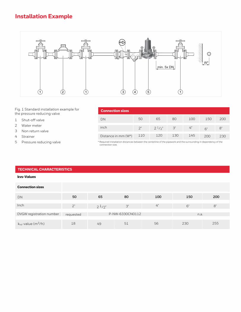
Installation Example
Connection sizes
DN
inch
Distance in mm (W*) 120
* Required installation distances between the centerline of the pipework and the surrounding in dependency of theconnection size.
1 Shut-off valve
2 Water meter
3 Non return valve
4 Strainer
5 Pressure reducing valve
Fig. 1 Standard installation example for the pressure reducing valve
65
110
50
3"
130
80
145
100
200
150
230
200
4" 6" 8"2"
TECHNICAL CHARACTERISTICS
DN
Inch
DVGW registration number
49
65
requested
50
3"
18
80
P-NW-6330CN0112
100
n.a.
150
255
200
4" 6" 8"2"
kvs-Values
51
1 2 1 3 4 5 1
W*min. 5x DN
2 1/2"
kvs-value (m3/h)
Connection sizes
2 1/2"
56 230

Fig. 2 Pressure drop within the valve in dependency of the flow rate and the used connection size (Sizes 50-100)Pressure setting: P1: 8bar, P2: 3bar
Fig. 3 Pressure drop within the valve in dependency of the flow rate and the used connection size (Sizes 150-200)Pressure setting: P1: 8bar, P2: 3bar
D15S-65AD15S-80AD15S-100A
0 10 200 400 60
D15S-50Aflow [m³/h]
0,30
0,40
0,50
0,60
0,00
0,200,10
∆p [bar]
D15S-150AD15S-200A
0 40 20 0 8606 100 120 140 160 180 200 220 240
∆p [bar]
flow [m³/h]
0,30
0,40
0,50
0,60
0,70
0,100,00
0,20
Pressure drop characteristics
DN50
1.4 m3/h 2.4 m3/h 3.6 m3/h 5.6 m3/h 12.7 m3/h 22.6 m3/h
█ ≙ 1m/s flow rate 7 m3/h 12 m3/h 18 m3/h 28 m3/h 63 m3/h 113 m3/h
▲≙ 2m/s flow rate = QN 14 m3/h 24 m3/h 36 m3/h 56 m3/h 127 m3/h 226 m3/h
Flow rate 4m/s flow velocity 28 m3/h 48 m3/h 72 m3/h 112 m3/h 254 m3/h 452 m3/h
● ≙ 10% of standard flow
DN65 DN80 DN100 DN150 DN200

DIMENSIONS
Overview
Connection sizes
Nominal sizes
Weight 30.5kg
Inch
110 135
15065 200DN
Parameter Values
H
L
h
F
14
50
296
230
83
165
2" 3" 4" 6" 8"
290
93
370
185
32
80
310
100
370
200
34.5
100
350
110
370
220
480
143
541
285
600
170
534
340
Note: All dimensions in mm unless stated otherwise.
ORDERING INFORMATION
The following tables contain all the information you need to make an order of an item of your choice. When ordering, please always state the type, the ordering or the part number.
Options
The valve is available in the following sizes: 2", 21/2", 3", 4", 6" and 8".• Standard
- not a ailable
Flanges PN 16, ISO 7005-2, EN 1092-2, face to face length acc. EN558-1
D15S-...A
Ductile cast iron (EN-GJS-400-15 EN 1563), coated with PA (polyamide)
•
H
hF DN
Dimensions
2 1/2"
Housing •
Note:
Note:
... = space holder for connection size
Ordering number example for 21/2" and type A valve: D15S-65A
Product Specification Sheet • EN0H-1049GE23 R0217 • Subject to change

Accessories
Parameter Description Dimension Part No.
EXF125-A Extension flange DN125Adapter flanges DN100 to DN125
Ductile iron, PN16 acc. ISO 7005-2 and EN1092-2.
Overall length with adapter flanges (without bolts)
DN125 L=416mm, DVGW approved, including bolts and nuts.
EXF125-A
Description Dimension
DN50
Technical Specification
Part No.
0904175
DN65 - DN100
DN150 - DN200
0904120
0904139
1
Spare PartsPressure Reducing Valve D06F, from 1997 onwards
Overview
Valve insert complete
DN50 0904176
DN65 - DN100
DN150 - DN200
0904121
0904140
2 Set of seals complete
0 - 10 bar M39M-A10
0 - 16 bar M39M-A16
3 Pressure gauge
Pressure gauge4
D15SPRESSURE REDUCING
VALVE
© 2020 Honeywell International Inc.
For more information,https://honeywellbuildings.inCall: 1-800-103-0339Email: [email protected]
Honeywell HBT India BuildingsUnitech Trade Center, 5th Floor, Sector-43, Block C, Sushant Lok Phase - I,Gurgaon - 122 002
www.honeywell.com


![PORQUE HONEYWELL Patrick Bogaert]. 2 HONEYWELL - CONFIDENTIAL](https://img.pdfslide.us/doc/110x75/5665b4371a28abb57c900f84/porque-honeywell-patrick-bogaert-2-honeywell-confidential.jpg)