Embed Size (px)
Citation preview

D&T Resistant Materials Commercial Production MethodsD & T RESISTANT MATERIALS
CONTENTS
Worksheet

D&T Resistant Materials Ergonomics
1. Knowledge and UnderstandingErgonomics & anthropometrics 6
2. Commercial Production MethodsTemplates and jigs 7a-7b
3. Design ProcessDesign process 10
4. Making in WoodSelecting wood 11a-11dMarking out wood 13Shaping wood – wasting 14a-14fJoining wood 15a-15cJoint cutting instruction sheets 16a-16fWood adhesives 17Mechanical fixings 18a-18bWood finishes 20a-20bTurning wood 21
5. Making in MetalSelecting metals 24a-24bMarking out metal 25Shaping metal – wasting 26a-26eForming metal 27a-27dCasting metal 28a-28bJoining metal 29a-29fHeat treatment 30Metal finishes 31
6. Making in PlasticsSelecting plastics 33Marking out plastics 34Shaping plastics – wasting 35Forming plastics 36a-36cJoining plastics 37Finishing plastics 38
ERGONOMICSEvery well designed product must be easy, comfortable and safe to use. The parts of the product that are touched by humans, e.g. handles, seats, table tops etc. are said to be ergonomically designed.
ERGONOMEWhen a designer is working on large products, such as furniture, they often use a stylised scale drawing or 3D model of the human body called an ergonome.
ANTHROPOMETRIC DATAA designer needs to make sure that the sizes chosen for a design are ergonomically correct. To do this the
Cable Educational Ltd Worksheet 6

D&T Resistant Materials Ergonomics
designer will look up anthropometric data.5th & 95th PercentileTo help tell the difference between the smallest 5% and largest 5%, anthropometric tables use the term percentiles instead of percentages and give three columns of information for each measurement.e.g. For the standing height measurement of adult men 5th percentile - 5% of the population are 1644mm tall, or smaller50th percentile - 50% (half) of the population will be 1753mm tall, or smaller.95th percentile- 95% of the population will be 1861mm tall, or smaller
Measurement Subject 5th
Percentile50th Percentile
95th Percentile
standing height in mm
adult male 1644 1753 1861
adult female
1517 1626 1734
handle diameter in mm
all adults 40 45 52
1. Brief A paragraph explaining the problem you are trying to solve.
2. Analysis Starting to think about the problem. This can be done by thinking about Design factors:
Aesthetics: This is to do with how things look. If a designer wanted to make a product look better they might look at changing the colour, shape, contrast or texture of the object.
Materials: This is to do with what things are made from.A designer has to think carefully about what things are made from. The material used should not make the product too expensive. The materials should also be right for the product. (A lamp shape should not be made from a material which can go on fire).
Ergonomics: This is how the product fits the human body.
Cable Educational Ltd Worksheet 6
5% 5%
Smallest Tallest
We only design for people in this range

D&T Resistant Materials Ergonomics
The designer has to think about making products which are the right shape for the human body. Making sure tables are not too high, seats are wide enough, computer mice buttons are in the right place etc. Anthropometrics is about gathering the measurements of the human body needed in ergonomics. Designers sometimes use small scale plastic or wooden figure called an ergonome to help check that products are the right size.
Safety: This is to do with keeping the person who will use your product safe.A designer has to think about no sharp edges, not using poisonous materials, not burning anyone, not making products which could fall onto the user. Most products you buy in a shop need to meet British Safety Standards.
3. Specification A list of what your product should do
4. Research Finding out important information which will help you to design. Sizes of CD’s, Ergonomics etc. You can ask lots of people what they think is important in a survey, this is called market research.
5. Ideas Coming up with ideas for what to make. You can use different ways of coming up with ideas (take a pencil for a walk, brainstorming, morphological analysis, using a theme).
6. Development Fine tuning your ideas to end up with one idea.
7. Modelling Making a model to check the idea looks ok or to let other people see your idea. (Usually not made full size, from cheap materials.)
8. Solution A finished drawing of the idea you are going to make.
9. Planning Producing a Working Drawing, and a step by step guide
showing how you are going to make your idea.
10.ManufactureMaking your project. You will make just one item, but in industry you would have to make lots. This is called mass production.
11.Evaluation Checking with the specification to see if you have solved the problem written down in your brief.
SELECTING WOODTypes of WoodThere are three types of wood, Softwood, Hardwood and Manufactured Boards.
SoftwoodConiferous trees (trees that keep their needle-like leaves throughout the year) provide softwood. They can grow quickly with straight trunks. They are often grown in plantations and are replaced when they are cut down. The wood is quite cheap and is used in the building industry for windows and doors etc. When the trunk is converted the waste is used for making paper and card.
Choosing SoftwoodNAME PROPERTIES USES COST
ScotsPine(Deal)
Straight grained, butknotty, quite strongand easy to work
Building construction.When used outside itneeds protection.Takes paint well.
Low
Cable Educational Ltd Worksheet 6

D&T Resistant Materials Ergonomics
ParanaPine
Straight grained withfew knots, quitestrong and durable,warps easily
High quality interiorconstruction andfurniture
High
Spruce(white-wood)
Quite strong, withsmall knots, resistantto splitting but notdurable
Fitted furniture, e.g.kitchen cabinets. Low
CedarStraight grained that isknot free. Very light inweight. Very durable,inside and outside.Quite soft.
Used outside forshed constructionand quality fencing.
High
HardwoodDeciduous trees (trees that lose their large leaves every winter) provide hardwood. They grow slowly and sometimes have twisted trunks. They are often not replaced when cut down. The wood is costly and is used for fine furniture and wooden toys, etc.
Note: The difference between softwood and hardwood is a biological difference, not one of softness and hardness. The softest wood is Balsa - it is a hardwood!
Choosing Hardwood
NAME PROPERTIES USES COST
Ash
Light in colour, flexi-ble and tough, steambends well, varnisheswell.
Tool handles, cricketbat handles, ladders,veneers.
Med
Beech
Mid-brown colour,hard, strong andtough, tends to warp,steam bends well.
High quality furniture,toys, tool handles,veneers
Med
Oak
Light brown, hard,tough, heavy and du-rable outside. Getsharder with age.
High quality furniture, garden furni-ture, boat building,veneers
High
Mahogany
Red in colour, mediumweight, quite strong,durable inside, warpseasily
High quality furniture, shop furniture,boat fittings,veneers.
High
Manufactured BoardsThese are made from the waste wood left over from conversion. They use thin sheets (plywood), small blocks (blockboard), wood chips (chipboard) and wood fibres (fibreboard). They are generally cheaper than solid wood and can be made into large sheets that do not warp or twist easily.
PlywoodMade from thin sheets of wood (veneers), glued together with the grain direction at 90° to the one next to it. They always have an odd number of layers 3,5,7 etc. to reduce warping
Medium Density Fibreboard (MDF)
Made from fine wood fibres, compressed and
Cable Educational Ltd Worksheet 6

D&T Resistant Materials Ergonomics
glued together. When in use it is normally covered by a plastic coating or hardwood veneer.
Blockboard
Strips of softwood are glued together and then sandwiched between two hardwood veneers. The
edges look rough and are often covered with a thin hardwood strip
ChipboardMade by compressing and gluing small chips of waste wood. When in use it is normally covered by a plastic coating or hardwood veneer.
HardboardMade by compressing and gluing pulped wood. It is smooth on one side and rough on the other.
1. What sort of trees do hardwoods and softwoods come from
2. What are manufactured boards made from?
4. Which softwood might you choose to make a dog kennel from?
5. Which hardwood might you choose to make a child’s toy truck?
6. Explain how plywood is constructed.7. Which manufactured board might you choose
to make a long shelf for heavy books?8. What is the environmental advantage of
making and using chipboard?
MARKING OUT WOODPositioningWhen you wish to cut a shape from a manufactured board, you should mark it out in one corner in order
to
create as little waste as possible.
e.g. A circular base for a table lamp is required.
Cable Educational Ltd Worksheet 6
NAME PROPERTIES USES COST
PlywoodStrong in alldirections, quite stablebut can warp. A water-proof ply is available.
Tabletops, worktopsdoor fronts, drawerbottoms, small boats(waterproof ply)
Med
MDFDoes not warp easily,cuts and planes wellwithout splitting,needs a finish.
Tabletops, worktops,veneered furniture,clock cases. Med
BlockboardDoes not warp easily.Very strong, rigid andrather heavy. Edgefinishing is difficult.
High quality furniture, stage flooring,fire doors.
High
Chipboard
Heavy, can warpeasily, joining piecestogether is not easy,needs a finish.
Cheap plasticcoated furniture,roofing boards,partitions
Low
HardboardNot very strong,warps easily, needs afinish.
Door panels, cheapdrawer bottoms,cabinet backs.
Low
Incorrect marking out, it is difficult to cut out and a lot of the board
will be wasted.
Correct marking out, it is easy to cut out and
wastes very little.

D&T Resistant Materials Ergonomics
When you measure across the wood you should always start the measurement from a face-side or face-edge. Also when you use a try-square to draw lines across the wood you should hold the square so that the handle is always touching a face-side or face-edge.
The handle of the trysquare is touching the face-edge
If you need to draw a line along the piece of wood, the most accurate way is to use a marking gauge. The gauge should run along a face- edge. This will produce a scratched line which may need a pencil point run along it to make it easy to see. A scratched line cannot be rubbed out accidentally.
KEY WORDS Face-side: Face-edge: Marking gauge: Dividers: Marking knife
1. For accurate marking out of lines across a piece of wood show how the try-square should be placed.
2. What tool would you use to mark a line parallel to an edge?
3. Why is a scratched line more useful than a pencil line?
4. How can you tell the difference between a pair of dividers and a pair of compasses?
5. Which tool can you use to scratch an accurate straight line?
Cable Educational Ltd Worksheet 6
To mark out circles and arcs use a pair of dividers, (they have a sharp point on both legs).
For accurate marking out you need to use a marking knife instead of a pencil. The blade is a lot thinner than a pencil lead and it produces a scratched line.

D&T Resistant Materials Ergonomics
SHAPING WOOD – WASTINGWasting is the term given to any of the cutting processes that produce waste material.
Sawing Hand-held saw blades are made from Tool Steel alloyed with Vanadium and Molybdenum, to give toughness and long lasting sharpness.
The saw cutting action - each tooth cuts a little deeper as the saw moves forward.
Each tooth of the saw is alternately bent to the right and the left of centre. This is to stop the blade from jamming in the cut. The width of the cut is called the kerf.
Wood must be well supported when being sawn.
When sawing small pieces of wood use a bench hook (also known as a sawing board). The bench hook should be held in the bench vice to stop it moving and the wood is held in place by hand.
When sawing long pieces of wood, use a pair of trestles (also known as sawing horses). The wood can be held by G-clamps.
Panel SawA large saw used for making straight cuts. Saws with large teeth are for cutting along the grain (Rip Saw). Saws with smaller teeth are for cutting across the grain (Cross-cut Saw).
Tenon SawA medium length saw that has a brass or steel back to keep the blade rigid. It is used for making straight cuts and especially designed for joint cutting. A smaller version is known as a Dove-tail Saw.
Coping SawA thin bladed saw used for making curved cuts. The blade can be set at any angle so that long cuts can be made without the frame getting in the way.
Purchasing SawsSaws can be bought with different size teeth. The size of teeth is measured by the number of teeth there are in a one inch length along the blade. This is known as ‘Teeth per Inch’ or ‘TPI’. The more teeth per inch, the smaller the teeth.
KEY WORDS Kerf: Bench hook: Trestle:
1. Explain the term ‘kerf’ using notes and a diagram.
2. How would you support a small piece of wood while you are cutting across it? (answer with a diagram).
3. Show how you would support a long length of wood for sawing.
4. Which saw would you choose to cut a finger joint and why?
5. Which saw would you choose to cut a large sheet of thick plywood in half and why?
6. You need to cut the shape of a number ‘2‘ from a small sheet of thin MDF, which saw would you use?
7. What is the meaning of the term ‘TPI’?
Cable Educational Ltd Worksheet 6
Use the end of the stop to guide the saw

D&T Resistant Materials Ergonomics
8. You are cutting a curve along a thin strip of pine, the frame of the saw gets in the way, how can you complete the saw cut?
SHAPING WOOD – PLANINGPlanes are used for removing waste wood and smoothing the surface before applying a finish. A correctly planed surface is smoother than can be obtained by using glasspaper. There are many different planes designed to cope with different situations. The most common planes are the ‘Jack Plane’ and ‘Smoothing Plane’. They look alike but the smoothing plane is smaller.
The Jack Plane and Smoothing Plane
Checking and adjusting the planeThe plane should be checked each time that it is taken from the store. The blade cutting edge should be parallel to the base of the plane and be showing no more than 0.5mm. Shavings should be tissue thin for a smooth finish.
If the blade is not parallel to the base and one corner is further out than the other is, it can be adjusted by moving the level adjustment lever to correct it.
Direction of movement to make the blade level
If the blade is not showing or it is out too far then the height adjustment screw needs to be turned. It is turned clockwise to make the blade move out and anticlockwise to make the blade move in.
Note: When the direction of turn is changed there is quite a lot of slack to make up before the blade moves.
Height adjustment screw
If the wood is not planed in the correct direction the surface will end up
very rough. To check the direction, the side of the piece of wood should be looked at, not the top surface being planed. Look at the direction the grain is approaching the top surface and then plane in the same direction.
If the grain is parallel to the edge then it is possible to plane in either direction and gain a smooth finish.
Cable Educational Ltd Worksheet 6
D&T Resistant Materials Ergonomics
Planing procedureAt the start of the stroke the front should be held down firmly on the end of the piece of wood with the blade clear of the wood. The other hand should be used to push the plane along the surface. When the blade has passed over the other end of the piece of wood the plane should be lifted clear and returned to its starting position. If the plane is not lifted clear the results of the planing cannot be seen for checking.
Planing end-grainIf the plane is taken over the end of an end-grain surface the wood will split. To stop this, always lift the plane early just beyond the centre and then plane in the other direction and lift early.
Another method, suitable for narrow pieces, is to
clamp a piece of waste wood with an angled (chamfered) corner to the side and plane the full width. The waste wood will hold the grain of the work together and stop it splitting. The chamfered corner of the waste wood is resistant to splitting (a). A third method is to chamfer one or both corners of the wood to be planed (b).
KEY WORDS Jack plane: Smoothing plane: Shavings
1. Name the two most common planes to found in a workshop.
2. Why does a plane need to be checked when it taken from store to be used?
3. Which adjusting device would you use if the blade was out too far?
4. Which adjusting device would you use if the blade was not parallel to the base?
5. What is the recommended maximum amount of the blade that should be showing?
6. How can you tell which direction to plane a piece of wood to get a smooth finish?
7. If the grain is mainly parallel to the edges, in which direction can you plane it?
8. What happens if you try to plane end-grain in the same way as side-grain?
9. How can you overcome the problems involved in planing end-grain on a wide board?
10. What is the recommended method of planing the end-grain of a narrow piece of wood?
Cable Educational Ltd Worksheet 6

D&T Resistant Materials Ergonomics
SHAPING WOOD – CHISELLING
Chisels are used for chopping away waste wood when cutting a joint and for paring small amounts of wood away when fitting the two halves of the joint together accurately.
Chopping, using a mallet Paring by hand
Firmer chiselThe firmer chisel, like most chisels, has a blade made from tool steel and a handle made from Ash or polycarbonate and is designed for chopping away waste wood. The ferrule is a brass ring that stops a wooden handle from splitting.
Bevel-edged chiselThe blade is thinner at the edges than a firmer chisel and is used for paring and for cleaning out corners.
Safety Note: when paring always keep both hands behind the blade of the chisel to avoid cutting yourself.
Cable Educational Ltd Worksheet 6

D&T Resistant Materials Ergonomics
Mortise chiselThe mortise chisel is used for cutting the hole (the mortise) for a mortise and tenon joint. It is designed to withstand being hit hard with a mallet. The leather washer helps to absorb some of the shock and the steel ferrule stops the handle from splitting at the end.
GougeThe gouge has a curved blade and is used to cut shallow depressions in wood.
An end-on view of a gouge in use
KEY WORDS Firmer: Mortise: Bevel: Gouge: Paring
1. Make a labelled sketch of a firmer chisel.
2. From what materials are chisel handles made?
3. What is the purpose of a ferrule on the handle of a chisel?
4. What is the advantage of the bevelled edges on a chisel?
5. State a safety rule that you should observe when using a chisel.
6. From what material are chisel blades made?
7. What is a mortise chisel used for?
8. What is the purpose of the leather washer found on a mortise chisel?
9. What is the difference between a gouge and a firmer chisel?
10. What is a gouge used for?
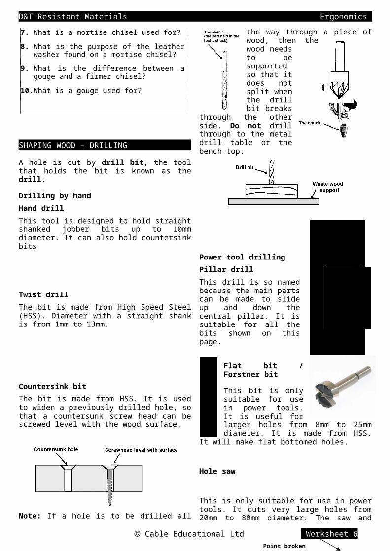
SHAPING WOOD – DRILLINGA hole is cut by drill bit, the tool that holds the bit is known as the drill.
Drilling by handHand drillThis tool is designed to hold straight shanked jobber bits up to 10mm diameter. It can also hold countersink bits
Twist drillThe bit is made from High Speed Steel (HSS). Diameter with a straight shank is from 1mm to 13mm.
Countersink bitThe bit is made from HSS. It is used to widen a previously drilled hole, so that a countersunk screw head can be screwed level with the wood surface.
Note: If a hole is to be drilled all the way through a piece of wood, then the wood needs to be supported so that it does not split when the drill bit breaks through the other side. Do not drill through to the metal drill table or the bench top.
Cable Educational Ltd Worksheet 6
D&T Resistant Materials Ergonomics
Power tool drillingPillar drillThis drill is so named because the main parts can be made to slide up and down the central pillar. It is suitable for all the bits shown on this page.
Flat bit / Forstner bit
This bit is only suitable for use in power tools. It is useful for larger holes from 8mm to 25mm diameter. It is made from HSS. It will make flat bottomed holes.
Hole saw
This is only suitable for use in power tools. It cuts very large holes from 20mm to 80mm diameter. The saw and guide bit are made from HSS.
Note: When using a flatbit or hole saw, only cut the hole until the point of the flatbit, or the guide bit of the hole saw, break through the other side. Then turn the wood over and using the break-through hole as a guide, cut the second half of the hole. This method will stop the wood from splitting.
1. What is the chuck on a drill used for?
2. What are good quality drill bits made from?
3. Draw a diagram showing a countersunk hole and what it is used for.
4. How do you prevent wood from splitting when a hole is drilled all the way through it with a twist bit? Use a diagram in your answer.
5. Why is a pillar drill so called?
6. When would you use a flat bit instead of a twist bit?
7. When using a hole saw, how would you prevent the wood from splitting?
8. Which bit would you choose to use if you had to drill a 35mm hole and why?
FABRICATION - WOOD JOINTSThe word fabricate means to join together.
Most wooden products are held together with adhesive. Adhesive works very well when the edge of a piece of wood is being glued to the edge of another piece of wood (side-grain to side-grain). A solid wood table top is made this way.
Rubbed jointAdhesive is put between the two edges. They are then rubbed together to spread the adhesive evenly. The boards are lined up and held together with sash cramps
If, however, you are making a framework or box and need to join end-grain to side-grain, adhesive on its own will be too weak. By cutting joints, side-grain surfaces on one piece of wood can be made to come in contact with side-grain surfaces on the
other piece of wood. The side-grain to side-grain contact means that the adhesive will now be stronger.
Butt jointThis is a very weak joint unless it is strengthened with pins or screws
Comb or Finger joint
Side-grain to side-grain contact for
Cable Educational Ltd Worksheet 6
Point broken though
D&T Resistant Materials Ergonomics
extra strength
The joint is also mechanically stronger. Any force in the direction of the arrow will not push the joint apart even if there is no adhesive holding it together.
Framework joints
Corner joints
Corner HalvingUsed for lightweight frames and frames that are to be covered by boarding e.g. a door. The joint is quick and easy to cut
Corner BridleUsed for heavier, stronger frames because it has a large area of contact and cannot be twisted apart unlike the halving joint. The joint is quite difficult to cut
DowelUsed for lightweight frames. The holes are difficult to line up unless a doweling jig is used.
Tee joints
Tee Halving
Used for lightweight frames, especially those to be covered with boarding. The joint is quick and easy to cut.
Cable Educational Ltd Worksheet 6

Dovetail HalvingA stronger version of the Tee Halving. Used for medium weight frameworks.
Mortise and TenonA strong joint that is quite difficult to cut and fit by hand. Used for heavier frameworks and uncovered frameworks.
Crossover joints
In some frameworks pieces of wood have to cross one another
Cross HalvingThis joint is quite strong and resists twisting. This is the only crossover joint that is flush (flat) on both sides.
Box joints
Used for general furniture construction.
Butt jointA weak joint on its own. The example shown has a reinforcing wooden strip glued to the inside. A quick and easy joint to make. This joint can also be used with manufactured board.
Another way of reinforcing the joint is to use pins. For greatest strength the pins are best used in pairs and angled towards each other. This is known as dovetail pinning.
Lap jointAlthough stronger than a butt joint, the lap joint is best when reinforced with dovetail pinning or screws.
Cable Educational Ltd Worksheet 15a

Mitre jointThis joint although weak, has the advantage of not showing any end grain, it looks neat and clean.
To reinforce the joint, grooves can be cut into the corner and and then triangular pieces of thin wood are glued into the grooves.
Dowel jointThis looks like a butt joint but is a lot stronger. It is difficult to line up the holes without using a dowelling jig. This joint can also be used with manufactured board.
Dovetail jointA very strong joint. Used for drawers where the front is pulled every time the drawer is used. It is difficult to mark out and cut. This joint is also used as a design feature.
Comb or Finger jointA strong joint (a lot of side-grain to side-grain contact). The joint can be considered as a design feature because if it is well fitted it adds to the good looks of the furniture.
Housing joints
Through HousingUsed for fitting shelves into cabinets or units and partitions in boxes.
Dovetail HousingA stronger form of a through housing. The groove is best cut with an electric router.
Stopped HousingCan be either a plain or dovetail housing. It has the advantage of not showing the joint at the front
1. In what way should wood be glued together to get maximum strength?
2. In what ways is a cut joint stronger than a butt joint?
3. Name and sketch two joints suitable for the corner of a framework.
4. Name and sketch two joints suitable for tee sections of a framework.
5. Show how a weak butt joint can be reinforced.
6. Show how a mitre joint can be reinforced.
7. What is the main problem to overcome when making a dowel joint?
8. Name and sketch a joint that is suitable for joining a drawer front to its sides.
9. How can you join two lengths of wood that cross over each other?
10. Name and sketch a joint suitable for holding a shelf In place.
Cable Educational Ltd Worksheet 15b

CUTTING A COMB JOINT
1. Using a try-square and marking knife or pencil, mark out the shoulder line all the way round one end of A and B.
2. Using a marking gauge, mark out the comb ‘teeth’. Set the gauge gap to 1/3rd the width of the wood. Check that both pieces match.
3. Put squiggle marks with a pencil upon the parts to be cut out (the waste).
4. Using a tenon saw, cut down on the waste side of each ‘tooth’.
5. On part A use a tenon saw to cut on the waste side of the shoulder line.
6. On part B use a tenon saw to cut diagonally across the recess.
7. Then cut diagonally across the triangular waste in the recess.
8. Use a mallet and chisel to chop the remaining waste down to the shoulder line.
9. Using a bevel-edged chisel pare down all the cut surfaces to the lines. Then try to fit the joint together, do not force the parts together. If they won’t fit, check carefully to see which parts are too large and pare a small amount off them, then test
again. Keep paring and testing until the joint fits perfectly.
The overlapping parts can be planed flush once the joint has been
glued together.
Cable Educational Ltd Worksheet 15c
This dimension should be the thickness of the wood plus 1mm.

CUTTING A MORTISE & TENON JOINT
1. Using a try-square and marking knife or pencil, mark out the ends of the mortise on both sides of the wood.
2. Using a mortise gauge mark out the sides of the mortise on both sides of the wood.
3. Hold the wood firmly on the bench top with a G-clamp. Use a mortise chisel and mallet to chop out about a 3mm depth of wood from the ends of the mortise.
Always have the flat side of the chisel blade facing the end of the mortise, this gives neat, clean ends to the hole.
4. Place the chisel 3mm back from the last cut and hit down to a depth of about 3mm and lever out the waste. Repeat this along the mortise. Continue taking out layers until you reach half the depth, then turn the wood over and repeat steps 3 and 4.
5. Using a try-square and marking knife or pencil, mark out the shoulder lines for the tenon all the way round the wood. The line should be the thickness of the wood plus 1mm from the end.
6. Use the mortise gauge, set as it was for the mortise. Mark parallel lines up both sides and across the top of the wood
7. Angle the wood in a vice and saw to the shoulder line. Angle the other way and repeat.
8. Place the wood upright in the vice and saw down to the shoulder line. This method helps to stop the saw straying from the lines.
9. Hold the wood horizontally on a sawing board and saw off the waste to the shoulder lines with a tenon saw. Place the blade on the waste side of the line.
10. Gently try fitting the joint together. If you force it the mortise wood will split. If the tenon is too large then pare a small amount off it with a chisel.
Note: Fitting can take some time.
The part of the tenon poking out can be planed flush when the joint is glued.
CUTTING A HOUSING JOINT Cable Educational Ltd Worksheet 16a

1. Using a try-square and marking knife or pencil, mark out the position of the housing. The lines should be the same distance apart as the thickness of the wood going into the joint.
2. Using a marking gauge scratch the line that shows the bottom of the housing groove on both edges.
3. Clamp a piece of straight edged waste wood in line with one of the groove lines and using the waste wood as guide, saw down to the bottom of the housing groove. Repeat for the other line.
4. Edge clamp the wood and use a hand router to cut away the centre section.
Note: For a clean finish only try and cut up to 1mm at a time. Lower the blade 1mm between each pass.
5. The joint should now fit together.
Stopped Housing JointTo cut a stopped housing joint the end of the groove needs to be cut out like a mortise, so that the groove lines can be sawn without the saw going across the whole width of the wood.
A) Using a mortise chisel and a mallet, chop out the last 25mm of the groove, to the full depth.
B) Use a piece of waste wood as shown in (3) to guide the saw. The hole allows the saw to move a short distance backward and forward.
C) Use a hand router as in (4) to complete the groove
D) The shelf or divider will need to have the front corner cut away so that it fits flush with the front of the housing. A marking gauge can be used to mark out all the lines for this.
Cable Educational Ltd Worksheet 16b

CUTTING A CORNER HALVING JOINT Corner Halving
1. Using a try-square and marking knife or pencil, mark out the shoulder line on one side and both edges of both pieces of wood.
This dimension should be the width of the wood plus 1mm.
2. Using a marking gauge, mark out a half-thickness line, up the edges and across the end of the joint.
3. Angle the wood in a vice and saw to the shoulder line. Angle the other way and repeat.
4. Place the wood upright in the vice and saw down to the shoulder line. This method helps to stop the saw straying from the lines.
5. Hold the wood horizontally on a sawing board and using a tenon saw, saw off the waste. The saw blade should be placed on the waste side of the shoulder line.
7. The overlapping parts can be planed flush after the joint has been glued together.
Cable Educational Ltd Worksheet 16c

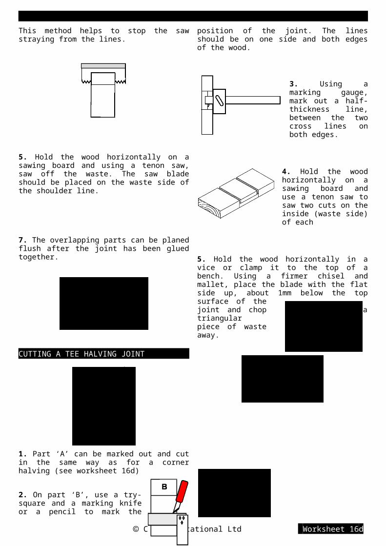
CUTTING A TEE HALVING JOINT
1. Part ‘A’ can be marked out and cut in the same way as for a corner halving (see worksheet 16d)
2. On part ‘B’, use a try-square and a marking knife or a pencil to mark the position of the joint. The lines should be on one side and both edges of the wood.
3. Using a marking gauge, mark out a half-thickness line, between the two cross lines on both edges.
4. Hold the wood horizontally on a sawing board and use a tenon saw to saw two cuts on the inside (waste side) of each
5. Hold the wood horizontally in a vice or clamp it to the top of a bench. Using a firmer chisel and mallet, place the blade with the flat side up, about 1mm below the top surface of the joint and chop a triangular piece of waste away.
6. Repeat the above until the blade sits in the halfway groove and a slope is created.
7. Turn the wood around and repeat steps 5 and 6.
8. Turn the chisel the other way up and then chop the top off the triangular waste. Repeat this until the joint has a level base.
9. The overlapping part can be planed flush after the joint has been glued together.
Cross Halving JointCutting the cross halving is the same as cutting part B twice.
When fitting, the sides of the recess may need paring with a chisel to help the joint fit.
Cable Educational Ltd Worksheet 16d

CUTTING A DOWELLING JOINT
The most difficult part of cutting a dowel joint is lining up the holes. This cannot be done by marking out with a ruler and pencil. The natural inaccuracy of marking out will mean the holes are more likely to be out of line than in line. It is essential that a Dowelling Jig is used. Jigs for wide boards are very expensive and are not likely to be found in school, but making your own jig is not difficult.
A school-made Dowelling JigBoth parts are mild steel
strip 15x3mm cross section
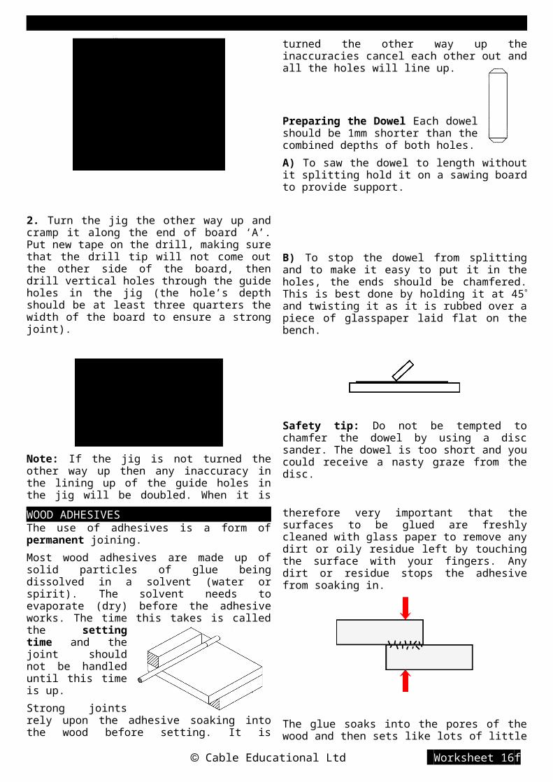
1. Cramp the jig to board ‘B’ with the long leg of the end plate running down the edge of the board. Drill vertical holes through the guide holes in the jig. Hint: to ensure that each hole is the same depth, wrap a piece of adhesive tape around the drill bit and stop drilling when the bottom edge of the tape touches the surface of the jig.
2. Turn the jig the other way up and cramp it along the end of board ‘A’. Put new tape on the drill, making sure that the drill tip will not come out the other side of the board, then drill vertical holes through the guide holes in the jig (the hole’s depth should be at least three quarters the width of the board to ensure a strong joint).
Note: If the jig is not turned the other way up then any inaccuracy in the lining up of the guide holes in the jig will be doubled. When it is turned the other way up the inaccuracies cancel each other out and all the holes will line up.
Preparing the Dowel Each dowel should be 1mm shorter than the combined depths of both holes.
A) To saw the dowel to length without it splitting hold it on a sawing board to provide support.
B) To stop the dowel from splitting and to make it easy to put it in the holes, the ends should be chamfered. This is best done by holding it at 45 and twisting it as it is rubbed over a piece of glasspaper laid flat on the bench.
Safety tip: Do not be tempted to chamfer the dowel by using a disc sander. The dowel is too short and you could receive a nasty graze from the disc.
Cable Educational Ltd Worksheet 16e
Holes marked out and drilled to the same diameter as the dowel before joining to the end plate.

WOOD ADHESIVESThe use of adhesives is a form of permanent joining.
Most wood adhesives are made up of solid particles of glue being dissolved in a solvent (water or spirit). The solvent needs to evaporate (dry) before the adhesive works. The time this takes is called the setting time and the joint should not be handled until this time is up.
Strong joints rely upon the adhesive soaking into the wood before setting. It is therefore very important that the surfaces to be glued are freshly cleaned with glass paper to remove any dirt or oily residue left by touching the surface with your fingers. Any dirt or residue stops the adhesive from soaking in.
The glue soaks into the pores of the wood and then sets like lots of little fingers grabbing onto the wood on both sides. Using a cramp to hold the two halves of a joint together firmly helps to force glue into the pores of the wood. Cramping also holds the joint still while the glue is setting.
When the joint is cramped excess glue should squeeze out of the joint. If it doesn’t, not enough glue has been used. The excess glue should be wiped away with a damp cloth quickly, before it sets.
The squeezed out glue stains the wood white and the stain will show under any clear varnish that might be put on later.
Tip: Varnish the wood before you glue the parts together, the glue will not stain varnished wood.
Warning: Do not varnish the joint contact surfaces because the varnish will stop the glue soaking into the wood and result in a very weak joint.
KEY WORDS Adhesive: Cramp: Setting time: Toxic:
Gap fillingMost wood glues do not fill gaps well because they soak into the wood. If a joint is badly cut and leaves a gap, glue the joint in the normal way and let it set. Now saw some waste wood of the same type and colour and collect the sawdust. Mix the sawdust with new glue to create a paste. The paste can now be forced into the gap so that it fills it completely and is sticking out a little. When the paste has set it can be sanded down flush with the wood surface.
Gap to be filled withsawdust and glue paste
Contact glueThis is useful for joints where no sliding together is required e.g. lap joints. The glue is applied to both surfaces and they must be left apart for at least ten minutes (until the glue looks dry) to allow the spirit to evaporate. The joints can then be lined up and pushed together.
ADHESIVE SETTINGTIME COMMENTS
PVA(polyvinylacetate)
1 hourNon-toxic, white, water-based gluefor general use. Normally waterresistant when set.
SyntheticResin
(Cascamite)
2 - 6hours
Non-toxic, white, water-based glue.Used when extra strength isimportant. Waterproof when set.
ContactAdhesive(Evostick)
instant
Highly toxic, brown, spirit based,waterproof glue. Used on nonporous surfaces. Must be used ina well ventilated area. DO NOTsniff the glue.
Glue sticks 15seconds
Non-toxic plastic.Not very strong.Only useful for spot gluing. Excessglue difficult to clear away.
1. What type of jointing are adhesives used for?
2. Explain the term ‘setting time’.
3. How is an adhesive made up?
4. How does a water-based adhesive work on wood?
5. What preparations should be made before using an adhesive?
6. What is the purpose of cramping a joint together?
7. How can you avoid a glue stain showing through a clear varnish finish?
8. How can you use glue to fill a gap in a badly cut joint?
9. Which adhesive would you choose for holding together a garden seat and why would you
Cable Educational Ltd Worksheet 16f

choose it? 10. What precaution should you take when using contact adhesive?
MECHANICAL FIXINGS FOR WOODNails, pins and screws, used without glue, provide a semi-permanent method of jointing.
Nails and PinsPanel PinA pin is a small nail, made from rigid mild steel wire. Pins are normally used with adhesive, to hold the joint together while the adhesive is setting.
Pin PunchA pin punch is used with a hammer to drive the head of the pin below the wood surface. The hole above the pin head can then be filled with a wood filler so that the pin cannot be seen.
Round Wire NailMade from galvanised mild steel the wire nail is used for exterior heavy construction. The nail head cannot be hidden. Nails are normally used without any adhesive and rely upon friction between the nail shaft and the surrounding wood to hold them in.
Oval BradThe shaft is oval in shape so that when correctly used it is less likely to split the wood. The oval brad can be hidden by using the same method as hiding a pin.
Split caused by placing the nail too close to the end of the wood.
Nail placed at least nine times its diameter from the end of the wood to avoid splitting.
Oval Brad placed with the oval length in line with the grain of the wood to avoid splitting.
Dovetail Pinning
Pins and nails driven in at an angle are less likely to pull out in use. This is known as Dovetail pinning.
Safety hintSmall pins are difficult to hold without the danger of hitting your
fingers with the hammer. Push the pin through a piece of card and hold the card well away from the pin. Once the pin is held in the wood the card can be torn away.
ScrewsCountersunk Head ScrewMade from mild steel or brass. Used when the head needs to be flush with the surface of the wood. The screw can be slot-head for flat blade screwdrivers or crosshead for pozidrive screwdrivers.
Roundhead ScrewCommonly in brass or mild steel covered in black lacquer or chromium plate. Used for extra strength and when the head can stick out from the surface of the wood.
Chipboard Screw
Especially designed, with two spirals, for use on
chipboard so that it does not pull out easily. It is now very popular for general use because it requires only half the number of turns of the
Cable Educational Ltd Worksheet 16g
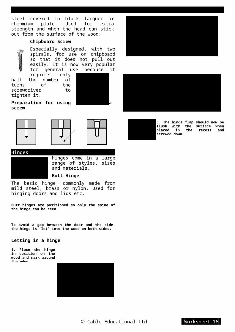
A) Drill a pilot hole of smaller diameter than the thread
B) drill a clearance hole of larger diameter than the thread in the joining wood only
C) If required countersink the clearance hole.
screwdriver to tighten it.
Preparation for using a screw
HingesHinges come in a large range of styles, sizes and materials.
Butt HingeThe basic hinge, commonly made from
mild steel, brass or nylon. Used for hinging doors and lids etc.
Butt hinges are positioned so only the spine of the hinge can be seen.
To avoid a gap between the door and the side, the hinge is ‘let’ into the wood on both sides.
Letting in a hinge
5. The hinge flap should now be flush with the surface when placed in the recess and screwed down.
Cable Educational Ltd Worksheet 16h
1. Place the hinge in position on the wood and mark around the edge.

Knock Down Joints (KD Joints)KD joints are non-permanent and are used for flat-pack furniture that is designed to be put together by the purchaser.
Plastic Modesty BlockThe block is used without glue.
Brass or plasticdowel
The bolt screws into a threaded hole in the dowel
Bolt & Cross DowelCross dowel placed
in drilled hole
KEY WORDS Oval Brad: Countersunk: Butt hinge
1. What holds a pin or nail in place?
2. What is a nail made from?
3. Describe how the heads of pins can be ‘hidden’.
4. How can you prevent nailed wood from splitting?
5. Sketch a claw hammer. What are the two jobs it is designed for?
6. Show how you can hammer in small pins safely?
7. What is the difference between a chipboard screw and a conventional wood screw?
8. Illustrate the stages of preparing a screwed joint.
9. Show how you can prevent a hinged box lid from having a gap between itself and the box when it is shut.
10. What does the term KD joint stand for?
WOOD FINISHESWood has a finish applied for the following reasons: To stop the wood from absorbing moisture, so
that it is less likely to become stained and also less likely to warp.
To protect against rot and insect attack. To improve the appearance of the wood’s
surface.
PreparationThe wood must be made clean and smooth before the finish is applied.
PlaningA smoothing plane with
the blade set to cut tissue thin shavings will give the smoothest finish.
Note: Do not use glass paper after planing because this will roughen the surface again.
Glass-papering (sanding)Glass paper comes in various grades of coarseness:
A coarse paper should be used first, then a medium paper and finally a fine paper.
Always sand in the direction of the grain
Cable Educational Ltd Worksheet 16i
2. Use a marking gauge to scratch a line showing the thickness of the hinge flap.
3. Using a firmer chisel and mallet chop around the outline to the depth of the flap
4. Chop out the waste and pare the bottom level.
The glass paper should be wrapped around a sanding block. A proper block is made of cork or has a cork layer stuck to the bottom, cork is a soft springy wood and can help stop the glass paper wearing away too quickly. However, a piece of waste wood can be used instead.Note: Always sand backwards and forwards in the direction of the grain. Any sideways or circular movement will put deep scratches in the wood that are difficult to remove.If you are using an electric, hand held sander, move the whole machine only in the direction of the grain.
PreservativeWood used outside or in damp conditions is likely to rot unless preservative is applied. Wood can be purchased that has had preservative forced into it under pressure (Tanalising). The preservative will last the lifetime of the wood. If untreated wood is used, it can have preservative painted or sprayed onto it, so that it soaks in to the surface. The preservative can be oil based (Creosote) or spirit based. This sort of preservative needs to be replaced every few years because rain gradually washes it out of the wood.
StainStain (colouring) is used to change the colour of light woods to make them more interesting or to blend in with darker woods. It does not hide the grain. Stain is normally applied by rubbing it onto the surface with a soft clean cloth. Stain will not protect the wood so needs a finish on top. It is possible to buy a ‘combined stain with varnish’, this can give a very tough water resistant finish, for use inside and outside.
Apply the stain in small circular movements to even out the colour.
VarnishPlastic based clear varnishes (polyurethane and acrylic) are sold in:
Matt finish - non shinySatin finish - slightly shinyGloss finish - very shiny
A clear varnish allows the pattern of wood grain to show through and will normally darken the wood, giving it a deep, interesting colour. It is also water and heat resistant.The varnish can be applied with a brush (brush in line with the grain for the best finish). At least two coats are required.
i) Apply the first coat thinly and let it set fully. This coat soaks into the pores of the wood and then sets. The wood is now sealed.
ii) Use a fine grade of glass paper to lightly sand the surface because the first coat tends to make the surface rough as it sets.
iii)Apply the second coat also thinly, check for any runs or drips and let it set to a smooth finish.
Note: Varnish should not be applied to oily woods such as teak because after a short time it will flake off.
Cable Educational Ltd Worksheet 16j

WaxSilicone wax gives a medium gloss finish. Like varnish, it allows the grain of the wood to show through. Wax must only be applied on sealed wood, otherwise it soaks in and never shines.
i) Apply a coat of cellulose sanding sealer (this sets in five minutes if applied thinly).
ii) Use a clean cloth to rub a thin coating of wax onto the surface.
iii) Use a clean soft cloth to buff the wax to a shine. Add at least another two coats of wax and buff each time.
OilCooking oil (vegetable) or special teak oil can both be used to give a water and heat resistant, satin finish. An oil finish does not crack or peel off.
Oil can be applied with a clean cloth directly onto the smooth, unsealed surface of the wood. Five to ten minutes should be allowed between coats to allow each coat to soak into the wood. Three coats is normally sufficient.
To maintain a good finish oil should be applied regularly about every six months.
Oily woods are best finished with teak oil, a mixture of linseed oil, waxes and turpentine.
PaintPaint provides a water resistant, coloured protective coating.
All paints give a better finish if a number of thin coats are applied rather than one thick coat.
Traditional glossAn oil based paint. Three coats are required:
1. A primer coat. A primer is a paint that sets quickly and seals the pores in the wood.
2. An undercoat coat. Undercoat paint contains a lot of pigment (colour) to stop the original surface showing through.
3. A gloss top coat. Gloss paint contains less pigment and more clear varnish to provide the shine. If the paint also contains polyurethane it will have a tough, scratch resistant finish.
Acrylic gloss
A water based paint that only requires a primer and top coat. The gloss is not as shiny, or the finish as scratch resistant as a polyurethane paint.
EmulsionA water based paint that often contains vinyl to make it more water resistant and easier to wipe clean. Normally only two coats are required, the first coat seals the wood like a primer. The finish can be matt or satin only, gloss is not an option.
Don’t apply varnish or paint too thickly, many a good piece of work has been spoilt by poor painting.
French PolishThis is a traditional polish made from shellac, used on high quality furniture and antiques. It gives the best looking finish of all, but is very difficult to apply and is not water or heat resistant.
KEY WORDS Sealer: Matt: Satin: Primer: Undercoat:
1. Why is it necessary to apply a finish to wood?
2. Describe the preparation method that gives the smoothest finish.
3. Which grade of glasspaper would you use to complete your preparation for a finish to be applied?
4. Describe the method you would use for sanding a wooden surface.
5. What are the reasons for using a wood stain?
6. In what forms can you purchase a clear varnish?
7. Explain the stages required for varnishing.
8. What are the advantages of an oil finish?
9. Explain the reason why traditional painting uses three different coats.
10. What are the differences between Acrylic paint and Emulsion paint?
A State which finish you would choose for the following wooden products and give reasons for your choice.
Cable Educational Ltd Worksheet 20a

A jewellery box made from mahogany.
A garden bench made from oak.
A kitchen cupboard made from plywood.
A fruit bowl made from teak.
A mirror frame made from knotty pine.
WOOD TURNINGNatural wood products such as bowls, legs, spindles and lamp stands are turned on a lathe.
Turning toolsTurning is carried out by using using special chisels that have long blades and handles (so that they can be held safely and give good leverage).
Gouge
Bowl turningThe wood to be turned needs to be prepared by cutting it into an octagonal shape. A face plate is then centred and screwed onto the wood.
The face plate screws onto the spindle.
The outside is shaped firstThe half finished bowl is then turned round and re-centred before the inside is shaped.
Cable Educational Ltd Worksheet 20b
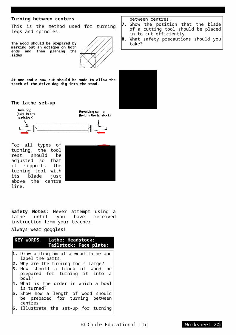
Turning between centersThis is the method used for turning legs and spindles.
The wood should be prepared by marking out an octagon on both ends and then planing the sides
At one end a saw cut should be made to allow the teeth of the drive dog dig into the wood.
The lathe set-up
For all types of turning, the tool rest should be adjusted so that it supports the turning tool with its blade just above the centre line.
Safety Notes: Never attempt using a lathe until you have received instruction from your teacher.
Always wear goggles!
KEY WORDS Lathe: Headstock: Tailstock: Face plate:
1. Draw a diagram of a wood lathe and label the parts.
2. Why are the turning tools large?3. How should a block of wood be prepared for
turning it into a bowl?4. What is the order in which a bowl is turned?5. Show how a length of wood should be
prepared for turning between centres.6. Illustrate the set-up for turning between
centres.7. Show the position that the blade of a cutting
tool should be placed in to cut efficiently.8. What safety precautions should you take?
Cable Educational Ltd Worksheet 20c

D&T Resistant Materials Making in Metal
SELECTING METALSThere are two classes of metals:
Ferrous - metals that contain iron and are affected by magnetism (apart from stainless steel).
Non-ferrous - metals that do not contain iron and are not affected by magnetism.
Metals can also be grouped into:
Pure metals - metals made up from only one chemical element e.g. copper or aluminium.
Alloys - metals made up from a mixture of elements, e.g. copper + zinc (brass) or lead + tin (solder)
AlloyingMetals are alloyed to improve the qualities of the individual pure metals e.g. both copper and tin as pure metals are both soft metals that are easily bent and scratched. When alloyed together ( 90% copper plus 10% tin) they produce bronze which is hard, rigid and resists scratching. Bronze is used for our ‘copper’ coins.
CorrosionWhen choosing metals, resistance to corrosion may be an important factor.
Corrosion is caused by oxygen in the air combining with the atoms of metal, at the surface of the metal, to create a new chemical called an oxide, e.g. iron oxide is called rust.In steel the rust layer is loose and can fall away; this exposes new atoms that will combine with oxygen to form new rust.
In non-ferrous metals the oxide layer is dense and does not fall away; this creates a barrier to the oxygen in the air and new corrosion occurs very slowly. The layer is called tarnish.
PropertiesBoth physical and mechanical properties vary greatly between different metals and alloys and are an important part of the selection process. (see worksheet 5a)
Available forms
Cable Educational Ltd Worksheet 24a

D&T Resistant Materials Making in Metal
FERROUS METALSNAME COMPOSITION PROPERTIES USES
Cast Iron Iron+ 3.5% carbon
Smooth skin with soft core,strong when compressed,self lubricating, cannot bebent or forged.
Vices, lathe beds,garden bench ends,car brake drums, etc
Mild SteelIron
+ 0.15 - 0.35%carbon
Ductile, malleable & tough,high tensile strength, poorresistance to corrosion,easily welded.
Car bodies, washingmachine bodies, nuts& bolts, screws, nails,girders, etc.
High Carbon Steel(tool steel)
Iron+ 0.8 - 1.5%
carbon
Very hard, rather brittle,difficult to cut, poor re-sistance to corrosion.
Tool bladese.g. saws, chisels,screwdrivers,punches, knives, files,etc.
High SpeedSteel
Iron+ tungstenchromiumvanadium
Very hard, heat resistant,remains hard when red
Drills, lathe cuttingtools, milling cutters,power hacksawblades etc.
StainlessSteel
Iron+ chromium
nickelmagnesium
Tough and hard, corrosionresistant, wears well, diffi-cult to cut, bend and file.
Cutlery, sinks, teapots,dishes, saucepans,etc.
NON-FERROUS METALS NAMENAME COMPOSITION PROPERTIES USES
Aluminium pure metal
Good strength/weight ratio,malleable and ductile, difficultto weld, non-toxic, resistscorrosion. Conducts heat andelectricity well. Polishes well.
Kitchen foil,saucepans,drinks cans,etc.
Duraluminaluminium
+ manganesemagnesium
Stronger than pure aluminium,nearly as strong as mild steelbut only one third the weight.
Greenhouses,window frames,aircraft bodies,etc.
Copper pure metal
Tough, ductile and malleable.Conducts heat and electricitywell. Corrosion resistant,solders well. Polishes well.
Electrical wire,central heating pipes,circuit boards,saucepan bases
Brass copper+ zinc
Quite hard, rigid, solderseasily. Good conductor of heatand electricity. Polishes well.
Water taps, lamps,boat fittings,Ornaments,door knockers.
Bronze copper+ tin
Tough, strong, wears verywell, good corrosionresistance.
Coins,wheel bearingsstatuesboat fittings
Tin pure metalWeak and soft, malleable andductile, excellent corrosionresistance, low melting point.
Solder (with lead)Coating over mildsteel (tin can)
Cable Educational Ltd Worksheet 24b

D&T Resistant Materials Making in Metal
Lead pure metalSoft, malleable, very heavy,corrosion resistant, lowmelting point, casts well,conducts electricity well.
Roof covering,Solder (with tin)Car battery plates
Zinc pure metal
Poor strength/weight ratio,weak, ductile and malleable,low melting point. Casts well.
Coating over mildsteel (galvanising)Die castings usedin carse.g. Carburettor
Cable Educational Ltd Worksheet 24c

D&T Resistant Materials Making in Metal
1. What is the difference between ferrous and non-ferrous metals?
2. What is an alloy and what advantages does it have over pure metal?
3. What is the difference between the corrosion of ferrous and non-ferrous metals?
4. What are the differences between mild steel and tool steel?
5. What is the main advantage of using stainless steel instead of mild steel?
6. Why is duralumin used in aircraft?
7. What property of copper makes it suitable for saucepan bases?
8. Why is copper used for water pipes but not the taps on the end of the pipes?
9. Which properties of bronze makes it suitable for making into coins?
10. Why do you not get everyday objects made from solid tin?
MARKING OUT METALPens and pencils do not work well on metal, they rub off easily and don’t show up well. Marking out is shown by scratched lines. To help the scratches to show up, before marking out, the surface of the metal can be covered with a thin layer of a quick drying ink called Engineer’s Blue. Marking out tools scratch away the blue layer to show the contrasting metal colour underneath.
Before marking out, the metal should be prepared by filing two datum edges, from which all measurements are made. These edges should be perfectly straight and be at 90° to each other.
Checking a square of metal using an engineer’s square. The ‘V’s are datum edge marks that point to the datum edges.
Scriber - used to scratch lines
Centre Punch - when hit with a hammer, it is used for making indents that position divider legs and drill points and stop them slipping.
Dividers - used for scratching circles and arcs.
Odd-leg CallipersUsed for scratching lines parallel to a datum edge
Combination SquareThe photo shows all three heads on the rule. In use, only one head at a time would be on the rule.
Cable Educational Ltd Worksheet 244
Centre square being used to find the centre of a disc. With the disc edges touching the arms, draw two lines at different angles, where they cross is the centre.
The angle head being used to draw a line at a set angle.
D&T Resistant Materials Making in Metal
1. Which tools are used to scratch lines on metal?
2. How can scratches on metal be made to show up more clearly?
3. How is the pivoting leg of a pair of dividers stopped from sliding over the surface of metal?
4. Which tool would you use for marking a line parallel to a long edge?
5. What is the ‘odd-leg’ for in a pair of odd-leg callipers?
6. Why is a scribing block adjustable?7. Why is a combination square called
‘combination’?8. Show how the centre square is used to find the
centre of the end of a length of round bar.9. Show how you can scratch a line at an angle of
25° to the edge of a bar of metal.10. Show how the ‘square’ head can be used to
scratch a line at right angles to the edge of a bar of metal.
SHAPING METAL – WASTING
SAWINGHacksaws are used for hand sawing metals. The frame is adjustable to take blades of different length.
Hacksaw BladesThe blades can be easily replaced when worn. Flexible, High Carbon Steel blades are used for general work on mild steel and non-ferrous metals. Rigid, High Speed Steel (HSS) blades are used for cutting hard steel.
Blades can be purchased with different size teeth:
Coarse - 14 or 18 TPI (teeth per inch) - thick metal.
Medium - 24 TPI- general work.
Fine - 32 TPI - thin metal.
If a coarse tooth blade is used on thin metal, the metal will catch between the teeth and the blade will jam.
For long cuts, the blade can be attached at right angles to the frame, so that the frame does not get
in the way.
For
cutting curves, the standard blade can be replaced by a Tension file, a round file held in the frame by special clips.
Thin metal can be cut easily by sandwiching it between two pieces of wood and then sawing through both the wood and the metal.
Thin wall tubing will collapse unless it is supported by placing a close fitting piece of dowel inside. Both the tube and the dowel are sawn.
To stop the saw blade from sliding over the metal when starting a cut, use a triangular file
Cable Educational Ltd Worksheet 245

D&T Resistant Materials Making in Metal
to file a groove on the waste side of the line. The saw teeth should fit into the groove.
1. Why is a hacksaw frame adjustable?
2. Specify the blade that you would use for cutting 50mm off a 200mm length of 3mm diameter mild steel.
3. Why should a 32TPI blade be used for cutting thin metal?
4. Show how you would set up the hacksaw to cut a long strip off a sheet of brass.
5. What would you use to cut a curved cut in a sheet of copper?
6. Illustrate how you would cut a thin sheet of aluminium without it bending.
7. How can you solve the problem of holding and sawing a length of thin walled brass tubing without it getting squashed?
8. How can you start to cut a piece of mild steel in exactly the right place?
FILING METALFiles are used for removing small amounts of metal and for smoothing a surface after it has been sawn. They are made from High Carbon Steel and come in many shapes, sizes and grades of cut.
The most common files are named after their cross-section.
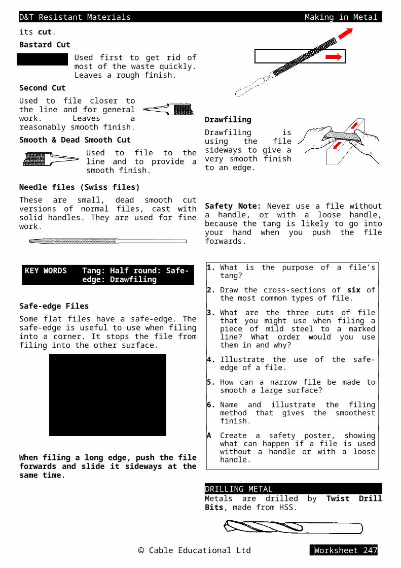
The roughness of a file is known by its cut.Bastard CutUsed first to get rid of most of the waste quickly. Leaves a rough finish.
Second CutUsed to file closer to the line and for general work. Leaves a reasonably smooth finish.
Smooth & Dead Smooth CutUsed to file to the line and to provide a smooth finish.
Needle files (Swiss files)These are small, dead smooth cut versions of normal files, cast with solid handles. They are used for fine work.
KEY WORDS Tang: Half round: Safe-edge: Drawfiling
Safe-edge FilesSome flat files have a safe-edge. The safe-edge is useful to use when filing into a corner. It stops the file from filing into the other surface.
When filing a long edge, push the file forwards and slide it sideways at the same time.
Cable Educational Ltd Worksheet 246

D&T Resistant Materials Making in Metal
DrawfilingDrawfiling is using the file sideways to give a very smooth finish to an edge.
Safety Note: Never use a file without a handle, or with a loose handle, because the tang is likely to go into your hand when you push the file forwards.
1. What is the purpose of a file’s tang?
2. Draw the cross-sections of six of the most common types of file.
3. What are the three cuts of file that you might use when filing a piece of mild steel to a marked line? What order would you use them in and why?
4. Illustrate the use of the safe-edge of a file.
5. How can a narrow file be made to smooth a large surface?
6. Name and illustrate the filing method that gives the smoothest finish.
A Create a safety poster, showing what can happen if a file is used without a handle or with a loose handle.
DRILLING METALMetals are drilled by Twist Drill Bits, made from HSS.
The smaller diameter bits have a straight shank and are held in a chuck. The larger diameter bits have a tapered shank and are held directly in the pillar drill spindle. The thin part at the end locks into the spindle and cannot slip under pressure, like a straight shank could in a chuck.
A ‘Jacobs’ Chuck
Note: For efficient cutting - Small diameter bits should turn at a fast speed. Large diameter bits should turn at a slow speed.
Pilot HolesFor holes in metal of 8mm diameter or larger, it is better to use a smaller drill bit first (4 or 5mm dia.). The smaller drill is less likely to wander off the centre punch mark. It also provides a hole that can guide (pilot) the larger drill.
A pilot hole guiding a larger drill bit
Cable Educational Ltd Worksheet 247

D&T Resistant Materials Making in Metal
Depth stopThe depth stop on a pillar drill is useful for drilling holes to a given depth and for drilling a number of holes that have to be the same depth. The adjusting nuts hit the stop and cannot move down any further.
Countersink BitThe bit is made from HSS. It is used to widen a previously drilled hole so that a countersunk screw head or rivet head can lie level with the surface.
Cone BitUsed for cutting and enlarging holes in thin sheet metal. This design does not catch in the metal and gives perfectly round holes.
Hand ViceA hand vice should be used to safely hold thin metal (up to 3mm thick), while it is being drilled.
KEY WORDS Shank: Chuck: Pilot hole: Depth stop: Hand Vice: Cone bit:
1. What is the purpose of a chuck on a pillar drill?
2. What is the advantage of the taper shank design for larger diameter drill bits?
3. Explain what a pilot hole is used for.
4. You need to drill three holes that are 6mm diameter and 10mm deep. How can you be sure that they will be identical?
5. A jobber bit will cut a near triangular hole in thin sheet metal, instead of a round hole. How
can you deal with this problem?
6. Illustrate a way of holding thin metal safely for drilling.
Cable Educational Ltd Worksheet 248

CHISELLINGChisels for metal are known as Cold Chisels and are made from High Carbon Steel.
The diagram below shows a cold chisel being used to chop out a rectangular shaped hole. The area for the hole has had small holes drilled all the way around the inside of the line (chain drilling). The chisel is hit with a hammer to cut between the holes until the inside is cut free. The edges are then filed with a safe-edge file.
A cold chisel can also be used to trim the edge of sheet metal. This leaves a new edge that needs minimal filing. The metal is placed in the vice so that the line to be cut to is level with the top of the vice jaws. The chisel is then rested on the top of the vice jaws and hit with a hammer.
KEY WORDS Cold chisel: Chain drilling: Tinsnips:
TINSNIPSTinsnips work like scissors and use a shearing action to cut thin sheet metal.
Straight SnipsUsed for cutting along straight lines.
Curved SnipsThe blades are curved to allow the snips to cut along curved lines.
Universal SnipsThe blades are designed to allow the snips to cut along both straight and curved lines.
When tinsnips are used the waste metal bends into a curved shape.
1. What are cold chisels made from?
2. Illustrate the term chain drilling.
3. How can a cold chisel help make a rectangular hole in a piece of sheet metal?
4. What is the advantage of using a cold chisel to trim the edge of a piece of sheet mild steel?
5. When would you choose to use a curved blade pair of tinsnips?
6. What is the disadvantage of using tinsnips to cut between two shapes that you want to keep?
7. What does the name ‘universal’ mean when applied to a pair of tinsnips?
Cable Educational Ltd Worksheet 26a

A. Research what is meant by shearing action and illustrate your findings.
LATHEWORK
A metalwork lathe is a machine used for a number of turning processes.
The cutting is done by a single point cutting tool. The tool is made from HSS or from tool steel with a hard wearing, tungsten carbide tip.
HSS tool Tungsten tipped tool
ProcessesA lathe is a very accurate piece of machinery and all turning processes can be carried out to an accuracy of one 100th of a millimetre.
Parallel turningThis reduces the diameter of a rod.
Facing offThis shortens the length of a rod and provides a smooth flat end at right angles to the side.
Cable Educational Ltd Worksheet 26b

Parting offThis is a way of cutting off a length of the rod. The diagram shows the parting process half finished.
KnurlingAdding a crossed pattern to the surface of a metal part to make it easier to grip. The lathe needs to run at a really slow speed to do this.
DrillingHoles drilled into the ends of rods are perfectly centred and run along the axis of the rod.
Note: The chuck revolves the work, while the drill bit is held still in the tailstock.
Centre drillThe centre drill is used for starting a hole. It provides a short pilot hole for the main drill bit.
KEY WORDS Facing off: Parting off: Boring: Centre drill:
1. Draw a labelled view of a metalworking lathe.
2. What materials are cutting tools made from?
3. How accurately can a lathe work?
4. Illustrate four turning processes.
5. How could you make a metal component easier to grip?
6. What are the differences between drilling using a pillar drill and drilling using a lathe?
7. How do you start the process of drilling a hole, when working with a lathe?
FORMING METAL – BEATINGBeating is probably the oldest method of shaping metals and relies upon metal’s malleability (being squashed and bent without splitting and cracking).
HOLLOWINGHollowing is a procedure used to produce shallow bowl shapes from circular sheet metal blanks.
1. A circular blank of metal (copper or brass etc.) is prepared by annealing it to make it more malleable.
AnnealingAnnealing is carried out by heating the metal to a dull red. The metal is now more malleable, so it will not split when it is hit with the mallet.
The surface will now be black (burnt tarnish) and this needs to be cleaned off before hollowing. Either emery cloth can be used to clean it, or the still warm disc can be placed into a bath of dilute sulphuric acid.
Note: If the metal is aluminium, it cannot be heated to red heat because it never glows red. Soap should be rubbed onto the surface, and the metal heated gently until the soap turns a dark brown, the correct temperature has now been reached for annealing. The burnt soap can be washed off with
water.
To form the hollow shape, either a hollowed hardwood block, or a leather sandbag can be used.
Forming block Sandbag
Cable Educational Ltd Worksheet 26c
2. The metal disc is placed at a shallow angle as shown and is hit with an egg shaped Bossing Mallet.
3. After each blow the disc should be rotated one space, so the next blow lands beside the first. Starting from the outer edge, spiral into the centre. The bowl shape will form automatically.
SINKINGSinking is a procedure that can produce a shallow bowl with a lip around the top edge and a flat base.
The metal disc, shown in the diagram in transparent form, is placed against both dowel pegs. The edge on the top surface of the sinking block remains horizontal and produces the lip.
A blocking hammer is then used to create the hollow shape.
PLANISHINGPlanishing is a procedure that is carried out after hollowing or sinking, it is used:
a) to remove any unwanted bumps and to correct the overall shape.b) to harden the metal and make it more rigid.
A cut away view of a Planishing Hammer being used. The bowl is placed over a Mushroom Stake. Starting in the centre, the bowl is revolved one space after each blow. The blows should spiral outwards to the edge.
The surface becomes covered in little indents that can be left to give a textured finish, or removed, by smoothing the surface with an abrasive stone.
KEY WORDS Hollowing: Bossing Mallet: Sinking: Planishing:
1. Describe how metal should be prepared for hollowing.
2. What tools can be used to form a bowl shape?
3. Illustrate the hollowing procedure.
4. What is the difference between hollowing and sinking?
5. Sketch a product made by hollowing and a product made by sinking.
6. Why should a hollowed product be planished?
7. Give an illustrated description of the planishing process.
FORMING METAL – BENDINGThin sheet metal (up to 1.5mm thick) can be bent, by hand, into boxes, trays and cylinders. The metal sheet needs to be prepared as a ‘net’ or ‘development’ before bending.
Note: It is a good idea to make a full size card model first, so that costly metal is not wasted if there is an error.
A typical net for a metal box
To bend an edge to 90° on a sheet of metal that is larger than the jaws of the vice, folding bars can be used to hold the sheet.
Hit with mallet andwooden striker
To enable both sides and ends of a box or tray to be folded, a wooden block can be cut to be the same size as the base.
Note: The wood has to be thicker than the height of the
Cable Educational Ltd Worksheet 26d
To make the edges more rigid and to make them less sharp, they can be folded to make a ‘safe edge’.

sides.
One edge bent to 90°
If the side is hit directly with a mallet it tends to end up with a wavy edge. It is better to hold a hardwood striker at a slight angle against the side and hit the striker with the mallet.
Forming a CylinderFor bending curves, a machine that has three adjustable rollers is used. The tightness of the curve can be controlled by altering the position of each roller.
KEY WORDS Net: Folding Bars: Forming Machine:
1. What thickness of sheet metal can be bent by hand?
2. Draw a net of a tray made from sheet brass. The tray is to be 200mm long, 150mm wide, with 20mm high sides, when finished.
3. Why should a card model of the ‘net’ be made?
4. How can the edges of the tray be made safer?
5. What advantages are there in using folding bars for bending the edge of a sheet of metal,
instead of vice jaws?
6. How can both the sides and ends of a box or tray be folded up?
7. How can you avoid the edge of the sides becoming wavy?
8. Illustrate how a cylinder could be made from a sheet of copper.
A Make a paper or card model of a net that would be suitable for making a copper container for a house plant in a 100mm diameter flowerpot, that is 95mm tall.
FORGINGHand forging is one of the oldest methods of shaping metal and is associated with the work of a blacksmith. Today there are many computer controlled processes.
One reason for forging metal is to improve its strength. When it is hit it is squashed and becomes more dense. Also, a shaped product will have the ‘grain’ (layers of crystals) flow around the shape.
A machine cut shape with A forged shape withsharp internal corners curved (filleted) corners
Straight grain lines that Grain lines are closer can be the source of a together and follow the
crack at the internal corner corner shape, giving extra strength.
The heated metal is shaped on an anvil by hitting it with a heavy hammer.
Holding the metalTongs are used to hold the metal being forged, they come in large variety of styles and sizes, to hold
Cable Educational Ltd Worksheet 26e
1. Hold the bar at a slight angle to the anvil face and hit on one side, the anvil face flattens the other side at the same time.
2. Turn the bar 90° and hit again to make the point square in shape.
3. Hit each corner of the square shape to turn it into an octagonal shape
4. Continue turning the bar and hitting the corners until the point is round in shape.

different shapes of metal bar.
Open-mouth tongsFor gripping thick flat material
Pickup tongsFor gripping awkward shapes including round bars.
Note: It is important that the correct tongs are used to grip the hot metal firmly.
BendingBending a bar on the anvil, using the rounded edge of the face.
Drawing DownTo make a round bar pointed it has to be drawn down. Drawing down requires four stages to avoid the tip splitting.
Cable Educational Ltd Worksheet 26f

UpsettingUpsetting is the term given to the process of thickening the metal. This is useful for maintaining strength when drilling a hole.
TwistingHeat the bar to a bright red and then grip it in the vice and slide on a special twisting tool, or use a large tap wrench. Twist the metal while it is still red hot. Twisting will only occur between the vice and the wrench.
Forging a LoopA loop is useful for the end of a handle to improve grip and to allow the object to be hung up.
1. Bend the length of the loop circumference over the rounded edge of the anvil. Circumference of loop
2. Start the curve by hammering it over the anvil beak.
3. Work towards the end of the metal to complete the curving.
4. Close the loop by tapping it with a hammer on top of the anvil face.
ScrollingCreating scrolls from strips of wrought iron has been a traditional form of decoration for gates and screens. Today, the scrolls are made of mild steel and are still popular.
An ‘S’ scroll
To make identical scrolls a master scroll is used. The metal is heated to bright red in a forge and then tightly wrapped around the master scroll. To stop the metal from slipping the end is prepared by forging the end into a hook shape.
Forging a hook shape to stop the metal from sliding around the master scroll.
Forming the scroll by wrapping the hot metal around the master scroll.
Plan view of master scroll hook
front view of master scroll (shown without the piece of metal being formed)
KEY WORDS Anvil: Tongs: Drawing Down: Upsetting: Scrolling:
1. Explain how forging a component can make it stronger than sawing and filing it to shape.
2. Draw a blacksmith’s anvil and label its parts.
3. Why is it very important that the correct size tongs are used when forging?
4. Show how the anvil can be used to bend the end of a bar of mild steel.
5. Illustrate how a point can be forged on a piece of round bar so that it does not split.
6. Explain the process of upsetting and why it is done.
7. When twisting a bar, how can you make sure that the twisting is exactly where you want it?
Cable Educational Ltd Worksheet 27a

8. Illustrate the stages used for forging a loop.
9. Give an example of what is meant by a metal scroll.
10. How do you prepare a bar for scrolling on a master scroll?
CASTING IN METALCasting is a method of shaping metal into simple or complicated shapes without producing any waste. Removed metal can be re-melted and used again.
Sand CastingThe oldest form of casting involves pouring molten metal into a shaped hole made in damp sand and letting it cool. This is the form of casting that can be done in school using low melting point metals, such as the aluminium alloy (LM4).
Stages in Sand Casting1. Making the Pattern The pattern is the shape to be cast, made in wood. It is this that is used to make the correct shape of hole in the sand. The pattern should be tapered so that it can be taken out of the sand without dislodging any sand grains. The taper is known as the Draft.
Pattern without draft being removed. It dislodges grains of sand into the mould as it rubs the sides.
Pattern with draft being removed without touching the sides. The mould remains clear.
Internal corners need to have a fillet to stop cracks appearing during cooling.
A fillet - plastic or plasterA crack in a non filleted corner rounded filling
A pattern that because of its shape would dislodge sand when it was removed needs to be split into two or more sections.
Pattern split in half with locating dowels and holes to keep the halves in line.
2. Moulding Moulding is the process of creating the hollow shape in sand.
The diagram shows the moulding box. It is in two halves; the top is called the cope and the bottom the drag. Neither has a base. They are located together by a pin and hole system at each end. On the inside of the sides is a recess to help hold the sand in place.
A) The drag is turned upside down and put on the base board. The pattern is placed in the middle. Moulding sand, made damp with oil or water, is sieved over the pattern until the pattern is covered.
B) The rest of the sand is shovelled in and then rammed with a rammer until it is packed tightly. The surface is then levelled by scraping a metal strip across (strickling).
C) The drag is turned the right way up and the cope is then placed on top. The top half of the pattern is added and also the sprue pins are positioned. Sand is then added and rammed to fill the cope.
A sprue pin is a cone shape, made from wood that is used to create holes in the sand that will allow the molten metal to be poured into the mould and the excess
Cable Educational Ltd Worksheet 27b
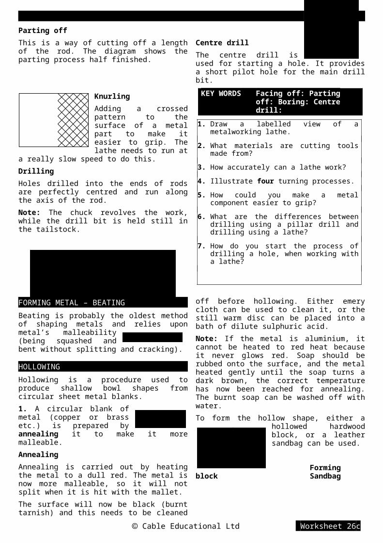
metal to rise to the top. The holes are called sprues.
Cable Educational Ltd Worksheet 27c
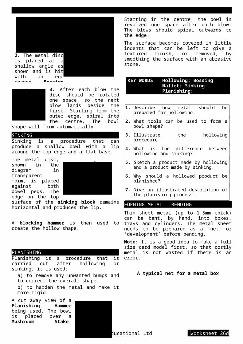
D) The cope is now lifted off and the top half of the pattern and the sprue pins are removed.
Channels called gates are cut between the sprue pin holes and the pattern to allow the molten metal to flow into the mould cavity.
E) A wood screw is screwed into the pattern and it is tapped from side to side to release the pattern from the sides of the sand mould. The pattern is then carefully lifted vertically from the mould.
F) The cope is placed back on the drag. A hollow basin shape (pouring basin) is cut into the sprue hole that the metal will flow into (runner). A thin metal rod is pushed into the sand to create narrow holes that will allow air to escape when the metal is poured.
3. Pouring The mould is now ready for pouring. This must be carried out by a teacher. Molten metal is slowly poured into the pouring basin, the basin will overflow into the runner. The metal will then flow into the mould. Trapped air can escape up the riser or through the sand above the pattern into the vent holes. The metal should be poured until it fills the riser.
When the metal is cooled and solidified the mould can be broken open. The casting will come free with its gates and sprues attached, these will have to be removed by sawing them off and filing down the stumps. The sprues can be remelted.
CoresIf the handle needs a hole through it so that it can swivel or slide on a bar, it can be cast with the hole in place. To have a hole in a casting a core needs to be used.
For a split pattern, the core needs to split as well. The core is a cylindrical shape made from sand mixed with a binder and baked in the core box. This makes it rigid so it will not break under its own weight.
The pattern needs to be altered to include extensions called core prints. These leave a depression in the sand to hold the core in place.
The core is placed in the core prints in the mould cavity. The molten metal will flow around the core.
When the casting has cooled, the core is rammed out of it with a steel rod. This leaves a hole through the centre.
KEY WORDS Pattern: Mould: Draft: Fillet: Sprue: Gate:
1. Explain why ‘draft’ is required on the sides of a pattern.
2. What is a ‘fillet’ in casting and why should it be used?
3. Why are some patterns split and how are the two halves held in place?
4. Why is the moulding box made in two halves?
5. Explain the mould making process using notes and diagrams.
6. What is the purpose of the vents in a mould?
7. What has to be done to the casting after its removal from the mould before it can be used?
8. What is a core used for when casting?
9. How does the pattern have to be altered if a
Cable Educational Ltd Worksheet 28a

core Is required?
10. How is a core held in place in the mould cavity?
METAL FABRICATION – MECHANICAL
Machine ScrewsMachine screws have a parallel thread and need a threaded hole to screw into. They come in a wide variety of materials and sizes and are used for semi-permanent joining.
Instead of drawing a complicated thread each time, a simple schematic drawing can be used.
Schematic drawing of a thread cheese head
countersunk head pan head
Common machine screws
Clearance holes in top material
Threaded holes in base material
socket head Grub screw (no head)
Clearance hole for thescrew to slide through.
Self-tapping screw Pilot hole for the screw to bite into.
The self-tapping screw is used on thin sheet metal. It cuts its own thread into the pilot hole. This can
speed up the manufacturing process, cheaply.
Cable Educational Ltd Worksheet 28b

Nut and boltA strong method of holding two parts together
Washers are used to spread the load over a slightly larger area and to prevent damage to the material as the nut is tightened.
Some washers are used to prevent vibration from loosening the nut.
Spring washer Serrated washers
RivetsRivets are a quick and easy method of permanently joining materials. However, they can be drilled out if the materials need to be separated later.
Rivets are made from iron, aluminium and brass and come in many lengths and diameters.
round headflat head
Pop rivets are used when it impossible to get to both sides of the joint.
Pop rivets holding a sheet of metal to square tubing.
METAL FABRICATION – THREADINGWhen the size of the thread has been decided the
hole has to be drilled to the correct tapping size. This is a hole that is smaller in
diameter than the thread diameter (nominal size), so that the thread can be cut into its side. There are printed tables to tell you which size drill bit to use.
Metal can be held together by screws screwed into threaded holes, and also threaded rod can be screwed into a threaded hole. Cutting an internal thread into the side of a hole is known as Tapping the hole, because the tools used to cut the thread are called Taps. Cutting an external thread on the outside of a length of rod is known as Threading and the tool used to cut the thread is known as a Die.Before a hole can be threaded, the size of the thread must be decided. In school, threads from 2mm diameter to 12mm diameter in 1mm jumps can be cut. A tap and die have the size stamped on them, e.g. M8 x 1.25. The ‘M’ stands for Metric. The 1.25 is the distance in millimetres, between the tip of each thread tooth, this is called the Pitch.Taps are normally sold in sets of three. If a blind hole (a hole that does not go all the way through a piece of material) is to be tapped all three taps are used in turn, starting with the taper tap. The taper allows the tap to start with its tip firmly in the hole and the thread to be cut gradually deeper into the side, with each turn.
tap wrench
The diagram shows a plug tap, held in a tap wrench, completing the threading of a blind hole.
Tap wrench viewed from above
Cable Educational Ltd Worksheet 28c

An external thread on a metal rod is cut by using a die held in a die stock. The die is adjustable so that threads that are slightly smaller or larger than the nominal size can be cut. This allows for a loose or tight fit between the external and internal threads. Adjustable
split die
It is a good idea to cut the thread with the die split open as far as possible and then test the fitting of the external and internal threads. If the threads are too tight then close the die a little, re-cut and test
again. Repeat the process until the thread runs smoothly.
Make sure that the die stock is at right angles to the rod to stop a ‘drunken’ thread being cut.
True thread Effect of drunken thread
KEY WORDS Tap: Die: Blind hole: Tap wrench: Tapping size: Die stock: Drunken thread:
1. What does the term ‘tapping a hole’ mean?
2. Where would you find M10x1.5 printed and what does each part stand for?
3. How can you measure the ‘pitch’ of a thread?
4. What is a ‘tapping size’ hole?
5. Illustrate a ‘blind’ hole.
6. What are the three taps that make up a set? How can you tell
the difference between them?
7. Make a neat sketch of a Tap Wrench.
8. What is used to cut an external thread?
9. Explain the use of the three screws found on the Die Stock.
10. With the help of diagrams explain the effect of a drunken thread. How can this be avoided?
METAL FABRICATION – RIVETING
The tools required for riveting with solid rivets are:
Rivet Set & SnapThe hole in this tool is used to set up the joint by making sure that the pieces of metal and the head of the rivet are pressed firmly together. The hollow is used to form the shank of the rivet into a second ‘head’.
The peen Ball-peen HammerBall-peen hammerThe peen (also spelt ‘pein’) is used to roughly form the second head of the rivet.
Stage 1Place the rivet in the joint and mark a line 1½ times the diameter of the shank from the metal to be
joined. Remove the rivet and cut the shank to the line.
Stage 2Use two ‘Set & Snaps’. Hold the lower one in the vice and tap the upper one with the normal face of the hammer. Make sure that there are no gaps in the
joint.
Stage 3
Cable Educational Ltd Worksheet 28d

Hammer the rivet shank into a rough mushroom shape using the Ball Peen part of the hammer head.
KEY WORDS Set: Snap: Ball Peen: Pop rivet
Stage 4Use the snap part of the upper snap & set to smooth and shape the second head by hitting it with the hammer. The rivet is now complete.
Countersink RivetingStage 1 and 2 are the same as for a round head rivet, except the head of the countersunk rivet should be placed on a solid flat surface. The shank is hammered by the peen until it fills the countersunk hole.
The rough mushroom shape is then filed until the head is flat and flush with the surface of the metal sheet.
Lining up rivet holesWhen more than one rivet is used it is important that all the holes in one metal sheet line up with the holes in the sheet to be joined to it.
To make sure the holes line up, mark out and drill one pair of holes only. Rivet them together and then line up the metal sheets. The remaining holes can then be marked out and drilled.
Pop Riveting
Steel pin Rivet body
The pin is pulled by jaws in the gun. The pin head squeezes into the tube of the rivet. The pin then breaks away and leaves the head behind.
1. Illustrate how the ball peen of a hammer may be used, when riveting.
2. What is the purpose of the Rivet Set & Snap?3. How can you make sure that all the holes line
up when using more than one rivet to make a joint?
4. How is the second head formed on a pop rivet?
SOFT SOLDERINGSoft soldering is a permanent method of joining most metals such as steel, tinplate, copper and
Cable Educational Ltd Worksheet 28e

brass.
Note: Aluminium cannot be soft soldered.
Solder is an alloy of Lead and Tin. The amounts of lead and tin vary, depending on the melting point and flow rate that is required e.g.
Purpose Alloy MeltingPoint Hardness
Electrical work More tinthan lead 183oC
Soft andslightlyflexible
Plumbing(e.g. Joining
copper pipes)
More leadthan tin
Up to250oC
Hardandrigid
Electrical solderingSoft solder in wire form is used with an electric soldering iron to solder components to an electric wire or to a Printed Circuit Board (PCB)
1. Check that the parts to be joined together and the soldering iron tip are clean. (use emery cloth to clean them)2. Hold the parts to be joined together in place.3. Attach a heat sink (a device placed between the joint and the component that will soak up the heat and stop the component from getting too hot) e.g. a crocodile clip.4. Check that the soldering iron is hot enough by melting a little solder onto the tip.5. Hold the hot tip of the soldering iron against the joint for approximately 3 seconds, to preheat the joint.6. Touch both the joint and the tip of the soldering iron with the solder wire, then remove it and the soldering iron the moment the end of the wire melts. (approximately 1 second).7. Wait until the surface of the joint sets and goes dull before you remove the heat sink.
Sheet metal solderingTo make a strong joint between sheets of metal a
Flux must be applied before soldering.
FluxA flux is a chemical that does two essential jobs to help create a strong joint.1. When the metal is heated up for soldering it stops an oxide layer forming (tarnish). Molten solder must be able to soak into the surfaces of the metal sheets being joined, to make a strong joint.2. It breaks down the surface tension of the molten solder to allow it to flow in between the metal sheets.There are two types of flux for soft soldering:Acid - a clear liquid that when applied will clean the surface of the sheet metal by dissolving any oxide layer or grease, before soldering starts. This flux must be washed away with water as soon as the joint has been soldered, otherwise it will weaken the joint.Passive - a brown resin that looks like grease. This does not dissolve any old oxide layers, so surfaces need to be cleaned with emery cloth first. It does not need to be washed away at the end.
1. Apply flux to both 2. Melt solder onto the surfaces hot tip (tinning the iron)
4. Place the parts together and rub the hot iron over the joint to re-melt the solder. Then let it cool and set.
KEY WORDS Heat sink: PCB: Flux:
1. Which metals is soft solder made from?
2. What is the melting point range of soft solder?
3. Why must the parts being soldered be clean?
4. Why do you need to use a heat sink when soldering electrical components and how does it work?
5. Why do you need to wait until the surface of the joint goes dull before moving it?
6. What are the two main reasons for using a flux?
7. Explain the difference between the two types of flux.
8. Illustrate the stages of soldering two sheets of metal together.
A. Create an illustrated instruction sheet for soft
Cable Educational Ltd Worksheet 28f
3. Apply solder to both fluxed surfaces

soldering a resistor onto a PCB.
HARD SOLDERINGHard soldering is a similar technique to soft soldering except that far higher temperatures are used and far stronger joints are made.
BrazingThe ‘solder’, called spelter, is brass, (copper and zinc). It melts at 870°C.
The heat is supplied by a gas blowtorch attached to a brazing hearth, or by an oxyacetylene torch (see welding).
Brazing is normally used for joining steel together.
Brazing HearthJoints need to be held together with wire or interlocked because the flame is powerful and can move loose sections of steel.
Brazing FluxFor brazing, the flux is a powder made from the salt Borax. It needs to be mixed with water to form a paste so that it is not blown away by the flame.
The flux, in paste form, should be spread over the joint.
Short lengths of spelter can be cut and laid along the joint at intervals, on top of the flux.
Place the joint on the brazing hearth surrounded by fire bricks. The bricks are important because they reflect the heat and flame so that the joint can get to a
high enough temperature to melt the spelter.
Silver solderingSilver solder is an alloy of copper, zinc and silver. The melting point is lower than spelter and ranges from 625°C to 800°C. The lowest melting point solder has the most silver added. Silver solder is used for joining brass, copper, nickel and pure silver. There are three grades of silver solder:
Easy flow - melts between 625°C and 690°CMedium - melts between 690°C and 725°CHard - melts between 725°C and 800°C
The grade system is useful when a number of joints are close together and cannot be soldered in one go.
If one type of solder only was used, then the solder put on the seam would re-melt and the joint would spring open when the base was being heated for joining. When the three grades are used, as shown in the diagram, each joint melts at a lower temperature than the last, so earlier joints stay set.
Flux used for silver soldering is also called Easy-Flow. It works at a lower temperature than brazing flux
The diagram shows a typical set-up for silver soldering a seam. Small pieces of solder are laid at regular intervals on the fluxed joint.
Wires to stop the cylinder fromopening up when heated
KEY WORDS Spelter: Brazing: Easy flow:
1. What is ‘spelter’ and what is it used for?
2. Why do joints need to be held in place for hard soldering?
3. Why do the wires used for holding joints together have a loop put in them?
4. What type of flux is used when brazing and in what form is it applied?
5. Make an annotated sketch of the set-up of a joint ready for brazing on the brazing hearth.
Cable Educational Ltd Worksheet 28g
Tankard(made from nickel-silver)

6. What are the constituents of silver solder?
7. What are the three grades of silver solder and what are their melting point ranges?
8. Illustrate how the three grades of silver solder are used and explain why they are necessary.
WELDING METALWelding is a permanent method of joining two pieces of the same metal together by melting them both and letting them fuse together as they cool down and become solid again.
Welding is normally used for steel and aluminium. There are three main types of welding:
Gas - using an oxyacetylene gas flameArc - using an electric spark
Resistance - using an electric current.
Gas WeldingThis is the most common form of welding used in schools. Heat is supplied by an oxyacetylene torch that burns acetylene gas mixed with pure oxygen, to a temperature of 3,500°C.Cross section Pool of molten metal Completed weld
(showing evidence of circular flame movement)
The filler rod is used to build up the joint and to replace the metal that has evaporated. The flame is moved forward in a series of small circular movements to heat a wider area than the diameter of the flame.
Flux is not normally used for welding steel, but is essential in large quantities, when welding aluminium.
Before welding along a joint, both ends need a small weld to hold the ends together. This is called a tack weld.
If the ends are not tacked the pieces will warp in the heat and the joint will separate.
Cable Educational Ltd Worksheet 28h

Arc WeldingThe joint metal and the filler rod are both connected to an electric circuit. When the rod is held a short distance away from the joint, sparks fly between the two. The temperature of the sparks is so high that both the end of the rod and the joint metal melt and form a weld pool.
Resistance WeldingAlso known as ‘spot welding’, this is suitable for thin sheet steel. It relies upon passing a current through the sheets of metal and heating them up where they touch each other, because this is where there is most resistance. (Electrical resistance produces heat).
Two electrodes squeeze the sheets together and then pass an electric current through for approximately 2 seconds, then hold until the weld sets (2 or 3 seconds).
Resistance welding does not produce a continuous weld. The result is like a line of tack welds 30 to 40 mm apart.
KEY WORDS Oxyacetylene: Tack welding: Arc: Resistance:
1. What are the three main types of welding?2. Which gases are burnt to produce a welding
flame and at what temperature do they burn at?
3. Why is filler rod used?4. The flame is moved in a series of small circles,
why is this?5. Illustrate why a joint should be tack welded at
both ends first.6. Explain, with illustration, how arc welding
works.7. What provides the heat when spot welding?8. Illustrate the spot welding cycle and the
resulting joint.
HEAT TREATMENTWork HardeningWhen metal is bent or shaped by hitting with a mallet, the area being reshaped becomes harder and more brittle. This is why it is possible to break a length of steel wire by repeatedly bending it backwards and forwards. Each time it is bent it becomes harder and more brittle until it breaks off.
One problem is that new metal products are likely to have areas that have been shaped and are too brittle. It is possible to get rid of the brittle areas by annealing the metal.
AnnealingAnnealing is the process of heating metal to soften it and remove the brittleness.
METAL METHOD COOLING TIME
Aluminium
Put soap on thesurface and heat with ablowtorch until the soapturns black (400oC)
Can be cooled bywashing off the soapin cold water.
Steel Heat to cherry red(725oC)
Cool slowly buried insand.
Copper Heat to dull red (500oC) Cool naturally in stillair.
Annealing steel
Hardening and TemperingHigh Carbon Steel is the only common metal that
Cable Educational Ltd Worksheet 28i

can be hardened by heat treatment.
It is hardened by heating to bright red and then cooling it quickly by plunging it into room temperature water. It is now very hard, but unfortunately also very brittle, too brittle to use without it breaking. It needs to be softened a little to reduce the brittleness, this is done by the process of tempering.
Tempering1. Clean the area to be 2. Heat gently until the correct tempered. colour appears and moves to the
tip. (see table)
3. Plunge the tip into water and swirl it around. It is now the correct hardness and not too brittle.
COLOUR TEMPERATURE USES
Light brown 240oC(still brittle, not tough)
Drills, milling cutters
Dark brown270oC
(quite tough)Scissors, knives
Dark purple290oC
(tough, not brittle) Screwdrivers, spanners
Case HardeningMild steel cannot be hardened and tempered because it does not contain enough carbon for the process to work. However, if mild steel is heated to bright red heat and then buried in carbon rich powder, the carbon melts and soaks into the surface of the steel to a depth of up to 2mm.
The mild steel can now be hardened and tempered in the same way as high carbon steel. This is known as Case Hardening, because only the surface with the extra carbon becomes hard, the inner core of mild steel remains soft.Hard outer case Case hardened mild steel is very tough, because any cracks that start in the hard, brittle outer case are stopped by the soft core.
Soft inner core
KEY WORDS Annealing: Tempering: Case hardening:
1. Explain how repeat bending of mild steel wire will result in it breaking in two.
2. What is meant by the term ‘annealing’?
3. How would you anneal aluminium?
4. How would you anneal mild steel?
5. How can high carbon steel be hardened by heat?
6. Why does hardened steel need to be tempered?
7. Illustrate the stages of tempering a screwdriver head. (state the colour that you need to heat the blade to).
8. How is mild steel treated so that it can be hardened?
9. Case hardened mild steel is tough. Why?
10. Between the temperatures of 230°C and 300°C, steel can be said to have a built-in thermometer. How can this be true?
METAL FINISHESFinishes on metal are used to both protect and decorate the surface. If left unprotected most metals tarnish and eventually corrode.
PreparationIt is important that the surfaces are cleaned up by removing any dirt, grease and tarnish. The most common method is to use Emery cloth (blue or black coloured grit stuck to a cloth backing). The cloth can be wrapped around a file and then rubbed over the surface, up and down in one direction, to give a clean looking finish.
PolishingFurther prepare the surface by using a finer grade or worn piece of emery cloth to get a smooth matt finish. Polishing can then be done by hand using liquid metal polish and a cloth, or on a Buffing machine, by holding the surface against a revolving mop, lightly coated with an abrasive wax.
Safety noteAlways use the underside of the buffing wheel so that the product being polished is thrown away from you if it is pulled out of your
Cable Educational Ltd Worksheet 28j
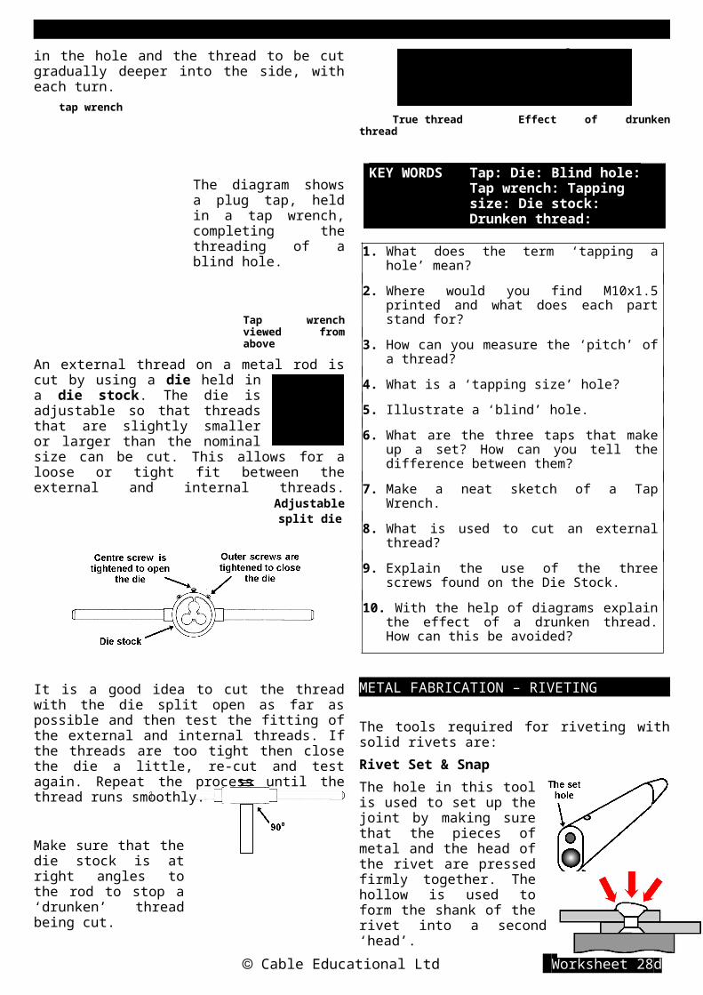
hand. Never hold the product with a rag, it can catch in the wheel and drag your hand into the machine.
PaintingThe surface should be thoroughly degreased using white spirit. A special primer coat for metal can then be applied. Although normal gloss paint can be used over the primer, an enamel gloss is best, as it is less likely to flake off. The toughest paint finish is Hammerite. This paint does not require a primer coat, except on aluminium, and can be painted over rust.
Lacquering Lacquering metal is similar to varnishing wood. A thin layer of cellulose gum is brushed on the cleaned surface, giving a clear protective coat that will allow the colour of the metal to show through.
Dip Coating A plastic coating is a tough and waterproof finish that comes in a range of colours.
The product to be coated is heated in an oven, or by a blow torch, to a temperature between 200°C and 400°C. It is then plunged into a fluidised bath of polyethylene powder for a few seconds. When it is removed the product should be rotated slowly as the plastic cools and sets, so that no drips occur.
Fluidising is blowing cold air through the powder so that the powder bubbles like boiling water.
Blown air
EnamellingEnamelling is using powdered coloured glass, which is melted, flows over the surface and then bonds to it. It is normally used as a decorative finish on copper for items of jewellery.
On steel, Vitreous enamel is a coating that is used for the casing of washing machines and refrigerators etc.
AnodisingAnodising is used on aluminium and is a method of producing a dense, clear oxide layer that resists corrosion. The layer can be dyed with coloured inks.
ElectroplatingElectroplating is using a process called electrolysis to coat one metal with a thin layer of another metal. For example, covering brass with chromium for bath taps and nickel with silver (silver plate) for an ornament.
KEY WORDS Buffing: Enamel: Lacquer: Fluidising: Anodising: Electroplating:
1. Explain the best way of cleaning metal so that it is ready to receive a finish.
2. In what way can a buffing machine be a dangerous machine to use?
3. Why is enamel paint better than standard gloss on metal.
4. What sort of finish would you give brass so that the shiny yellow surface can still be seen?
5. Explain, with diagrams, how the handle of a junior hacksaw can be plastic coated.
6. What method could you use to decorate a pair of copper earrings?
Cable Educational Ltd Worksheet 28k

D&T Resistant Materials Making in Plastics
SELECTING PLASTICSThere are two main classes of plastic.
Thermoplastics - can be reshaped by heating. They will try and return to their original shape if re-heated.
Thermosetting Plastics - cannot be reshaped by heating and can withstand higher temperatures than thermoplastics.
All modern plastics are made mainly from oil, coal and extracts from plants. They are synthetic (not natural - man-made) and come in hundreds of types, each with their own set of properties. Many have been made to order by materials scientists, e.g. The drinks industry wanted a lightweight plastic that would not crack when dropped or when under pressure, to make bottles for fizzy drinks. Scientists produced Polyethylene teraphthalate (PET). (Can you pronounce this?) Most property changes are made by adding additives to the basic plastic.
The following are common additives:
Plasticisers - make the plastic less brittle.
Pigments - colour the plastic
Fillers - powdered additives, e.g. mica reduces electrical conductivity, asbestos allows higher temperature use, etc.
Stabilisers - protect plastic from ultra violet light that can make it become brittle.
Flame retardants - make the plastic less likely to catch fire.
ThermoplasticsPLASTIC PROPERTIES USES
US
ED
IN S
CH
OO
L
Polymethyl-methacrylate(Acrylic or
PMMA)
Rigid, hard, can beclear, very durableoutside, polishes toa high shine.
Illuminatedsigns,windows,baths,
Polyvinylchloride
(PVC)
Rigid, quite hard,good chemicalresistance, tough.
Pipes,guttering,window,frames,
Polyethylene(polythene)
Flexible, soft, goodchemicalresistance,feels waxy
Food bags,buckets,bowls,bottles.
Polyamide(nylon)
Tough,self lubricating,resists wear, goodchemicalresistance
Gearwheels,bearingstights,combs
Polystyrene Lightweight, hard,rigid, can be clear,good waterresistance
Model kits,utensils,containers,packaging
ExpandedPolystyrene
Very lightweight,floats, good heatinsulator
Insulation,packaging
PLASTIC PROPERTIES USES
US
ED
IN IN
DU
STR
Y
Polyethyleneteraphthalate
(PET)
Tough, clear,lightweight,
Fizzydrinksbottles
Polypropylene Lightweight,flexible, resistscracking andtearing
Climbingropes,crisppackets
Acrylonitrilebutadiene
styrene(ABS)
Very tough,scratch resistant,good chemicalresistance
Casings forcameras,kettles,vacuumcleaners
Thermosetting plasticsPLASTIC PROPERTIES USES
US
ED
IN S
CH
OO
L Polyester resin(mixed with glassfibre - GRP)
Hard, rigid, brittle,tough when mixedwith glass or carbonfibres
Boatand carbodies,paperweights
Epoxy resin(Araldite)
Strong, goodchemical and heatresistance, sticks toother materials well
Adhesiveencapsulatingelectroniccomponents
US
ED
IN IN
DU
STR
Y Polyethyleneteraphthalate
(PET)
Rigid, hard scratchresistant, water andstain resistant
Table ware,laminatetop coating
Ureaformaldehyde
Rigid, hard, strong,heat resistant,does not bendwhen heated,good electricalinsulator
Electricalplugs andsockets,doorknobs
1. What are the two classes of plastic and what is the difference between them?
2. Why are there many types of plastic?
3. Give an example of how a materials chemist can change the properties of a plastic.
4. Why would you add a stabiliser to a plastic?
5. Which plastic would you choose for making a window frame and why?
6. Which plastic would you choose to protect a china ornament sent by post?
7. Which plastic would you use for making a house number sign and why?
8. Why is nylon a good plastic for making combs?
9. Which plastic would be best for making the casing of a cool-wall toaster?
10. Which plastic has the properties required for making a saucepan handle?
Cable Educational Ltd Worksheet 33

D&T Resistant Materials Making in Plastics
KEY WORDS Thermoplastic: Thermoset: Synthetic:
MARKING OUT PLASTICPlastic in schools is normally in sheet or rod form. The sheet plastic is often protected on both sides by a layer of paper or clear polyethylene. These layers protect against accidental scratching and therefore need to be kept on as long as possible.
Marking out needs to be done on the protective layer if possible. Normal pencils can be used on the paper layer. The polyethylene layer will need a chinagraph pencil or a spirit based pen such as an overhead projector (OHP) pen. (use a non-permanent pen)
Marking out a line on the protecting paper layer over a sheet of Acrylic
Marking out a curve using a pencil compass.
If the protective layer has been removed then masking tape can be used to cover the area to be marked out.
Curve drawn on masking tape pieces
Using a marking gauge to scratch a line along the masking tape. The scratched line can be made clear with a pencil afterwards.
Using a non-
permanent spirit marker to draw directly upon the plastic, around a template
Remember:Always mark out in the corner of a sheet of plastic to reduce the amount of waste and to make it easier to cut out.
Note:If the plastic is to be cut out on a scroll saw or band saw, the masking tape will also help in keeping the temperature of the plastic below its melting point, so that the cut does not weld itself back together again.
To find the centre of the end of a length of plastic rod use a centre square. The rod should be touching both arms, then a line drawn along the inside edge of the ruler should pass through the centre of the rod. To find where along the line the centre is, turn the rod through 90° and draw a second line, where the two lines cross is the true centre.
1. Why are sheets of plastic often covered with a layer of paper?
2. What markers can be used on the surface of Acrylic?
3. How can the point of a compass be stopped from sliding over the smooth surface of a sheet of plastic?
4. Give two good reasons for using masking tape
Cable Educational Ltd Worksheet 34
Centre square

D&T Resistant Materials Making in Plastics
on unprotected sheet plastic.
5. Illustrate the reasons why shapes should be marked out in the corner of a sheet of plastic and not in the middle.
SHAPING PLASTICS – WASTINGSawingThere are two main problems that occur when sawing plastics.
1. Hard, rigid plastics such as Acrylic and Polystyrene can crack easily if they are not well supported.
2. Power saws tend to create so much friction heat that the cut plastic softens and welds itself back together again behind the blade.
A keyhole support block The block is held in a vice.
When using a scroll saw or bandsaw the heat problem can be solved by sticking ‘sellotape’ over the line to be cut, or draw the line on masking tape that was put on for marking out. The tape takes away enough heat from the plastic to stop it welding together behind the blade.
Clear tape stuck over the line to be sawn
Planing and FilingA woodwork plane can be used on the edges of most plastics, provided the blade is
set to make a very fine cut. Hard plastics like Acrylic will blunt the blade very quickly It is best to have a plane set aside for use on plastics only. It is very important to support the plastic when it is in the vice to stop it cracking when pressure is put on it by the plane.
For support, when planing or filing, sandwich the plastic sheet between two wooden blocks with the plastic only just showing above the wood. This is then held in a vice.
When filing the edge of a sheet of plastic, never file at right angles to the edge, because the plastic may crack. Always file at an angle or drawfile.
DrillingNormal jobber drills that can be used for wood and metal are not suitable for plastic unless they are reground to a different angle. A standard drill will catch the plastic as it breaks through the bottom of the hole and cause cracking around the hole.
Any hole over 6mm diameter is best drilled using the pilot hole method. First drill the hole with a 4mm drill and then redrill with a 6mm drill and continue using drills that are 2 or 3mm larger in diameter until the correct size is reached.
1. What problems do you need to overcome when sawing plastic?
2. Why do you think the keyhole support block works so well?
3. When using a support block, why do the teeth of the blade need to be pointing towards the block?
4. Why should you stick tape over a saw line when cutting plastic with a power saw?
5. Illustrate how you would support a sheet of plastic for planing or filing.
Cable Educational Ltd Worksheet 35

D&T Resistant Materials Making in Plastics
6. Show how you should file the edge of a sheet of plastic to avoid cracks occurring.
7. Why is it not a good idea to use a jobber drill from the store to drill a hole in plastic?
8. Explain how you would plan to drill a 10mm diameter hole in a sheet of plastic.
Cable Educational Ltd Worksheet 36

D&T Resistant Materials Making in Plastics
SHAPING PLASTICS – FORMING
BendingThermoplastics in sheet form can be heated gently to between 160°C and 180°C and then bent into shape. If the sheet is held in position while it cools it will remain in its new shape while it is at room temperature or below. If the plastic sheet is re-heated then it will try to return to its original shape of a flat sheet. This property is known as plastic memory.
To bend a straight line use a strip heater. A heating element will heat the plastic only along the area held above it. When the plastic in the heated area becomes soft it can be removed and held over a former, or in a jig, to hold it in shape until it cools.
Relief PatternsPlastic memory can be used to create patterns that stick out from the surface of the sheet. Acrylic has the best memory effect for this process.
1. Place a shape made from steel wire or brazing rod on a sheet of MDF.
2. Place a plastic sheet, heated in an oven until it is soft, between the shape and a second sheet of MDF. The sandwich is then pressed together so the shape makes an indent in the plastic. Leave to cool. Acrylic
Remove to lower level
3. Remove the top surface by filing, milling or rubbing over an emery board. Some of the indent must be left. Remove to lower level indent
4. Re-heat in the oven until the indented plastic returns to its memorised height. The surrounding plastic has been partly removed and therefore cannot return to its original height.
Press FormingPress forming is also known as Plug and Yoke forming. This process is useful for making three dimensional hollow shapes such as a shallow tray. A two part mould is used to shape a heated sheet of plastic.
The mould can be made from plywood or MDF. The shape that is the plug is smaller than the hole in the yoke. The difference is the same as the thickness of the plastic to be formed, all the way round.
The soft sheet of hot plastic is sandwiched between the plug and yoke. G-clamps are used to force the plug and yoke together.
When the plastic has cooled to room temperature it can be removed and will be the required tray shape.
Cable Educational Ltd Worksheet 37

D&T Resistant Materials Answers
Vacuum FormingMost thermoplastics are suitable for vacuum forming. This process is useful for making shaped packaging trays, such as those that hold a layer of chocolates in a box. Other items made by this process are face masks, the shelving on the inside of refrigerator doors and plastic baths.
The mould can be made from MDF and is attached to a baseboard made from drilled hardboard or thin plywood.
The sides should be tapered (draft), to make it easier for the plastic and mould to separate at the end.
Draft
Vacuum forming machine
The table with the mould is raised into the plastic and the vacuum pump is switched on. The plastic sheet is then sucked tightly over the mould. The mould can be removed from the plastic moulding when the plastic has cooled.
Air sucked out by vacuum pump
The waste can be trimmed from the base of the moulding by using a profile router. This machine uses a spinning abrasive disc, that can be set at different heights, to cut away the waste flange.
Blow MouldingBlow moulding is a process that can produce hemispherical shapes (half a sphere).
The blow moulding clamp can be made from plywood or MDF.
The heated, soft plastic sheet is blown up like a balloon. The air used to blow the hemisphere also cools the plastic so it quickly becomes rigid.
KEY WORDS Plastic memory: Plug & Yoke: Vacuum forming: draft flange
1. Explain the term ‘plastic memory’.2. Illustrate how a straight line, 90° bend, can be
made in a 3mm thick sheet of PVC.3. How can a relief pattern be made in a square
of acrylic? Use annotated diagrams.4. A small tray is required to hold salt & pepper
shakers. How would you make the tray in rigid polystyrene?
5. Why are vacuum forming moulds made with drafted edges?
6. Illustrate the vacuum forming process.7. How can the flange be cut away from a
moulding?8. What are the three ways in which a
hemispherical shape can be produced from a plastic sheet?
9. Explain, with diagrams, how compressed air can be used to create a half balloon shape in sheet plastic.
Cable Educational Ltd

D&T Resistant Materials Answers
Cable Educational Ltd