Embed Size (px)
Citation preview
DWS-1008 User’s Manual
D-Link Systems, Inc. I
Table of Contents
Table of ContentsProduct ContentsSystem RequirementsIntroductionHardware OverviewFeaturesInstallation Overview Getting StartedInstallation
ConfigurationCLI Quickstart Command Accessing the CLIConfiguration Overview Configuring for Authenticating Users Configuring APs for Wireless UsersConfiguring a Service Profile
Configuring AAA For Administrative and Local AccessOverview of AAA AccessTypes of Administrative AccessFirst-Time Configuration via the ConsoleCustomizing AAA with Globs and Groups
Configuring and Managing Ports and VLANsSetting the Port TypeDisplaying Port StatisticsConfiguring and Managing VLANsManaging the Layer 2 Forwarding DatabaseConfiguring the Aging Timeout PeriodPort and VLAN Configuration Scenario
Configuring and Managing IP Interfaces and ServicesMTU SupportConfiguring and Managing IP InterfacesConfiguring and Managing IP RoutesManaging the Management ServicesManaging SSHManaging TelnetConfiguring and Managing DNSConfiguring and Managing AliasesConfiguring and Managing Time ParametersConfiguring and Managing NTPManaging the ARP Table
11234578
11121718282937
5253545456
63636973788181
8686869093949799
101102105107
DWS-1008 User’s Manual
D-Link Systems, Inc. II
Logging In to a Remote DeviceTracing a RouteIP Interfaces and Services Configuration Scenario
Configuring SNMPEnabling SNMP VersionsSetting SNMP SecurityConfiguring a Notification ProfileConfiguring a Notification TargetEnabling the SNMP ServiceDisplaying SNMP Information
Configuring DWL-8220AP Access PointsOverviewService ProfilesRadio ProfilesConfiguring Access PointsSpecifying the Country of OperationConfiguring AP Port ParametersConfiguring SecurityConfiguring a Service ProfileConfiguring Radio-Specific ParametersAssigning a Radio Profile and Enabling RadiosDisabling or Reenabling RadiosDisplaying AP Configuration Information
Configuring User EncryptionConfiguring WPAConfiguring RSNConfiguring WEPEncryption Configuration Scenarios
Configuring RF Auto-TuningRF AutoTuning OverviewChanging RF AutoTuning SettingsDisplaying RF AutoTuning Settings
Wi-Fi MultimediaHow WMM Works in MSSDisabling or Reenabling WMMDisplaying WMM Information
Configuring and Managing Spanning Tree ProtocolEnabling the Spanning Tree ProtocolChanging Standard Spanning Tree ParametersConfiguring and Managing STP Fast Convergence FeaturesDisplaying Spanning Tree InformationSpanning Tree Configuration Scenario
109110111
115116120121125127128
130130139143146146152156159166168168170
176178185188190
197197203205
208208209209
211211211216219223
DWS-1008 User’s Manual
D-Link Systems, Inc. III
Configuring and Managing IGMP SnoopingDisabling or Reenabling IGMP SnoopingDisabling or Reenabling Proxy ReportingEnabling the Pseudo-QuerierChanging IGMP TimersEnabling Router SolicitationConfiguring Static Multicast PortsDisplaying Multicast Information
Configuring and Managing Security ACLsAbout Security Access Control ListsCreating and Committing a Security ACLMapping Security ACLsModifying a Security ACLUsing ACLs to Change CoSEnabling Prioritization for Legacy Voice over IPSecurity ACL Configuration Scenario
Managing Keys and CertificatesWhy Use Keys and Certificates?About Keys and CertificatesCreating Keys and CertificatesDisplaying Certificate and Key InformationKey and Certificate Configuration Scenarios
Configuring AAA for Network UsersAbout AAA for Network UsersAAA Tools for Network UsersConfiguring 802.1X AuthenticationConfiguring Authentication and Authorization by MAC AddressConfiguring Last-Resort AccessConfiguring AAA for Users of Third-Party APsAssigning Authorization AttributesOverriding or Adding Attributes Locally with a Location PolicyConfiguring Accounting for Wireless Network UsersDisplaying the AAA ConfigurationAvoiding AAA Problems in Configuration OrderConfiguring a Mobility ProfileNetwork User Configuration Scenarios
Configuring Communication with RADIUSRADIUS OverviewBefore You BeginConfiguring RADIUS ServersConfiguring RADIUS Server GroupsRADIUS and Server Group Configuration Scenario
225225225225226227228228
232232234242245249251253
255255256259263264
270270275280285289290294303306309310312313
320320320320323326
DWS-1008 User’s Manual
D-Link Systems, Inc. IV
Managing 802.1XManaging 802.1X on Wired Authentication PortsManaging 802.1X Encryption KeysManaging 802.1X Client ReauthenticationManaging Other TimersDisplaying 802.1X Information
Managing SessionsAbout the Session ManagerDisplaying and Clearing Administrative SessionsDisplaying and Clearing Network Sessions
Rogue Detection and CountermeasuresAbout Rogues and RF DetectionSummary of Rogue Detection FeaturesConfiguring Rogue Detection ListsEnabling CountermeasuresDisabling or Reenabling Active ScanEnabling AP SignaturesDisabling or Reenabling Logging of RoguesEnabling Rogue and Countermeasures NotificationsIDS and DoS AlertsDisplaying RF Detection Information
Managing System FilesAbout System FilesWorking with FilesManaging Configuration FilesBacking Up and Restoring the System
Appendix A - TroubleshootingFixing Common Setup ProblemsRecovering the System PasswordConfiguring and Managing the System LogRunning TracesUsing Show CommandsRemotely Monitoring TrafficCapturing System Information for Technical Support
Appendix B - Supported RADIUS AttribitesSupported Standard and Extended Attributes
Appendix C - DHCP ServerHow the MSS DHCP Server WorksConfiguring the DHCP ServerDisplaying DHCP Server Information
Appendix D - GlossaryAppendix E - Technical SpecificationsAppendix F - WarrantyAppendix G - Registration
328328329332334335
338338338340
345345348350355355356356356356362
366366368372376
378378380380387391392399
400400
405406406407409441444449
�
DWS-1008 User’s Manual
D-Link Systems, Inc.
Product Contents
Product Contents
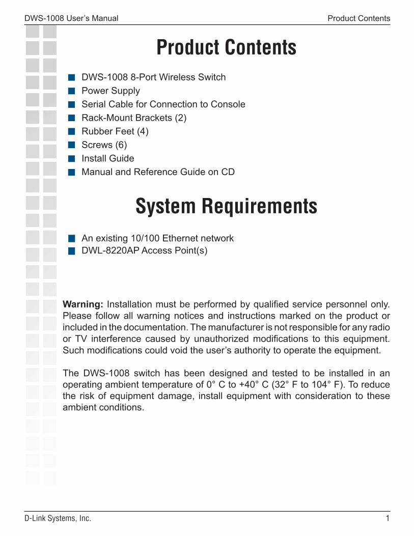
DWS-1008 8-Port Wireless SwitchPower SupplySerial Cable for Connection to ConsoleRack-Mount Brackets (2)Rubber Feet (4)Screws (6)Install GuideManual and Reference Guide on CD
System RequirementsAn existing 10/100 Ethernet networkDWL-8220AP Access Point(s)
Warning: Installation must be performed by qualified service personnel only. Please follow all warning notices and instructions marked on the product or included in the documentation. The manufacturer is not responsible for any radio or TV interference caused by unauthorized modifications to this equipment. Such modifications could void the user’s authority to operate the equipment.
The DWS-1008 switch has been designed and tested to be installed in an operating ambient temperature of 0° C to +40° C (32° F to 104° F). To reduce the risk of equipment damage, install equipment with consideration to these ambient conditions.
�
DWS-1008 User’s Manual
D-Link Systems, Inc.
IntroductionThe D-Link® AirPremier® MobileLAN™ DWS-1008 is a wireless LAN switch optimized for deployment in the Small-Medium Enterprise (SME) environment. The DWS-1008 is designed to allow easy user installation and operation yet support advanced wireless switch features such as secure mobility, policy enforcement, and AAA and 802.1x offload capabilities.
The D-Link MobileLAN solution is powered by Trapeze Networks and executes Trapeze Networks’ Mobility System Software (MSS), which maintains the intelligence of the MobileLAN system. In addition to managing users’ identities as they roam, the DWS-1008 configures and controls all aspects of the complementing DWL-8220AP Wireless Switch Dualband Access Points.
AAA Authentication Offloading CapabilityThe MobileLAN DWS-1008 supports Administration, Authorization, and Authentication (AAA) policies to ensure maximum security. Rather than checking the identity of a connecting user from the switch’s local database, user authentication policies can be sent back to an AAA server for complete verification. This offloading capability ensures that the WLAN will not overload when clients are simultaneously connecting to the network.
User-Based Authentication ServicesThis wireless switch delivers Identity-based Networking, which provides user-based services such as virtual private group membership, personal firewall filters, time-of-day/day-of-week access, encryption type, authentication, usage tracking, location tracking, and associated network statistics.
Easy DeploymentThe DWS-1008 includes eight 10/100 Mbps ports with integrated PoE to enable network connectivity to any connected DWL-8220AP. It is designed for distributed deployments in the wiring closet or small or medium offices. It can support up to six directly connected DWL-8220APs and up to six more DWL-8220APs connected indirectly.
Maximum Performance With Load Balancing CapabilitiesThe DWS-1008 performs Layer 2 forwarding and also comes with extensive Layer 3-4 and identity-tracking capabilities. It integrates seamlessly with wired infrastructures and offers redundant load-sharing links, 802.1q trunking, spanning tree and per-VLAN spanning tree (PVST+). It also supports IGMP snooping, which is vital to supporting IP multicast streams.
Introduction
�
DWS-1008 User’s Manual
D-Link Systems, Inc.
Hardware Overview
Hardware Overview (Front Panel)
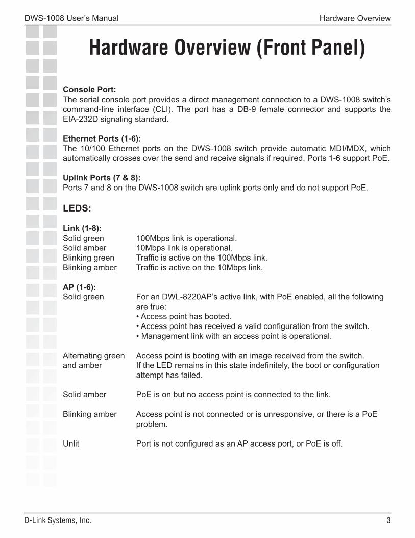
Console Port:The serial console port provides a direct management connection to a DWS-1008 switch’s command-line interface (CLI). The port has a DB-9 female connector and supports the EIA-232D signaling standard.
Ethernet Ports (1-6):The 10/100 Ethernet ports on the DWS-1008 switch provide automatic MDI/MDX, which automatically crosses over the send and receive signals if required. Ports 1-6 support PoE.
Uplink Ports (7 & 8):Ports 7 and 8 on the DWS-1008 switch are uplink ports only and do not support PoE.
LEDS:
Link (1-8):Solid green 100Mbps link is operational.Solid amber 10Mbps link is operational.Blinking green Traffic is active on the 100Mbps link.Blinking amber Traffic is active on the 10Mbps link.
AP (1-6):Solid green For an DWL-8220AP’s active link, with PoE enabled, all the following are true: • Access point has booted. • Access point has received a valid configuration from the switch. • Management link with an access point is operational.
Alternating green Access point is booting with an image received from the switch.and amber If the LED remains in this state indefinitely, the boot or configuration attempt has failed.
Solid amber PoE is on but no access point is connected to the link.
Blinking amber Access point is not connected or is unresponsive, or there is a PoE problem.
Unlit Port is not configured as an AP access port, or PoE is off.
�
DWS-1008 User’s Manual
D-Link Systems, Inc.
Features
Power Features
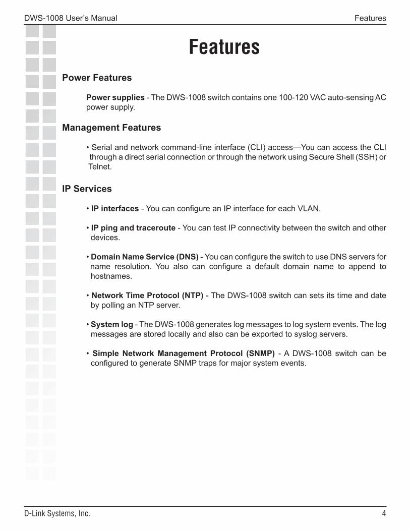
Power supplies - The DWS-1008 switch contains one 100-120 VAC auto-sensing AC power supply.
Management Features
• Serial and network command-line interface (CLI) access—You can access the CLI through a direct serial connection or through the network using Secure Shell (SSH) or Telnet.
IP Services
• IP interfaces - You can configure an IP interface for each VLAN.
• IP ping and traceroute - You can test IP connectivity between the switch and other devices.
• Domain Name Service (DNS) - You can configure the switch to use DNS servers for name resolution. You also can configure a default domain name to append to hostnames.
• Network Time Protocol (NTP) - The DWS-1008 switch can sets its time and date by polling an NTP server.
• System log - The DWS-1008 generates log messages to log system events. The log messages are stored locally and also can be exported to syslog servers.
• Simple Network Management Protocol (SNMP) - A DWS-1008 switch can be configured to generate SNMP traps for major system events.
Features
�
DWS-1008 User’s Manual
D-Link Systems, Inc.
Installation Overview
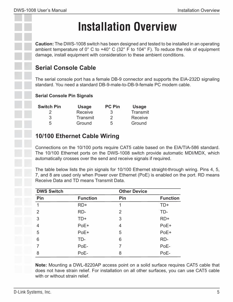
Installation OverviewCaution: The DWS-1008 switch has been designed and tested to be installed in an operating ambient temperature of 0° C to +40° C (32° F to 104° F). To reduce the risk of equipment damage, install equipment with consideration to these ambient conditions.
Serial Console Cable
The serial console port has a female DB-9 connector and supports the EIA-232D signaling standard. You need a standard DB-9-male-to-DB-9-female PC modem cable.
Serial Console Pin Signals
Switch Pin Usage PC Pin Usage 2 Receive 3 Transmit 3 Transmit 2 Receive 5 Ground 5 Ground
10/100 Ethernet Cable Wiring
Connections on the 10/100 ports require CAT5 cable based on the EIA/TIA-586 standard. The 10/100 Ethernet ports on the DWS-1008 switch provide automatic MDI/MDX, which automatically crosses over the send and receive signals if required.
The table below lists the pin signals for 10/100 Ethernet straight-through wiring. Pins 4, 5, 7, and 8 are used only when Power over Ethernet (PoE) is enabled on the port. RD means Receive Data and TD means Transmit Data.
DWS Switch Other DevicePin Function Pin Function1 RD+ 1 TD+2 RD- 2 TD-3 TD+ 3 RD+4 PoE+ 4 PoE+5 PoE+ 5 PoE+6 TD- 6 RD-7 PoE- 7 PoE-8 PoE- 8 PoE-
Note: Mounting a DWL-8220AP access point on a solid surface requires CAT5 cable that does not have strain relief. For installation on all other surfaces, you can use CAT5 cable with or without strain relief.
�
DWS-1008 User’s Manual
D-Link Systems, Inc.
Installation Hardware and Tools
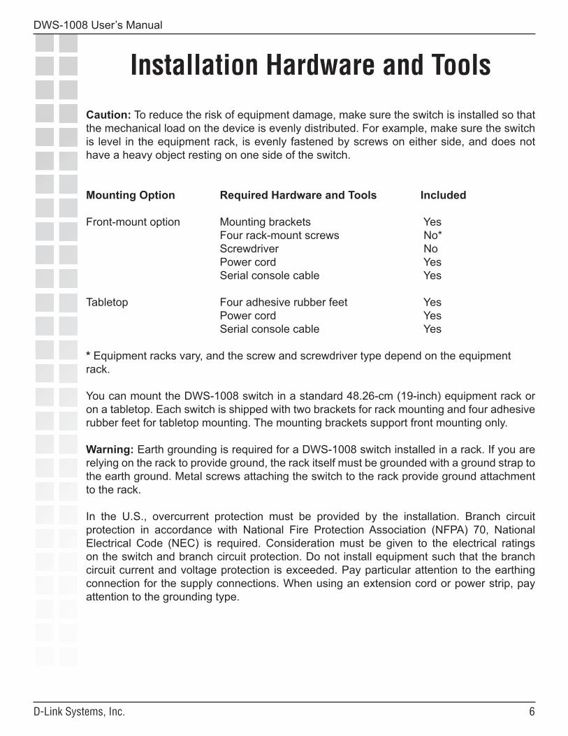
Caution: To reduce the risk of equipment damage, make sure the switch is installed so that the mechanical load on the device is evenly distributed. For example, make sure the switch is level in the equipment rack, is evenly fastened by screws on either side, and does not have a heavy object resting on one side of the switch.
Mounting Option Required Hardware and Tools Included
Front-mount option Mounting brackets Yes Four rack-mount screws No* Screwdriver No Power cord Yes Serial console cable Yes
Tabletop Four adhesive rubber feet Yes Power cord Yes Serial console cable Yes
* Equipment racks vary, and the screw and screwdriver type depend on the equipmentrack.
You can mount the DWS-1008 switch in a standard 48.26-cm (19-inch) equipment rack or on a tabletop. Each switch is shipped with two brackets for rack mounting and four adhesive rubber feet for tabletop mounting. The mounting brackets support front mounting only.
Warning: Earth grounding is required for a DWS-1008 switch installed in a rack. If you are relying on the rack to provide ground, the rack itself must be grounded with a ground strap to the earth ground. Metal screws attaching the switch to the rack provide ground attachment to the rack.
In the U.S., overcurrent protection must be provided by the installation. Branch circuit protection in accordance with National Fire Protection Association (NFPA) 70, National Electrical Code (NEC) is required. Consideration must be given to the electrical ratings on the switch and branch circuit protection. Do not install equipment such that the branch circuit current and voltage protection is exceeded. Pay particular attention to the earthing connection for the supply connections. When using an extension cord or power strip, pay attention to the grounding type.
�
DWS-1008 User’s Manual
D-Link Systems, Inc.
Please read the following before you begin:
Mobility System Software* (MSS) operates a D-Link Mobility System wireless LAN (WLAN) consisting of DWS-1008 switches, and DWL-8220AP access points (AP). MSS has a command-line interface (CLI) on the switch that you can use to configure and manage the switch and its attached access points.
You configure the DWS-1008 switch and DWL-8220AP access points primarily with set, clear, and show commands. Use set commands to change parameters. Use clear commands to reset parameters to their defaults. In many cases, you can overwrite a parameter with another set command. Use show commands to display the current configuration and monitor the status of network operations.
* The Mobility System Software is built-in to the firmware on the DWS-1008 switch. No additional software is required.
The switch supports two connection modes:
• Administrative access mode, which enables the network administrator to connect to the switch and configure the network.
• Network access mode, which enables network users to connect through the switch to access the network.
The D-Link Mobility System consists of the following components:
• DWS-1008 switch - Distributed, intelligent machines for managing user connectivity, connecting and powering DWL-8220AP access points, and connecting the WLAN to the wired network backbone.
• DWL-8220AP access points - Wireless access points (APs) that transmit and receive radio frequency (RF) signals to and from wireless users and connect them to a DWS-1008 switch.
• Mobility System Software™ (MSS™) - The operating system (firmware) that runs all D-Link DWS-1008 switches and DWL-8220AP access points in a WLAN, and is accessible through a command-line interface (CLI).
Getting Started
Getting Started
�
DWS-1008 User’s Manual
D-Link Systems, Inc.
Installation
Installation
Equipment Rack Installation
1. Remove the four bracket screws from each side of the switch.
2. Align a bracket over the screw holes: • For a front-mount equipment rack, align the bracket so that the bracket flange is flush with the switch’s front panel and extends away from the switch. • For a center-mount equipment rack, align the bracket so that the bracket flange is located near the center screw holes.
3. Reinsert the screws to secure the brackets to the switch.
4. Repeat for the other bracket.
5. Lift the switch into position in the equipment rack.
6. Insert the bottom rack-mount screws into the bracket flanges to secure the switch to the equipment rack, then insert the top screws.
Warning: To prevent the switch from slipping, do not release the switch until all the rack-mount screws are tight.
Tabletop Installation
1. On a clean work surface with no debris, carefully turn the switch upside down.
2. Wipe the four placement locations for the rubber feet to clear away any oil or dust. The location areas are marked by X’s.
3. Attach the four rubber adhesive feet over the X’s.
4. Turn the switch right-side up, and place the switch in position on the table.
Powering On a DWS-1008 Switch
Warning: The switch relies on the building’s installation for overcurrent protection. Ensure that a fuse or circuit breaker no larger than 120 VAC, 15 A U.S. (240 VAC, 10 A international) is used on the phase conductors.
1. Make sure any insertable power supply is fully seated in the switch.
2. Attach a power cord to an AC power source.
3 Plug the power cord into the power supply. The switch will begin booting as soon as you plug in the power cord(s).
�
DWS-1008 User’s Manual
D-Link Systems, Inc.
Installation (continued)
Installation
Powering On a DWS-1008 Switch (continued)4. Observe the power supply LED for each connected power supply to verify that the LED is steadily glowing green. This indicates normal power supply operation.
Connecting to a Serial Management Console
Initial configuration of the DWS-1008 switch requires a connection to the switch’s CLI through the serial console port.
To connect a PC to the serial console port:
1. Insert the serial cable into the PC port.
2. Insert the other end of the cable into the serial console port on the switch.
3. Start a standard VT100 terminal emulation application on the PC, and configure the following modem settings:
• 9600 bps • 8 bits • 1 stop • No parity • Hardware flow control off or disabled
4. Open a connection on a serial port. If the switch is already powered on, press Enter three times to display a command prompt. Refer to the “Accessing the CLI” for more information.
Troubleshooting Serial Management
Connection1. Verify that the switch is powered on.
2. Verify that the serial cable is fully inserted in the PC and switch’s console ports.
3. Verify that the correct modem settings are configured in the terminal emulation application as shown in step 3 above.
4. Verify that you opened the connection on the PC port connected to the switch. For example, if you inserted the cable in PC port COM1, make sure you open the connection on COM1 instead of COM2 or another port. If none of the previous steps results in a management connection, use another serial cable.
�0
DWS-1008 User’s Manual
D-Link Systems, Inc.
Connecting to the Network
Use the following procedures to connect a DWS-1008 switch to DWL-8220AP access points or other 10/100 Ethernet devices.
Connecting to a DWL-8220AP or Other 10/100 Ethernet Devices
Note: The 10/100 Ethernet ports are configured as wired network ports by default. You must change the port type for locally connected DWL-8220AP access points, and for wired end stations that use AAA through the DWS-1008 switch to access the network.
For installations in Japan: Provide an earthing connection before you connect the mains plug to the mains. When disconnecting the earthing connection, make sure to disconnect only after you pull out the mains plug for the mains.
1. Insert a CAT5 cable with a standard RJ-45 connector. The 10/100 Ethernet ports on the DWS-1008 switch provide automatic MDI/MDX.
2. If the cable is directly attached to a DWL-8220AP access point: • For a first-time installation, set the port type to activate the link. • If the port type is already set for an access point, observe the appearance of the AP LED for the port.
3. If the cable is attached to a wired end station that uses AAA through the switch to access the network:
• For a first-time installation, set the port type to activate the link. • If the port type is already set for a wired authentication port, go on to step 4.
4. If the cable is directly attached to a device other than an DWL-8220AP access point: • Observe the appearance of the Link LED for the port. • If the Link LED is unlit, check the cable and verify that the device at the other end of the link is operating.
Installation (continued)
Installation
��
DWS-1008 User’s Manual
D-Link Systems, Inc.
Configuration
Configuration
You can use CLI (Command Line Interface) to configure a new switch or to continue configuration of a partially configured switch:
CLI (Command Line Interface)
You can configure a switch using the CLI by attaching a PC to the switch’s Console port. After you configure the switch for SSH or Telnet access, you also can use these protocols to access the CLI.
��
DWS-1008 User’s Manual
D-Link Systems, Inc.
Configuration (continued)
Configuration
CLI Quickstart Command
The quickstart command runs a script that interactively helps you configure the following items:
• System name • Country code (regulatory domain) • System IP address • Default route • Administrative users and passwords • Unencrypted (clear) SSID names • Encrypted (crypto) SSID names and dynamic WEP encryption for encrypted SSIDs’ wireless traffic • Usernames and passwords for secure access using 802.1X authentication using PEAP-MSCHAP-V2 and secure wireless data encryption using dynamic Wired Equivalent Privacy (WEP) • Directly connected DWL-8220AP access points • Distributed access points
The quickstart command displays a prompt for each of these items, and lists the default if applicable. You can advance to the next item, and accept the default if applicable, by pressing Enter. Depending on your input, the command also automatically generates the following key pairs and self-signed certificates:
• SSH key pair (always generated) • Admin key pair and self-signed certificate (always generated) • EAP (802.1X) key pair and self-signed certificate (generated if you type usernames and passwords for users of encrypted SSIDs)
The command automatically places all ports that are not used for directly connected access points into the default VLAN (VLAN 1).
Caution: The quickstart command is for configuration of a new switch only. After prompting you for verification, the command erases the switch’s configuration before continuing. If you run this command on a switch that already has a configuration, the configuration will be erased. In addition, error messages such as Critical AP Notice for directly connected MPs can appear.
��
DWS-1008 User’s Manual
D-Link Systems, Inc.
Configuration (continued)
Configuration
To run the quickstart command:
1. Attach a PC to the DWS-1008 switch’s serial console port. Use the following modem settings: 9600 bps, 8 bits, 1 stop, no parity, hardware flow control disabled.
2. Press Enter three times, to display a username prompt (Username:), a password prompt (Password:), and then a command prompt such as the following:
DWS-1008-aabbcc>
Each switch has a unique system name that contains the model number and the last half of the switch’s MAC address.
3. Access the enabled level (the configuration level) of the CLI:
DWS-1008-aabbcc> enable
4. Press Enter at the Enter password prompt.
5. Type quickstart. The command asks you a series of questions. You can type ? for more help. To quit, press Ctrl+C.
One of the questions the script asks is the country code. For a list of valid country codes, refer to the section “Appendix: Country of Operation”.
Another question the script asks is, “Do you wish to configure wireless?” If you answer y, the script goes on to ask you for SSID and user information, for unencrypted and encrypted SSIDs. If you answer n, the script generates key pairs for SSH and the administrative users you entered, generates a self-signed administrative certificate, and then ends.
Quickstart Example
This example configures the following parameters: • System name: DWS-1008-Corp • Country code (regulatory domain): US • System IP address: 10.10.10.4, on IP interface 10.10.10.4 255.255.255.0
Note: The quickstart script asks for an IP address and subnet mask for the system IP address, and converts the input into an IP interface with a subnet mask, and a system IP address that uses that interface. Likewise, if you configure this information manually instead of using thequickstart command, you must configure the interface and system IP address separately.
• Default route: 10.10.10.1
��
DWS-1008 User’s Manual
D-Link Systems, Inc.
Configuration (continued)
Configuration
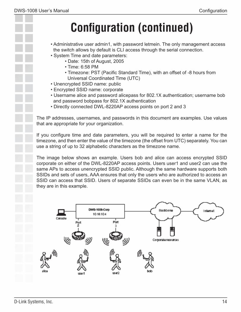
• Administrative user admin1, with password letmein. The only management access the switch allows by default is CLI access through the serial connection. • System Time and date parameters: • Date: 15th of August, 2005 • Time: 6:58 PM • Timezone: PST (Pacific Standard Time), with an offset of -8 hours from Universal Coordinated Time (UTC) • Unencrypted SSID name: public • Encrypted SSID name: corporate • Username alice and password alicepass for 802.1X authentication; username bob and password bobpass for 802.1X authentication • Directly connected DWL-8220AP access points on port 2 and 3
The IP addresses, usernames, and passwords in this document are examples. Use values that are appropriate for your organization.
If you configure time and date parameters, you will be required to enter a name for the timezone, and then enter the value of the timezone (the offset from UTC) separately. You can use a string of up to 32 alphabetic characters as the timezone name.
The image below shows an example. Users bob and alice can access encrypted SSID corporate on either of the DWL-8220AP access points. Users user1 and user2 can use the same APs to access unencrypted SSID public. Although the same hardware supports both SSIDs and sets of users, AAA ensures that only the users who are authorized to access an SSID can access that SSID. Users of separate SSIDs can even be in the same VLAN, as they are in this example.
��
DWS-1008 User’s Manual
D-Link Systems, Inc.
Configuration (continued)
Configuration
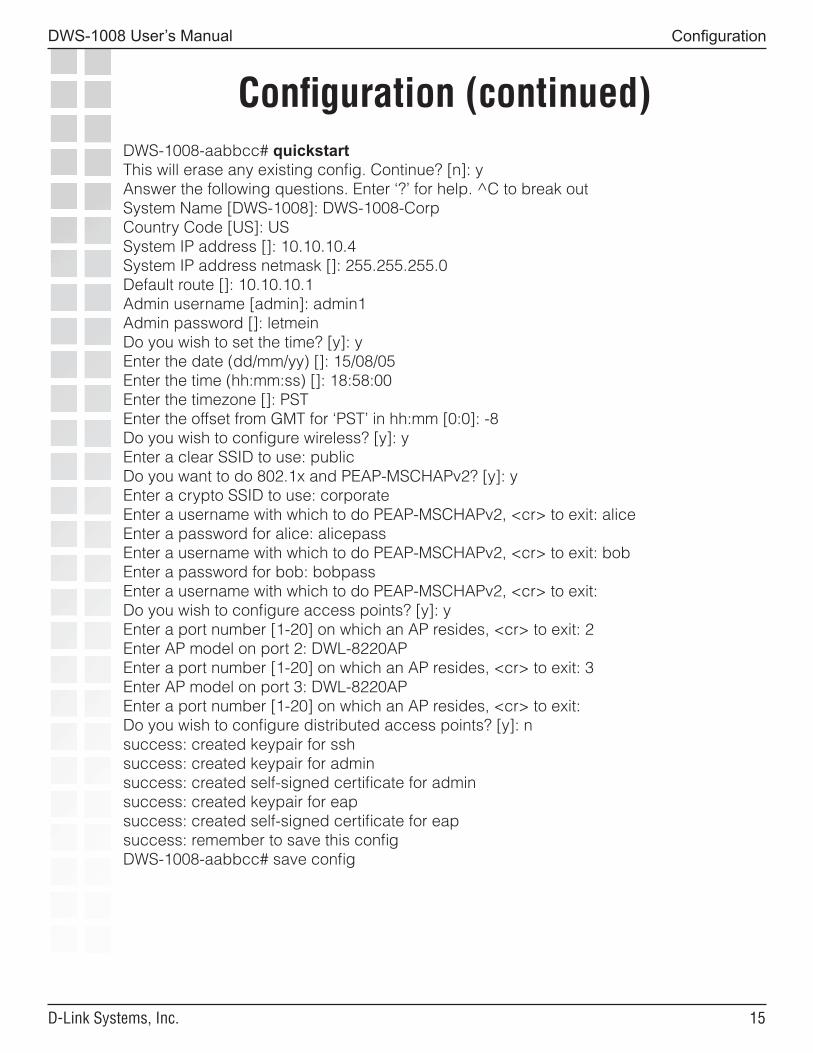
DWS-1008-aabbcc# quickstartThis will erase any existing config. Continue? [n]: yAnswer the following questions. Enter ‘?’ for help. ^C to break outSystem Name [DWS-1008]: DWS-1008-CorpCountry Code [US]: USSystem IP address []: 10.10.10.4System IP address netmask []: 255.255.255.0Default route []: 10.10.10.1Admin username [admin]: admin1Admin password []: letmeinDo you wish to set the time? [y]: yEnter the date (dd/mm/yy) []: 15/08/05Enter the time (hh:mm:ss) []: 18:58:00Enter the timezone []: PSTEnter the offset from GMT for ‘PST’ in hh:mm [0:0]: -8Do you wish to configure wireless? [y]: yEnter a clear SSID to use: publicDo you want to do 802.1x and PEAP-MSCHAPv2? [y]: yEnter a crypto SSID to use: corporateEnter a username with which to do PEAP-MSCHAPv2, <cr> to exit: aliceEnter a password for alice: alicepassEnter a username with which to do PEAP-MSCHAPv2, <cr> to exit: bobEnter a password for bob: bobpassEnter a username with which to do PEAP-MSCHAPv2, <cr> to exit:Do you wish to configure access points? [y]: yEnter a port number [1-20] on which an AP resides, <cr> to exit: 2Enter AP model on port 2: DWL-8220APEnter a port number [1-20] on which an AP resides, <cr> to exit: 3Enter AP model on port 3: DWL-8220APEnter a port number [1-20] on which an AP resides, <cr> to exit:Do you wish to configure distributed access points? [y]: nsuccess: created keypair for sshsuccess: created keypair for adminsuccess: created self-signed certificate for adminsuccess: created keypair for eapsuccess: created self-signed certificate for eapsuccess: remember to save this configDWS-1008-aabbcc# save config
��
DWS-1008 User’s Manual
D-Link Systems, Inc.
Configuration (continued)
Configuration
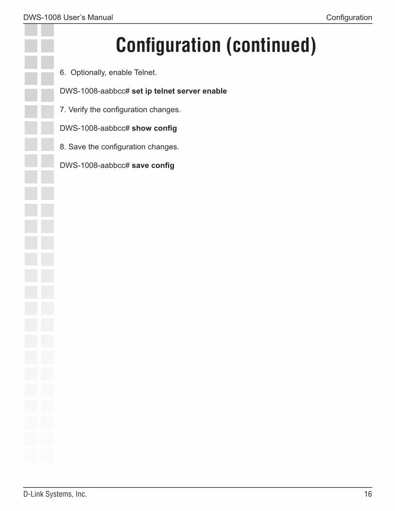
6. Optionally, enable Telnet.
DWS-1008-aabbcc# set ip telnet server enable
7. Verify the configuration changes.
DWS-1008-aabbcc# show config
8. Save the configuration changes.
DWS-1008-aabbcc# save config
��
DWS-1008 User’s Manual
D-Link Systems, Inc.
Configuration (continued)
Configuration
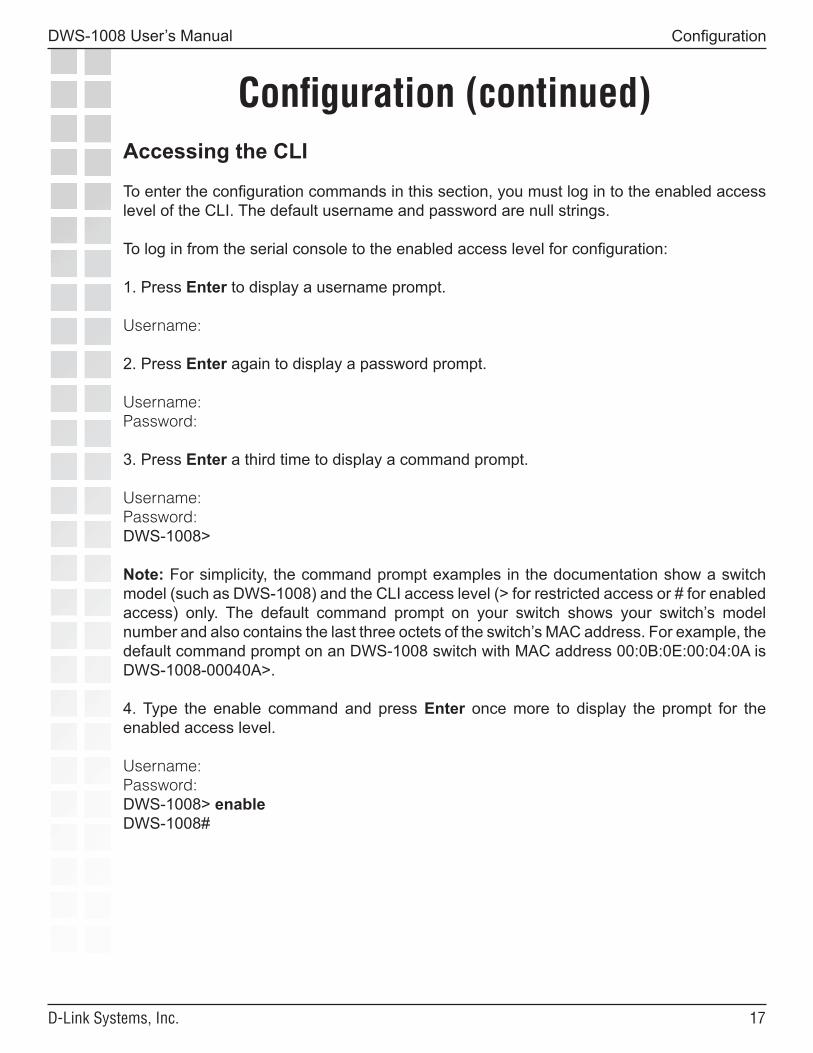
Accessing the CLI
To enter the configuration commands in this section, you must log in to the enabled access level of the CLI. The default username and password are null strings.
To log in from the serial console to the enabled access level for configuration:
1. Press Enter to display a username prompt.
Username:
2. Press Enter again to display a password prompt.
Username:Password:
3. Press Enter a third time to display a command prompt.
Username:Password:DWS-1008>
Note: For simplicity, the command prompt examples in the documentation show a switch model (such as DWS-1008) and the CLI access level (> for restricted access or # for enabled access) only. The default command prompt on your switch shows your switch’s model number and also contains the last three octets of the switch’s MAC address. For example, the default command prompt on an DWS-1008 switch with MAC address 00:0B:0E:00:04:0A is DWS-1008-00040A>.
4. Type the enable command and press Enter once more to display the prompt for the enabled access level.
Username:Password:DWS-1008> enableDWS-1008#
��
DWS-1008 User’s Manual
D-Link Systems, Inc.
Configuration (continued)
Configuration
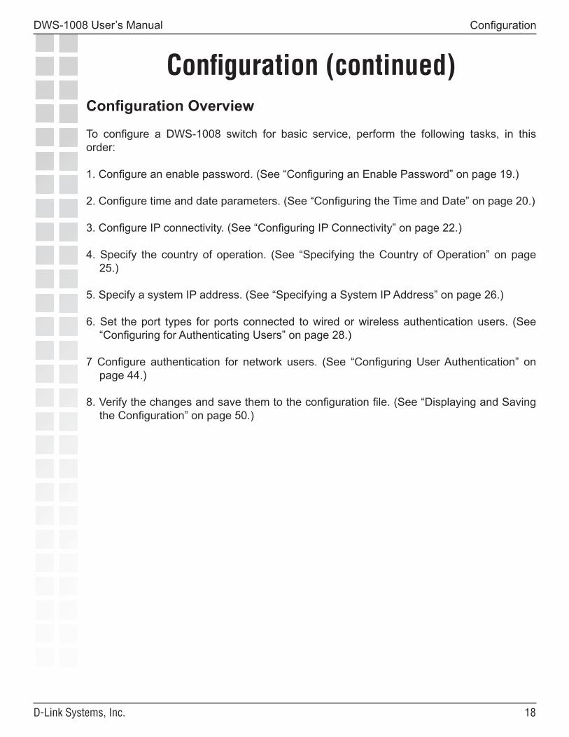
Configuration Overview
To configure a DWS-1008 switch for basic service, perform the following tasks, in this order:
1. Configure an enable password. (See “Configuring an Enable Password” on page 19.)
2. Configure time and date parameters. (See “Configuring the Time and Date” on page 20.)
3. Configure IP connectivity. (See “Configuring IP Connectivity” on page 22.)
4. Specify the country of operation. (See “Specifying the Country of Operation” on page 25.)
5. Specify a system IP address. (See “Specifying a System IP Address” on page 26.)
6. Set the port types for ports connected to wired or wireless authentication users. (See “Configuring for Authenticating Users” on page 28.)
7 Configure authentication for network users. (See “Configuring User Authentication” on page 44.)
8. Verify the changes and save them to the configuration file. (See “Displaying and Saving the Configuration” on page 50.)
��
DWS-1008 User’s Manual
D-Link Systems, Inc.
Configuration (continued)
Configuration
Configuring an Enable Password
D-Link recommends that you configure an enable password to provide at least minimal security to the DWS-1008 switch before you proceed to more advanced configuration options.
To configure an enable password, use the following command:
set enablepass
To configure an enable password:
1. If you are not already at the enabled access level, enter the enable command.
DWS-1008> enable
2. At the enabled prompt, enter set enablepass.
DWS-1008# set enablepass
3. When you are prompted for your old password, press Enter.
Enter old password:
4. When you are prompted for a new password, enter an enable password of up to 32 alphanumeric characters, with no spaces.
Enter new password:
The password you enter is not displayed.
5. When you are prompted to retype your password, reenter the enable password.
Retype new password:
MSS does not display your password, but lets you know that the enable password is set:
success: password changed
�0
DWS-1008 User’s Manual
D-Link Systems, Inc.
Configuration (continued)
Configuration
Configuring the Time and Date
To set the system time and date:
1. Set the time zone to specify the offset from Coordinated Universal Time (UTC).
2. Configure MSS to offset the time by an additional hour for daylight savings time or similar summertime period, if applicable.
3 Specify the IP address of a Network Time Protocol (NTP) server or statically set the time and date.
Note: D-Link recommends that you set the time and date parameters before you install certificates on the DWS-1008 switch. Generally, certificates are valid for one year beginning with the system time and date that are in effect when you generate the certificate request. If the switch’s time and date are incorrect, the certificate might not be valid.
To configure time and date parameters, use the following commands:
set timezone zone-name {-hours [minutes]}
set summertime summer-name [start week weekday month hour min end week weekday month hour min]set timedate {date mmm dd yyyy [time hh:mm:ss]}
set ntp {enable | disable}
set ntp server ip-addr
To verify the changes, use the following commands:
show timezone
show summertime
show timedate
show ntp
The following commands configure the timezone as PST (Pacific Standard Time) with an offset of -8 hours from UTC and enable the standard summertime offset and name it PDT (Pacific Daylight Time).
��
DWS-1008 User’s Manual
D-Link Systems, Inc.
Configuration (continued)
Configuration
Additional commands configure an NTP server and enable the switch’s NTP client.
DWS-1008# set timezone PST -8success: change accepted.
DWS-1008# set summertime PDTsuccess: change accepted.
DWS-1008# set ntp server 192.168.1.10
DWS-1008# set ntp enablesuccess: NTP Client enabled
The following commands display time and date parameters and the current time and date:
DWS-1008# show timezone
Timezone is set to ‘PST’, offset from UTC is -8:0 hours.
DWS-1008# show summertime
Summertime is enabled, and set to ‘PDT’. Start : Sun Apr 04 2004, 02:00:00 End : Sun Oct 31 2004, 02:00:00 Offset : 60 minutes Recurring : yes, starting at 2:00 am of first Sunday of April and ending at 2:00 am on last Sunday of October.
DWS-1008# show ntp
NTP client: enabled Current update-interval: 20(secs) Current time: Fri Feb 06 2004, 12:02:57 Timezone is set to ‘PST’, offset from UTC is -8:0 hours. Summertime is enabled. Last NTP update: Fri Feb 06 2004, 12:02:46NTP Server Peer state Local State-----------------------------------------------------------------------------192.168.1.5 SYSPEER SYNCED
DWS-1008# show timedate
Fri Feb 06 2004, 12:03:04 PST
��
DWS-1008 User’s Manual
D-Link Systems, Inc.
Configuration (continued)
Configuration
Configuring IP Connectivity
To configure IP connectivity:
1. Configure a VLAN, assign a port to the VLAN that can provide IP connectivity through the network for administrative purposes, and configure an IP address on the VLAN. (See “Configuring VLANs and IP Addresses” below.)
2. Configure a default route. (See “Configuring a Default Route” on page 28.)
3. Test the IP configuration. (See “Verifying IP Connectivity” on page 29.)
Configuring VLANs and IP Addresses
Any or all VLANs on the switch can have an IP address. User traffic also requires VLANs, although you do not need to configure every user’s VLAN on every DWS-1008 switch.
To configure a VLAN and an IP address, use the following commands:
set vlan vlan-num name nameset vlan vlan-id port port-list [tag tag-value]set interface vlan-id ip {ip-addr mask | ip-addr/mask-length}
Note: The vlan-id parameter can be the VLAN number or the VLAN name.
To verify the changes, use the following commands:
show vlan configshow interface
The following commands configure a VLAN named mgmt and two additional VLANs over an 802.1Q trunk link for network traffic:
DWS-1008# set vlan 2 name mgmtsuccess: change accepted.DWS-1008# set vlan mgmt port 5success: change accepted.DWS-1008# set vlan 3 name redsuccess: change accepted.DWS-1008# set vlan red port 5 tag 30success: change accepted.DWS-1008# set vlan 4 name bluesuccess: change accepted.DWS-1008# set vlan blue port 5 tag 20success: change accepted.
��
DWS-1008 User’s Manual
D-Link Systems, Inc.
Configuration (continued)
Configuration
Note: To avoid confusion, do not assign numbers as VLAN names. Every VLAN on a DWS-1008 switch has both a VLAN name used for authorization purposes and a VLAN number. VLAN numbers can vary uniquely for each switch and are not related to 802.1Q tag values even when used.
Configuring a Default Route
To configure a default route, use the following command:
set ip route default gateway metric
To verify the change, use the following command:
show ip route
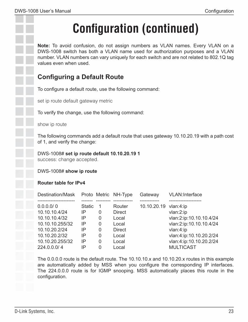
The following commands add a default route that uses gateway 10.10.20.19 with a path cost of 1, and verify the change:
DWS-1008# set ip route default 10.10.20.19 1success: change accepted.
DWS-1008# show ip route
Router table for IPv4
Destination/Mask Proto Metric NH-Type Gateway VLAN:Interface----------------------- ------- --------- ------------ ------------ --------------------0.0.0.0/ 0 Static 1 Router 10.10.20.19 vlan:4:ip10.10.10.4/24 IP 0 Direct vlan:2:ip10.10.10.4/32 IP 0 Local vlan:2:ip:10.10.10.4/2410.10.10.255/32 IP 0 Local vlan:2:ip:10.10.10.4/2410.10.20.2/24 IP 0 Direct vlan:4:ip10.10.20.2/32 IP 0 Local vlan:4:ip:10.10.20.2/2410.10.20.255/32 IP 0 Local vlan:4:ip:10.10.20.2/24224.0.0.0/ 4 IP 0 Local MULTICAST
The 0.0.0.0 route is the default route. The 10.10.10.x and 10.10.20.x routes in this example are automatically added by MSS when you configure the corresponding IP interfaces. The 224.0.0.0 route is for IGMP snooping. MSS automatically places this route in the configuration.
��
DWS-1008 User’s Manual
D-Link Systems, Inc.
Configuration (continued)
Configuration
Verifying IP Connectivity
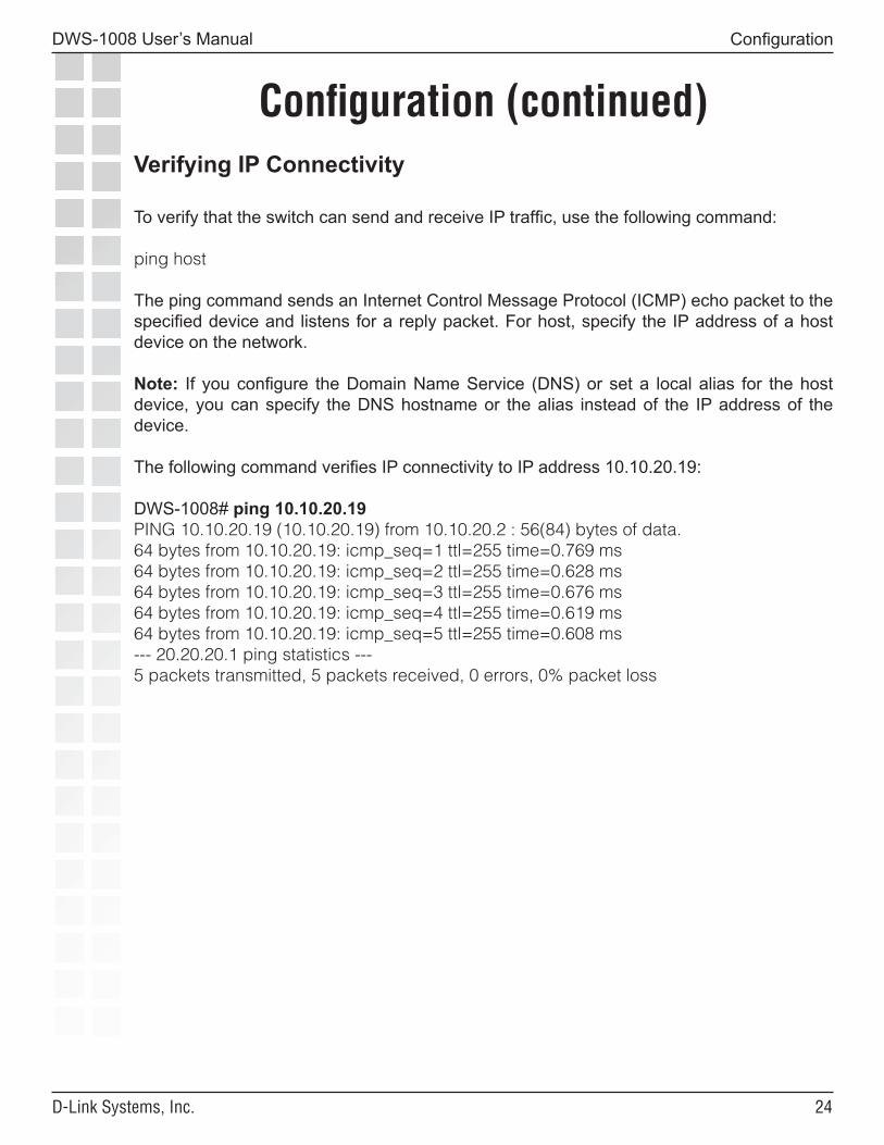
To verify that the switch can send and receive IP traffic, use the following command:
ping host
The ping command sends an Internet Control Message Protocol (ICMP) echo packet to the specified device and listens for a reply packet. For host, specify the IP address of a host device on the network.
Note: If you configure the Domain Name Service (DNS) or set a local alias for the host device, you can specify the DNS hostname or the alias instead of the IP address of the device.
The following command verifies IP connectivity to IP address 10.10.20.19:
DWS-1008# ping 10.10.20.19PING 10.10.20.19 (10.10.20.19) from 10.10.20.2 : 56(84) bytes of data.64 bytes from 10.10.20.19: icmp_seq=1 ttl=255 time=0.769 ms64 bytes from 10.10.20.19: icmp_seq=2 ttl=255 time=0.628 ms64 bytes from 10.10.20.19: icmp_seq=3 ttl=255 time=0.676 ms64 bytes from 10.10.20.19: icmp_seq=4 ttl=255 time=0.619 ms64 bytes from 10.10.20.19: icmp_seq=5 ttl=255 time=0.608 ms--- 20.20.20.1 ping statistics ---5 packets transmitted, 5 packets received, 0 errors, 0% packet loss

��
DWS-1008 User’s Manual
D-Link Systems, Inc.
Configuration (continued)
Configuration
Specifying the Country of Operation
You must specify the country in which you plan to operate the switch and its access points. MSS does not allow you to configure or enable the access point radios until you specify the country of operation.
To specify the country, use the following command:
set system countrycode code
For the country code, specify one of the codes listed below.
Country CodeAustralia AUAustria ATBelgium BEBrazil BRCanada CAChina CNCzech Republic CZDenmark DKFinland FIFrance FRGermany DEGreece GRHong Kong HKHungary HUIceland ISIndia INIreland IEIsrael ILItaly ITJapan JPLiechtenstein LILuxembourg LU
Country CodeMalaysia MYMexico MXNetherlands NLNew Zealand NZNorway NOPoland PLPortugal PTSaudi Arabia SASingapore SGSlovakia SKSlovenia SISouth Africa ZASouth Korea KRSpain ESSweden SESwitzerland CHTaiwan TWThailand THUnited Arab Emirates AEUnited Kingdom GBUnited States US
To verify the configuration change, use the following command:
show system
��
DWS-1008 User’s Manual
D-Link Systems, Inc.
Configuration (continued)
Configuration
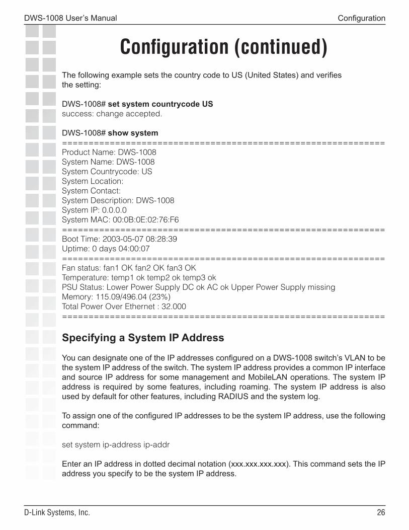
The following example sets the country code to US (United States) and verifiesthe setting:
DWS-1008# set system countrycode USsuccess: change accepted.
DWS-1008# show system=============================================================Product Name: DWS-1008System Name: DWS-1008System Countrycode: USSystem Location:System Contact:System Description: DWS-1008System IP: 0.0.0.0System MAC: 00:0B:0E:02:76:F6=============================================================Boot Time: 2003-05-07 08:28:39Uptime: 0 days 04:00:07=============================================================Fan status: fan1 OK fan2 OK fan3 OKTemperature: temp1 ok temp2 ok temp3 okPSU Status: Lower Power Supply DC ok AC ok Upper Power Supply missingMemory: 115.09/496.04 (23%)Total Power Over Ethernet : 32.000=============================================================
Specifying a System IP Address
You can designate one of the IP addresses configured on a DWS-1008 switch’s VLAN to be the system IP address of the switch. The system IP address provides a common IP interface and source IP address for some management and MobileLAN operations. The system IP address is required by some features, including roaming. The system IP address is also used by default for other features, including RADIUS and the system log.
To assign one of the configured IP addresses to be the system IP address, use the following command:
set system ip-address ip-addr
Enter an IP address in dotted decimal notation (xxx.xxx.xxx.xxx). This command sets the IP address you specify to be the system IP address.
��
DWS-1008 User’s Manual
D-Link Systems, Inc.
Configuration (continued)
Configuration
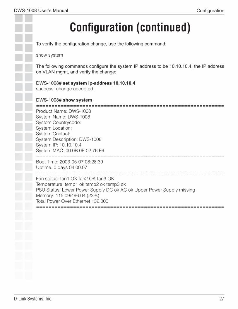
To verify the configuration change, use the following command:
show system
The following commands configure the system IP address to be 10.10.10.4, the IP address on VLAN mgmt, and verify the change:
DWS-1008# set system ip-address 10.10.10.4success: change accepted.
DWS-1008# show system=============================================================Product Name: DWS-1008System Name: DWS-1008System Countrycode:System Location:System Contact:System Description: DWS-1008System IP: 10.10.10.4System MAC: 00:0B:0E:02:76:F6=============================================================Boot Time: 2003-05-07 08:28:39Uptime: 0 days 04:00:07=============================================================Fan status: fan1 OK fan2 OK fan3 OKTemperature: temp1 ok temp2 ok temp3 okPSU Status: Lower Power Supply DC ok AC ok Upper Power Supply missingMemory: 115.09/496.04 (23%)Total Power Over Ethernet : 32.000=============================================================
��
DWS-1008 User’s Manual
D-Link Systems, Inc.
Configuration (continued)
Configuration
Configuring for Authenticating UsersA DWS-1008 switch can provide authentication, authorization, and accounting (AAA) services for wireless and wired users. Wireless users are attached to a switch through an DWL-8220AP access point. Wired users are attached to a switch through wired authentication ports.
By default, all of the switch’s ports are set as wired network ports. Wired network ports connect the switch to other networking devices such as switches and routers.
• To provide authentication to a wired user, you must set that user’s port to be a wired authentication port.
• To provide authentication to wireless users, you must configure the switch to support a DWL-8220AP. How you configure the switch will depend on how the AP is connected to the switch. There are two categories of AP to switch connection: directly connected and distributed.
• A directly connected AP connects to one or two 10/100 ports on a switch. The switch’s 10/100 port provides PoE to the AP. The switch forwards data only to and from the configured AP on that port. The port numbers on the switch configured for direct attached APs reference a particular AP.
• An AP that is not directly connected to a switch is considered a Distributed AP. The switch contains a configuration for a Distributed AP based on the AP’s serial number. Similar to ports configured for directly connected APs, Distributed AP configurations are numbered and can reference a particular AP. These numbered configurations do not, however, reference any physical port.
Note: A Distributed AP is a leaf device. You do not need to enable STP on the port that is directly connected to the AP. If Spanning Tree Protocol (STP) is enabled on the port that is directly connected to a Distributed AP, D-Link recommends that you enable port fast convergence (called PortFast on some vendors’ devices) on the port or disable STP on the port.
Configuring a Port for a Wired Authentication UserA wired authentication user connects to the switch by a network cable. The user must authenticate before connecting to the network. To set a port type for a wired authentication user, use the following command:
set port type wired-auth port-list [tag tag-list] [max-sessions num]
The following example sets port 3 for a wired authentication user:
DWS-1008# set port type wired-auth 3success: change accepted
��
DWS-1008 User’s Manual
D-Link Systems, Inc.
Configuration (continued)
Configuration
Configuring APs for Wireless Users
A wireless user makes a wireless connection through an AP to the switch. The user must authenticate before connecting to the network. To allow wireless users, you must configure the switch to support an AP. To prepare a DWL-8220AP access point for use, perform the following tasks, in this order:
1. Configure the switch for the AP access it will be supporting and enable Power over Ethernet (PoE) if required.
2. Configure a service profile for each SSID and its encryption settings.
3. Configure a radio profile.
4. Apply the radio profile to radios and enable the radios.
AP Connection Requirements
You can connect a DWL-8220AP access point to a DWS-1008 switch directly to a 10/100 port supplying PoE or through an intermediate network. There are two types of AP to switch connection: direct and distributed.
• In direct connection, an AP connects to one or two 10/100 ports on a switch. The switch port is then configured specifically for a direct attachment to an AP. There is no intermediate networking equipment between the switch and AP and only one AP is connected to the switch port. The switch’s 10/100 port provides PoE to the AP. The switch also forwards data only to and from the configured AP on that port. The port numbers on the switch configured for directly attached APs reference a particular AP.
• An AP that is not directly connected to a switch is considered a Distributed AP. There may be intermediate Layer 2 switches or Layer 3 IP routers between the switch and AP. The switch may communicate to the Distributed AP through any network port. (A network port is any port connecting the switch to other networking devices, such as switches and routers, and it can also be configured for 802.1Q VLAN tagging.) The switch contains a configuration for a Distributed AP based on the AP’s serial number. Similar to ports configured for directly connected APs, Distributed AP configurations are numbered and can reference a particular AP. These numbered configurations do not, however, reference any physical port.
�0
DWS-1008 User’s Manual
D-Link Systems, Inc.
Configuration (continued)
Configuration
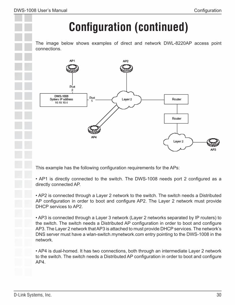
The image below shows examples of direct and network DWL-8220AP access point connections.
This example has the following configuration requirements for the APs:
• AP1 is directly connected to the switch. The DWS-1008 needs port 2 configured as a directly connected AP.
• AP2 is connected through a Layer 2 network to the switch. The switch needs a Distributed AP configuration in order to boot and configure AP2. The Layer 2 network must provide DHCP services to AP2.
• AP3 is connected through a Layer 3 network (Layer 2 networks separated by IP routers) to the switch. The switch needs a Distributed AP configuration in order to boot and configure AP3. The Layer 2 network that AP3 is attached to must provide DHCP services. The network’s DNS server must have a wlan-switch.mynetwork.com entry pointing to the DWS-1008 in the network.
• AP4 is dual-homed. It has two connections, both through an intermediate Layer 2 network to the switch. The switch needs a Distributed AP configuration in order to boot and configure AP4.
��
DWS-1008 User’s Manual
D-Link Systems, Inc.
Configuration (continued)
Configuration
The following sections list the configuration requirements for direct attached APs and Distributed APs.
Local Connection Requirements
When an AP connects directly to a switch’s 10/100 port, the switch’s port must be configured as a DWL-8220AP access port, which supports AP traffic only. There is no intermediate networking equipment between the switch and AP and only one AP is connected to the switch port. The switch’s 10/100 port provides PoE to the AP. The switch forwards data only to and from the configured AP on that port.
Distributed AP Network Requirements
When an AP connects indirectly to a switch, the switch must be configured with a Distributed AP configuration. The switch can communicate with the Distributed AP through any network port. (In the CLI, a Distributed AP configuration is referred to as a DAP.)
Because distributed APs are not directly attached to a DWS-1008 switch, they require additional support from the network in order to function.
• Power - PoE must be provided on one of the Ethernet connections to the AP. Be sure to utilize a PoE injection device that has been tested by D-Link. Providing PoE on both of the Ethernet connections (if the AP has two) allows for redundant PoE.
• DHCP - A Distributed AP uses TCP/IP for communication, and relies on DHCP to obtain IP parameters. Therefore, DHCP services must be available on the subnet that the AP is connected to. DHCP must provide the following parameters to the AP:
• IP address • DNS server address • Gateway address
Optionally, the Offer message can also contain a list of switch IP addresses or hostnames, in the option 43 field of the DHCP message.
��
DWS-1008 User’s Manual
D-Link Systems, Inc.
Configuration (continued)
Configuration
DNS - If the intermediate network between the switch and Distributed AP includes one or more IP routers, create a TRPZ.mynetwork.com or wlan-switch.mynetwork.com entry on the DNS server. The entry needs to map one of these names to the system IP address of the switch.
The DNS entry allows the AP to communicate with a switch that is not on the AP’s subnet. If the AP is unable to locate a switch on the subnet it is connected to, the AP sends DNS requests to both TRPZ and wlan-switch, where the DNS suffix for mynetwork.com is learned through DHCP.
• If only TRPZ is defined in DNS, the AP contacts the switch whose IP address is returned for TRPZ.
• If only wlan-switch is defined in DNS, the AP contacts the switch whose IP address is returned for wlan-switch.
• If both TRPZ and wlan-switch are defined in DNS, the AP contacts the switch whose IP address is returned for TRPZ. The AP ignores the IP address returned for wlan-switch.
• If both TRPZ and wlan-switch are defined in DNS, and the AP is unable to contact the IP address returned for TRPZ, the AP never contacts the IP address returned for wlan-switch. The AP does not boot.
After the AP contacts the switch, the switch relays information about DWS-1008 switches in the network that contain a Distributed AP configuration specific to that Distributed AP.
Caution: Do not enable PoE on network ports unless you intend to power a third-party device. If you enable PoE under other conditions, power can damage the device.
��
DWS-1008 User’s Manual
D-Link Systems, Inc.
Configuration (continued)
Configuration
Configuring for a Directly-Connected AP
Caution: When you set the port type for use by locally connected APs, you must specify the PoE state (enabled or disabled) of the port. If you enable PoE on a port connected to another device, physical damage to the device can result.
To set a port for a locally-connected AP, use the following command:
set port type ap port-listmodel {DWL-8220AP}poe {enable | disable}[radiotype {11a | 11b| 11g}]
You must specify a port list of one or more port numbers, the AP model number, and the PoE state.
DWL-8220AP access points have a two radios; One radio is always 802.11a. The other radio is 802.11b/g, but can be configured for 802.11b or 802.11g exclusively. If the country of operation specified by the set system countrycode command does not allow 802.11g, the default is 802.11b.
DWL-8220AP radios configured for 802.11g also allow associations from 802.11b clients by default. To disable support for 802.11b associations, use the set radio-profile 11g-only command on the radio profile that contains the radio.
The DWL-8220AP has an internal 802.1b/g antenna as well as a connector for an external antenna, so use of an external antenna is optional on these models. It also has a connector for an optional external 802.11a antenna. To specify the antenna model, use the set {ap | dap} radio antennatype command.
To verify the configuration changes, use the following commands. Use show ap config for directly connected APs and use show dap config for Distributed APs.
show ap config [port-list [radio {1 | 2}]]show dap config [dap-num [radio {1 | 2}]]
��
DWS-1008 User’s Manual
D-Link Systems, Inc.
Configuration (continued)
Configuration
The following example sets ports 1, 2, and 4 for the DWL-8220AP access point:
DWS-1008# set port type ap 1,2,4 model dwl-8220ap poe enable
This may affect the power applied on the configured ports.Would you like to continue? (y/n) [n]ysuccess: change accepted.
To verify the configuration change, use the following command:
show ap config [port-list [radio {1 | 2}]]
Here is an example:
DWS-1008# show ap config 1Port 1: AP model: dwl-8220ap, POE: enable, bias: high, name: AP01boot-download-enable: YESload balancing group: noneRadio 1: type: 802.11g, mode: disabled, channel: 6tx pwr: 15, profile: defaultauto-tune max-power: default, min-client-rate: 5.5, max-retransmissions: 10Radio 2: type: 802.11a, mode: disabled, channel: 36tx pwr: 11, profile: defaultauto-tune max-power: default, min-client-rate: 24, max-retransmissions: 10
Configuring for a Distributed AP
To create a configuration for a Distributed AP (referred to as a DAP in the CLI), use the following command:
set dap dap-num serial-id serial-IDmodel {DWL8220AP}[radiotype {11a | 11b| 11g}]
The dap-num parameter identifies the Distributed AP connection for the AP. The range of valid connection ID numbers is from 1 to 30.
For the serial-id parameter, specify the serial ID of the AP. The serial ID is listed on the AP case. To display the serial ID using the CLI, use the show version details command. The model and radiotype parameters have the same options as they do with the set port type ap command. Because the switch does not supply power to an indirectly connected AP, the set dap command does not use the poe parameter.
��
DWS-1008 User’s Manual
D-Link Systems, Inc.
Configuration (continued)
Configuration
Note: You can configure an AP configuration template for automatically configuring Distributed APs when they boot using the DWS-1008 switch.
The following example configures connections for two Distributed APs that are indirectly connected to the switch. Note that when you create a connection, you assign it a number that can be used later for displaying and configuration, much like the physical ports for directly connected APs:
DWS-1008# set dap 1 serial-id 0322199999 model dwl-8220apsuccess: change accepted.
DWS-1008# set dap 2 serial-id 0322199998 model dwl-8220apsuccess: change accepted.
To verify the configuration change, use the following command:
show dap config [dap-num [radio {1 | 2}]]
Here is an example:
DWS-1008# show dap configDap 1: serial-id: 0322199999, AP model: dwl-8220ap, bias: high, name: DAP01fingerprint:boot-download-enable: YESload balancing group: noneRadio 1: type: 802.11g, mode: disabled, channel: dynamictx pwr: 14, profile: defaultauto-tune max-power: default, min-client-rate: 5.5, max-retransmissions: 10Radio 2: type: 802.11a, mode: disabled, channel: dynamictx pwr: 11, profile: defaultauto-tune max-power: default, min-client-rate: 24, max-retransmissions: 10
Dap 2: serial-id: 0322199998, AP model: dwl-8220ap, bias: high, name: DAP02fingerprint:boot-download-enable: YESload balancing group: noneRadio 1: type: 802.11g, mode: disabled, channel: dynamictx pwr: 14, profile: defaultauto-tune max-power: default, min-client-rate: 5.5, max-retransmissions: 10Radio 2: type: 802.11a, mode: disabled, channel: dynamictx pwr: 11, profile: defaultauto-tune max-power: default, min-client-rate: 24, max-retransmissions: 10
��
DWS-1008 User’s Manual
D-Link Systems, Inc.
Configuration (continued)
Configuration
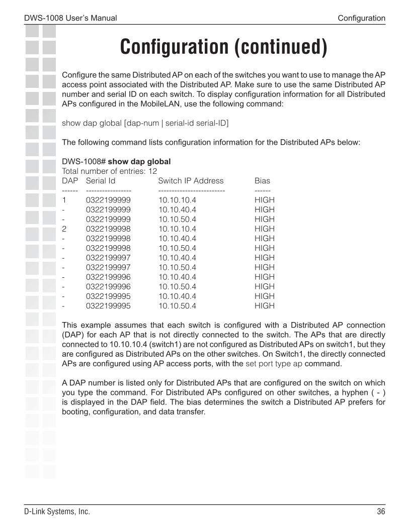
Configure the same Distributed AP on each of the switches you want to use to manage the AP access point associated with the Distributed AP. Make sure to use the same Distributed AP number and serial ID on each switch. To display configuration information for all Distributed APs configured in the MobileLAN, use the following command:
show dap global [dap-num | serial-id serial-ID]
The following command lists configuration information for the Distributed APs below:
DWS-1008# show dap globalTotal number of entries: 12DAP Serial Id Switch IP Address Bias------ ----------------- ------------------------- ------1 0322199999 10.10.10.4 HIGH- 0322199999 10.10.40.4 HIGH- 0322199999 10.10.50.4 HIGH2 0322199998 10.10.10.4 HIGH- 0322199998 10.10.40.4 HIGH- 0322199998 10.10.50.4 HIGH- 0322199997 10.10.40.4 HIGH- 0322199997 10.10.50.4 HIGH- 0322199996 10.10.40.4 HIGH- 0322199996 10.10.50.4 HIGH- 0322199995 10.10.40.4 HIGH- 0322199995 10.10.50.4 HIGH
This example assumes that each switch is configured with a Distributed AP connection (DAP) for each AP that is not directly connected to the switch. The APs that are directly connected to 10.10.10.4 (switch1) are not configured as Distributed APs on switch1, but they are configured as Distributed APs on the other switches. On Switch1, the directly connected APs are configured using AP access ports, with the set port type ap command.
A DAP number is listed only for Distributed APs that are configured on the switch on which you type the command. For Distributed APs configured on other switches, a hyphen ( - ) is displayed in the DAP field. The bias determines the switch a Distributed AP prefers for booting, configuration, and data transfer.
��
DWS-1008 User’s Manual
D-Link Systems, Inc.
Configuration (continued)
Configuration
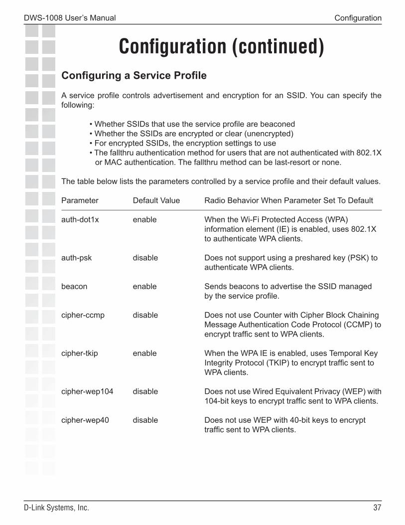
Configuring a Service Profile
A service profile controls advertisement and encryption for an SSID. You can specify the following:
• Whether SSIDs that use the service profile are beaconed• Whether the SSIDs are encrypted or clear (unencrypted)• For encrypted SSIDs, the encryption settings to use• The fallthru authentication method for users that are not authenticated with 802.1X
or MAC authentication. The fallthru method can be last-resort or none.
The table below lists the parameters controlled by a service profile and their default values.
Parameter Default Value Radio Behavior When Parameter Set To Default
auth-dot1x enable When the Wi-Fi Protected Access (WPA) information element (IE) is enabled, uses 802.1X to authenticate WPA clients.
auth-psk disable Does not support using a preshared key (PSK) to authenticate WPA clients.
beacon enable Sends beacons to advertise the SSID managed by the service profile.
cipher-ccmp disable Does not use Counter with Cipher Block Chaining Message Authentication Code Protocol (CCMP) to encrypt traffic sent to WPA clients.
cipher-tkip enable When the WPA IE is enabled, uses Temporal Key Integrity Protocol (TKIP) to encrypt traffic sent to WPA clients.
cipher-wep104 disable Does not use Wired Equivalent Privacy (WEP) with 104-bit keys to encrypt traffic sent to WPA clients.
cipher-wep40 disable Does not use WEP with 40-bit keys to encrypt traffic sent to WPA clients.
��
DWS-1008 User’s Manual
D-Link Systems, Inc.
Configuration (continued)
Configuration
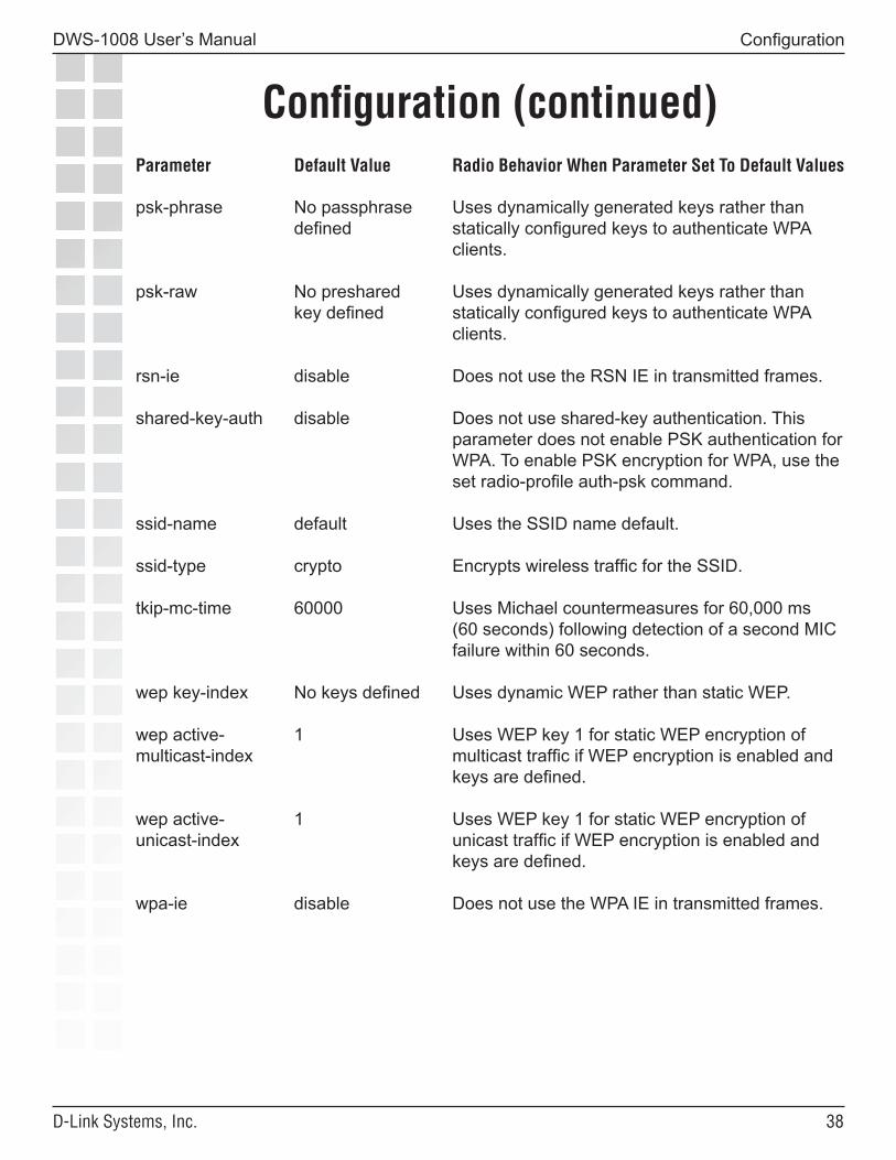
Parameter Default Value Radio Behavior When Parameter Set To Default Values
psk-phrase No passphrase Uses dynamically generated keys rather than defined statically configured keys to authenticate WPA clients.
psk-raw No preshared Uses dynamically generated keys rather than key defined statically configured keys to authenticate WPA clients.
rsn-ie disable Does not use the RSN IE in transmitted frames.
shared-key-auth disable Does not use shared-key authentication. This parameter does not enable PSK authentication for WPA. To enable PSK encryption for WPA, use the set radio-profile auth-psk command.
ssid-name default Uses the SSID name default.
ssid-type crypto Encrypts wireless traffic for the SSID.
tkip-mc-time 60000 Uses Michael countermeasures for 60,000 ms (60 seconds) following detection of a second MIC failure within 60 seconds.
wep key-index No keys defined Uses dynamic WEP rather than static WEP.
wep active- 1 Uses WEP key 1 for static WEP encryption ofmulticast-index multicast traffic if WEP encryption is enabled and keys are defined.
wep active- 1 Uses WEP key 1 for static WEP encryption ofunicast-index unicast traffic if WEP encryption is enabled and keys are defined.
wpa-ie disable Does not use the WPA IE in transmitted frames.
��
DWS-1008 User’s Manual
D-Link Systems, Inc.
Configuration (continued)
Configuration
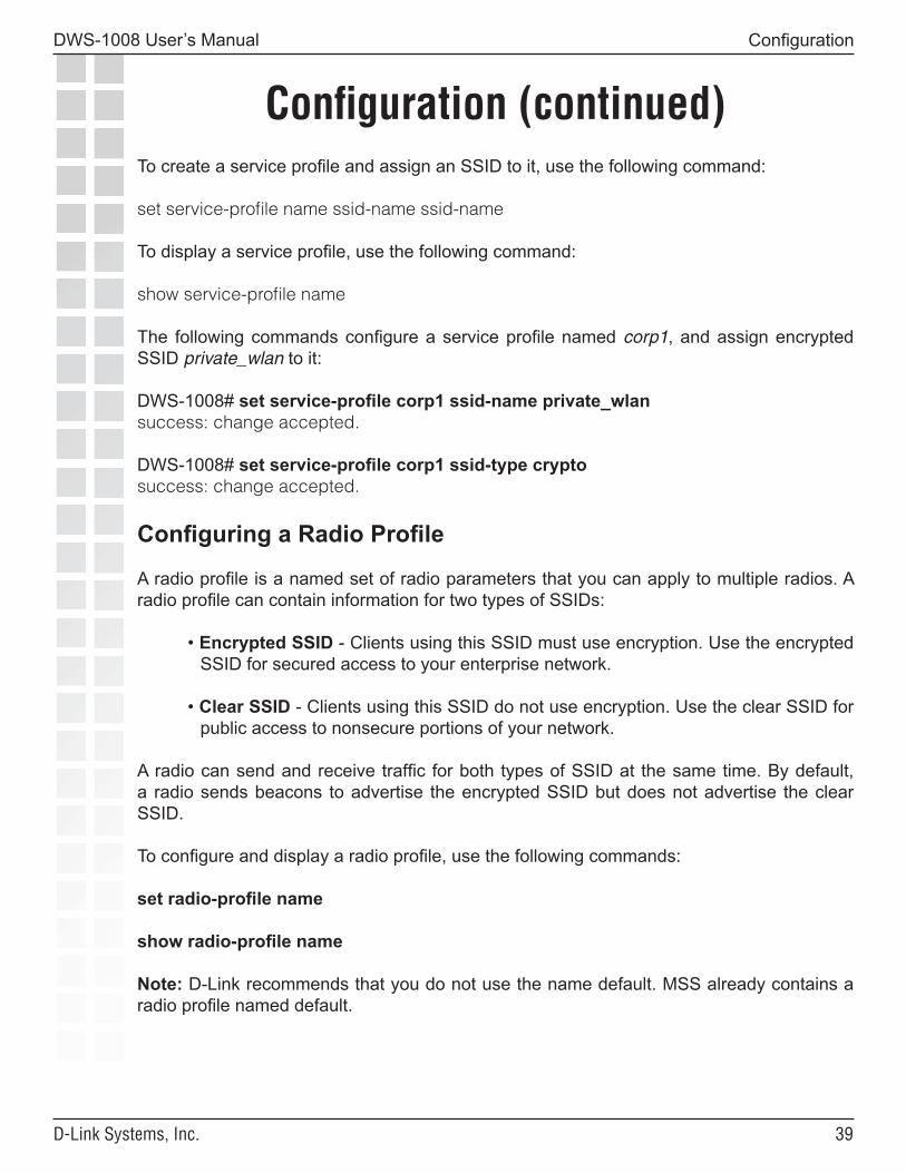
To create a service profile and assign an SSID to it, use the following command:
set service-profile name ssid-name ssid-name
To display a service profile, use the following command:
show service-profile name
The following commands configure a service profile named corp1, and assign encrypted SSID private_wlan to it:
DWS-1008# set service-profile corp1 ssid-name private_wlansuccess: change accepted.
DWS-1008# set service-profile corp1 ssid-type cryptosuccess: change accepted.
Configuring a Radio Profile
A radio profile is a named set of radio parameters that you can apply to multiple radios. A radio profile can contain information for two types of SSIDs:
• Encrypted SSID - Clients using this SSID must use encryption. Use the encrypted SSID for secured access to your enterprise network.
• Clear SSID - Clients using this SSID do not use encryption. Use the clear SSID for public access to nonsecure portions of your network.
A radio can send and receive traffic for both types of SSID at the same time. By default, a radio sends beacons to advertise the encrypted SSID but does not advertise the clear SSID.
To configure and display a radio profile, use the following commands:
set radio-profile name
show radio-profile name
Note: D-Link recommends that you do not use the name default. MSS already contains a radio profile named default.
�0
DWS-1008 User’s Manual
D-Link Systems, Inc.
Configuration (continued)
Configuration
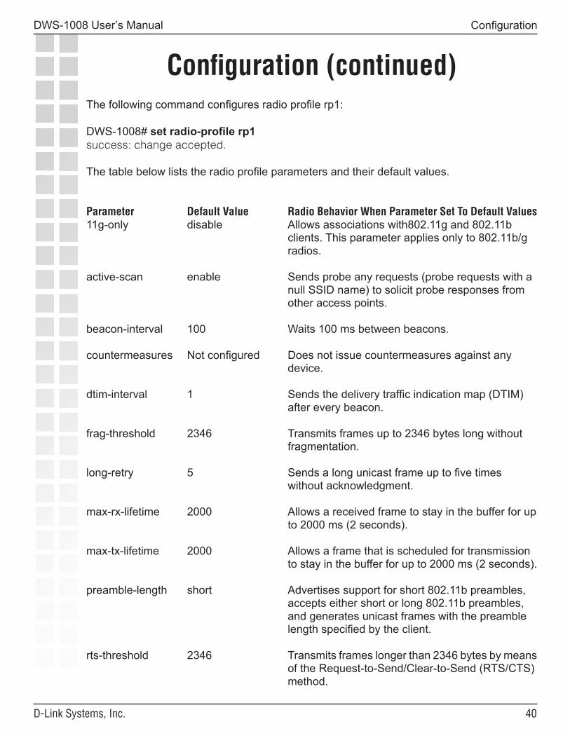
The following command configures radio profile rp1:
DWS-1008# set radio-profile rp1success: change accepted.
The table below lists the radio profile parameters and their default values.
Parameter Default Value Radio Behavior When Parameter Set To Default Values11g-only disable Allows associations with802.11g and 802.11b clients. This parameter applies only to 802.11b/g radios.
active-scan enable Sends probe any requests (probe requests with a null SSID name) to solicit probe responses from other access points.
beacon-interval 100 Waits 100 ms between beacons.
countermeasures Not configured Does not issue countermeasures against any device.
dtim-interval 1 Sends the delivery traffic indication map (DTIM) after every beacon.
frag-threshold 2346 Transmits frames up to 2346 bytes long without fragmentation.
long-retry 5 Sends a long unicast frame up to five times without acknowledgment.
max-rx-lifetime 2000 Allows a received frame to stay in the buffer for up to 2000 ms (2 seconds).
max-tx-lifetime 2000 Allows a frame that is scheduled for transmission to stay in the buffer for up to 2000 ms (2 seconds).
preamble-length short Advertises support for short 802.11b preambles, accepts either short or long 802.11b preambles, and generates unicast frames with the preamble length specified by the client.
rts-threshold 2346 Transmits frames longer than 2346 bytes by means of the Request-to-Send/Clear-to-Send (RTS/CTS) method.
��
DWS-1008 User’s Manual
D-Link Systems, Inc.
Configuration (continued)
Configuration
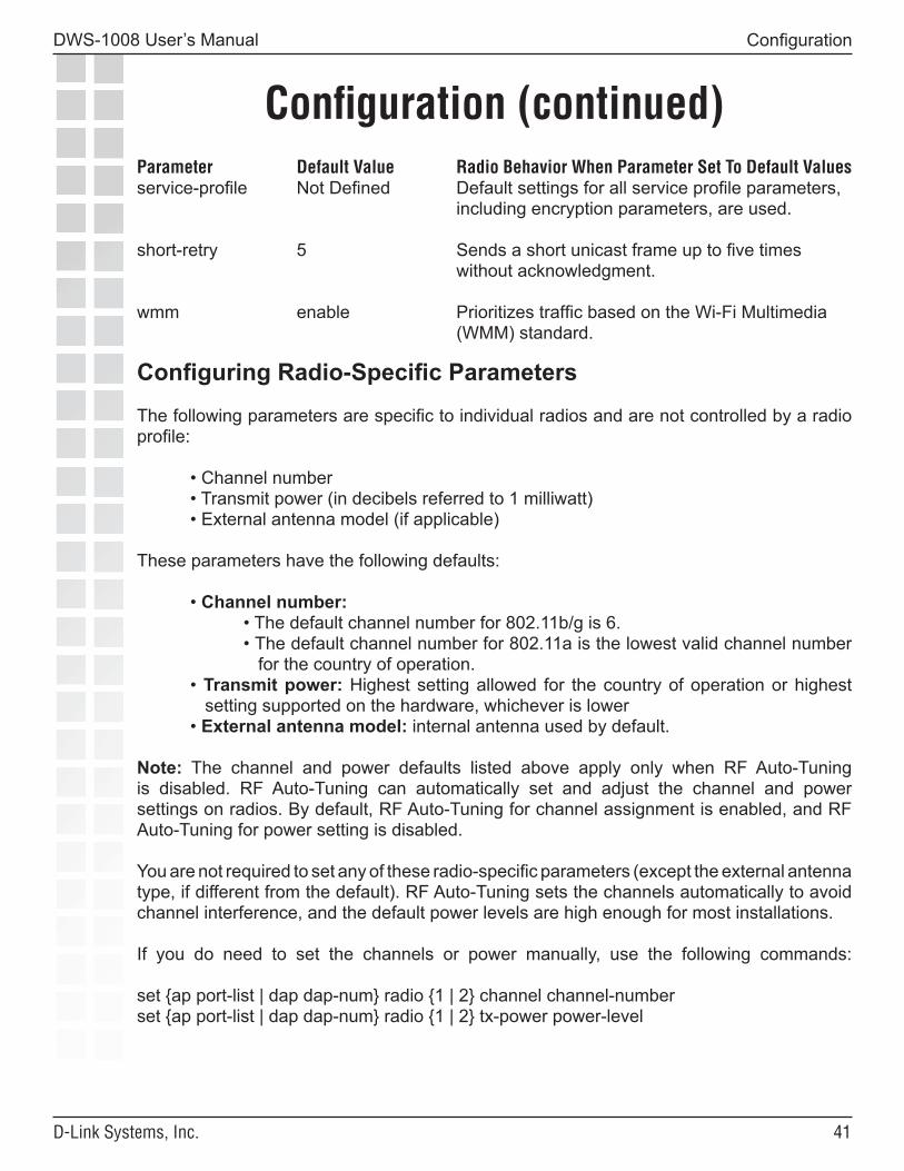
Parameter Default Value Radio Behavior When Parameter Set To Default Valuesservice-profile Not Defined Default settings for all service profile parameters, including encryption parameters, are used.
short-retry 5 Sends a short unicast frame up to five times without acknowledgment.
wmm enable Prioritizes traffic based on the Wi-Fi Multimedia (WMM) standard.
Configuring Radio-Specific Parameters
The following parameters are specific to individual radios and are not controlled by a radio profile:
• Channel number • Transmit power (in decibels referred to 1 milliwatt) • External antenna model (if applicable)
These parameters have the following defaults:
• Channel number: • The default channel number for 802.11b/g is 6. • The default channel number for 802.11a is the lowest valid channel number for the country of operation. • Transmit power: Highest setting allowed for the country of operation or highest setting supported on the hardware, whichever is lower • External antenna model: internal antenna used by default.
Note: The channel and power defaults listed above apply only when RF Auto-Tuning is disabled. RF Auto-Tuning can automatically set and adjust the channel and power settings on radios. By default, RF Auto-Tuning for channel assignment is enabled, and RF Auto-Tuning for power setting is disabled.
You are not required to set any of these radio-specific parameters (except the external antenna type, if different from the default). RF Auto-Tuning sets the channels automatically to avoid channel interference, and the default power levels are high enough for most installations.
If you do need to set the channels or power manually, use the following commands:
set {ap port-list | dap dap-num} radio {1 | 2} channel channel-numberset {ap port-list | dap dap-num} radio {1 | 2} tx-power power-level
��
DWS-1008 User’s Manual
D-Link Systems, Inc.
Configuration (continued)
Configuration
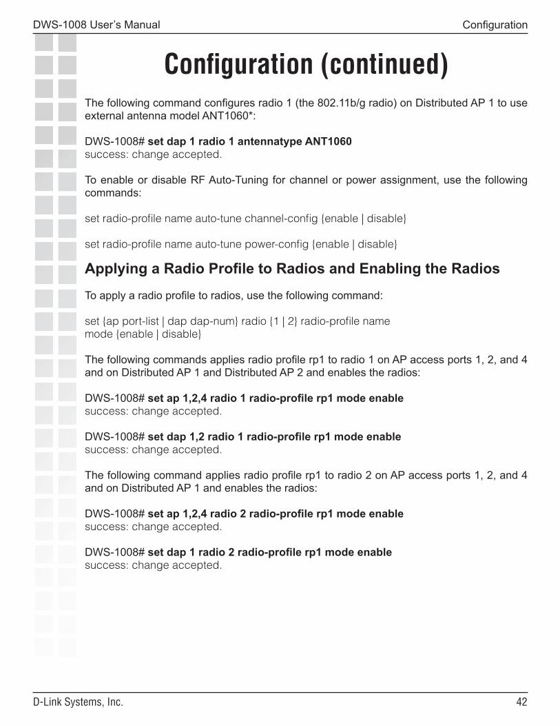
The following command configures radio 1 (the 802.11b/g radio) on Distributed AP 1 to use external antenna model ANT1060*:
DWS-1008# set dap 1 radio 1 antennatype ANT1060success: change accepted.
To enable or disable RF Auto-Tuning for channel or power assignment, use the following commands:
set radio-profile name auto-tune channel-config {enable | disable}
set radio-profile name auto-tune power-config {enable | disable}
Applying a Radio Profile to Radios and Enabling the Radios
To apply a radio profile to radios, use the following command:
set {ap port-list | dap dap-num} radio {1 | 2} radio-profile namemode {enable | disable}
The following commands applies radio profile rp1 to radio 1 on AP access ports 1, 2, and 4 and on Distributed AP 1 and Distributed AP 2 and enables the radios:
DWS-1008# set ap 1,2,4 radio 1 radio-profile rp1 mode enablesuccess: change accepted.
DWS-1008# set dap 1,2 radio 1 radio-profile rp1 mode enablesuccess: change accepted.
The following command applies radio profile rp1 to radio 2 on AP access ports 1, 2, and 4 and on Distributed AP 1 and enables the radios:
DWS-1008# set ap 1,2,4 radio 2 radio-profile rp1 mode enablesuccess: change accepted.
DWS-1008# set dap 1 radio 2 radio-profile rp1 mode enablesuccess: change accepted.

��
DWS-1008 User’s Manual
D-Link Systems, Inc.
Configuration (continued)
Configuration
Here is an example:
DWS-1008# show ap config 1
Port 1: AP model: dwl-8220ap, POE: enable, bias: high, name: AP01boot-download-enable: YESload balancing group: noneRadio 1: type: 802.11g, mode: disabled, channel: 6tx pwr: 15, profile: defaultauto-tune max-power: default, min-client-rate: 5.5, max-retransmissions: 10Radio 2: type: 802.11a, mode: disabled, channel: 36tx pwr: 11, profile: defaultauto-tune max-power: default, min-client-rate: 24, max-retransmissions: 10
Displaying Radio Configuration Information
To verify radio configuration changes, use the following commands:
show ap config [port-list [radio {1 | 2}]]show dap config [dap-num [radio {1 | 2}]]
* Please contact D-Link Sales for information regarding Trapeze antennas.

��
DWS-1008 User’s Manual
D-Link Systems, Inc.
Configuration (continued)
Configuration
Configuring User Authentication
MSS provides the following types of authentication:
• IEEE 802.1X - If the network user’s network interface card (NIC) supports 802.1X, MSS checks for an 802.1X authentication rule that matches the username (and SSID, if wireless access is requested), and that uses the Extensible Authentication Protocol (EAP) requested by the NIC. If a matching rule is found, MSS uses the requested EAP to check the RADIUS server group or local database for the username and password entered by the user. If matching information is found, MSS grants access to the user.
• MAC - If the username does not match an 802.1X authentication rule, but the MAC address of the user’s NIC or Voice-over-IP (VoIP) phone and the SSID (if wireless) do match a MAC authentication rule, MSS checks the RADIUS server group or local database for matching user information. If the MAC address (and password, if on a RADIUS server) matches, MSS grants access. Otherwise, MSS attempts the fallthru authentication type, which can be last-resort or none.
• Last-resort - A network user requests access to the network, without entering a username or password. MSS checks for a last-resort authentication rule for the requested SSID (or for wired, if the user is on a wired authentication port). If a matching rule is found, MSS checks the RADIUS server group or local database for username last-resort-wired (for wired authentication access) or last-resort-ssid, where ssid is the SSID requested by the user. If the user information is on a RADIUS server, MSS also checks for a password.
Users cannot access the network unless they are authorized. You can configure an switch to authenticate users with user information on a group of RADIUS servers or in a local user database on the switch. You also can configure a switch to offload some authentication tasks from the server group.
• Pass-through—The switch establishes an Extensible Authentication Protocol (EAP) session directly between the client and RADIUS server. All authentication information and certificate exchanges pass through the switch. In this case, the switch does not need a certificate.
��
DWS-1008 User’s Manual
D-Link Systems, Inc.
Configuration (continued)
Configuration
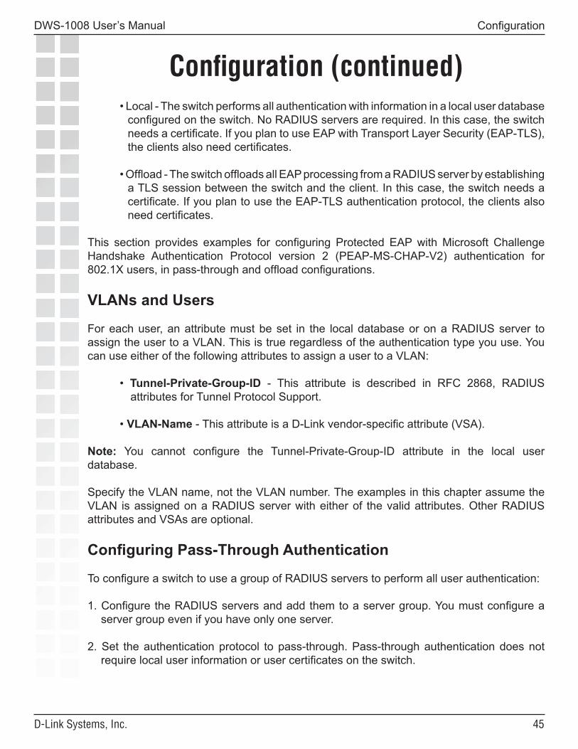
• Local - The switch performs all authentication with information in a local user database configured on the switch. No RADIUS servers are required. In this case, the switch needs a certificate. If you plan to use EAP with Transport Layer Security (EAP-TLS), the clients also need certificates.
• Offload - The switch offloads all EAP processing from a RADIUS server by establishing a TLS session between the switch and the client. In this case, the switch needs a certificate. If you plan to use the EAP-TLS authentication protocol, the clients also need certificates.
This section provides examples for configuring Protected EAP with Microsoft Challenge Handshake Authentication Protocol version 2 (PEAP-MS-CHAP-V2) authentication for 802.1X users, in pass-through and offload configurations.
VLANs and Users
For each user, an attribute must be set in the local database or on a RADIUS server to assign the user to a VLAN. This is true regardless of the authentication type you use. You can use either of the following attributes to assign a user to a VLAN:
• Tunnel-Private-Group-ID - This attribute is described in RFC 2868, RADIUS attributes for Tunnel Protocol Support.
• VLAN-Name - This attribute is a D-Link vendor-specific attribute (VSA).
Note: You cannot configure the Tunnel-Private-Group-ID attribute in the local user database.
Specify the VLAN name, not the VLAN number. The examples in this chapter assume the VLAN is assigned on a RADIUS server with either of the valid attributes. Other RADIUS attributes and VSAs are optional.
Configuring Pass-Through Authentication
To configure a switch to use a group of RADIUS servers to perform all user authentication:
1. Configure the RADIUS servers and add them to a server group. You must configure a server group even if you have only one server.
2. Set the authentication protocol to pass-through. Pass-through authentication does not require local user information or user certificates on the switch.

��
DWS-1008 User’s Manual
D-Link Systems, Inc.
Configuration (continued)
Configuration
Configuring RADIUS Servers for Pass-Through Authentication
To configure MSS to use a RADIUS server, use the following command:
set radius server {server-name} [address ip-addr] [auth-port port-number] [acct-port port-number] [timeout seconds] [retransmit number] [deadtime minutes] [key string] [author-password password]
To add the server(s) to a server group, use the following command:
set server group group-name members server-name1 [server-name2] [server-name3] [server-name4]
To configure MSS to load-balance authentication requests among the servers, use the following command:
set server group group-name load-balance enable | disable
To verify the change, use the following command:
show aaa
The following commands configure two RADIUS servers, add them to server group grp1, enable load balancing of authentication sessions among the servers, and verify the change:
DWS-1008# set radius server svr1 address 10.10.70.20 key rad1pwordsuccess: change accepted.
DWS-1008# set radius server svr2 address 10.10.70.40 key rad2pwordsuccess: change accepted.
DWS-1008# set server group grp1 members svr1 svr2success: change accepted.
DWS-1008# set server group grp1 load-balance enablesuccess: change accepted.
��
DWS-1008 User’s Manual
D-Link Systems, Inc.
Configuration (continued)
Configuration
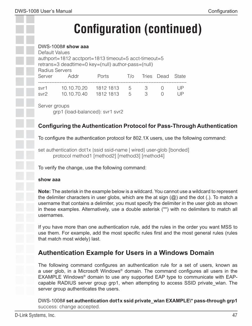
DWS-1008# show aaaDefault Valuesauthport=1812 acctport=1813 timeout=5 acct-timeout=5retrans=3 deadtime=0 key=(null) author-pass=(null)Radius ServersServer Addr Ports T/o Tries Dead State------------------------------------------------------------------------------------------svr1 10.10.70.20 1812 1813 5 3 0 UPsvr2 10.10.70.40 1812 1813 5 3 0 UP
Server groups grp1 (load-balanced): svr1 svr2
Configuring the Authentication Protocol for Pass-Through Authentication
To configure the authentication protocol for 802.1X users, use the following command:
set authentication dot1x {ssid ssid-name | wired} user-glob [bonded] protocol method1 [method2] [method3] [method4]
To verify the change, use the following command:
show aaa
Note: The asterisk in the example below is a wildcard. You cannot use a wildcard to represent the delimiter characters in user globs, which are the at sign (@) and the dot (.). To match a username that contains a delimiter, you must specify the delimiter in the user glob as shown in these examples. Alternatively, use a double asterisk (**) with no delimiters to match all usernames.
If you have more than one authentication rule, add the rules in the order you want MSS to use them. For example, add the most specific rules first and the most general rules (rules that match most widely) last.
Authentication Example for Users in a Windows Domain
The following command configures an authentication rule for a set of users, known as a user glob, in a Microsoft Windows® domain. The command configures all users in the EXAMPLE Windows® domain to use any supported EAP type to communicate with EAP-capable RADIUS server group grp1, when attempting to access SSID private_wlan. The server group authenticates the users.
DWS-1008# set authentication dot1x ssid private_wlan EXAMPLE\* pass-through grp1 success: change accepted.
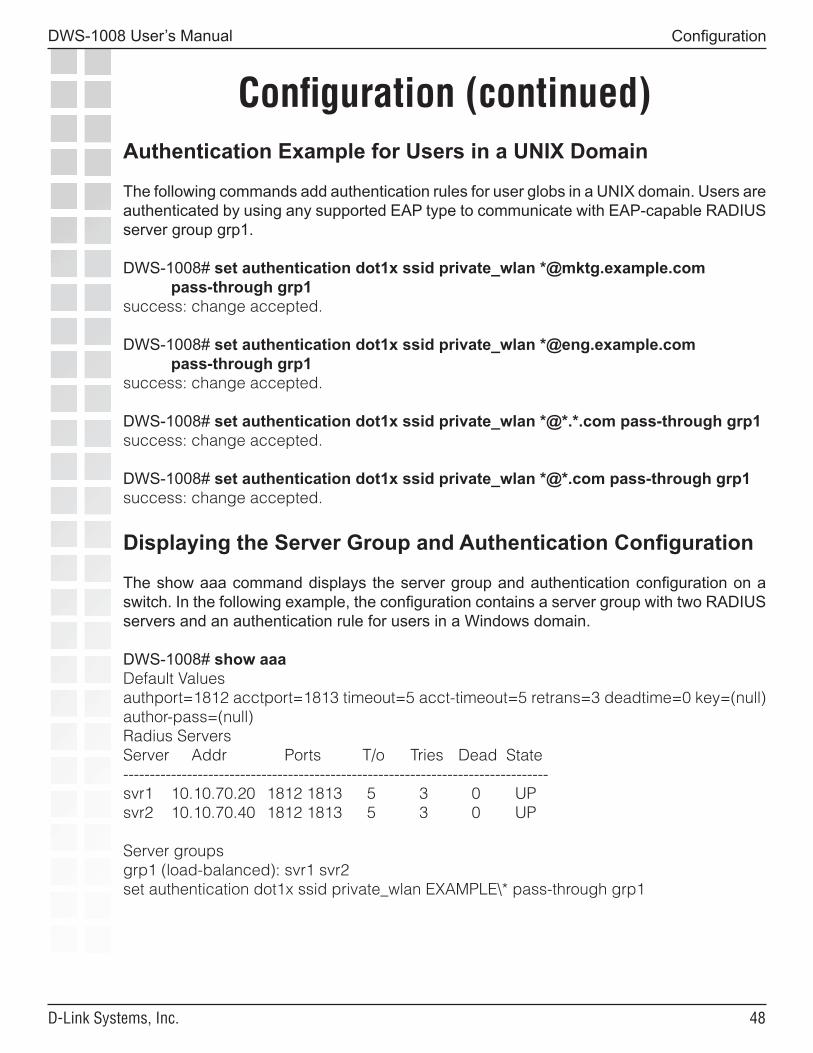
��
DWS-1008 User’s Manual
D-Link Systems, Inc.
Configuration (continued)
Configuration
Authentication Example for Users in a UNIX Domain
The following commands add authentication rules for user globs in a UNIX domain. Users are authenticated by using any supported EAP type to communicate with EAP-capable RADIUS server group grp1.
DWS-1008# set authentication dot1x ssid private_wlan *@mktg.example.com pass-through grp1success: change accepted.
DWS-1008# set authentication dot1x ssid private_wlan *@eng.example.com pass-through grp1success: change accepted.
DWS-1008# set authentication dot1x ssid private_wlan *@*.*.com pass-through grp1success: change accepted.
DWS-1008# set authentication dot1x ssid private_wlan *@*.com pass-through grp1success: change accepted.
Displaying the Server Group and Authentication Configuration
The show aaa command displays the server group and authentication configuration on a switch. In the following example, the configuration contains a server group with two RADIUS servers and an authentication rule for users in a Windows domain.
DWS-1008# show aaaDefault Valuesauthport=1812 acctport=1813 timeout=5 acct-timeout=5 retrans=3 deadtime=0 key=(null) author-pass=(null)Radius ServersServer Addr Ports T/o Tries Dead State--------------------------------------------------------------------------------svr1 10.10.70.20 1812 1813 5 3 0 UPsvr2 10.10.70.40 1812 1813 5 3 0 UP
Server groupsgrp1 (load-balanced): svr1 svr2set authentication dot1x ssid private_wlan EXAMPLE\* pass-through grp1
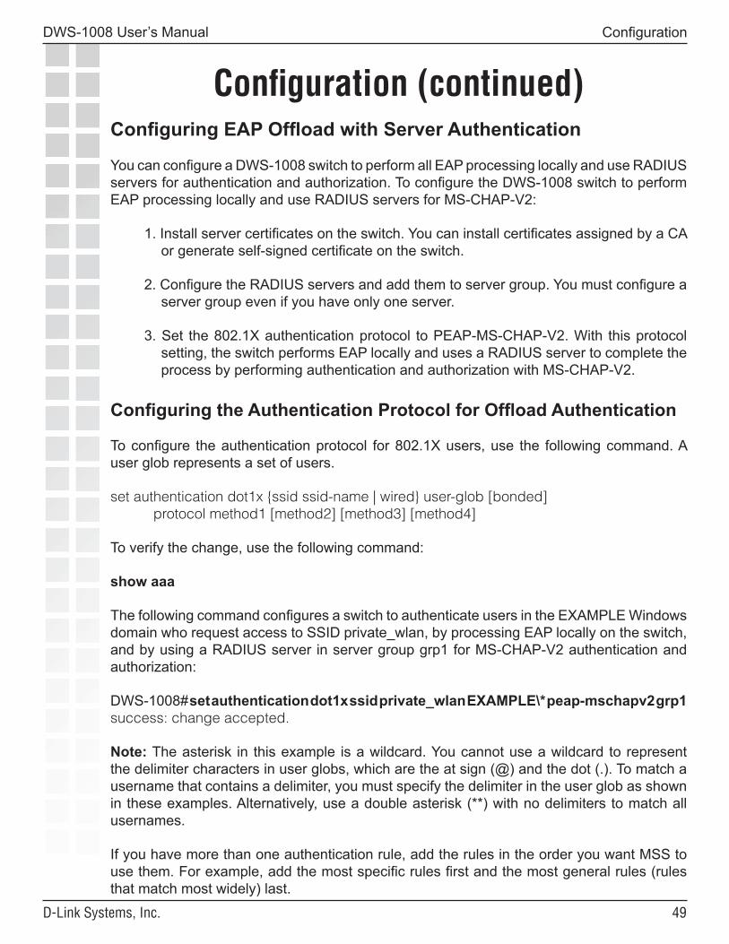
��
DWS-1008 User’s Manual
D-Link Systems, Inc.
Configuration (continued)
Configuration
Configuring EAP Offload with Server Authentication
You can configure a DWS-1008 switch to perform all EAP processing locally and use RADIUS servers for authentication and authorization. To configure the DWS-1008 switch to perform EAP processing locally and use RADIUS servers for MS-CHAP-V2:
1. Install server certificates on the switch. You can install certificates assigned by a CA or generate self-signed certificate on the switch.
2. Configure the RADIUS servers and add them to server group. You must configure a server group even if you have only one server.
3. Set the 802.1X authentication protocol to PEAP-MS-CHAP-V2. With this protocol setting, the switch performs EAP locally and uses a RADIUS server to complete the process by performing authentication and authorization with MS-CHAP-V2.
Configuring the Authentication Protocol for Offload Authentication
To configure the authentication protocol for 802.1X users, use the following command. A user glob represents a set of users.
set authentication dot1x {ssid ssid-name | wired} user-glob [bonded] protocol method1 [method2] [method3] [method4]
To verify the change, use the following command:
show aaa
The following command configures a switch to authenticate users in the EXAMPLE Windows domain who request access to SSID private_wlan, by processing EAP locally on the switch, and by using a RADIUS server in server group grp1 for MS-CHAP-V2 authentication and authorization:
DWS-1008# set authentication dot1x ssid private_wlan EXAMPLE\* peap-mschapv2 grp1 success: change accepted.
Note: The asterisk in this example is a wildcard. You cannot use a wildcard to represent the delimiter characters in user globs, which are the at sign (@) and the dot (.). To match a username that contains a delimiter, you must specify the delimiter in the user glob as shown in these examples. Alternatively, use a double asterisk (**) with no delimiters to match all usernames.
If you have more than one authentication rule, add the rules in the order you want MSS to use them. For example, add the most specific rules first and the most general rules (rules that match most widely) last.
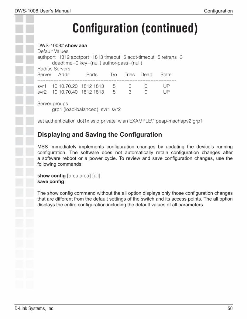
�0
DWS-1008 User’s Manual
D-Link Systems, Inc.
Configuration (continued)
Configuration
DWS-1008# show aaaDefault Valuesauthport=1812 acctport=1813 timeout=5 acct-timeout=5 retrans=3 deadtime=0 key=(null) author-pass=(null)Radius ServersServer Addr Ports T/o Tries Dead State--------------------------------------------------------------------------------------svr1 10.10.70.20 1812 1813 5 3 0 UPsvr2 10.10.70.40 1812 1813 5 3 0 UP
Server groups grp1 (load-balanced): svr1 svr2
set authentication dot1x ssid private_wlan EXAMPLE\* peap-mschapv2 grp1
Displaying and Saving the Configuration
MSS immediately implements configuration changes by updating the device’s running configuration. The software does not automatically retain configuration changes after a software reboot or a power cycle. To review and save configuration changes, use the following commands:
show config [area area] [all]save config
The show config command without the all option displays only those configuration changes that are different from the default settings of the switch and its access points. The all option displays the entire configuration including the default values of all parameters.
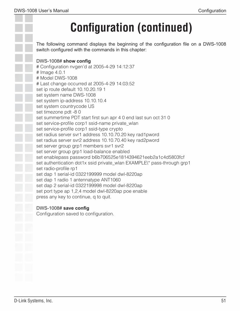
��
DWS-1008 User’s Manual
D-Link Systems, Inc.
Configuration (continued)
Configuration
The following command displays the beginning of the configuration file on a DWS-1008 switch configured with the commands in this chapter:
DWS-1008# show config# Configuration nvgen’d at 2005-4-29 14:12:37# Image 4.0.1# Model DWS-1008# Last change occurred at 2005-4-29 14:03:52set ip route default 10.10.20.19 1set system name DWS-1008set system ip-address 10.10.10.4set system countrycode USset timezone pdt -8 0set summertime PDT start first sun apr 4 0 end last sun oct 31 0set service-profile corp1 ssid-name private_wlanset service-profile corp1 ssid-type cryptoset radius server svr1 address 10.10.70.20 key rad1pwordset radius server svr2 address 10.10.70.40 key rad2pwordset server group grp1 members svr1 svr2set server group grp1 load-balance enabledset enablepass password b6b706525e1814394621eeb2a1c4d5803fcfset authentication dot1x ssid private_wlan EXAMPLE\* pass-through grp1set radio-profile rp1set dap 1 serial-id 0322199999 model dwl-8220apset dap 1 radio 1 antennatype ANT1060set dap 2 serial-id 0322199998 model dwl-8220apset port type ap 1,2,4 model dwl-8220ap poe enablepress any key to continue, q to quit.
DWS-1008# save configConfiguration saved to configuration.
��
DWS-1008 User’s Manual
D-Link Systems, Inc.
Configuring AAA for Administrative and Local Access
Overview of AAA for Administrative and Local Access
D-Link Mobility System Software (MSS) supports authentication, authorization, and accounting (AAA) for secure network connections. As administrator, you must establish administrative access for yourself and optionally other local users before you can configure the DWS-1008 for operation.
Here is an overview of configuration topics:
• Console connection. By default, any administrator can connect to the console port and manage the switch, because no authentication is enforced. (D-Link recommends that you enforce authentication on the console port after initial connection.)
• Telnet or SSH connection. Administrators cannot establish a Telnet or Secure Shell (SSH) connection to the DWS-1008 by default. To provide Telnet or SSH access, you must add a username and password entry to the local database or, optionally, set the authentication method for Telnet users to a Remote Authentication Dial-In User Service (RADIUS) server.
• Restricted mode. When you initially connect to the DWS-1008, your mode of operation is restricted. In this mode, only a small subset of status and monitoring commands is available. Restricted mode is useful for administrators with basic monitoring privileges who are not allowed to change the configuration or run traces.
• Enabled mode. To enter the enabled mode of operation, you type the enable command at the command prompt. In enabled mode, you can use all CLI commands. Although MSS does not require an enable password, D-Link highly recommends that you set one.
• Customized authentication. You can require authentication for all users or for only a subset of users. Username globbing allows different users or classes of user to be given different authentication treatments. You can configure console authentication and Telnet authentication separately, and you can apply different authentication methods to each. For any user, authorization uses the same method(s) as authentication for that user.
• Local override. A special authentication technique called local override lets you attempt authentication via the local database before attempting authentication via a RADIUS server. The switch attempts administrative authentication in the local database first. If it finds no match, the DWS-1008 attempts administrative authentication on the RADIUS server.Note. A CLI Telnet connection to the DWS-1008 is not secure, unlike SSH connections.
Configuring AAA for Administrative and Local Access
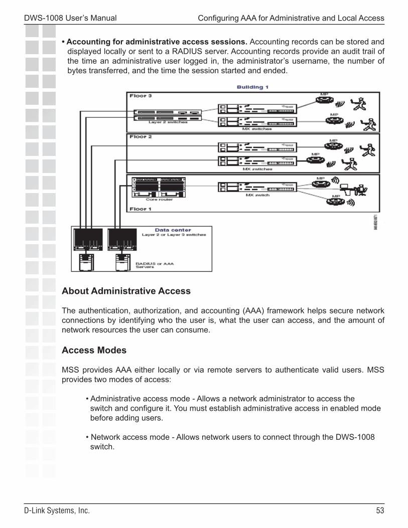
��
DWS-1008 User’s Manual
D-Link Systems, Inc.
Configuring AAA for Administrative and Local Access
• Accounting for administrative access sessions. Accounting records can be stored and displayed locally or sent to a RADIUS server. Accounting records provide an audit trail of the time an administrative user logged in, the administrator’s username, the number of bytes transferred, and the time the session started and ended.
The figure below illustrates a typical switch, DWL-8220AP access points, and network administrator in an enterprise network. As network administrator, you initially access the DWS-1008 switch via the console. You can then optionally configure authentication, authorization, and accounting for administrative access mode. D-Link recommends enforcing authentication for administrative access using usernames and passwords stored either locally or on RADIUS servers.
About Administrative Access
The authentication, authorization, and accounting (AAA) framework helps secure network connections by identifying who the user is, what the user can access, and the amount of network resources the user can consume.
Access Modes
MSS provides AAA either locally or via remote servers to authenticate valid users. MSS provides two modes of access:
• Administrative access mode - Allows a network administrator to access the switch and configure it. You must establish administrative access in enabled mode before adding users.
• Network access mode - Allows network users to connect through the DWS-1008 switch.
��
DWS-1008 User’s Manual
D-Link Systems, Inc.
Configuring AAA for Administrative and Local Access
Types of Administrative Access
MSS allows you access to the switch with the following types of administrative access:
• Console - Access via only the console port. • Telnet - Users who access MSS via the Telnet protocol. • Secure Shell (SSH) - Users who access MSS via the SSH protocol.
First-Time Configuration via the Console
Administrators must initially configure the DWS-1008 switch with a computer or terminal connected to the DWS-1008 console port through a serial cable. Telnet access is not initially enabled.To configure a previously unconfigured DWS-1008 switch via the console, you must complete the following tasks:
• Enable an administrator. • Configure authentication. • Optionally, configure accounting. • Save the configuration.
Enabling an Administrator
To enable yourself as an administrator, you must log in to the DWS-1008 switch from the console. Until you set the enable password and configure authentication, the default username and password are blank. Press Enter when prompted for them. To enable an administrator:
1. Log in to the DWS-1008 switch from the serial console, and press Enter when the switch displays a username prompt:
Username:
2. Press Enter when the DWS-1008 switch displays a password prompt.
Password:
3. Type enable to go into enabled mode.
DWS-1008> enable
4. Press Enter to display an enabled-mode command prompt:
DWS-1008#
Once you see this prompt after you have typed the enable command, you have administrative privileges, which allow you to further configure the DWS-1008 switch.
��
DWS-1008 User’s Manual
D-Link Systems, Inc.
Configuring AAA for Administrative and Local Access
Setting the DWS-1008 Switch Enable Password
There is one enable password for the entire DWS-1008 switch. You can optionally change the enable password from the default.
Setting the DWS-1008 Enable Password for the First Time
To set the enable password for the first time:1. At the enabled prompt, type set enablepass.
2. At the “Enter old password” prompt, press Enter.
3. At the “Enter new password” prompt, enter an enable password of up to 32 alphanumeric characters with no spaces. The password is not displayed as you type it.
4. Type the password again to confirm it.
MSS lets you know the password is set.
DWS-1008# set enablepassEnter old password:Enter new password:Retype new password:Password changed
Caution: D-Link recommends that you change the enable password from the default (no password) to prevent unauthorized users from entering configuration commands. The enable password is case-sensitive.
Be sure to use a password that you will remember. If you lose the enable password, the only way to restore it causes the system to return to its default settings and wipes out any saved configuration.
5. Store the configuration into nonvolatile memory by typing the following command:
DWS-1008# save configsuccess: configuration saved.
Authenticating at the Console
You can configure the console so that authentication is required, or so that no authentication is required. D-Link recommends that you enforce authentication on the console port.To enforce console authentication, take the following steps:
1. Add a user in the local database by typing the following command with a username and password:
DWS-1008# set user username password passwordsuccess: change accepted.
��
DWS-1008 User’s Manual
D-Link Systems, Inc.
Configuring AAA for Administrative and Local Access
2. To enforce the use of console authentication via the local database, type the following command:
DWS-1008# set authentication console * local
Caution: If you type this command before you have created a local username and password, you can lock yourself out of the DWS-1008 switch. Before entering this command, you must configure a local username and password.
3 To store this configuration into nonvolatile memory, type the following command:
DWS-1008# save configsuccess: configuration saved.
By default, no authentication is required at the console. If you have previously required authentication and have decided not to require it (during testing, for example), type the following command to configure the console so that it does not require username and password authentication:
DWS-1008# set authentication console * none
Customizing AAA with “Globs” and Groups
“Globbing” lets you classify users by username or media access control (MAC) address for different AAA treatments. A user glob is a string, possibly containing wildcards, for matching AAA and IEEE 802.1X authentication methods to a user or set of users. The switch supports the following wildcard characters for user globs:
• Single asterisk (*) matches the characters in a username up to but not including a separator character, which can be an at (@) sign or a period (.).
• Double asterisk (**) matches all usernames.
In a similar fashion, MAC address globs match authentication methods to a MAC address or set of MAC addresses.
Note. The authentication method none you can specify for administrative access is different from the fallthru authentication type None, which applies only to network access. The authentication method none allows access to the switch by an administrator. The fallthru authentication type None denies access to a network user.
A user group is a named collection of users or MAC addresses sharing a common authorization policy. For example, you might group all users on the first floor of building 17 into the group bldg-17-1st-floor, or group all users in the IT group into the group infotech-people. Individual user entries override group entries if they both configure the same attribute.
��
DWS-1008 User’s Manual
D-Link Systems, Inc.
Configuring AAA for Administrative and Local Access
Setting User Passwords
Like usernames, passwords are case-sensitive. To make passwords secure, make sure they contain uppercase and lowercase letters and numbers. D-Link recommends that all users create passwords that are memorable to themselves, difficult for others to guess, and not subject to a dictionary attack. User passwords are automatically encrypted when entered in the local database. However, the encryption is not strong. It is designed only to discourage someone looking over your shoulder from memorizing your password as you display the configuration. To maintain security, MSS displays only the encrypted form of the password in show commands.
Adding and Clearing Local Users for Administrative Access
Usernames and passwords can be stored locally on the DWS-1008 switch. D-Link recommends that you enforce console authentication after the initial configuration to prevent anyone with unauthorized access to the console from logging in. The local database on the DWS-1008 switch is the simplest way to store user information in a D-Link system. To configure a user in the local database, type the following command:
set user username password password
Note. Although MSS allows you to configure a user password for the special “last-resort” guest user, the password has no effect. Last-resort users can never access a DWS-1008 in administrative mode and never require a password.
For example, to configure user Jose with the password spRin9 in the local database on the DWS-1008 switch, type the following command:
DWS-1008# set user Jose password spRin9success: User Jose created
To clear a user from the local database, type the following command:
clear user username
Configuring Accounting for Administrative Users
Accounting allows you to track network resources. Accounting records can be updated for three important events: when the user is first connected, when the user roams from one DWL-8220AP access point to another, and when the user terminates his or her session. The default for accounting is off.
To configure accounting for administrative logins, use the following command:
set accounting {admin | console} {user-glob} {start-stop | stop-only}method1 [method2] [method3] [method4]
��
DWS-1008 User’s Manual
D-Link Systems, Inc.
Configuring AAA for Administrative and Local Access
To configure accounting for administrative logins over the network at EXAMPLE, enter the following command:
set accounting admin EXAMPLE\* start-stop | stop-only aaa-method
You can select either start-stop or stop-only accounting modes. The stop-only mode sends only stop records, whereas start-stop sends both start and stop records, effectively doubling the number of accounting records. In most cases, stop-only is entirely adequate for administrative accounting, because a stop record contains all the information you might need about a session.In the set accounting command, you must include AAA methods that specify whether to use the local database or RADIUS server to receive the accounting records. Specify local, which causes the processing to be done on the DWS-1008 switch, or specify a RADIUS server group.
For example, you can set accounting for administrative users using the start-stop mode via the local database:
DWS-1008# set accounting admin EXAMPLE\* start-stop localsuccess: change accepted.
The accounting records show the date and time of activity, the user’s status and name, and other attributes. The show accounting statistics command displays accounting records for administrative users after they have logged in to the DWS-1008 switch.
For example, the following accounting records show information about user Geetha’s sessions:
DWS-1008# show accounting statisticsSep 26 11:01:48 Acct-Status-Type=START Acct-Authentic=0 User-Name=GeethaAAA_TTY_ATTR=2 Event-Timestamp=1064599308Sept 26 12:50:21 Acct-Status-Type=STOP Acct-Authentic=0 User-Name=GeethaAAA_TTY_ATTR=2 Acct-Session-Time=6513 Event-Timestamp=1064605821Acct-Output-Octets=332 Acct-Input-Octets=61Sep 26 12:50:33 Acct-Status-Type=START Acct-Authentic=0 User-Name=GeethaAAA_TTY_ATTR=2 Event-Timestamp=1064605833
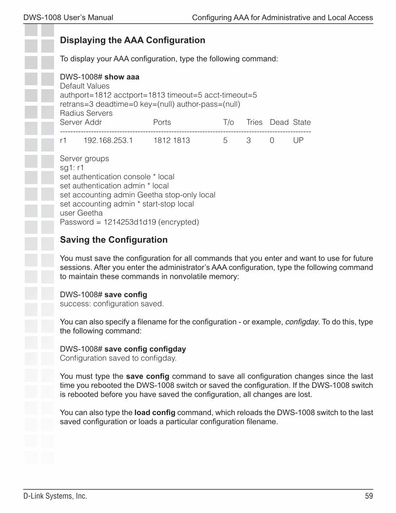
��
DWS-1008 User’s Manual
D-Link Systems, Inc.
Configuring AAA for Administrative and Local Access
Displaying the AAA Configuration
To display your AAA configuration, type the following command:
DWS-1008# show aaaDefault Valuesauthport=1812 acctport=1813 timeout=5 acct-timeout=5retrans=3 deadtime=0 key=(null) author-pass=(null)Radius ServersServer Addr Ports T/o Tries Dead State-------------------------------------------------------------------------------------------------r1 192.168.253.1 1812 1813 5 3 0 UP
Server groupssg1: r1set authentication console * localset authentication admin * localset accounting admin Geetha stop-only localset accounting admin * start-stop localuser GeethaPassword = 1214253d1d19 (encrypted)
Saving the Configuration
You must save the configuration for all commands that you enter and want to use for future sessions. After you enter the administrator’s AAA configuration, type the following command to maintain these commands in nonvolatile memory:
DWS-1008# save configsuccess: configuration saved.
You can also specify a filename for the configuration - or example, configday. To do this, type the following command:
DWS-1008# save config configdayConfiguration saved to configday.
You must type the save config command to save all configuration changes since the last time you rebooted the DWS-1008 switch or saved the configuration. If the DWS-1008 switch is rebooted before you have saved the configuration, all changes are lost.
You can also type the load config command, which reloads the DWS-1008 switch to the last saved configuration or loads a particular configuration filename.
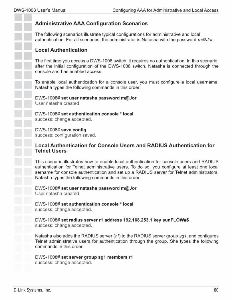
�0
DWS-1008 User’s Manual
D-Link Systems, Inc.
Configuring AAA for Administrative and Local Access
Administrative AAA Configuration Scenarios
The following scenarios illustrate typical configurations for administrative and local authentication. For all scenarios, the administrator is Natasha with the password m@Jor.
Local Authentication
The first time you access a DWS-1008 switch, it requires no authentication. In this scenario, after the initial configuration of the DWS-1008 switch, Natasha is connected through the console and has enabled access.
To enable local authentication for a console user, you must configure a local username. Natasha types the following commands in this order:
DWS-1008# set user natasha password m@JorUser natasha created
DWS-1008# set authentication console * localsuccess: change accepted.
DWS-1008# save configsuccess: configuration saved.
Local Authentication for Console Users and RADIUS Authentication for Telnet Users
This scenario illustrates how to enable local authentication for console users and RADIUS authentication for Telnet administrative users. To do so, you configure at least one local sername for console authentication and set up a RADIUS server for Telnet administrators. Natasha types the following commands in this order:
DWS-1008# set user natasha password m@JorUser natasha created
DWS-1008# set authentication console * localsuccess: change accepted.
DWS-1008# set radius server r1 address 192.168.253.1 key sunFLOW#$success: change accepted.
Natasha also adds the RADIUS server (r1) to the RADIUS server group sg1, and configures Telnet administrative users for authentication through the group. She types the following commands in this order:
DWS-1008# set server group sg1 members r1success: change accepted.
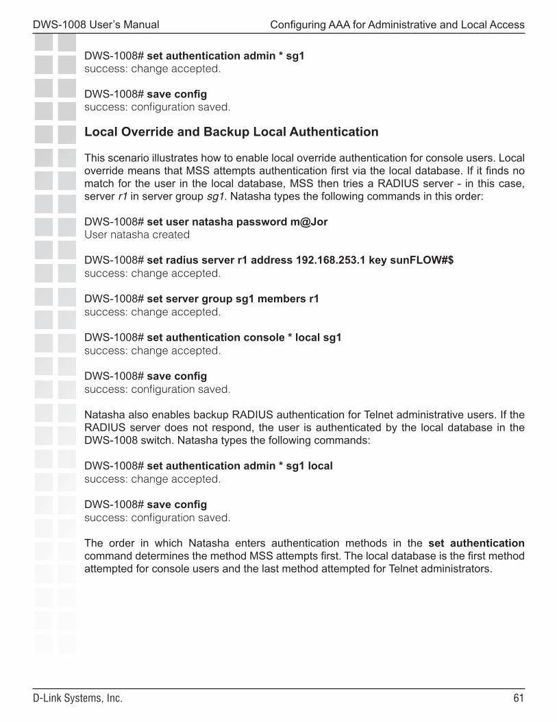
��
DWS-1008 User’s Manual
D-Link Systems, Inc.
Configuring AAA for Administrative and Local Access
DWS-1008# set authentication admin * sg1success: change accepted.
DWS-1008# save configsuccess: configuration saved.
Local Override and Backup Local Authentication
This scenario illustrates how to enable local override authentication for console users. Local override means that MSS attempts authentication first via the local database. If it finds no match for the user in the local database, MSS then tries a RADIUS server - in this case, server r1 in server group sg1. Natasha types the following commands in this order:
DWS-1008# set user natasha password m@JorUser natasha created
DWS-1008# set radius server r1 address 192.168.253.1 key sunFLOW#$success: change accepted.
DWS-1008# set server group sg1 members r1success: change accepted.
DWS-1008# set authentication console * local sg1success: change accepted.
DWS-1008# save configsuccess: configuration saved.
Natasha also enables backup RADIUS authentication for Telnet administrative users. If the RADIUS server does not respond, the user is authenticated by the local database in the DWS-1008 switch. Natasha types the following commands:
DWS-1008# set authentication admin * sg1 localsuccess: change accepted.
DWS-1008# save configsuccess: configuration saved.
The order in which Natasha enters authentication methods in the set authentication command determines the method MSS attempts first. The local database is the first method attempted for console users and the last method attempted for Telnet administrators.
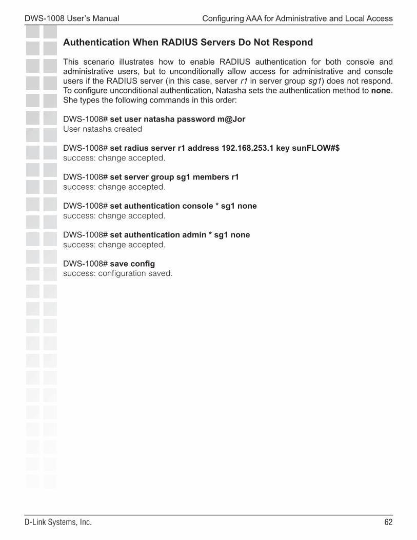
��
DWS-1008 User’s Manual
D-Link Systems, Inc.
Configuring AAA for Administrative and Local Access
Authentication When RADIUS Servers Do Not Respond
This scenario illustrates how to enable RADIUS authentication for both console and administrative users, but to unconditionally allow access for administrative and console users if the RADIUS server (in this case, server r1 in server group sg1) does not respond. To configure unconditional authentication, Natasha sets the authentication method to none. She types the following commands in this order:
DWS-1008# set user natasha password m@JorUser natasha created
DWS-1008# set radius server r1 address 192.168.253.1 key sunFLOW#$success: change accepted.
DWS-1008# set server group sg1 members r1success: change accepted.
DWS-1008# set authentication console * sg1 nonesuccess: change accepted.
DWS-1008# set authentication admin * sg1 nonesuccess: change accepted.
DWS-1008# save configsuccess: configuration saved.
��
DWS-1008 User’s Manual
D-Link Systems, Inc.
Configuring and Managing Ports and VLANs
Configuring and ManagingPorts and VLANs
You can configure and display information for the following port parameters: • Port type • Name • Speed and autonegotiation • Port state • Power over Ethernet (PoE) state • Load sharing
Setting the Port Type
A switch port can be one of the following types:
• Network port. A network port is a Layer 2 switch port that connects the switch to other networking devices such as switches and routers. • AP access port. An AP access port connects the switch to a DWL-8220AP access point. The port also can provide power to the access point. Wireless users are authenticated to the network through an AP access port. • Wired authentication port. A wired authentication port connects the switch to user devices, such as workstations, that must be authenticated to access the network.
All DWS-1008 switch ports are network ports by default. You must set the port type for ports directly connected to AP access ports and to wired user stations that must be authenticated to access the network. When you change port type, MSS applies default settings appropriate for the port type. Table 1 lists the default settings applied for each port type. For example, the access point column lists default settings that MSS applies when you change a port type to ap.
Note. A Distributed AP, which is connected to DWS-1008 switches through intermediate Layer 2 or Layer 3 networks, does not use an AP access port.
Setting a Port for a Directly Connected DWL-8220AP Access Point
To set a port for a DWL-8220AP access point, use the following command:
set port type ap port-list
model {DWL-8220AP} poe {enable | disable} [radiotype {11a | 11b| 11g}]
You must specify a port list of one or more port numbers, the model number, and the PoE state.
Note. Before configuring a port as an access port, you must use the set system countrycode command to set the IEEE 802.11 country-specific regulations on the switch.
��
DWS-1008 User’s Manual
D-Link Systems, Inc.
Configuring and Managing Ports and VLANs
To set ports 4 through 6 for the DWL-8220AP and enable PoE on the ports, type the following command:
DWS-1008# set port type ap 4-6 model DWL-8220AP poe enableThis may affect the power applied on the configured ports. Would you liketo continue? (y/n) [n]ysuccess: change accepted.
DWS-1008# set port type ap 2 model DWL-8220AP poe enable radiotype 11bThis may affect the power applied on the configured ports. Would you liketo continue? (y/n) [n]ysuccess: change accepted.
Configuring for a Distributed AP
To configure a connection for a Distributed AP (referred to as a DAP in the CLI),use the following command:
set dap dap-num serial-id serial-IDmodel {DWL-8220AP} [radiotype {11a | 11b| 11g}]
The dap-num parameter identifies the Distributed AP connection for the DWL-8220AP. Therange of valid connection ID numbers is 1 to 30.
For the serial-id parameter, specify the serial ID of the AP. The serial ID is listed on the case. To display the serial ID using the CLI, use the show version details command.
The model and radiotype parameters have the same options as they do with the set port type ap command. Because the switch does not supply power to an indirectly connected AP, the set dap command does not use the poe parameter.
To configure Distributed AP connection 1 for the DWL-8220AP with serial-ID0322199999, type the following command:
DWS-1008# set dap 1 serial-id 0322199999 model DWL-8220APsuccess: change accepted.
To configure Distributed AP connection 2 with serial-ID 0322188888 and radio type 802.11a, type the following command:
DWS-1008# set dap 2 serial-id 0322188888 model dwl-8220ap radiotype 11asuccess: change accepted.
��
DWS-1008 User’s Manual
D-Link Systems, Inc.
Configuring and Managing Ports and VLANs
Setting a Port for a Wired Authentication User
To set a port for a wired authentication user, use the following command:
set port type wired-auth port-list [tag tag-list] [max-sessions num][auth-fall-thru {last-resort | none}]
You must specify a port list. Optionally, you also can specify a tag-list to subdivide the port into virtual ports, set the maximum number of simultaneous user sessions that can be active on the port, and change the fallthru authentication method.
By default, one user session can be active on the port at a time. The fallthru authentication type is used if the user does not support 802.1X and is not authenticated by MAC authentication. The default is none, which means the user is automatically denied access if neither 802.1X authentication or MAC authentication is successful.
To set port 2 as a wired authentication port, type the following command:
DWS-1008# set port type wired-auth 2success: change accepted
This command configures port 2 as a wired authentication port supporting one interface and one simultaneous user session.
Clearing a Port
To change a port’s type from AP access port or wired authentication port, you must first clear the port, then set the port type. Clearing a port removes all the port’s configuration settings and resets the port as a network port.
• If the port is an AP access port, clearing the port disables PoE and 802.1X authentication. • If the port is a wired authenticated port, clearing the port disables 802.1X authentication. • If the port is a network port, the port must first be removed from all VLANs, which removes the port from all spanning trees, load-sharing port groups, and so on.
To clear a port, use the following command:
clear port type port-list
��
DWS-1008 User’s Manual
D-Link Systems, Inc.
Configuring and Managing Ports and VLANs
Clearing a Port (continued)
Note: If clients are connected to a wired authentication port through a downstream third-party switch, the switch attempts to authenticate based on any traffic coming from the switch, such as Spanning Tree Protocol (STP) BPDUs. In this case, disable repetitive traffic emissions such as STP BPDUs from downstream switches. If you want to provide a management path to a downstream switch, use MAC authentication.
Caution: When you clear a port, MSS ends user sessions that are using the port. A cleared port is not placed in any VLANs, not even the default VLAN (VLAN 1).
For example, to clear the port-related settings from port 5 and reset the port as a network port, type the following command:
DWS-1008# clear port type 5This may disrupt currently authenticated users. Are you sure? (y/n) [n]ysuccess: change accepted.
Clearing a Distributed AP
To clear a Distributed AP, use the following command:
clear dap dap-num
Configuring a Port Name
Each switch port has a number but does not have a name by default. To set a port name, use the following command:
set port port name name
You can specify only a single port number with the command. To set the name of port 3 to adminpool, type the following command:
DWS-1008# set port 3 name adminpoolsuccess: change accepted.
Caution: When you clear a Distributed AP, MSS ends user sessions that are using the AP.
Note. To avoid confusion, D-Link recommends that you do not use numbers as port names.
Removing a Port Name
To remove a port name, use the following command:
clear port port-list name
��
DWS-1008 User’s Manual
D-Link Systems, Inc.
Configuring and Managing Ports and VLANs
Configuring Port Operating Parameters
Autonegotiation is enabled by default on a switch’s 10/100 Ethernet ports.You can configure the following port operating parameters:
• Speed • Autonegotiation • Port state • PoE state
You also can toggle a port’s administrative state and PoE setting off and back on to reset the port.
10/100 Ports—Autonegotiation and Port Speed
10/100 Ethernet ports use autonegotiation by default to determine the appropriate port speed. Ports on the DWS-1008 switch support half-duplex and full-duplex operation.
To explicitly set the port speed of a 10/100 port, use the following command:
set port speed port-list {10 | 100 | auto}
To set the port speed on ports 1, 3 through 6 to 10 Mbps, type the following command:
DWS-1008# set port speed 1,3-6 10
Disabling or Reenabling a Port
All ports are enabled by default. To administratively disable a port, use the following command:
set port {enable | disable} port-list
A port that is administratively disabled cannot send or receive packets. This command does not affect the link state of the port.
Disabling or Reenabling Power over Ethernet
Power over Ethernet (PoE) supplies DC power to a device connected to a DWL-8220AP access port. The PoE state depends on whether you enable or disable PoE when you set the port type.
Caution: Use the DWS-1008 switch’s PoE only to power D-Link DWL-8220AP access points. If you enable PoE on ports connected to other devices, damage can result.
To change the PoE state on a port, use the following command:
set port poe port-list enable | disable
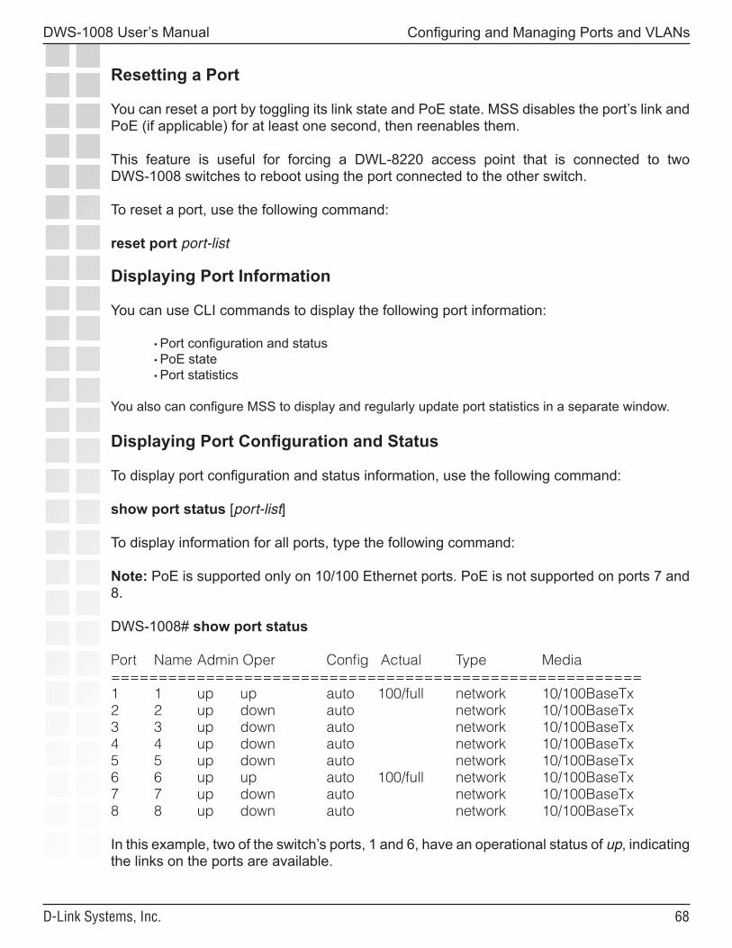
��
DWS-1008 User’s Manual
D-Link Systems, Inc.
Configuring and Managing Ports and VLANs
Resetting a Port
You can reset a port by toggling its link state and PoE state. MSS disables the port’s link and PoE (if applicable) for at least one second, then reenables them.
This feature is useful for forcing a DWL-8220 access point that is connected to two DWS-1008 switches to reboot using the port connected to the other switch.
To reset a port, use the following command:
reset port port-list
Displaying Port Information
You can use CLI commands to display the following port information:
• Port configuration and status • PoE state • Port statistics
You also can configure MSS to display and regularly update port statistics in a separate window.
Displaying Port Configuration and Status
To display port configuration and status information, use the following command:
show port status [port-list]
To display information for all ports, type the following command:
Note: PoE is supported only on 10/100 Ethernet ports. PoE is not supported on ports 7 and 8.
DWS-1008# show port status
Port Name Admin Oper Config Actual Type Media========================================================1 1 up up auto 100/full network 10/100BaseTx2 2 up down auto network 10/100BaseTx3 3 up down auto network 10/100BaseTx4 4 up down auto network 10/100BaseTx5 5 up down auto network 10/100BaseTx6 6 up up auto 100/full network 10/100BaseTx7 7 up down auto network 10/100BaseTx8 8 up down auto network 10/100BaseTx
In this example, two of the switch’s ports, 1 and 6, have an operational status of up, indicating the links on the ports are available.
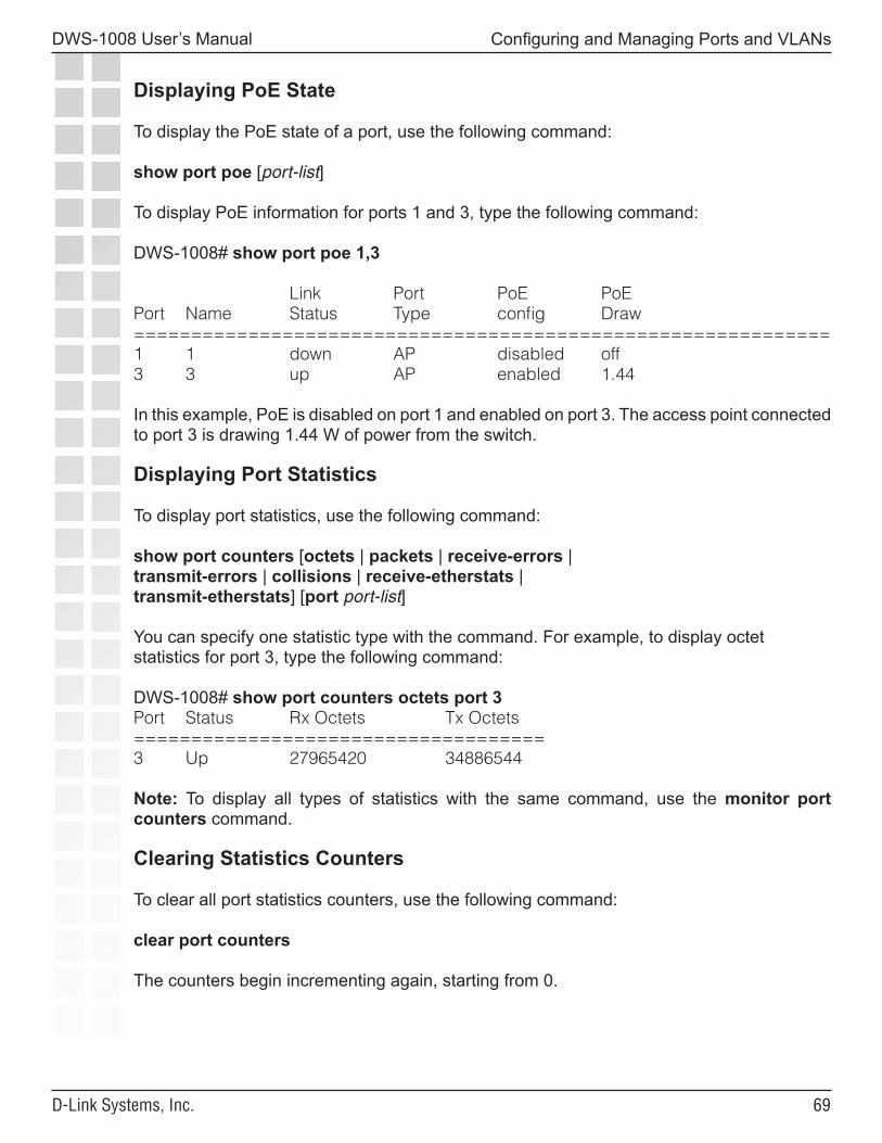
��
DWS-1008 User’s Manual
D-Link Systems, Inc.
Configuring and Managing Ports and VLANs
Displaying PoE State
To display the PoE state of a port, use the following command:
show port poe [port-list]
To display PoE information for ports 1 and 3, type the following command:
DWS-1008# show port poe 1,3
Link Port PoE PoEPort Name Status Type config Draw=============================================================1 1 down AP disabled off3 3 up AP enabled 1.44
In this example, PoE is disabled on port 1 and enabled on port 3. The access point connected to port 3 is drawing 1.44 W of power from the switch.
Displaying Port Statistics
To display port statistics, use the following command:
show port counters [octets | packets | receive-errors |transmit-errors | collisions | receive-etherstats |transmit-etherstats] [port port-list]
You can specify one statistic type with the command. For example, to display octet statistics for port 3, type the following command:
DWS-1008# show port counters octets port 3Port Status Rx Octets Tx Octets====================================3 Up 27965420 34886544
Note: To display all types of statistics with the same command, use the monitor port counters command.
Clearing Statistics Counters
To clear all port statistics counters, use the following command:
clear port counters
The counters begin incrementing again, starting from 0.
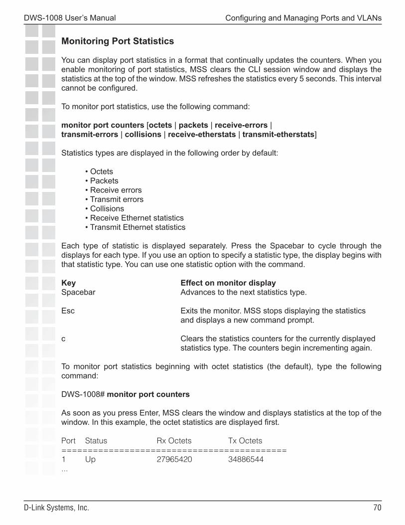
�0
DWS-1008 User’s Manual
D-Link Systems, Inc.
Configuring and Managing Ports and VLANs
Monitoring Port Statistics
You can display port statistics in a format that continually updates the counters. When you enable monitoring of port statistics, MSS clears the CLI session window and displays the statistics at the top of the window. MSS refreshes the statistics every 5 seconds. This interval cannot be configured.
To monitor port statistics, use the following command:
monitor port counters [octets | packets | receive-errors |transmit-errors | collisions | receive-etherstats | transmit-etherstats]
Statistics types are displayed in the following order by default:
• Octets • Packets • Receive errors • Transmit errors • Collisions • Receive Ethernet statistics • Transmit Ethernet statistics
Each type of statistic is displayed separately. Press the Spacebar to cycle through the displays for each type. If you use an option to specify a statistic type, the display begins with that statistic type. You can use one statistic option with the command.
Key Effect on monitor displaySpacebar Advances to the next statistics type.
Esc Exits the monitor. MSS stops displaying the statistics and displays a new command prompt.
c Clears the statistics counters for the currently displayed statistics type. The counters begin incrementing again.
To monitor port statistics beginning with octet statistics (the default), type the following command:
DWS-1008# monitor port counters
As soon as you press Enter, MSS clears the window and displays statistics at the top of the window. In this example, the octet statistics are displayed first.
Port Status Rx Octets Tx Octets===========================================1 Up 27965420 34886544...
��
DWS-1008 User’s Manual
D-Link Systems, Inc.
Configuring and Managing Ports and VLANs
To cycle the display to the next set of statistics, press the Spacebar. In this example, packet statistics are displayed next:
Port Status Rx Unicast Rx NonUnicast Tx Unicast Tx NonUnicast=============================================================1 Up 54620 62144 68318 62556...
Configuring Load-Sharing Port Groups
A port group is a set of physical ports that function together as a single link and provide load sharing and link redundancy. Only network ports can participate in a port group.
You can configure up to 8 ports in a port group, in any combination of ports. The port numbers do not need to be contiguous.
Load Sharing
A DWS-1008 switch balances the port group traffic among the group’s physical ports by assigning traffic flows to ports based on the traffic’s source and destination MAC addresses. The switch assigns a traffic flow to an individual port and uses the same port for all subsequent traffic for that flow.
Link Redundancy
A port group ensures link stability by providing redundant connections for the same link. If an individual port in a group fails, the switch reassigns traffic to the remaining ports. When the failed port starts operating again, the switch begins using it for new traffic flows. Traffic that belonged to the port before it failed continues to be assigned to other ports.
Configuring a Port Group
To configure a port group, use the following command:
set port-group name group-name port-list mode {on | off}
Enter a name for the group and the ports contained in the group. The mode parameter adds or removes ports for a group that is already configured.
To modify a group:
• Adding ports - Enter the ports you want to add, then enter mode on. • Removing ports - Enter the ports you want to remove, then enter mode off.
To configure a port group named server1 containing ports 1 through 5 and enable the link, type the following command:
DWS-1008# set port-group name server1 1-5 mode onsuccess: change accepted.
��
DWS-1008 User’s Manual
D-Link Systems, Inc.
Configuring and Managing Ports and VLANs
Configuring a Port Group (continued)
After you configure a port group, you can use the port group name with commands that change Layer 2 configuration parameters to apply configuration changes to all ports in the port group. For example, Spanning Tree Protocol (STP) and VLAN membership changes affect the entire port group instead of individual ports. When you make Layer 2 configuration changes, you can use a port group name in place of the port list. Ethernet port statistics continue to apply to individual ports, not to port groups.
To configure a port group named server2 containing ports 3 and 5 and add the ports to the default VLAN, type the following commands:
DWS-1008# set port-group name server2 3,5 mode onsuccess: change accepted.
DWS-1008# set vlan default port server2success: change accepted.
To verify the configuration change, type the following command:
DWS-1008# show vlan config Admin VLAN Tunl PortVLAN Name Status State Affin Port Tag State-----------------------------------------------------------------------------------------------------------1 default Up Up 5 server2 none Up
To indicate that the ports are configured as a port group, the show vlan config output lists the port group name instead of the individual port numbers.
Removing a Port Group
To remove a port group, use the following command:clear port-group name name
Displaying Port Group Information
To display port group information, use the following command:
show port-group [all | name group-name]
To display the configuration and status of port group server2, type the following command:
DWS-1008# show port-group name server2Port group: server2 is upPorts: 3, 5
��
DWS-1008 User’s Manual
D-Link Systems, Inc.
Configuring and Managing Ports and VLANs
Interoperating with Cisco Systems EtherChannel
Load-sharing port groups are interoperable with Cisco Systems EtherChannel capabilities. To configure a Cisco Catalyst switch to interoperate with a D-Link DWS-1008 switch, use the following command on the Catalyst switch:
set port channel port-list mode on
Configuring and Managing VLANs
Understanding VLANs
A virtual LAN (VLAN) is a Layer 2 broadcast domain that can span multiple wired or wireless LAN segments. Each VLAN is a separate logical network and, if you configure IP interfaces on the VLANs, MSS treats each VLAN as a separate IP subnet.
Note: The CLI commands in this chapter configure VLANs on network ports. The commands do not configure VLAN membership for wireless or wired authentication users. To assign a user to a VLAN, configure the RADIUS Tunnel-Private-Group-ID attribute or the VLAN-Name vendor specific attribute (VSA) for that user.
Only network ports can be preconfigured to be members of one or more VLAN(s). You configure VLANs on a switch’s network ports by configuring them on the switch itself. You configure a VLAN by assigning a name and network ports to the VLAN. Optionally, you can assign VLAN tag values on individual network ports. You can configure multiple VLANs on a switch’s network ports. Optionally, each VLAN can have an IP address.
VLANs are not configured on AP access ports or wired authentication ports, because the VLAN membership of these types of ports is determined dynamically through the authentication and authorization process. Users who require authentication connect through switch ports that are configured for access points or wired authentication access. Users are assigned to VLANs automatically through authentication and authorization mechanisms such as 802.1X.
By default, none of a switch’s ports are in VLANs. A switch cannot forward traffic on the network until you configure VLANs and add network ports to those VLANs.
VLANs, IP Subnets, and IP Addressing
Generally, VLANs are equivalent to IP subnets. If a switch is connected to the network by only one IP subnet, the switch must have at least one VLAN configured. Optionally, each VLAN can have its own IP address. However, no two IP addresses on the switch can belong to the same IP subnet.
You must assign the system IP address to one of the VLANs, for communications between switches and for unsolicited communications such as SNMP traps and RADIUS accounting messages. Any IP address configured on a switch can be used for management access unless explicitly restricted.
��
DWS-1008 User’s Manual
D-Link Systems, Inc.
Configuring and Managing Ports and VLANs
Note. A wireless client cannot join a VLAN if the physical network ports on the switch in the VLAN are down. However, a wireless client that is already in a VLAN whose physical network ports go down remains in the VLAN even though the VLAN is down.
Users and VLANs
When a user successfully authenticates to the network, the user is assigned to a specific VLAN. A user remains associated with the same VLAN throughout the user’s session on the network.
You assign a user to a VLAN by setting one of the following attributes on the RADIUS servers or in the local user database:
• Tunnel-Private-Group-ID - This attribute is described in RFC 2868, RADIUS Attributes for Tunnel Protocol Support. • VLAN-Name - This attribute is a D-Link vendor-specific attribute (VSA).
Specify the VLAN name, not the VLAN number. The examples in this chapter assume the VLAN is assigned on a RADIUS server with either of the valid attributes.
VLAN Names
To create a VLAN, you must assign a name to it. VLAN names must be globally unique to ensure the intended user connectivity as determined through authentication and authorization.
Every VLAN on a DWS-1008 switch has both a VLAN name, used for authorization purposes, and a VLAN number. VLAN numbers can vary uniquely for each switch and are not related to 802.1Q tag values. You cannot use a number as the first character in a VLAN name.
Roaming and VLANs
The DWS-1008 switch in your network contains user’s traffic within the VLAN that the user is assigned to. For example, if you assign a user to VLAN red, the switch contains the user’s traffic within VLAN red configured on the switch.
Note: You cannot configure the Tunnel-Private-Group-ID attribute in the local user database.
The switch through which a user is authenticated is not required to be a member of the VLAN the user is assigned to. The traffic can be of any protocol type.
��
DWS-1008 User’s Manual
D-Link Systems, Inc.
Configuring and Managing Ports and VLANs
Traffic Forwarding
A DWS-1008 switch switches traffic at Layer 2 among ports in the same VLAN. For example, suppose you configure ports 4 and 5 to belong to VLAN 2 and ports 6 and 7 to belong to VLAN 3. As a result, traffic between port 4 and port 5 is switched, but traffic between port 4 and port 6 is not switched and needs to be routed by an external router.
802.1Q Tagging
The tagging capabilities of the switch are very flexible. You can assign 802.1Q tag values on a per-VLAN, per-port basis. The same VLAN can have different tag values on different ports. In addition, the same tag value can be used by different VLANs but on different network ports.
If you use a tag value, D-Link recommends that you use the same value as the VLAN number. MSS does not require the VLAN number and tag value to be the same, but some other vendors’ devices do.
Note: Because the default VLAN (VLAN 1) might not be in the same subnet on each switch, D-Link recommends that you do not rename the default VLAN or use it for user traffic. Instead, configure other VLANs for user traffic. Do not assign the same VLAN multiple times using different tag values to the same network port. Although MSS does not prohibit you from doing so, the configuration is not supported.
Configuring a VLAN
You can configure the following VLAN parameters: • VLAN number • VLAN name • Port list (the ports in the VLAN) • Per-port tag value (an 802.1Q value representing a virtual port in the VLAN)
��
DWS-1008 User’s Manual
D-Link Systems, Inc.
Configuring and Managing Ports and VLANs
Creating a VLAN
To create a VLAN, use the following command:
set vlan vlan-num name name
Specify a VLAN number from 2 to 4095, and specify a name up to 16 alphabetic characters long. You cannot use a number as the first character in a VLAN name. D-Link recommends that you do not use the same name with different capitalizations for VLANs or ACLs. For example, do not configure two separate VLANs with the names red and RED. You must assign a name to a VLAN before you can add ports to the VLAN. You can configure the name and add ports with a single set vlan command or separate set vlan commands.
Once you assign a VLAN number to a VLAN, you cannot change the number. However, you can change a VLAN’s name. For example, to assign the name red to VLAN 2, type the following command:
DWS-1008# set vlan 2 name red
After you create a VLAN, you can use the VLAN number or the VLAN name in commands. In addition, the VLAN name appears in CLI displays.
Adding Ports to a VLAN
To add a port to a VLAN, use the following command:
set vlan vlan-id port port-list [tag tag-value]
Note: D-Link recommends that you do not use the name default. This name is already used for VLAN 1. D-Link also recommends that you do not rename the default VLAN.
You can specify a tag value from 1 through 4095. For example, to add ports 1 through 3 and port 6 to VLAN red, type the following command:
DWS-1008# set vlan red port 1-3,6success: change accepted.Optionally, you also can specify a tag value to be used on trunked 802.1Q ports. To assign the name marigold to VLAN 2, add ports 4 through 6 and port 2, and assign tag value 11 to port 7, type the following commands:
DWS-1008# set vlan 2 name marigold port 4-6success: change accepted.
DWS-1008# set vlan 2 name marigold port 2 tag 11success: change accepted.
��
DWS-1008 User’s Manual
D-Link Systems, Inc.
Configuring and Managing Ports and VLANs
Removing an Entire VLAN or a VLAN Port
To remove an entire VLAN or a specific port and tag value from a VLAN, use the following command:
clear vlan vlan-id [port port-list [tag tag-value]]
The clear vlan command with a VLAN ID but without a port list or tag value clears all ports and tag values from the VLAN.
Note: MSS does not remove a port from other VLANs when you add the port to a new VLAN. If a new VLAN causes a configuration conflict with an older VLAN, remove the port from the older VLAN before adding the port to the new VLAN.
Caution: When you remove a VLAN, MSS completely removes the VLAN from the configuration and also removes all configuration information that uses the VLAN. If you want to remove only a specific port from the VLAN, make sure you specify the port number in the command.
To remove port 5 from VLAN red, type the following command:
DWS-1008# clear vlan red port 5This may disrupt user connectivity. Do you wish to continue? (y/n) [n]ysuccess: change accepted.
To clear port 2, which uses tag value 11, from VLAN marigold, type the following command:
DWS-1008# clear vlan marigold port 2 tag 11This may disrupt user connectivity. Do you wish to continue? (y/n) [n]ysuccess: change accepted.
To completely remove VLAN ecru, type the following command:
DWS-1008# clear vlan ecruThis may disrupt user connectivity. Do you wish to continue? (y/n) [n]ysuccess: change accepted.
Displaying VLAN Information
To display VLAN configuration information, use the following command:
show vlan config [vlan-id]
��
DWS-1008 User’s Manual
D-Link Systems, Inc.
Configuring and Managing Ports and VLANs
To display information for VLAN burgundy, type the following command:
Note: You cannot remove the default VLAN (VLAN 1). However, you can add and remove ports. You can also rename the default VLAN, but D-Link recommends against it.
DWS-1008# show vlan config burgundy Admin VLAN Tunl PortVLAN Name Status State Affin Port Tag State----------------------------------------------------------------------------------------------------2 burgundy Up Up 5 2 none Up 3 none Up 4 none Up 6 none Up
Note. The display can include DWL-8220AP access ports and wired authentication ports, because MSS dynamically adds these ports to a VLAN when handling user traffic for the VLAN.
Managing the Layer 2 Forwarding Database
A DWS-1008 switch uses a Layer 2 forwarding database (FDB) to forward traffic within a VLAN. The entries in the forwarding database map MAC addresses to the physical or virtual ports connected to those MAC addresses within a particular VLAN. To forward a packet to another device in a VLAN, the switch searches the forwarding database for the packet’s destination MAC address, then forwards the packet out the port associated with the MAC address.
Types of Forwarding Database Entries
The forwarding database can contain the following types of entries:
• Dynamic - A dynamic entry is a temporary entry that remains in the database only until the entry is no longer used. By default, a dynamic entry ages out if it remains unused for 300 seconds (5 minutes). All dynamic entries are removed if the switch is powered down or rebooted.
• Static - A static entry does not age out, regardless of how often the entry is used. However, like dynamic entries, static entries are removed if the switch is powered down or rebooted.
• Permanent - A permanent entry does not age out, regardless of how often the entry is used. In addition, a permanent entry remains in the forwarding database even following a reboot or power cycle.
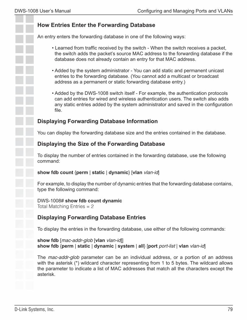
��
DWS-1008 User’s Manual
D-Link Systems, Inc.
Configuring and Managing Ports and VLANs
How Entries Enter the Forwarding Database
An entry enters the forwarding database in one of the following ways:
• Learned from traffic received by the switch - When the switch receives a packet, the switch adds the packet’s source MAC address to the forwarding database if the database does not already contain an entry for that MAC address.
• Added by the system administrator - You can add static and permanent unicast entries to the forwarding database. (You cannot add a multicast or broadcast address as a permanent or static forwarding database entry.)
• Added by the DWS-1008 switch itself - For example, the authentication protocols can add entries for wired and wireless authentication users. The switch also adds any static entries added by the system administrator and saved in the configuration file.
Displaying Forwarding Database Information
You can display the forwarding database size and the entries contained in the database.
Displaying the Size of the Forwarding Database
To display the number of entries contained in the forwarding database, use the following command:
show fdb count {perm | static | dynamic} [vlan vlan-id]
For example, to display the number of dynamic entries that the forwarding database contains, type the following command:
DWS-1008# show fdb count dynamicTotal Matching Entries = 2
Displaying Forwarding Database Entries
To display the entries in the forwarding database, use either of the following commands:
show fdb [mac-addr-glob [vlan vlan-id]]show fdb {perm | static | dynamic | system | all} [port port-list | vlan vlan-id]
The mac-addr-glob parameter can be an individual address, or a portion of an address with the asterisk (*) wildcard character representing from 1 to 5 bytes. The wildcard allows the parameter to indicate a list of MAC addresses that match all the characters except the asterisk.
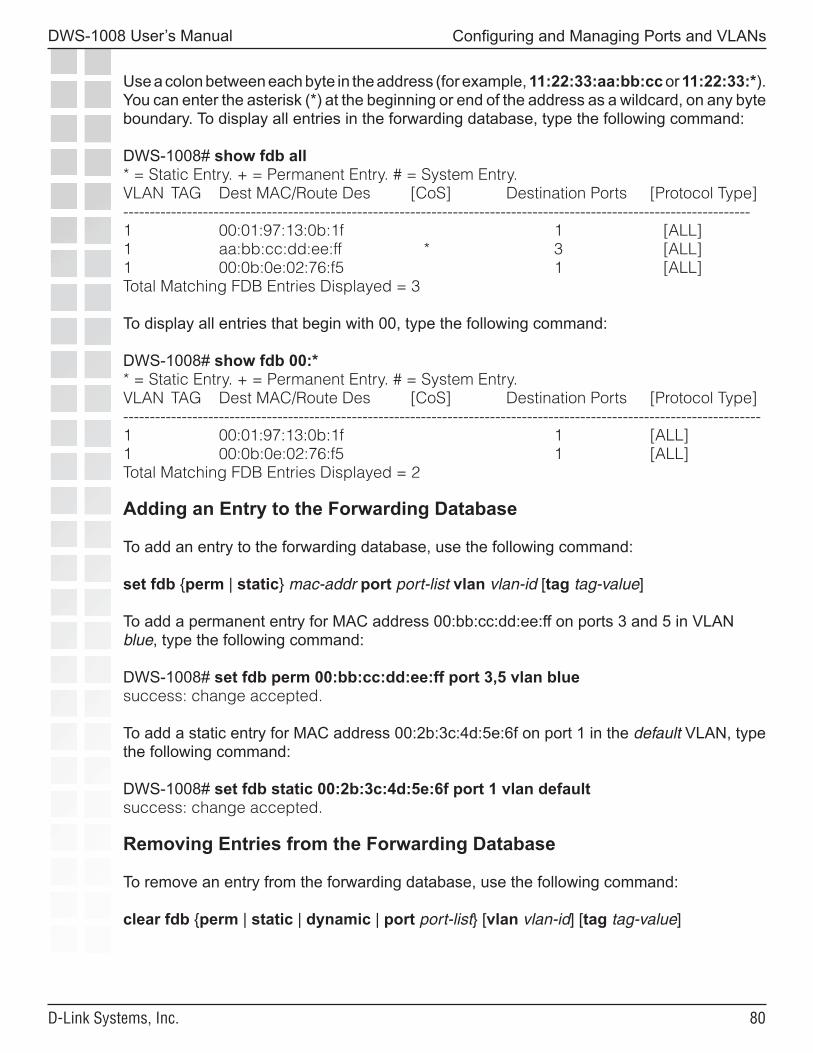
�0
DWS-1008 User’s Manual
D-Link Systems, Inc.
Configuring and Managing Ports and VLANs
Use a colon between each byte in the address (for example, 11:22:33:aa:bb:cc or 11:22:33:*). You can enter the asterisk (*) at the beginning or end of the address as a wildcard, on any byte boundary. To display all entries in the forwarding database, type the following command:
DWS-1008# show fdb all* = Static Entry. + = Permanent Entry. # = System Entry.VLAN TAG Dest MAC/Route Des [CoS] Destination Ports [Protocol Type]----------------------------------------------------------------------------------------------------------------------1 00:01:97:13:0b:1f 1 [ALL]1 aa:bb:cc:dd:ee:ff * 3 [ALL]1 00:0b:0e:02:76:f5 1 [ALL]Total Matching FDB Entries Displayed = 3
To display all entries that begin with 00, type the following command:
DWS-1008# show fdb 00:** = Static Entry. + = Permanent Entry. # = System Entry.VLAN TAG Dest MAC/Route Des [CoS] Destination Ports [Protocol Type]------------------------------------------------------------------------------------------------------------------------1 00:01:97:13:0b:1f 1 [ALL]1 00:0b:0e:02:76:f5 1 [ALL]Total Matching FDB Entries Displayed = 2
Adding an Entry to the Forwarding Database
To add an entry to the forwarding database, use the following command:
set fdb {perm | static} mac-addr port port-list vlan vlan-id [tag tag-value]
To add a permanent entry for MAC address 00:bb:cc:dd:ee:ff on ports 3 and 5 in VLAN blue, type the following command:
DWS-1008# set fdb perm 00:bb:cc:dd:ee:ff port 3,5 vlan bluesuccess: change accepted.
To add a static entry for MAC address 00:2b:3c:4d:5e:6f on port 1 in the default VLAN, type the following command:
DWS-1008# set fdb static 00:2b:3c:4d:5e:6f port 1 vlan defaultsuccess: change accepted.
Removing Entries from the Forwarding Database
To remove an entry from the forwarding database, use the following command:
clear fdb {perm | static | dynamic | port port-list} [vlan vlan-id] [tag tag-value]
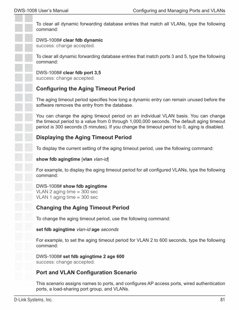
��
DWS-1008 User’s Manual
D-Link Systems, Inc.
Configuring and Managing Ports and VLANs
To clear all dynamic forwarding database entries that match all VLANs, type the following command:
DWS-1008# clear fdb dynamicsuccess: change accepted.
To clear all dynamic forwarding database entries that match ports 3 and 5, type the following command:
DWS-1008# clear fdb port 3,5success: change accepted.
Configuring the Aging Timeout Period
The aging timeout period specifies how long a dynamic entry can remain unused before the software removes the entry from the database.
You can change the aging timeout period on an individual VLAN basis. You can change the timeout period to a value from 0 through 1,000,000 seconds. The default aging timeout period is 300 seconds (5 minutes). If you change the timeout period to 0, aging is disabled.
Displaying the Aging Timeout Period
To display the current setting of the aging timeout period, use the following command:
show fdb agingtime [vlan vlan-id]
For example, to display the aging timeout period for all configured VLANs, type the following command:
DWS-1008# show fdb agingtimeVLAN 2 aging time = 300 secVLAN 1 aging time = 300 sec
Changing the Aging Timeout Period
To change the aging timeout period, use the following command:
set fdb agingtime vlan-id age seconds
For example, to set the aging timeout period for VLAN 2 to 600 seconds, type the following command:
DWS-1008# set fdb agingtime 2 age 600success: change accepted.
Port and VLAN Configuration Scenario
This scenario assigns names to ports, and configures AP access ports, wired authentication ports, a load-sharing port group, and VLANs.
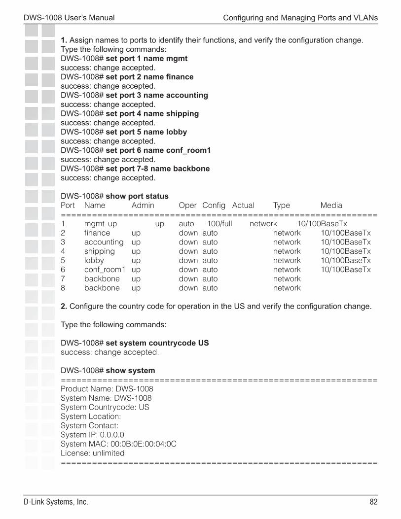
��
DWS-1008 User’s Manual
D-Link Systems, Inc.
Configuring and Managing Ports and VLANs
1. Assign names to ports to identify their functions, and verify the configuration change. Type the following commands:DWS-1008# set port 1 name mgmtsuccess: change accepted.DWS-1008# set port 2 name financesuccess: change accepted.DWS-1008# set port 3 name accountingsuccess: change accepted.DWS-1008# set port 4 name shippingsuccess: change accepted.DWS-1008# set port 5 name lobbysuccess: change accepted.DWS-1008# set port 6 name conf_room1success: change accepted.DWS-1008# set port 7-8 name backbonesuccess: change accepted.
DWS-1008# show port statusPort Name Admin Oper Config Actual Type Media=============================================================1 mgmt up up auto 100/full network 10/100BaseTx2 finance up down auto network 10/100BaseTx3 accounting up down auto network 10/100BaseTx4 shipping up down auto network 10/100BaseTx5 lobby up down auto network 10/100BaseTx6 conf_room1 up down auto network 10/100BaseTx7 backbone up down auto network8 backbone up down auto network
2. Configure the country code for operation in the US and verify the configuration change.
Type the following commands:
DWS-1008# set system countrycode USsuccess: change accepted.
DWS-1008# show system=============================================================Product Name: DWS-1008System Name: DWS-1008System Countrycode: USSystem Location:System Contact:System IP: 0.0.0.0System MAC: 00:0B:0E:00:04:0CLicense: unlimited=============================================================
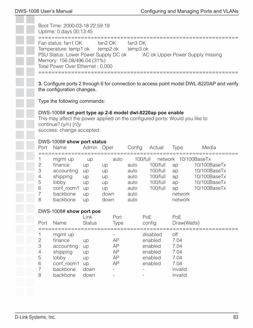
��
DWS-1008 User’s Manual
D-Link Systems, Inc.
Configuring and Managing Ports and VLANs
Boot Time: 2000-03-18 22:59:19Uptime: 0 days 00:13:45=============================================================Fan status: fan1 OK fan2 OK fan3 OKTemperature: temp1 ok temp2 ok temp3 okPSU Status: Lower Power Supply DC ok AC ok Upper Power Supply missingMemory: 156.08/496.04 (31%)Total Power Over Ethernet : 0.000=============================================================
3. Configure ports 2 through 6 for connection to access point model DWL-8220AP and verify the configuration changes.
Type the following commands:
DWS-1008# set port type ap 2-6 model dwl-8220ap poe enableThis may affect the power applied on the configured ports. Would you like tocontinue? (y/n) [n]ysuccess: change accepted.
DWS-1008# show port statusPort Name Admin Oper Config Actual Type Media=============================================================1 mgmt up up auto 100/full network 10/100BaseTx2 finance up up auto 100/full ap 10/100BaseTx3 accounting up up auto 100/full ap 10/100BaseTx4 shipping up up auto 100/full ap 10/100BaseTx5 lobby up up auto 100/full ap 10/100BaseTx6 conf_room1 up up auto 100/full ap 10/100BaseTx7 backbone up down auto network8 backbone up down auto network
DWS-1008# show port poe Link Port PoE PoEPort Name Status Type config Draw(Watts)=============================================================1 mgmt up - disabled off2 finance up AP enabled 7.043 accounting up AP enabled 7.044 shipping up AP enabled 7.045 lobby up AP enabled 7.046 conf_room1 up AP enabled 7.047 backbone down - - invalid8 backbone down - - invalid
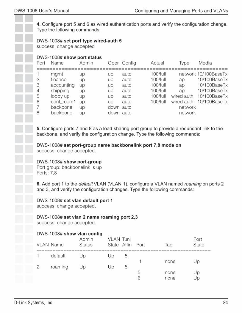
��
DWS-1008 User’s Manual
D-Link Systems, Inc.
Configuring and Managing Ports and VLANs
4. Configure port 5 and 6 as wired authentication ports and verify the configuration change. Type the following commands:
DWS-1008# set port type wired-auth 5success: change accepted
DWS-1008# show port statusPort Name Admin Oper Config Actual Type Media=============================================================1 mgmt up up auto 100/full network 10/100BaseTx2 finance up up auto 100/full ap 10/100BaseTx3 accounting up up auto 100/full ap 10/100BaseTx4 shipping up up auto 100/full ap 10/100BaseTx5 lobby up up up auto 100/full wired auth 10/100BaseTx6 conf_room1 up up auto 100/full wired auth 10/100BaseTx7 backbone up down auto network8 backbone up down auto network
5. Configure ports 7 and 8 as a load-sharing port group to provide a redundant link to the backbone, and verify the configuration change. Type the following commands:
DWS-1008# set port-group name backbonelink port 7,8 mode onsuccess: change accepted.
DWS-1008# show port-groupPort group: backbonelink is upPorts: 7,8
6. Add port 1 to the default VLAN (VLAN 1), configure a VLAN named roaming on ports 2 and 3, and verify the configuration changes. Type the following commands:
DWS-1008# set vlan default port 1success: change accepted.
DWS-1008# set vlan 2 name roaming port 2,3success: change accepted.
DWS-1008# show vlan config Admin VLAN Tunl PortVLAN Name Status State Affin Port Tag State--------------------------------------------------------------------------------------------------------------1 default Up Up 5 1 none Up2 roaming Up Up 5 5 none Up 6 none Up
��
DWS-1008 User’s Manual
D-Link Systems, Inc.
Configuring and Managing Ports and VLANs
7. Save the configuration. Type the following command:
DWS-1008# save configsuccess: configuration saved.
��
DWS-1008 User’s Manual
D-Link Systems, Inc.
Configuring and Managing IP Interfaces and Services
Configuring and Managing IP Interfaces and Services
MTU Support
Mobility System Software (MSS) supports standard maximum transmission units (MTUs) of 1514 bytes for standard Ethernet packets and 1518 bytes for Ethernet packets with an 802.1Q tag. MSS does not support changing of the MTU through software configuration, and MSS does not do path MTU discovery.
Encapsulation of the packets for tunneling adds an additional 44 bytes to the packet headers, so MSS does fragment and reassemble the packets if necessary to fit within the supported MTUs. However, MSS does not support defragmentation except at the receiving end of an IP tunnel, and only to reassemble fragments created by another D-Link device for tunneling.
If the path MTU between D-Link devices is less than 1448 bytes, a device in the path might further fragment or drop a tunneled packet. If the packet is further fragmented, the receiving switch will not be able to reassemble the fragments, and the packet is dropped.
Configuring and Managing IP InterfacesMany features, including the following, require an IP interface on the Switch:
• Management access through Telnet
IP interfaces are associated with VLANs. At least one VLAN on an Switch must have an IP interface to provide management access. Optionally, the other VLANs configured on the switch also can each have an IP interface. Each IP interface must belong to a unique, nonoverlapping IP subnet.
��
DWS-1008 User’s Manual
D-Link Systems, Inc.
Configuring and Managing IP Interfaces and Services
Adding an IP Interface
You can add an IP interface to a VLAN by statically configuring an IP address or by enabling the Dynamic Host Configuration Protocol (DHCP) client on the VLAN.
Statically Configuring an IP Interface
To add an IP interface to a VLAN, use the following command:
set interface vlan-id ip {ip-addr mask | ip-addr/mask-length}
Enabling the DHCP Client
The MSS DHCP client enables an Switch to obtain its IP configuration from a DHCP server. A switch can use the DHCP client to obtain the following configuration information:
• IP address • Default gateway • DNS domain name • DNS server IP address
The DHCP client is implemented according to “RFC 2131: Dynamic Host Configuration Protocol” and “RFC 2132: DHCP Options and BOOTP Vendor Extensions”. The client supports the following options:
• (12) Host Name (the system name) • (55) Parameter request list, consisting of (1) Subnet Mask, (3) Router, (15) Domain Name, and (6) Domain Name Server • (60) Vendor Class Identifier, set to TRPZ x.x.x, where x.x.x is the MSS version
The DHCP client is disabled by default on the DWS-1008, You can enable the DHCP client on one VLAN only.
MSS also has a configurable DHCP server. You can configure a DHCP client and DHCP server on the same VLAN, but only the client or the server can be enabled. The DHCP client and DHCP server cannot both be enabled on the same VLAN at the same time.
How MSS Resolves Conflicts with Statically Configured IP Parameters
MSS compares the IP parameter values already configured on the switch with the values received from the DHCP server, and resolves any conflicts as follows:
• IP address - If the VLAN also has a statically configured IP address, MSS uses an address from the DHCP server instead of the statically configured address. MSS sends an ARP for the IP address offered by the DHCP server to verify that the address is not already in use.
��
DWS-1008 User’s Manual
D-Link Systems, Inc.
Configuring and Managing IP Interfaces and Services
• If the address is not in use, MSS configures the VLAN that has the DHCP client enabled with the IP address received from the DHCP server. MSS then configures the other values as follows:
• Default gateway - MSS adds a default route for the gateway, with a metric of 10.
• DNS domain name and DNS server IP address - If the default domain name and DNS server IP address are already configured on the switch, and DNS is enabled, the configured values are used. Otherwise, the values received from the DHCP server are used.
• If the address offered by the DHCP server is already in use, MSS sends a DHCP Decline message to the server and generates a log message.
• If the address is in a subnet that is already configured on another VLAN on the switch, MSS sends a DHCP Decline message to the server and generates a log message.
If the switch is powered down or restarted, MSS does not retain the values received from the DHCP server. However, if the IP interface goes down but MSS is still running, MSS attempts to reuse the address when the interface comes back up.
Configuring the DHCP Client
To configure the DHCP client on a VLAN, use the following command:
set interface vlan-id ip dhcp-client {enable | disable}
The vlan-id can be the VLAN name or number.
The following command enables the DHCP client on VLAN corpvlan:
DWS-1008# set interface corpvlan ip dhcp-client enablesuccess: change accepted.
You can configure the DHCP client on more than one VLAN, but the client can be active on only one VLAN.
To remove all IP information from a VLAN, including the DHCP client and user-configured DHCP server, use the following command:
clear interface vlan-id ip
��
DWS-1008 User’s Manual
D-Link Systems, Inc.
Configuring and Managing IP Interfaces and Services
The IP interface table flags the address assigned by a DHCP server with an asterisk ( * ). In the following example, VLAN corpvlan received IP address 10.3.1.110 from a DHCP server.
DWS-1008# show interface* = From DHCPVLAN Name Address Mask Enabled State RIB--------------------------------------------------------------------------------------------------------------------4 corpvlan *10.3.1.110 255.255.255.0 YES Up ipv4
Displaying DHCP Client Information
To display DHCP client information, type the following command:
DWS-1008# show dhcp-client Interface: corpvlan(4) Configuration Status: Enabled DHCP State: IF_UP Lease Allocation: 65535 seconds Lease Remaining: 65532 seconds IP Address: 10.3.1.110 Subnet Mask: 255.255.255.0 Default Gateway: 10.3.1.1 DHCP Server: 10.3.1.4 DNS Servers: 10.3.1.29 DNS Domain Name: mycorp.com
Disabling or Reenabling an IP Interface
IP interfaces are enabled by default. To administratively disable or reenable an IP interface, use the following command:
set interface vlan-id status {up | down}
Removing an IP Interface
To remove an IP interface, use the following command:
clear interface vlan-id ip
Note: If you remove the IP interface that is being used as the system IP address, features that require the system IP address will not work correctly.
Displaying IP Interface Information
To display IP interface information, use the following command:
show interface [vlan-id]
�0
DWS-1008 User’s Manual
D-Link Systems, Inc.
Configuring and Managing IP Interfaces and Services
Configuring the System IP Address
You can designate one of the IP addresses configured on an Switch to be the system IP address of the switch. The system IP address determines the interface or source IP address MSS uses for system tasks, including the following:
• Topology reporting for dual-homed access points • Default source IP address used in unsolicited communications such as AAA accounting reports and SNMP traps
Designating the System IP Address
To designate the system IP address, use the following command:
set system ip-address ip-addr
Displaying the System IP Address
To display the system IP address, use the following command.
show system
Clearing the System IP Address
To clear the system IP address, use the following command:
clear system ip-address
Configuring and Managing IP Routes
The IP route table contains routes that MSS uses for determining the interfaces for a switch’s external communications. When you add an IP interface to a VLAN that is up, MSS automatically adds corresponding entries to the IP route table.
For destination routes that are not directly attached, you can add static routes. A static route specifies the destination and the gateway router through which to forward traffic.You can add the following types of static routes:
• Explicit route - Forwarding path for traffic to a specific destination • Default route - Forwarding path for traffic to a destination without an explicit route in the route table
A destination can be a subnet or network. If two static routes specify a destination, the more specific route is always chosen (longest prefix match). For example, if you have a static route with a destination of 10.10.1.0/24, and another static route with a destination of 10.10.0.0/16, the first static route is chosen to reach 10.10.1.15, because it has the longer prefix match.
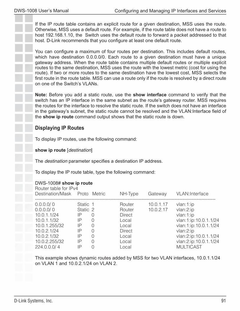
��
DWS-1008 User’s Manual
D-Link Systems, Inc.
Configuring and Managing IP Interfaces and Services
If the IP route table contains an explicit route for a given destination, MSS uses the route. Otherwise, MSS uses a default route. For example, if the route table does not have a route to host 192.168.1.10, the Switch uses the default route to forward a packet addressed to that host. D-Link recommends that you configure at least one default route.
You can configure a maximum of four routes per destination. This includes default routes, which have destination 0.0.0.0/0. Each route to a given destination must have a unique gateway address. When the route table contains multiple default routes or multiple explicit routes to the same destination, MSS uses the route with the lowest metric (cost for using the route). If two or more routes to the same destination have the lowest cost, MSS selects the first route in the route table. MSS can use a route only if the route is resolved by a direct route on one of the Switch’s VLANs.
Note: Before you add a static route, use the show interface command to verify that the switch has an IP interface in the same subnet as the route’s gateway router. MSS requires the routes for the interface to resolve the static route. If the switch does not have an interface in the gateway’s subnet, the static route cannot be resolved and the VLAN:Interface field of the show ip route command output shows that the static route is down.
Displaying IP Routes
To display IP routes, use the following command:
show ip route [destination]
The destination parameter specifies a destination IP address.
To display the IP route table, type the following command:
DWS-1008# show ip routeRouter table for IPv4Destination/Mask Proto Metric NH-Type Gateway VLAN:Interface-------------------------------------------------------------------------------------------------------------------0.0.0.0/ 0 Static 1 Router 10.0.1.17 vlan:1:ip0.0.0.0/ 0 Static 2 Router 10.0.2.17 vlan:2:ip10.0.1.1/24 IP 0 Direct vlan:1:ip10.0.1.1/32 IP 0 Local vlan:1:ip:10.0.1.1/2410.0.1.255/32 IP 0 Local vlan:1:ip:10.0.1.1/2410.0.2.1/24 IP 0 Direct vlan:2:ip10.0.2.1/32 IP 0 Local vlan:2:ip:10.0.1.1/2410.0.2.255/32 IP 0 Local vlan:2:ip:10.0.1.1/24224.0.0.0/ 4 IP 0 Local MULTICAST
This example shows dynamic routes added by MSS for two VLAN interfaces, 10.0.1.1/24 on VLAN 1 and 10.0.2.1/24 on VLAN 2.
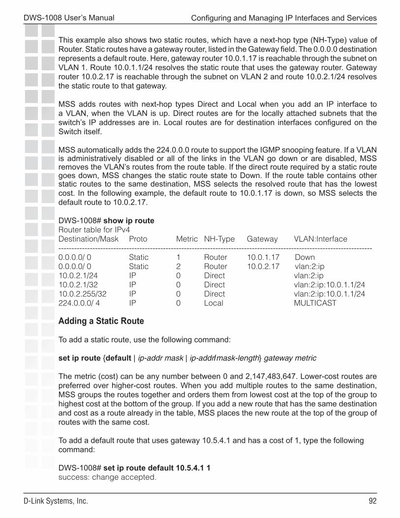
��
DWS-1008 User’s Manual
D-Link Systems, Inc.
Configuring and Managing IP Interfaces and Services
This example also shows two static routes, which have a next-hop type (NH-Type) value of Router. Static routes have a gateway router, listed in the Gateway field. The 0.0.0.0 destination represents a default route. Here, gateway router 10.0.1.17 is reachable through the subnet on VLAN 1. Route 10.0.1.1/24 resolves the static route that uses the gateway router. Gateway router 10.0.2.17 is reachable through the subnet on VLAN 2 and route 10.0.2.1/24 resolves the static route to that gateway.
MSS adds routes with next-hop types Direct and Local when you add an IP interface to a VLAN, when the VLAN is up. Direct routes are for the locally attached subnets that the switch’s IP addresses are in. Local routes are for destination interfaces configured on the Switch itself.
MSS automatically adds the 224.0.0.0 route to support the IGMP snooping feature. If a VLAN is administratively disabled or all of the links in the VLAN go down or are disabled, MSS removes the VLAN’s routes from the route table. If the direct route required by a static route goes down, MSS changes the static route state to Down. If the route table contains other static routes to the same destination, MSS selects the resolved route that has the lowest cost. In the following example, the default route to 10.0.1.17 is down, so MSS selects the default route to 10.0.2.17.
DWS-1008# show ip routeRouter table for IPv4Destination/Mask Proto Metric NH-Type Gateway VLAN:Interface------------------------------------------------------------------------------------------------------------------------0.0.0.0/ 0 Static 1 Router 10.0.1.17 Down0.0.0.0/ 0 Static 2 Router 10.0.2.17 vlan:2:ip10.0.2.1/24 IP 0 Direct vlan:2:ip10.0.2.1/32 IP 0 Direct vlan:2:ip:10.0.1.1/2410.0.2.255/32 IP 0 Direct vlan:2:ip:10.0.1.1/24224.0.0.0/ 4 IP 0 Local MULTICAST
Adding a Static Route
To add a static route, use the following command:
set ip route {default | ip-addr mask | ip-addr/mask-length} gateway metric
The metric (cost) can be any number between 0 and 2,147,483,647. Lower-cost routes are preferred over higher-cost routes. When you add multiple routes to the same destination, MSS groups the routes together and orders them from lowest cost at the top of the group to highest cost at the bottom of the group. If you add a new route that has the same destination and cost as a route already in the table, MSS places the new route at the top of the group of routes with the same cost.
To add a default route that uses gateway 10.5.4.1 and has a cost of 1, type the following command:
DWS-1008# set ip route default 10.5.4.1 1success: change accepted.
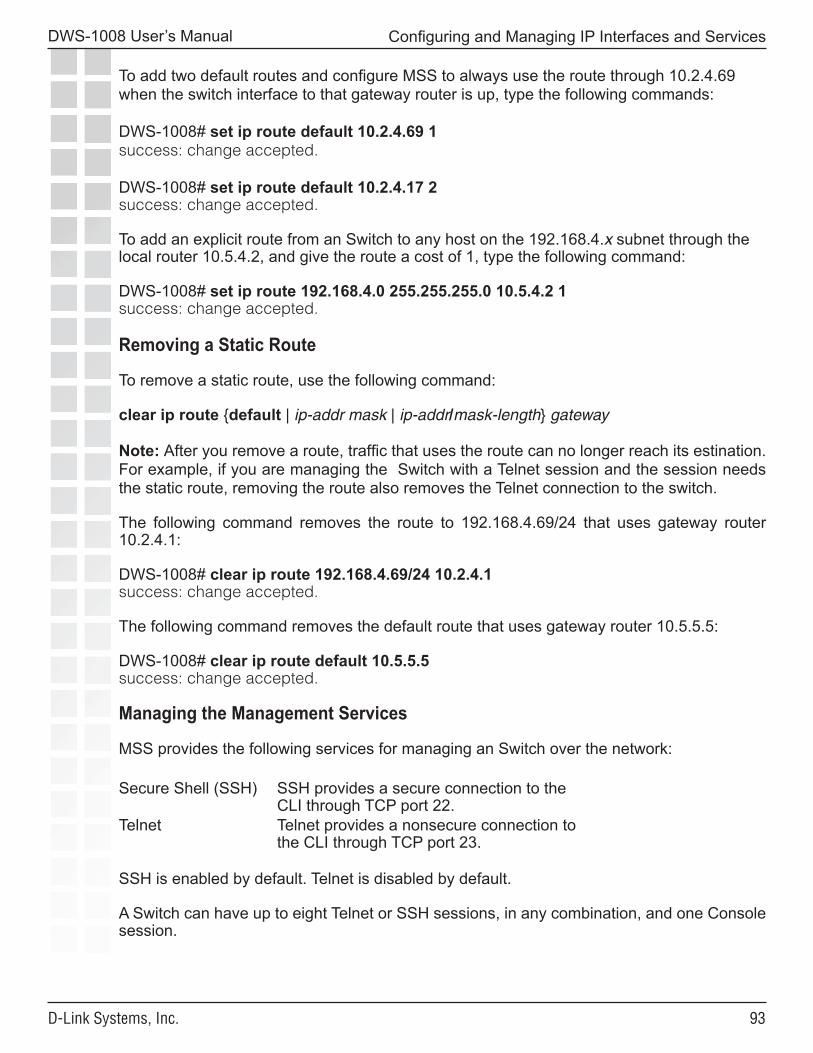
��
DWS-1008 User’s Manual
D-Link Systems, Inc.
Configuring and Managing IP Interfaces and Services
To add two default routes and configure MSS to always use the route through 10.2.4.69 when the switch interface to that gateway router is up, type the following commands:
DWS-1008# set ip route default 10.2.4.69 1success: change accepted.
DWS-1008# set ip route default 10.2.4.17 2success: change accepted.
To add an explicit route from an Switch to any host on the 192.168.4.x subnet through the local router 10.5.4.2, and give the route a cost of 1, type the following command:
DWS-1008# set ip route 192.168.4.0 255.255.255.0 10.5.4.2 1success: change accepted.
Removing a Static Route
To remove a static route, use the following command:
clear ip route {default | ip-addr mask | ip-addr/mask-length} gateway
Note: After you remove a route, traffic that uses the route can no longer reach its estination. For example, if you are managing the Switch with a Telnet session and the session needs the static route, removing the route also removes the Telnet connection to the switch.
The following command removes the route to 192.168.4.69/24 that uses gateway router 10.2.4.1:
DWS-1008# clear ip route 192.168.4.69/24 10.2.4.1success: change accepted.
The following command removes the default route that uses gateway router 10.5.5.5:
DWS-1008# clear ip route default 10.5.5.5success: change accepted.
Managing the Management Services
MSS provides the following services for managing an Switch over the network:
Secure Shell (SSH) SSH provides a secure connection to the CLI through TCP port 22.
Telnet Telnet provides a nonsecure connection to the CLI through TCP port 23.
SSH is enabled by default. Telnet is disabled by default.
A Switch can have up to eight Telnet or SSH sessions, in any combination, and one Console session.
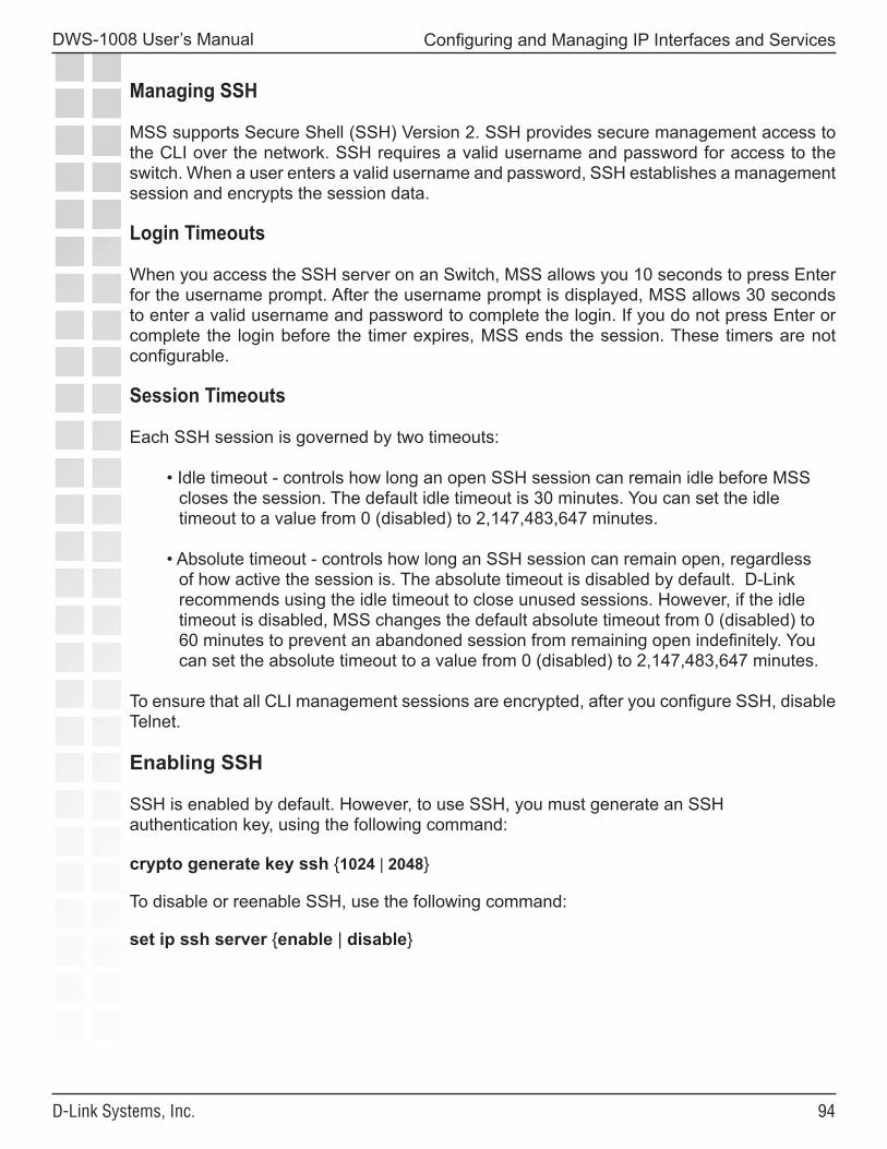
��
DWS-1008 User’s Manual
D-Link Systems, Inc.
Configuring and Managing IP Interfaces and Services
Managing SSH
MSS supports Secure Shell (SSH) Version 2. SSH provides secure management access to the CLI over the network. SSH requires a valid username and password for access to the switch. When a user enters a valid username and password, SSH establishes a management session and encrypts the session data.
Login Timeouts
When you access the SSH server on an Switch, MSS allows you 10 seconds to press Enter for the username prompt. After the username prompt is displayed, MSS allows 30 seconds to enter a valid username and password to complete the login. If you do not press Enter or complete the login before the timer expires, MSS ends the session. These timers are not configurable.
Session Timeouts
Each SSH session is governed by two timeouts:
• Idle timeout - controls how long an open SSH session can remain idle before MSS closes the session. The default idle timeout is 30 minutes. You can set the idle timeout to a value from 0 (disabled) to 2,147,483,647 minutes.
• Absolute timeout - controls how long an SSH session can remain open, regardless of how active the session is. The absolute timeout is disabled by default. D-Link recommends using the idle timeout to close unused sessions. However, if the idle timeout is disabled, MSS changes the default absolute timeout from 0 (disabled) to 60 minutes to prevent an abandoned session from remaining open indefinitely. You can set the absolute timeout to a value from 0 (disabled) to 2,147,483,647 minutes.
To ensure that all CLI management sessions are encrypted, after you configure SSH, disable Telnet.
Enabling SSH
SSH is enabled by default. However, to use SSH, you must generate an SSH authentication key, using the following command:
crypto generate key ssh {1024 | 2048}
To disable or reenable SSH, use the following command:
set ip ssh server {enable | disable}
��
DWS-1008 User’s Manual
D-Link Systems, Inc.
Configuring and Managing IP Interfaces and Services
You must generate an SSH authentication key before you can enable SSH. You need to generate the key only once. The key must be at least 1024 bytes long. The Switch stores the key in nonvolatile storage where the key remains even after software reboots. To generate a 1024-byte SSH authentication key, type the following command:
DWS-1008# crypto generate key ssh 1024key pair generated
You can verify the key using the following command:
show crypto key ssh
For example:
DWS-1008# show crypto key sshec:6f:56:7f:d1:fd:c0:28:93:ae:a4:f9:7c:f5:13:04
This command displays the checksum (also called a fingerprint) of the public key. When you initially connect to the Switch with an SSH client, you can compare the SSH key checksum displayed by the Switch with the one displayed by the client to verify that you really are connected to the Switch and not another device. Generally, SSH clients remember the encryption key after the first connection, so you need to check the key only once.
Adding an SSH User
To log in with SSH, a user must supply a valid username and password. To add a username and password to the local database, use the following command:
set user username password password
Optionally, you also can configure MSS either to locally authenticate the user or to use a RADIUS server to authenticate the user. Use the following command:
set authentication admin {user-glob} method1 [method2] [method3] [method4]
To add administrative user admin with password letmein, and use RADIUS server group sg1 to authenticate the user, type the following commands:
DWS-1008# set user admin password letmeinsuccess: User admin created
DWS-1008# set authentication admin admin sg1success: change accepted
��
DWS-1008 User’s Manual
D-Link Systems, Inc.
Configuring and Managing IP Interfaces and Services
Changing the SSH Service Port Number
To change the SSH port the Switch listens on for SSH connections, use the following command:
set ip ssh port port-num
Caution: If you change the SSH port number from an SSH session, MSS immediately ends the session. To open a new management session, you must configure the SSH client to use the new SSH port number.
Changing SSH Timeouts
To change the SSH timeout values, use the following commands:
set ip ssh idle-timeout minutesset ip ssh absolute-timeout minutes
To change the absolute timeout value to 30 minutes, type the following command:
DWS-1008# set ip ssh absolute-timeout 30success: absolute timeout set to 30 minutes
Managing SSH Server Sessions
Use the following commands to manage SSH server sessions:
show sessions adminclear sessions admin ssh [session-id]
These commands display and clear SSH server sessions.
Note: If you type the clear sessions admin ssh command from within an SSH session, the session ends as soon as you press Enter.
To display the SSH server sessions on an Switch, type the following command:
DWS-1008# show sessions adminTty Username Time (s) Type------- -------------------- ----------- -----------tty0 3644 Consoletty2 tech 6 Telnettty3 sshadmin 381 SSH
3 admin sessions
To clear all SSH server sessions, type the following command:
DWS-1008# clear sessions admin sshThis will terminate manager sessions, do you wish to continue? (y|n) [n]yCleared ssh session on tty3
��
DWS-1008 User’s Manual
D-Link Systems, Inc.
Configuring and Managing IP Interfaces and Services
Managing Telnet
Telnet requires a valid username and password for access to the switch.
Telnet Login Timers
After the username prompt is displayed, MSS allows 30 seconds to enter a valid username and password to complete the login. If you do not press Enter or complete the login before the timer expires, MSS ends the session. This timer is not configurable.
Enabling Telnet
Telnet is disabled by default. To enable Telnet, use the following command:
set ip telnet server {enable | disable}
Adding a Telnet User
To log in with Telnet, a user must supply a valid username and password. To add a username and password to the local database, use the following command:
set user username password password
Optionally, you also can configure MSS either to locally authenticate the user or to use a RADIUS server to authenticate the user. Use the following command:
set authentication admin {user-glob} method1 [method2] [method3] [method4]
You can use the same username and password for SSH or create a new one. For a CLI example, see Adding an SSH User.
Displaying Telnet Status
To display the status of the Telnet server, use the following command:
show ip telnet
To display the Telnet server status and the TCP port number on which an Switch listens for Telnet traffic, type the following command:
DWS-1008> show ip telnet
Server Status Port--------------------------------------Enabled 23
��
DWS-1008 User’s Manual
D-Link Systems, Inc.
Configuring and Managing IP Interfaces and Services
Changing the Telnet Service Port Number
To change the TCP port the Switch listens on for Telnet connections, use the following command:
set ip telnet port-num
Caution: If you change the Telnet port number from a Telnet session, MSS immediately ends the session. To open a new management session, you must Telnet to the switch with the new Telnet port number.
Resetting the Telnet Service Port Number to Its Default
To reset the Telnet management service to its default TCP port, use the following command:
clear ip telnet
Managing Telnet Server Sessions
Use the following commands to manage Telnet server sessions:
show sessions adminclear sessions admin telnet [session-id]
These commands display and clear management sessions from a remote client to the switch’s Telnet server.
To display the Telnet server sessions on an Switch, type the following command:
Note. If you type the clear sessions admin telnet command from within a Telnet session, the session ends as soon as you press Enter.
DWS-1008# show sessions adminTty Username Time (s) Type------- -------------------- ----------- --------tty0 3644 Consoletty2 tech 6 Telnettty3 sshadmin 381 SSH
3 admin sessions
To clear all Telnet server sessions, type the following command:
DWS-1008# clear sessions telnetThis will terminate manager sessions, do you wish to continue? (y|n) [n]yCleared telnet session on tty2

��
DWS-1008 User’s Manual
D-Link Systems, Inc.
Configuring and Managing IP Interfaces and Services
Configuring and Managing DNS
You can configure an Switch to use a Domain Name Service (DNS) server to resolve hostnames into their IP addresses. This capability is useful in cases where you specify a hostname instead of an IP address in a command.
For example, as an alternative to the command ping 192.168.9.1, you can enter the command ping chris.example.com. When you enter ping chris.example.com, the Switch’s DNS client queries a DNS server for the IP address that corresponds to the hostname chris.example.com, then sends the ping request to that IP address.
The Switch’s DNS client is disabled by default. To configure DNS:
• Enable the DNS client. • Specify the IP addresses of the DNS servers. • Configure a default domain name for DNS queries.
�00
DWS-1008 User’s Manual
D-Link Systems, Inc.
Configuring and Managing IP Interfaces and Services
Enabling or Disabling the DNS Client
The DNS client is disabled by default. To enable or disable the DNS client, use the following command:
set ip dns {enable | disable}
Configuring DNS Servers
You can configure an Switch to use one primary DNS server and up to five secondary DNS servers to resolve DNS queries.
The Switch always sends a request to the primary DNS server first. The Switch sends a request to a secondary DNS server only if the primary DNS server does not respond.
Adding a DNS Server
To add a DNS server, use the following command:
set ip dns server ip-addr {primary | secondary}
Removing a DNS Server
To remove a DNS server, use the following command:
clear ip dns server ip-addr
Configuring a Default Domain Name
You can configure a single default domain name for DNS queries. The Switch appends the default domain name to hostnames you enter in commands. For example, you can configure the Switch to automatically append the domain name example.com to any hostname that does not have a domain name. In this case, you can enter ping chris instead of ping chris.example.com, and the Switch automatically requests the DNS server to send the IP address for chris.example.com.
To override the default domain name when entering a hostname in a CLI command, enter a period at the end of the hostname. For example, if the default domain name is example.com, enter chris. if the hostname is chris and not chris.example.com.
Aliases take precedence over DNS. When you enter a hostname, MSS checks for an alias with that name first, before using DNS to resolve the name.
�0�
DWS-1008 User’s Manual
D-Link Systems, Inc.
Configuring and Managing IP Interfaces and Services
Adding the Default Domain Name
To add the default domain name, use the following command:
set ip dns domain name
Specify a domain name of up to 64 alphanumeric characters.
Removing the Default Domain Name
To remove the default domain name, use the following command:
clear ip dns domain
Displaying DNS Server Information
To display DNS server information, use the following command:
show ip dns
The following example shows DNS server information on a switch configured to use three DNS servers.
DWS-1008# show ip dnsDomain Name: example.comDNS Status: enabledIP Address Type--------------------------------------------10.1.1.1 PRIMARY10.1.1.2 SECONDARY10.1.2.1 SECONDARY
Configuring and Managing Aliases
An alias is a string that represents an IP address. You can use aliases as shortcuts in CLI commands. For example, you can configure alias pubs1 for IP address 10.10.10.20, and enter ping pubs1 as a shortcut for ping 10.10.10.20.
Aliases take precedence over DNS. When you enter a hostname, MSS checks for an alias with that name first, before using DNS to resolve the name.
�0�
DWS-1008 User’s Manual
D-Link Systems, Inc.
Configuring and Managing IP Interfaces and Services
Adding an Alias
To add an alias, use the following command:
set ip alias name ip-addr
Specify an alias of up to 32 alphanumeric characters.
To add an alias HR1 for IP address 192.168.1.2, type the following command:
DWS-1008# set ip alias HR1 192.168.1.2success: change accepted.
After configuring the alias, you can use HR1 in commands in place of the IP address. For example, to ping 192.168.1.2, you can type the command ping HR1.Removing an Alias
To remove an alias, use the following command:
clear ip alias name
Displaying Aliases
To display aliases, use the following command:
show ip alias [name]
Here is an example:
DWS-1008# show ip aliasName IP Address------------ --------------------HR1 192.168.1.2payroll 192.168.1.3radius1 192.168.7.2
Configuring and Managing Time Parameters
You can configure the system time and date statically or by using Network Time Protocol (NTP) servers. In each case, you can specify the offset from Coordinated Universal Time (UTC) by setting the time zone. You also can configure MSS to offset the time by an additional hour for daylight savings time or similar summertime period.
Note. D-Link recommends that you set the time and date parameters before you install certificates on the switch. Generally, certificates are valid for one year beginning with the system time and date that are in effect when you generate the certificate request. If the switch’s time and date are incorrect, the certificate might not be valid.
�0�
DWS-1008 User’s Manual
D-Link Systems, Inc.
Configuring and Managing IP Interfaces and Services
To statically set the time and date:
• Set the time zone (set timezone command) • Set the summertime period (set summertime command) • Set the time and date (set timedate command)
Note: Configure summertime before you set the time and date. Otherwise, summertime’s adjustment of the time will make the time incorrect, if the date is within the summertime period.To use NTP servers to set the time and date:
• Set the time zone (set timezone command) • Set the summertime period (set summertime command) • Configure NTP server information (set ntp commands)
Setting the Time Zone
The time zone parameter adjusts the system date, and optionally the time, by applying an offset to UTC.
To set the time zone, use the following command:
set timezone zone-name {-hours [minutes]}
The zone name can be up to 32 alphanumeric characters long, with no spaces. The hours parameter specifies the number of hours to add to or subtract from UTC. Use a minus sign (-) in front of the hour value to subtract the hours from UTC.
To set the time zone to PST (Pacific Standard Time), type the following command:
DWS-1008# set timezone PST -8Timezone is set to ‘PST’, offset from UTC is -8:0 hours.
Displaying the Time Zone
To display the time zone, use the following command:
show timezone
For example, to display the time zone, type the following command:
DWS-1008# show timezoneTimezone set to ‘PST’, offset from UTC is -8 hours
�0�
DWS-1008 User’s Manual
D-Link Systems, Inc.
Configuring and Managing IP Interfaces and Services
Clearing the Time Zone
To clear the time zone, use the following command:
clear timezone
Configuring the Summertime Period
The summertime period offsets the system time +1 hour and returns it to standard time for daylight savings time or a similar summertime period that you set.
Note: Configure summertime before you set the time and date. Otherwise, summertime’s adjustment of the time will make the time incorrect, if the date is within the summertime period.
To configure the summertime period, use the following command:
set summertime summer-name [start week weekday month hour min end week weekday month hour min]
The summer-name can be up to 32 alphanumeric characters long, with no spaces. The start and end dates and times are optional. If you do not specify a start and end time, MSS implements the time change starting at 2:00 a.m. on the first Sunday in April and ending at 2:00 a.m. on the last Sunday in October, according to the North American standard.
To set the summertime period to PDT (Pacific Daylight Time) and use the default start and end dates and times, type the following command:
DWS-1008# set summertime PDTsuccess: change accepted.
Displaying the Summertime Period
To display the summertime period, use the following command:
show summertime
For example, to display the summertime period, type the following command:
DWS-1008# show summertimeSummertime is enabled, and set to ‘PDT’. Start : Sun Apr 04 2004, 02:00:00 End : Sun Oct 31 2004, 02:00:00 Offset : 60 minutes Recurring : yes, starting at 2:00 am of first Sunday of April and ending at 2:00 am on last Sunday of October.
�0�
DWS-1008 User’s Manual
D-Link Systems, Inc.
Configuring and Managing IP Interfaces and Services
Clearing the Summertime Period
To clear the summertime period, use the following command:
clear summertime
Statically Configuring the System Time and Date
To statically configure the system time and date, use the following command:
set timedate {date mmm dd yyyy [time hh:mm:ss]}
The day of week is automatically calculated from the day you set.
To set the date to February 29, 2004 and time to 23:58:
DWS-1008# set timedate date feb 29 2004 time 23:58:00Time now is: Sun Feb 29 2004, 23:58:02 PST
The CLI makes the time change, then displays the current system time based on the change. (The time displayed might be slightly later than the time you enter due to the interval between when you press Enter and when the CLI reads and displays the new time and date.)
Displaying the Time and Date
To display the time and date, use the following command:
show timedate
DWS-1008# show timedateSun Feb 29 2004, 23:58:02 PST
Configuring and Managing NTP
The Network Time Protocol (NTP) allows a networking device to synchronize its system time and date with the time and date on an NTP server. When used on multiple devices, NTP ensures that the time and date are consistent among those devices.
The NTP implementation in MSS is based on RFC 1305, Network Time Protocol (Version 3) Specification, Implementation and Analysis.
You can configure a switch to consult up to three NTP servers. The switch compares the results from the servers and selects the best response. (For information, see RFC 1305.)
After you enable the NTP client and configure NTP servers, MSS queries the NTP servers for an update every 64 seconds and waits 15 seconds for a reply. If the switch does not receive a reply to an NTP query within 15 seconds, the switch tries again up to 16 times. You can change the update interval but not the timeout or number of retries.
�0�
DWS-1008 User’s Manual
D-Link Systems, Inc.
Configuring and Managing IP Interfaces and Services
MSS adjusts the NTP reply according to the following time parameters configured on the switch:
• Offset from UTC • Daylight savings time
The NTP client is disabled by default.
Adding an NTP Server
To add an NTP server to the list of NTP servers, use the following command:
set ntp server ip-addr
To configure an Switch to use NTP server 192.168.1.5, type the following command:
DWS-1008# set ntp server 192.168.1.5
Removing an NTP Server
To remove an NTP server, use the following command:
clear ntp server {ip-addr | all}
If you use the all option, MSS clears all NTP servers configured on the switch.
Changing the NTP Update Interval
The default update interval is 64 seconds. To change the update interval, use the following command:
set ntp update-interval seconds
You can specify an interval from 16 through 1024 seconds.
For example, to change the NTP update interval to 128 seconds, type the following command:
DWS-1008# set ntp update-interval 128success: change accepted.
�0�
DWS-1008 User’s Manual
D-Link Systems, Inc.
Configuring and Managing IP Interfaces and Services
Resetting the Update Interval to the Default
To reset the update interval to the default value, use the following command:
clear ntp update-interval
Enabling the NTP Client
The NTP client is disabled by default. To enable the NTP client, use the following command:
set ntp {enable | disable}
Displaying NTP Information
To display NTP information, use the following command:
show ntp
Here is an example:
DWS-1008> show ntpNTP client: enabledCurrent update-interval: 20(secs)Current time: Sun Feb 29 2004, 23:58:12Timezone is set to ‘PST’, offset from UTC is -8:0 hours.Summertime is enabled.Last NTP update: Sun Feb 29 2004, 23:58:00NTP Server Peer state Local State------------------------------------------------------------192.168.1.5 SYSPEER SYNCED
The Timezone and Summertime fields are displayed only if you change the timezone or enable summertime.
Managing the ARP Table
The Address Resolution Protocol (ARP) table maps IP addresses to MAC addresses. An ARP entry enters the table in one of the following ways:
• Added automatically by the Switch. A switch adds an entry for its own MAC address and adds entries for addresses learned from traffic received by the switch. When the switch receives an IP packet, the switch adds the packet’s source MAC address and source IP address to the ARP table.
• Added by the system administrator. You can add dynamic, static, and permanent entries to the ARP table.
ARP is enabled by default on a switch and cannot be disabled.

�0�
DWS-1008 User’s Manual
D-Link Systems, Inc.
Configuring and Managing IP Interfaces and Services
Displaying ARP Table Entries
To display ARP table entries, use the following command:
show arp [ip-addr]
Here is an example:
DWS-1008# show arpARP aging time: 1200 secondsHost HW Address VLAN Type State-------------------------------------------------------------------------------------------------------------10.5.4.51 00:0b:0e:02:76:f5 1 DYNAMIC RESOLVED10.5.4.53 00:0b:0e:02:76:f7 1 LOCAL RESOLVED
This example shows two entries. The local entry (with LOCAL in the Type field) is for the switch itself. The MAC address of the local entry is the switch’s MAC address. The ARP table contains one local entry for each VLAN configured on the switch. The dynamic entry is learned from traffic received by the switch. The ARP table can also contain static and permanent entries, which are added by an administrator. The State field indicates whether an entry is resolved (RESOLVED) or whether MSS has sent an ARP request for the entry and is waiting for the reply (RESOLVING).
Adding an ARP Entry
MSS automatically adds a local entry for a switch and dynamic entries for addresses learned from traffic received by the switch. You can add the following types of entries:
• Dynamic - Ages out based on the aging timeout.• Static - Does not age out but is removed by a software reboot.• Permanent - Does not age out and remains in the ARP table following a software
reboot.
To add an ARP entry, use the following command:
set arp {permanent | static | dynamic} ip-addr mac-addr
To add a static ARP entry that maps IP address 10.10.10.1 to MAC address 00:bb:cc:dd:ee:ff, type the following command:
DWS-1008# set arp static 10.10.10.1 00:bb:cc:dd:ee:ffsuccess: added arp 10.10.10.1 at 00:bb:cc:dd:ee:ff on VLAN 1
Changing the Aging Timeout
The aging timeout specifies how long a dynamic entry can remain unused before the software removes the entry from the ARP table. The default aging timeout is 1200 seconds (20 minutes). The aging timeout does not affect the local entry, static entries, or permanent entries.

�0�
DWS-1008 User’s Manual
D-Link Systems, Inc.
Configuring and Managing IP Interfaces and Services
To change the aging timeout, use the following command:
set arp agingtime seconds
You can specify from 0 to 1,000,000 seconds. To disable aging, specify 0.
For example, to disable aging of dynamic ARP entries, type the following command:
DWS-1008# set arp agingtime 0success: set arp aging time to 0 seconds
Note: To reset the ARP aging timeout to its default value, use the set arp agingtime 1200 command.
Pinging Another Device
To verify that another device in the network can receive IP packets sent by the Switch, use the following command:
ping host [count num-packets] [dnf] [flood] [interval time] [size size] [source-ip ip-addr | vlan-name]
To ping a device that has IP address 10.1.1.1, type the following command:
DWS-1008# ping 10.1.1.1PING 10.1.1.1 (10.1.1.1) from 10.9.4.34 : 56(84) bytes of data.64 bytes from 10.1.1.1: icmp_seq=1 ttl=255 time=0.769 ms64 bytes from 10.1.1.1: icmp_seq=2 ttl=255 time=0.628 ms64 bytes from 10.1.1.1: icmp_seq=3 ttl=255 time=0.676 ms64 bytes from 10.1.1.1: icmp_seq=4 ttl=255 time=0.619 ms64 bytes from 10.1.1.1: icmp_seq=5 ttl=255 time=0.608 ms--- 10.1.1.1 ping statistics ---5 packets transmitted, 5 packets received, 0 errors, 0% packet loss
In this example, the ping is successful, indicating that the Switch has IP connectivity with the other device.
Logging In to a Remote Device
From within an MSS console session or Telnet session, you can use the Telnet client to establish a Telnet client session from an Switch’s CLI to another device. To establish a Telnet client session with another device, use the following command:
telnet {ip-addr | hostname} [port port-num]
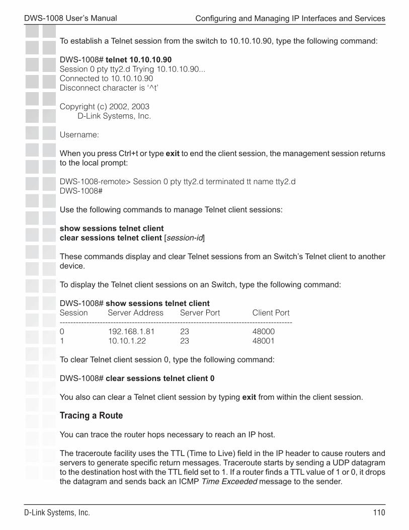
��0
DWS-1008 User’s Manual
D-Link Systems, Inc.
Configuring and Managing IP Interfaces and Services
To establish a Telnet session from the switch to 10.10.10.90, type the following command:
DWS-1008# telnet 10.10.10.90Session 0 pty tty2.d Trying 10.10.10.90...Connected to 10.10.10.90Disconnect character is ‘^t’
Copyright (c) 2002, 2003 D-Link Systems, Inc.
Username:
When you press Ctrl+t or type exit to end the client session, the management session returns to the local prompt:
DWS-1008-remote> Session 0 pty tty2.d terminated tt name tty2.dDWS-1008#
Use the following commands to manage Telnet client sessions:
show sessions telnet clientclear sessions telnet client [session-id]
These commands display and clear Telnet sessions from an Switch’s Telnet client to another device.
To display the Telnet client sessions on an Switch, type the following command:
DWS-1008# show sessions telnet clientSession Server Address Server Port Client Port---------------------------------------------------------------------------------------0 192.168.1.81 23 480001 10.10.1.22 23 48001
To clear Telnet client session 0, type the following command:
DWS-1008# clear sessions telnet client 0
You also can clear a Telnet client session by typing exit from within the client session.
Tracing a Route
You can trace the router hops necessary to reach an IP host.
The traceroute facility uses the TTL (Time to Live) field in the IP header to cause routers and servers to generate specific return messages. Traceroute starts by sending a UDP datagram to the destination host with the TTL field set to 1. If a router finds a TTL value of 1 or 0, it drops the datagram and sends back an ICMP Time Exceeded message to the sender.
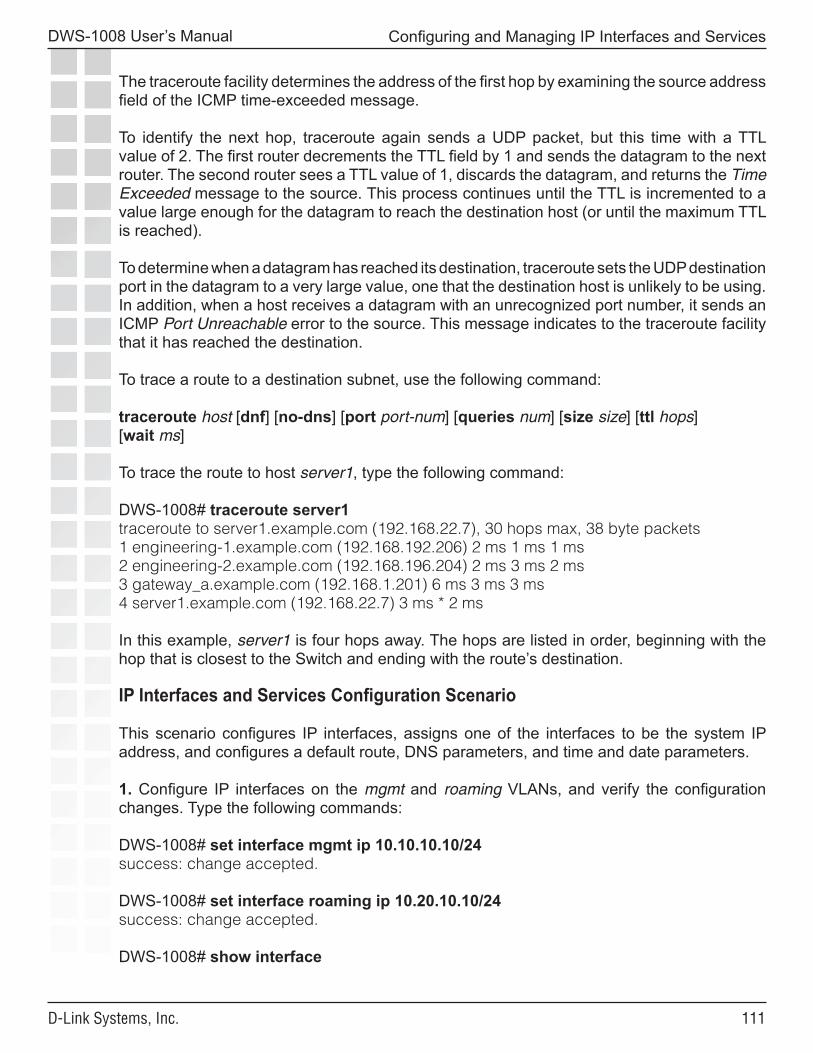
���
DWS-1008 User’s Manual
D-Link Systems, Inc.
Configuring and Managing IP Interfaces and Services
The traceroute facility determines the address of the first hop by examining the source address field of the ICMP time-exceeded message.
To identify the next hop, traceroute again sends a UDP packet, but this time with a TTL value of 2. The first router decrements the TTL field by 1 and sends the datagram to the next router. The second router sees a TTL value of 1, discards the datagram, and returns the Time Exceeded message to the source. This process continues until the TTL is incremented to a value large enough for the datagram to reach the destination host (or until the maximum TTL is reached).
To determine when a datagram has reached its destination, traceroute sets the UDP destination port in the datagram to a very large value, one that the destination host is unlikely to be using. In addition, when a host receives a datagram with an unrecognized port number, it sends an ICMP Port Unreachable error to the source. This message indicates to the traceroute facility that it has reached the destination.
To trace a route to a destination subnet, use the following command:
traceroute host [dnf] [no-dns] [port port-num] [queries num] [size size] [ttl hops][wait ms]
To trace the route to host server1, type the following command:
DWS-1008# traceroute server1traceroute to server1.example.com (192.168.22.7), 30 hops max, 38 byte packets1 engineering-1.example.com (192.168.192.206) 2 ms 1 ms 1 ms2 engineering-2.example.com (192.168.196.204) 2 ms 3 ms 2 ms3 gateway_a.example.com (192.168.1.201) 6 ms 3 ms 3 ms4 server1.example.com (192.168.22.7) 3 ms * 2 ms
In this example, server1 is four hops away. The hops are listed in order, beginning with the hop that is closest to the Switch and ending with the route’s destination.
IP Interfaces and Services Configuration Scenario
This scenario configures IP interfaces, assigns one of the interfaces to be the system IP address, and configures a default route, DNS parameters, and time and date parameters.
1. Configure IP interfaces on the mgmt and roaming VLANs, and verify the configuration changes. Type the following commands:
DWS-1008# set interface mgmt ip 10.10.10.10/24success: change accepted.
DWS-1008# set interface roaming ip 10.20.10.10/24success: change accepted.
DWS-1008# show interface
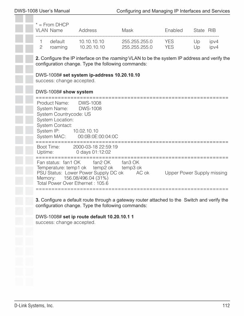
���
DWS-1008 User’s Manual
D-Link Systems, Inc.
Configuring and Managing IP Interfaces and Services
* = From DHCPVLAN Name Address Mask Enabled State RIB------------------------------------------------------------------------------------------------------------------- 1 default 10.10.10.10 255.255.255.0 YES Up ipv4 2 roaming 10.20.10.10 255.255.255.0 YES Up ipv4
2. Configure the IP interface on the roaming VLAN to be the system IP address and verify the configuration change. Type the following commands:
DWS-1008# set system ip-address 10.20.10.10success: change accepted.
DWS-1008# show system============================================================= Product Name: DWS-1008 System Name: DWS-1008 System Countrycode: US System Location: System Contact: System IP: 10.02.10.10 System MAC: 00:0B:0E:00:04:0C============================================================= Boot Time: 2000-03-18 22:59:19 Uptime: 0 days 01:12:02============================================================= Fan status: fan1 OK fan2 OK fan3 OK Temperature: temp1 ok temp2 ok temp3 ok PSU Status: Lower Power Supply DC ok AC ok Upper Power Supply missing Memory: 156.08/496.04 (31%) Total Power Over Ethernet : 105.6=============================================================
3. Configure a default route through a gateway router attached to the Switch and verify the configuration change. Type the following commands:
DWS-1008# set ip route default 10.20.10.1 1success: change accepted.
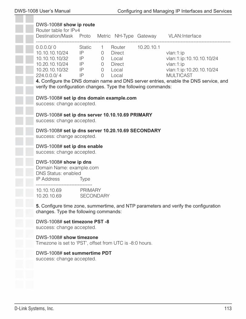
���
DWS-1008 User’s Manual
D-Link Systems, Inc.
Configuring and Managing IP Interfaces and Services
DWS-1008# show ip routeRouter table for IPv4Destination/Mask Proto Metric NH-Type Gateway VLAN:Interface-------------------------------------------------------------------------------------------------------------------------0.0.0.0/ 0 Static 1 Router 10.20.10.110.10.10.10/24 IP 0 Direct vlan:1:ip10.10.10.10/32 IP 0 Local vlan:1:ip:10.10.10.10/2410.20.10.10/24 IP 0 Direct vlan:1:ip10.20.10.10/32 IP 0 Local vlan:1:ip:10.20.10.10/24224.0.0.0/ 4 IP 0 Local MULTICAST4. Configure the DNS domain name and DNS server entries, enable the DNS service, and verify the configuration changes. Type the following commands:
DWS-1008# set ip dns domain example.comsuccess: change accepted.
DWS-1008# set ip dns server 10.10.10.69 PRIMARYsuccess: change accepted.
DWS-1008# set ip dns server 10.20.10.69 SECONDARYsuccess: change accepted.
DWS-1008# set ip dns enablesuccess: change accepted.
DWS-1008# show ip dnsDomain Name: example.comDNS Status: enabledIP Address Type-----------------------------------10.10.10.69 PRIMARY10.20.10.69 SECONDARY
5. Configure time zone, summertime, and NTP parameters and verify the configuration changes. Type the following commands:
DWS-1008# set timezone PST -8success: change accepted.
DWS-1008# show timezoneTimezone is set to ‘PST’, offset from UTC is -8:0 hours.
DWS-1008# set summertime PDTsuccess: change accepted.
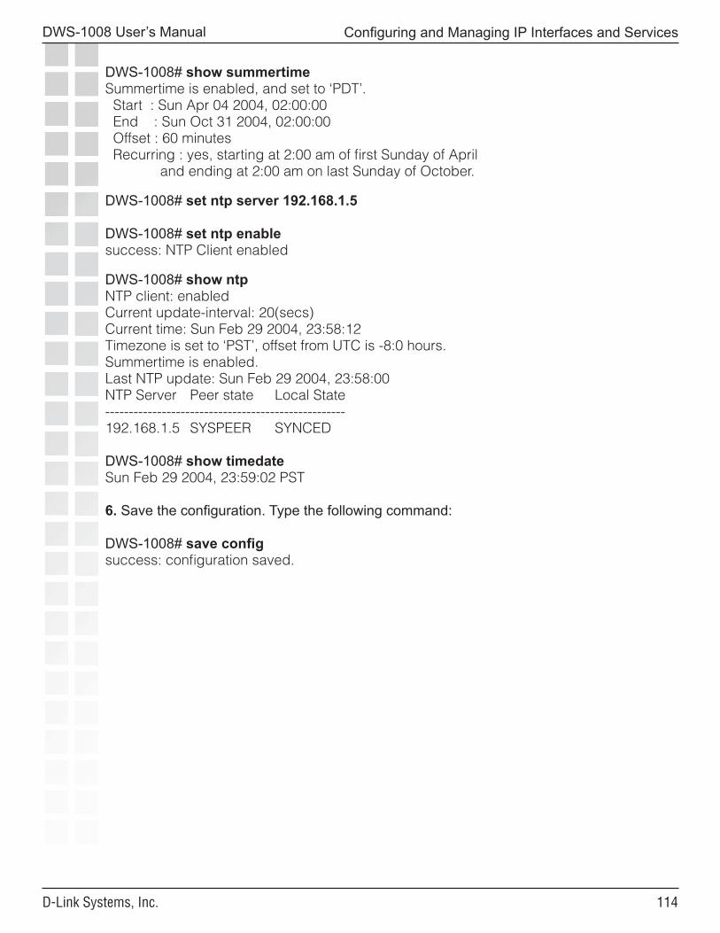
���
DWS-1008 User’s Manual
D-Link Systems, Inc.
Configuring and Managing IP Interfaces and Services
DWS-1008# show summertimeSummertime is enabled, and set to ‘PDT’. Start : Sun Apr 04 2004, 02:00:00 End : Sun Oct 31 2004, 02:00:00 Offset : 60 minutes Recurring : yes, starting at 2:00 am of first Sunday of April and ending at 2:00 am on last Sunday of October.
DWS-1008# set ntp server 192.168.1.5
DWS-1008# set ntp enablesuccess: NTP Client enabled
DWS-1008# show ntpNTP client: enabledCurrent update-interval: 20(secs)Current time: Sun Feb 29 2004, 23:58:12Timezone is set to ‘PST’, offset from UTC is -8:0 hours.Summertime is enabled.Last NTP update: Sun Feb 29 2004, 23:58:00NTP Server Peer state Local State---------------------------------------------------192.168.1.5 SYSPEER SYNCED
DWS-1008# show timedateSun Feb 29 2004, 23:59:02 PST
6. Save the configuration. Type the following command:
DWS-1008# save configsuccess: configuration saved.
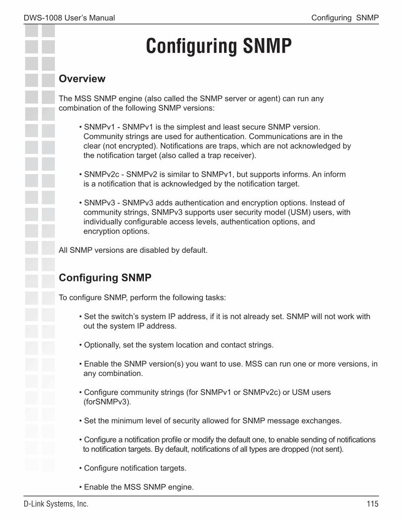
���
DWS-1008 User’s Manual
D-Link Systems, Inc.
Configuring SNMP
Configuring SNMPOverview
The MSS SNMP engine (also called the SNMP server or agent) can run anycombination of the following SNMP versions:
• SNMPv1 - SNMPv1 is the simplest and least secure SNMP version. Community strings are used for authentication. Communications are in the clear (not encrypted). Notifications are traps, which are not acknowledged by the notification target (also called a trap receiver).
• SNMPv2c - SNMPv2 is similar to SNMPv1, but supports informs. An inform is a notification that is acknowledged by the notification target.
• SNMPv3 - SNMPv3 adds authentication and encryption options. Instead of community strings, SNMPv3 supports user security model (USM) users, with individually configurable access levels, authentication options, and encryption options.
All SNMP versions are disabled by default.
Configuring SNMP
To configure SNMP, perform the following tasks:
• Set the switch’s system IP address, if it is not already set. SNMP will not work with out the system IP address.
• Optionally, set the system location and contact strings.
• Enable the SNMP version(s) you want to use. MSS can run one or more versions, in any combination.
• Configure community strings (for SNMPv1 or SNMPv2c) or USM users (forSNMPv3).
• Set the minimum level of security allowed for SNMP message exchanges.
• Configure a notification profile or modify the default one, to enable sending of notifications to notification targets. By default, notifications of all types are dropped (not sent).
• Configure notification targets.
• Enable the MSS SNMP engine.
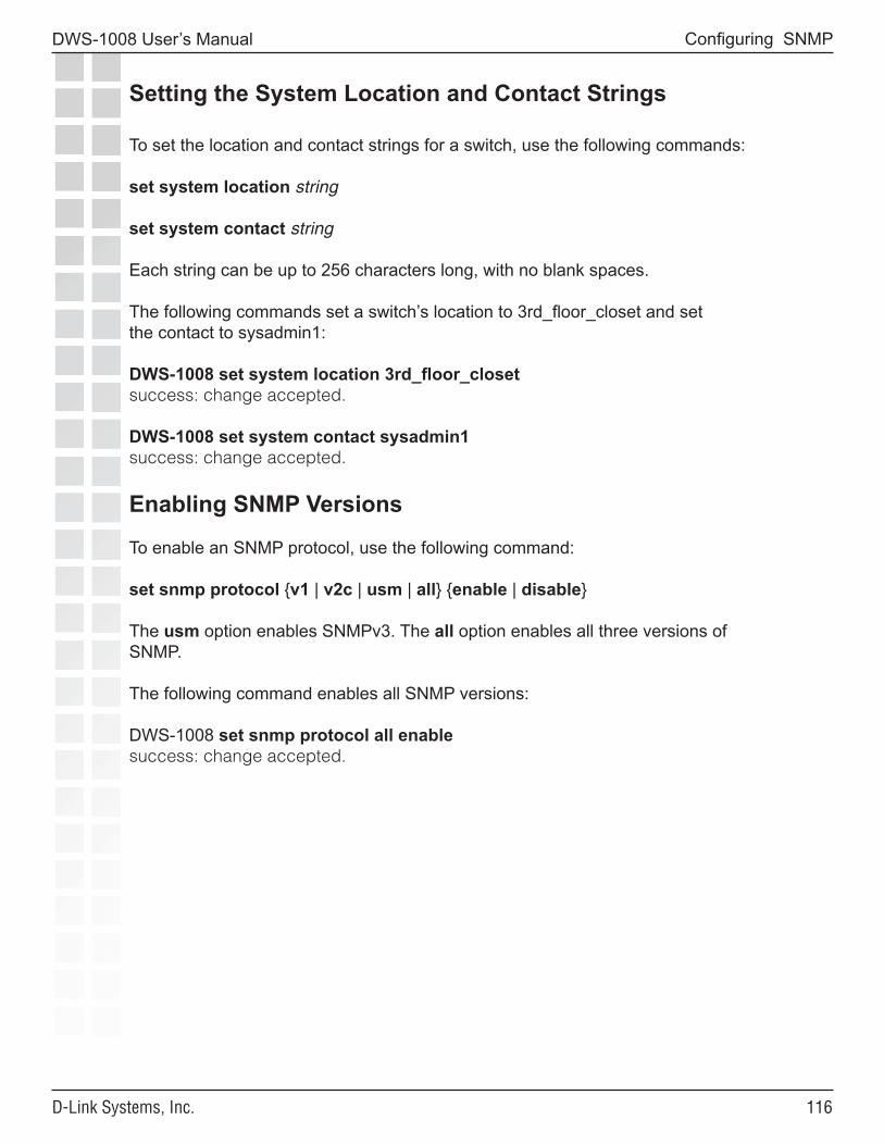
���
DWS-1008 User’s Manual
D-Link Systems, Inc.
Configuring SNMP
Setting the System Location and Contact Strings
To set the location and contact strings for a switch, use the following commands:
set system location string
set system contact string
Each string can be up to 256 characters long, with no blank spaces.
The following commands set a switch’s location to 3rd_floor_closet and setthe contact to sysadmin1:
DWS-1008 set system location 3rd_floor_closetsuccess: change accepted.
DWS-1008 set system contact sysadmin1success: change accepted.
Enabling SNMP Versions
To enable an SNMP protocol, use the following command:
set snmp protocol {v1 | v2c | usm | all} {enable | disable}
The usm option enables SNMPv3. The all option enables all three versions ofSNMP.
The following command enables all SNMP versions:
DWS-1008 set snmp protocol all enablesuccess: change accepted.
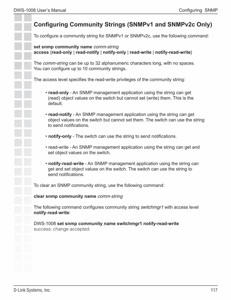
���
DWS-1008 User’s Manual
D-Link Systems, Inc.
Configuring SNMP
Configuring Community Strings (SNMPv1 and SNMPv2c Only)
To configure a community string for SNMPv1 or SNMPv2c, use the following command:
set snmp community name comm-stringaccess {read-only | read-notify | notify-only | read-write | notify-read-write}
The comm-string can be up to 32 alphanumeric characters long, with no spaces.You can configure up to 10 community strings.
The access level specifies the read-write privileges of the community string:
• read-only - An SNMP management application using the string can get (read) object values on the switch but cannot set (write) them. This is the default.
• read-notify - An SNMP management application using the string can get object values on the switch but cannot set them. The switch can use the string to send notifications.
• notify-only - The switch can use the string to send notifications.
• read-write - An SNMP management application using the string can get and set object values on the switch.
• notify-read-write - An SNMP management application using the string can get and set object values on the switch. The switch can use the string to send notifications.
To clear an SNMP community string, use the following command:
clear snmp community name comm-string
The following command configures community string switchmgr1 with access level notify-read-write:
DWS-1008 set snmp community name switchmgr1 notify-read-writesuccess: change accepted.
���
DWS-1008 User’s Manual
D-Link Systems, Inc.
Configuring SNMP
Creating a USM User for SNMPv3
To create a USM user for SNMPv3, use the following command:
set snmp usm usm-username snmp-engine-id {ip ip-addr | local | hex hex-string} access {read-only | read-notify | notify-only | read-write | notify-read-write} auth-type {none | md5 | sha} {auth-pass-phrase string | auth-key hex-string} encrypt-type {none | des | 3des | aes} {encrypt-pass-phrase string | encrypt-key hex-string}
To clear a USM user, use the following command:
clear snmp usm usm-username
The usm-username can be up to 32 alphanumeric characters long, with no spaces.You can configure up to 10 SNMPv3 users.
The snmp-engine-id option specifies a unique identifier for an instance of an SNMP engine. To send informs, you must specify the engine ID of the inform receiver. To send traps and to allow get and set operations and so on, specify local as the engine ID.
• hex hex-string - ID is a hexadecimal string.
• ip ip-addr - ID is based on the IP address of the station running the management application. Enter the IP address of the station. MSS calculates the engine ID based on the address.
• local - Uses the value computed from the switch’s system IP address.
The access option specifies the access level of the user. The options are the same as the access options for community strings.
���
DWS-1008 User’s Manual
D-Link Systems, Inc.
Configuring SNMP
The auth-type option specifies the authentication type used to authenticate communications with the remote SNMP engine. You can specify one of the following:
• none - No authentication is used. This is the default. • md5 - Message-digest algorithm 5 is used. • sha - Secure Hashing Algorithm (SHA) is used.
If the authentication type is md5 or sha, you can specify a passphrase or ahexadecimal key.
• To specify a passphrase, use the auth-pass-phrase string option. The string can be from 8 to 32 alphanumeric characters long, with no spaces. • To specify a key, use the auth-key hex-string option.
The encrypt-type option specifies the encryption type used for SNMP traffic. Youcan specify one of the following:
• none - No encryption is used. This is the default. • des - Data Encryption Standard (DES) encryption is used. • 3des - Triple DES encryption is used. • aes - Advanced Encryption Standard (AES) encryption is used.
If the encryption type is des, 3des, or aes, you can specify a passphrase or a hexadecimal key.
• To specify a passphrase, use the encrypt-pass-phrase string option. The string can be from 8 to 32 alphanumeric characters long, with no spaces. • To specify a key, use the encrypt-key hex-string option.
Command Examples
The following command creates USM user snmpmgr1, associated with the localSNMP engine ID. This user can send traps to notification receivers.
DWS-1008 set snmp usm snmpmgr1 snmp-engine-id localsuccess: change accepted.
The following command creates USM user securesnmpmgr1, which uses SHAauthentication and 3DES encryption with passphrases. This user can send informsto the notification receiver that has engine ID 192.168.40.2.
DWS-1008 set snmp usm securesnmpmgr1 snmp-engine-id ip 192.168.40.2 auth-type sha auth-pass-phrase myauthpword encrypt-type 3des encrypt-pass-phrase mycryptpwordsuccess: change accepted.
��0
DWS-1008 User’s Manual
D-Link Systems, Inc.
Configuring SNMP
Setting SNMP Security
By default, MSS allows nonsecure SNMP message exchanges. You can configureMSS to require secure SNMP exchanges instead.
Depending on the level of security you want MSS to enforce, you can requireauthentication of message exchanges only, or of message exchanges andnotifications. You also can require encryption in addition to authentication.
SNMPv1 and SNMPv2c do not support authentication or encryption. If you planto use SNMPv1 or SNMPv2c, leave the minimum level of SNMP security set tounsecured.
To set the minimum level of security MSS requires for SNMP, use the followingcommand:
set snmp security {unsecured | authenticated | encrypted | auth-req-unsec-notify}
You can specify one of the following options:
• unsecured - SNMP message exchanges are not secure. This is the default, and is the only value supported for SNMPv1 and SNMPv2c. (This security level is the same as the noAuthNoPriv level described in SNMPv3 RFCs.) • authenticated - SNMP message exchanges are authenticated but are not encrypted. (This security level is the same as the authNoPriv level described in SNMPv3 RFCs.) • encrypted - SNMP message exchanges are authenticated and encrypted. (This security level is the same as the authPriv level described in SNMPv3 RFCs.)
• auth-req-unsec-notify - SNMP message exchanges are authenticated but are not encrypted, and notifications are neither authenticated nor encrypted.
Command ExampleThe following command sets the minimum level of SNMP security allowed toauthentication and encryption:
DWS-1008 set snmp security encryptedsuccess: change accepted.
���
DWS-1008 User’s Manual
D-Link Systems, Inc.
Configuring SNMP
Configuring a Notification ProfileA notification profile is a named list of all the notification types that can be generated by a switch, and for each notification type, the action to take (drop or send) when an event occurs.
A default notification profile (named default) is already configured in MSS. All notifications in the default profile are dropped by default. You can configure up to 10 notification profiles.
To modify the default notification profile or create a new one, use the following command:
set snmp profile {default | profile-name} {drop | send}{notification-type | all}
To clear a notification profile, use the following command:
clear snmp profile profile-name
The profile-name can be up to 32 alphanumeric characters long, with no spaces.To modify the default notification profile, specify default.
The notification-type can be one of the following:
• AuthenTraps - Generated when the DWS-1008 switch’s SNMP engine receives a bad community string.
• AutoTuneRadioChannelChangeTraps - Generated when the RF Auto-Tuning feature changes the channel on a radio.
• AutoTuneRadioPowerChangeTraps - Generated when the RF Auto-Tuning feature changes the power setting on a radio.
• ClientAssociationFailureTraps - Generated when a client’s attempt to associate with a radio fails.
• ClientAuthorizationSuccessTraps - Generated when a client is successfully authorized.
• ClientAuthenticationFailureTraps - Generated when authentication fails for a client.
• ClientAuthorizationFailureTraps - Generated when authorization fails for a client.
• ClientClearedTraps - Generated when a client’s session is cleared.
• ClientDeAssociationTraps - Generated when a client is dissociated from a radio.
���
DWS-1008 User’s Manual
D-Link Systems, Inc.
Configuring SNMP
• ClientDot1xFailureTraps - Generated when a client experiences an 802.1X failure.
• ClientRoamingTraps - Generated when a client roams.
• CounterMeasureStartTraps - Generated when MSS begins countermeasures against a rogue access point.
• CounterMeasureStopTraps - Generated when MSS stops countermeasures against a rogue access point.
• DAPConnectWarningTraps - generated when a Distributed AP whose fingerprint has not been configured in MSS establishes a management session with the switch.
• DeviceFailTraps - Generated when an event with an Alert severity occurs.
• DeviceOkayTraps - Generated when a device returns to its normal state.
• LinkDownTraps - Generated when the link is lost on a port.
• LinkUpTraps - Generated when the link is detected on a port.
• MichaelMICFailureTraps - Generated when two Michael message integrity code (MIC) failures occur within 60 seconds, triggering Wi-Fi Protected Access (WPA) countermeasures.
• MP BootTraps - Generated when a DWL-8220AP boots.
• MP TimeoutTraps - Generated when an access point fails to respond to the DWS-1008 switch.
• PoEFailTraps - Generated when a serious PoE problem, such as a short circuit, occurs.
• RFDetectAdhocUserTraps - Generated when MSS detects an ad-hoc user.
• RFDetectRogueAPTraps - Generated when MS detects a rogue access point.
• RFDetectRogueDisappearTraps - Generated when a rogue access point is no longer being detected.
���
DWS-1008 User’s Manual
D-Link Systems, Inc.
Configuring SNMP
• RFDetectClientViaRogueWiredAPTraps - Generated when MSS detects, on the wired part of the network, the MAC address of a wireless client associated with a third-party AP.
• RFDetectDoSPortTraps - Generated when MSS detects an associate request flood, reassociate request flood, or disassociate request flood.
• RFDetectDoSTraps - Generated when MSS detects a DoS attack other than an associate request flood, reassociate request flood, or disassociate request flood.
• RFDetectInterferingRogueAPTraps - Generated when an interfering device is detected.
• RFDetectInterferingRogueDisappearTraps - Generated when an interfering device is no longer detected.
• RFDetectSpoofedMacAPTraps - Generated when MSS detects a wireless packet with the source MAC address of a D-Link AP, but without the spoofed AP’s signature (fingerprint).
• RFDetectSpoofedSsidAPTraps - Generated when MSS detects beacon rames for a valid SSID, but sent by a rogue AP.
• RFDetectUnAuthorizedAPTraps - Generated when MSS detects the MAC address of an AP that is on the attack list.
• RFDetectUnAuthorizedOuiTraps - Generated when a wireless device that is not on the list of permitted vendors is detected.
• RFDetectUnAuthorizedSsidTraps - Generated when an SSID that is not on the permitted SSID list is detected.
To apply the configuration change to all notification types, specify all.
The drop or send option specifies the action that the SNMP engine takes with regard to notifications.

���
DWS-1008 User’s Manual
D-Link Systems, Inc.
Configuring SNMP
Command Examples
The following command changes the action in the default notification profile from drop to send for all notification types:
DWS-1008 set snmp notify profile default send allsuccess: change accepted.
The following commands create notification profile snmpprof_rfdetect, and change the action to send for all RF detection notification types:
DWS-1008 set snmp notify profile snmpprof_rfdetect sendRFDetectAdhocUserTrapssuccess: change accepted.
DWS-1008 set snmp notify profile snmpprof_rfdetect sendRFDetectClientViaRogueWiredAPTrapssuccess: change accepted.
DWS-1008 set snmp notify profile snmpprof_rfdetect send RFDetectDoSTrapssuccess: change accepted.
DWS-1008 set snmp notify profile snmpprof_rfdetect sendRFDetectAdhocUserTrapssuccess: change accepted.
DWS-1008 set snmp notify profile snmpprof_rfdetect sendRFDetectInterferingRogueAPTrapssuccess: change accepted.
DWS-1008 set snmp notify profile snmpprof_rfdetect sendRFDetectInterferingRogueDisappearTrapssuccess: change accepted.
DWS-1008 set snmp notify profile snmpprof_rfdetect sendRFDetectRogueAPTrapssuccess: change accepted.
DWS-1008 set snmp notify profile snmpprof_rfdetect sendRFDetectRogueDisappearTrapssuccess: change accepted.
DWS-1008 set snmp notify profile snmpprof_rfdetect sendRFDetectSpoofedMacAPTrapssuccess: change accepted.
���
DWS-1008 User’s Manual
D-Link Systems, Inc.
Configuring SNMP
DWS-1008 set snmp notify profile snmpprof_rfdetect sendRFDetectSpoofedSsidAPTrapssuccess: change accepted.
DWS-1008 set snmp notify profile snmpprof_rfdetect sendRFDetectUnAuthorizedAPTrapssuccess: change accepted.
DWS-1008 set snmp notify profile snmpprof_rfdetect sendRFDetectUnAuthorizedOuiTrapssuccess: change accepted.
DWS-1008 set snmp notify profile snmpprof_rfdetect sendRFDetectUnAuthorizedSsidTrapssuccess: change accepted.
Configuring a Notification Target
A notification target is a remote device to which MSS sends SNMP notifications.
You can configure the MSS SNMP engine to send confirmed notifications (informs) or unconfirmed notifications (traps). Some of the command options differ depending on the SNMP version and the type of notification you specify. You can configure up to 10 notification targets.
To configure a notification target for informs from SNMPv3, use the following command:
set snmp notify target target-num ip-addr[:udp-port-number]usm inform user usernamesnmp-engine-id {ip | hex hex-string}[profile profile-name][security {unsecured | authenticated | encrypted}][retries num][timeout num]
To configure a notification target for traps from SNMPv3, use the following command:
set snmp notify target target-num ip-addr[:udp-port-number]usm trap user username[profile profile-name][security {unsecured | authenticated | encrypted}]
���
DWS-1008 User’s Manual
D-Link Systems, Inc.
Configuring SNMP
To configure a notification target for informs from SNMPv2c, use the following command:
set snmp notify target target-num ip-addr[:udp-port-number]v2c community-string inform[profile profile-name][retries num][timeout num]
To configure a notification target for traps from SNMPv2c, use the following command:
set snmp notify target target-num ip-addr[:udp-port-number]v2c community-string trap[profile profile-name]
To configure a notification target for traps from SNMPv1, use the following command:
set snmp notify target target-num ip-addr[:udp-port-number]v1 community-string[profile profile-name]
To clear a notification target, use the following command:
clear snmp notify target target-num
The target-num is an ID for the target. This ID is local to the DWS-1008 switch and does not need to correspond to a value on the target itself. You can specify a number from 1 to 10.
The ip-addr[:udp-port-number] is the IP address of the server. You also can specify the UDP port number to send notifications to. The default is 162.
Use v1, v2c, or usm to specify the SNMP version.
The inform or trap option specifies whether the MSS SNMP engine expects the target to acknowledge notifications sent to the target by the DWS-1008 switch. Use inform if you want acknowledgements. Use trap if you do not want acknowledgements. The inform option is applicable to SNMP version v2c or usm only.
The username is a USM username, and is applicable only when the SNMP version is usm. If the user will send informs rather than traps, you also must specify the snmp-engine-id of the target. Specify ip if the target’s SNMP engine ID is based on its IP address. If the target’s SNMP engine ID is a hexadecimal value, use hex hex-string to specify the value.
The community-string is applicable only when the SNMP version is v1 or v2c.
The profile-name is the notification profile. The default is default.
���
DWS-1008 User’s Manual
D-Link Systems, Inc.
Configuring SNMP
The security option specifies the security level, and is applicable only when the SNMP version is usm:
• unsecured - Message exchanges are not authenticated, nor are they encrypted. This is the default.
• authenticated - Message exchanges are authenticated, but are not encrypted.
• encrypted - Message exchanges are authenticated and encrypted.
The retries and timeout options are applicable only when the SNMP version is v2c or usm and the notification type is inform. The retries option specifies the number of times the MSS SNMP engine will resend a notification that has not been acknowledged by the target. You can specify from 0 to 3 retries. The default is 0. The timeout option specifies the number of seconds MSS waits for acknowledgement of a notification. You can specify from 1 to 5 seconds. The default is 2.
Command Examples
The following command configures a notification target for acknowledgednotifications:
DWS-1008 set snmp notify target 1 10.10.40.9 usm inform user securesnmpmgr1snmp-engine-id ipsuccess: change accepted.
This command configures target 1 at IP address 10.10.40.9. The target’s SNMP engine ID is based on its address. The MSS SNMP engine will send notifications based on the default profile, and will require the target to acknowledge receiving them.
The following command configures a notification target for unacknowledged notifications:
DWS-1008 set snmp notify target 2 10.10.40.10 v1 trapsuccess: change accepted.
Enabling the SNMP Service
To enable the MSS SNMP service, use the following command:
set ip snmp server {enable | disable}
The following command enables the SNMP service:
DWS-1008 set ip snmp server enablesuccess: change accepted.
���
DWS-1008 User’s Manual
D-Link Systems, Inc.
Configuring SNMP
Displaying SNMP Information
You can display the following SNMP information:
• Version and status information • Configured community strings • User-based security model (USM) settings • Notification targets • SNMP statistics counters
Displaying SNMP Version and Status Information
To display SNMP version and status information, use the following command:
DWS-1008 show snmp status
Displaying the Configured SNMP Community Strings
To display the configured SNMP community strings, use the following command:
DWS-1008 show snmp community
Displaying USM Settings
To display USM settings, use the following command:
DWS-1008 show snmp usm
Displaying Notification Profiles
To display notification profiles, use the following command:
DWS-1008 show snmp notify profile
The command lists settings separately for each notification profile. The use count indicates how many notification targets use the profile. For each notification type, the command lists whether MSS sends notifications of that type to the targets that use the notification profile.
Displaying Notification Targets
To display a list of the SNMP notification targets, use the following command:
DWS-1008 show snmp notify target

���
DWS-1008 User’s Manual
D-Link Systems, Inc.
Configuring SNMP
Displaying SNMP Statistics Counters
To display SNMP statistics counters, use the following command:
DWS-1008 show snmp counters
��0
DWS-1008 User’s Manual
D-Link Systems, Inc.
Configuring DWL-8220AP Access Points
Configuring DWL-8220AP Access PointsDWL-8220AP access points contain radios that provide networking between your wired network and IEEE 802.11 wireless users. A DWL-8220AP access point connects to the wired network through a 10/100 Ethernet link and connects to wireless users through radio signals.
DWL-8220AP Overview A DWL-8220AP can be directly connected to a switch port or indirectly connected to a switch through a Layer 2 or IPv4 Layer 3 network. For redundancy, a DWL-8220AP can have one of the following combinations of multiple connections:
• Two direct connections to a single switch or two switches.
• Up to four indirect connections to switches through intermediate Layer 2 or Layer 3 networks.
• One direct connection to a switch and up to three indirect connections to switches through intermediate Layer 2 or Layer 3 networks.
To configure DWL-8220AP access points, perform the following tasks, in this order:
• Specify the country of operation.
• Configure DWL-8220AP access ports, Distributed AP connections, and dual homing.
• If required, configure radio-specific parameters, which include the channel number, transmit power, and external antenna model.
Note: You do not need to set channels and power if you use RF Auto-Tuning to set these values. You do not need to specify an external antenna model unless a radio uses an external antenna.
• Configure SSID and encryption settings in a service profile.
• Map the service profile to a radio profile, assign the radio profile to radios, and enable the radios.
Country of Operation
Before you can configure DWL-8220AP access points and radio parameters, you must specify the country in which you plan to operate the radios. Since each country has different regulatory environments, the country code determines the transmit power levels and channels you can configure on the radios. MSS ensures that the values you can configure are valid for the country you specify.
���
DWS-1008 User’s Manual
D-Link Systems, Inc.
Configuring DWL-8220AP Access Points
Directly Connected DWL-8220APs and Distributed APs
To configure the switch to support a DWL-8220AP access point, you must first determine how the DWL-8220AP will connect to the switch. There are two types of AP to DWS-1008 connection: direct and distributed.
• In direct connection, a DWL-8220AP connects to one or two 10/100 ports on a DWS-1008. The DWS-1008 port is then configured specifically for a direct attachment to a DWL-8220AP. There is no intermediate networking equipment between the switch and AP and only one AP is connected to the switch port. The switch’s 10/100 port provides PoE to the AP. The DWS-1008 also forwards data only to and from the configured AP on that port. The port numbers on the switch configured for directly attached MPs reference a particular AP.
• A DWL-8220AP that is not directly connected to a DWS-1008 is considered a Distributed AP. There may be intermediate Layer 2 switches or Layer 3 IP routers between the DWS-1008 and AP. The DWS-1008 may communicate to the Distributed AP through any network port. (A network port is any port connecting the switch to other networking devices, such as switches and routers, and it can also be configured for 802.1Q VLAN tagging.) The DWS-1008 contains a configuration for a Distributed AP based on the AP’s serial number. Similar to ports configured for directly connected APs, Distributed AP configurations are numbered and can reference a particular AP. These numbered configurations do not, however, reference any physical port.
Distributed AP Network Requirements
Because Distributed APs are not directly attached to an DWS-1008, they require additional support from the network in order to function.
• Power - PoE must be provided on one of the Ethernet connections to the AP. Be sure to use a PoE injection device that has been tested by D-Link. Providing PoE on both of the Ethernet connections (on models that have two Ethernet ports) allows redundant PoE.
• DHCP - A Distributed AP uses TCP/IP for communication, and relies on DHCP to obtain IP parameters. Therefore, DHCP services must be available on the subnet that the AP is connected to. DHCP must provide the following parameters to the AP:
• IP address• DNS server address• Gateway address
• DNS - If the intermediate network between the switch and Distributed AP includes one or more IP routers, create a TRPZ.mynetwork.com or wlan-switch.mynetwork.com entry on the DNS server. The entry needs to map one of these names to the system IP address of the switch.
The DNS entry allows the AP to communicate with an switch that is not on the AP’s
���
DWS-1008 User’s Manual
D-Link Systems, Inc.
Configuring DWL-8220AP Access Points
subnet. If the AP is unable to locate an DWS-1008 on the subnet it is connected to, the AP sends DNS requests to both TRPZ and wlan-switch, where the DNS suffix for mynetwork.com is learned through DHCP.
• If only TRPZ is defined in DNS, the AP contacts the switch whose IP address is returned for TRPZ.
• If only wlan-switch is defined in DNS, the AP contacts the switch whose IP address is returned for wlan-switch.
• If both TRPZ and wlan-switch are defined in DNS, the AP contacts the switch whose IP address is returned for TRPZ. The AP ignores the IP address returned for wlan-switch.
• If both TRPZ and wlan-switch are defined in DNS, and the AP is unable to contact the IP address returned for TRPZ, the AP never contacts the IP address returned for wlan-switch. The AP does not boot.
Distributed APs and STP
A Distributed AP is a leaf device. You do not need to enable STP on the port that is directly connected to the AP.
If Spanning Tree Protocol (STP) is enabled on the port that is directly connected to a Distributed AP, you might need to change the STP configuration on the port, to allow the AP to boot.
Note: STP on a port directly connected to a Distributed AP can prevent the AP from booting.
As part of the boot process, a DWL-8220AP disables and reenables the link on the port over which the AP is attempting to boot. If STP is enabled on the device that is directly connected to the port, the link state change can cause the port on the other device to leave the forwarding state and stop forwarding traffic. The port remains unable to forward traffic for the duration of the STP forwarding delay.
A DWL-8220AP waits 30 seconds to receive a reply to its DHCP Discover message, then tries to boot using the other AP port. If the boot attempt fails on the other port also, the AP then reattempts to boot on the first port. The process continues until a boot attempt is successful. If STP prevents the other device’s port from forwarding traffic during each boot attempt, the AP repeatedly disables and reenables the link, causing STP to repeatedly stop the other device’s port from forwarding traffic. As a result, the boot attempt is never successful.
To allow a DWL-8220AP to boot over a link that has STP enabled, do one of the following
���
DWS-1008 User’s Manual
D-Link Systems, Inc.
Configuring DWL-8220AP Access Points
on the other device:
• Disable STP on the other device’s port.
• Enable the port fast convergence feature, if supported, on the other device’s port. (On some vendors’ devices, this feature is called PortFast.)
• If the other device is running Rapid Spanning Tree or Multiple Spanning Tree, set the port into edge port mode.
Distributed APs and DHCP Option 43
The DHCP option 43 field provides a simple and effective way for APs to find switches across an intermediate Layer 3 network, and is especially useful in networks that are geographically distributed or have a flat domain name space. You can use the DHCP option 43 field to provide a list of DWS-1008 IP addresses, without the need to configure DNS servers.
To use DHCP option 43, configure the option to contain a comma-separated list of DWS-1008 IP addresses or hostnames, in the following format:
ip:ip-addr1,ip-addr2,...
or
host:hostname1,hostname2,...
You can use an IP address list or a hostname list, but not both. If the list contains both types of values, the AP does not attempt to use the list.
The ip and host keywords can be in lowercase, uppercase (IP or HOST), or mixed case (example: Ip, Host, and so on.) You can use spaces after the colon or commas, but spaces are not supported within IP addresses or hostnames. Leading zeroes are supported in IP addresses. For example, 100.130.001.1 is valid.
Valid characters in hostnames are uppercase and lowercase letters, numbers, periods ( . ), and hyphens ( - ). Other characters are not supported.
If you use the host option, you must configure the network’s DNS server with address records that map the hostnames in the list to the DWS-1008 IP addresses.
After receiving a DHCP ACK containing a valid string for option 43, a Distributed AP sends a unicast message to the each switch in the list, to request a software image and configuration. If the AP does not receive a reply to the request after one minute, the AP starts the boot process over with a new DHCP Discover message, this time from AP port 2. No configuration is required on the switch itself.
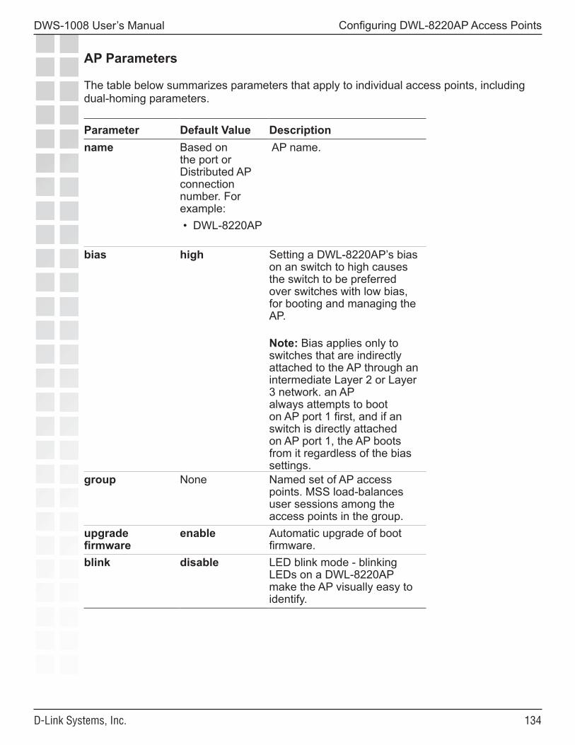
���
DWS-1008 User’s Manual
D-Link Systems, Inc.
Configuring DWL-8220AP Access Points
AP Parameters
The table below summarizes parameters that apply to individual access points, including dual-homing parameters.
Parameter Default Value Descriptionname Based on
the port or Distributed AP connection number. For example: • DWL-8220AP
AP name.
bias high Setting a DWL-8220AP’s bias on an switch to high causes the switch to be preferred over switches with low bias, for booting and managing the AP.
Note: Bias applies only to switches that are indirectly attached to the AP through an intermediate Layer 2 or Layer 3 network. an AP always attempts to boot on AP port 1 first, and if an switch is directly attached on AP port 1, the AP boots from it regardless of the bias settings.
group None Named set of AP access points. MSS load-balances user sessions among the access points in the group.
upgrade firmware
enable Automatic upgrade of boot firmware.
blink disable LED blink mode - blinking LEDs on a DWL-8220AP make the AP visually easy to identify.
���
DWS-1008 User’s Manual
D-Link Systems, Inc.
Configuring DWL-8220AP Access Points
Resiliency and Dual-Homing Options for APs
APs can support a wide variety of resiliency options. Redundancy for PoE, for data link connections and for DWS-1008 services can be provided to the AP.
• PoE redundancy - On AP models that have two Ethernet ports, you can provide PoE redundancy by connecting both ports to PoE sources. PoE can come from a directly connected DWS-1008 or a PoE injector. Dual-homing support for PoE is automatically enabled when you connect both AP Ethernet ports.
• Data link redundancy - You can provide data link redundancy by connecting both Ethernet ports directly to one DWS-1008, two switches, an intermediate Ethernet switch, or a combination of DWS-1008 and Ethernet switch. If an intermediate Ethernet connection is used, you also need a Distributed AP configuration on an DWS-1008 somewhere in the network. Dual-homing support for data link redundancy is automatically enabled when you connect both AP Ethernet ports.
• DWS-1008 redundancy - You can provide redundancy of DWS-1008 services by dual-homing the AP to two directly connected switches; or by configuring a Distributed AP configuration either on two or more indirectly connected switches, or on a combination of a directly connected DWS-1008 and one or more indirectly connected switches. To provide DWS-1008 redundancy on a DWL-8220AP model that has only one AP port, configure a Distributed AP connection on two or more indirectly connected switches.
Bias
On an switch, configurations for APs have a bias (low or high) associated with them. The default is high. A switch with high bias for a DWL-8220AP is preferred over an DWS-1008 with low bias for the AP.
If more than one switch has high bias, or the bias for all connections is the same, the switch that has the greatest capacity to add more active APs is preferred. For example, if one switch has 50 active APs while another switch has 60 active APs, and both switches are capable of managing 80 active APs, the new AP uses the switch that has only 50 active APs.
Note: Bias applies only to switches that are indirectly attached to the AP through an intermediate Layer 2 or Layer 3 network. An AP always attempts to boot on AP port 1 first, and if a switch is directly attached on AP port 1, the AP boots from it regardless of the bias settings.
���
DWS-1008 User’s Manual
D-Link Systems, Inc.
Configuring DWL-8220AP Access Points
AP Boot Process
A DWL-8220AP access point brings up the link on the AP’s port 1 and attempts the boot process outlined below.
If you want the AP to boot from a specific DWS-1008, you must ensure that only one DWS-1008 can respond through the AP’s port 1 with a high bias under normal operation. If the boot process fails to locate any DWS-1008, the AP then attempts the boot process on the AP’s port 2.
Note: The steps below describe the network behavior of a Distributed AP when booting. These steps do not apply to a directly connected AP. The boot process for a directly connected AP occurs strictly between the AP and switch and makes no use of the network’s DHCP or DNS services.
1. The AP sends a DHCP Discover message from the AP’s port 1 to the broadcast address.
2. If a DHCP server is present on the subnet or through a router configured to relay DHCP, the server replies with a unicast DHCP Offer message. The Offer message must contain the following parameters:
• IP address for the AP• IP address of the network’s DNS server• IP address of the subnet’s default gateway
Optionally, the Offer message can also contain a list of DWS-1008 IP addresses or hostnames, in the option 43 field of the DHCP message.
Continuing the DHCP process, the AP broadcasts a DHCP Request to the DHCP servers, and receives an ACK from a DHCP server. The AP then configures its network connection with the information contained in the ACK message from that server.
3. The AP sends a Find DWS-1008 message to UDP port 5000 on the subnet broadcast address.
• The switch that is in the same IP subnet as the AP will receive the message and respond with a Find DWS-1008 Reply message.
• If the AP is configured as a Distributed AP on a switch and the connection bias is high, the switch immediately sends a Find DWS-1008 Reply message.
• If the AP is configured as a Distributed AP on a switch but the connection bias is low, that switch waits one second, then sends a Find DWS-1008 Reply message. The delay allows switches with high bias for the AP to respond first.
���
DWS-1008 User’s Manual
D-Link Systems, Inc.
Configuring DWL-8220AP Access Points
• If an switch that receives the Find DWS-1008 message does not have the Distributed AP in its configuration but another switch in the same MobileLAN does, the switch waits two seconds, then sends a Find DWS-1008 Reply message with the IP address of the best switch to use. The determination of best switch is based on the bias settings for the AP on each switch and on the capacity of each switch to add new active AP connections.
The process skips to step 10.
• If no switches reply, the AP resends the Find DWS-1008 broadcast up to 11 more times. If no DWS-1008s reply after all 12 attempts, the AP attempts to find a DWS-1008 based on DHCP option 43 values received in the DHCP ACK. The process continues with step 4.
4. This step applies only if the DHCP ACK contained DWS-1008 IP addresses or hostnames in the option 43 field. If the ACK did not contain DWS-1008 IP addresses or hostnames in the option 43 field, skip to step 5.
If the DHCP ACK message contained a list of DWS-1008 IP addresses or hostnames in the DHCP option 43 field, the AP contacts the switches:
• If the DHCP ACK message contained a list of DWS-1008 IP addresses, in DHCP option 43, the AP sends a unicast Find DWS-1008 message to each address. The process continues with step 8.
• If the DHCP ACK message contained a list of DWS-1008 hostnames in DHCP option 43, the AP sends DNS Requests to the DNS server for the IP addresses of the switches, then sends a unicast Find DWS-1008 message to each address. The process continues with step 8.
Note: This method requires DNS address records on the DNS server that map the hostnames to the switch IP addresses.
If no switches reply, the AP resends the Find DWS-1008 messages up to 11 more times. If no DWS-1008s reply after all 12 attempts, the AP tries to find a switch using the DNS server. The process continues with step 5.
5. If the AP is unable to locate an DWS-1008 on the subnet it is connected to, and is unable to find an DWS-1008 based on DHCP option 43, the AP sends DNS requests to both TRPZ and wlan-switch, where the DNS suffix for mynetwork.com is learned through DHCP.
Note: You must configure a DNS address record on your DNS server for the switch IP address. Otherwise, the DNS server cannot provide the switch’s address to the AP.
���
DWS-1008 User’s Manual
D-Link Systems, Inc.
Configuring DWL-8220AP Access Points
6. The DNS server replies with the system IP address of an switch.
• If only TRPZ is defined in DNS, the AP sends a unicast Find DWS-1008 message to the switch whose IP address is returned for TRPZ.
• If only wlan-switch is defined in DNS, the AP sends a unicast Find DWS-1008 message to the switch whose IP address is returned for wlan-switch.
• If both TRPZ and wlan-switch are defined in DNS, the AP sends a unicast Find DWS-1008 message to the switch whose IP address is returned for TRPZ. The AP ignores the IP address returned for wlan-switch.
• If both TRPZ and wlan-switch are defined in DNS, and the AP is unable to contact the IP address returned for TRPZ, the AP never contacts the IP address returned for wlan-switch. The AP does not boot.
7. The AP sends Find DWS-1008 requests to the DWS-1008 IP addresses given by the DNS reply. If a DWS-1008 receives the Find DWS-1008 Request, the process continues with step 8.
However, if no switches reply, the AP retries this method up to 11 more times:
• If the DWS-1008 replies after all 12 attempts, the AP begins the process again with step 1 on the other AP port.
• If the other AP port does not have a link or the AP has only one port, the AP instead restarts, and begins the process again with step 1 on the same AP port.
8. The DWS-1008 that receives the Find DWS-1008 request determines the best DWS-1008 for the AP to use, based on the bias settings for the AP on each switch. If more than one switch has high bias for the AP or all switches have the same bias, the DWS-1008 suggests the switch that has the highest capacity to add new active AP connections.
9. The DWS-1008 sends a unicast Find DWS-1008 Reply message to the AP containing the system IP address of the best switch to use.
10. The AP sends a unicast message to the suggested switch, to request a software image and configuration. If the AP does not receive a reply after 10 seconds, the AP reboots and starts the boot process over at step 1.
If an AP does not receive a reply to a DNS request or a request for a system image and configuration after one minute, the AP starts the boot process over with a new DHCP Discover message, this time from AP port 2.
���
DWS-1008 User’s Manual
D-Link Systems, Inc.
Configuring DWL-8220AP Access Points
Session Load Balancing
You can assign DWL-8220AP access points to a load-balancing group. A load-balancing group helps reduce congestion by distributing client sessions among the access points in the group. For example, if an 802.11b/g radio operating on channel 1 is supporting more sessions than a neighboring 802.11b/g radio operating on channel 6, the loadbalancing feature can reject association requests to the radio on channel 1.
To balance the sessions, MSS rejects an association request for an access point’s radio if that radio has at least four more active sessions than the radio of the same type with the least number of active sessions within the group. If the rejected client associates with another access point in the same group, the session load among the access points in the group becomes more balanced.
Load balancing is based only on association requests for new sessions. Adding an access point to a group does not affect sessions that are already active on the access point. In addition, MSS does not attempt to rebalance sessions when a client disassociates from an access point. If MSS rejects an association request for load-balancing reasons but not for authentication reasons, the rejection does not count as an authentication failure.D-Link recommends that you configure small groups and ensure that all the radios in the group provide comparable coverage within the same service area.
Service Profiles
A service profile controls advertisement and encryption for an SSID. You can specify the following:
• Whether SSIDs that use the service profile are beaconed• Whether the SSIDs are encrypted or clear (unencrypted)• For encrypted SSIDs, the encryption settings to use• The fallthru authentication type for users that are not authenticated with 802.1X or
MAC authentication
The table below lists the parameters controlled by a service profile and their default values.
Parameter Default Value
Radio Behavior When Parameter Set To Default Value
auth-dot1x enable When the Wi-Fi Protected Access (WPA) information element (IE) is enabled, uses 802.1X to authenticate WPA clients.
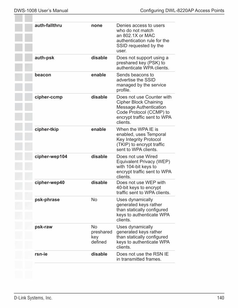
��0
DWS-1008 User’s Manual
D-Link Systems, Inc.
Configuring DWL-8220AP Access Points
auth-fallthru none Denies access to users who do not match an 802.1X or MAC authentication rule for the SSID requested by the user.
auth-psk disable Does not support using a preshared key (PSK) to authenticate WPA clients.
beacon enable Sends beacons to advertise the SSID managed by the service profile.
cipher-ccmp disable Does not use Counter with Cipher Block Chaining Message Authentication Code Protocol (CCMP) to encrypt traffic sent to WPA clients.
cipher-tkip enable When the WPA IE is enabled, uses Temporal Key Integrity Protocol (TKIP) to encrypt traffic sent to WPA clients.
cipher-wep104 disable Does not use Wired Equivalent Privacy (WEP) with 104-bit keys to encrypt traffic sent to WPA clients.
cipher-wep40 disable Does not use WEP with 40-bit keys to encrypt traffic sent to WPA clients.
psk-phrase No Uses dynamically generated keys rather than statically configured keys to authenticate WPA clients.
psk-raw No preshared key defined
Uses dynamically generated keys rather than statically configured keys to authenticate WPA clients.
rsn-ie disable Does not use the RSN IE in transmitted frames.
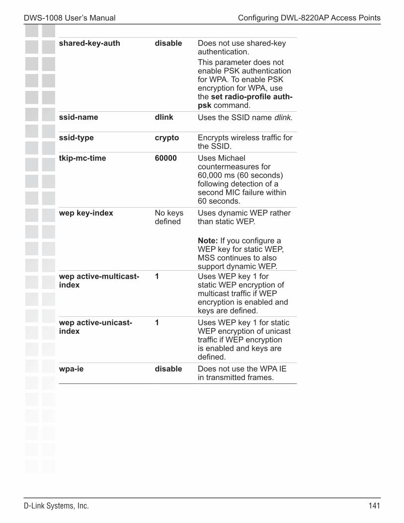
���
DWS-1008 User’s Manual
D-Link Systems, Inc.
Configuring DWL-8220AP Access Points
shared-key-auth disable Does not use shared-key authentication.This parameter does not enable PSK authentication for WPA. To enable PSK encryption for WPA, use the set radio-profile auth-psk command.
ssid-name dlink Uses the SSID name dlink.
ssid-type crypto Encrypts wireless traffic for the SSID.
tkip-mc-time 60000 Uses Michael countermeasures for 60,000 ms (60 seconds) following detection of a second MIC failure within 60 seconds.
wep key-index No keys defined
Uses dynamic WEP rather than static WEP.
Note: If you configure a WEP key for static WEP, MSS continues to also support dynamic WEP.
wep active-multicast-index
1 Uses WEP key 1 for static WEP encryption of multicast traffic if WEP encryption is enabled and keys are defined.
wep active-unicast-index
1 Uses WEP key 1 for static WEP encryption of unicast traffic if WEP encryption is enabled and keys are defined.
wpa-ie disable Does not use the WPA IE in transmitted frames.
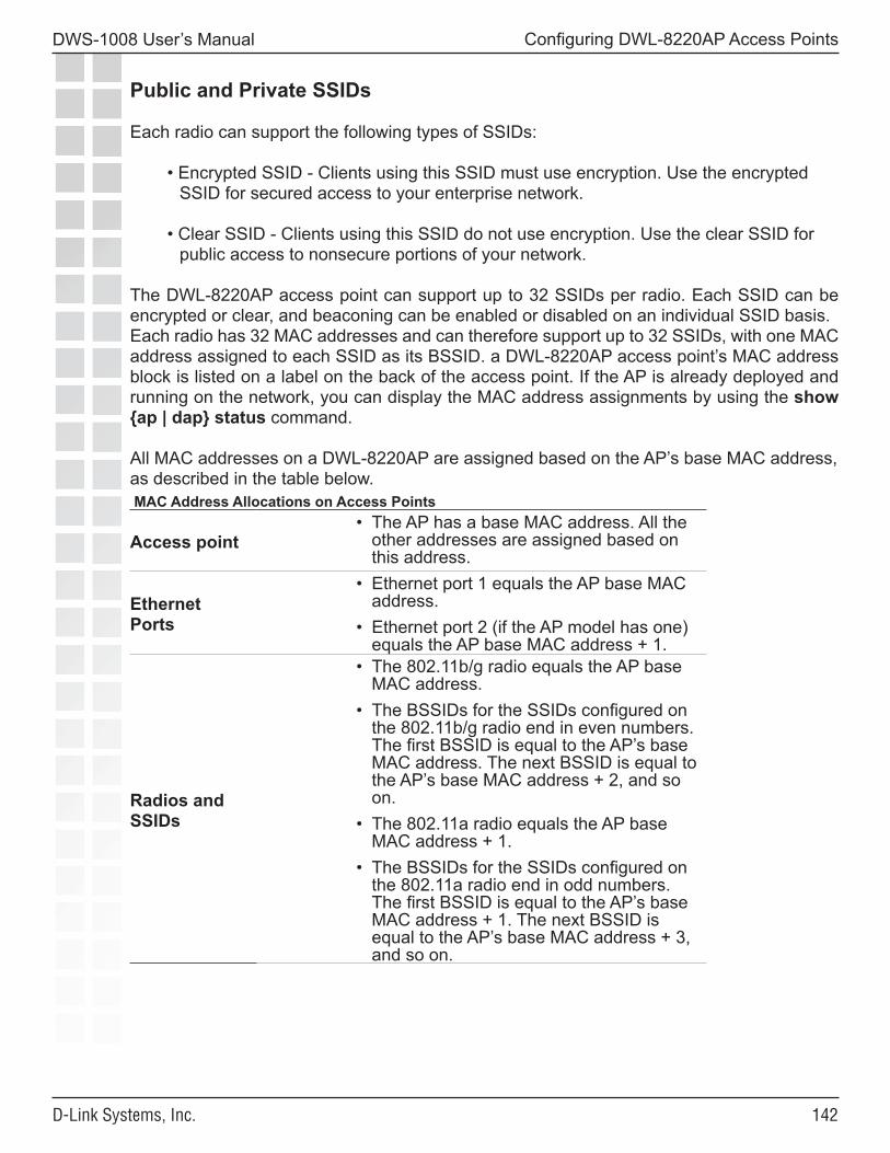
���
DWS-1008 User’s Manual
D-Link Systems, Inc.
Configuring DWL-8220AP Access Points
Public and Private SSIDs
Each radio can support the following types of SSIDs:
• Encrypted SSID - Clients using this SSID must use encryption. Use the encrypted SSID for secured access to your enterprise network.
• Clear SSID - Clients using this SSID do not use encryption. Use the clear SSID for public access to nonsecure portions of your network.
The DWL-8220AP access point can support up to 32 SSIDs per radio. Each SSID can be encrypted or clear, and beaconing can be enabled or disabled on an individual SSID basis. Each radio has 32 MAC addresses and can therefore support up to 32 SSIDs, with one MAC address assigned to each SSID as its BSSID. a DWL-8220AP access point’s MAC address block is listed on a label on the back of the access point. If the AP is already deployed and running on the network, you can display the MAC address assignments by using the show {ap | dap} status command.
All MAC addresses on a DWL-8220AP are assigned based on the AP’s base MAC address, as described in the table below. MAC Address Allocations on Access Points
Access point • The AP has a base MAC address. All the
other addresses are assigned based on this address.
Ethernet Ports
• Ethernet port 1 equals the AP base MAC address.
• Ethernet port 2 (if the AP model has one) equals the AP base MAC address + 1.
Radios and SSIDs
• The 802.11b/g radio equals the AP base MAC address.
• The BSSIDs for the SSIDs configured on the 802.11b/g radio end in even numbers. The first BSSID is equal to the AP’s base MAC address. The next BSSID is equal to the AP’s base MAC address + 2, and so on.
• The 802.11a radio equals the AP base MAC address + 1.
• The BSSIDs for the SSIDs configured on the 802.11a radio end in odd numbers. The first BSSID is equal to the AP’s base MAC address + 1. The next BSSID is equal to the AP’s base MAC address + 3, and so on.
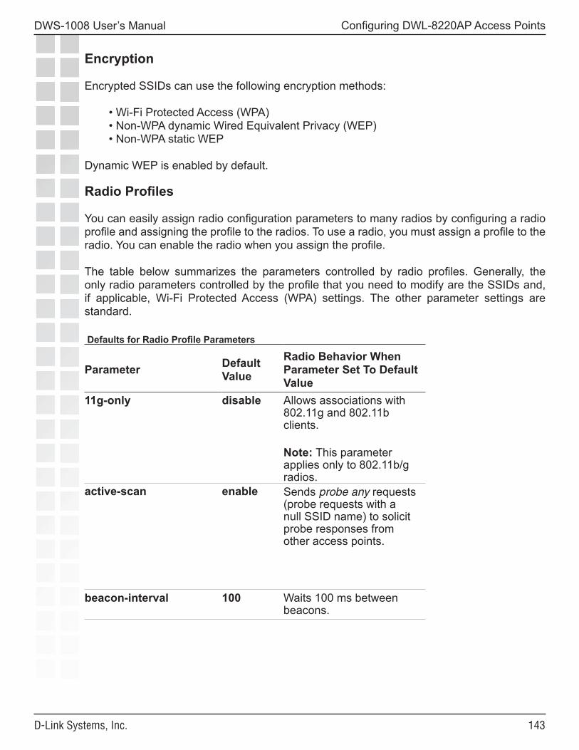
���
DWS-1008 User’s Manual
D-Link Systems, Inc.
Configuring DWL-8220AP Access Points
Encryption
Encrypted SSIDs can use the following encryption methods:
• Wi-Fi Protected Access (WPA)• Non-WPA dynamic Wired Equivalent Privacy (WEP)• Non-WPA static WEP
Dynamic WEP is enabled by default.
Radio Profiles
You can easily assign radio configuration parameters to many radios by configuring a radio profile and assigning the profile to the radios. To use a radio, you must assign a profile to the radio. You can enable the radio when you assign the profile.
The table below summarizes the parameters controlled by radio profiles. Generally, the only radio parameters controlled by the profile that you need to modify are the SSIDs and, if applicable, Wi-Fi Protected Access (WPA) settings. The other parameter settings are standard.
Defaults for Radio Profile Parameters
Parameter Default Value
Radio Behavior When Parameter Set To Default Value
11g-only disable Allows associations with 802.11g and 802.11b clients.
Note: This parameter applies only to 802.11b/g radios.
active-scan enable Sends probe any requests (probe requests with a null SSID name) to solicit probe responses from other access points.
beacon-interval 100 Waits 100 ms between beacons.
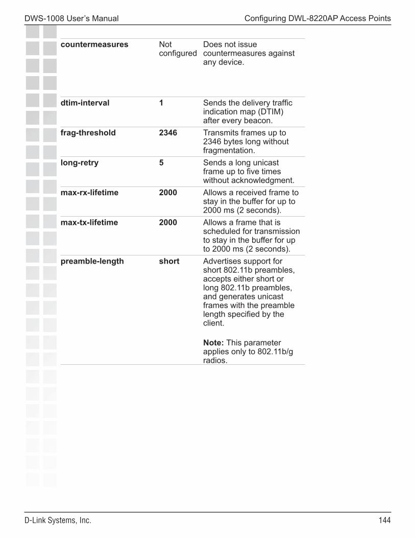
���
DWS-1008 User’s Manual
D-Link Systems, Inc.
Configuring DWL-8220AP Access Points
countermeasures Not configured
Does not issue countermeasures against any device.
dtim-interval 1 Sends the delivery traffic indication map (DTIM) after every beacon.
frag-threshold 2346 Transmits frames up to 2346 bytes long without fragmentation.
long-retry 5 Sends a long unicast frame up to five times without acknowledgment.
max-rx-lifetime 2000 Allows a received frame to stay in the buffer for up to 2000 ms (2 seconds).
max-tx-lifetime 2000 Allows a frame that is scheduled for transmission to stay in the buffer for up to 2000 ms (2 seconds).
preamble-length short Advertises support for short 802.11b preambles, accepts either short or long 802.11b preambles, and generates unicast frames with the preamble length specified by the client.
Note: This parameter applies only to 802.11b/g radios.
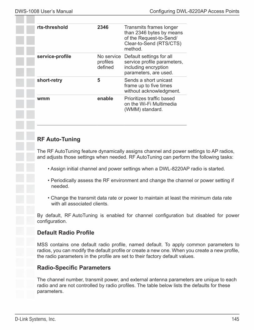
���
DWS-1008 User’s Manual
D-Link Systems, Inc.
Configuring DWL-8220AP Access Points
rts-threshold 2346 Transmits frames longer than 2346 bytes by means of the Request-to-Send/Clear-to-Send (RTS/CTS) method.
service-profile No service profiles defined
Default settings for all service profile parameters, including encryption parameters, are used.
short-retry 5 Sends a short unicast frame up to five times without acknowledgment.
wmm enable Prioritizes traffic based on the Wi-Fi Multimedia (WMM) standard.
RF Auto-Tuning
The RF AutoTuning feature dynamically assigns channel and power settings to AP radios, and adjusts those settings when needed. RF AutoTuning can perform the following tasks:
• Assign initial channel and power settings when a DWL-8220AP radio is started.
• Periodically assess the RF environment and change the channel or power setting if needed.
• Change the transmit data rate or power to maintain at least the minimum data rate with all associated clients.
By default, RF AutoTuning is enabled for channel configuration but disabled for power configuration.
Default Radio Profile
MSS contains one default radio profile, named default. To apply common parameters to radios, you can modify the default profile or create a new one. When you create a new profile, the radio parameters in the profile are set to their factory default values.
Radio-Specific Parameters
The channel number, transmit power, and external antenna parameters are unique to each radio and are not controlled by radio profiles. The table below lists the defaults for these parameters.
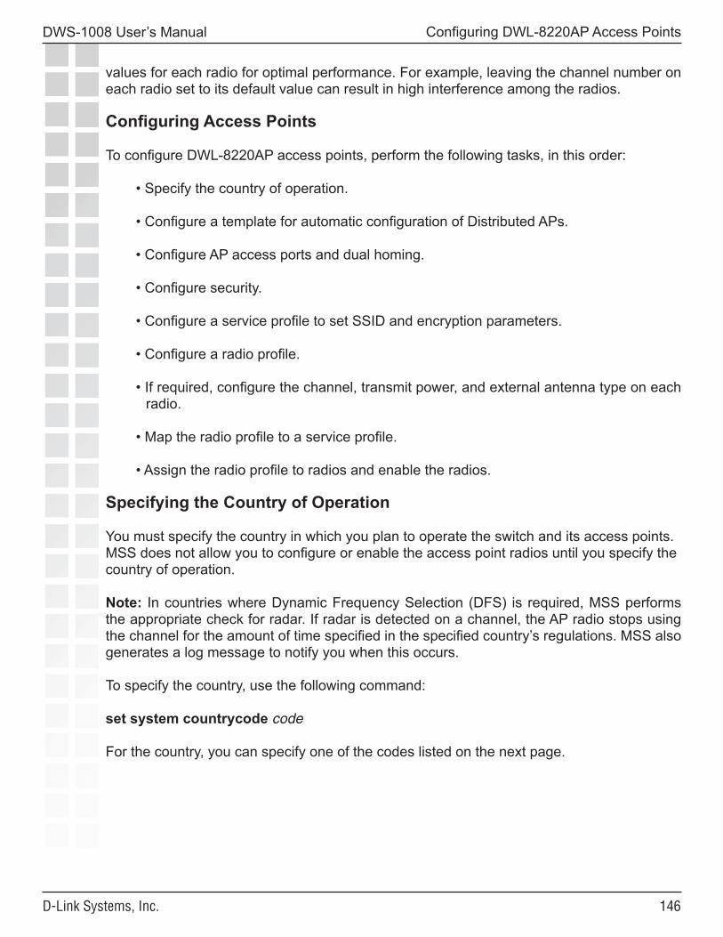
���
DWS-1008 User’s Manual
D-Link Systems, Inc.
Configuring DWL-8220AP Access Points
values for each radio for optimal performance. For example, leaving the channel number on each radio set to its default value can result in high interference among the radios.
Configuring Access Points
To configure DWL-8220AP access points, perform the following tasks, in this order:
• Specify the country of operation.
• Configure a template for automatic configuration of Distributed APs.
• Configure AP access ports and dual homing.
• Configure security.
• Configure a service profile to set SSID and encryption parameters.
• Configure a radio profile.
• If required, configure the channel, transmit power, and external antenna type on each radio.
• Map the radio profile to a service profile.
• Assign the radio profile to radios and enable the radios.
Specifying the Country of Operation
You must specify the country in which you plan to operate the switch and its access points. MSS does not allow you to configure or enable the access point radios until you specify the country of operation.
Note: In countries where Dynamic Frequency Selection (DFS) is required, MSS performs the appropriate check for radar. If radar is detected on a channel, the AP radio stops using the channel for the amount of time specified in the specified country’s regulations. MSS also generates a log message to notify you when this occurs.
To specify the country, use the following command:
set system countrycode code
For the country, you can specify one of the codes listed on the next page.
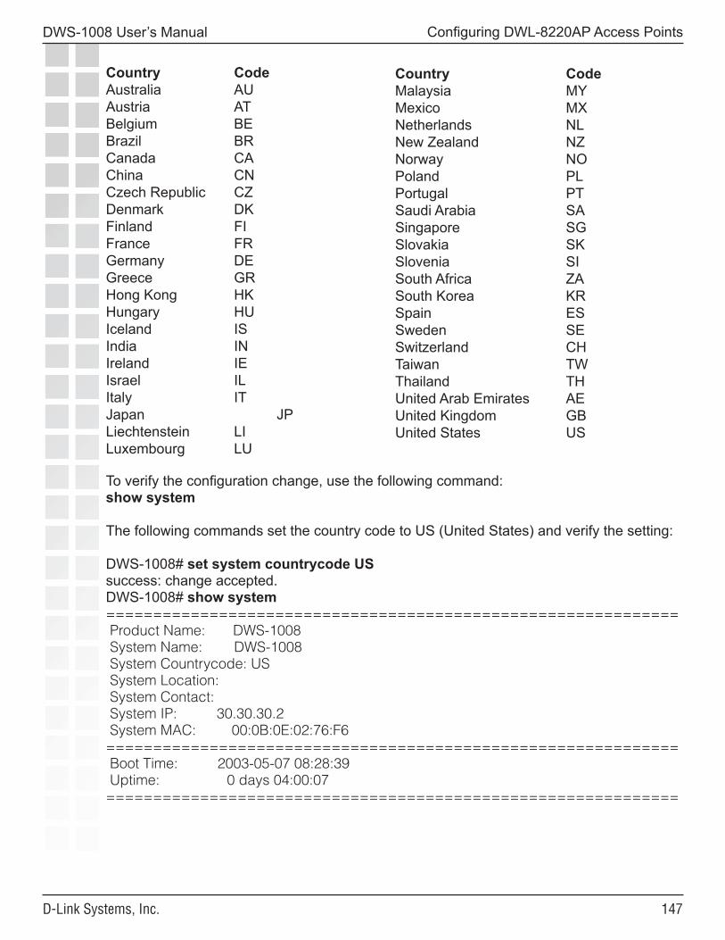
���
DWS-1008 User’s Manual
D-Link Systems, Inc.
Configuring DWL-8220AP Access Points
To verify the configuration change, use the following command:show system
The following commands set the country code to US (United States) and verify the setting:
DWS-1008# set system countrycode USsuccess: change accepted.DWS-1008# show system============================================================= Product Name: DWS-1008 System Name: DWS-1008 System Countrycode: US System Location: System Contact: System IP: 30.30.30.2 System MAC: 00:0B:0E:02:76:F6============================================================= Boot Time: 2003-05-07 08:28:39 Uptime: 0 days 04:00:07=============================================================
Country CodeAustralia AUAustria ATBelgium BEBrazil BRCanada CAChina CNCzech Republic CZDenmark DKFinland FIFrance FRGermany DEGreece GRHong Kong HKHungary HUIceland ISIndia INIreland IEIsrael ILItaly ITJapan JPLiechtenstein LILuxembourg LU
Country CodeMalaysia MYMexico MXNetherlands NLNew Zealand NZNorway NOPoland PLPortugal PTSaudi Arabia SASingapore SGSlovakia SKSlovenia SISouth Africa ZASouth Korea KRSpain ESSweden SESwitzerland CHTaiwan TWThailand THUnited Arab Emirates AEUnited Kingdom GBUnited States US

���
DWS-1008 User’s Manual
D-Link Systems, Inc.
Configuring DWL-8220AP Access Points
============================================================= Fan status: fan1 OK fan2 OK fan3 OK Temperature: temp1 ok temp2 ok temp3 ok PSU Status: Lower Power Supply DC ok AC ok Upper Power Supply missing Memory: 115.09/496.04 (23%) Total Power Over Ethernet : 32.000=============================================================
Configuring a Template for Automatic AP Configuration
You can use a configuration template to deploy unconfigured Distributed APs. A Distributed AP that does not have a configuration on an switch can receive its configuration from the template instead.
The template assigns a Distributed AP number and name to the AP, from among the unused valid AP numbers available on the switch. The template also configures the AP with the AP and radio parameter settings in the template. The AP and radio parameter settings in the template are configurable.
The template does not control SSIDs, encryption parameters, or any other parameters managed by service profiles. You still need to configure a service profile separately for each SSID. A switch can have one template.
Configured APs Have Precedence Over Unconfigured APs
When a switch determines the DWS-1008 IP address to send to a booting AP, the switch gives preference to APs that are already configured, over unconfigured APs that require a template. The DWS-1008 can direct a configured AP to a switch that has active APs configured using the template, even if the switch does not have capacity for more active APs. In this case, the DWS-1008 randomly selects a DWL-8220AP using the template to disconnect, and accepts a connection from the configured AP in its place.
The disconnected AP can then begin the boot process again to find another switch that has a template. When the AP is disconnected, the AP’s clients experience a service disruption, and will attempt to associate with another AP if available to reconnect to the SSID they were using. If another AP is not available to a client, the client can still reconnect after the disconnected AP is connected to a new DWS-1008 and finishes the boot and configuration process.
Configuring a Template
The template for Distributed AP configuration is like an individual AP configuration, except the configuration has the name auto instead of a Distributed AP number. To create a template for automatic Distributed AP configuration, type the following command:
DWS-1008# set dap autosuccess: change accepted.
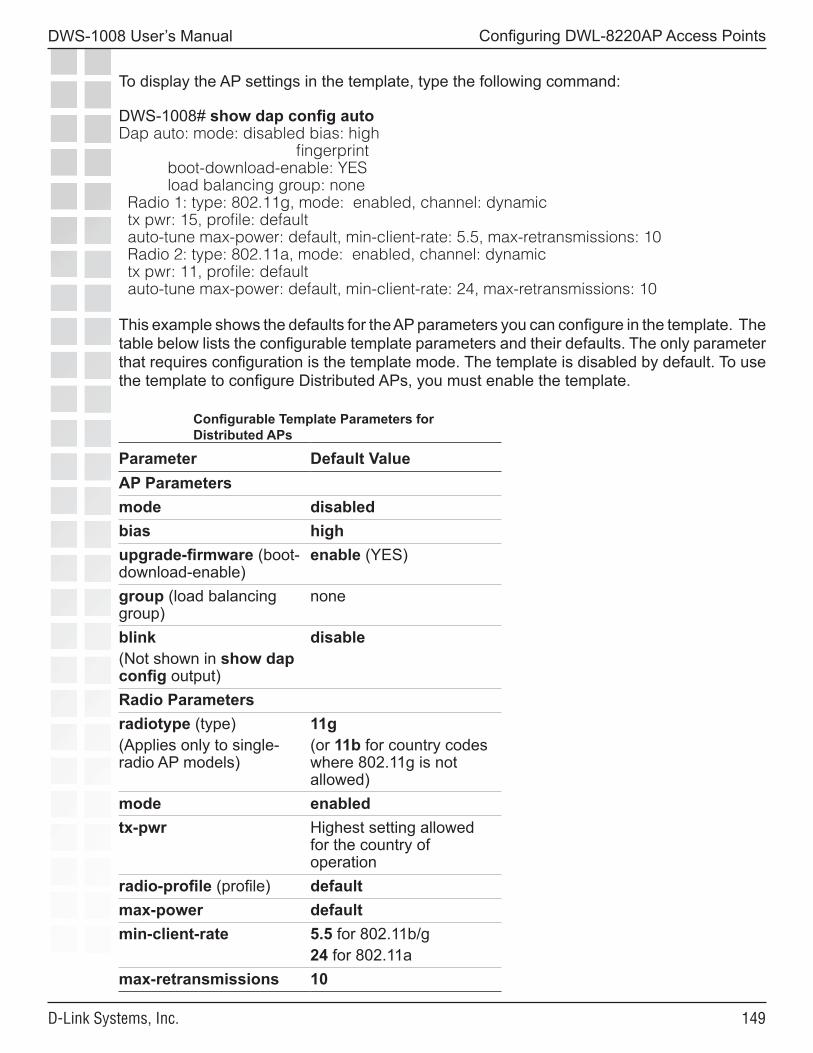
���
DWS-1008 User’s Manual
D-Link Systems, Inc.
Configuring DWL-8220AP Access Points
To display the AP settings in the template, type the following command:
DWS-1008# show dap config autoDap auto: mode: disabled bias: high fingerprint boot-download-enable: YES load balancing group: none Radio 1: type: 802.11g, mode: enabled, channel: dynamic tx pwr: 15, profile: default auto-tune max-power: default, min-client-rate: 5.5, max-retransmissions: 10 Radio 2: type: 802.11a, mode: enabled, channel: dynamic tx pwr: 11, profile: default auto-tune max-power: default, min-client-rate: 24, max-retransmissions: 10
This example shows the defaults for the AP parameters you can configure in the template. The table below lists the configurable template parameters and their defaults. The only parameter that requires configuration is the template mode. The template is disabled by default. To use the template to configure Distributed APs, you must enable the template.
Configurable Template Parameters for Distributed APs
Parameter Default ValueAP Parametersmode disabledbias highupgrade-firmware (boot-download-enable)
enable (YES)
group (load balancing group)
none
blink(Not shown in show dap config output)
disable
Radio Parametersradiotype (type)(Applies only to single-radio AP models)
11g(or 11b for country codes where 802.11g is not allowed)
mode enabledtx-pwr Highest setting allowed
for the country of operation
radio-profile (profile) defaultmax-power defaultmin-client-rate 5.5 for 802.11b/g
24 for 802.11amax-retransmissions 10
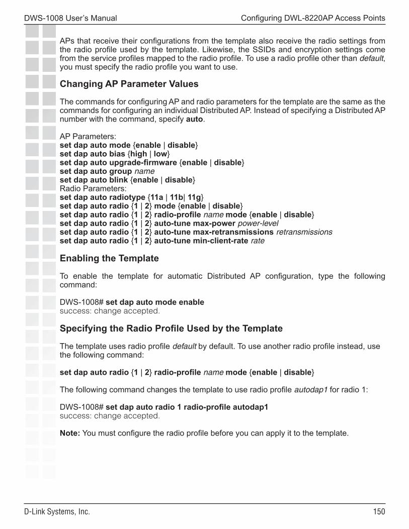
��0
DWS-1008 User’s Manual
D-Link Systems, Inc.
Configuring DWL-8220AP Access Points
APs that receive their configurations from the template also receive the radio settings from the radio profile used by the template. Likewise, the SSIDs and encryption settings come from the service profiles mapped to the radio profile. To use a radio profile other than default, you must specify the radio profile you want to use.
Changing AP Parameter Values
The commands for configuring AP and radio parameters for the template are the same as the commands for configuring an individual Distributed AP. Instead of specifying a Distributed AP number with the command, specify auto.
AP Parameters:set dap auto mode {enable | disable}set dap auto bias {high | low}set dap auto upgrade-firmware {enable | disable}set dap auto group nameset dap auto blink {enable | disable}Radio Parameters:set dap auto radiotype {11a | 11b| 11g}set dap auto radio {1 | 2} mode {enable | disable}set dap auto radio {1 | 2} radio-profile name mode {enable | disable}set dap auto radio {1 | 2} auto-tune max-power power-levelset dap auto radio {1 | 2} auto-tune max-retransmissions retransmissionsset dap auto radio {1 | 2} auto-tune min-client-rate rate
Enabling the Template
To enable the template for automatic Distributed AP configuration, type the following command:
DWS-1008# set dap auto mode enablesuccess: change accepted.
Specifying the Radio Profile Used by the Template
The template uses radio profile default by default. To use another radio profile instead, use the following command:
set dap auto radio {1 | 2} radio-profile name mode {enable | disable}
The following command changes the template to use radio profile autodap1 for radio 1:
DWS-1008# set dap auto radio 1 radio-profile autodap1success: change accepted.
Note: You must configure the radio profile before you can apply it to the template.
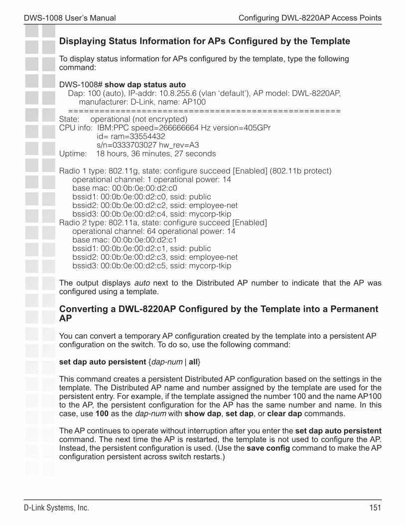
���
DWS-1008 User’s Manual
D-Link Systems, Inc.
Configuring DWL-8220AP Access Points
Displaying Status Information for APs Configured by the Template
To display status information for APs configured by the template, type the following command:
DWS-1008# show dap status auto Dap: 100 (auto), IP-addr: 10.8.255.6 (vlan ‘default’), AP model: DWL-8220AP, manufacturer: D-Link, name: AP100 ====================================================State: operational (not encrypted)CPU info: IBM:PPC speed=266666664 Hz version=405GPr id= ram=33554432 s/n=0333703027 hw_rev=A3Uptime: 18 hours, 36 minutes, 27 seconds
Radio 1 type: 802.11g, state: configure succeed [Enabled] (802.11b protect) operational channel: 1 operational power: 14 base mac: 00:0b:0e:00:d2:c0 bssid1: 00:0b:0e:00:d2:c0, ssid: public bssid2: 00:0b:0e:00:d2:c2, ssid: employee-net bssid3: 00:0b:0e:00:d2:c4, ssid: mycorp-tkipRadio 2 type: 802.11a, state: configure succeed [Enabled] operational channel: 64 operational power: 14 base mac: 00:0b:0e:00:d2:c1 bssid1: 00:0b:0e:00:d2:c1, ssid: public bssid2: 00:0b:0e:00:d2:c3, ssid: employee-net bssid3: 00:0b:0e:00:d2:c5, ssid: mycorp-tkip
The output displays auto next to the Distributed AP number to indicate that the AP was configured using a template.
Converting a DWL-8220AP Configured by the Template into a Permanent AP
You can convert a temporary AP configuration created by the template into a persistent AP configuration on the switch. To do so, use the following command:
set dap auto persistent {dap-num | all}
This command creates a persistent Distributed AP configuration based on the settings in the template. The Distributed AP name and number assigned by the template are used for the persistent entry. For example, if the template assigned the number 100 and the name AP100 to the AP, the persistent configuration for the AP has the same number and name. In this case, use 100 as the dap-num with show dap, set dap, or clear dap commands.
The AP continues to operate without interruption after you enter the set dap auto persistent command. The next time the AP is restarted, the template is not used to configure the AP. Instead, the persistent configuration is used. (Use the save config command to make the AP configuration persistent across switch restarts.)
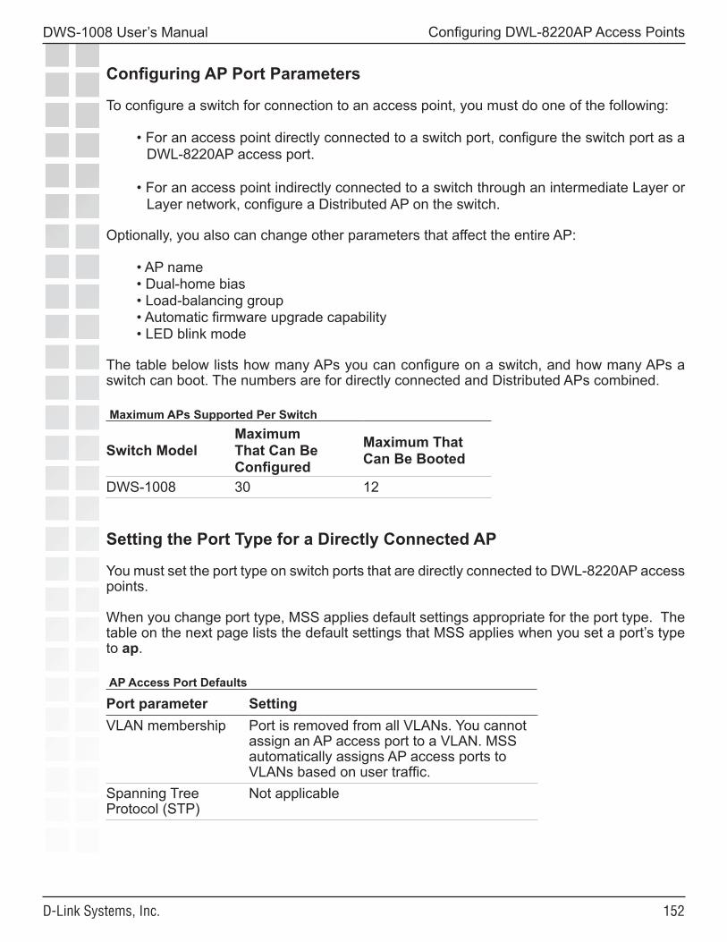
���
DWS-1008 User’s Manual
D-Link Systems, Inc.
Configuring DWL-8220AP Access Points
Configuring AP Port Parameters
To configure a switch for connection to an access point, you must do one of the following:
• For an access point directly connected to a switch port, configure the switch port as a DWL-8220AP access port.
• For an access point indirectly connected to a switch through an intermediate Layer or Layer network, configure a Distributed AP on the switch.
Optionally, you also can change other parameters that affect the entire AP:
• AP name• Dual-home bias• Load-balancing group• Automatic firmware upgrade capability• LED blink mode
The table below lists how many APs you can configure on a switch, and how many APs a switch can boot. The numbers are for directly connected and Distributed APs combined.
Maximum APs Supported Per Switch
Switch ModelMaximum That Can Be Configured
Maximum That Can Be Booted
DWS-1008 30 12
Setting the Port Type for a Directly Connected AP
You must set the port type on switch ports that are directly connected to DWL-8220AP access points.
When you change port type, MSS applies default settings appropriate for the port type. The table on the next page lists the default settings that MSS applies when you set a port’s type to ap.
AP Access Port Defaults
Port parameter SettingVLAN membership Port is removed from all VLANs. You cannot
assign an AP access port to a VLAN. MSS automatically assigns AP access ports to VLANs based on user traffic.
Spanning Tree Protocol (STP)
Not applicable
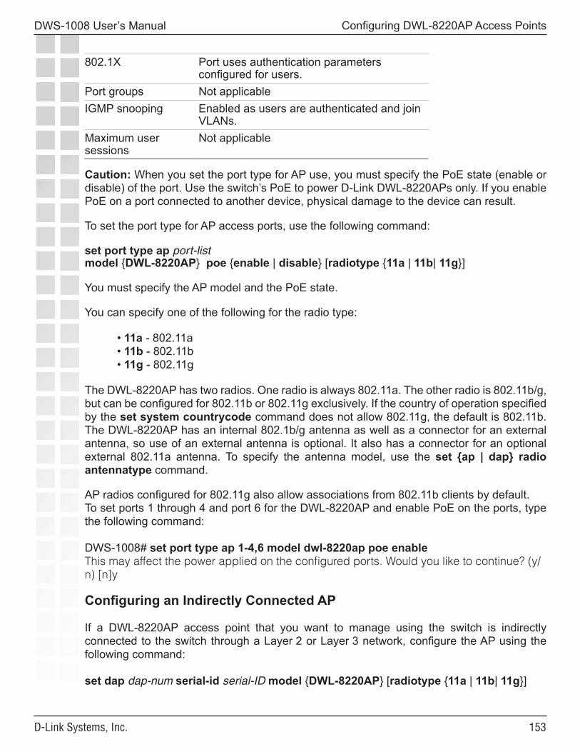
���
DWS-1008 User’s Manual
D-Link Systems, Inc.
Configuring DWL-8220AP Access Points
802.1X Port uses authentication parameters configured for users.
Port groups Not applicableIGMP snooping Enabled as users are authenticated and join
VLANs.Maximum user sessions
Not applicable
Caution: When you set the port type for AP use, you must specify the PoE state (enable or disable) of the port. Use the switch’s PoE to power D-Link DWL-8220APs only. If you enable PoE on a port connected to another device, physical damage to the device can result.
To set the port type for AP access ports, use the following command:
set port type ap port-list model {DWL-8220AP} poe {enable | disable} [radiotype {11a | 11b| 11g}]
You must specify the AP model and the PoE state.
You can specify one of the following for the radio type:
• 11a - 802.11a• 11b - 802.11b• 11g - 802.11g
The DWL-8220AP has two radios. One radio is always 802.11a. The other radio is 802.11b/g, but can be configured for 802.11b or 802.11g exclusively. If the country of operation specified by the set system countrycode command does not allow 802.11g, the default is 802.11b. The DWL-8220AP has an internal 802.1b/g antenna as well as a connector for an external antenna, so use of an external antenna is optional. It also has a connector for an optional external 802.11a antenna. To specify the antenna model, use the set {ap | dap} radio antennatype command.
AP radios configured for 802.11g also allow associations from 802.11b clients by default. To set ports 1 through 4 and port 6 for the DWL-8220AP and enable PoE on the ports, type the following command:
DWS-1008# set port type ap 1-4,6 model dwl-8220ap poe enableThis may affect the power applied on the configured ports. Would you like to continue? (y/n) [n]y
Configuring an Indirectly Connected AP
If a DWL-8220AP access point that you want to manage using the switch is indirectly connected to the switch through a Layer 2 or Layer 3 network, configure the AP using the following command:
set dap dap-num serial-id serial-ID model {DWL-8220AP} [radiotype {11a | 11b| 11g}]
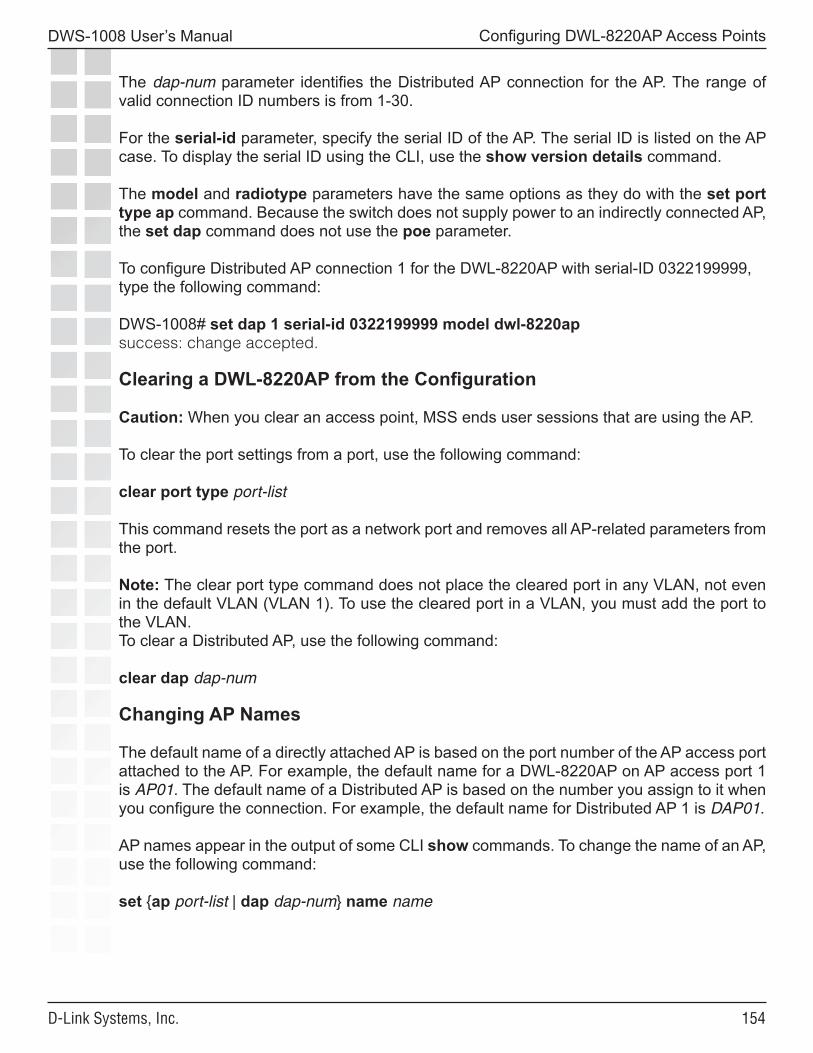
���
DWS-1008 User’s Manual
D-Link Systems, Inc.
Configuring DWL-8220AP Access Points
The dap-num parameter identifies the Distributed AP connection for the AP. The range of valid connection ID numbers is from 1-30.
For the serial-id parameter, specify the serial ID of the AP. The serial ID is listed on the AP case. To display the serial ID using the CLI, use the show version details command.
The model and radiotype parameters have the same options as they do with the set port type ap command. Because the switch does not supply power to an indirectly connected AP, the set dap command does not use the poe parameter.
To configure Distributed AP connection 1 for the DWL-8220AP with serial-ID 0322199999, type the following command:
DWS-1008# set dap 1 serial-id 0322199999 model dwl-8220apsuccess: change accepted.
Clearing a DWL-8220AP from the Configuration
Caution: When you clear an access point, MSS ends user sessions that are using the AP.
To clear the port settings from a port, use the following command:
clear port type port-list
This command resets the port as a network port and removes all AP-related parameters from the port.
Note: The clear port type command does not place the cleared port in any VLAN, not even in the default VLAN (VLAN 1). To use the cleared port in a VLAN, you must add the port to the VLAN.To clear a Distributed AP, use the following command:
clear dap dap-num
Changing AP Names
The default name of a directly attached AP is based on the port number of the AP access port attached to the AP. For example, the default name for a DWL-8220AP on AP access port 1 is AP01. The default name of a Distributed AP is based on the number you assign to it when you configure the connection. For example, the default name for Distributed AP 1 is DAP01.
AP names appear in the output of some CLI show commands. To change the name of an AP, use the following command:
set {ap port-list | dap dap-num} name name
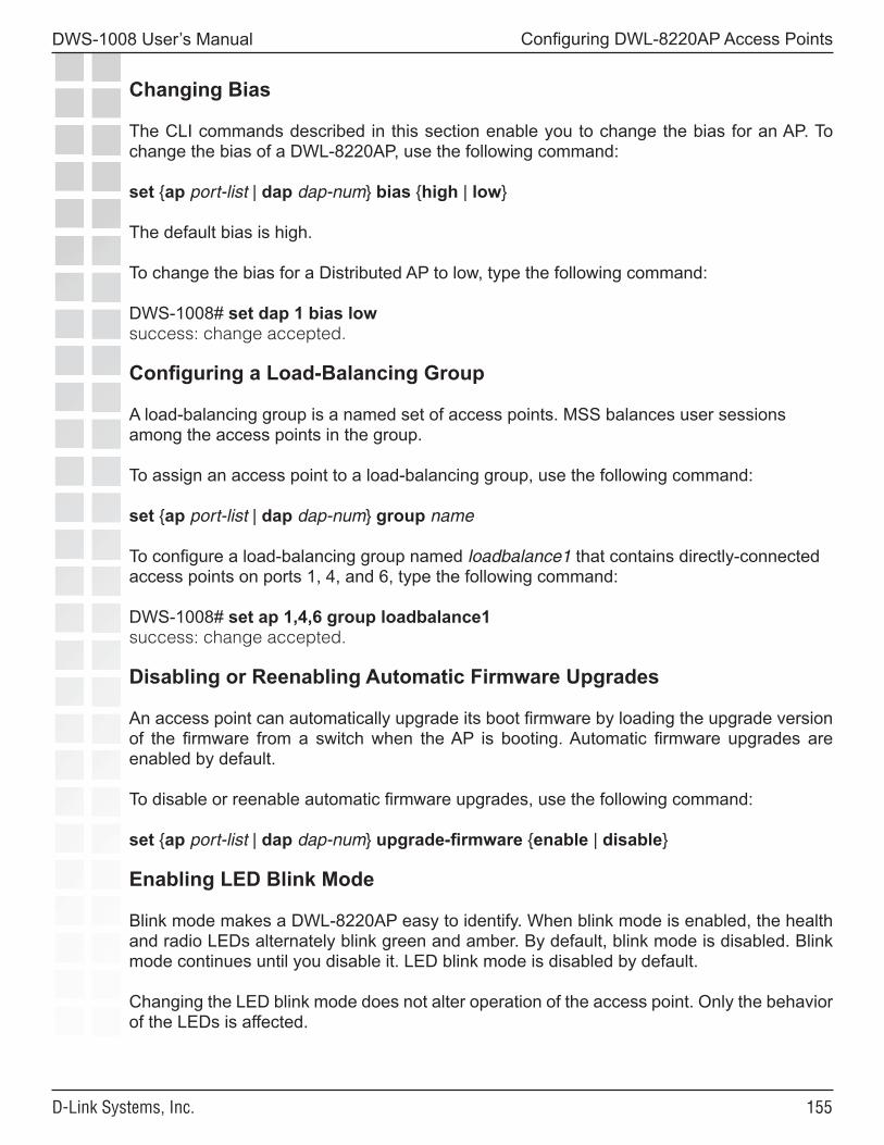
���
DWS-1008 User’s Manual
D-Link Systems, Inc.
Configuring DWL-8220AP Access Points
Changing Bias
The CLI commands described in this section enable you to change the bias for an AP. To change the bias of a DWL-8220AP, use the following command:
set {ap port-list | dap dap-num} bias {high | low}
The default bias is high.
To change the bias for a Distributed AP to low, type the following command:
DWS-1008# set dap 1 bias lowsuccess: change accepted.
Configuring a Load-Balancing Group
A load-balancing group is a named set of access points. MSS balances user sessions among the access points in the group. To assign an access point to a load-balancing group, use the following command:
set {ap port-list | dap dap-num} group name
To configure a load-balancing group named loadbalance1 that contains directly-connected access points on ports 1, 4, and 6, type the following command:
DWS-1008# set ap 1,4,6 group loadbalance1success: change accepted.
Disabling or Reenabling Automatic Firmware Upgrades
An access point can automatically upgrade its boot firmware by loading the upgrade version of the firmware from a switch when the AP is booting. Automatic firmware upgrades are enabled by default.
To disable or reenable automatic firmware upgrades, use the following command:
set {ap port-list | dap dap-num} upgrade-firmware {enable | disable}
Enabling LED Blink Mode
Blink mode makes a DWL-8220AP easy to identify. When blink mode is enabled, the health and radio LEDs alternately blink green and amber. By default, blink mode is disabled. Blink mode continues until you disable it. LED blink mode is disabled by default.
Changing the LED blink mode does not alter operation of the access point. Only the behavior of the LEDs is affected.
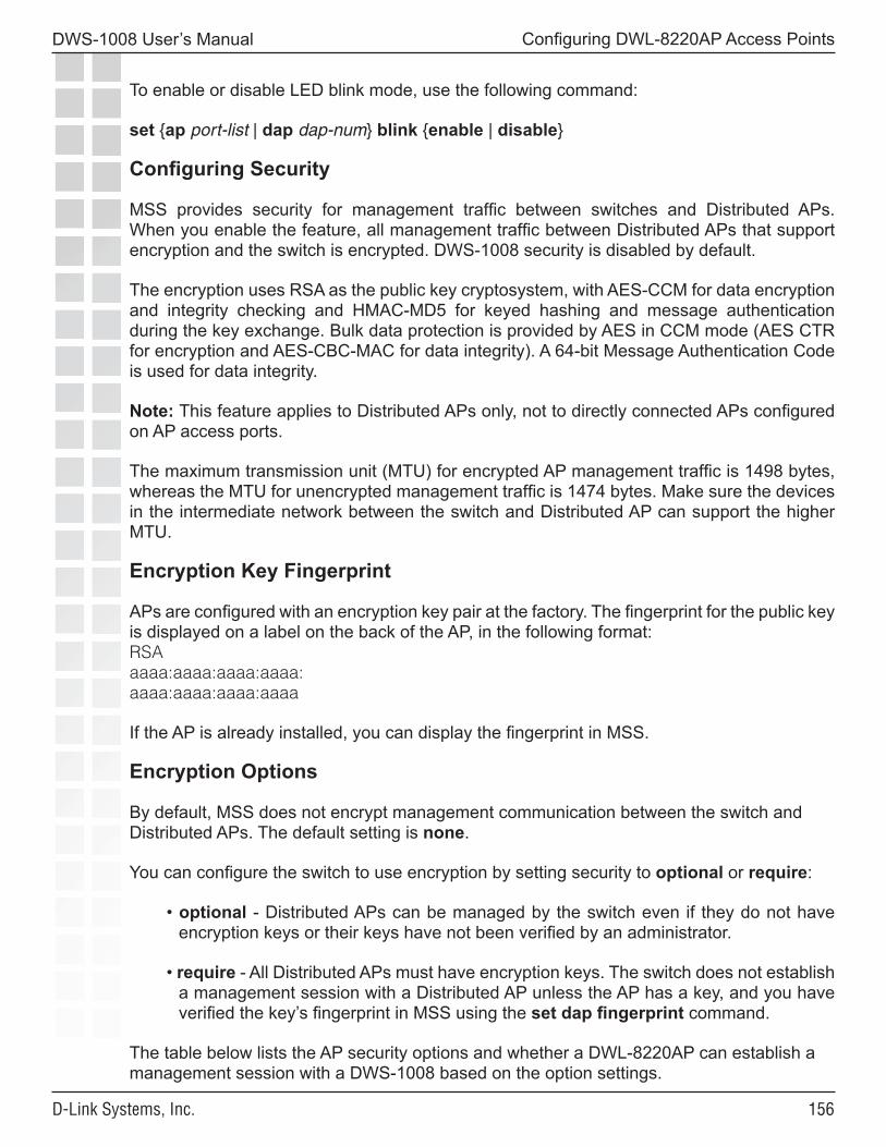
���
DWS-1008 User’s Manual
D-Link Systems, Inc.
Configuring DWL-8220AP Access Points
To enable or disable LED blink mode, use the following command:
set {ap port-list | dap dap-num} blink {enable | disable}
Configuring Security
MSS provides security for management traffic between switches and Distributed APs. When you enable the feature, all management traffic between Distributed APs that support encryption and the switch is encrypted. DWS-1008 security is disabled by default.
The encryption uses RSA as the public key cryptosystem, with AES-CCM for data encryption and integrity checking and HMAC-MD5 for keyed hashing and message authentication during the key exchange. Bulk data protection is provided by AES in CCM mode (AES CTR for encryption and AES-CBC-MAC for data integrity). A 64-bit Message Authentication Code is used for data integrity.
Note: This feature applies to Distributed APs only, not to directly connected APs configured on AP access ports.
The maximum transmission unit (MTU) for encrypted AP management traffic is 1498 bytes, whereas the MTU for unencrypted management traffic is 1474 bytes. Make sure the devices in the intermediate network between the switch and Distributed AP can support the higher MTU.
Encryption Key Fingerprint
APs are configured with an encryption key pair at the factory. The fingerprint for the public key is displayed on a label on the back of the AP, in the following format:RSAaaaa:aaaa:aaaa:aaaa:aaaa:aaaa:aaaa:aaaa
If the AP is already installed, you can display the fingerprint in MSS.
Encryption Options
By default, MSS does not encrypt management communication between the switch and Distributed APs. The default setting is none.
You can configure the switch to use encryption by setting security to optional or require:
• optional - Distributed APs can be managed by the switch even if they do not have encryption keys or their keys have not been verified by an administrator.
• require - All Distributed APs must have encryption keys. The switch does not establish a management session with a Distributed AP unless the AP has a key, and you have verified the key’s fingerprint in MSS using the set dap fingerprint command.
The table below lists the AP security options and whether a DWL-8220AP can establish a management session with a DWS-1008 based on the option settings.
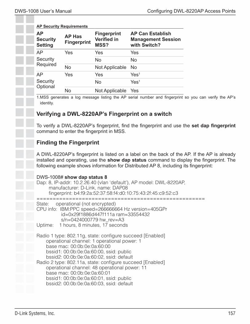
���
DWS-1008 User’s Manual
D-Link Systems, Inc.
Configuring DWL-8220AP Access Points
AP Security Requirements
AP Security Setting
AP Has Fingerprint
Fingerprint Verified in MSS?
AP Can Establish Management Session with Switch?
AP Security Required
Yes Yes YesNo No
No Not Applicable NoAPSecurity Optional
Yes Yes Yes1
No Yes1
No Not Applicable Yes1.MSS generates a log message listing the AP serial number and fingerprint so you can verify the AP’s
identity.
Verifying a DWL-8220AP’s Fingerprint on a switch
To verify a DWL-8220AP’s fingerprint, find the fingerprint and use the set dap fingerprint command to enter the fingerprint in MSS.
Finding the Fingerprint
A DWL-8220AP’s fingerprint is listed on a label on the back of the AP. If the AP is already installed and operating, use the show dap status command to display the fingerprint. The following example shows information for Distributed AP 8, including its fingerprint:
DWS-1008# show dap status 8Dap: 8, IP-addr: 10.2.26.40 (vlan ‘default’), AP model: DWL-8220AP, manufacturer: D-Link, name: DAP08 fingerprint: b4:f9:2a:52:37:58:f4:d0:10:75:43:2f:45:c9:52:c3====================================================State: operational (not encrypted)CPU info: IBM:PPC speed=266666664 Hz version=405GPr id=0x29f1886d447f111a ram=33554432 s/n=0424000779 hw_rev=A3Uptime: 1 hours, 8 minutes, 17 seconds
Radio 1 type: 802.11g, state: configure succeed [Enabled] operational channel: 1 operational power: 1 base mac: 00:0b:0e:0a:60:00 bssid1: 00:0b:0e:0a:60:00, ssid: public bssid2: 00:0b:0e:0a:60:02, ssid: defaultRadio 2 type: 802.11a, state: configure succeed [Enabled] operational channel: 48 operational power: 11 base mac: 00:0b:0e:0a:60:01 bssid1: 00:0b:0e:0a:60:01, ssid: public bssid2: 00:0b:0e:0a:60:03, ssid: default
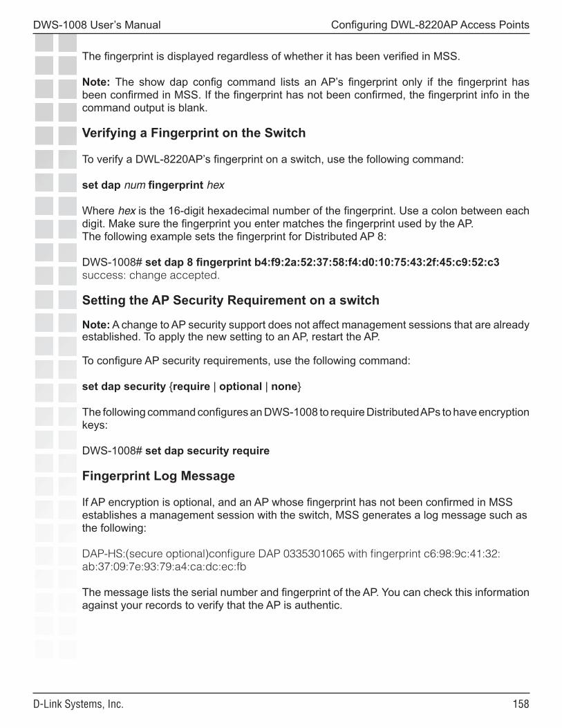
���
DWS-1008 User’s Manual
D-Link Systems, Inc.
Configuring DWL-8220AP Access Points
The fingerprint is displayed regardless of whether it has been verified in MSS.
Note: The show dap config command lists an AP’s fingerprint only if the fingerprint has been confirmed in MSS. If the fingerprint has not been confirmed, the fingerprint info in the command output is blank.
Verifying a Fingerprint on the Switch
To verify a DWL-8220AP’s fingerprint on a switch, use the following command:
set dap num fingerprint hex
Where hex is the 16-digit hexadecimal number of the fingerprint. Use a colon between each digit. Make sure the fingerprint you enter matches the fingerprint used by the AP.The following example sets the fingerprint for Distributed AP 8:
DWS-1008# set dap 8 fingerprint b4:f9:2a:52:37:58:f4:d0:10:75:43:2f:45:c9:52:c3success: change accepted.
Setting the AP Security Requirement on a switch
Note: A change to AP security support does not affect management sessions that are already established. To apply the new setting to an AP, restart the AP.
To configure AP security requirements, use the following command:
set dap security {require | optional | none}
The following command configures an DWS-1008 to require Distributed APs to have encryption keys:
DWS-1008# set dap security require
Fingerprint Log Message
If AP encryption is optional, and an AP whose fingerprint has not been confirmed in MSS establishes a management session with the switch, MSS generates a log message such as the following:
DAP-HS:(secure optional)configure DAP 0335301065 with fingerprint c6:98:9c:41:32:ab:37:09:7e:93:79:a4:ca:dc:ec:fb
The message lists the serial number and fingerprint of the AP. You can check this information against your records to verify that the AP is authentic.
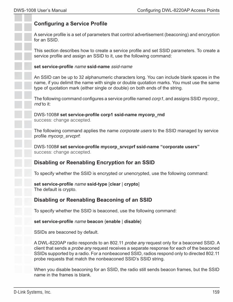
���
DWS-1008 User’s Manual
D-Link Systems, Inc.
Configuring DWL-8220AP Access Points
Configuring a Service Profile
A service profile is a set of parameters that control advertisement (beaconing) and encryption for an SSID.
This section describes how to create a service profile and set SSID parameters. To create a service profile and assign an SSID to it, use the following command:
set service-profile name ssid-name ssid-name
An SSID can be up to 32 alphanumeric characters long. You can include blank spaces in the name, if you delimit the name with single or double quotation marks. You must use the same type of quotation mark (either single or double) on both ends of the string.
The following command configures a service profile named corp1, and assigns SSID mycorp_rnd to it:
DWS-1008# set service-profile corp1 ssid-name mycorp_rndsuccess: change accepted.
The following command applies the name corporate users to the SSID managed by service profile mycorp_srvcprf:
DWS-1008# set service-profile mycorp_srvcprf ssid-name “corporate users”success: change accepted.
Disabling or Reenabling Encryption for an SSID
To specify whether the SSID is encrypted or unencrypted, use the following command:
set service-profile name ssid-type [clear | crypto]The default is crypto.
Disabling or Reenabling Beaconing of an SSID
To specify whether the SSID is beaconed, use the following command:
set service-profile name beacon {enable | disable}
SSIDs are beaconed by default.
A DWL-8220AP radio responds to an 802.11 probe any request only for a beaconed SSID. A client that sends a probe any request receives a separate response for each of the beaconed SSIDs supported by a radio. For a nonbeaconed SSID, radios respond only to directed 802.11 probe requests that match the nonbeaconed SSID’s SSID string.
When you disable beaconing for an SSID, the radio still sends beacon frames, but the SSID name in the frames is blank.
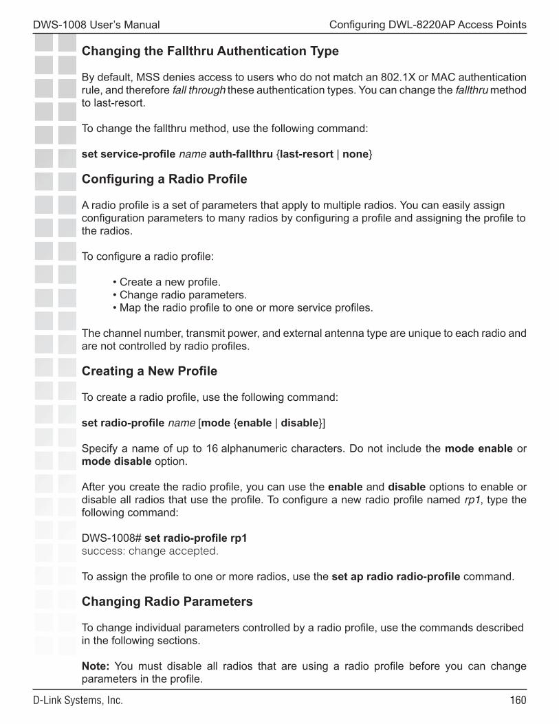
��0
DWS-1008 User’s Manual
D-Link Systems, Inc.
Configuring DWL-8220AP Access Points
Changing the Fallthru Authentication Type
By default, MSS denies access to users who do not match an 802.1X or MAC authentication rule, and therefore fall through these authentication types. You can change the fallthru method to last-resort.
To change the fallthru method, use the following command:
set service-profile name auth-fallthru {last-resort | none}
Configuring a Radio Profile
A radio profile is a set of parameters that apply to multiple radios. You can easily assign configuration parameters to many radios by configuring a profile and assigning the profile to the radios.
To configure a radio profile:
• Create a new profile.• Change radio parameters.• Map the radio profile to one or more service profiles.
The channel number, transmit power, and external antenna type are unique to each radio and are not controlled by radio profiles.
Creating a New Profile
To create a radio profile, use the following command:
set radio-profile name [mode {enable | disable}]
Specify a name of up to 16 alphanumeric characters. Do not include the mode enable or mode disable option. After you create the radio profile, you can use the enable and disable options to enable or disable all radios that use the profile. To configure a new radio profile named rp1, type the following command:
DWS-1008# set radio-profile rp1success: change accepted.
To assign the profile to one or more radios, use the set ap radio radio-profile command.
Changing Radio Parameters
To change individual parameters controlled by a radio profile, use the commands described in the following sections.
Note: You must disable all radios that are using a radio profile before you can change parameters in the profile.
���
DWS-1008 User’s Manual
D-Link Systems, Inc.
Configuring DWL-8220AP Access Points
Changing the Beacon Interval
The beacon interval is the rate at which a radio advertises its beaconed SSID(s). To change the beacon interval, use the following command:
set radio-profile name beacon-interval interval
The interval can be a value from 25 ms through 8191 ms. The default is 100. The beacon interval does not change even when advertisement is enabled for multiple SSIDs. MSS still sends one beacon for each SSID during each beacon interval.
To change the beacon interval for radio profile rp1 to 200 ms, type the following command:
DWS-1008# set radio-profile rp1 beacon-interval 200success: change accepted.
Changing the DTIM Interval
The DTIM interval specifies the number of times after every beacon that a radio sends a delivery traffic indication map (DTIM). An access point sends the multicast and broadcast frames stored in its buffers to clients who request them in response to the DTIM. The DTIM interval applies to both the beaconed SSID and the unbeaconed SSID.
The DTIM interval does not apply to unicast frames. A DWL-8220AP access point also stores unicast frames in buffer memory, but the AP includes information about the buffered unicast frames in each beacon frame. When a user station receives a beacon frame that advertises unicast frames destined for the station, the station sends a request for the frames and the AP transmits the requested frames to the user station.
To change the DTIM interval, use the following command:
set radio-profile name dtim-interval interval
The interval can be a value from 1 through 31. The default is 1.
To change the DTIM interval for radio profile rp1 to 2, type the following command:
DWS-1008# set radio-profile rp1 dtim-interval 2success: change accepted.
Changing the RTS Threshold
The RTS threshold specifies the maximum length a frame can be before a radio uses the Request-to-Send/Clear-to-Send (RTS/CTS) method to send the frame. The RTS/CTS method clears the air of other traffic to avoid corruption of the frame due to a collision with another frame.
���
DWS-1008 User’s Manual
D-Link Systems, Inc.
Configuring DWL-8220AP Access Points
When a frame is long enough for the RTS/CTS method to be applicable, the radio sends a Request-To-Send (RTS) message addressed to the intended receiver for the frame. The receiver replies with a Clear-To-Send (CTS) message. When the radio receives the CTS message, the radio transmits the frame and waits for an acknowledgment from the receiver. The radio does not transmit additional frames until receiving the acknowledgment.
Any other user station that overhears the RTS or CTS message stops transmitting until the station overhears the acknowledgment message. To change the RTS threshold, use the following command:
set radio-profile name rts-threshold threshold
The threshold can be a value from 256 bytes through 3000 bytes. The default is 2346. To change the RTS threshold for radio profile rp1 to 1500 bytes, type the following command:
DWS-1008# set radio-profile rp1 rts-threshold 1500success: change accepted.
Changing the Fragmentation Threshold
The fragmentation threshold specifies the longest a frame can be without being fragmented into multiple frames by a radio before transmission. To change the fragmentation threshold, use the following command:
set radio-profile name frag-threshold threshold
The threshold can be a value from 256 through 2346. The default is 2346. To change the fragmentation threshold for radio profile rp1 to 1500 bytes, type the following command:
DWS-1008# set radio-profile rp1 frag-threshold 1500success: change accepted.
Changing the Short Retry Threshold
The short retry threshold specifies the number of times a radio can send a short unicast frame without receiving an acknowledgment for the frame. A short unicast frame is a frame that is shorter than the RTS threshold.
To change the short retry threshold, use the following command:
set radio-profile name short-retry threshold
The threshold can be a value from 1 through 15. The default is 5. To change the short retry threshold for radio profile rp1 to 3, type the following command:
DWS-1008# set radio-profile rp1 short-retry 3success: change accepted.
���
DWS-1008 User’s Manual
D-Link Systems, Inc.
Configuring DWL-8220AP Access Points
Changing the Long Retry Threshold
The long retry threshold specifies the number of times a radio can send a long unicast frame without receiving an acknowledgment for the frame. A long unicast frame is a frame that is equal to or longer than the RTS threshold.
To change the long retry threshold, use the following command:
set radio-profile name long-retry threshold
The threshold can be a value from 1 through 15. The default is 5. To change the long retry threshold for radio profile rp1 to 8, type the following command:
DWS-1008# set radio-profile rp1 long-retry 8success: change accepted.
Changing the Maximum Receive Threshold
The maximum receive threshold specifies the number of milliseconds a frame received by a radio can remain in buffer memory. To change the maximum receive lifetime, use the following command:
set radio-profile name max-rx-lifetime time
The time can be from 500 ms (0.5 second) through 250,000 ms (250 seconds). The default is 2000 ms (2 seconds).
To change the maximum receive threshold for radio profile rp1 to 4000 ms, type the following command:
DWS-1008# set radio-profile rp1 max-rx-lifetime 4000success: change accepted.
Changing the Maximum Transmit Threshold
The maximum transmission threshold specifies the number of milliseconds a frame scheduled to be transmitted by a radio can remain in buffer memory. To change the maximum transmit lifetime, use the following command:
set radio-profile name max-tx-lifetime time
The time can be from 500 ms (0.5 second) through 250,000 ms (250 seconds). The default is 2000 ms (2 seconds).
To change the maximum transmit threshold for radio profile rp1 to 4000 ms, type the following command:
DWS-1008# set radio-profile rp1 max-tx-lifetime 4000success: change accepted.

���
DWS-1008 User’s Manual
D-Link Systems, Inc.
Configuring DWL-8220AP Access Points
Disabling 802.11b Client Associations on 802.11b/g Radios
By default, an 802.11b/g radio allows associations from 802.11b clients as well as 802.11g clients. The radio requires a client to support the 802.11b data rates but client support for the higher 802.11g rates is optional. This radio configuration allows both types of clients to associate with the radio and is useful in networks that have a mixture of both types of clients. When 802.11b traffic is detected by an 802.11b/g radio, the radio enters protection mode. Protection mode guards against 802.11b interference with 802.11g traffic that is at data rates higher than the 802.11b rates. Because 802.11b clients cannot detect the traffic at data rates higher than are supported by 802.11b, the clients might cause interference by sending traffic while 802.11g access points or clients also are sending traffic.
To guard against interference, an 802.11b/g radio in protection mode sends messages while 802.11g traffic at higher data rates is being sent, to inform 802.11b devices about the 802.11g traffic and reserve bandwidth for the traffic. Protection mode remains in effect until 60 seconds after the last 802.11b traffic is detected by the 802.11b/g radio.
Protection mode lowers overall traffic throughput due to the additional messages sent by 802.11b/g radios. You can configure the 802.11b/g radios in a radio profile to reject association attempts by 802.11b clients so that protection mode is less likely to be required. In this case, the 802.11b/g radios require a client to support all the 802.11g rates.
Note: Even when association of 802.11b clients is disabled, if an 802.11b/g radio detects a beacon from an 802.11b network, the radio enters protection mode to protect against interference.
To configure 802.11b/g radios to reject association attempts from 802.11b clients, use the following command:
set radio-profile name 11g-only {enable | disable}
To configure the 802.11b/g radios in radio profile rp1 to allow associations from 802.11g clients only, type the following command:
DWS-1008# set radio-profile rp1 11g-only enablesuccess: change accepted.
Changing the Preamble Length
By default, 802.11b/g radios advertise support for frames with short preambles and can support frames with short or long preambles.
An 802.11b/g radio generates unicast frames to send to a client with the preamble length specified by the client. An 802.11b/g radio always uses a long preamble in beacons, probe responses, and other broadcast or multicast traffic.
���
DWS-1008 User’s Manual
D-Link Systems, Inc.
Configuring DWL-8220AP Access Points
Generally, clients assume access points require long preambles and request to use short preambles only if the access point with which they are associated advertises support for short preambles. You can disable the advertisement of support for short preambles by setting the preamble length value to long. In this case, clients assume that the access point supports long preambles only and the clients request long preambles.
Changing the preamble length value affects only the support advertised by the radio. Regardless of the preamble length setting (short or long), an 802.11b/g radio accepts and can generate 802.11b/g frames with either short or long preambles.
If any client associated with an 802.11b/g radio uses long preambles for unicast traffic, the access point still accepts frames with short preambles but does not transmit any frames with short preambles. This change also occurs if the access point overhears a beacon from an 802.11b/g radio on another access point that indicates the radio has clients that require long preambles. The default preamble length value is short. This command does not apply to 802.11a radios.
To change the preamble length advertised by 802.11b/g radios, use the following command:
set radio-profile name preamble-length {long | short}
To configure 802.11b/g radios that use the radio profile rp_long to advertise support for long preambles instead of short preambles, type the following command:
DWS-1008# set radio-profile rp_long preamble-length longsuccess: change accepted.
Resetting a Radio Profile Parameter to its Default Value
To reset a radio profile parameter to its default value, use the following command:
clear radio-profile name parameter
Caution: Make sure you specify the radio profile parameter you want to reset. If you do not specify a parameter, MSS deletes the entire profile from the configuration.
All radios that use this profile must be disabled before you can delete the profile. If you specify a parameter, the setting for the parameter is reset to its default value. The settings of the other parameters are unchanged and the radio profile remains in the configuration. If you do not specify a parameter, the entire radio profile is deleted from the configuration.
To disable the radios that are using radio profile rp1 type the following command:
DWS-1008# set radio-profile rp1 mode disablesuccess: change accepted.
���
DWS-1008 User’s Manual
D-Link Systems, Inc.
Configuring DWL-8220AP Access Points
Removing a Radio ProfileTo remove a radio profile, use the following command:
clear radio-profile name
Note: You must disable all radios that are using a radio profile before you can remove the profile.
To disable the radios that are using radio profile rptest and remove the profile, type the following commands:
DWS-1008# set radio-profile rptest mode disable
DWS-1008# clear radio-profile rptestsuccess: change accepted.
Configuring Radio-Specific Parameters
The following parameters are specific to individual radios and are not controlled by a radio profile:
• Channel number• Transmit power (in decibels referred to 1 milliwatt)• External antenna model (if applicable)
These parameters have the following defaults:
• Channel number:
• The default channel number for 802.11b/g is 6. • The default channel number for 802.11a is the lowest valid channel number for
the country of operation.
• Transmit power - Highest setting allowed for the country of operation or highest setting supported on the hardware, whichever is lower
• External antenna model - internal antenna used by default
Configuring the Channel and Transmit Power
Note: If RF Auto-Tuning is enabled for channels or power, you cannot set the channels or power manually using the commands in this section.
To set the channel and transmit power of a radio, use the following commands:
set {ap port-list | dap dap-num} radio {1 | 2} channel channel-number
set {ap port-list | dap dap-num} radio {1 | 2} tx-power power-level
���
DWS-1008 User’s Manual
D-Link Systems, Inc.
Configuring DWL-8220AP Access Points
The parameters are shown in separate commands for simplicity. However, you can use the channel and tx-power parameters on the same command line.
Specify 1 or 2 for the radio number:
• For an 802.11b/g radio on a DWL-8220AP specify radio 1.
• For an 802.11a radio specify radio 2.
Note: The maximum transmit power you can configure on any D-Link radio is the highest setting allowed for the country of operation or the highest setting supported on the hardware, whichever is lower.
To configure the 802.11b radio on port 2 for channel 1 with a transmit power of 10 dBm, type the following command:
DWS-1008# set ap 2 radio 1 channel 1 tx-power 10success: change accepted.
To configure the 802.11a radio on port 5 for channel 36 with a transmit power of 10 dBm, type the following command:
DWS-1008# set ap 5 radio 2 channel 36 tx-power 10success: change accepted.
You also can change the channel and transmit power on an individual basis.
Configuring the External Antenna Model
The DWL-8220AP has an internal antennas but can use an external antennas. The DWL-8220AP uses the internal antennas by default.
To specify the external antenna model, use the following command:
set {ap port-list | dap dap-num} radio {1 antennatype ANT1060 | ANT1120 | ANT1180 | internal} | {2 antennatype ANT5060 | ANT5120 | ANT5180 | internal}
To configure antenna model ANT-1060 for a DWL-8220AP on Distributed AP 1, type the following command:
DWS-1008# set dap 1 radio 1 antennatype ANT1060success: change accepted.
Mapping the Radio Profile to Service Profiles
To assign SSIDs to radios, you must map the service profiles for the SSIDs to the radio profile that is assigned to the radios.
���
DWS-1008 User’s Manual
D-Link Systems, Inc.
Configuring DWL-8220AP Access Points
To map a radio profile to a service profile, use the following command:
set radio-profile name service-profile name
The following command maps service-profile wpa_clients to radio profile rp2:
DWS-1008# set radio-profile rp2 service-profile wpa_clientssuccess: change accepted.
Assigning a Radio Profile and Enabling Radios
To assign a radio profile to radios, use the following command:
set {ap port-list | dap dap-num} radio {1 | 2} radio-profile name mode {enable | disable}
To assign radio profile rp1 to radio 1 on ports 1-3, and 6 and enable the radios, type the following command:
DWS-1008# set ap 1-3,6 radio 1 radio-profile rp1 mode enablesuccess: change accepted.
To assign radio profile rp1 to radio 2 on ports 1-4 and port 6 and enable the radios, type the following command:
DWS-1008# set ap 1-4,6 radio 2 radio-profile rp1 mode enablesuccess: change accepted.
To disable radio 1 on port 6 without disabling the other radios using radio profile rp1, type the following command:
DWS-1008# set ap 6 radio 1 radio-profile rp1 mode disable
Disabling or Reenabling Radios
You can disable or reenable radios on a radio profile basis or individual basis. You also can reset a radio to its factory default settings.
Enabling or Disabling Individual Radios
To disable or reenable an access point radio, use the following command:
set {ap port-list | dap dap-num} radio {1 | 2} mode {enable | disable}
To disable radio 2 on port 3 and 5, type the following command:
DWS-1008# set ap 3,5 radio 2 mode disablesuccess: change accepted.
���
DWS-1008 User’s Manual
D-Link Systems, Inc.
Configuring DWL-8220AP Access Points
Disabling or Reenabling All Radios Using a Profile
To disable or reenable all radios that are using a radio profile, use the following command:set radio-profile name [mode {enable | disable}]
The following command enables all radios that use radio profile rp1:
DWS-1008# set radio-profile rp1 mode enablesuccess: change accepted.
The following commands disable all radios that use radio profile rp1, change the beacon interval, then reenable the radios:
DWS-1008# set radio-profile rp1 mode disablesuccess: change accepted.
DWS-1008# set radio-profile rp1 beacon-interval 200success: change accepted.
DWS-1008# set radio-profile rp1 mode enablesuccess: change accepted.
Resetting a Radio to its Factory Default Settings
To disable an AP radio and reset it to its factory default settings, use the following command:
clear {ap port-list | dap dap-num} radio {1 | 2 | all}
This command performs the following actions:
• Sets the transmit power, channel, and external antenna type to their default values.
• Removes the radio from its radio profile and places the radio in the default radio profile.
This command does not affect the PoE setting.
To disable and reset radio 2 on the access point connected to port 3, type the following command:
DWS-1008# clear ap 3 radio 2
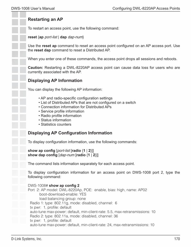
��0
DWS-1008 User’s Manual
D-Link Systems, Inc.
Configuring DWL-8220AP Access Points
Restarting an AP
To restart an access point, use the following command:
reset {ap port-list | dap dap-num}
Use the reset ap command to reset an access point configured on an AP access port. Use the reset dap command to reset a Distributed AP.
When you enter one of these commands, the access point drops all sessions and reboots.
Caution: Restarting a DWL-8220AP access point can cause data loss for users who are currently associated with the AP.
Displaying AP Information
You can display the following AP information:
• AP and radio-specific configuration settings• List of Distributed APs that are not configured on a switch• Connection information for Distributed APs• Service profile information• Radio profile information• Status information• Statistics counters
Displaying AP Configuration Information
To display configuration information, use the following commands:
show ap config [port-list [radio {1 | 2}]]show dap config [dap-num [radio {1 | 2}]]
The command lists information separately for each access point.
To display configuration information for an access point on DWS-1008 port 2, type the following command:
DWS-1008# show ap config 2Port 2: AP model: DWL-8220Ap, POE: enable, bias: high, name: AP02 boot-download-enable: YES load balancing group: none Radio 1: type: 802.11g, mode: disabled, channel: 6 tx pwr: 1, profile: default auto-tune max-power: default, min-client-rate: 5.5, max-retransmissions: 10 Radio 2: type: 802.11a, mode: disabled, channel: 36 tx pwr: 1, profile: default auto-tune max-power: default, min-client-rate: 24, max-retransmissions: 10

���
DWS-1008 User’s Manual
D-Link Systems, Inc.
Configuring DWL-8220AP Access Points
To display configuration information for a Distributed AP access point configured on connection 1, type the following command:
DWS-1008# show dap config 1Dap 1: serial-id: 12345678, AP model: DWL-8220AP, bias: high, name: DAP01 fingerprint: b4:f9:2a:52:37:58:f4:d0:10:75:43:2f:45:c9:52:c3 boot-download-enable: YES load balancing group: none Radio 1: type: 802.11g, mode: disabled, channel: 6 tx pwr: 1, profile: default auto-tune max-power: default, min-client-rate: 5.5, max-retransmissions: 10 Radio 2: type: 802.11a, mode: disabled, channel: 36 tx pwr: 1, profile: default auto-tune max-power: default, min-client-rate: 24, max-retransmissions: 10
Displaying a List of Distributed APs
To display a list of the Distributed APs configured on switches on your network, use the following command:
show dap global [dap-num | serial-id serial-ID]
This command lists the System IP addresses of all the switches on which each Distributed AP is configured, and lists the bias for the AP on each switch. For each Distributed AP that is configured on the switch on which you use the command, the connection number is also listed.
Displaying a List of Distributed APs that Are Not Configured
To display a list on Distributed APs that are not configured, use the following command:
show dap unconfigured
The following command displays information for two Distributed APs that are not configured:
DWS-1008# show dap unconfigured Total number of entries: 2Serial Id Model IP Address Port Vlan-----------------------------------------------------------------------------0333001287 DWL-8220AP 10.3.8.54 3 default0333001285 DWL-8220AP 10.3.8.57 5 vlan-eng
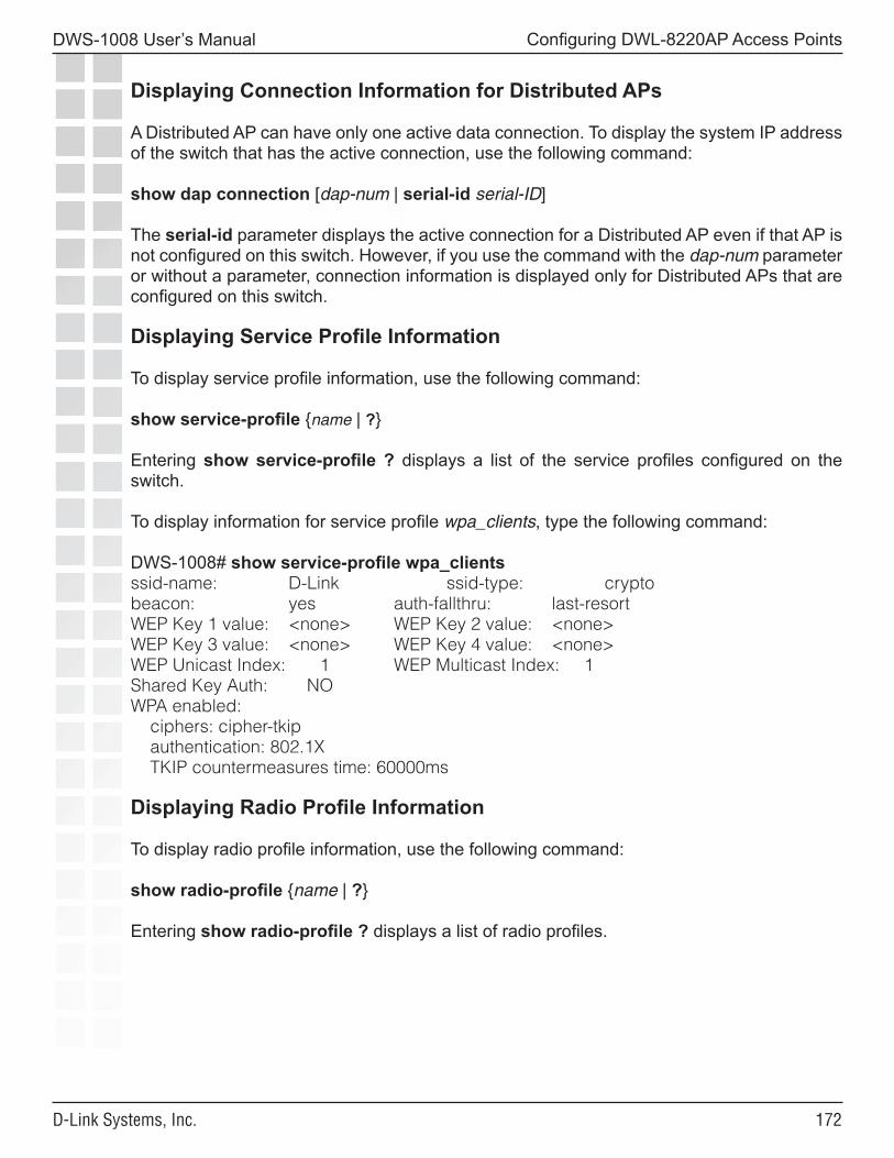
���
DWS-1008 User’s Manual
D-Link Systems, Inc.
Configuring DWL-8220AP Access Points
Displaying Connection Information for Distributed APs
A Distributed AP can have only one active data connection. To display the system IP address of the switch that has the active connection, use the following command:
show dap connection [dap-num | serial-id serial-ID]
The serial-id parameter displays the active connection for a Distributed AP even if that AP is not configured on this switch. However, if you use the command with the dap-num parameter or without a parameter, connection information is displayed only for Distributed APs that are configured on this switch.
Displaying Service Profile Information
To display service profile information, use the following command:
show service-profile {name | ?}
Entering show service-profile ? displays a list of the service profiles configured on the switch.
To display information for service profile wpa_clients, type the following command:
DWS-1008# show service-profile wpa_clientsssid-name: D-Link ssid-type: cryptobeacon: yes auth-fallthru: last-resortWEP Key 1 value: <none> WEP Key 2 value: <none>WEP Key 3 value: <none> WEP Key 4 value: <none>WEP Unicast Index: 1 WEP Multicast Index: 1Shared Key Auth: NOWPA enabled: ciphers: cipher-tkip authentication: 802.1X TKIP countermeasures time: 60000ms
Displaying Radio Profile Information
To display radio profile information, use the following command:
show radio-profile {name | ?}
Entering show radio-profile ? displays a list of radio profiles.
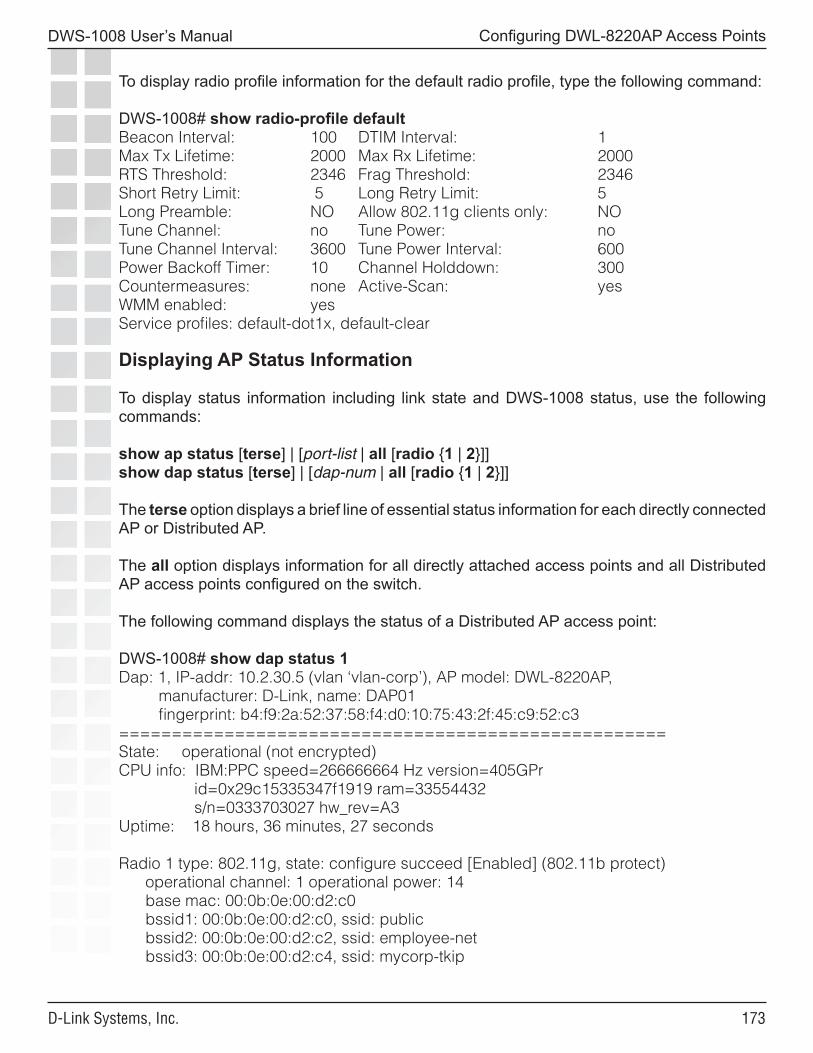
���
DWS-1008 User’s Manual
D-Link Systems, Inc.
Configuring DWL-8220AP Access Points
To display radio profile information for the default radio profile, type the following command:
DWS-1008# show radio-profile defaultBeacon Interval: 100 DTIM Interval: 1Max Tx Lifetime: 2000 Max Rx Lifetime: 2000RTS Threshold: 2346 Frag Threshold: 2346Short Retry Limit: 5 Long Retry Limit: 5Long Preamble: NO Allow 802.11g clients only: NOTune Channel: no Tune Power: noTune Channel Interval: 3600 Tune Power Interval: 600Power Backoff Timer: 10 Channel Holddown: 300Countermeasures: none Active-Scan: yesWMM enabled: yesService profiles: default-dot1x, default-clear
Displaying AP Status Information
To display status information including link state and DWS-1008 status, use the following commands:
show ap status [terse] | [port-list | all [radio {1 | 2}]]show dap status [terse] | [dap-num | all [radio {1 | 2}]]
The terse option displays a brief line of essential status information for each directly connected AP or Distributed AP.
The all option displays information for all directly attached access points and all Distributed AP access points configured on the switch.
The following command displays the status of a Distributed AP access point:
DWS-1008# show dap status 1Dap: 1, IP-addr: 10.2.30.5 (vlan ‘vlan-corp’), AP model: DWL-8220AP, manufacturer: D-Link, name: DAP01 fingerprint: b4:f9:2a:52:37:58:f4:d0:10:75:43:2f:45:c9:52:c3====================================================State: operational (not encrypted)CPU info: IBM:PPC speed=266666664 Hz version=405GPr id=0x29c15335347f1919 ram=33554432 s/n=0333703027 hw_rev=A3Uptime: 18 hours, 36 minutes, 27 seconds
Radio 1 type: 802.11g, state: configure succeed [Enabled] (802.11b protect) operational channel: 1 operational power: 14 base mac: 00:0b:0e:00:d2:c0 bssid1: 00:0b:0e:00:d2:c0, ssid: public bssid2: 00:0b:0e:00:d2:c2, ssid: employee-net bssid3: 00:0b:0e:00:d2:c4, ssid: mycorp-tkip
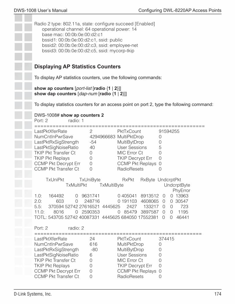
���
DWS-1008 User’s Manual
D-Link Systems, Inc.
Configuring DWL-8220AP Access Points
Radio 2 type: 802.11a, state: configure succeed [Enabled] operational channel: 64 operational power: 14 base mac: 00:0b:0e:00:d2:c1 bssid1: 00:0b:0e:00:d2:c1, ssid: public bssid2: 00:0b:0e:00:d2:c3, ssid: employee-net bssid3: 00:0b:0e:00:d2:c5, ssid: mycorp-tkip
Displaying AP Statistics Counters
To display AP statistics counters, use the following commands:
show ap counters [port-list [radio {1 | 2}]]show dap counters [dap-num [radio {1 | 2}]]
To display statistics counters for an access point on port 2, type the following command:
DWS-1008# show ap counters 2Port: 2 radio: 1========================================================LastPktXferRate 2 PktTxCount 91594255NumCntInPwrSave 4294966683 MultiPktDrop 0LastPktRxSigStrength -54 MultiBytDrop 0LastPktSigNoiseRatio 40 User Sessions 5TKIP Pkt Transfer Ct 0 MIC Error Ct 0TKIP Pkt Replays 0 TKIP Decrypt Err 0CCMP Pkt Decrypt Err 0 CCMP Pkt Replays 0CCMP Pkt Transfer Ct 0 RadioResets 0
TxUniPkt TxUniByte RxPkt RxByte UndcrptPkt TxMultiPkt TxMultiByte UndcrptByte PhyError1.0: 164492 0 9631741 0 405041 8913512 0 0 139632.0: 603 0 248716 0 191103 4608065 0 0 305475.5: 370594 52742 27616521 4445625 2427 133217 0 0 72311.0: 8016 0 2590353 0 85479 3897587 0 0 1195TOTL: 543705 52742 40087331 4445625 684050 17552381 0 0 46441
Port: 2 radio: 2=======================================================LastPktXferRate 24 PktTxCount 374415NumCntInPwrSave 616 MultiPktDrop 0LastPktRxSigStrength -80 MultiBytDrop 0LastPktSigNoiseRatio 6 User Sessions 0TKIP Pkt Transfer Ct 0 MIC Error Ct 0TKIP Pkt Replays 0 TKIP Decrypt Err 0CCMP Pkt Decrypt Err 0 CCMP Pkt Replays 0CCMP Pkt Transfer Ct 0 RadioResets 0
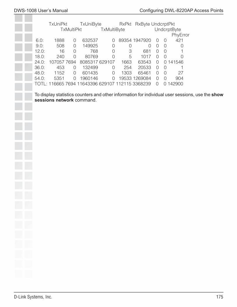
���
DWS-1008 User’s Manual
D-Link Systems, Inc.
Configuring DWL-8220AP Access Points
TxUniPkt TxUniByte RxPkt RxByte UndcrptPkt TxMultiPkt TxMultiByte UndcrptByte PhyError 6.0: 1888 0 632537 0 89354 1947920 0 0 421 9.0: 508 0 149925 0 0 0 0 0 012.0: 16 0 768 0 3 681 0 0 118.0: 240 0 80769 0 5 1017 0 0 024.0: 107057 7694 8085317 629107 1663 63543 0 0 14154636.0: 453 0 132499 0 254 20533 0 0 148.0: 1152 0 601435 0 1303 65461 0 0 2754.0: 5351 0 1960146 0 19533 1269084 0 0 904TOTL: 116665 7694 11643396 629107 112115 3368239 0 0 142900
To display statistics counters and other information for individual user sessions, use the show sessions network command.
���
DWS-1008 User’s Manual
D-Link Systems, Inc.
Configuring User Encryption
Configuring User EncryptionMobility System Software (MSS) encrypts wireless user traffic for all users who are successfully authenticated to join an encrypted SSID and who are then authorized to join a VLAN. MSS supports the following types of encryption for wireless user traffic:
• 802.11i• Wi-Fi Protected Access (WPA)• Non-WPA dynamic Wired Equivalent Privacy (WEP)• Non-WPA static WEP
WEP is described in the IEEE 802.11 standard and WPA is described in the 802.11i standard.
WPA and 802.11i provide stronger security than WEP. (802.11i uses Robust Security Network (RSN), and is sometimes called WPA2.)
To use WPA or RSN, a client must support it. For non-WPA clients, MSS supports WEP. If your network contains a combination of WPA, RSN, clients and non-WPA clients, you can configure MSS to provide encryption for both types of clients.
To configure encryption parameters for an SSID, create or edit a service profile, map the service profile to a radio profile, and add radios to the radio profile. The SSID name, advertisement setting (beaconing), and encryption settings are configured in the service profile.
You can configure an SSID to support any combination of WPA, RSN, and non-WPA clients. For example, a radio can simultaneously use Temporal Key Integrity Protocol (TKIP) encryption for WPA clients and WEP encryption for non-WPA clients.
The SSID type must be crypto (encrypted) for encryption to be used. If the SSID type is clear, wireless traffic is not encrypted, regardless of the encryption settings.
Note: MSS does not encrypt traffic in the wired part of the network. MSS does not encrypt wireless or wired traffic for users who associate with an unencrypted (clear) SSID.
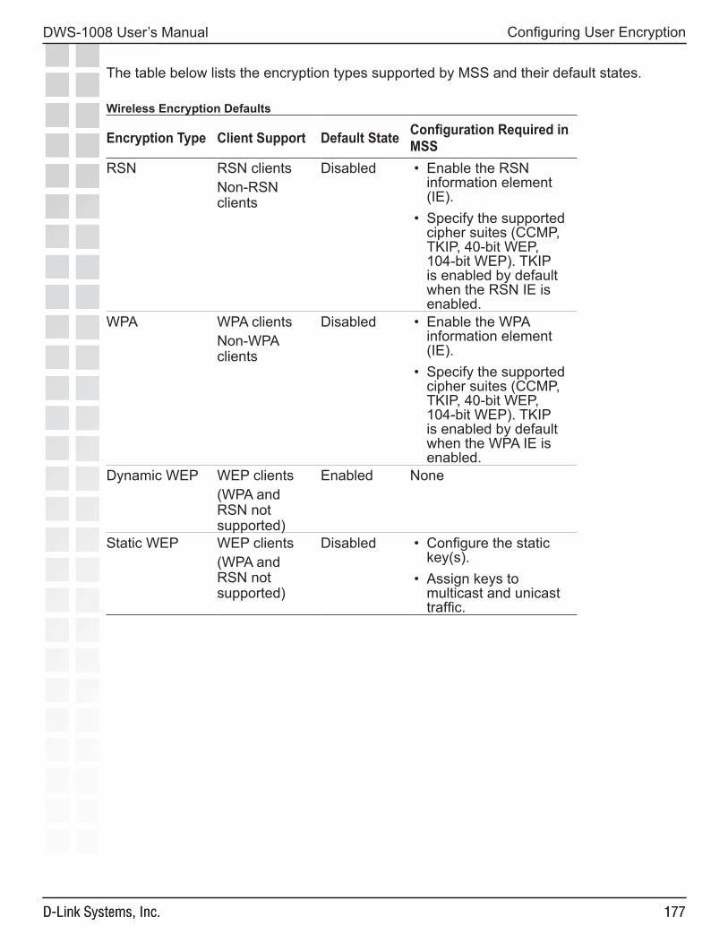
���
DWS-1008 User’s Manual
D-Link Systems, Inc.
Configuring User Encryption
���D-Link Systems, Inc.
The table below lists the encryption types supported by MSS and their default states.
Wireless Encryption Defaults
Encryption Type Client Support Default State Configuration Required in MSS
RSN RSN clientsNon-RSN clients
Disabled • Enable the RSN information element (IE).
• Specify the supported cipher suites (CCMP, TKIP, 40-bit WEP, 104-bit WEP). TKIP is enabled by default when the RSN IE is enabled.
WPA WPA clientsNon-WPA clients
Disabled • Enable the WPA information element (IE).
• Specify the supported cipher suites (CCMP, TKIP, 40-bit WEP, 104-bit WEP). TKIP is enabled by default when the WPA IE is enabled.
Dynamic WEP WEP clients(WPA and RSN not supported)
Enabled None
Static WEP WEP clients(WPA and RSN not supported)
Disabled • Configure the static key(s).
• Assign keys to multicast and unicast traffic.
���
DWS-1008 User’s Manual
D-Link Systems, Inc.
Configuring User Encryption
���D-Link Systems, Inc.
Configuring WPA
Wi-Fi Protected Access (WPA) is a security enhancement to the IEEE 802.11 wireless standard. WPA provides enhanced encryption with new cipher suites and provides per-packet message integrity checks. WPA is based on the 802.11i standard. You can use WPA with 802.1X authentication. If the client does not support 802.1X, you can use a preshared key on the DWL-8200AP access point and the client for authentication.
WPA Cipher Suites
WPA supports the following cipher suites for packet encryption, listed from most secure to least secure:
• Counter Mode with Cipher Block Chaining Message Authentication Code Protocol (CCMP) - CCMP provides Advanced Encryption Standard (AES) data encryption. To provide message integrity, CCMP uses the Cipher Block Chaining Message Authentication Code (CBC-MAC).
• Temporal Key Integrity Protocol (TKIP) - TKIP uses the RC4 encryption algorithm, a 128-bit encryption key, a 48-bit initialization vector (IV), and a message integrity code (MIC) called Michael.
• Wired Equivalent Privacy (WEP) with 104-bit keys - 104-bit WEP uses the RC4 encryption algorithm with a 104-bit key.
• WEP with 40-bit keys - 40-bit WEP uses the RC4 encryption algorithm with a 40-bit key.
You can configure DWL-8200AP access points to support one or more of these cipher suites. For all of these cipher suites, MSS dynamically generates unique session keys for each session. MSS periodically changes the keys to reduce the likelihood that a network intruder can intercept enough frames to decode a key.
TKIP Countermeasures
WPA access points and clients verify the integrity of a wireless frame received on the network by generating a keyed message integrity check (MIC). The Michael MIC used with TKIP provides a holddown mechanism to protect the network against tampering.
• If the recalculated MIC matches the MIC received with the frame, the frame passes the integrity check and the access point or client processes the frame normally.
���
DWS-1008 User’s Manual
D-Link Systems, Inc.
Configuring User Encryption
���D-Link Systems, Inc.
• If the recalculated MIC does not match the MIC received with the frame, the frame fails the integrity check. This condition is called a MIC failure. The access point or client discards the frame and also starts a 60-second timer. If another MIC failure does not occur within 60 seconds, the timer expires. However, if another MIC failure occurs before the timer expires, the device takes the following actions:
• An DWL-8200AP access point that receives another frame with an invalid MIC ends its sessions with all TKIP and WEP clients by disassociating from the clients. This includes both WPA WEP clients and non-WPA WEP clients. The access point also temporarily shuts down the network by refusing all association or reassociation requests from TKIP and WEP clients. In addition, MSS generates an SNMP trap that indicates the swich port and radio that received frames with the two MIC failures as well as the source and destination MAC addresses in the frames.
• A client that receives another frame with an invalid MIC disassociates from its access point and does not send or accept any frames encrypted with TKIP or WEP.
The DWL-8200AP access point or client refuses to send or receive traffic encrypted with TKIP or WEP for the duration of the countermeasures timer, which is 60,000 milliseconds (60 seconds) by default. When the countermeasures timer expires, the access point allows associations and reassociations and generates new session keys for them. You can set the countermeasures timer for DWL-8200AP access point radios to a value from 0 to 60,000 milliseconds (ms). If you specify 0 ms, the radios do not use countermeasures but instead continue to accept and forward encrypted traffic following a second MIC failure. However, MSS still generates an SNMP trap to inform you of the MIC failure.
The MIC used by CCMP, CBC-MAC, is even stronger than Michael and does not require or provide countermeasures. WEP does not use a MIC. Instead, WEP performs a cyclic redundancy check (CRC) on the frame and generates an integrity check value (ICV).
WPA Authentication Methods
You can configure an SSID to support one or both of the following authentication methods for WPA clients:
• 802.1X - The DWL-8200AP access point and client use an Extensible Authentication Protocol (EAP) method to authenticate one another, then use the resulting key in a handshake to derive a unique key for the session. The 802.1X authentication method requires user information to be configured on AAA servers or in the switch’s local database. This is the default WPA authentication method.
• Preshared key (PSK) - An DWL-8200AP radio and a client authenticate one another based on a key that is statically configured on both devices. The devices then use the key in a handshake to derive a unique key for the session. For a given service profile, you can globally configure a PSK for use with all clients. You can configure the key by entering an ASCII passphrase or by entering the key itself in raw (hexadecimal) form.
��0
DWS-1008 User’s Manual
D-Link Systems, Inc.
Configuring User Encryption
��0D-Link Systems, Inc.
Note: For a MAC client that authenticates using a PSK, the RADIUS servers or local database still must contain an authentication rule for the client, to assign the client to a VLAN.
WPA Information Element
A WPA information element (IE) is a set of extra fields in a wireless frame that contain WPA information for the access point or client. To enable WPA support in a service profile, you must enable the WPA IE. The following types of wireless frames can contain a WPA IE:
• Beacon (sent by a DWL-8200AP access point) - The WPA IE in a beacon frame advertises the cipher suites and authentication methods that a DWL-8200AP radio supports for the encrypted SSID. The WPA IE also lists the cipher suites that the radio uses to encrypt broadcast and multicast frames. A DWL-8200AP radio always uses the least secure of the cipher suites to encrypt broadcast and multicast frames to ensure that all clients associated with the SSID can decrypt the frames. A DWL-8200AP radio uses the most secure cipher suite supported by both the radio and a client to encrypt unicast traffic to that client.
• Probe response (sent by a DWL-8200AP radio) - The WPA IE in a probe response frame lists the same WPA information that is contained in the beacon frame.
• Association request or reassociation (sent by a client) - The WPA IE in an association request lists the authentication method and cipher suite the client wants to use.
Client Support
To use the TKIP or CCMP cipher suite for encryption, a client must support WPA. However, a DWL-8200AP radio configured for WPA can support non-WPA clients who use dynamic WEP or static WEP. If the WPA IE is enabled in the service profile used by an SSID supported by the radio, and the 40-bit WEP or 104-bit WEP cipher suite also is enabled in the service profile, MSS allows a non-WPA client to authenticate using WEP under the following circumstances:
• If a client wants to authenticate using dynamic WEP, MSS uses 802.1X to authenticate the client if either the WEP40 or WEP104 cipher suite is enabled for WPA.
• If a client wants to authenticate using static WEP, the radio checks for the static WEP key presented by the client. If the keys match, MSS authenticates the client. Because the WEP key is static, MSS does not use 802.1X to authenticate the client.
To allow a non-WPA client that uses dynamic WEP to be authenticated by a radio on which WPA IE is enabled, enable the WEP40 or WEP104 cipher suite in the service profile for the SSID the client will access. To prevent non-WPA clients that use dynamic WEP from being authenticated, do not enable the WEP40 or WEP104 cipher suite in the service profile.
To allow a client that uses static WEP to be authenticated, configure the same WEP keys on the client and the service profile.
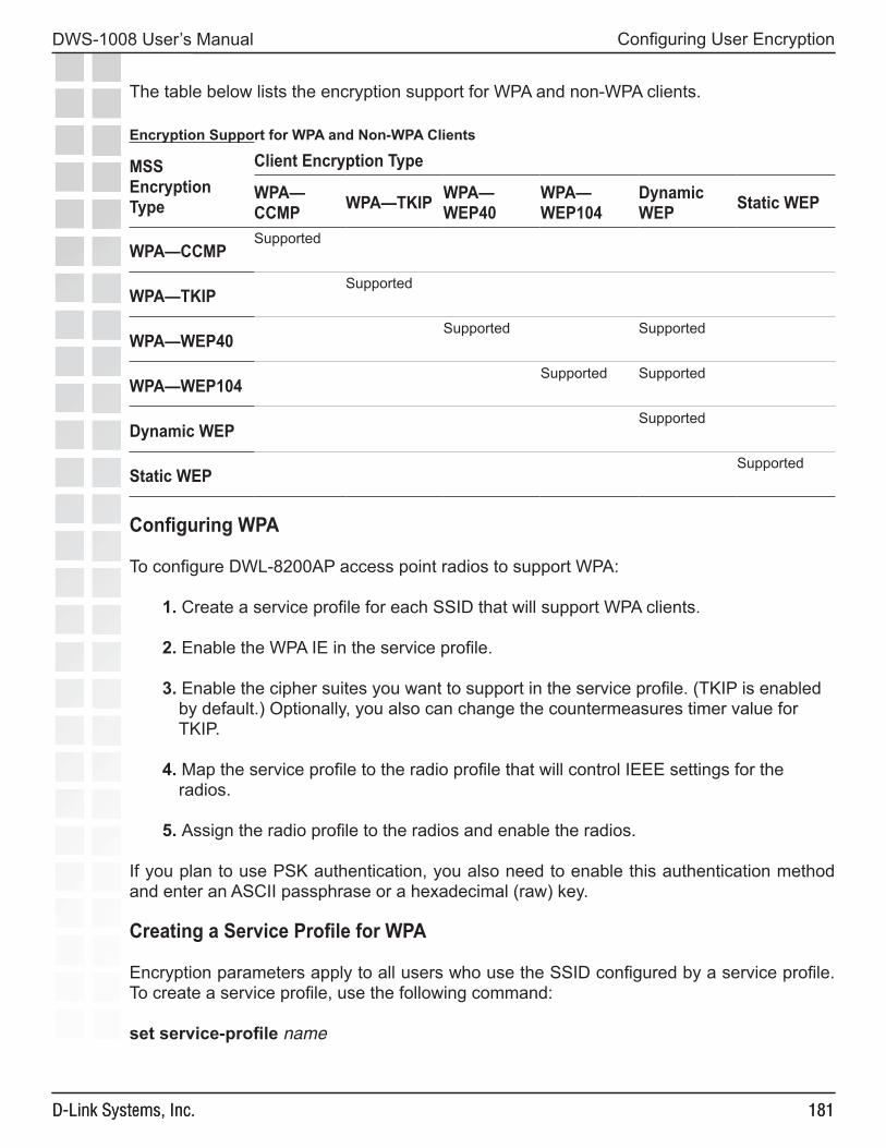
���
DWS-1008 User’s Manual
D-Link Systems, Inc.
Configuring User Encryption
���D-Link Systems, Inc.
The table below lists the encryption support for WPA and non-WPA clients.
Encryption Support for WPA and Non-WPA Clients
MSS Encryption Type
Client Encryption Type
WPA—CCMP WPA—TKIP WPA—
WEP40WPA—WEP104
Dynamic WEP Static WEP
WPA—CCMPSupported
WPA—TKIPSupported
WPA—WEP40Supported Supported
WPA—WEP104Supported Supported
Dynamic WEPSupported
Static WEPSupported
Configuring WPA
To configure DWL-8200AP access point radios to support WPA:
1. Create a service profile for each SSID that will support WPA clients.
2. Enable the WPA IE in the service profile.
3. Enable the cipher suites you want to support in the service profile. (TKIP is enabled by default.) Optionally, you also can change the countermeasures timer value for TKIP.
4. Map the service profile to the radio profile that will control IEEE settings for the radios.
5. Assign the radio profile to the radios and enable the radios.
If you plan to use PSK authentication, you also need to enable this authentication method and enter an ASCII passphrase or a hexadecimal (raw) key.
Creating a Service Profile for WPA
Encryption parameters apply to all users who use the SSID configured by a service profile. To create a service profile, use the following command:
set service-profile name
���
DWS-1008 User’s Manual
D-Link Systems, Inc.
Configuring User Encryption
���D-Link Systems, Inc.
To create a new service profile named wpa, type the following command:
DWS-1008# set service-profile wpasuccess: change accepted.
Enabling WPA
To enable WPA, you must enable the WPA information element (IE) in the service profile. To enable the WPA IE, use the following command:
set service-profile name wpa-ie {enable | disable}
To enable WPA in service profile wpa, type the following command:
DWS-1008# set service-profile wpa wpa-ie enablesuccess: change accepted.
Specifying the WPA Cipher Suites
To use WPA, at least one cipher suite must be enabled. You can enable one or more of the following cipher suites:
• CCMP• TKIP• 40-bit WEP• 104-bit WEP
By default, TKIP is enabled and the other cipher suites are disabled.
To enable or disable cipher suites, use the following commands:
set service-profile name cipher-ccmp {enable | disable}set service-profile name cipher-tkip {enable | disable}set service-profile name cipher-wep104 {enable | disable}set service-profile name cipher-wep40 {enable | disable}
To enable the 40-bit WEP cipher suite in service profile wpa, type the following command:
DWS-1008# set service-profile wpa cipher-wep40 enablesuccess: change accepted.
After you type this command, the service profile supports TKIP and 40-bit WEP.
Changing the TKIP Countermeasures Timer Value
By default, MSS enforces TKIP countermeasures for 60,000 ms (60 seconds) after a second MIC failure within a one-minute interval. To change the countermeasures timer value, use the following command:
���
DWS-1008 User’s Manual
D-Link Systems, Inc.
Configuring User Encryption
���D-Link Systems, Inc.
set service-profile name tkip-mc-time wait-timeTo change the countermeasures wait time in service profile wpa to 30 seconds, type the following command:
DWS-1008# set service-profile wpa tkip-mc-time 30000success: change accepted.
Enabling PSK Authentication
By default, WPA uses 802.1X dynamic keying. If you plan to use static keys, you must enable PSK authentication and configure a passphrase or the raw key. You can configure the passphrase or key globally. You also can configure keys on an individual MAC client basis.
By default, 802.1X authentication remains enabled when you enable PSK authentication.
To enable PSK authentication, use the following command:
set service-profile name auth-psk {enable | disable}
To enable PSK authentication in service profile wpa, type the following command:
DWS-1008# set service-profile wpa auth-psk enablesuccess: change accepted.
Configuring a Global PSK Passphrase or Raw Key for All Clients
To configure a global passphrase for all WPA clients, use the following command:
set service-profile name psk-phrase passphrase
The passphrase must be exactly 63 characters long, including blanks. If you use blanks, you must enclose the string in quotation marks.
To configure service profile wpa to use passphrase 1234567890123<>?=+&% The quick brown fox jumps over the lazy sl, type the following command:
DWS-1008# set service-profile wpa psk-phrase “1234567890123<>?=+&% The quick brown fox jumps over the lazy sl”success: change accepted.
As an alternative to entering a passphrase, which MSS converts into a key, you can enter the key itself in raw hexadecimal format. To enter a PSK key in raw format, use the following command:
set service-profile name psk-raw hex
For hex, type a 64-bit ASCII string representing a 32-digit hexadecimal number. Enter the two-character ASCII form of each hexadecimal number.
���
DWS-1008 User’s Manual
D-Link Systems, Inc.
Configuring User Encryption
���D-Link Systems, Inc.
Examples: To configure service profile wpa to use a raw PSK with PSK clients, type a command such as the following:
DWS-1008# set service-profile wpa psk-raw c25d3fe4483e867d1df96eaacdf8b02451fa0836162e758100f5f6b87965e59dsuccess: change accepted.
Disabling 802.1X Authentication for WPA
To disable 802.1X authentication for WPA clients, use the following command:set service-profile name auth-dot1x {enable | disable}
Note: This command does not disable 802.1X authentication for non-WPA clients.
To disable WPA authentication in service profile wpa, type the following command:
DWS-1008# set service-profile wpa auth-dot1x disablesuccess: change accepted.
Displaying WPA Settings
To display the WPA settings in a service profile, use the following command:
show service-profile {name | ?}
To display the WPA settings in effect in service profile wpa, type the following command:
DWS-1008# show service-profile wpassid-name: private ssid-type: cryptobeacon: yes auth-fallthru: noneWEP Key 1 value: <none> WEP Key 2 value: <none>WEP Key 3 value: <none> WEP Key 4 value: <none>WEP Unicast Index: 1 WEP Multicast Index: 1Shared Key Auth: NOWPA enabled: ciphers: cipher-tkip, cipher-wep40 authentication: 802.1X TKIP countermeasures time: 30000ms
The WPA settings appear at the bottom of the output.
Note: The WPA fields appear in the show service-profile output only when WPA is enabled.
���
DWS-1008 User’s Manual
D-Link Systems, Inc.
Configuring User Encryption
���D-Link Systems, Inc.
Assigning the Service Profile to Radios and Enabling the Radios
After you configure WPA settings in a service profile, you can map the service profile to a radio profile, assign the radio profile to radios, and enable the radios to activate the settings. To map a service profile to a radio profile, use the following command:
set radio-profile name service-profile name
To assign a radio profile to radios and enable the radios, use the following command:
set ap port-list radio {1 | 2} radio-profile name mode {enable | disable}
To map service profile wpa to radio profile bldg1, type the following command:
DWS-1008# set radio-profile blgd1 service-profile wpasuccess: change accepted.
To assign radio profile bldg1 to radio 1 on ports 1-3, and 6 and enable the radios, type the following command:
DWS-1008# set ap 1-3,6 radio 1 radio-profile bldg1 mode enablesuccess: change accepted.
To assign radio profile bldg1 to radio 2 on ports 4-5 and enable the radios, type the following command:
DWS-1008# set ap 4-5 radio 2 radio-profile bldg1 mode enablesuccess: change accepted.
Configuring RSN (802.11i)Robust Security Network (RSN) provides 802.11i support. RSN uses AES encryption.
You can configure a service profile to support RSN clients exclusively, or to support RSN with WPA clients, or even RSN, WPA and WEP clients.
The configuration tasks for a service profile to use RSN are similar to the tasks for WPA:
1. Create a service profile for each SSID that will support RSN clients.
2. Enable the RSN IE in the service profile.
3. Enable the cipher suites you want to support in the service profile. (TKIP is enabled by default.) Optionally, you also can change the countermeasures timer value for TKIP.
4. Map the service profile to the radio profile that will control IEEE settings for the radios.
5. Assign the radio profile to the radios and enable the radios.
���
DWS-1008 User’s Manual
D-Link Systems, Inc.
Configuring User Encryption
���D-Link Systems, Inc.
If you plan to use PSK authentication, you also need to enable this authentication method and enter an ASCII passphrase or a hexadecimal (raw) key.
Creating a Service Profile for RSN
Encryption parameters apply to all users who use the SSID configured by a service profile. To create a service profile, use the following command:
set service-profile name
To create a new service profile named rsn, type the following command:
DWS-1008# set service-profile rsnsuccess: change accepted.
Enabling RSN
To enable RSN, you must enable the RSN information element (IE) in the service profile. To enable the RSN IE, use the following command:
set service-profile name rsn-ie {enable | disable}
To enable RSN in service profile wpa, type the following command:
DWS-1008# set service-profile rsn rsn-ie enablesuccess: change accepted.
Specifying the RSN Cipher Suites
To use RSN, at least one cipher suite must be enabled. You can enable one or more of the following cipher suites:
• CCMP• TKIP• 40-bit WEP• 104-bit WEP
By default, TKIP is enabled and the other cipher suites are disabled. To enable or disable cipher suites, use the following commands:
set service-profile name cipher-ccmp {enable | disable}set service-profile name cipher-tkip {enable | disable}set service-profile name cipher-wep104 {enable | disable}set service-profile name cipher-wep40 {enable | disable}
To enable the CCMP cipher suite in service profile rsn, type the following command:
DWS-1008# set service-profile rsn cipher-ccmp enablesuccess: change accepted.
���
DWS-1008 User’s Manual
D-Link Systems, Inc.
Configuring User Encryption
���D-Link Systems, Inc.
After you type this command, the service profile supports both TKIP and CCMP.
Displaying RSN Settings
To display the RSN settings in a service profile, use the following command:
show service-profile {name | ?}
The RSN settings appear at the bottom of the output.
Note. The RSN-related fields appear in the show service-profile output only when RSN is enabled.
Assigning the Service Profile to Radios and Enabling the Radios
After you configure RSN settings in a service profile, you can map the service profile to a radio profile, assign the radio profile to radios, and enable the radios to activate the settings. To map a service profile to a radio profile, use the following command:
set radio-profile name service-profile name
To assign a radio profile to radios and enable the radios, use the following command:
set ap port-list radio {1 | 2} radio-profile name mode {enable | disable}To map service profile rsn to radio profile bldg2, type the following command:
DWS-1008# set radio-profile blgd2 service-profile rsnsuccess: change accepted.
���
DWS-1008 User’s Manual
D-Link Systems, Inc.
Configuring User Encryption
���D-Link Systems, Inc.
Configuring WEP
Wired-Equivalent Privacy (WEP) is a security protocol defined in the 802.11 standard. WEP uses the RC4 encryption algorithm to encrypt data.
To provide integrity checking, WEP access points and clients check the integrity of a frame’s cyclic redundancy check (CRC), generate an integrity check value (ICV), and append the value to the frame before sending it. The radio or client that receives the frame recalculates the ICV and compares the result to the ICV in the frame. If the values match, the frame is processed. If the values do not match, the frame is discarded.
WEP is either dynamic or static depending on how the encryption keys are generated. DWL-8200AP access points support dynamic WEP and static WEP.
• For dynamic WEP, MSS dynamically generates keys for broadcast, multicast, and unicast traffic. MSS generates unique unicast keys for each client session and periodically regenerates (rotates) the broadcast and multicast keys for all clients. You can change or disable the broadcast or multicast rekeying interval.
• For static WEP, MSS uses statically configured keys typed in the switch’s configuration and on the wireless client and does not rotate the keys.
Dynamic WEP encryption is enabled by default. You can disable dynamic WEP support by enabling WPA and leaving the WEP-40 or WEP-104 cipher suites disabled. If you use dynamic WEP, 802.1X must also be configured on the client in addition to WEP.
Static WEP encryption is disabled by default. To enable static WEP encryption, configure the static WEP keys and assign them to unicast and multicast traffic. Make sure you configure the same static keys on the clients.
Setting Static WEP Key Values
MSS supports dynamic WEP automatically. To enable static WEP, configure WEP keys and assign them to unicast and multicast traffic. You can set the values of the four static WEP keys, then specify which of the keys to use for encrypting multicast frames and unicast frames. If you do this, MSS continues to support dynamic WEP in addition to static WEP.
To set the value of a WEP key, use the following command:
set service-profile name wep key-index num key value
The key-index num parameter specifies the index you are configuring. You can specify a value from 1 through 4.
���
DWS-1008 User’s Manual
D-Link Systems, Inc.
Configuring User Encryption
���D-Link Systems, Inc.
The key value parameter specifies the hexadecimal value of the key. Type a 10-character ASCII string (representing a 5-digit hexadecimal number) or type a 26-character ASCII string (representing a 13-digit hexadecimal number). You can use numbers or letters. ASCII characters in the following ranges are supported:
• 0 to 9• A to F• a to f
To configure WEP key index 1 for radio profile rp1 to aabbccddee, type the following command:
DWS-1008# set service-profile rp1 wep key-index 1 key aabbccddeesuccess: change accepted.
Assigning Static WEP Keys
When static WEP is enabled, static WEP key 1 is assigned to unicast and multicast traffic by default. To assign another key to unicast or multicast traffic, use the following commands:
set service-profile name wep active-multicast-index numset service-profile name wep active-unicast-index num
The num parameter specifies the key and the value can be from 1 to 4.
To configure an SSID that uses service profile wepsrvc to use WEP key index 2 for encrypting multicast traffic, type the following command:
DWS-1008# set service-profile wepsrvc wep active-multicast-index 2success: change accepted.
To configure an SSID that uses service profile wepsrvc4 to use WEP key index 4 for encrypting unicast traffic, type the following command:
DWS-1008# set service-profile wepsrvc4 wep active-unicast-index 4success: change accepted.
��0
DWS-1008 User’s Manual
D-Link Systems, Inc.
Configuring User Encryption
��0D-Link Systems, Inc.
Encryption Configuration Scenarios
The following scenarios provide examples of ways in which you can configure encryption for network clients:
Enabling WPA with TKIP
The following example shows how to configure MSS to provide authentication and TKIP encryption for 801.X WPA clients. This example assumes that pass-through authentication is used for all users. A RADIUS server group performs all authentication and authorization for the users.
1. Create an authentication rule that sends all 802.1X users of SSID mycorp in the EXAMPLE domain to the server group shorebirds for authentication. Type the following command:
DWS-1008# set authentication dot1x ssid mycorp EXAMPLE\* pass-through shorebirds
2. Create a service profile named wpa for the SSID. Type the following command:
DWS-1008# set service-profile wpasuccess: change accepted.
3. Set the SSID in the service profile to mycorp. Type the following command:
DWS-1008# set service-profile wpa ssid-name wpasuccess: change accepted.
4. Enable WPA in service profile wpa. Type the following command:
DWS-1008# set service-profile wpa wpa-ie enablesuccess: change accepted.
TKIP is already enabled by default when WPA is enabled.
5. Display the service profile wpa to verify the changes. Type the following command:
DWS-1008# show service-profile wpassid-name: mycorp ssid-type: cryptobeacon: yes auth-fallthru: noneWEP Key 1 value: <none> WEP Key 2 value: <none>WEP Key 3 value: <none> WEP Key 4 value: <none>WEP Unicast Index: 1 WEP Multicast Index: 1Shared Key Auth: NOWPA enabled: ciphers: cipher-tkip authentication: 802.1X TKIP countermeasures time: 60000ms

���
DWS-1008 User’s Manual
D-Link Systems, Inc.
Configuring User Encryption
���D-Link Systems, Inc.
6. Map service profile wpa to radio profile rp1. Type the following commands:
DWS-1008# set radio-profile rp1 service-profile wpasuccess: change accepted.
7. Apply radio profile rp1 to radio 1 on port 5 and to radios 1 and 2 on port 6, enable the radios, and verify the configuration changes. Type the following commands:
DWS-1008# set ap 5,6 radio 1 radio-profile rp1 mode enablesuccess: change accepted.
DWS-1008# set ap 6 radio 2 radio-profile rp1 mode enablesuccess: change accepted.
DWS-1008# show ap configPort 5: AP model: DWL-8220AP, POE: enable, bias: high, name: AP05 boot-download-enable: YES load balancing group: none Radio 1: type: 802.11a, mode: enabled, channel: 36 tx pwr: 1, profile: rp1 auto-tune max-power: default, min-client-rate: 5.5, max-retransmissions: 10Port 11: AP model: DWL-8220AP, POE: enable, bias: high, name: AP6 boot-download-enable: YES load balancing group: none Radio 1: type: 802.11g, mode: enabled, channel: 6 tx pwr: 1, profile: rp1 auto-tune max-power: default, min-client-rate: 5.5, max-retransmissions: 10 Radio 2: type: 802.11a, mode: enabled, channel: 36 tx pwr: 1, profile: rp1 auto-tune max-power: default, min-client-rate: 24, max-retransmissions: 10
8. Save the configuration. Type the following command:
DWS-1008# save configsuccess: configuration saved.
Enabling Dynamic WEP in a WPA Network
The following example shows how to configure MSS to provide authentication and encryption for 801.X dynamic WEP clients, and for 801.X WPA clients using TKIP. This example assumes that pass-through authentication is used for all users. The WEP cipher suite allows authentication and encryption for both WPA and non-WPA clients that want to authenticate using dynamic WEP.
1. Create an authentication rule that sends all 802.1X users of SSID mycorp in the EXAMPLE domain to the server group shorebirds for authentication. Type the following command:
DWS-1008# set authentication dot1x ssid thiscorp EXAMPLE\* pass-through shorebirds
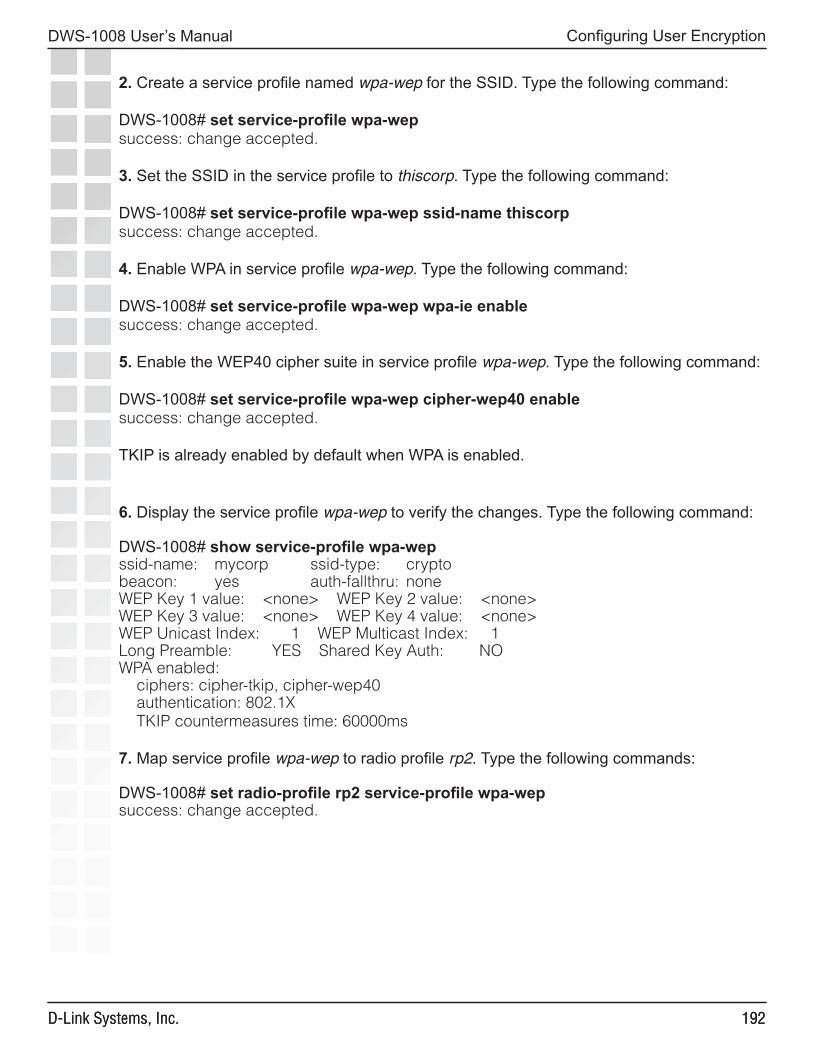
���
DWS-1008 User’s Manual
D-Link Systems, Inc.
Configuring User Encryption
���D-Link Systems, Inc.
2. Create a service profile named wpa-wep for the SSID. Type the following command:
DWS-1008# set service-profile wpa-wepsuccess: change accepted.
3. Set the SSID in the service profile to thiscorp. Type the following command:
DWS-1008# set service-profile wpa-wep ssid-name thiscorpsuccess: change accepted.
4. Enable WPA in service profile wpa-wep. Type the following command:
DWS-1008# set service-profile wpa-wep wpa-ie enablesuccess: change accepted.
5. Enable the WEP40 cipher suite in service profile wpa-wep. Type the following command:
DWS-1008# set service-profile wpa-wep cipher-wep40 enablesuccess: change accepted.
TKIP is already enabled by default when WPA is enabled.
6. Display the service profile wpa-wep to verify the changes. Type the following command:
DWS-1008# show service-profile wpa-wepssid-name: mycorp ssid-type: cryptobeacon: yes auth-fallthru: noneWEP Key 1 value: <none> WEP Key 2 value: <none>WEP Key 3 value: <none> WEP Key 4 value: <none>WEP Unicast Index: 1 WEP Multicast Index: 1Long Preamble: YES Shared Key Auth: NOWPA enabled: ciphers: cipher-tkip, cipher-wep40 authentication: 802.1X TKIP countermeasures time: 60000ms
7. Map service profile wpa-wep to radio profile rp2. Type the following commands:
DWS-1008# set radio-profile rp2 service-profile wpa-wepsuccess: change accepted.
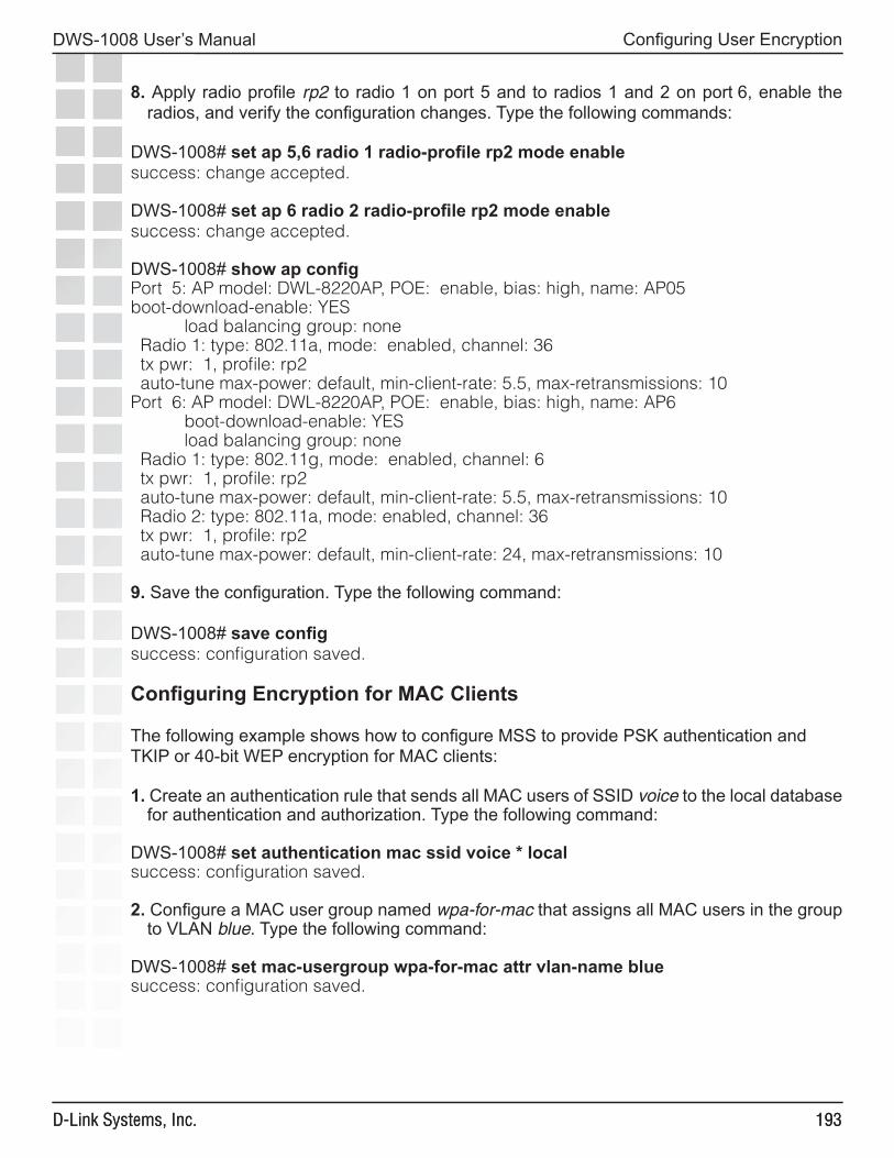
���
DWS-1008 User’s Manual
D-Link Systems, Inc.
Configuring User Encryption
���D-Link Systems, Inc.
8. Apply radio profile rp2 to radio 1 on port 5 and to radios 1 and 2 on port 6, enable the radios, and verify the configuration changes. Type the following commands:
DWS-1008# set ap 5,6 radio 1 radio-profile rp2 mode enablesuccess: change accepted.
DWS-1008# set ap 6 radio 2 radio-profile rp2 mode enablesuccess: change accepted.
DWS-1008# show ap configPort 5: AP model: DWL-8220AP, POE: enable, bias: high, name: AP05boot-download-enable: YES load balancing group: none Radio 1: type: 802.11a, mode: enabled, channel: 36 tx pwr: 1, profile: rp2 auto-tune max-power: default, min-client-rate: 5.5, max-retransmissions: 10Port 6: AP model: DWL-8220AP, POE: enable, bias: high, name: AP6 boot-download-enable: YES load balancing group: none Radio 1: type: 802.11g, mode: enabled, channel: 6 tx pwr: 1, profile: rp2 auto-tune max-power: default, min-client-rate: 5.5, max-retransmissions: 10 Radio 2: type: 802.11a, mode: enabled, channel: 36 tx pwr: 1, profile: rp2 auto-tune max-power: default, min-client-rate: 24, max-retransmissions: 10
9. Save the configuration. Type the following command:
DWS-1008# save configsuccess: configuration saved.
Configuring Encryption for MAC Clients
The following example shows how to configure MSS to provide PSK authentication and TKIP or 40-bit WEP encryption for MAC clients:
1. Create an authentication rule that sends all MAC users of SSID voice to the local database for authentication and authorization. Type the following command:
DWS-1008# set authentication mac ssid voice * localsuccess: configuration saved.
2. Configure a MAC user group named wpa-for-mac that assigns all MAC users in the group to VLAN blue. Type the following command:
DWS-1008# set mac-usergroup wpa-for-mac attr vlan-name bluesuccess: configuration saved.
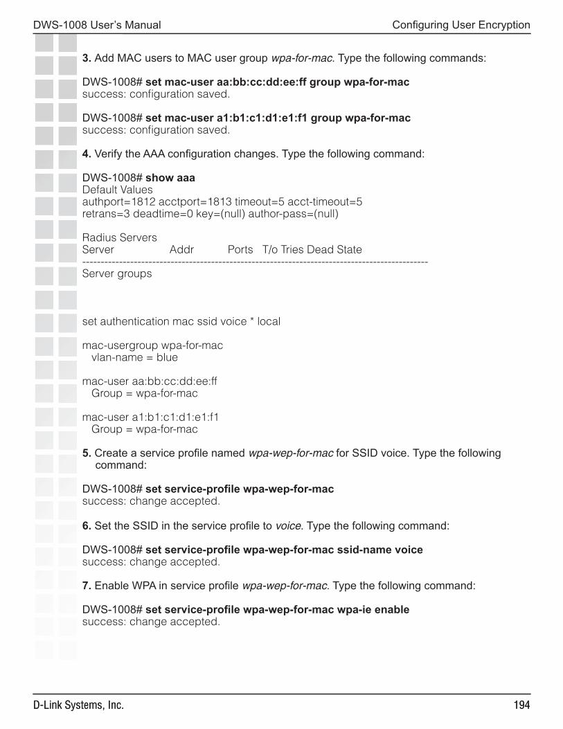
���
DWS-1008 User’s Manual
D-Link Systems, Inc.
Configuring User Encryption
���D-Link Systems, Inc.
3. Add MAC users to MAC user group wpa-for-mac. Type the following commands:
DWS-1008# set mac-user aa:bb:cc:dd:ee:ff group wpa-for-macsuccess: configuration saved.
DWS-1008# set mac-user a1:b1:c1:d1:e1:f1 group wpa-for-macsuccess: configuration saved.
4. Verify the AAA configuration changes. Type the following command:
DWS-1008# show aaaDefault Valuesauthport=1812 acctport=1813 timeout=5 acct-timeout=5retrans=3 deadtime=0 key=(null) author-pass=(null)
Radius ServersServer Addr Ports T/o Tries Dead State----------------------------------------------------------------------------------------------Server groups
set authentication mac ssid voice * local
mac-usergroup wpa-for-mac vlan-name = blue
mac-user aa:bb:cc:dd:ee:ff Group = wpa-for-mac
mac-user a1:b1:c1:d1:e1:f1 Group = wpa-for-mac
5. Create a service profile named wpa-wep-for-mac for SSID voice. Type the following command:
DWS-1008# set service-profile wpa-wep-for-macsuccess: change accepted.
6. Set the SSID in the service profile to voice. Type the following command:
DWS-1008# set service-profile wpa-wep-for-mac ssid-name voicesuccess: change accepted.
7. Enable WPA in service profile wpa-wep-for-mac. Type the following command:
DWS-1008# set service-profile wpa-wep-for-mac wpa-ie enablesuccess: change accepted.
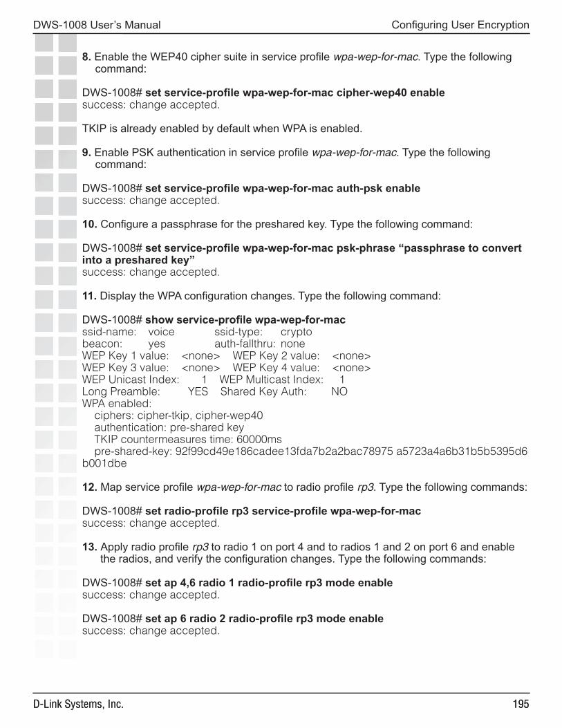
���
DWS-1008 User’s Manual
D-Link Systems, Inc.
Configuring User Encryption
���D-Link Systems, Inc.
8. Enable the WEP40 cipher suite in service profile wpa-wep-for-mac. Type the following command:
DWS-1008# set service-profile wpa-wep-for-mac cipher-wep40 enablesuccess: change accepted.
TKIP is already enabled by default when WPA is enabled.
9. Enable PSK authentication in service profile wpa-wep-for-mac. Type the following command:
DWS-1008# set service-profile wpa-wep-for-mac auth-psk enablesuccess: change accepted.
10. Configure a passphrase for the preshared key. Type the following command:
DWS-1008# set service-profile wpa-wep-for-mac psk-phrase “passphrase to convert into a preshared key”success: change accepted.
11. Display the WPA configuration changes. Type the following command:
DWS-1008# show service-profile wpa-wep-for-macssid-name: voice ssid-type: cryptobeacon: yes auth-fallthru: noneWEP Key 1 value: <none> WEP Key 2 value: <none>WEP Key 3 value: <none> WEP Key 4 value: <none>WEP Unicast Index: 1 WEP Multicast Index: 1Long Preamble: YES Shared Key Auth: NOWPA enabled: ciphers: cipher-tkip, cipher-wep40 authentication: pre-shared key TKIP countermeasures time: 60000ms pre-shared-key: 92f99cd49e186cadee13fda7b2a2bac78975 a5723a4a6b31b5b5395d6b001dbe
12. Map service profile wpa-wep-for-mac to radio profile rp3. Type the following commands: DWS-1008# set radio-profile rp3 service-profile wpa-wep-for-macsuccess: change accepted.
13. Apply radio profile rp3 to radio 1 on port 4 and to radios 1 and 2 on port 6 and enable the radios, and verify the configuration changes. Type the following commands:
DWS-1008# set ap 4,6 radio 1 radio-profile rp3 mode enablesuccess: change accepted.
DWS-1008# set ap 6 radio 2 radio-profile rp3 mode enablesuccess: change accepted.
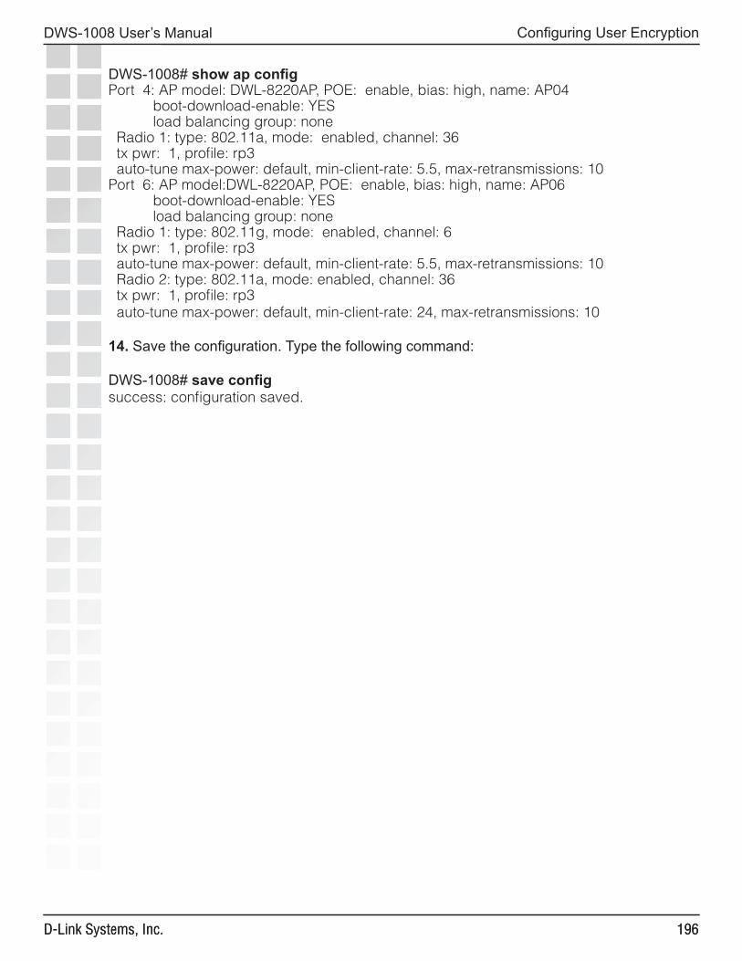
���
DWS-1008 User’s Manual
D-Link Systems, Inc.
Configuring User Encryption
���D-Link Systems, Inc.
DWS-1008# show ap configPort 4: AP model: DWL-8220AP, POE: enable, bias: high, name: AP04 boot-download-enable: YES load balancing group: none Radio 1: type: 802.11a, mode: enabled, channel: 36 tx pwr: 1, profile: rp3 auto-tune max-power: default, min-client-rate: 5.5, max-retransmissions: 10Port 6: AP model:DWL-8220AP, POE: enable, bias: high, name: AP06 boot-download-enable: YES load balancing group: none Radio 1: type: 802.11g, mode: enabled, channel: 6 tx pwr: 1, profile: rp3 auto-tune max-power: default, min-client-rate: 5.5, max-retransmissions: 10 Radio 2: type: 802.11a, mode: enabled, channel: 36 tx pwr: 1, profile: rp3 auto-tune max-power: default, min-client-rate: 24, max-retransmissions: 10
14. Save the configuration. Type the following command:
DWS-1008# save configsuccess: configuration saved.
���
DWS-1008 User’s Manual
D-Link Systems, Inc.
Configuring RF Auto-Tuning
Configuring RF Auto-TuningRF AutoTuning Overview
The RF AutoTuning feature dynamically assigns channel and power settings to AP radios, and adjusts those settings when needed. RF AutoTuning can perform the following tasks:
• Assign initial channel and power settings when an AP radio is started.
• Periodically assess the RF environment and change the channel or power setting if needed.
• Change the transmit data rate or power to maintain at least the minimum data rate with all associated clients.
By default, RF AutoTuning is enabled for channel configuration and disabled for power configuration.
Initial Channel and Power Assignment
The following process is used to assign the channel and power to an AP radio when it is first enabled:
• If RF AutoTuning is disabled for both channel and power assignment, the radio uses the channel and power settings in the radio profile that manages the radio. After this, the channel and power do not change unless you change the settings in the radio profile, or enable RF AutoTuning.
• If RF AutoTuning is enabled for channel and power assignment, the radio performs an RF scan and reports the results to the switch that is managing the AP the radio is on. The scan results include third-party access points. Based on the scan results, MSS sets the channel and power on the radio. MSS always selects channel and power settings that are valid for the country of operation.
• Initial channel assignment - MSS determines a radio’s initial channel based on RSSI values, interference levels on each valid channel, and other parameters. MSS periodically reevaluates the channel and changes it if needed.
• Initial power assignment - The DWL-8220AP sets a radio’s initial power level to the maximum value allowed for the country code (regulatory domain). In a deployment with few APs, the radio remains at maximum power. Otherwise, the radio reduces power until the power is just enough to reach the AP’s third-closest neighbor (for 802.11b/g) or eighth-closest neighbor (for 802.11a).
The radio can temporarily increase its power level based on client needs but returns to its default power level when clients no longer need the higher power level.
MSS periodically reevaluates the default power level and changes it if needed.
���
DWS-1008 User’s Manual
D-Link Systems, Inc.
Configuring RF Auto-Tuning
Channel and Power Tuning
RF AutoTuning can change the channel or power of a radio, to compensate for RF changes such as interference, or to maintain at least the minimum data transmit rate for associated clients. A radio continues to scan on its active data channel and on other channels and reports the results to its switch.
Periodically, the switch examines these results to determine whether the channel or the power needs to be changed.
Power Tuning
By default, the switch evaluates the scan results for possible power changes every 300 seconds (5 minutes), and raises or lowers the default power level if needed.
A radio can temporarily increase its power level from the default at any time to correct either of the following client-related symptoms:
• Increase in the number of duplicate packets received from a client. This symptom indicates that the AP radio’s acknowledgements (ACKs) are not reaching the client.
• Increase in the number of retransmissions of unicast packets from the radio to a client.
The radio uses two methods to treat these symptoms. First, if the data rate at which the radio is sending packets to the client is above the minimum data rate allowed, the radio lowers the unicast data rate with the client down to the next valid rate.
If the retransmissions still exceed the threshold, the radio continues to lower the data rate, one setting at a time, until either the retransmissions fall under the threshold or the minimum allowed data rate is reached.
If the retransmissions still exceed the threshold after the minimum allowed data rate is reached, the radio increases power by 1 dBm. The radio continues increasing the power in 1 dBm increments until the retransmissions fall to or below the threshold.
After the retransmissions fall to or below the threshold, the radio reduces power by 1 dBm. As long as retransmissions remain within the allowed threshold, the radio continues reducing power in 1 dBm increments until it returns to its default power level.
Channel Tuning
By default, the switch evaluates the scan results for possible channel changes every 3600 seconds (1 hour). MSS uses the following parameters to determine whether to change the channel on a radio:
• Received signal strength indication (RSSI)
• Amount of noise on the channel
• Packet retransmission count, which is the rate at which the radio receives retransmitted packets.
���
DWS-1008 User’s Manual
D-Link Systems, Inc.
Configuring RF Auto-Tuning
• Utilization, calculated based on the number of multicast packets per second that a radio can send on a channel while continuously sending fixed-size frames over a period of time.
• Phy error count, which is the number of frames received by the AP radio that have physical layer errors. A high number of Phy errors can indicate the presence of a non-802.11 device using the same RF spectrum.
• Received CRC error count. A high number of CRC errors can indicate a hidden node or co-channel interference.
The thresholds for these parameters are not configurable. RF AutoTuning also can change a radio’s channel when the channel tuning interval expires, if a channel that has less disturbance is detected. Disturbance is based on the number of neighbors the radio has and each neighbor’s RSSI.
A radio also can change its channel before the channel tuning interval expires to respond to RF anomalies. An RF anomaly is a sudden major change in the RF environment, such as sudden major interference on the channel.
By default, a radio cannot change its channel more often than every 900 seconds, regardless of the RF environment. This channel holddown avoids unnecessary changes due to very transient RF changes, such as activation of a microwave oven.
Tuning the Transmit Data Rate
A radio sends beacons, probe requests, and probe responses at the minimum transmit data rate allowed for clients. This gives them the maximum distance. All other packets are transmitted at a rate determined by their destination. All packets are transmitted at the same power level.
By default, the following minimum data rates are allowed:
• 5.5 Mbps for 802.11b/g clients• 24 Mbps for 802.11a clients
RF AutoTuning Parameters
The table below lists the RF AutoTuning parameters and their default settings.
Defaults for RF AutoTuning Parameters
Parameter Default Value
Radio Behavior When Parameter Set To Default Value
Radio profile parameterschannel-config enable When the radio is first enabled,
RF AutoTuning sets the channel based on the channels in use on neighboring access points.
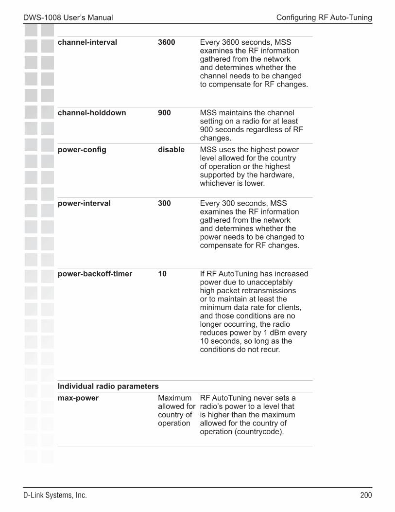
�00
DWS-1008 User’s Manual
D-Link Systems, Inc.
Configuring RF Auto-Tuning
channel-interval 3600 Every 3600 seconds, MSS examines the RF information gathered from the network and determines whether the channel needs to be changed to compensate for RF changes.
channel-holddown 900 MSS maintains the channel setting on a radio for at least 900 seconds regardless of RF changes.
power-config disable MSS uses the highest power level allowed for the country of operation or the highest supported by the hardware, whichever is lower.
power-interval 300 Every 300 seconds, MSS examines the RF information gathered from the network and determines whether the power needs to be changed to compensate for RF changes.
power-backoff-timer 10 If RF AutoTuning has increased power due to unacceptably high packet retransmissions or to maintain at least the minimum data rate for clients, and those conditions are no longer occurring, the radio reduces power by 1 dBm every 10 seconds, so long as the conditions do not recur.
Individual radio parametersmax-power Maximum
allowed for country of operation
RF AutoTuning never sets a radio’s power to a level that is higher than the maximum allowed for the country of operation (countrycode).
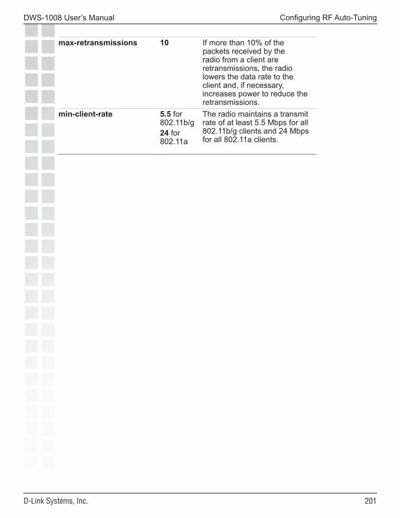
�0�
DWS-1008 User’s Manual
D-Link Systems, Inc.
Configuring RF Auto-Tuning
max-retransmissions 10 If more than 10% of the packets received by the radio from a client are retransmissions, the radio lowers the data rate to the client and, if necessary, increases power to reduce the retransmissions.
min-client-rate 5.5 for 802.11b/g24 for 802.11a
The radio maintains a transmit rate of at least 5.5 Mbps for all 802.11b/g clients and 24 Mbps for all 802.11a clients.
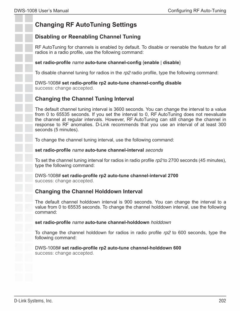
�0�
DWS-1008 User’s Manual
D-Link Systems, Inc.
Configuring RF Auto-Tuning
Changing RF AutoTuning Settings Disabling or Reenabling Channel Tuning
RF AutoTuning for channels is enabled by default. To disable or reenable the feature for all radios in a radio profile, use the following command:
set radio-profile name auto-tune channel-config {enable | disable}
To disable channel tuning for radios in the rp2 radio profile, type the following command:
DWS-1008# set radio-profile rp2 auto-tune channel-config disablesuccess: change accepted.
Changing the Channel Tuning Interval
The default channel tuning interval is 3600 seconds. You can change the interval to a value from 0 to 65535 seconds. If you set the interval to 0, RF AutoTuning does not reevaluate the channel at regular intervals. However, RF AutoTuning can still change the channel in response to RF anomalies. D-Link recommends that you use an interval of at least 300 seconds (5 minutes).
To change the channel tuning interval, use the following command:
set radio-profile name auto-tune channel-interval seconds
To set the channel tuning interval for radios in radio profile rp2 to 2700 seconds (45 minutes), type the following command:
DWS-1008# set radio-profile rp2 auto-tune channel-interval 2700success: change accepted.
Changing the Channel Holddown Interval
The default channel holddown interval is 900 seconds. You can change the interval to a value from 0 to 65535 seconds. To change the channel holddown interval, use the following command:
set radio-profile name auto-tune channel-holddown holddown
To change the channel holddown for radios in radio profile rp2 to 600 seconds, type the following command:
DWS-1008# set radio-profile rp2 auto-tune channel-holddown 600success: change accepted.
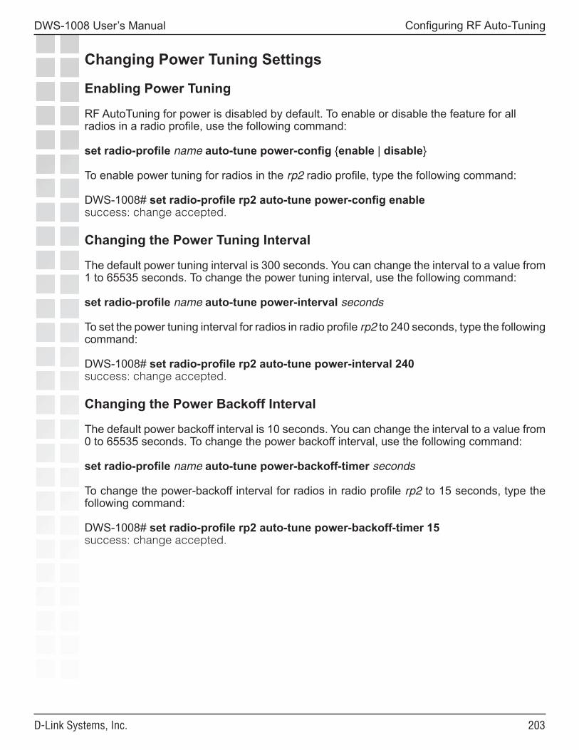
�0�
DWS-1008 User’s Manual
D-Link Systems, Inc.
Configuring RF Auto-Tuning
Changing Power Tuning Settings
Enabling Power Tuning
RF AutoTuning for power is disabled by default. To enable or disable the feature for all radios in a radio profile, use the following command:
set radio-profile name auto-tune power-config {enable | disable}
To enable power tuning for radios in the rp2 radio profile, type the following command:
DWS-1008# set radio-profile rp2 auto-tune power-config enablesuccess: change accepted.
Changing the Power Tuning Interval
The default power tuning interval is 300 seconds. You can change the interval to a value from 1 to 65535 seconds. To change the power tuning interval, use the following command:
set radio-profile name auto-tune power-interval seconds
To set the power tuning interval for radios in radio profile rp2 to 240 seconds, type the following command:
DWS-1008# set radio-profile rp2 auto-tune power-interval 240success: change accepted.
Changing the Power Backoff Interval
The default power backoff interval is 10 seconds. You can change the interval to a value from 0 to 65535 seconds. To change the power backoff interval, use the following command:
set radio-profile name auto-tune power-backoff-timer seconds
To change the power-backoff interval for radios in radio profile rp2 to 15 seconds, type the following command:
DWS-1008# set radio-profile rp2 auto-tune power-backoff-timer 15success: change accepted.
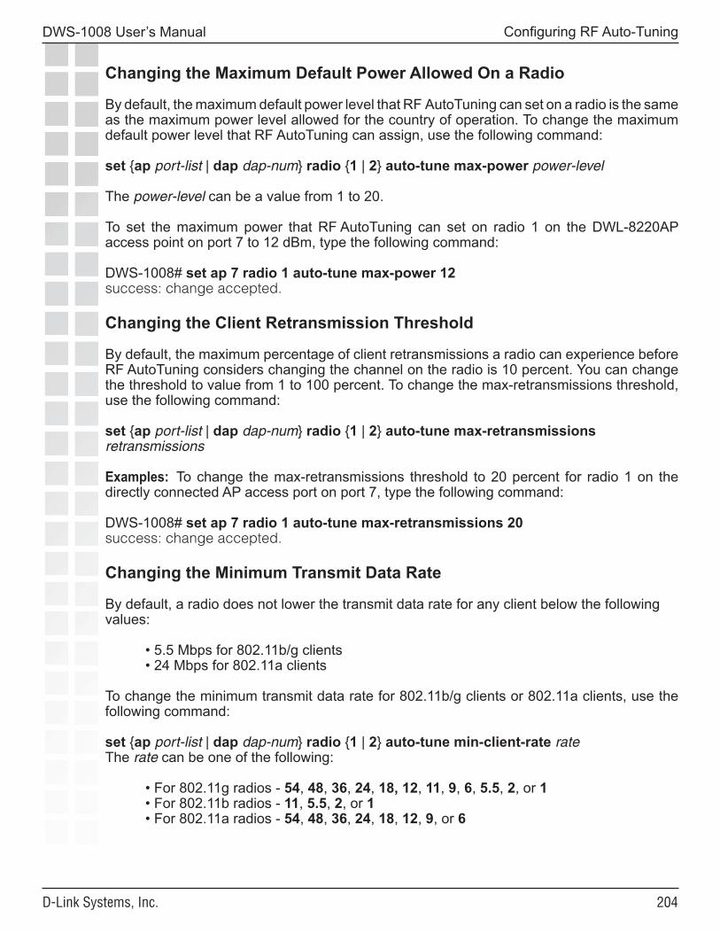
�0�
DWS-1008 User’s Manual
D-Link Systems, Inc.
Configuring RF Auto-Tuning
Changing the Maximum Default Power Allowed On a Radio
By default, the maximum default power level that RF AutoTuning can set on a radio is the same as the maximum power level allowed for the country of operation. To change the maximum default power level that RF AutoTuning can assign, use the following command:
set {ap port-list | dap dap-num} radio {1 | 2} auto-tune max-power power-level
The power-level can be a value from 1 to 20.
To set the maximum power that RF AutoTuning can set on radio 1 on the DWL-8220AP access point on port 7 to 12 dBm, type the following command:
DWS-1008# set ap 7 radio 1 auto-tune max-power 12success: change accepted.
Changing the Client Retransmission Threshold
By default, the maximum percentage of client retransmissions a radio can experience before RF AutoTuning considers changing the channel on the radio is 10 percent. You can change the threshold to value from 1 to 100 percent. To change the max-retransmissions threshold, use the following command:
set {ap port-list | dap dap-num} radio {1 | 2} auto-tune max-retransmissions retransmissions
Examples: To change the max-retransmissions threshold to 20 percent for radio 1 on the directly connected AP access port on port 7, type the following command:
DWS-1008# set ap 7 radio 1 auto-tune max-retransmissions 20success: change accepted.
Changing the Minimum Transmit Data Rate
By default, a radio does not lower the transmit data rate for any client below the following values:
• 5.5 Mbps for 802.11b/g clients• 24 Mbps for 802.11a clients
To change the minimum transmit data rate for 802.11b/g clients or 802.11a clients, use the following command:
set {ap port-list | dap dap-num} radio {1 | 2} auto-tune min-client-rate rateThe rate can be one of the following:
• For 802.11g radios - 54, 48, 36, 24, 18, 12, 11, 9, 6, 5.5, 2, or 1• For 802.11b radios - 11, 5.5, 2, or 1• For 802.11a radios - 54, 48, 36, 24, 18, 12, 9, or 6
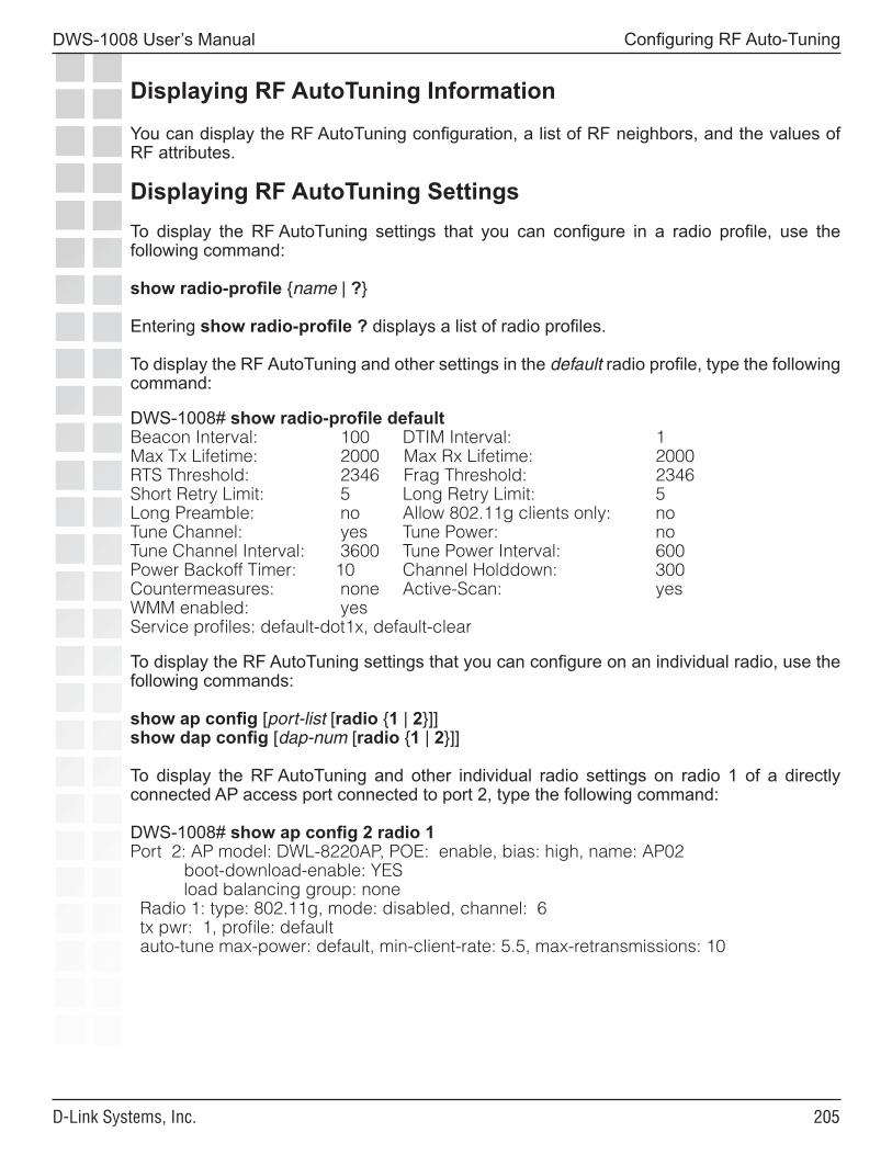
�0�
DWS-1008 User’s Manual
D-Link Systems, Inc.
Configuring RF Auto-Tuning
Displaying RF AutoTuning Information
You can display the RF AutoTuning configuration, a list of RF neighbors, and the values of RF attributes.
Displaying RF AutoTuning SettingsTo display the RF AutoTuning settings that you can configure in a radio profile, use the following command:
show radio-profile {name | ?}
Entering show radio-profile ? displays a list of radio profiles.
To display the RF AutoTuning and other settings in the default radio profile, type the following command:
DWS-1008# show radio-profile defaultBeacon Interval: 100 DTIM Interval: 1Max Tx Lifetime: 2000 Max Rx Lifetime: 2000RTS Threshold: 2346 Frag Threshold: 2346Short Retry Limit: 5 Long Retry Limit: 5Long Preamble: no Allow 802.11g clients only: noTune Channel: yes Tune Power: noTune Channel Interval: 3600 Tune Power Interval: 600Power Backoff Timer: 10 Channel Holddown: 300Countermeasures: none Active-Scan: yesWMM enabled: yesService profiles: default-dot1x, default-clear
To display the RF AutoTuning settings that you can configure on an individual radio, use the following commands:
show ap config [port-list [radio {1 | 2}]]show dap config [dap-num [radio {1 | 2}]]
To display the RF AutoTuning and other individual radio settings on radio 1 of a directly connected AP access port connected to port 2, type the following command:
DWS-1008# show ap config 2 radio 1Port 2: AP model: DWL-8220AP, POE: enable, bias: high, name: AP02 boot-download-enable: YES load balancing group: none Radio 1: type: 802.11g, mode: disabled, channel: 6 tx pwr: 1, profile: default auto-tune max-power: default, min-client-rate: 5.5, max-retransmissions: 10
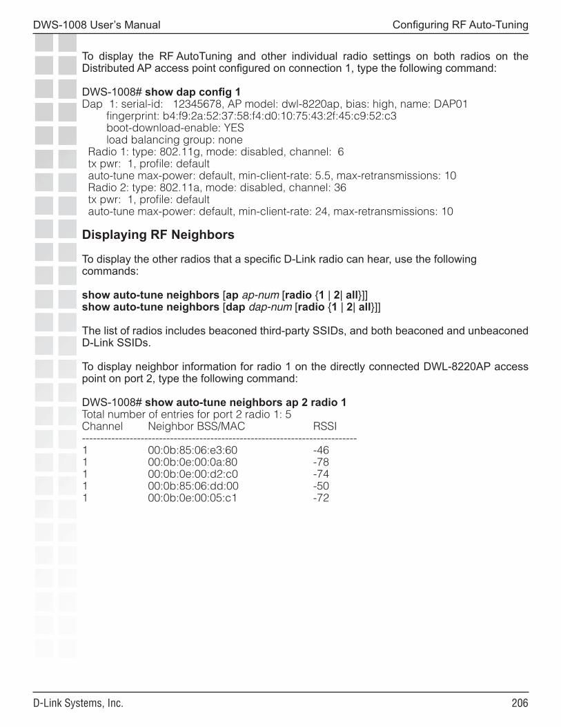
�0�
DWS-1008 User’s Manual
D-Link Systems, Inc.
Configuring RF Auto-Tuning
To display the RF AutoTuning and other individual radio settings on both radios on the Distributed AP access point configured on connection 1, type the following command:
DWS-1008# show dap config 1Dap 1: serial-id: 12345678, AP model: dwl-8220ap, bias: high, name: DAP01 fingerprint: b4:f9:2a:52:37:58:f4:d0:10:75:43:2f:45:c9:52:c3 boot-download-enable: YES load balancing group: none Radio 1: type: 802.11g, mode: disabled, channel: 6 tx pwr: 1, profile: default auto-tune max-power: default, min-client-rate: 5.5, max-retransmissions: 10 Radio 2: type: 802.11a, mode: disabled, channel: 36 tx pwr: 1, profile: default auto-tune max-power: default, min-client-rate: 24, max-retransmissions: 10
Displaying RF Neighbors
To display the other radios that a specific D-Link radio can hear, use the following commands:
show auto-tune neighbors [ap ap-num [radio {1 | 2| all}]]show auto-tune neighbors [dap dap-num [radio {1 | 2| all}]]
The list of radios includes beaconed third-party SSIDs, and both beaconed and unbeaconed D-Link SSIDs.
To display neighbor information for radio 1 on the directly connected DWL-8220AP access point on port 2, type the following command:
DWS-1008# show auto-tune neighbors ap 2 radio 1Total number of entries for port 2 radio 1: 5Channel Neighbor BSS/MAC RSSI---------------------------------------------------------------------------1 00:0b:85:06:e3:60 -461 00:0b:0e:00:0a:80 -781 00:0b:0e:00:d2:c0 -741 00:0b:85:06:dd:00 -501 00:0b:0e:00:05:c1 -72
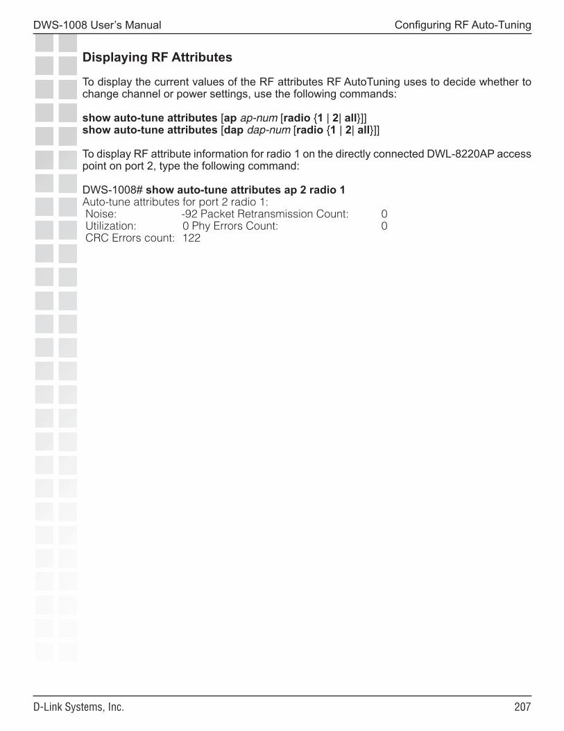
�0�
DWS-1008 User’s Manual
D-Link Systems, Inc.
Configuring RF Auto-Tuning
Displaying RF Attributes
To display the current values of the RF attributes RF AutoTuning uses to decide whether to change channel or power settings, use the following commands:
show auto-tune attributes [ap ap-num [radio {1 | 2| all}]]show auto-tune attributes [dap dap-num [radio {1 | 2| all}]]
To display RF attribute information for radio 1 on the directly connected DWL-8220AP access point on port 2, type the following command:
DWS-1008# show auto-tune attributes ap 2 radio 1Auto-tune attributes for port 2 radio 1: Noise: -92 Packet Retransmission Count: 0 Utilization: 0 Phy Errors Count: 0 CRC Errors count: 122

�0�
DWS-1008 User’s Manual
D-Link Systems, Inc.
Wi-Fi Multimedia
Wi-Fi MultimediaMSS supports Wi-Fi Multimedia (WMM). WMM provides wireless Quality of Service for time-sensitive applications such as voice and video. WMM is a pre-standard version of IEEE 802.11e, provided by the Wi-Fi Alliance to enable vendors to provide interoperable multimedia support before ratification of the standard.
WMM maps priority information between wired and wireless packets, so that high priority traffic receives end-to-end high priority treatment through the network. WMM is enabled by default and does not require any configuration. You can disable the feature on individual radio profiles.
Note: MSS also can support non-WMM VoIP devices. However, to provide priority service to non-WMM VoIP traffic, you must configure an ACL to set the CoS (Case of Service) for the traffic. The AP maps this CoS value to a forwarding queue.
How WMM Works in MSSDWS-1008 switches support WMM by tagging QoS information in packets. MSS classifies QoS information in a packet received by the switch. MSS then tags the packet’s QoS information before forwarding the packet. Depending on the destination, MSS can set QoS information by setting a packet’s 802.1p value or by setting the IP ToS value in the IP tunnel header, if the traffic is tunneled. MSS does not change the IP ToS value in the data packets themselves.
QoS on the DWS-1008 Switch
The switch obtains an inbound packet’s QoS value from the packet’s Layer 2 802.1p or Layer 3 IP ToS value. Depending on the destination, the switch maps the QoS information to other parts of the packet before forwarding it. If a packet has both 802.1p and IP ToS information, the switch sets QoS for the packet based on the IP ToS value.
However, if an ACL is mapped to the outbound traffic direction on the AP port, Distributed AP, or user VLAN, the switch sets QoS based on the CoS value in the ACL, regardless of the 802.1p and IP ToS values in the packet.
• If the switch is forwarding a packet to an AP, MSS encapsulates the packet in an IP tunnel, and marks the IP ToS value in the tunnel header based on the incoming QoS value. This occurs for directly connected APs and for Distributed APs. The switch never changes the data packet’s IP ToS value.
• If the DWS-1008 is forwarding a packet through a tunnel to another switch, MSS uses the same process used for traffic to an AP. Generally, a switch uses a tunnel to send user data to another DWS-1008 switch when the user’s VLAN is configured on the other switch but not on the local switch.
• If the switch is forwarding a packet on a wired interface that has an 802.1Q VLAN tag, the switch sets the packet’s 802.1p value based on the incoming QoS value.
• If the switch is forwarding a packet to a non-tagged wired interface, and the traffic is not tunneled, the switch does not set the data packet’s 802.1p value.
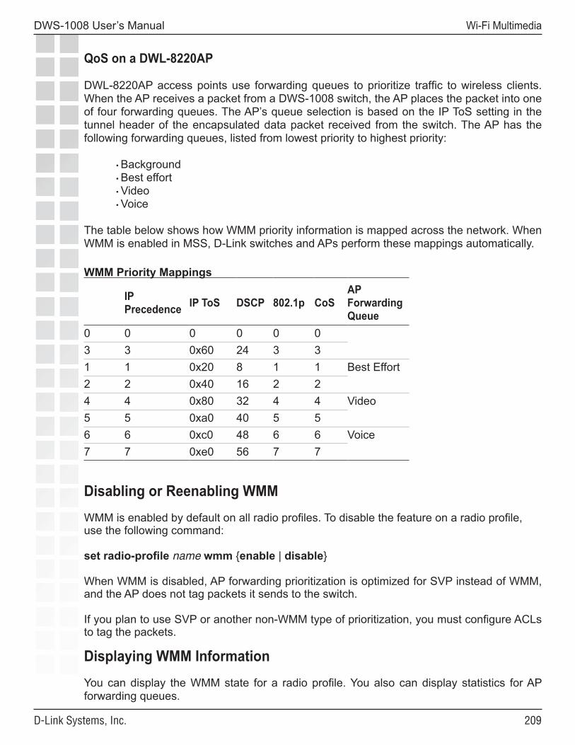
�0�
DWS-1008 User’s Manual
D-Link Systems, Inc.
Wi-Fi Multimedia
QoS on a DWL-8220AP
DWL-8220AP access points use forwarding queues to prioritize traffic to wireless clients. When the AP receives a packet from a DWS-1008 switch, the AP places the packet into one of four forwarding queues. The AP’s queue selection is based on the IP ToS setting in the tunnel header of the encapsulated data packet received from the switch. The AP has the following forwarding queues, listed from lowest priority to highest priority:
• Background• Best effort• Video• Voice
The table below shows how WMM priority information is mapped across the network. When WMM is enabled in MSS, D-Link switches and APs perform these mappings automatically.
WMM Priority Mappings
IP Precedence IP ToS DSCP 802.1p CoS
AP Forwarding Queue
0 0 0 0 0 03 3 0x60 24 3 31 1 0x20 8 1 1 Best Effort2 2 0x40 16 2 24 4 0x80 32 4 4 Video5 5 0xa0 40 5 56 6 0xc0 48 6 6 Voice7 7 0xe0 56 7 7
Disabling or Reenabling WMMWMM is enabled by default on all radio profiles. To disable the feature on a radio profile, use the following command:
set radio-profile name wmm {enable | disable}
When WMM is disabled, AP forwarding prioritization is optimized for SVP instead of WMM, and the AP does not tag packets it sends to the switch.
If you plan to use SVP or another non-WMM type of prioritization, you must configure ACLs to tag the packets.
Displaying WMM InformationYou can display the WMM state for a radio profile. You also can display statistics for AP forwarding queues.
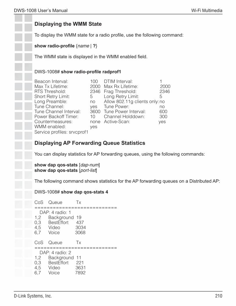
��0
DWS-1008 User’s Manual
D-Link Systems, Inc.
Wi-Fi Multimedia
Displaying the WMM State
To display the WMM state for a radio profile, use the following command:
show radio-profile {name | ?}
The WMM state is displayed in the WMM enabled field.
DWS-1008# show radio-profile radprof1
Beacon Interval: 100 DTIM Interval: 1Max Tx Lifetime: 2000 Max Rx Lifetime: 2000RTS Threshold: 2346 Frag Threshold: 2346Short Retry Limit: 5 Long Retry Limit: 5Long Preamble: no Allow 802.11g clients only: noTune Channel: yes Tune Power: noTune Channel Interval: 3600 Tune Power Interval: 600Power Backoff Timer: 10 Channel Holddown: 300Countermeasures: none Active-Scan: yesWMM enabled: yesService profiles: srvcprof1
Displaying AP Forwarding Queue Statistics
You can display statistics for AP forwarding queues, using the following commands:
show dap qos-stats [dap-num]show dap qos-stats [port-list]
The following command shows statistics for the AP forwarding queues on a Distributed AP:
DWS-1008# show dap qos-stats 4 CoS Queue Tx =========================== DAP: 4 radio: 11,2 Background 190,3 BestEffort 4374,5 Video 30346,7 Voice 3068
CoS Queue Tx =========================== DAP: 4 radio: 21,2 Background 110,3 BestEffort 2214,5 Video 36316,7 Voice 7892
���
DWS-1008 User’s Manual
D-Link Systems, Inc.
Configuring and Managing STP
Configuring and Managing Spanning Tree Protocol
The purpose of the Spanning Tree Protocol (STP) is to maintain a loop-free network. A loop-free path is accomplished when a device recognizes a loop in the topology and blocks one or more redundant paths.
Mobility System Software (MSS) supports 802.1D and Per-VLAN Spanning Tree protocol (PVST+).
• MSS uses 802.1D bridge protocol data units (BPDUs) on VLAN ports that are untagged. However, each VLAN still runs its own instance of STP, even if two or more VLANs contain untagged ports. To run a single instance of STP in 802.1D mode on the entire switch, configure all network ports as untagged members of the same VLAN. MSS does not support running 802.1D on multiple tagged VLANs.
• MSS uses PVST+ BPDUs on VLAN ports that are tagged. PVST+ BPDUs include tag information in the 802.1Q field of the BPDUs. MSS runs a separate instance of PVST+ on each tagged VLAN.
Enabling the Spanning Tree Protocol
STP is disabled by default. You can enable STP globally or on individual VLANs. To enable STP, use the following command:
set spantree {enable | disable} [{all | vlan vlan-id | port port-list vlan-id}]
To enable STP on all VLANs configured on a DWS-1008 switch, type the following command:
DWS-1008# set spantree enablesuccess: change accepted.
To verify the STP state and display the STP parameter settings, enter the show spantree command.
Changing Standard Spanning Tree Parameters
You can change the following standard STP parameters:
• Bridge priority• Port cost• Port priority
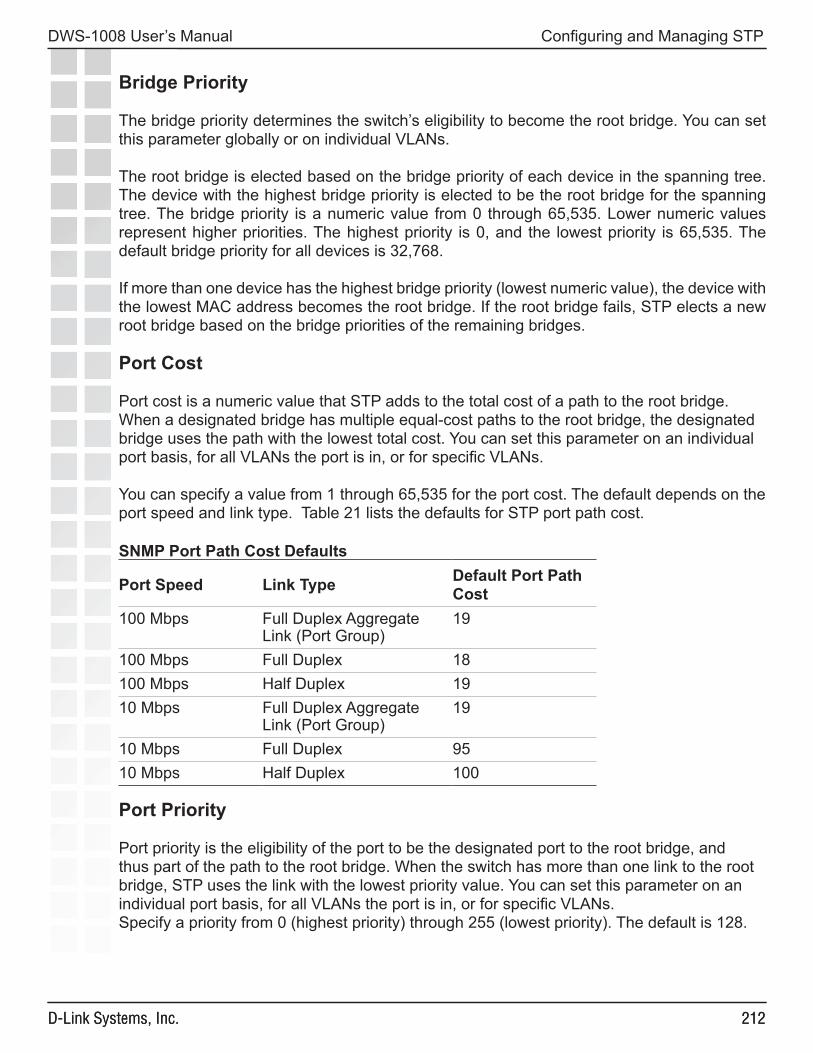
���
DWS-1008 User’s Manual
D-Link Systems, Inc.
Configuring and Managing STP
���D-Link Systems, Inc.
Bridge Priority
The bridge priority determines the switch’s eligibility to become the root bridge. You can set this parameter globally or on individual VLANs.
The root bridge is elected based on the bridge priority of each device in the spanning tree. The device with the highest bridge priority is elected to be the root bridge for the spanning tree. The bridge priority is a numeric value from 0 through 65,535. Lower numeric values represent higher priorities. The highest priority is 0, and the lowest priority is 65,535. The default bridge priority for all devices is 32,768.
If more than one device has the highest bridge priority (lowest numeric value), the device with the lowest MAC address becomes the root bridge. If the root bridge fails, STP elects a new root bridge based on the bridge priorities of the remaining bridges.
Port Cost
Port cost is a numeric value that STP adds to the total cost of a path to the root bridge. When a designated bridge has multiple equal-cost paths to the root bridge, the designated bridge uses the path with the lowest total cost. You can set this parameter on an individual port basis, for all VLANs the port is in, or for specific VLANs.
You can specify a value from 1 through 65,535 for the port cost. The default depends on the port speed and link type. Table 21 lists the defaults for STP port path cost.
SNMP Port Path Cost Defaults
Port Speed Link Type Default Port Path Cost
100 Mbps Full Duplex Aggregate Link (Port Group)
19
100 Mbps Full Duplex 18100 Mbps Half Duplex 1910 Mbps Full Duplex Aggregate
Link (Port Group)19
10 Mbps Full Duplex 9510 Mbps Half Duplex 100
Port Priority
Port priority is the eligibility of the port to be the designated port to the root bridge, and thus part of the path to the root bridge. When the switch has more than one link to the root bridge, STP uses the link with the lowest priority value. You can set this parameter on an individual port basis, for all VLANs the port is in, or for specific VLANs.Specify a priority from 0 (highest priority) through 255 (lowest priority). The default is 128.
���
DWS-1008 User’s Manual
D-Link Systems, Inc.
Configuring and Managing STP
���D-Link Systems, Inc.
Changing the Bridge Priority
To change the bridge priority, use the following command:
set spantree priority value {all | vlan vlan-id}
Specify a bridge priority from 0 through 65,535. The default is 32,768. The all option applies the change globally to all VLANs. Alternatively, specify an individual VLAN.
To change the bridge priority of VLAN pink to 70, type the following command:
DWS-1008# set spantree priority 70 vlan pinksuccess: change accepted.
Changing STP Port Parameters
You can change the STP cost and priority of an individual port, on a global basis or an individual VLAN basis.
Changing the STP Port Cost
To change the cost of a port, use one of the following commands.
set spantree portcost port-list cost costset spantree portvlancost port-list cost cost {all | vlan vlan-id}
The set spantree portcost command changes the cost for ports in the default VLAN (VLAN 1) only. The set spantree portvlancost command changes the cost for ports in a specific other VLAN or in all VLANs. Specify a value from 1 through 65,535 for the cost. The default depends on the port speed and link type.
The all option applies the change to all VLANs. Alternatively, specify an individual VLAN. To change the cost on ports 3 and 4 in the default VLAN to 20, type the following command: DWS-1008# set spantree portcost 3,4 cost 20success: change accepted.To change the cost for the same ports in VLAN mauve, type the following command:
DWS-1008# set spantree portvlancost 3,4 cost 20 vlan mauvesuccess: change accepted.
Resetting the STP Port Cost to the Default Value
To reset the STP port cost to the default value, use one of the following commands:
clear spantree portcost port-listclear spantree portvlancost port-list {all | vlan vlan-id}
���
DWS-1008 User’s Manual
D-Link Systems, Inc.
Configuring and Managing STP
���D-Link Systems, Inc.
The command applies only to the ports you specify. The port cost on other ports remains unchanged.
To reset the cost of ports 3 and 4 in the default VLAN to the default value, type the following command:
DWS-1008# clear spantree portcost 3-4success: change accepted.
To reset the cost of ports 3 and 4 for VLAN beige, type the following command:
DWS-1008# clear spantree portvlancost 3-4 vlan beigesuccess: change accepted.
Changing the STP Port Priority
To change the priority of a port, use one of the following commands:set spantree portpri port-list priority valueset spantree portvlanpri port-list priority value {all | vlan vlan-id}
The set spantree portpri command changes the priority for ports in the default VLAN (VLAN 1) only. The set spantree portvlanpri command changes the priority for ports in a specific other VLAN or in all VLANs.
Specify a priority from 0 (highest priority) through 255 (lowest priority). The default is 128.The all option applies the change to all VLANs. Alternatively, specify an individual VLAN.
To set the priority of ports 3 and 4 in the default VLAN to 48, type the following command:
DWS-1008# set spantree portpri 3-4 priority 48success: change accepted.To set the priority of ports 3 and 4 to 48 in VLAN mauve, type the following command:
DWS-1008# set spantree portvlanpri 3-4 priority 48 vlan mauvesuccess: change accepted.
Resetting the STP Port Priority to the Default Value
To reset the STP port priority to the default value, use one of the following commands:
clear spantree portpri port-listclear spantree portvlanpri port-list {all | vlan vlan-id}
The command applies only to the ports you specify. The port cost on other ports remains unchanged.
���
DWS-1008 User’s Manual
D-Link Systems, Inc.
Configuring and Managing STP
���D-Link Systems, Inc.
Changing Spanning Tree Timers
You can change the following STP timers:
• Hello interval - The interval between configuration messages sent by a switch when the switch is acting as the root bridge. You can specify an interval from 1 through 10 seconds. The default is 2 seconds.
• Forwarding delay - The period of time a bridge other than the root bridge waits after receiving a topology change notification to begin forwarding data packets. You can specify a delay from 4 through 30 seconds. The default is 15 seconds. (The root bridge always forwards traffic.)
• Maximum age - The period of time that a switch acting as a designated bridge waits for a new hello packet from the root bridge before determining that the root bridge is no longer available and initiating a topology change. You can specify an age from 6 through 40 seconds. The default is 20 seconds.
Changing the STP Hello Interval
To change the hello interval, use the following command:
set spantree hello interval {all | vlan vlan-id}
Specify an interval from 1 through 10 seconds. The default is 2 seconds.
The all option applies the change to all VLANs. Alternatively, specify an individual VLAN. To change the hello interval for all VLANs to 4 seconds, type the following command:
DWS-1008# set spantree hello 4 allsuccess: change accepted.
Changing the STP Forwarding Delay
To change the forwarding delay, use the following command:
set spantree fwddelay delay {all | vlan vlan-id}
Specify a delay from 4 through 30 seconds. The default is 15 seconds.
The all option applies the change to all VLANs. Alternatively, specify an individual VLAN. To change the forwarding delay on VLAN pink to 20 seconds, type the following command:
DWS-1008# set spantree fwddelay 20 vlan pinksuccess: change accepted.
���
DWS-1008 User’s Manual
D-Link Systems, Inc.
Configuring and Managing STP
���D-Link Systems, Inc.
Changing the STP Maximum Age
To change the maximum age, use the following command:
set spantree maxage aging-time {all | vlan vlan-id}
Specify an age from 6 through 40 seconds. The default is 20 seconds.
The all option applies the change to all VLANs. Alternatively, specify an individual VLAN. To change the maximum acceptable age for root bridge hello packets on all VLANs to 15 seconds, type the following command:
DWS-1008# set spantree maxage 15 allsuccess: change accepted.
Configuring and Managing STP Fast Convergence Features
The standard STP timers delay traffic forwarding briefly after a topology change. The time a port takes to change from the listening state to the learning state or from the learning state to the forwarding state is called the forwarding delay. In some configurations, this delay is unnecessary. The switch provides the following fast convergence features to bypass the forwarding delay:
• Port fast• Backbone fast• Uplink fast
Port Fast Convergence
Port fast convergence bypasses both the listening and learning stages and immediately places a port in the forwarding state. You can use port fast convergence on ports that are directly connected to servers, hosts, or other MAC stations.
Note: Do not use port fast convergence on ports connected to other bridges.
Backbone Fast Convergence
Backbone fast convergence accelerates a port’s recovery following the failure of an indirect link. Normally, when a forwarding link fails, a bridge that is not directly connected to the link does not detect the link change until the maximum age timer expires. Backbone fast convergence enables the switch to listen for bridge protocol data units (BPDUs) sent by a designated bridge when the designated bridge’s link to the root bridge fails. The switch immediately verifies whether BPDU information stored on a port is still valid. If not, the bridge immediately starts the listening stage on the port.
Note: If you plan to use the backbone fast convergence feature, you must enable it on all the bridges in the spanning tree.
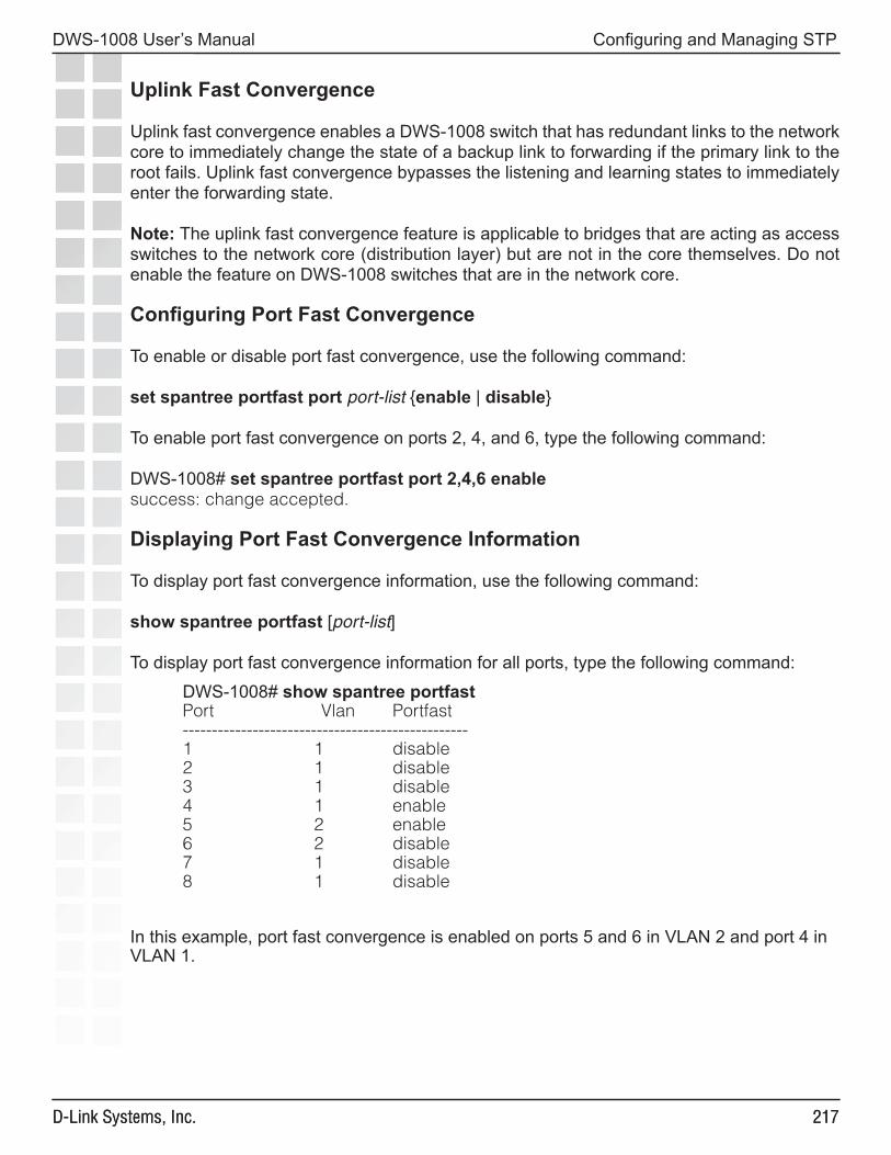
���
DWS-1008 User’s Manual
D-Link Systems, Inc.
Configuring and Managing STP
���D-Link Systems, Inc.
Uplink Fast Convergence
Uplink fast convergence enables a DWS-1008 switch that has redundant links to the network core to immediately change the state of a backup link to forwarding if the primary link to the root fails. Uplink fast convergence bypasses the listening and learning states to immediately enter the forwarding state.
Note: The uplink fast convergence feature is applicable to bridges that are acting as access switches to the network core (distribution layer) but are not in the core themselves. Do not enable the feature on DWS-1008 switches that are in the network core.
Configuring Port Fast Convergence
To enable or disable port fast convergence, use the following command:
set spantree portfast port port-list {enable | disable}
To enable port fast convergence on ports 2, 4, and 6, type the following command:
DWS-1008# set spantree portfast port 2,4,6 enablesuccess: change accepted.
Displaying Port Fast Convergence Information
To display port fast convergence information, use the following command:
show spantree portfast [port-list]
To display port fast convergence information for all ports, type the following command:
DWS-1008# show spantree portfastPort Vlan Portfast-------------------------------------------------1 1 disable2 1 disable3 1 disable4 1 enable5 2 enable6 2 disable7 1 disable8 1 disable
In this example, port fast convergence is enabled on ports 5 and 6 in VLAN 2 and port 4 in VLAN 1.
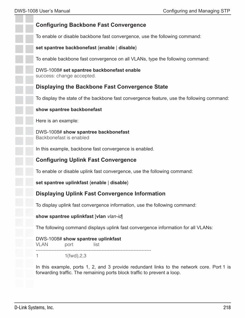
���
DWS-1008 User’s Manual
D-Link Systems, Inc.
Configuring and Managing STP
���D-Link Systems, Inc.
Configuring Backbone Fast Convergence
To enable or disable backbone fast convergence, use the following command:
set spantree backbonefast {enable | disable}
To enable backbone fast convergence on all VLANs, type the following command:
DWS-1008# set spantree backbonefast enablesuccess: change accepted.
Displaying the Backbone Fast Convergence State
To display the state of the backbone fast convergence feature, use the following command:
show spantree backbonefast
Here is an example:
DWS-1008# show spantree backbonefastBackbonefast is enabled
In this example, backbone fast convergence is enabled.
Configuring Uplink Fast Convergence
To enable or disable uplink fast convergence, use the following command:
set spantree uplinkfast {enable | disable}
Displaying Uplink Fast Convergence Information
To display uplink fast convergence information, use the following command:
show spantree uplinkfast [vlan vlan-id]
The following command displays uplink fast convergence information for all VLANs:
DWS-1008# show spantree uplinkfastVLAN port list------------------------------------------------------------------------1 1(fwd),2,3
In this example, ports 1, 2, and 3 provide redundant links to the network core. Port 1 is forwarding traffic. The remaining ports block traffic to prevent a loop.

���
DWS-1008 User’s Manual
D-Link Systems, Inc.
Configuring and Managing STP
���D-Link Systems, Inc.
Displaying Spanning Tree Information
You can use CLI commands to display the following STP information:
• Bridge STP settings and individual port information• Blocked ports• Statistics• Port fast, backbone fast, and uplink fast convergence information
Displaying STP Bridge and Port Information
To display STP bridge and port information, use the following command:
show spantree [port-list | vlan vlan-id] [active]
By default, STP information for all ports and all VLANs is displayed. To display STP information for specific ports or a specific VLAN only, enter a port list or a VLAN name or number. For each VLAN, only the ports contained in the VLAN are listed in the command output.
To list only the ports that are in the active (forwarding) state, enter the active option. To display STP information for VLAN mauve, type the following command:
DWS-1008# show spantree vlan mauveVLAN 3Spanning tree mode PVST+Spanning tree type IEEESpanning tree enabledDesignated Root 00-02-4a-70-49-f7Designated Root Priority 32768Designated Root Path Cost 19Designated Root Port 1Root Max Age 20 sec Hello Time 2 sec Forward Delay 15 secBridge ID MAC ADDR 00-0b-0e-02-76-f7Bridge ID Priority 32768Bridge Max Age 20 sec Hello Time 2 sec Forward Delay 15 secPort Vlan Port-State Cost Prio Portfast------------------------------------------------------------------------------1 1 Forwarding 19 128 Disabled2 1 Blocking 19 128 Disabled3 1 Blocking 19 128 Disabled4 1 Forwarding 19 128 Disabled5 1 Blocking 19 128 Disabled6 1 Blocking 19 128 Disabled
In this example, VLAN mauve contains ports 1 through 6. Ports 1 and 4 are forwarding traffic. The other ports are blocking traffic.
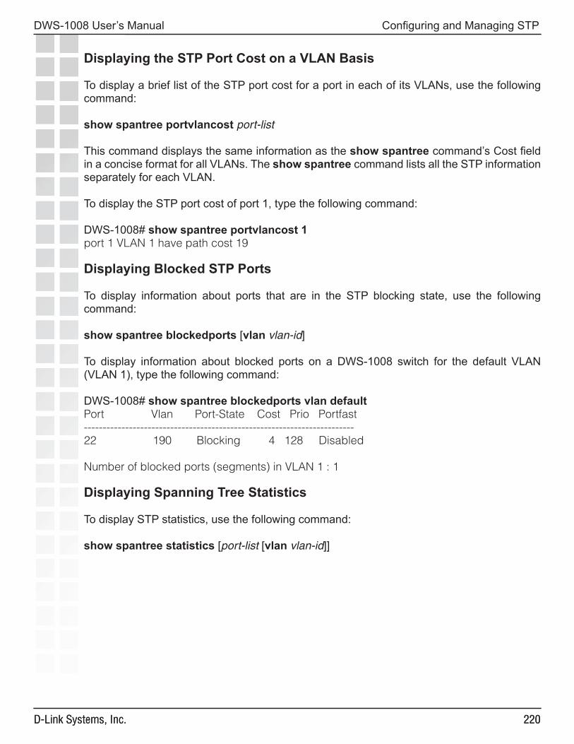
��0
DWS-1008 User’s Manual
D-Link Systems, Inc.
Configuring and Managing STP
��0D-Link Systems, Inc.
Displaying the STP Port Cost on a VLAN Basis
To display a brief list of the STP port cost for a port in each of its VLANs, use the following command:
show spantree portvlancost port-list
This command displays the same information as the show spantree command’s Cost field in a concise format for all VLANs. The show spantree command lists all the STP information separately for each VLAN.
To display the STP port cost of port 1, type the following command:
DWS-1008# show spantree portvlancost 1port 1 VLAN 1 have path cost 19
Displaying Blocked STP Ports
To display information about ports that are in the STP blocking state, use the following command:
show spantree blockedports [vlan vlan-id]
To display information about blocked ports on a DWS-1008 switch for the default VLAN (VLAN 1), type the following command:
DWS-1008# show spantree blockedports vlan defaultPort Vlan Port-State Cost Prio Portfast------------------------------------------------------------------------22 190 Blocking 4 128 Disabled
Number of blocked ports (segments) in VLAN 1 : 1
Displaying Spanning Tree Statistics
To display STP statistics, use the following command:
show spantree statistics [port-list [vlan vlan-id]]
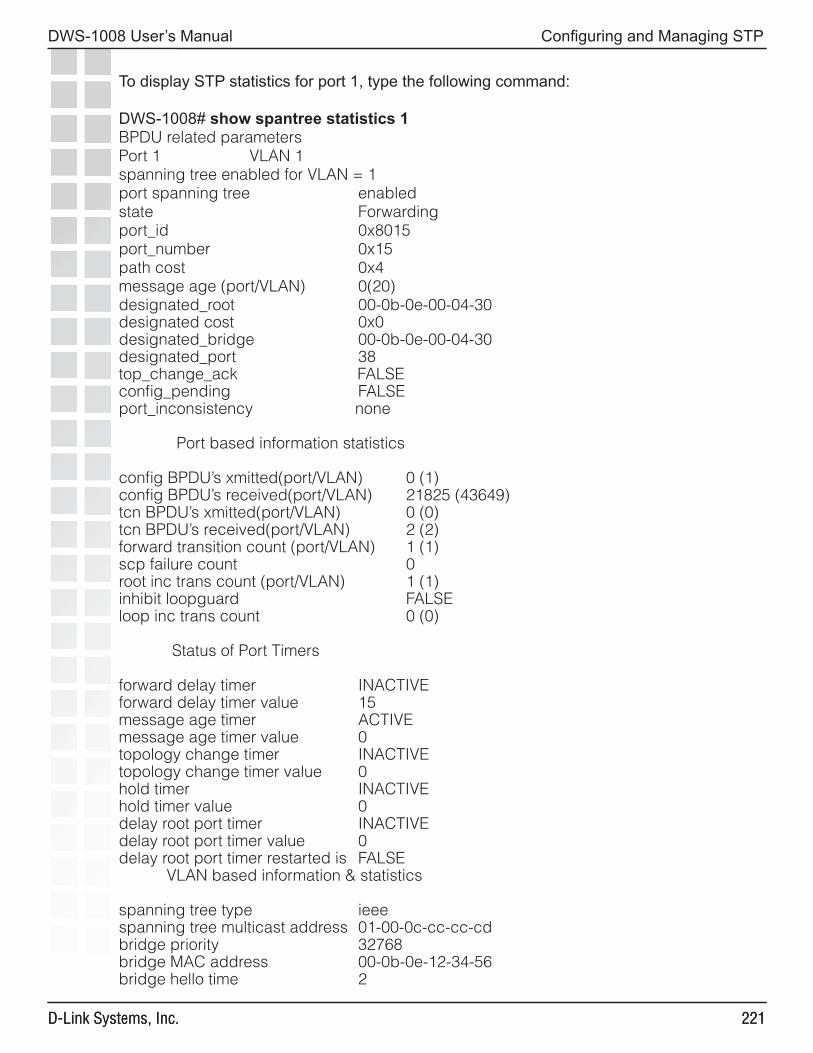
���
DWS-1008 User’s Manual
D-Link Systems, Inc.
Configuring and Managing STP
���D-Link Systems, Inc.
To display STP statistics for port 1, type the following command:
DWS-1008# show spantree statistics 1BPDU related parametersPort 1 VLAN 1spanning tree enabled for VLAN = 1port spanning tree enabledstate Forwardingport_id 0x8015port_number 0x15path cost 0x4message age (port/VLAN) 0(20)designated_root 00-0b-0e-00-04-30designated cost 0x0designated_bridge 00-0b-0e-00-04-30designated_port 38top_change_ack FALSEconfig_pending FALSEport_inconsistency none
Port based information statistics
config BPDU’s xmitted(port/VLAN) 0 (1)config BPDU’s received(port/VLAN) 21825 (43649)tcn BPDU’s xmitted(port/VLAN) 0 (0)tcn BPDU’s received(port/VLAN) 2 (2)forward transition count (port/VLAN) 1 (1)scp failure count 0root inc trans count (port/VLAN) 1 (1)inhibit loopguard FALSEloop inc trans count 0 (0)
Status of Port Timers
forward delay timer INACTIVEforward delay timer value 15message age timer ACTIVEmessage age timer value 0topology change timer INACTIVEtopology change timer value 0hold timer INACTIVEhold timer value 0delay root port timer INACTIVEdelay root port timer value 0delay root port timer restarted is FALSE VLAN based information & statistics
spanning tree type ieeespanning tree multicast address 01-00-0c-cc-cc-cdbridge priority 32768bridge MAC address 00-0b-0e-12-34-56bridge hello time 2

���
DWS-1008 User’s Manual
D-Link Systems, Inc.
Configuring and Managing STP
���D-Link Systems, Inc.
bridge forward delay 15topology change initiator 0last topology change occurred: Tue Jul 01 2003 22:33:36.topology change FALSEtopology change time 35topology change detected FALSEtopology change count 1 topology change last recvd. from 00-0b-0e-02-76-f6
Other port specific info
dynamic max age transition 0port BPDU ok count 21825msg age expiry count 0link loading 0BPDU in processing FALSEnum of similar BPDU’s to process 0received_inferior_bpdu FALSEnext state 0src MAC count 21807total src MAC count 21825curr_src_mac 00-0b-0e-00-04-30next_src_mac 00-0b-0e-02-76-f6
Clearing STP Statistics
To clear the STP statistics counters, use the following command:
clear spantree statistics port-list [vlan vlan-id]
As soon as you enter the command, MSS resets the STP counters for the specified ports or VLANs to 0. The software then begins incrementing the counters again.
Spanning Tree Configuration Scenario
This scenario configures a VLAN named backbone for a switch’s connections to the network backbone, adds ports 2 and 3 to the VLAN, and enables STP on the VLAN to prevent loops.
1. Remove the network cables from ports 2 and 3 or use MSS to disable the ports. This prevents a loop until you complete the STP configuration. To disable the ports and verify the results, type the following commands:
DWS-1008# set port disable 2-3success: set “disable” on port 2-3
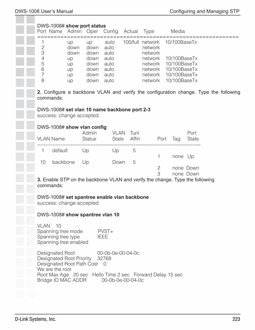
���
DWS-1008 User’s Manual
D-Link Systems, Inc.
Configuring and Managing STP
���D-Link Systems, Inc.
DWS-1008# show port statusPort Name Admin Oper Config Actual Type Media============================================================= 1 up up auto 100/full network 10/100BaseTx 2 down down auto network 3 down down auto network 4 up down auto network 10/100BaseTx 5 up down auto network 10/100BaseTx 6 up down auto network 10/100BaseTx 7 up down auto network 10/100BaseTx 8 up down auto network 10/100BaseTx
2. Configure a backbone VLAN and verify the configuration change. Type the following commands:
DWS-1008# set vlan 10 name backbone port 2-3success: change accepted.
DWS-1008# show vlan config Admin VLAN Tunl PortVLAN Name Status State Affin Port Tag State-------------------------------------------------------------------------------------------------- 1 default Up Up 5 1 none Up 10 backbone Up Down 5 2 none Down 3 none Down3. Enable STP on the backbone VLAN and verify the change. Type the following commands:
DWS-1008# set spantree enable vlan backbonesuccess: change accepted.
DWS-1008# show spantree vlan 10
VLAN 10Spanning tree mode PVST+Spanning tree type IEEESpanning tree enabled
Designated Root 00-0b-0e-00-04-0cDesignated Root Priority 32768Designated Root Path Cost 0We are the rootRoot Max Age 20 sec Hello Time 2 sec Forward Delay 15 secBridge ID MAC ADDR 00-0b-0e-00-04-0c
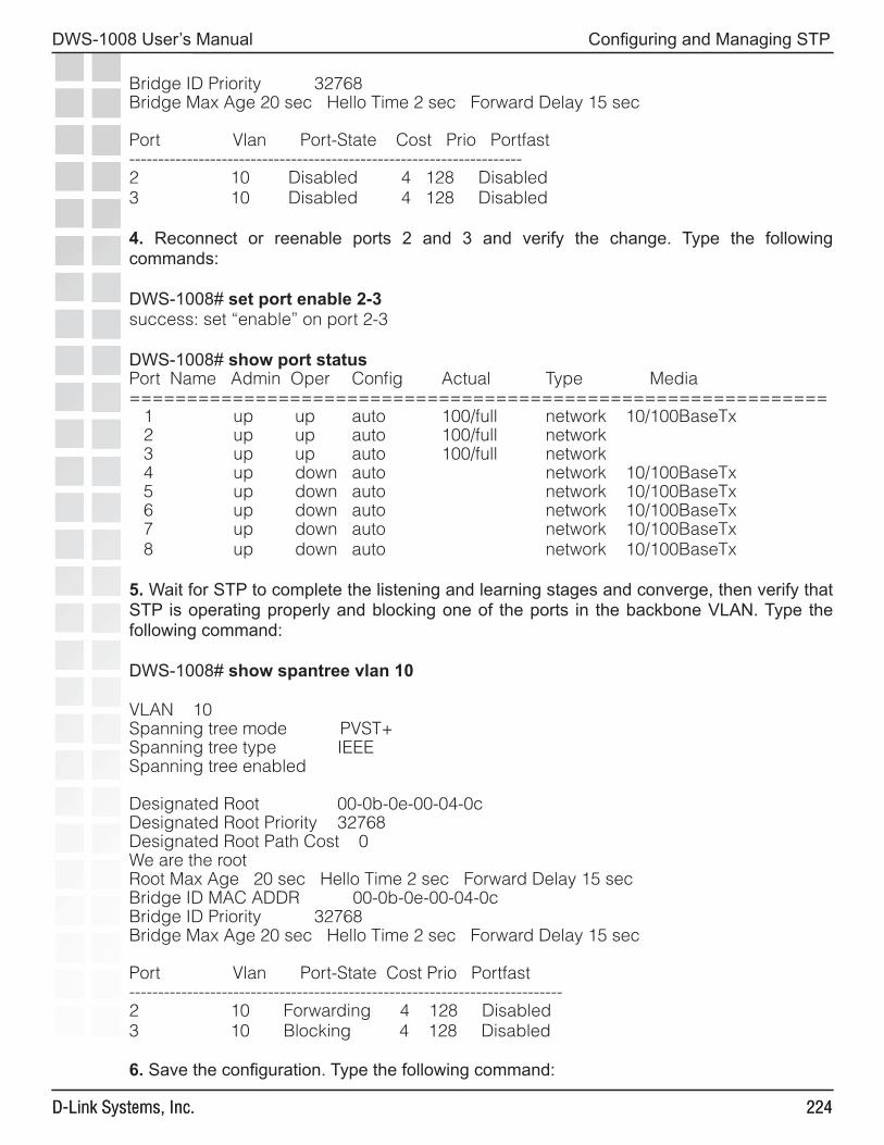
���
DWS-1008 User’s Manual
D-Link Systems, Inc.
Configuring and Managing STP
���D-Link Systems, Inc.
Bridge ID Priority 32768Bridge Max Age 20 sec Hello Time 2 sec Forward Delay 15 sec
Port Vlan Port-State Cost Prio Portfast--------------------------------------------------------------------2 10 Disabled 4 128 Disabled3 10 Disabled 4 128 Disabled
4. Reconnect or reenable ports 2 and 3 and verify the change. Type the following commands:
DWS-1008# set port enable 2-3success: set “enable” on port 2-3
DWS-1008# show port statusPort Name Admin Oper Config Actual Type Media============================================================= 1 up up auto 100/full network 10/100BaseTx 2 up up auto 100/full network 3 up up auto 100/full network 4 up down auto network 10/100BaseTx 5 up down auto network 10/100BaseTx 6 up down auto network 10/100BaseTx 7 up down auto network 10/100BaseTx 8 up down auto network 10/100BaseTx
5. Wait for STP to complete the listening and learning stages and converge, then verify that STP is operating properly and blocking one of the ports in the backbone VLAN. Type the following command:
DWS-1008# show spantree vlan 10
VLAN 10Spanning tree mode PVST+Spanning tree type IEEESpanning tree enabled
Designated Root 00-0b-0e-00-04-0cDesignated Root Priority 32768Designated Root Path Cost 0We are the rootRoot Max Age 20 sec Hello Time 2 sec Forward Delay 15 secBridge ID MAC ADDR 00-0b-0e-00-04-0cBridge ID Priority 32768Bridge Max Age 20 sec Hello Time 2 sec Forward Delay 15 sec
Port Vlan Port-State Cost Prio Portfast---------------------------------------------------------------------------2 10 Forwarding 4 128 Disabled3 10 Blocking 4 128 Disabled
6. Save the configuration. Type the following command:
���
DWS-1008 User’s Manual
D-Link Systems, Inc.
Configuring and Managing IGMP Snooping
Configuring and ManagingIGMP Snooping
Internet Group Management Protocol (IGMP) snooping controls multicast traffic on a DWS-1008 switch by forwarding packets for a multicast group only on the ports that are connected to members of the group. A multicast group is a set of IP hosts that receive traffic addressed to a specific Class D IP address, the group address.
The switch listens for multicast packets and maintains a table of multicast groups, as well as their sources and receivers, based on the traffic. IGMP snooping is enabled by default.
You can configure IGMP snooping parameters and enable or disable the feature on an individual VLAN basis. The current software version supports IGMP versions 1 and 2.
Disabling or Reenabling IGMP Snooping
IGMP snooping is enabled by default. To disable or reenable the feature, use the following command:
set igmp {enable | disable} [vlan vlan-id]
If you do not specify a VLAN ID, the change is applied to all VLANs on the switch.
Disabling or Reenabling Proxy Reporting
Proxy reporting reduces multicast overhead by sending only one report for each active group to the multicast routers, instead of sending a separate report from each multicast receiver. For example, if the switch receives reports from three receivers for multicast group 237.255.255.255, the switch sends only one report for the group to the routers. One report is sufficient to cause the routers to continue sending data for the group. Proxy reporting is enabled by default.
To disable or reenable proxy reporting, use the following command:
set igmp proxy-report {enable | disable} [vlan vlan-id]
Enabling the Pseudo-Querier
The IGMP pseudo-querier enables IGMP snooping to operate in a VLAN that does not have a multicast router to send IGMP general queries to clients.
���
DWS-1008 User’s Manual
D-Link Systems, Inc.
Configuring and Managing IGMP SnoopingDWS-1008 User’s Manual
Note: D-Link recommends that you use the pseudo-querier only when the VLAN contains local multicast traffic sources and no multicast router is servicing the subnet.To enable the pseudo-querier, use the following command:
set igmp querier {enable | disable} [vlan vlan-id]
Changing IGMP Timers
You can change the following IGMP timers:
• Query interval - Number of seconds that elapse between general queries sent by the switch to advertise multicast groups.
• Other-querier-present interval - Number of seconds that the switch waits for a general query to arrive from another querier before electing itself the querier.
• Query response interval - Number of tenths of a second that the switch waits for a receiver to respond to a group-specific query message before removing the receiver from the receiver list for the group.
Note: The query interval, other-querier-present interval, and query response interval are applicable only when the switch is querier for the subnet. For the switch to become the querier, the pseudo-querier feature must be enabled on the switch and the switch must have the lowest IP address among all the devices eligible to become a querier.
• Last member query interval - Number of tenths of a second that the switch waits for a response to a group-specific query after receiving a leave message for that group, before removing the receiver that sent the leave message from the list of receivers for the group. If there are no more receivers for the group, the switch also sends a leave message for the group to multicast routers.
• Robustness value - Number used as a multiplier to adjust the IGMP timers to the amount of traffic loss that occurs on the network. Set the robustness value higher to adjust for more traffic loss.
Changing the Query Interval
To change the IGMP query interval timer, use the following command:
set igmp qi seconds [vlan vlan-id]
For seconds, you can specify a value from 1 through 65,535. The default is 125 seconds.
Changing the Other-Querier-Present Interval
To change the other-querier-present interval, use the following command:
set igmp oqi seconds [vlan vlan-id]
For seconds, you can specify a value from 1 through 65,535. The default is 255 seconds.

���
DWS-1008 User’s Manual
D-Link Systems, Inc.
Configuring and Managing IGMP SnoopingDWS-1008 User’s Manual
Changing the Query Response Interval
To set the query response interval, use the following command:
set igmp qri tenth-seconds [vlan vlan-id]
You can specify a value from 1 through 65,535 tenths of a second. The default is 100 tenths of a second (10 seconds).
Changing the Last Member Query Interval
To set the last member query interval, use the following command:
set igmp lmqi tenth-seconds [vlan vlan-id]
You can specify a value from 1 through 65,535 tenths of a second. The default is 10 tenths of a second (1 second).
Changing Robustness
Robustness adjusts the IGMP timers to the amount of traffic loss that occurs on the network. Set the robustness value higher to adjust for more traffic loss. To change the robustness value, use the following command:
set igmp rv num [vlan vlan-id]
You can specify a value from 2 through 255. The default is 2.
Enabling Router Solicitation
A DWS-1008 switch can search for multicast routers by sending multicast router solicitation messages. This message invites multicast routers that receive the message and that support router solicitation to immediately advertise themselves to the switch. Router solicitation is disabled by default.
The MSS implementation of router solicitation is based on draft-ietf-idmr-igmp-mrdisc-09.txt.To enable or disable multicast router solicitation, use the following command:
set igmp mrsol {enable | disable} [vlan vlan-id]
Changing the Router Solicitation Interval
The default multicast router solicitation interval is 30 seconds. To change the interval, use the following command:
set igmp mrsol mrsi seconds [vlan vlan-id]
You can specify 1 through 65,535 seconds. The default is 30 seconds.
���
DWS-1008 User’s Manual
D-Link Systems, Inc.
Configuring and Managing IGMP SnoopingDWS-1008 User’s Manual
Configuring Static Multicast Ports
A DWS-1008 switch learns about multicast routers and receivers from multicast traffic it receives from those devices. When the switch receives traffic from a multicast router or receiver, the switch adds the port that received the traffic as a multicast router or receiver port. The switch forwards traffic to multicast routers only on the multicast router ports and forwards traffic to multicast receivers only on the multicast receiver ports.
The router and receiver ports that the switch learns based on multicast traffic age out if they are unused. You can add network ports as static multicast router ports or multicast receiver ports. Ports you add do not age out.
Note. You cannot add access ports or wired authentication ports as static multicast ports. However, MSS can dynamically add these port types to the list of multicast ports based on multicast traffic.
Adding or Removing a Static Multicast Router Port
To add or remove a static multicast router port, use the following command:
set igmp mrouter port port-list enable | disable
Adding or Removing a Static Multicast Receiver Port
To add a static multicast receiver port, use the following command:
set igmp receiver port port-list enable | disable
Displaying Multicast Information
You can use the CLI to display the following IGMP snooping information:
• Multicast configuration information and statistics• Multicast queriers• Multicast routers• Multicast receivers
Displaying Multicast Configuration Information and Statistics
To display multicast configuration information and statistics, use the following command:
show igmp [vlan vlan-id]
The show igmp command displays the IGMP snooping state, the settings of all multicast parameters you can configure, and multicast statistics.
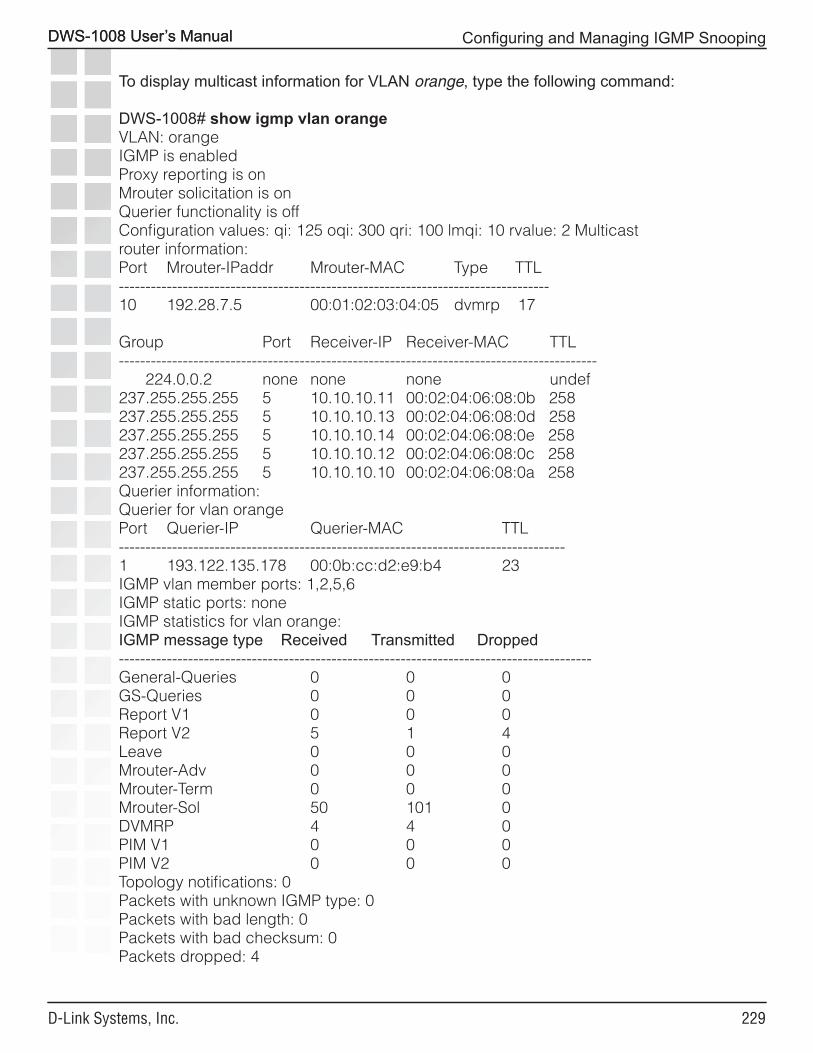
���
DWS-1008 User’s Manual
D-Link Systems, Inc.
Configuring and Managing IGMP SnoopingDWS-1008 User’s Manual
To display multicast information for VLAN orange, type the following command:
DWS-1008# show igmp vlan orangeVLAN: orangeIGMP is enabledProxy reporting is onMrouter solicitation is onQuerier functionality is offConfiguration values: qi: 125 oqi: 300 qri: 100 lmqi: 10 rvalue: 2 Multicastrouter information:Port Mrouter-IPaddr Mrouter-MAC Type TTL---------------------------------------------------------------------------------10 192.28.7.5 00:01:02:03:04:05 dvmrp 17
Group Port Receiver-IP Receiver-MAC TTL------------------------------------------------------------------------------------------ 224.0.0.2 none none none undef237.255.255.255 5 10.10.10.11 00:02:04:06:08:0b 258237.255.255.255 5 10.10.10.13 00:02:04:06:08:0d 258237.255.255.255 5 10.10.10.14 00:02:04:06:08:0e 258237.255.255.255 5 10.10.10.12 00:02:04:06:08:0c 258237.255.255.255 5 10.10.10.10 00:02:04:06:08:0a 258Querier information:Querier for vlan orangePort Querier-IP Querier-MAC TTL------------------------------------------------------------------------------------1 193.122.135.178 00:0b:cc:d2:e9:b4 23IGMP vlan member ports: 1,2,5,6IGMP static ports: noneIGMP statistics for vlan orange:IGMP message type Received Transmitted Dropped-----------------------------------------------------------------------------------------General-Queries 0 0 0GS-Queries 0 0 0Report V1 0 0 0Report V2 5 1 4Leave 0 0 0Mrouter-Adv 0 0 0Mrouter-Term 0 0 0Mrouter-Sol 50 101 0DVMRP 4 4 0PIM V1 0 0 0PIM V2 0 0 0Topology notifications: 0Packets with unknown IGMP type: 0Packets with bad length: 0Packets with bad checksum: 0Packets dropped: 4
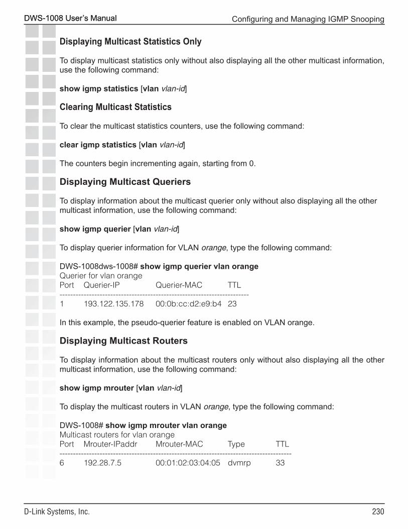
��0
DWS-1008 User’s Manual
D-Link Systems, Inc.
Configuring and Managing IGMP SnoopingDWS-1008 User’s Manual
Displaying Multicast Statistics Only
To display multicast statistics only without also displaying all the other multicast information, use the following command:
show igmp statistics [vlan vlan-id]
Clearing Multicast Statistics
To clear the multicast statistics counters, use the following command:
clear igmp statistics [vlan vlan-id]
The counters begin incrementing again, starting from 0.
Displaying Multicast Queriers
To display information about the multicast querier only without also displaying all the other multicast information, use the following command:
show igmp querier [vlan vlan-id]
To display querier information for VLAN orange, type the following command:
DWS-1008dws-1008# show igmp querier vlan orangeQuerier for vlan orangePort Querier-IP Querier-MAC TTL-----------------------------------------------------------------------1 193.122.135.178 00:0b:cc:d2:e9:b4 23
In this example, the pseudo-querier feature is enabled on VLAN orange.
Displaying Multicast Routers
To display information about the multicast routers only without also displaying all the other multicast information, use the following command:
show igmp mrouter [vlan vlan-id]
To display the multicast routers in VLAN orange, type the following command:
DWS-1008# show igmp mrouter vlan orangeMulticast routers for vlan orangePort Mrouter-IPaddr Mrouter-MAC Type TTL---------------------------------------------------------------------------------------6 192.28.7.5 00:01:02:03:04:05 dvmrp 33
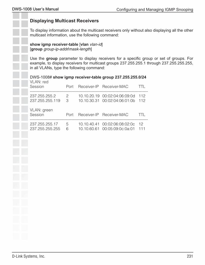
���
DWS-1008 User’s Manual
D-Link Systems, Inc.
Configuring and Managing IGMP SnoopingDWS-1008 User’s Manual
Displaying Multicast Receivers
To display information about the multicast receivers only without also displaying all the other multicast information, use the following command:
show igmp receiver-table [vlan vlan-id] [group group-ip-addr/mask-length]
Use the group parameter to display receivers for a specific group or set of groups. For example, to display receivers for multicast groups 237.255.255.1 through 237.255.255.255, in all VLANs, type the following command:
DWS-1008# show igmp receiver-table group 237.255.255.0/24VLAN: redSession Port Receiver-IP Receiver-MAC TTL----------------------------------------------------------------------------------------237.255.255.2 2 10.10.20.19 00:02:04:06:09:0d 112237.255.255.119 3 10.10.30.31 00:02:04:06:01:0b 112
VLAN: greenSession Port Receiver-IP Receiver-MAC TTL----------------------------------------------------------------------------------------237.255.255.17 5 10.10.40.41 00:02:06:08:02:0c 12237.255.255.255 6 10.10.60.61 00:05:09:0c:0a:01 111

���
DWS-1008 User’s Manual
D-Link Systems, Inc.
Configuring and Managing Security ACLs
Configuring and ManagingSecurity ACLs
About Security Access Control ListsA security access control list (ACL) filters packets for the purpose of discarding them, permitting them, or permitting them with modification (marking) for class-of-service (CoS) priority treatment. A typical use of security ACLs is to enable users to send and receive packets within the local intranet, but restrict incoming packets to the server in which confidential salary information is stored.
D-Link provides a very powerful mapping application for security ACLs. In addition to being assigned to physical ports, VLANs, virtual ports in a VLAN, or Distributed APs, ACLs can be mapped dynamically to a user’s session, based on authorization information passed back from the AAA server during the user authentication process.
Security ACL Filters
A security ACL filters packets to restrict or permit network traffic. These filters can then be mapped by name to authenticated users, ports, VLANs, virtual ports, or Distributed APs. You can also assign a class-of-service (CoS) level that marks the packets matching the filter for priority handling.
A security ACL contains an ordered list of rules called access control entries (ACEs), which specify how to handle packets. An ACE contains an action that can deny the traffic, permit the traffic, or permit the traffic and apply to it a specific CoS level of packet handling. The filter can include source and destination IP address information along with other Layer 3 and Layer 4 parameters. Action is taken only if the packet matches the filter.
The order in which ACEs are listed in an ACL is important. MSS applies ACEs that are higher in the list before ACEs lower in the list. An implicit “deny all” rule is always processed as the last ACE of an ACL. If a packet matches no ACE in the entire mapped ACL, the packet is rejected. If the ACL does not contain at least one ACE that permits access, no traffic is allowed.
Plan your security ACL maps to ports, VLANs, virtual ports, and Distributed APs so that only one security ACL filters a given flow of packets. If more than one security ACL filters the same traffic, MSS applies only the first ACL match and ignores any other matches. Security ACLs that are mapped to users have precedence over ACLs mapped to ports, VLANs, virtual ports, or Distributed APs.
You cannot perform ACL functions that include permitting, denying, or marking with a Class of Service (CoS) level on packets with a multicast or broadcast destination address.
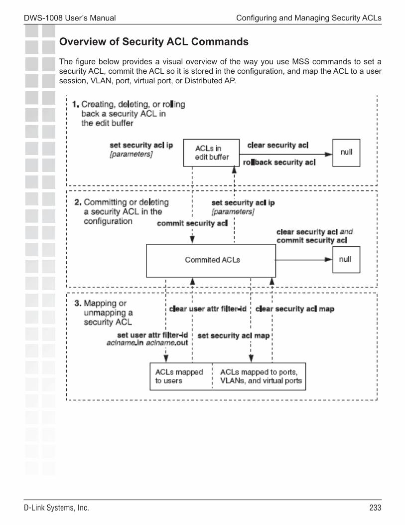
���
DWS-1008 User’s Manual
D-Link Systems, Inc.
Configuring and Managing Security ACLs
Overview of Security ACL Commands
The figure below provides a visual overview of the way you use MSS commands to set a security ACL, commit the ACL so it is stored in the configuration, and map the ACL to a user session, VLAN, port, virtual port, or Distributed AP.
���
DWS-1008 User’s Manual
D-Link Systems, Inc.
Configuring and Managing Security ACLs
Creating and Committing a Security ACL
The security ACLs you create can filter packets by source address, IP protocol, port type, and other characteristics. When you configure an ACE for a security ACL, MSS stores the ACE in the edit buffer until you commit the ACL to be saved to the permanent configuration. You must commit a security ACL before you can apply it to an authenticated user’s session or map it to a port, VLAN, virtual port, or Distributed AP. Every security ACL must have a name.
Setting a Source IP ACL
You can create an ACE that filters packets based on the source IP address and optionally applies CoS packet handling. (For CoS details, see Class of Service.) You can also determine where the ACE is placed in the security ACL by using the before editbuffer-index or modify editbuffer-index variables with an index number. You can use the hits counter to track how many packets the ACL filters.
The simplest security ACL permits or denies packets from a source IP address:
set security acl ip acl-name {permit [cos cos] | deny} source-ip-addr mask[before editbuffer-index | modify editbuffer-index] [hits]
For example, to create ACL acl-1 that permits all packets from IP address 192.168.1.4, type the following command:
DWS-1008# set security acl ip acl-1 permit 192.168.1.4 0.0.0.0
With the following basic security ACL command, you can specify any of the protocols supported by MSS:
set security acl ip acl-name {permit [cos cos] | deny} {protocol} {source-ip-addr mask destination-ip-addr mask} [precedence precedence] [tos tos] [before editbuffer-index | modify editbuffer-index] [hits]
The following sample security ACL permits all Generic Routing Encapsulation (GRE) packets from source IP address 192.168.1.11 to destination IP address 192.168.1.15, with a precedence level of 0 (routine), and a type-of-service (TOS) level of 0 (normal). GRE is protocol number 47.
DWS-1008# set security acl ip acl-2 permit cos 2 47 192.168.1.11 0.0.0.0 192.168.1.15 0.0.0.0 precedence 0 tos 0 hits
The security ACL acl-2 described above also applies the CoS level 2 (medium priority) to the permitted packets. (For CoS details, see Class of Service.) The keyword hits counts the number of times this ACL affects packet traffic.
The table on the next page lists common IP protocol numbers.
���
DWS-1008 User’s Manual
D-Link Systems, Inc.
Configuring and Managing Security ACLs
Common IP Protocol Numbers
Number IP Protocol1 Internet Message Control Protocol (ICMP)2 Internet Group Management Protocol (IGMP)6 Transmission Control Protocol (TCP)9 Any private interior gateway (used by Cisco for Internet
Gateway Routing Protocol)17 User Datagram Protocol (UDP)46 Resource Reservation Protocol (RSVP)47 Generic Routing Encapsulation (GRE) protocol50 Encapsulation Security Payload for IPSec (IPSec-ESP)51 Authentication Header for IPSec (IPSec-AH)55 IP Mobility (Mobile IP)88 Enhanced Interior Gateway Routing Protocol (EIGRP)89 Open Shortest Path First (OSPF) protocol103 Protocol Independent Multicast (PIM) protocol112 Virtual Router Redundancy Protocol (VRRP)115 Layer Two Tunneling Protocol (L2TP)
Wildcard Masks
When you specify source and destination IP addresses in an ACE, you must also include a mask for each in the form source-ip-addr mask and destination-ip-addr mask.
The mask is a wildcard mask. The security ACL checks the bits in IP addresses that correspond to any 0s (zeros) in the mask, but does not check the bits that correspond to 1s (ones) in the mask. Specify the IP address and wildcard mask in dotted decimal notation. For example, the IP address and wildcard mask 10.0.0.0 and 0.255.255.255 match all IP addresses that begin with 10 in the first octet.
���
DWS-1008 User’s Manual
D-Link Systems, Inc.
Configuring and Managing Security ACLs
Class of Service
Class-of-service (CoS) assignment determines the priority treatment of packets transmitted by a DWS-1008 switch, corresponding to a forwarding queue on the AP. The table below shows the results of CoS priorities you assign in security ACLs.
Class-of-Service (CoS) Packet Handling
WMM Priority DesiredCLI CoS Value to Enter
Background 1 or 2Best effort 0 or 3Video 4 or 5 Voice 6 or 7
AP forwarding prioritization occurs automatically for Wi-Fi Multimedia (WMM) traffic. You do not need to configure ACLs to provide WMM prioritization. For non-WMM devices, you can provide AP forwarding prioritization by configuring ACLs.
If you disable WMM, AP forwarding prioritization is optimized for SpectraLink Voice Priority (SVP) instead of WMM, and the AP does not tag packets it sends to the switch.
If you plan to use SVP or another non-WMM type of prioritization, you must configure ACLs to tag the packets.Optionally, for WMM or non-WMM traffic, you can use ACLs to change the priority of traffic sent to an AP or VLAN. Setting an ICMP ACL
With the following command, you can use security ACLs to set Internet Control Message Protocol (ICMP) parameters for the ping command:
set security acl ip acl-name {permit [cos cos] | deny} icmp {source-ip-addr mask destination-ip-addr mask} [type icmp-type] [code icmp-code] [precedence precedence] [tos tos] [before editbuffer-index | modify editbuffer-index] [hits]
An ICMP ACL can filter packets by source and destination IP address, TOS level, precedence, ICMP type, and ICMP code. For example, the following command permits all ICMP packets coming from 192.168.1.3 and going to 192.168.1.4 that also meet the following conditions:
• ICMP type is 11 (Time Exceeded).• ICMP code is 0 (Time to Live Exceeded).• Type-of-service level is 12 (minimum delay plus maximum throughput).• Precedence is 7 (network control).
DWS-1008# set security acl ip acl-3 permit icmp 192.168.1.3 0.0.0.0 192.168.1.4 0.0.0.0 type 11 code 0 precedence 7 tos 12 before 1 hits
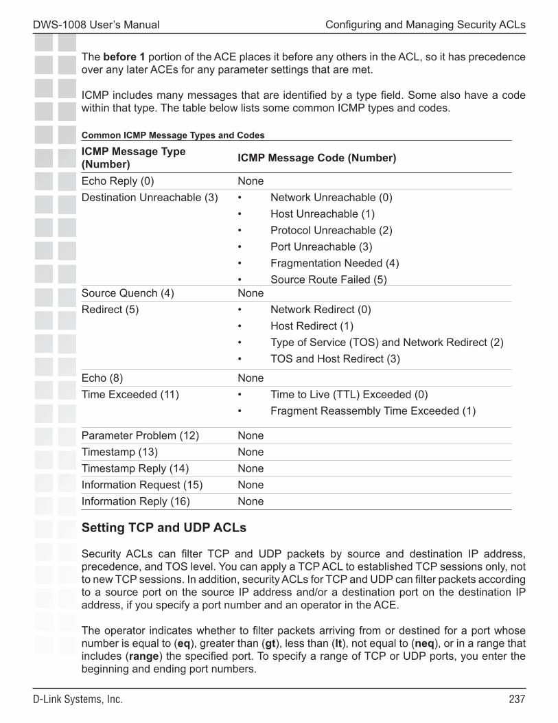
���
DWS-1008 User’s Manual
D-Link Systems, Inc.
Configuring and Managing Security ACLs
The before 1 portion of the ACE places it before any others in the ACL, so it has precedence over any later ACEs for any parameter settings that are met.
ICMP includes many messages that are identified by a type field. Some also have a code within that type. The table below lists some common ICMP types and codes.
Common ICMP Message Types and Codes
ICMP Message Type (Number) ICMP Message Code (Number)
Echo Reply (0) NoneDestination Unreachable (3) • Network Unreachable (0)
• Host Unreachable (1)• Protocol Unreachable (2)• Port Unreachable (3)• Fragmentation Needed (4)• Source Route Failed (5)
Source Quench (4) NoneRedirect (5) • Network Redirect (0)
• Host Redirect (1)• Type of Service (TOS) and Network Redirect (2)• TOS and Host Redirect (3)
Echo (8) NoneTime Exceeded (11) • Time to Live (TTL) Exceeded (0)
• Fragment Reassembly Time Exceeded (1)
Parameter Problem (12) NoneTimestamp (13) NoneTimestamp Reply (14) NoneInformation Request (15) NoneInformation Reply (16) None
Setting TCP and UDP ACLs
Security ACLs can filter TCP and UDP packets by source and destination IP address, precedence, and TOS level. You can apply a TCP ACL to established TCP sessions only, not to new TCP sessions. In addition, security ACLs for TCP and UDP can filter packets according to a source port on the source IP address and/or a destination port on the destination IP address, if you specify a port number and an operator in the ACE.
The operator indicates whether to filter packets arriving from or destined for a port whose number is equal to (eq), greater than (gt), less than (lt), not equal to (neq), or in a range that includes (range) the specified port. To specify a range of TCP or UDP ports, you enter the beginning and ending port numbers.
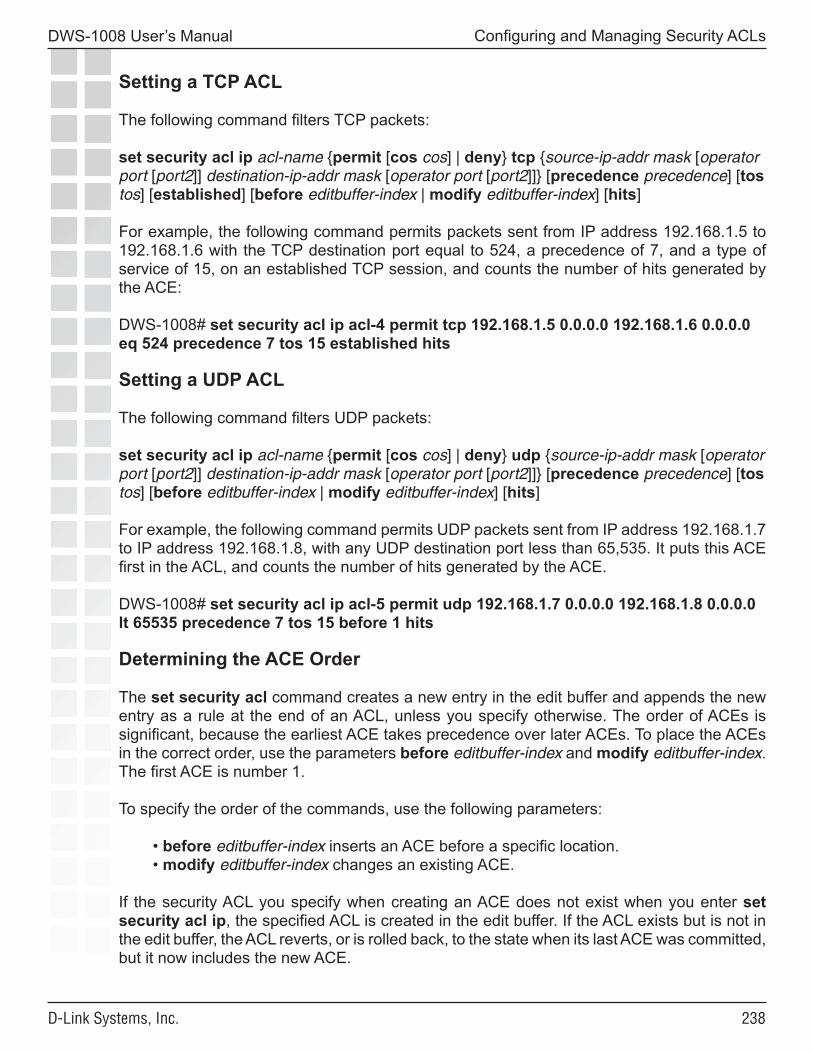
���
DWS-1008 User’s Manual
D-Link Systems, Inc.
Configuring and Managing Security ACLs
Setting a TCP ACL
The following command filters TCP packets:
set security acl ip acl-name {permit [cos cos] | deny} tcp {source-ip-addr mask [operator port [port2]] destination-ip-addr mask [operator port [port2]]} [precedence precedence] [tos tos] [established] [before editbuffer-index | modify editbuffer-index] [hits]
For example, the following command permits packets sent from IP address 192.168.1.5 to 192.168.1.6 with the TCP destination port equal to 524, a precedence of 7, and a type of service of 15, on an established TCP session, and counts the number of hits generated by the ACE:
DWS-1008# set security acl ip acl-4 permit tcp 192.168.1.5 0.0.0.0 192.168.1.6 0.0.0.0 eq 524 precedence 7 tos 15 established hits
Setting a UDP ACL
The following command filters UDP packets:
set security acl ip acl-name {permit [cos cos] | deny} udp {source-ip-addr mask [operator port [port2]] destination-ip-addr mask [operator port [port2]]} [precedence precedence] [tos tos] [before editbuffer-index | modify editbuffer-index] [hits]
For example, the following command permits UDP packets sent from IP address 192.168.1.7 to IP address 192.168.1.8, with any UDP destination port less than 65,535. It puts this ACE first in the ACL, and counts the number of hits generated by the ACE.
DWS-1008# set security acl ip acl-5 permit udp 192.168.1.7 0.0.0.0 192.168.1.8 0.0.0.0 lt 65535 precedence 7 tos 15 before 1 hits
Determining the ACE Order
The set security acl command creates a new entry in the edit buffer and appends the new entry as a rule at the end of an ACL, unless you specify otherwise. The order of ACEs is significant, because the earliest ACE takes precedence over later ACEs. To place the ACEs in the correct order, use the parameters before editbuffer-index and modify editbuffer-index. The first ACE is number 1.
To specify the order of the commands, use the following parameters:
• before editbuffer-index inserts an ACE before a specific location. • modify editbuffer-index changes an existing ACE.
If the security ACL you specify when creating an ACE does not exist when you enter set security acl ip, the specified ACL is created in the edit buffer. If the ACL exists but is not in the edit buffer, the ACL reverts, or is rolled back, to the state when its last ACE was committed, but it now includes the new ACE.
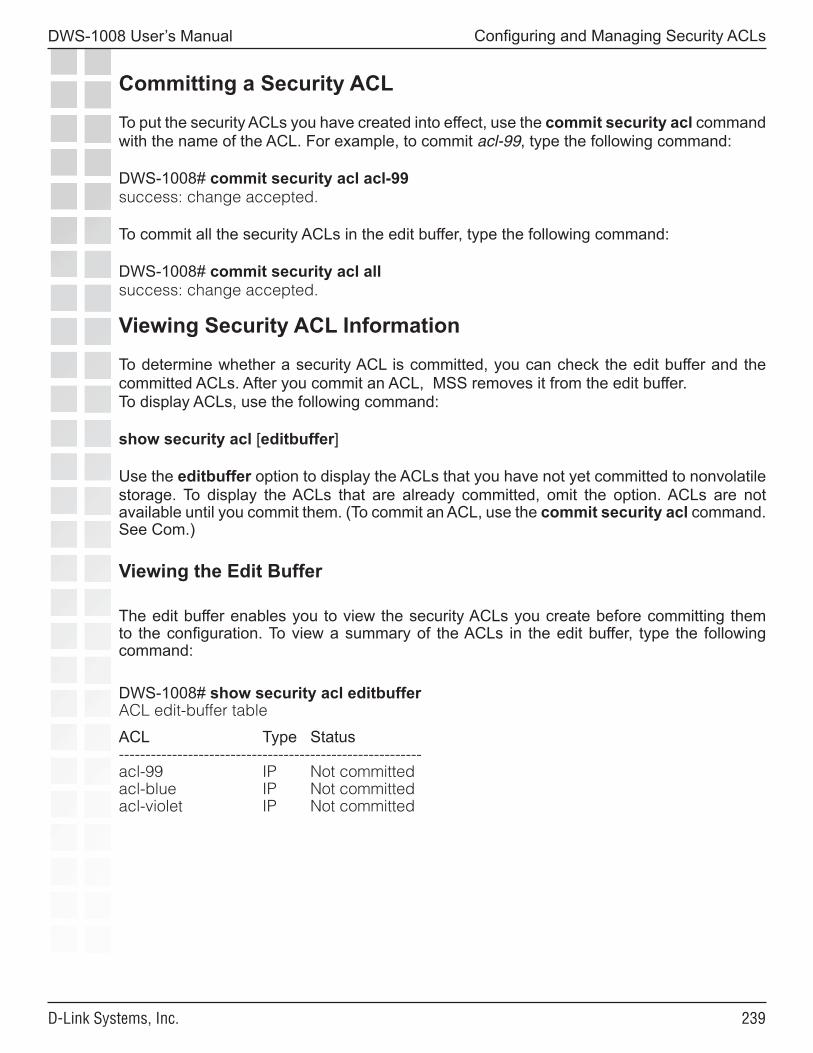
���
DWS-1008 User’s Manual
D-Link Systems, Inc.
Configuring and Managing Security ACLs
Committing a Security ACL
To put the security ACLs you have created into effect, use the commit security acl command with the name of the ACL. For example, to commit acl-99, type the following command:
DWS-1008# commit security acl acl-99success: change accepted.
To commit all the security ACLs in the edit buffer, type the following command:
DWS-1008# commit security acl allsuccess: change accepted.
Viewing Security ACL Information
To determine whether a security ACL is committed, you can check the edit buffer and the committed ACLs. After you commit an ACL, MSS removes it from the edit buffer.To display ACLs, use the following command:
show security acl [editbuffer]
Use the editbuffer option to display the ACLs that you have not yet committed to nonvolatile storage. To display the ACLs that are already committed, omit the option. ACLs are not available until you commit them. (To commit an ACL, use the commit security acl command. See Com.)
Viewing the Edit Buffer
The edit buffer enables you to view the security ACLs you create before committing them to the configuration. To view a summary of the ACLs in the edit buffer, type the following command:
DWS-1008# show security acl editbufferACL edit-buffer table
ACL Type Status---------------------------------------------------------acl-99 IP Not committedacl-blue IP Not committedacl-violet IP Not committed
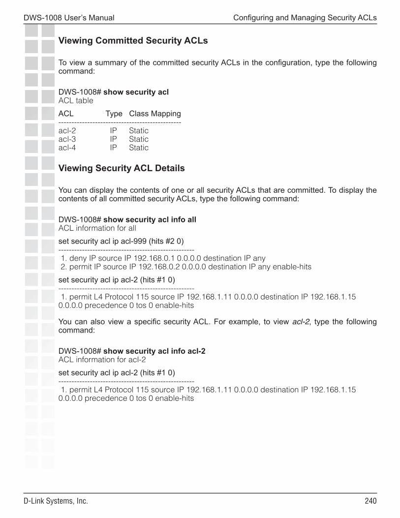
��0
DWS-1008 User’s Manual
D-Link Systems, Inc.
Configuring and Managing Security ACLs
Viewing Committed Security ACLs
To view a summary of the committed security ACLs in the configuration, type the following command:
DWS-1008# show security aclACL table
ACL Type Class Mapping-----------------------------------------------acl-2 IP Staticacl-3 IP Staticacl-4 IP Static
Viewing Security ACL Details
You can display the contents of one or all security ACLs that are committed. To display the contents of all committed security ACLs, type the following command:
DWS-1008# show security acl info allACL information for all
set security acl ip acl-999 (hits #2 0)---------------------------------------------------- 1. deny IP source IP 192.168.0.1 0.0.0.0 destination IP any 2. permit IP source IP 192.168.0.2 0.0.0.0 destination IP any enable-hits
set security acl ip acl-2 (hits #1 0)---------------------------------------------------- 1. permit L4 Protocol 115 source IP 192.168.1.11 0.0.0.0 destination IP 192.168.1.15 0.0.0.0 precedence 0 tos 0 enable-hits
You can also view a specific security ACL. For example, to view acl-2, type the following command:
DWS-1008# show security acl info acl-2ACL information for acl-2
set security acl ip acl-2 (hits #1 0)---------------------------------------------------- 1. permit L4 Protocol 115 source IP 192.168.1.11 0.0.0.0 destination IP 192.168.1.15 0.0.0.0 precedence 0 tos 0 enable-hits
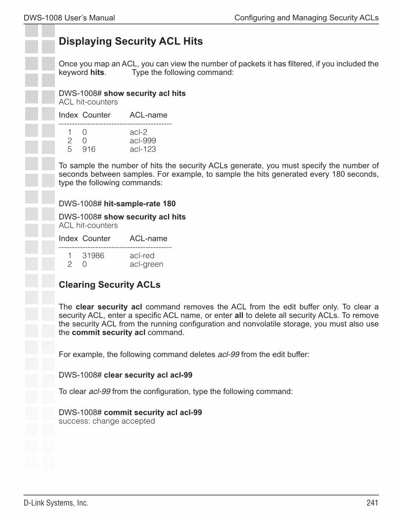
���
DWS-1008 User’s Manual
D-Link Systems, Inc.
Configuring and Managing Security ACLs
Displaying Security ACL Hits
Once you map an ACL, you can view the number of packets it has filtered, if you included the keyword hits. Type the following command:
DWS-1008# show security acl hitsACL hit-counters
Index Counter ACL-name------------------------------------------- 1 0 acl-2 2 0 acl-999 5 916 acl-123
To sample the number of hits the security ACLs generate, you must specify the number of seconds between samples. For example, to sample the hits generated every 180 seconds, type the following commands:
DWS-1008# hit-sample-rate 180DWS-1008# show security acl hitsACL hit-counters
Index Counter ACL-name------------------------------------------- 1 31986 acl-red 2 0 acl-green
Clearing Security ACLs
The clear security acl command removes the ACL from the edit buffer only. To clear a security ACL, enter a specific ACL name, or enter all to delete all security ACLs. To remove the security ACL from the running configuration and nonvolatile storage, you must also use the commit security acl command.
For example, the following command deletes acl-99 from the edit buffer:
DWS-1008# clear security acl acl-99
To clear acl-99 from the configuration, type the following command:
DWS-1008# commit security acl acl-99success: change accepted
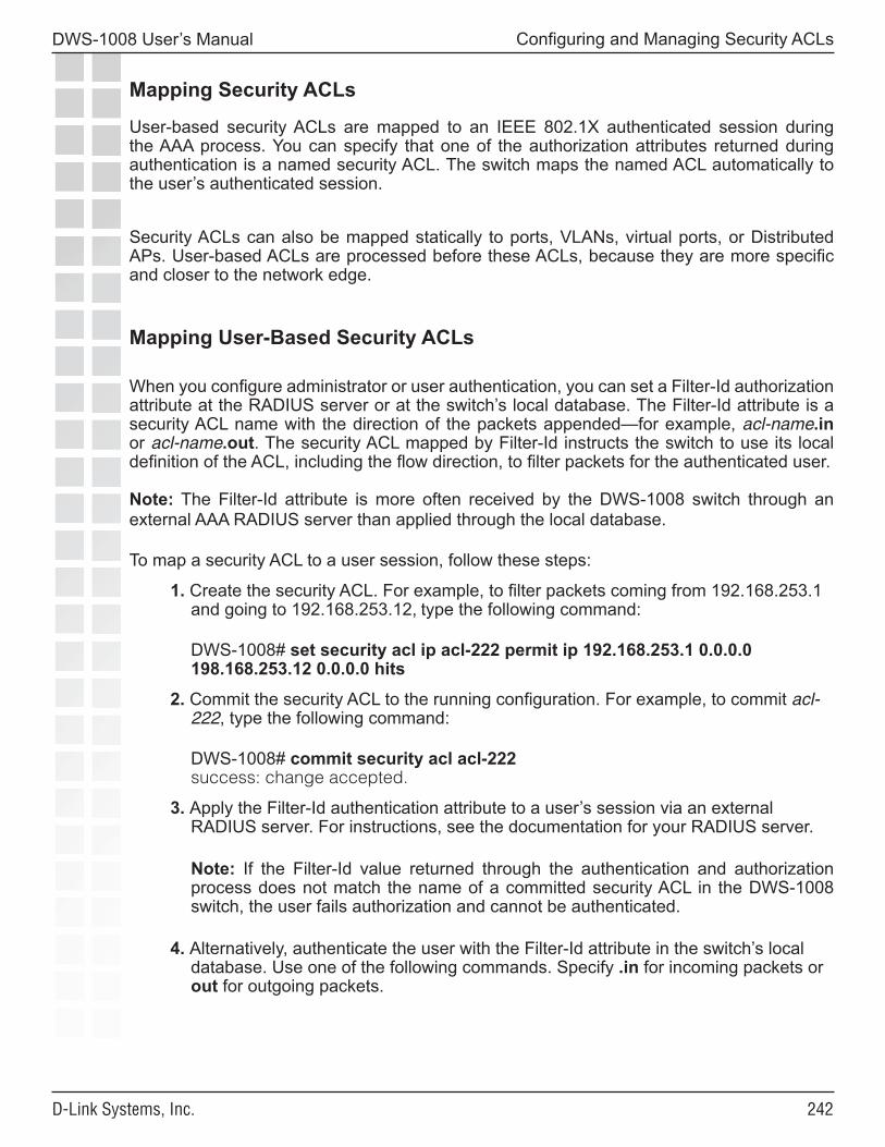
���
DWS-1008 User’s Manual
D-Link Systems, Inc.
Configuring and Managing Security ACLs
Mapping Security ACLs
User-based security ACLs are mapped to an IEEE 802.1X authenticated session during the AAA process. You can specify that one of the authorization attributes returned during authentication is a named security ACL. The switch maps the named ACL automatically to the user’s authenticated session.
Security ACLs can also be mapped statically to ports, VLANs, virtual ports, or Distributed APs. User-based ACLs are processed before these ACLs, because they are more specific and closer to the network edge.
Mapping User-Based Security ACLs
When you configure administrator or user authentication, you can set a Filter-Id authorization attribute at the RADIUS server or at the switch’s local database. The Filter-Id attribute is a security ACL name with the direction of the packets appended—for example, acl-name.in or acl-name.out. The security ACL mapped by Filter-Id instructs the switch to use its local definition of the ACL, including the flow direction, to filter packets for the authenticated user.
Note: The Filter-Id attribute is more often received by the DWS-1008 switch through an external AAA RADIUS server than applied through the local database.
To map a security ACL to a user session, follow these steps:
1. Create the security ACL. For example, to filter packets coming from 192.168.253.1 and going to 192.168.253.12, type the following command:
DWS-1008# set security acl ip acl-222 permit ip 192.168.253.1 0.0.0.0 198.168.253.12 0.0.0.0 hits
2. Commit the security ACL to the running configuration. For example, to commit acl-222, type the following command:
DWS-1008# commit security acl acl-222 success: change accepted.
3. Apply the Filter-Id authentication attribute to a user’s session via an external RADIUS server. For instructions, see the documentation for your RADIUS server.
Note: If the Filter-Id value returned through the authentication and authorization process does not match the name of a committed security ACL in the DWS-1008 switch, the user fails authorization and cannot be authenticated.
4. Alternatively, authenticate the user with the Filter-Id attribute in the switch’s local database. Use one of the following commands. Specify .in for incoming packets or out for outgoing packets.
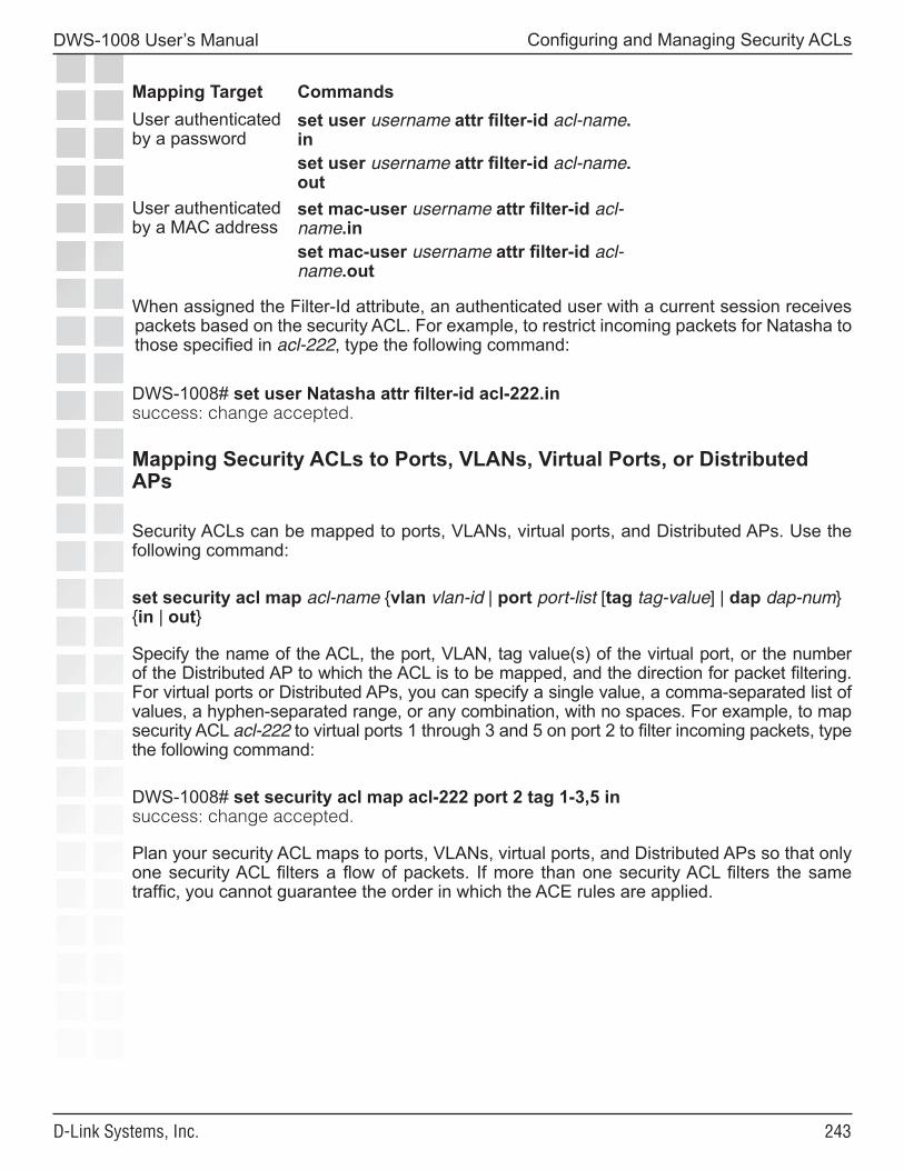
���
DWS-1008 User’s Manual
D-Link Systems, Inc.
Configuring and Managing Security ACLs
Mapping Target CommandsUser authenticated by a password
set user username attr filter-id acl-name.inset user username attr filter-id acl-name.out
User authenticated by a MAC address
set mac-user username attr filter-id acl-name.inset mac-user username attr filter-id acl-name.out
When assigned the Filter-Id attribute, an authenticated user with a current session receives packets based on the security ACL. For example, to restrict incoming packets for Natasha to those specified in acl-222, type the following command:
DWS-1008# set user Natasha attr filter-id acl-222.insuccess: change accepted.
Mapping Security ACLs to Ports, VLANs, Virtual Ports, or Distributed APs
Security ACLs can be mapped to ports, VLANs, virtual ports, and Distributed APs. Use the following command:
set security acl map acl-name {vlan vlan-id | port port-list [tag tag-value] | dap dap-num} {in | out}
Specify the name of the ACL, the port, VLAN, tag value(s) of the virtual port, or the number of the Distributed AP to which the ACL is to be mapped, and the direction for packet filtering. For virtual ports or Distributed APs, you can specify a single value, a comma-separated list of values, a hyphen-separated range, or any combination, with no spaces. For example, to map security ACL acl-222 to virtual ports 1 through 3 and 5 on port 2 to filter incoming packets, type the following command:
DWS-1008# set security acl map acl-222 port 2 tag 1-3,5 insuccess: change accepted.
Plan your security ACL maps to ports, VLANs, virtual ports, and Distributed APs so that only one security ACL filters a flow of packets. If more than one security ACL filters the same traffic, you cannot guarantee the order in which the ACE rules are applied.
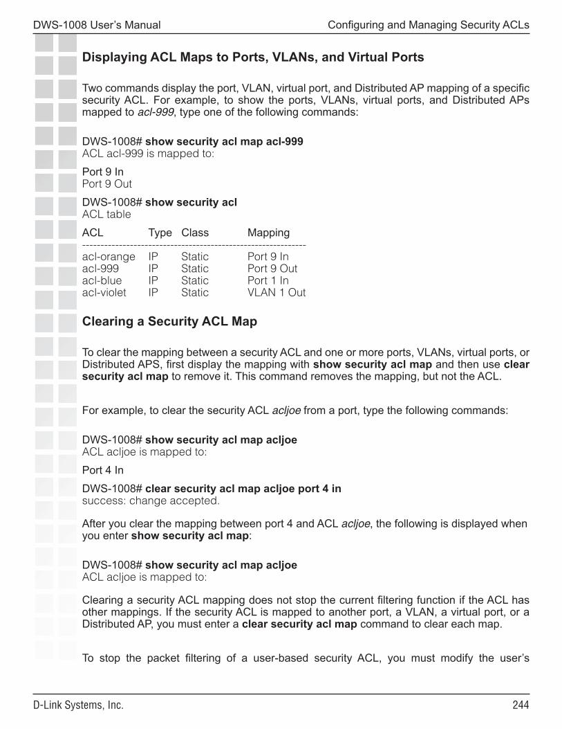
���
DWS-1008 User’s Manual
D-Link Systems, Inc.
Configuring and Managing Security ACLs
Displaying ACL Maps to Ports, VLANs, and Virtual Ports
Two commands display the port, VLAN, virtual port, and Distributed AP mapping of a specific security ACL. For example, to show the ports, VLANs, virtual ports, and Distributed APs mapped to acl-999, type one of the following commands:
DWS-1008# show security acl map acl-999ACL acl-999 is mapped to:
Port 9 InPort 9 Out
DWS-1008# show security aclACL table
ACL Type Class Mapping-------------------------------------------------------------acl-orange IP Static Port 9 Inacl-999 IP Static Port 9 Out acl-blue IP Static Port 1 Inacl-violet IP Static VLAN 1 Out
Clearing a Security ACL Map
To clear the mapping between a security ACL and one or more ports, VLANs, virtual ports, or Distributed APS, first display the mapping with show security acl map and then use clear security acl map to remove it. This command removes the mapping, but not the ACL.
For example, to clear the security ACL acljoe from a port, type the following commands:
DWS-1008# show security acl map acljoeACL acljoe is mapped to:
Port 4 In
DWS-1008# clear security acl map acljoe port 4 insuccess: change accepted.
After you clear the mapping between port 4 and ACL acljoe, the following is displayed when you enter show security acl map:
DWS-1008# show security acl map acljoeACL acljoe is mapped to:
Clearing a security ACL mapping does not stop the current filtering function if the ACL has other mappings. If the security ACL is mapped to another port, a VLAN, a virtual port, or a Distributed AP, you must enter a clear security acl map command to clear each map.
To stop the packet filtering of a user-based security ACL, you must modify the user’s

���
DWS-1008 User’s Manual
D-Link Systems, Inc.
Configuring and Managing Security ACLs
configuration in the local database on the switch or on the RADIUS servers where packet filters are authorized. To delete a security ACL from a user’s configuration on a RADIUS server, see the documentation for your RADIUS server.
If you no longer need the security ACL, delete it from the configuration with the clear security acl and commit security acl commands. (See Clearing Security ACLs.)
Modifying a Security ACL
You can modify a security ACL in the following ways:
• Add another ACE to a security ACL, at the end of the ACE list. (See Adding Another ACE to a Security ACL.)
• Place an ACE before another ACE, so it is processed before subsequent ACEs, using the before editbuffer-index portion of the set security acl commands. (See Placing One ACE before Another.)
• Modify an existing ACE using the modify editbuffer-index portion of the set security acl commands. (See Modifying an Existing Security ACL.)
• Use the rollback command set to clear changes made to the security ACL edit buffer since the last time it was saved. The ACL is rolled back to its state at the last commit command. (See Clearing Security ACLs from the Edit Buffer.)
• Use the clear security acl map command to stop the filtering action of an ACL on a port, VLAN, or virtual port. (See Clearing a Security ACL Map.)
• Use clear security acl plus commit security acl to completely delete the ACL from the switch’s configuration. (See Clearing Security ACLs.)
Adding Another ACE to a Security ACL
The simplest way to modify a security ACL is to add another ACE. For example, suppose you wanted to modify an existing ACL named acl-violet. Follow these steps:
1. To display all committed security ACLs, type the following command:
DWS-1008# show security acl info all ACL information for all
set security acl ip acl-violet (hits #2 0) ---------------------------------------------------- 1. permit IP source IP 192.168.253.1 0.0.0.255 destination IP any enable-hits
2. To add another ACE to the end of acl-violet, type the following command:
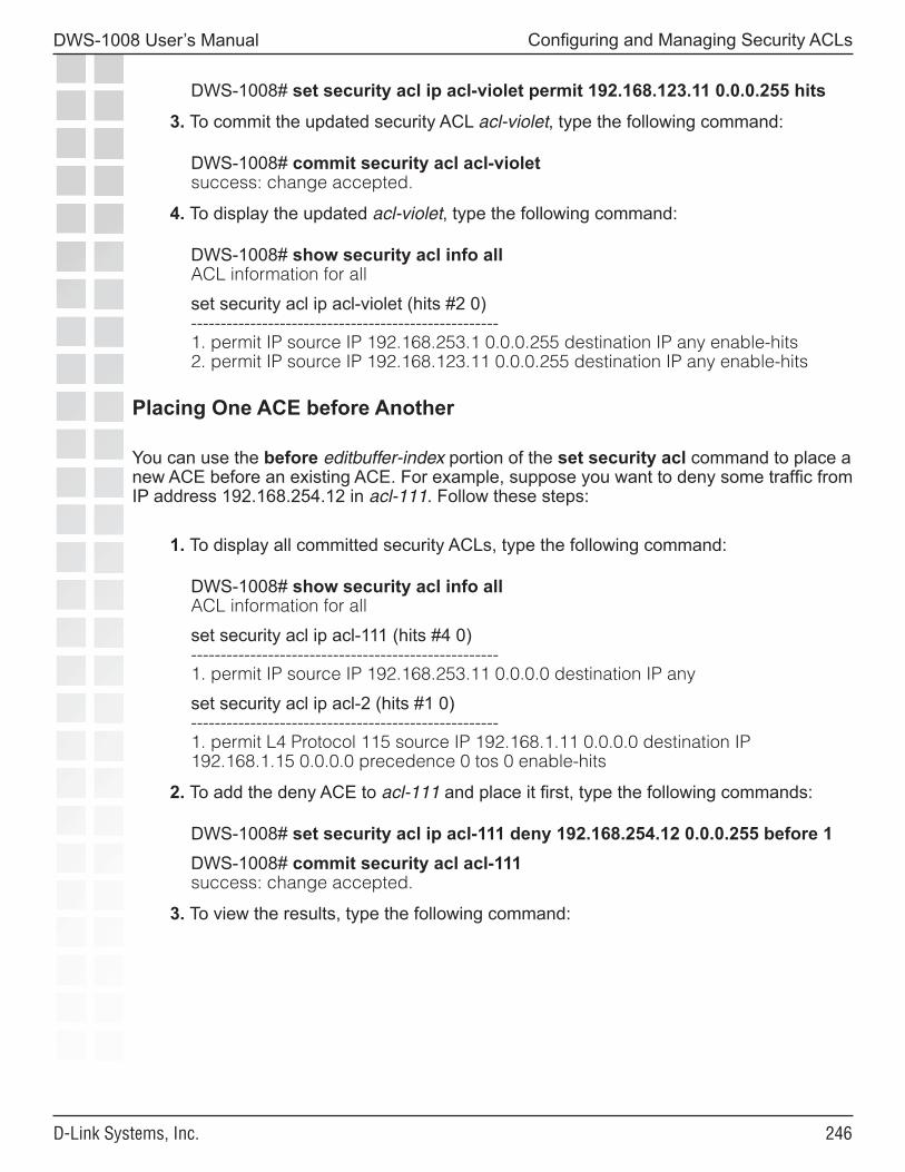
���
DWS-1008 User’s Manual
D-Link Systems, Inc.
Configuring and Managing Security ACLs
DWS-1008# set security acl ip acl-violet permit 192.168.123.11 0.0.0.255 hits
3. To commit the updated security ACL acl-violet, type the following command:
DWS-1008# commit security acl acl-violet success: change accepted.
4. To display the updated acl-violet, type the following command:
DWS-1008# show security acl info all ACL information for all
set security acl ip acl-violet (hits #2 0) ---------------------------------------------------- 1. permit IP source IP 192.168.253.1 0.0.0.255 destination IP any enable-hits 2. permit IP source IP 192.168.123.11 0.0.0.255 destination IP any enable-hits
Placing One ACE before Another
You can use the before editbuffer-index portion of the set security acl command to place a new ACE before an existing ACE. For example, suppose you want to deny some traffic from IP address 192.168.254.12 in acl-111. Follow these steps:
1. To display all committed security ACLs, type the following command:
DWS-1008# show security acl info all ACL information for all
set security acl ip acl-111 (hits #4 0) ---------------------------------------------------- 1. permit IP source IP 192.168.253.11 0.0.0.0 destination IP any
set security acl ip acl-2 (hits #1 0) ---------------------------------------------------- 1. permit L4 Protocol 115 source IP 192.168.1.11 0.0.0.0 destination IP
192.168.1.15 0.0.0.0 precedence 0 tos 0 enable-hits
2. To add the deny ACE to acl-111 and place it first, type the following commands:
DWS-1008# set security acl ip acl-111 deny 192.168.254.12 0.0.0.255 before 1 DWS-1008# commit security acl acl-111 success: change accepted.
3. To view the results, type the following command:
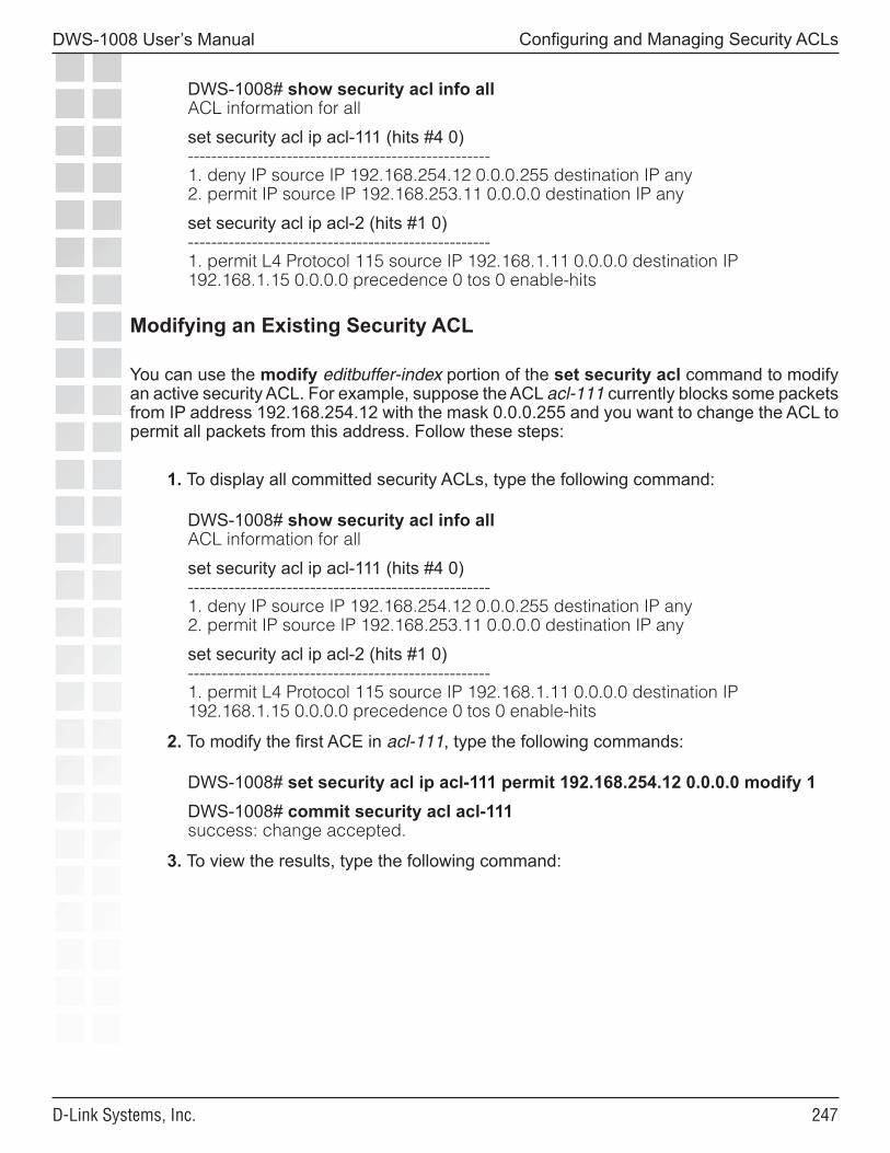
���
DWS-1008 User’s Manual
D-Link Systems, Inc.
Configuring and Managing Security ACLs
DWS-1008# show security acl info all ACL information for all
set security acl ip acl-111 (hits #4 0) ---------------------------------------------------- 1. deny IP source IP 192.168.254.12 0.0.0.255 destination IP any 2. permit IP source IP 192.168.253.11 0.0.0.0 destination IP any
set security acl ip acl-2 (hits #1 0) ---------------------------------------------------- 1. permit L4 Protocol 115 source IP 192.168.1.11 0.0.0.0 destination IP
192.168.1.15 0.0.0.0 precedence 0 tos 0 enable-hits
Modifying an Existing Security ACL
You can use the modify editbuffer-index portion of the set security acl command to modify an active security ACL. For example, suppose the ACL acl-111 currently blocks some packets from IP address 192.168.254.12 with the mask 0.0.0.255 and you want to change the ACL to permit all packets from this address. Follow these steps:
1. To display all committed security ACLs, type the following command:
DWS-1008# show security acl info all ACL information for all
set security acl ip acl-111 (hits #4 0) ---------------------------------------------------- 1. deny IP source IP 192.168.254.12 0.0.0.255 destination IP any 2. permit IP source IP 192.168.253.11 0.0.0.0 destination IP any
set security acl ip acl-2 (hits #1 0) ---------------------------------------------------- 1. permit L4 Protocol 115 source IP 192.168.1.11 0.0.0.0 destination IP
192.168.1.15 0.0.0.0 precedence 0 tos 0 enable-hits
2. To modify the first ACE in acl-111, type the following commands:
DWS-1008# set security acl ip acl-111 permit 192.168.254.12 0.0.0.0 modify 1 DWS-1008# commit security acl acl-111 success: change accepted.
3. To view the results, type the following command:
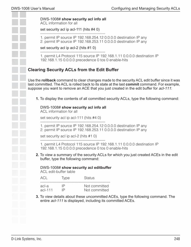
���
DWS-1008 User’s Manual
D-Link Systems, Inc.
Configuring and Managing Security ACLs
DWS-1008# show security acl info all ACL information for all
set security acl ip acl-111 (hits #4 0) ---------------------------------------------------- 1. permit IP source IP 192.168.254.12 0.0.0.0 destination IP any 2. permit IP source IP 192.168.253.11 0.0.0.0 destination IP any
set security acl ip acl-2 (hits #1 0) ---------------------------------------------------- 1. permit L4 Protocol 115 source IP 192.168.1.11 0.0.0.0 destination IP
192.168.1.15 0.0.0.0 precedence 0 tos 0 enable-hits
Clearing Security ACLs from the Edit Buffer
Use the rollback command to clear changes made to the security ACL edit buffer since it was last committed. The ACL is rolled back to its state at the last commit command. For example, suppose you want to remove an ACE that you just created in the edit buffer for acl-111:
1. To display the contents of all committed security ACLs, type the following command:
DWS-1008# show security acl info all ACL information for all
set security acl ip acl-111 (hits #4 0) ---------------------------------------------------- 1. permit IP source IP 192.168.254.12 0.0.0.0 destination IP any 2. permit IP source IP 192.168.253.11 0.0.0.0 destination IP any
set security acl ip acl-2 (hits #1 0) ---------------------------------------------------- 1. permit L4 Protocol 115 source IP 192.168.1.11 0.0.0.0 destination IP
192.168.1.15 0.0.0.0 precedence 0 tos 0 enable-hits
2. To view a summary of the security ACLs for which you just created ACEs in the edit buffer, type the following command:
DWS-1008# show security acl editbuffer ACL edit-buffer table
ACL Type Status -------------------------------------------------------- acl-a IP Not committed acl-111 IP Not committed
3. To view details about these uncommitted ACEs, type the following command. The entire acl-111 is displayed, including its committed ACEs.
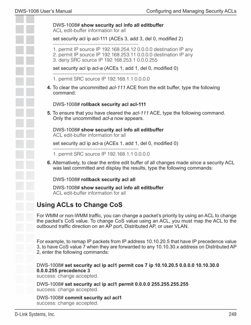
���
DWS-1008 User’s Manual
D-Link Systems, Inc.
Configuring and Managing Security ACLs
DWS-1008# show security acl info all editbuffer ACL edit-buffer information for all
set security acl ip acl-111 (ACEs 3, add 3, del 0, modified 2) ---------------------------------------------------- 1. permit IP source IP 192.168.254.12 0.0.0.0 destination IP any 2. permit IP source IP 192.168.253.11 0.0.0.0 destination IP any 3. deny SRC source IP 192.168.253.1 0.0.0.255
set security acl ip acl-a (ACEs 1, add 1, del 0, modified 0) ---------------------------------------------------- 1. permit SRC source IP 192.168.1.1 0.0.0.0
4. To clear the uncommitted acl-111 ACE from the edit buffer, type the following command:
DWS-1008# rollback security acl acl-111
5. To ensure that you have cleared the acl-111 ACE, type the following command. Only the uncommitted acl-a now appears.
DWS-1008# show security acl info all editbuffer ACL edit-buffer information for all
set security acl ip acl-a (ACEs 1, add 1, del 0, modified 0) ---------------------------------------------------- 1. permit SRC source IP 192.168.1.1 0.0.0.0
6. Alternatively, to clear the entire edit buffer of all changes made since a security ACL was last committed and display the results, type the following commands:
DWS-1008# rollback security acl all DWS-1008# show security acl info all editbuffer ACL edit-buffer information for all
Using ACLs to Change CoSFor WMM or non-WMM traffic, you can change a packet’s priority by using an ACL to change the packet’s CoS value. To change CoS value using an ACL, you must map the ACL to the outbound traffic direction on an AP port, Distributed AP, or user VLAN.
For example, to remap IP packets from IP address 10.10.20.5 that have IP precedence value 3, to have CoS value 7 when they are forwarded to any 10.10.30.x address on Distributed AP 2, enter the following commands:
DWS-1008# set security acl ip acl1 permit cos 7 ip 10.10.20.5 0.0.0.0 10.10.30.0 0.0.0.255 precedence 3success: change accepted.
DWS-1008# set security acl ip acl1 permit 0.0.0.0 255.255.255.255success: change accepted.
DWS-1008# commit security acl acl1success: change accepted.
��0
DWS-1008 User’s Manual
D-Link Systems, Inc.
Configuring and Managing Security ACLs
DWS-1008# set security acl map acl1 dap 2 outsuccess: change accepted.
The default action on an interface and traffic direction that has at least one access control entry (ACE) configured, is to deny all traffic that does not match an ACE on that interface and traffic direction. The permit 0.0.0.0 255.255.255.255 ACE ensures that traffic that does not match the first ACE is permitted. Without this additional ACE at the end, traffic that does not match the other ACE is dropped.
Filtering Based on DSCP Values
To filter based on a Differentiated Services Code Point (DSCP) value, specify the combination of precedence and ToS values that is equivalent to the DSCP value. For example, to filter based on DSCP value 46, configure an ACL that filters based on precedence 5 and ToS 12. (To display a table of the precedence and ToS combinations for each DSCP value, use the show security acl dscp command.)
The following commands remap IP packets from IP address 10.10.50.2 that have DSCP value 46 (equivalent to precedence value 5 and ToS value 12), to have CoS value 7 when they are forwarded to any 10.10.90.x address on Distributed AP 4:
DWS-1008# set security acl ip acl2 permit cos 7 ip 10.10.50.2 0.0.0.0 10.10.90.0 0.0.0.255 precedence 5 tos 12success: change accepted.
DWS-1008# set security acl ip acl2 permit cos 7 ip 10.10.50.2 0.0.0.0 10.10.90.0 0.0.0.255 precedence 5 tos 13success: change accepted.
DWS-1008# set security acl ip acl2 permit 0.0.0.0 255.255.255.255success: change accepted.
DWS-1008# commit security acl acl2success: change accepted.
DWS-1008# set security acl map acl2 dap 4 outsuccess: change accepted.
The ACL contains two ACEs. The first ACE matches on precedence 5 and ToS 12. The second ACE matches on precedence 5 and ToS 13. The IP precedence and ToS fields use 7 bits, while the DSCP field uses only 6 bits. Following the DSCP field is a 2-bit ECN field that can be set by other devices based on network congestion. The second ACE is required to ensure that the ACL matches regardless of the value of the seventh bit.
Class-of-Service (CoS) Packet Handling lists the CoS values to use when reassigning traffic to a different priority. The CoS determines the AP forwarding queue to use for the traffic when sending it to a wireless client.
Class-of-Service (CoS) Packet Handling
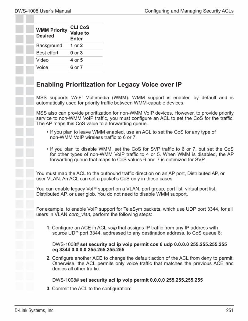
���
DWS-1008 User’s Manual
D-Link Systems, Inc.
Configuring and Managing Security ACLs
WMM Priority Desired
CLI CoS Value to Enter
Background 1 or 2Best effort 0 or 3Video 4 or 5 Voice 6 or 7
Enabling Prioritization for Legacy Voice over IP
MSS supports Wi-Fi Multimedia (WMM). WMM support is enabled by default and is automatically used for priority traffic between WMM-capable devices.
MSS also can provide prioritization for non-WMM VoIP devices. However, to provide priority service to non-WMM VoIP traffic, you must configure an ACL to set the CoS for the traffic. The AP maps this CoS value to a forwarding queue.
• If you plan to leave WMM enabled, use an ACL to set the CoS for any type of non-WMM VoIP wireless traffic to 6 or 7.
• If you plan to disable WMM, set the CoS for SVP traffic to 6 or 7, but set the CoS for other types of non-WMM VoIP traffic to 4 or 5. When WMM is disabled, the AP forwarding queue that maps to CoS values 6 and 7 is optimized for SVP.
You must map the ACL to the outbound traffic direction on an AP port, Distributed AP, or user VLAN. An ACL can set a packet’s CoS only in these cases.
You can enable legacy VoIP support on a VLAN, port group, port list, virtual port list, Distributed AP, or user glob. You do not need to disable WMM support.
For example, to enable VoIP support for TeleSym packets, which use UDP port 3344, for all users in VLAN corp_vlan, perform the following steps:
1. Configure an ACE in ACL voip that assigns IP traffic from any IP address with source UDP port 3344, addressed to any destination address, to CoS queue 6:
DWS-1008# set security acl ip voip permit cos 6 udp 0.0.0.0 255.255.255.255 eq 3344 0.0.0.0 255.255.255.255
2. Configure another ACE to change the default action of the ACL from deny to permit. Otherwise, the ACL permits only voice traffic that matches the previous ACE and denies all other traffic.
DWS-1008# set security acl ip voip permit 0.0.0.0 255.255.255.255
3. Commit the ACL to the configuration:
���
DWS-1008 User’s Manual
D-Link Systems, Inc.
Configuring and Managing Security ACLs
DWS-1008# commit security acl voip
4. Map the ACL to the outbound traffic direction of VLAN corp_vlan:
DWS-1008# set security acl map voip vlan corp_vlan out
Enabling SVP Optimization for SpectraLink Phones
You can configure MSS to prioritize voice traffic for VoIP phones that use SpectraLink Voice Priority (SVP). If you disable WMM support and enable SVP support, MSS ensures voice quality for SpectraLink phones using SVP by allocating CoS queues 6 and 7 on the MAP for distinct SVP treatment as well as forwarding all traffic from that queue before forwarding traffic from other queues.
You can enable SVP optimization on a VLAN, port group, port list, virtual port list, Distributed AP, or user glob. To enable SVP optimization, disable WMM support on the radio profile that serves the SVP users, configure an ACL that assigns traffic for IP protocol 119 to CoS queue 6 or 7, and map the ACL to the outbound traffic direction.
For example, to enable SVP support for all users in VLAN corp_vlan, perform the following steps:
1. Disable WMM support on the radio profile that will serve SVP users, to enable SVP optimization on AP forwarding queues 6 and 7 for radios managed by that radio profile:
DWS-1008# set radio-profile radprofsvp wmm disable
2. Configure an ACE in ACL svp that assigns IP protocol 119 traffic for all source and destination addresses to CoS queue 7:
DWS-1008# set security acl ip svp permit cos 7 119 0.0.0.0 255.255.255.255 0.0.0.0 255.255.255.255
3. Configure another ACE to change the default action of the ACL from deny to permit. Otherwise, the ACL permits only voice traffic that matches the previous ACE and denies all other traffic.
DWS-1008# set security acl ip svp permit 0.0.0.0 255.255.255.255
4. Commit the ACL to the configuration:
DWS-1008# commit security acl svp
5. Map the ACL to the outbound traffic direction of VLAN corp_vlan:
DWS-1008# set security acl map voip vlan corp_vlan out
���
DWS-1008 User’s Manual
D-Link Systems, Inc.
Configuring and Managing Security ACLs
Security ACL Configuration Scenario
The following scenario illustrates how to create a security ACL named acl-99 that consists of one ACE to permit incoming packets from one IP address, and how to map the ACL to a port and a user:
1. Type the following command to create and name a security ACL and add an ACE to it.
DWS-1008# set security acl ip acl-99 permit 192.168.1.1 0.0.0.0
2. To view the ACE you have entered, type the following command:
DWS-1008# show security acl editbuffer ACL Type Status ----------------------------------------------- acl-99 IP Not committed
3. To save acl-99 and its associated ACE to the configuration, type the following command:
DWS-1008# commit security acl acl-99 success: change accepted.
4. To map acl-99 to port 9 to filter incoming packets, type the following command:
DWS-1008# set security acl map acl-99 port 9 in mapping configuration accepted
Because every security ACL includes an implicit rule denying all traffic that is not permitted, port 9 now accepts packets only from 192.168.1.1, and denies all other packets.
5. To map acl-99 to user Natasha’s sessions when you are using the local DWS-1008 switch database for authentication, configure Natasha in the database with the Filter-Id attribute. Type the following commands:
DWS-1008# set authentication dot1x Natasha local success: change accepted.
DWS-1008# set user natasha attr filter-id acl-99.in success: change accepted.
6. Alternatively, you can map acl-99 to Natasha’s sessions when you are using a remote RADIUS server for authentication. To configure Natasha for pass-through authentication to the RADIUS server shorebirds, type the following command:
DWS-1008# set authentication dot1x Natasha pass-through shorebirds success: change accepted.
You must then map the security ACL to Natasha’s session in RADIUS. For instructions, see the documentation for your RADIUS server.
���
DWS-1008 User’s Manual
D-Link Systems, Inc.
Configuring and Managing Security ACLs
7. To save your configuration, type the following command:
DWS-1008# save config success: configuration saved.
���
DWS-1008 User’s Manual
D-Link Systems, Inc.
Managing Keys and Certificates
A digital certificate is a form of electronic identification for computers. The DWS-1008 switch requires digital certificates to authenticate its communications to Extensible Authentication Protocol (EAP) clients for which the switch performs all EAP processing. Certificates can be generated on the switch or obtained from a certificate authority (CA). Keys contained within the certificates allow the switch, its servers, and its wireless clients to exchange information secured by encryption.
Note: Before installing a certificate, verify with the show timedate and show timezone commands that the switch is set to the correct date, time, and time zone. Otherwise, certificates might not be installed correctly.
Why Use Keys and Certificates?
Certain switch operations require the use of public-private key pairs and digital certificates. All users for which the switch performs IEEE 802.1X EAP authentication require public-private key pairs and digital certificates to be installed on the switch.
These keys and certificates are fundamental to securing wireless, wired authentication, and administrative connections because they support Wi-Fi Protected Access (WPA) encryption and dynamic Wired-Equivalency Privacy (WEP) encryption.
Wireless Security through TLS
In the case of wireless or wired authentication 802.1X users whose authentication is performed by the switch, the first stage of any EAP transaction is Transport Layer Security (TLS) authentication and encryption.
TLS allows the client to authenticate the switch (and optionally allows the switch to authenticate the client) through the use of digital signatures. Digital signatures require a public-private key pair. The signature is created with a private key and verified with a public key. TLS enables secure key exchange.
PEAP-MS-CHAP-V2 Security
PEAP performs a TLS exchange for server authentication and allows a secondary authentication to be performed inside the resulting secure channel for client authentication.
For example, the Microsoft Challenge Handshake Authentication Protocol version 2 (MS-CHAP-V2) performs mutual MS-CHAP-V2 authentication inside an encrypted TLS channel established by PEAP.
1. To form the encrypted TLS channel, the switch must have a digital certificate and must send that certificate to the wireless client.
Managing Keys and Certificates
���
DWS-1008 User’s Manual
D-Link Systems, Inc.
Managing Keys and Certificates
2. Inside the switch’s digital certificate is the switch’s public key, which the wireless client uses to encrypt a pre-master secret key.
3. The wireless client then sends the key back to the switch so that both the switch and the client can derive a key from this pre-master secret for secure authentication and wireless session encryption.
Clients authenticated by PEAP need a certificate in the switch only when the switch performs PEAP locally, not when EAP processing takes place on a RADIUS server.
About Keys and Certificates
Public-private key pairs and digital signatures and certificates allow keys to be generated dynamically so that data can be securely encrypted and delivered. You generate the key pairs and certificates on the switch or install them on the switch after enrolling with a certificate authority (CA). The switch can generate key pairs, self-signed certificates, and Certificate Signing Requests (CSRs), and can install key pairs, server certificates, and certificates generated by a CA.
When the switch needs to communicate with an 802.1X client, MSS requests a private key from the switch’s certificate and key store:
• If no private key is available in the switch’s certificate and key store, the switch does not respond to the request from MSS. If the switch does have a private key in its key store, MSS requests a corresponding certificate.
• If the switch has a self-signed certificate in its certificate and key store, the switch responds to the request from MSS. If the certificate is not self-signed, the switch looks for a CA’s certificate with which to validate the server certificate.
• If the switch has no corresponding CA certificate, the switch does not respond to the request from MSS. If the switch does have a corresponding CA certificate, and the server certificate is validated (date still valid, signature approved), the switch responds.
If the switch does not respond to the request from MSS, authentication fails and access is denied.
For EAP (802.1X) users, the public-private key pairs and digital certificates can be stored on a RADIUS server. In this case, the switch operates as a pass-through authenticator.
���
DWS-1008 User’s Manual
D-Link Systems, Inc.
Managing Keys and Certificates
Public Key Infrastructures
A public-key infrastructure (PKI) is a system of digital certificates and certification authorities that verify and authenticate the validity of each party involved in a transaction through the use of public key cryptography. To have a PKI, the switch requires the following:
• A public key• A private key• Digital certificates• A CA• A secure place to store the private key
A PKI enables you to securely exchange and validate digital certificates between switches, servers, and users so that each device can authenticate itself to the others.
Public and Private Keys
D-Link’s identity-based networking uses public key cryptography to enforce the privacy of data transmitted over the network. Using public-private key pairs, users and devices can send encrypted messages that only the intended receiver can decrypt.
Before exchanging messages, each party in a transaction creates a key pair that includes the public and private keys. The public key encrypts data and verifies digital signatures, and the corresponding private key decrypts data and generates digital signatures. Public keys are freely exchanged as part of digital certificates. Private keys are stored securely.
Digital Certificates
Digital certificates bind the identity of network users and devices to a public key. Network users must authenticate their identity to those with whom they communicate, and must be able to verify the identity of other users and network devices, such as switches and RADIUS servers.
The D-Link MobileLAN system supports the following types of X.509 digital certificates:
• EAP certificate - Used by the switch to authenticate itself to EAP clients.
• Certificate authority (CA) certificates - Used by the switch in addition to the certificates listed above, when those certificates are from the CA.
The Admin and EAP certificates can be generated by the switch (self-signed) or generated and signed by a CA. If they are signed by a CA, the CA’s own certificate is also required.
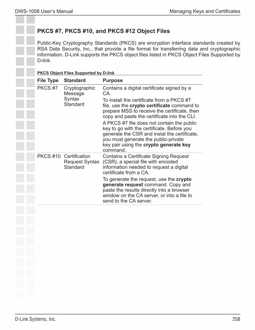
���
DWS-1008 User’s Manual
D-Link Systems, Inc.
Managing Keys and Certificates
PKCS #7, PKCS #10, and PKCS #12 Object Files
Public-Key Cryptography Standards (PKCS) are encryption interface standards created by RSA Data Security, Inc., that provide a file format for transferring data and cryptographic information. D-Link supports the PKCS object files listed in PKCS Object Files Supported by D-link.
PKCS Object Files Supported by D-link
File Type Standard PurposePKCS #7 Cryptographic
Message Syntax Standard
Contains a digital certificate signed by a CA. To install the certificate from a PKCS #7 file, use the crypto certificate command to prepare MSS to receive the certificate, then copy and paste the certificate into the CLI.A PKCS #7 file does not contain the public key to go with the certificate. Before you generate the CSR and instal the certificate, you must generate the public-private key pair using the crypto generate key command.
PKCS #10 Certification Request Syntax Standard
Contains a Certificate Signing Request (CSR), a special file with encoded information needed to request a digital certificate from a CA. To generate the request, use the crypto generate request command. Copy and paste the results directly into a browser window on the CA server, or into a file to send to the CA server.
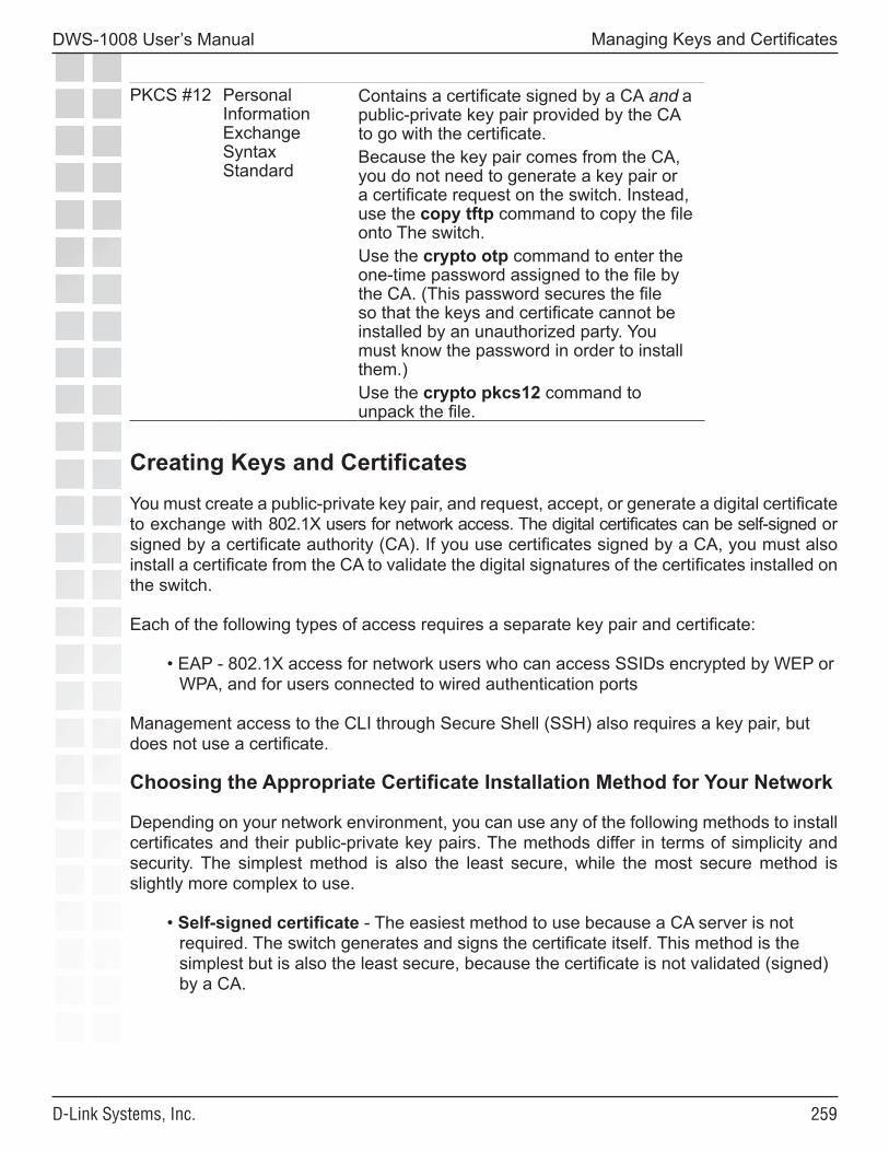
���
DWS-1008 User’s Manual
D-Link Systems, Inc.
Managing Keys and Certificates
PKCS #12 Personal Information Exchange Syntax Standard
Contains a certificate signed by a CA and a public-private key pair provided by the CA to go with the certificate. Because the key pair comes from the CA, you do not need to generate a key pair or a certificate request on the switch. Instead, use the copy tftp command to copy the file onto The switch. Use the crypto otp command to enter the one-time password assigned to the file by the CA. (This password secures the file so that the keys and certificate cannot be installed by an unauthorized party. You must know the password in order to install them.) Use the crypto pkcs12 command to unpack the file.
Creating Keys and CertificatesYou must create a public-private key pair, and request, accept, or generate a digital certificate to exchange with 802.1X users for network access. The digital certificates can be self-signed or signed by a certificate authority (CA). If you use certificates signed by a CA, you must also install a certificate from the CA to validate the digital signatures of the certificates installed on the switch. Each of the following types of access requires a separate key pair and certificate:
• EAP - 802.1X access for network users who can access SSIDs encrypted by WEP or WPA, and for users connected to wired authentication ports
Management access to the CLI through Secure Shell (SSH) also requires a key pair, but does not use a certificate.
Choosing the Appropriate Certificate Installation Method for Your Network
Depending on your network environment, you can use any of the following methods to install certificates and their public-private key pairs. The methods differ in terms of simplicity and security. The simplest method is also the least secure, while the most secure method is slightly more complex to use.
• Self-signed certificate - The easiest method to use because a CA server is not required. The switch generates and signs the certificate itself. This method is the simplest but is also the least secure, because the certificate is not validated (signed) by a CA.
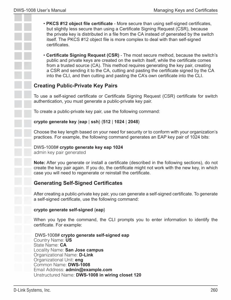
��0
DWS-1008 User’s Manual
D-Link Systems, Inc.
Managing Keys and Certificates
• PKCS #12 object file certificate - More secure than using self-signed certificates, but slightly less secure than using a Certificate Signing Request (CSR), because the private key is distributed in a file from the CA instead of generated by the switch itself. The PKCS #12 object file is more complex to deal with than self-signed certificates.
• Certificate Signing Request (CSR) - The most secure method, because the switch’s public and private keys are created on the switch itself, while the certificate comes from a trusted source (CA). This method requires generating the key pair, creating a CSR and sending it to the CA, cutting and pasting the certificate signed by the CA into the CLI, and then cutting and pasting the CA’s own certificate into the CLI.
Creating Public-Private Key Pairs
To use a self-signed certificate or Certificate Signing Request (CSR) certificate for switch authentication, you must generate a public-private key pair.
To create a public-private key pair, use the following command:
crypto generate key {eap | ssh} {512 | 1024 | 2048}
Choose the key length based on your need for security or to conform with your organization’s practices. For example, the following command generates an EAP key pair of 1024 bits:
DWS-1008# crypto generate key eap 1024admin key pair generated
Note: After you generate or install a certificate (described in the following sections), do not create the key pair again. If you do, the certificate might not work with the new key, in which case you will need to regenerate or reinstall the certificate.
Generating Self-Signed Certificates
After creating a public-private key pair, you can generate a self-signed certificate. To generate a self-signed certificate, use the following command:
crypto generate self-signed {eap}
When you type the command, the CLI prompts you to enter information to identify the certificate. For example:
DWS-1008# crypto generate self-signed eapCountry Name: USState Name: CALocality Name: San Jose campusOrganizational Name: D-LinkOrganizational Unit: engCommon Name: DWS-1008Email Address: [email protected] Name: DWS-1008 in wiring closet 120
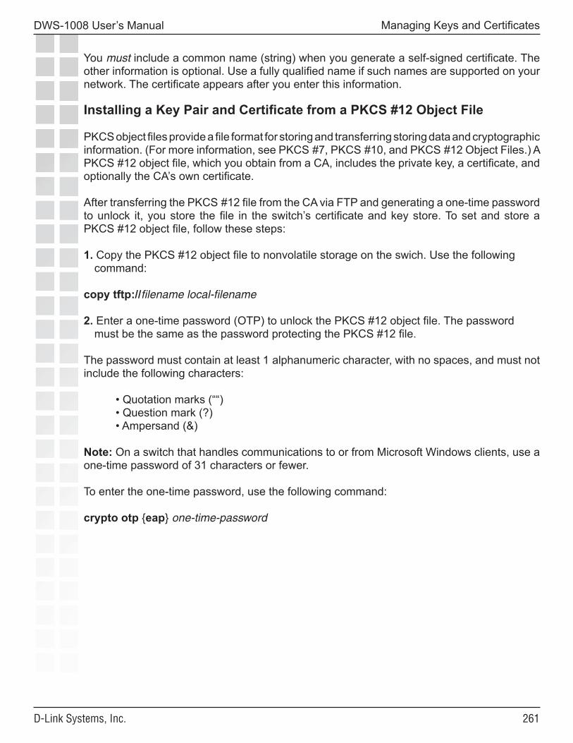
���
DWS-1008 User’s Manual
D-Link Systems, Inc.
Managing Keys and Certificates
You must include a common name (string) when you generate a self-signed certificate. The other information is optional. Use a fully qualified name if such names are supported on your network. The certificate appears after you enter this information.
Installing a Key Pair and Certificate from a PKCS #12 Object File
PKCS object files provide a file format for storing and transferring storing data and cryptographic information. (For more information, see PKCS #7, PKCS #10, and PKCS #12 Object Files.) A PKCS #12 object file, which you obtain from a CA, includes the private key, a certificate, and optionally the CA’s own certificate.
After transferring the PKCS #12 file from the CA via FTP and generating a one-time password to unlock it, you store the file in the switch’s certificate and key store. To set and store a PKCS #12 object file, follow these steps:
1. Copy the PKCS #12 object file to nonvolatile storage on the swich. Use the following command:
copy tftp://filename local-filename
2. Enter a one-time password (OTP) to unlock the PKCS #12 object file. The password must be the same as the password protecting the PKCS #12 file.
The password must contain at least 1 alphanumeric character, with no spaces, and must not include the following characters:
• Quotation marks (““)• Question mark (?)• Ampersand (&)
Note: On a switch that handles communications to or from Microsoft Windows clients, use a one-time password of 31 characters or fewer.
To enter the one-time password, use the following command:
crypto otp {eap} one-time-password
���
DWS-1008 User’s Manual
D-Link Systems, Inc.
Managing Keys and Certificates
3. Unpack the PKCS #12 object file into the certificate and key storage area on the switch. Use the following command:
crypto pkcs12 {eap} filename
The filename is the location of the file on the switch.
Creating a CSR and Installing a Certificate from a PKCS #7 Object File
After creating a public-private key pair, you can obtain a signed certificate of authenticity from a CA by generating a Certificate Signing Request (CSR) from the switch. A CSR is a text block with an encoded request for a signed certificate from the CA.
Note: Many certificate authorities have their own unique requirements. Follow the instructions in the documentation for your CA to properly format the fields you complete when generating a CSR.
1. To generate a request for a CA-signed certificate, use the following command:
crypto generate request {eap}
When prompted, enter values for each of six identification fields.
You must include a common name (string) when you generate a CSR. Use a fully qualified name if such names are supported on your network. The other information is optional. For example:
DWS-1008#dws-1008# crypto generate request adminCountry Name: USState Name: MILocality Name: DetroitOrganizational Name: exampleOrganizational Unit: engCommon Name: DWS-1008Email Address: [email protected] Name: south tower, wiring closet 125
When completed successfully, the command returns a Privacy-Enhanced Mail (PEM) formatted PKCS #10 CSR. PEM encoding is a way of representing a non-ASCII file format in ASCII characters. The encoded object is the PKCS #10 CSR. Give the CSR to a CA and receive a signed certificate (a PEM-encoded PKCS #7 object file). 2. To install a certificate from a PKCS #7 file, use the following command to prepare the
switch to receive it:
crypto certificate {eap} PEM-formatted certificate
3. Use a text editor to open the PKCS #7 file, and copy and paste the entire text block, including the beginning and ending delimiters, into the CLI.
Note: You must paste the entire block, from the beginning -----BEGIN CERTIFICATE REQUEST----- to the end -----END CERTIFICATE REQUEST-----.
���
DWS-1008 User’s Manual
D-Link Systems, Inc.
Managing Keys and Certificates
Installing a CA’s Own Certificate
If you installed a CA-signed certificate from a PKCS #7 file, you must also install the PKCS #7 certificate of that CA. (If you used the PKCS #12 method, the CA’s certificate is usually included with the key pair and server certificate.)
To install a CA’s certificate, use the following command:
crypto ca-certificate {eap} PEM-formatted-certificate
When prompted, paste the certificate under the prompt. For example:
DWS-1008# crypto ca-certificate eapEnter PEM-encoded certificate-----BEGIN CERTIFICATE-----MIIDwDCCA2qgAwIBAgIQL2jvuu4PO5FAQCyewU3ojANBgkqhkiG9wOBAQUFADCBmzerMClaweVQQTTooewi\wpoer0QWNFNkj90044mbdrl1277SWQ8G7DiwYUtrqoQplKJ.....Lm8wmVYxP56M;CUAm908C2foYgOY40=-----END CERTIFICATE-----
Displaying Certificate and Key Information
To display information about certificates installed on an switch, use the following commands:
show crypto ca-certificate {eap}show crypto certificate {eap}
For example, to display information about an administrative certificate, type the following command:
DWS-1008# show crypto certificate eapCertificate: Version: 3 Serial Number: 999 (0x3e7) Subject: C=US, ST=CA, L=PLEAS, O=TRPZ, OU=SQA, CN=BOBADMIN/emailAddress=BOBADMIN, unstructuredName=BOB Signature Algorithm: md5WithRSAEncryption Issuer: C=US, ST=CA, L=PLEAS, O=TRPZ, OU=SQA, CN=BOBADMIN/emailAddress=BOBADMIN, unstructuredName=BOB Validity: Not Before: Oct 19 01:57:13 2004 GMT Not After : Oct 19 01:57:13 2005 GMT
The last two rows of the display indicate the period for which the certificate is valid. Make sure the date and time set on the switch are within the date and time range of the certificate.
���
DWS-1008 User’s Manual
D-Link Systems, Inc.
Managing Keys and Certificates
Key and Certificate Configuration ScenariosThe first scenario shows how to generate self-signed certificates. The second scenario shows how to install CA-signed certificates using PKCS #12 object files, and the third scenario shows how to install CA-signed certificates using CSRs (PKCS #10 object files) and PKCS #7 object files.
Creating Self-Signed Certificates
To manage the security of communication with 802.1X users, create EAP public-private key pairs and self-signed certificates. Follow these steps:
1. Set time and date parameters, if not already set.
2. Generate public-private key pairs:
DWS-1008# crypto generate key eap 1024key pair generated
3. Generate self-signed certificates:
DWS-1008# crypto generate self-signed eapCountry Name: USState Name: CALocality Name: San FranciscoOrganizational Name: exampleOrganizational Unit: ITCommon Name: DWS-1008Email Address: [email protected] Name: DWS-1008 in wiring closet 4Self-signed cert for eap is
-----BEGIN CERTIFICATE-----MIICUzCCAbygAwIBAgICA+cwDQYJKoZIhvcNAQEEBQAwNjELMAkGA1UEBhMCVVMxCzAJBgNVBAgTAkNBMRowGAYDVQQDFBF0ZWNocHVic0B0cnB6LmNvbTAeFw0wMzA0...Lm8wmVYLxP56MMX-
���
DWS-1008 User’s Manual
D-Link Systems, Inc.
Managing Keys and Certificates
4. Display certificate information for verification:
DWS-1008# show crypto certificate eapCertificate: Version: 3 Serial Number: 999 (0x3e7) Subject: C=US, ST=CA, L=PLEAS, O=TRPZ, OU=SQA, CN=BOBADMIN/emailAddress=BOBADMIN, unstructuredName=BOB Signature Algorithm: md5WithRSAEncryption Issuer: C=US, ST=CA, L=PLEAS, O=TRPZ, OU=SQA, CN=BOBADMIN/emailAddress=BOBADMIN, unstructuredName=BOB Validity: Not Before: Oct 19 01:59:42 2004 GMT Not After : Oct 19 01:59:42 2005 GMT
���
DWS-1008 User’s Manual
D-Link Systems, Inc.
Managing Keys and Certificates
Installing CA-Signed Certificates from PKCS #12 Object Files
This scenario shows how to use PKCS #12 object files to install public-private key pairs, CA-signed certificates, and CA certifies for 802.1X (EAP) access.
1. Set time and date parameters, if not already set.
2. Obtain PKCS #12 object files from a certificate authority.
3. Copy the PKCS #12 object files to nonvolatile storage on the switch. Use the following command:
copy tftp://filename local-filename
For example, to copy 20481x.p12 from the TFTP server at the address 192.168.253.1, type the following commands:
DWS-1008# copy tftp://192.168.253.1/20481x.p12 20481x.p12success: received 637 bytes in 0.253 seconds [ 2517 bytes/sec]
4. Enter the one-time passwords (OTPs) for the PKCS #12 object files. The OTP protects the PKCS #12 file.
To enter a one-time password, use the following command:
crypto otp {admin | eap} one-time-password
For example:
DWS-1008# crypto otp eap SeC%#6@o%dOTP set
5. Unpack the PKCS #12 object files into the certificate and key storage area on The switch. Use the following command:
crypto pkcs12 {eap} filenameThe filename is the location of the file on the switch.
For example:
DWS-1008# crypto pkcs12 eap 20481x.p12Unwrapped from PKCS12 file: keypair device certificate CA certificate
Note: MSS erases the OTP password entered with the crypto otp command when you enter the crypto pkcs12 command.
���
DWS-1008 User’s Manual
D-Link Systems, Inc.
Managing Keys and Certificates
Installing CA-Signed Certificates Using a PKCS #10 Object File (CSR) and a PKCS #7 Object File
This scenario shows how to use CSRs to install public-private key pairs, CA-signed certificates, and CA certifies for 802.1X (EAP) access.
1. Set time and date parameters, if not already set.
2. Generate public-private key pairs:
DWS-1008# crypto generate key eap 1024key pair generated
3. Create a CSR (PKCS #10 object file) to request an administrative certificate:
DWS-1008# crypto generate request eapCountry Name: USState Name: CALocality Name: CambriaOrganizational Name: exampleOrganizational Unit: engCommon Name: DWS-1008Email Address: [email protected] Name: wiring closet 12CSR for eap is-----BEGIN CERTIFICATE REQUEST-----IIBdTCB3wIBADA2MQswCQYDVQQGEwJVUzELMAkGA1UECBMCQ0ExGjAYBgNVBAMUEXRlY2hwdWJzQHRycHouY29tMIGfMA0GCSqGSIb3DQEBAQUAA4GNADCBiQKBgQC4...2L8Q9tk+G2As84QYMwe9RJAjfbYM5bdWRUFiLzvK7BJgqBsCZz4DP00=-----END CERTIFICATE REQUEST-----
4. Copy the CSR into the CA’s application.
Note: You must paste the entire block, from the beginning -----BEGIN CERTIFICATE REQUEST----- to the end -----END CERTIFICATE REQUEST-----. 5. Transfer the signed eap certificate (PKCS #7 object file) from the CA to your computer.
6. Open the signed certificate file with a text editor. Copy the entire file from the first hyphen to the last.
7. To install the administrative certificate on the switch, type the following command to display a prompt:
DWS-1008# crypto certificate eapEnter PEM-encoded certificate
���
DWS-1008 User’s Manual
D-Link Systems, Inc.
Managing Keys and Certificates
8. Paste the signed certificate text block into the switch’s CLI, below the prompt.
9. Display information about the certificate, to verify it:
DWS-1008# show crypto certificate eap
10. Repeat Create a CSR (PKCS #10 object file) to request an ad through Display information about the certificate, to verify it: to obtain and install EAP (802.1X) certificate.
11. Obtain the CA’s own certificate.
12. To install the CA’s certificate on the switch and help authenticate the switch’s EAP certificate, type the following command to display a prompt:
DWS-1008# crypto ca-certificate eap Enter PEM-encoded certificate
13. Paste the CA’s signed certificate under the prompt.
14. Display information about the CA’s certificate, to verify it:
DWS-1008# show crypto ca-certificate eap
15. Repeat To install the CA’s certificate on the switch through Display information about the CA’s certificate, to verify it: to install the CA’s certificate for EAP (802.1X).
���
DWS-1008 User’s Manual
D-Link Systems, Inc.
Managing Keys and Certificates
Notes
��0
DWS-1008 User’s Manual
D-Link Systems, Inc.
Configuring AAA for Network Users
Configuring AAA for Network Users
About AAA for Network Users
Network users include the following types of users:
• Wireless users - Users who access the network by associating with an SSID on a D-Link radio.
• Wired authentication users - Users who access the network over an Ethernet connection to a switch port that is configured as a wired authentication (wired-auth) port.
You can configure authentication rules for each type of user, on an individual SSID or wired authentication port basis. MSS authenticates users based on user information on RADIUS servers or in the switch’s local database. The RADIUS servers or local database authorize successfully authenticated users for specific network access, including VLAN membership. Optionally, you also can configure accounting rules to track network access information.
The following sections describe the MSS authentication, authorization, and accounting (AAA) features in more detail.
Authentication
When a user attempts to access the network, MSS checks for an authentication rule that matches the following parameters:
• For wireless access, the authentication rule must match the SSID the user is requesting, and the user’s username or MAC address.
• For access on a wired authentication port, the authentication rule must match the user’s username or MAC address.
If a matching rule is found, MSS then checks RADIUS servers or the switch’s local user database for credentials that match those presented by the user. Depending on the type of authentication rule that matches the SSID or wired authentication port, the required credentials are the username or MAC address, and in some cases, a password.
Each authentication rule specifies where the user credentials are stored. The location can be a group of RADIUS servers or the switch’s local database. In either case, if MSS has an authentication rule that matches on the required parameters, MSS checks the username or MAC address of the user and, if required, the password to make sure they match the information configured on the RADIUS servers or in the local database.
���
DWS-1008 User’s Manual
D-Link Systems, Inc.
Configuring AAA for Network Users
The username or MAC address can be an exact match or can match a userglob or MAC address glob, which allow wildcards to be used for all or part of the username or MAC address.
Authentication Types
MSS provides the following types of authentication:
• IEEE 802.1X - If the network user’s network interface card (NIC) supports 802.1X, MSS checks for an 802.1X authentication rule that matches the username (and SSID, if wireless access is requested), and that uses the Extensible Authentication Protocol (EAP) requested by the NIC. If a matching rule is found, MSS uses the requested EAP to check the RADIUS server group or local database for the username and password entered by the user. If matching information is found, MSS grants access to the user.
• MAC - If the username does not match an 802.1X authentication rule, but the MAC address of the user’s NIC or Voice-over-IP (VoIP) phone and the SSID (if wireless) do match a MAC authentication rule, MSS checks the RADIUS server group or local database for matching user information. If the MAC address (and password, if on a RADIUS server) matches, MSS grants access. Otherwise, MSS attempts the fallthru authentication type, which can be last-resort or none. (Fallthru authentication is described in more detail in Authentication Algorithm.)
• Last-resort - A network user requests access to the network, without entering a username or password. MSS checks for a last-resort authentication rule for the requested SSID (or for wired, if the user is on a wired authentication port). If a matching rule is found, MSS checks the RADIUS server group or local database for username last-resort-wired (for wired authentication access) or last-resort-ssid, where ssid is the SSID requested by the user. If the user information is on a RADIUS server, MSS also checks for a password.
Authentication Algorithm
MSS can try more than one of the authentication types described in Authentication Types to authenticate a user. MSS tries 802.1X first. If the user’s NIC supports 802.1X but fails authentication, MSS denies access. Otherwise, MSS tries MAC authentication next. If MAC authentication is successful, MSS grants access to the user. Otherwise, MSS tries the fallthru authentication type specified for the SSID or wired authentication port. The fallthru authentication type can be one of the following:
• Last-resort• None
���
DWS-1008 User’s Manual
D-Link Systems, Inc.
Configuring AAA for Network Users
Last-resort is described in Authentication Types. None means the user is automatically denied access. The fallthru authentication type for wireless access is associated with the SSID (through a service profile). The fallthru authentication type for wired authentication access is specified with the wired authentication port.
Note: The fallthru authentication type None is different from the authentication method none you can specify for administrative access. The fallthru authentication type None denies access to a network user. In contrast, the authentication method none allows access to the switch by an administrator.
SSID Name “Any”
In authentication rules for wireless access, you can specify the name any for the SSID. This value is a wildcard that matches on any SSID string requested by the user.
For 802.1X rules that match on SSID any, MSS checks the RADIUS servers or local database for the username (and password, if applicable) entered by the user. If the user information matches, MSS grants access to the SSID requested by the user, regardless of which SSID name it is.
For MAC authentication rules that match on SSID any, MSS checks the RADIUS servers or local database for the MAC address (and password, if applicable) of the user’s device. If the address matches, MSS grants access to the SSID requested by the user, regardless of which SSID name it is.
However, in a last-resort authentication rule for wireless access, if the SSID name in the authentication rule is any, MSS checks the RADIUS servers or local database for username last-resort-any, exactly as spelled here. If checking RADIUS, MSS also checks for a password. Access is granted only if this username (and password, if applicable) is found. Otherwise, access is denied.
Last-Resort Processing
When a user without a username or password requests wireless access, MSS checks the configuration for a last-resort authentication rule that matches on the SSID. If the configuration contains the rule, MSS checks the local database for username last-resort-ssid, where ssid is the SSID requested by the user. The guest user is granted access only if the database or RADIUS server group contains last-resort-ssid for the SSID requested by the user. Otherwise, access is denied.
This processing of the last-resort username is different from 802.1X or MAC, where MSS checks for the exact username or MAC address (and password, if applicable) of the user. MSS does not append the SSID to the username (or MAC address) for 802.1X or MAC authentication.
User Credential Requirements
The user credentials that MSS checks for on RADIUS servers or in the local database differ depending on the type of authentication rule that matches on the SSID or wired access requested by the user.
���
DWS-1008 User’s Manual
D-Link Systems, Inc.
Configuring AAA for Network Users
• For a user to be successfully authenticated by an 802.1X rule, the username and password entered by the user must be configured on the RADIUS servers used by the authentication rule or in the switch’s local database, if the local database is used by the rule.
• For a user to be successfully authenticated based on the MAC address of the user’s device, the MAC address must be configured on the RADIUS servers used by the authentication rule or in the switch’s local database, if the local database is used by the rule. If the MAC address is configured in the local database, no password is required. However, since RADIUS requires a password, if the MAC address is on the RADIUS server, MSS checks for a password. The default well-known password is dlink but it is configurable. (The same password applies to last-resort users.)
• For a user to be successfully authenticated for last-resort access, the RADIUS severs or local database (whichever method is used by the last-resort authentication rule), must contain a user named last-resort-wired (for wired authentication access) or last-resort-ssid, where ssid is the SSID requested by the user. If the matching last-resort user is configured in the local database, no password is required. However, since RADIUS requires a password, if the matching last-resort user is on the RADIUS server, MSS checks for a password. The default well-known password is dlink but is configurable. (The same password applies to MAC users.)
If the last-resort authentication rule matches on SSID any, which is a wildcard that matches on any SSID string, the RADIUS servers or local database must have user last-resort-any, exactly as spelled here.
Authorization
If the user is authenticated, MSS then checks the RADIUS server or local database (the same place MSS looked for user information to authenticate the user) for the authorization attributes assigned to the user. Authorization attributes specify the network resources the user can access.
The only required attribute is the Virtual LAN (VLAN) name on which to place the user. RADIUS and MSS have additional optional attributes. For example, you can provide further access controls by specifying the times during which the user can access the network, you can apply inbound and outbound access control lists (ACLs) to the user’s traffic, and so on. To assign attributes on the RADIUS server, use the standard RADIUS attributes supported on the server. To assign attributes in the switch’s local database, use the MSS vendor-specific attributes (VSAs).
MSS provides the following VSAs, which you can assign to users configured in the local database or on a RADIUS server:
• Encryption-Type - Specifies the type of encryption required for access by the client. Clients who attempt to use an unauthorized encryption method are rejected.
• End-Date - Date and time after which the user is no longer allowed to be on the network.
���
DWS-1008 User’s Manual
D-Link Systems, Inc.
Configuring AAA for Network Users
• Mobility-Profile - Controls the switch ports a user can access. For wireless users, an MSS Mobility Profile specifies the access points through which the user can access the network. For wired authentication users, the Mobility Profile specifies the wired authentication ports through which the user can access the network.
• SSID - SSID the user is allowed to access after authentication.
• Start-Date - Date and time at which the user becomes eligible to access the network. MSS does not authenticate the user unless the attempt to access the network occurs at or after the specified date and time, but before the end-date (if specified).
• Time-of-Day - Day(s) and time(s) during which the user is permitted to log into the network.
• VLAN-Name - VLAN to place the user on.
You also can assign the following RADIUS attributes to users configured in the local database.
• Filter-Id - Security ACL that permits or denies traffic received (input) or sent (output) the switch.
• Service-Type - Type of access the user is requesting, which can be network access, administrative access to the enabled (configuration) mode of the MSS CLI, or administrative access to the nonenabled mode of the CLI
• Session-Timeout - Maximum number of seconds allowed for the user’s session.
Regardless of whether you configure the user and attributes on RADIUS servers or the switch’s local database, the VLAN attribute is required. The other attributes are optional.
Accounting
MSS also supports accounting. Accounting collects and sends information used for billing, auditing, and reporting - for example, user identities, connection start and stop times, the number of packets received and sent, and the number of bytes transferred. You can track sessions through accounting information stored locally or on a remote RADIUS server.
Summary of AAA Features
Depending on your network configuration, you can configure authentication, authorization, and accounting (AAA) for network users to be performed locally on the switch or remotely on a RADIUS server. The number of users that the local database can support depends on your platform.
���
DWS-1008 User’s Manual
D-Link Systems, Inc.
Configuring AAA for Network Users
AAA for network users controls and monitors their use of the network:
• Classification for customized access. As with administrative and console users, you can classify network users through username globbing. Based on the structured username, different AAA treatments can be given to different classes of user. For example, users in the human resources department can be authenticated differently from users in the sales department.
• Authentication for full or limited access. IEEE 802.1X network users are authenticated when they identify themselves with a credential. Authentication can be passed through to RADIUS, performed locally on the switch, or only partially “offloaded” to the switch. Network users without 802.1X support can be authenticated by the MAC addresses of their devices. If neither 802.1X nor MAC authentication apply to the user, they can still be authenticated by a fallthru authentication type, either last-resort authentication. The default fallthru type is None, which denies access to users who do not match an 802.1X or MAC authentication rule.
• Authorization for access control. Authorization provides access control by means of such mechanisms as per-user security access control lists (ACLs), VLAN membership, and timeout enforcement. Because authorization is always performed on network access users so they can use a particular VLAN, the utomatically uses the same AAA method (RADIUS server group or local database) for authorization that you define for a user’s authentication.
• Local authorization control. You can override any AAA assignment of VLAN or security ACL for individual network users on a particular switch by configuring the location policy on the switch.
• Accounting for tracking users and resources. Accounting collects and sends information used for billing, auditing, and reporting - for example, user identities, connection start and stop times, the number of packets received and sent, and the number of bytes transferred. You can track sessions through accounting information stored locally or on a remote RADIUS server.
AAA Tools for Network Users
Authentication verifies network user identity and is required before a network user is granted access to the network. A switch authenticates user identity by username-password matching, digital signatures and certificates, or other methods (for example, by MAC address).
You must decide whether to authenticate network users locally on the switch, remotely via one or more external RADIUS server groups, or both locally and remotely.
���
DWS-1008 User’s Manual
D-Link Systems, Inc.
Configuring AAA for Network Users
“Globs” and Groups for Network User Classification
“Globbing” lets you classify users by username or MAC address for different AAA treatments. A user glob is a string used by AAA and IEEE 802.1X methods to match a user or set of users. MAC address globs match authentication methods to a MAC address or set of MAC addresses. User globs and MAC address globs can make use of wildcards.
A user group is a named collection of users or MAC addresses sharing a common authorization policy. For example, you might group all users on the first floor of building 17 into the group bldg-17-1st-floor, or group all users in the IT group into the group infotech-people. Wildcard “Any” for SSID Matching
Authentication rules for wireless access include the SSID name, and must match on the SSID name requested by the user for MSS to attempt to authenticate the user for that SSID. To make an authentication rule match an any SSID string, specify the SSID name as any in the rule.
AAA Methods for IEEE 802.1X and Network Access
The following AAA methods are supported by D-Link for 802.1X and network access mode:
• Client certificates issued by a certificate authority (CA) for authentication.
• (For this method, you assign an authentication protocol to a user.
• The switch’s local database of usernames and user groups for authentication.
• A named group of RADIUS servers. The switch supports up to four server groups, which can each contain between one and four servers.
You can use the local database or RADIUS servers for MAC and last-resort access as well. If you use RADIUS servers, make sure you configure the password for the MAC address or last-resort user as default. (This is the default authorization password).
AAA Rollover Process
A DWS-1008 switch attempts AAA methods in the order in which they are entered in the configuration:
1. The first AAA method in the list is used unless that method results in an error. If the method results in a pass or fail, the result is final and the switch tries no other methods.
2. If the switch receives no response from the first AAA method, it tries the second method in the list.
3. If the switch receives no response from the second AAA method, it tries the third method. This evaluation process is applied to all methods in the list.
���
DWS-1008 User’s Manual
D-Link Systems, Inc.
Configuring AAA for Network Users
Local Override Exception
The one exception to the operation described in AAA Rollover Process takes place if the local database is the first method in the list and is followed by a RADIUS server group method. If the local method fails to find a matching username entry in the local database, the switch tries the next RADIUS server group method. This exception is referred to as local override.
If the local database is the last method in the list, however, local authentication must either accept or deny the user, because it has no other method to roll over to.
Remote Authentication with Local Backup
You can use a combination of authentication methods. In pass-through authentication, AAA processing is passed through the switch and performed remotely by RADIUS servers. If RADIUS servers are unavailable, local authentication can take place on the switch.
Suppose an administrator wants to rely on RADIUS servers and also wants to ensure that a certain group of users always gets access. As shown in the following example, the administrator can configure pass-through authentication by a RADIUS server group as the first method for these users and configure local authentication last, in case the RADIUS servers are unavailable.
1. To configure server-1 and server-2 at IP addresses 192.168.253.1 and 192.168.253.2 with the password chey3nn3, the administrator enters the following commands:
DWS-1008# set radius server server-1 address 192.168.253.1 key chey3nn3 DWS-1008# set radius server server-2 address 192.168.253.2 key chey3nn3
2. To configure server-1 and server-2 into server-group-1, the administrator enters the following command:
DWS-1008# set server group server-group-1 members server-1 server-2
3. To enable pass-through plus local authentication for all users of SSID mycorp at @example.com, the administrator enters the following command.
DWS-1008# set authentication dot1x ssid mycorp *@example.com pass-through server-group-1 local
Authentication proceeds as follows:
1. When user [email protected] attempts authentication, the switch sends an authentication request to the first AAA method, which is server-group-1.
Because server-group-1 contains two servers, the first RADIUS server, server-1, is contacted. If this server responds, the authentication proceeds using server-1.
2. If server-1 fails to respond, the switch retries the authentication using server-2. If server-2 responds, the authentication proceeds using server-2.
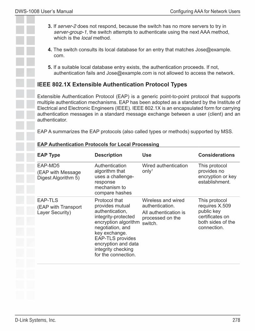
���
DWS-1008 User’s Manual
D-Link Systems, Inc.
Configuring AAA for Network Users
3. If server-2 does not respond, because the switch has no more servers to try in server-group-1, the switch attempts to authenticate using the next AAA method, which is the local method.
4. The switch consults its local database for an entry that matches [email protected].
5. If a suitable local database entry exists, the authentication proceeds. If not, authentication fails and [email protected] is not allowed to access the network.
IEEE 802.1X Extensible Authentication Protocol Types
Extensible Authentication Protocol (EAP) is a generic point-to-point protocol that supports multiple authentication mechanisms. EAP has been adopted as a standard by the Institute of Electrical and Electronic Engineers (IEEE). IEEE 802.1X is an encapsulated form for carrying authentication messages in a standard message exchange between a user (client) and an authenticator.
EAP A summarizes the EAP protocols (also called types or methods) supported by MSS. EAP Authentication Protocols for Local Processing
EAP Type Description Use Considerations
EAP-MD5(EAP with Message Digest Algorithm 5)
Authentication algorithm that uses a challenge-response mechanism to compare hashes
Wired authentication only1
This protocol provides no encryption or key establishment.
EAP-TLS(EAP with Transport Layer Security)
Protocol that provides mutual authentication, integrity-protected encryption algorithm negotiation, and key exchange. EAP-TLS provides encryption and data integrity checking for the connection.
Wireless and wired authentication.All authentication is processed on the switch.
This protocol requires X.509 public key certificates on both sides of the connection.
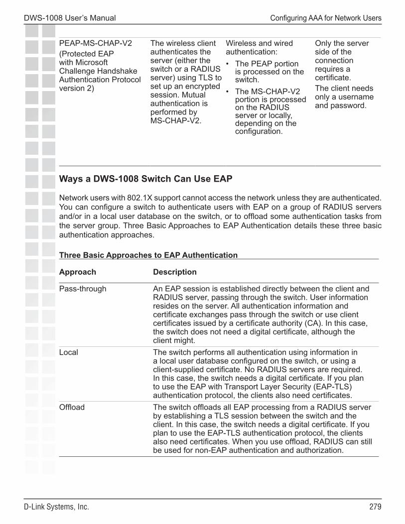
���
DWS-1008 User’s Manual
D-Link Systems, Inc.
Configuring AAA for Network Users
PEAP-MS-CHAP-V2(Protected EAP with Microsoft Challenge Handshake Authentication Protocol version 2)
The wireless client authenticates the server (either the switch or a RADIUS server) using TLS to set up an encrypted session. Mutual authentication is performed by MS-CHAP-V2.
Wireless and wired authentication:• The PEAP portion
is processed on the switch.
• The MS-CHAP-V2 portion is processed on the RADIUS server or locally, depending on the configuration.
Only the server side of the connection requires a certificate. The client needs only a username and password.
Ways a DWS-1008 Switch Can Use EAP
Network users with 802.1X support cannot access the network unless they are authenticated. You can configure a switch to authenticate users with EAP on a group of RADIUS servers and/or in a local user database on the switch, or to offload some authentication tasks from the server group. Three Basic Approaches to EAP Authentication details these three basic authentication approaches.
Three Basic Approaches to EAP Authentication
Approach Description
Pass-through An EAP session is established directly between the client and RADIUS server, passing through the switch. User information resides on the server. All authentication information and certificate exchanges pass through the switch or use client certificates issued by a certificate authority (CA). In this case, the switch does not need a digital certificate, although the client might.
Local The switch performs all authentication using information in a local user database configured on the switch, or using a client-supplied certificate. No RADIUS servers are required. In this case, the switch needs a digital certificate. If you plan to use the EAP with Transport Layer Security (EAP-TLS) authentication protocol, the clients also need certificates.
Offload The switch offloads all EAP processing from a RADIUS server by establishing a TLS session between the switch and the client. In this case, the switch needs a digital certificate. If you plan to use the EAP-TLS authentication protocol, the clients also need certificates. When you use offload, RADIUS can still be used for non-EAP authentication and authorization.
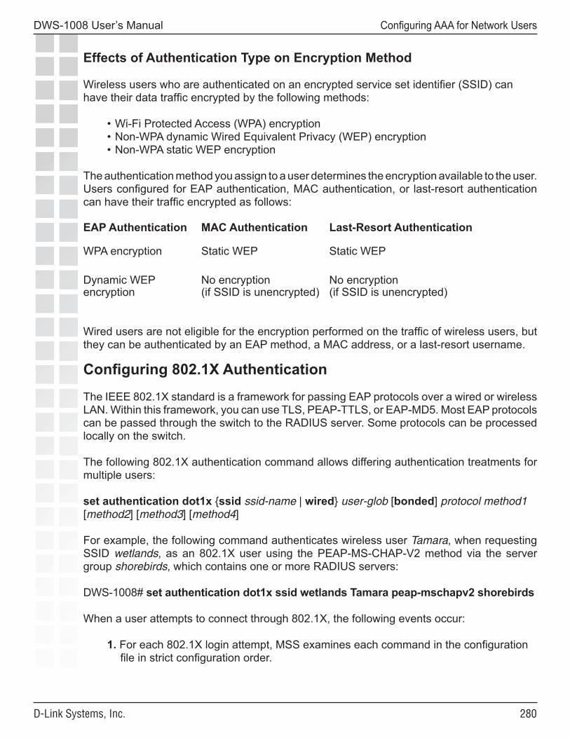
��0
DWS-1008 User’s Manual
D-Link Systems, Inc.
Configuring AAA for Network Users
Effects of Authentication Type on Encryption Method
Wireless users who are authenticated on an encrypted service set identifier (SSID) can have their data traffic encrypted by the following methods:
• Wi-Fi Protected Access (WPA) encryption • Non-WPA dynamic Wired Equivalent Privacy (WEP) encryption• Non-WPA static WEP encryption
The authentication method you assign to a user determines the encryption available to the user. Users configured for EAP authentication, MAC authentication, or last-resort authentication can have their traffic encrypted as follows:
EAP Authentication MAC Authentication Last-Resort Authentication
WPA encryption Static WEP Static WEP
Dynamic WEP encryption
No encryption (if SSID is unencrypted)
No encryption (if SSID is unencrypted)
Wired users are not eligible for the encryption performed on the traffic of wireless users, but they can be authenticated by an EAP method, a MAC address, or a last-resort username.
Configuring 802.1X Authentication
The IEEE 802.1X standard is a framework for passing EAP protocols over a wired or wireless LAN. Within this framework, you can use TLS, PEAP-TTLS, or EAP-MD5. Most EAP protocols can be passed through the switch to the RADIUS server. Some protocols can be processed locally on the switch.
The following 802.1X authentication command allows differing authentication treatments for multiple users:
set authentication dot1x {ssid ssid-name | wired} user-glob [bonded] protocol method1 [method2] [method3] [method4]
For example, the following command authenticates wireless user Tamara, when requesting SSID wetlands, as an 802.1X user using the PEAP-MS-CHAP-V2 method via the server group shorebirds, which contains one or more RADIUS servers:
DWS-1008# set authentication dot1x ssid wetlands Tamara peap-mschapv2 shorebirds
When a user attempts to connect through 802.1X, the following events occur:
1. For each 802.1X login attempt, MSS examines each command in the configuration file in strict configuration order.
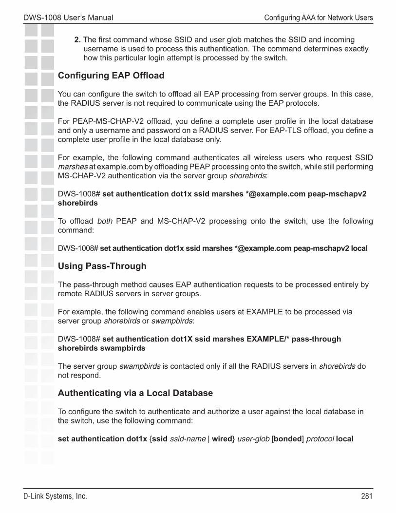
���
DWS-1008 User’s Manual
D-Link Systems, Inc.
Configuring AAA for Network Users
2. The first command whose SSID and user glob matches the SSID and incoming username is used to process this authentication. The command determines exactly how this particular login attempt is processed by the switch.
Configuring EAP Offload
You can configure the switch to offload all EAP processing from server groups. In this case, the RADIUS server is not required to communicate using the EAP protocols.
For PEAP-MS-CHAP-V2 offload, you define a complete user profile in the local database and only a username and password on a RADIUS server. For EAP-TLS offload, you define a complete user profile in the local database only.
For example, the following command authenticates all wireless users who request SSID marshes at example.com by offloading PEAP processing onto the switch, while still performing MS-CHAP-V2 authentication via the server group shorebirds:
DWS-1008# set authentication dot1x ssid marshes *@example.com peap-mschapv2 shorebirds
To offload both PEAP and MS-CHAP-V2 processing onto the switch, use the following command:
DWS-1008# set authentication dot1x ssid marshes *@example.com peap-mschapv2 local
Using Pass-Through
The pass-through method causes EAP authentication requests to be processed entirely by remote RADIUS servers in server groups.
For example, the following command enables users at EXAMPLE to be processed via server group shorebirds or swampbirds:
DWS-1008# set authentication dot1X ssid marshes EXAMPLE/* pass-through shorebirds swampbirds
The server group swampbirds is contacted only if all the RADIUS servers in shorebirds do not respond.
Authenticating via a Local Database
To configure the switch to authenticate and authorize a user against the local database in the switch, use the following command:
set authentication dot1x {ssid ssid-name | wired} user-glob [bonded] protocol local
���
DWS-1008 User’s Manual
D-Link Systems, Inc.
Configuring AAA for Network Users
For example, the following command authenticates 802.1X user Jose for wired authentication access via the local database:
DWS-1008# set authentication dot1X Jose wired peap-mschapv2 localsuccess: change accepted.
Binding User Authentication to Machine Authentication
Bonded Auth™ (bonded authentication) is a security feature that binds an 802.1X user’s authentication to authentication of the machine from which the user is attempting to log on. When this feature is enabled, MSS authenticates a user only if the machine from which the user logs on has already been authenticated separately.
By default, MSS does not bind user authentication to machine authentication. A trusted user can log on from any machine attached to the network.
You can use Bonded Auth with Microsoft Windows clients that support separate 802.1X authentication for the machine itself and for a user who uses the machine to log on to the network.
Network administrators sometimes use machine authentication in a Microsoft Active Directory domain to run login scripts, and to control defaults, application access and updates, and so on. Bonded Auth provides an added security measure, by ensuring that a trusted user can log onto the network only from a trusted machine known to Active Directory.
For example, if user bob.mycorp.com has a trusted laptop PC used for work but also has a personal laptop PC, you might want to bind Bob’s authentication with the authentication of his workplace laptop, host/bob-laptop.mycorp.com. In this case, Bob can log on to the company network only from his work laptop.
When Bonded Auth is enabled, MSS retains information about the machine’s session when a user logs on from that machine. MSS authenticates the user only if there has already been a successful machine authentication. Evidence of the machine’s session in MSS indicates that the machine has successfully authenticated and is therefore trusted by MSS. If MSS does not have session information for the machine, MSS refuses to authenticate the user and does not allow the user onto the network from the unauthenticated machine.
Note: If the 802.1X reauthentication parameter or the RADIUS Session-Timeout parameter is applicable, the user must log in before the 802.1X reauthentication timeout or the RADIUS session-timeout for the machine’s session expires. Normally, these parameters apply only to clients that use dynamic WEP, or use WEP-40 or WEP-104 encryption with WPA or RSN.
Authentication Rule RequirementsBonded Auth requires an 802.1X authentication rule for the machine itself, and a separate 802.1X authentication rule for the user(s). Use the bonded option in the user authentication rule, but not in the machine authentication rule.
���
DWS-1008 User’s Manual
D-Link Systems, Inc.
Configuring AAA for Network Users
The authentication rule for the machine must be higher up in the list of authentication rules than the authentication rule for the user.
You must use 802.1X authentication rules. The 802.1X authentication rule for the machine must use pass-through as the protocol. D-Link recommends that you also use pass-through for the user’s authentication rule.
The rule for the machine and the rule for the user must use a RADIUS server group as the method. (Generally, in a Bonded Auth configuration, the RADIUS servers will use a user database stored on an Active Directory server.)
D-Link recommends that you make the rules as general as possible. For example, if the Active Directory domain is mycorp.com, the following userglobs match on all machine names and users in the domain:
• host/*.mycorp.com (userglob for the machine authentication rule)• *.mycorp.com (userglob for the user authentication rule)
If the domain name has more nodes (for example, nl.mycorp.com), use an asterisk in each node that you want to match globally. For example, to match on all machines and users in mycorp.com, use the following userglobs:
• host/*.*.mycorp.com (userglob for the machine authentication rule)• *.*.mycorp.com (userglob for the user authentication rule)
Use more specific rules to direct machines and users to different server groups. For example, to direct users in nl.mycorp.com to a different server group than users in de.mycorp.com, use the following userglobs:
• host/*.nl.mycorp.com (userglob for the machine authentication rule)• *.nl.mycorp.com (userglob for the user authentication rule)• host/*.de.mycorp.com (userglob for the machine authentication rule)• *.de.mycorp.com (userglob for the user authentication rule)
Bonded Auth Period
The Bonded Auth period is the number of seconds MSS allows a Bonded Auth user to reauthenticate.
After successful machine authentication, a session for the machine appears in the session table in MSS. When the user logs on and is authenticated, the user session replaces the machine session in the table. However, since the user’s authentication rule contains the bonded option, MSS remembers that the machine was authenticated.
���
DWS-1008 User’s Manual
D-Link Systems, Inc.
Configuring AAA for Network Users
If a Bonded Auth user’s session is ended due to 802.1X reauthentication or the RADIUS Session-Timeout parameter, MSS can allow time for the user to reauthenticate. The amount of time that MSS allows for reauthentication is controlled by the Bonded Auth period. If the user does not reauthenticate within the Bonded Auth period, MSS deletes the information about the machine session. After the machine session information is deleted, the Bonded Auth user cannot reauthenticate. When this occurs, the user will need to log off, then log back on, to access the network. After multiple failed reauthentication attempts, the user might need to reboot the PC before logging on.
By default, the Bonded Auth period is 0 seconds. MSS does not wait for a Bonded Auth user to reauthenticate.
You can set the Bonded Auth period to a value up to 300 seconds. D-Link recommends that you try 60 seconds, and change the period to a longer value only if clients are unable to authenticate within 60 seconds.
To set the Bonded Auth period, use the following command:
set dot1x bonded-period seconds
To reset the Bonded Auth period to its default value (0), use the following command:
clear dot1x bonded-period
Bonded Auth Configuration Example
To configure Bonded Auth:
• Configure separate authentication rules for the machine and for the user(s).• Set the Bonded Auth period.• Verify the configuration changes.
The following commands configure two 802.1X authentication rules for access to SSID mycorp. The first rule is for authentication of all trusted laptop PCs at mycorp.com (host/*-laptop.mycorp.com). The second rule is for bonded authentication of all users at mycorp.com (*.mycorp.com). Both rules use pass-through as the protocol, and use RADIUS server group radgrp1.
DWS-1008# set authentication dot1x ssid mycorp host/*-laptop.mycorp.com pass-through radgrp1success: change accepted.
DWS-1008# set authentication dot1x ssid mycorp *.mycorp.com bonded pass-through radgrp1success: change accepted.
���
DWS-1008 User’s Manual
D-Link Systems, Inc.
Configuring AAA for Network Users
The following command sets the Bonded Auth period to 60 seconds, to allow time for WEP users to reauthenticate:
DWS-1008# set dot1x bonded-period 60success: change accepted.
Displaying Bonded Auth Configuration InformationTo display Bonded Auth configuration information, use the following command:
show dot1x config
In the following example, bob.mycorp.com uses Bonded Auth, and the Bonded Auth period is set to 60 seconds.
DWS-1008# show dot1x config
802.1X user policy----------------------‘host/bob-laptop.mycorp.com’ on ssid ‘mycorp’ doing PASSTHRU‘bob.mycorp.com’ on ssid ‘mycorp’ doing PASSTHRU (bonded)
802.1X parameter setting---------------- -------supplicant timeout 30auth-server timeout 30quiet period 60transmit period 5reauthentication period 3600maximum requests 2key transmission enabledreauthentication enabled authentication control enabled WEP rekey period 1800 WEP rekey enabled Bonded period 60
Information for the 802.1X authentication rule for the machine (host/bob-laptop.mycorp.com) is also displayed. However, the bonded option is configured only for the user’s authentication rule. The bonded option applies only to the authentication rules for users, not the authentication rules for machines.
Configuring Authentication and Authorization by MAC Address
You must sometimes authenticate users based on the MAC addresses of their devices rather than a username-password or certificate. For example, some Voice-over-IP (VoIP) phones and personal digital assistants (PDAs) do not support 802.1X authentication. If a client does not support 802.1X, MSS attempts to perform MAC authentication for the client instead. The switch can discover the MAC address of the device from received frames and can use the MAC address in place of a username for the client.
���
DWS-1008 User’s Manual
D-Link Systems, Inc.
Configuring AAA for Network Users
Users authorized by MAC address require a MAC authorization password if RADIUS authentication is desired. The default well-known password is dlink.
Caution: Use this method with care. IEEE 802.11 frames can be forged and can result in unauthorized network access if MAC authentication is employed.
Adding and Clearing MAC Users and User Groups Locally
MAC users and groups can gain network access only through the switch. They cannot create administrative connections to the switch. A MAC user is created in a similar fashion to other local users except for having a MAC address instead of a username. MAC user groups are created in a similar fashion to other local user groups.
(To create a MAC user profile or MAC user group on a RADIUS server, see the documentation for your RADIUS server.)
Adding MAC Users and Groups
To create a MAC user group in the local database, you must associate it with an authorization attribute and value. Use the following command:
set mac-usergroup group-name attr attribute-name value
For example, to create a MAC user group called mac-easters with a 3000-second Session-Timeout value, type the following command:
DWS-1008# set mac-usergroup mac-easters attr session-timeout 3000success: change accepted.
To configure a MAC user in the local database and optionally add the user to a group, use the following command:
set mac-user mac-addr [group group-name]
For example, type the following command to add MAC user 01:0f:03:04:05:06 to group macfans:
DWS-1008# set mac-user 01:0f:03:04:05:06 group macfanssuccess: change accepted.
Clearing MAC Users and Groups
To clear a MAC user from a user group, use the following command:
clear mac-user mac-addr group
���
DWS-1008 User’s Manual
D-Link Systems, Inc.
Configuring AAA for Network Users
For example, the following command removes MAC user 01:0f:03:04:05:06 from the group the user is in:
DWS-1008# clear mac-user 01:0f:03:04:05:06 group success: change accepted.
The clear mac-usergroup command removes the group.
To remove a MAC user profile from the local database on the switch, type the following command:
clear mac-user mac-address
For example, the following command removes MAC user 01:0f:03:04:05:06 from the local database:
DWS-1008# clear mac-user 01:0f:03:04:05:06success: change accepted.
Configuring MAC Authentication and Authorization
The set authentication mac command defines the AAA methods by which MAC addresses can be used for authentication. You can configure authentication for users through the MAC addresses of their devices with the following command:
set authentication mac {ssid ssid-name | wired} mac-addr-glob method1 [method2] [method3] [method4]
MAC addresses can be authenticated by either the switch’s local database or by a RADIUS server group. For example, the following command sets the authentication for MAC address 01:01:02:03:04:05 when requesting SSID voice, via the local database:
DWS-1008# set authentication mac ssid voice 01:01:02:03:04:05 localsuccess: change accepted
If the switch’s configuration does not contain a set authentication mac command that matches a non-802.1X client’s MAC address, MSS tries MAC authentication by default.
You can also glob MAC addresses. For example, the following command locally authenticates all MAC addresses that begin with the octets 01:01:02:
DWS-1008# set authentication mac ssid voice 01:01:02:* localsuccess: change accepted
You can add authorization attributes to authenticated MAC users with the following command:
set mac-user mac-addr attr attribute-name value
���
DWS-1008 User’s Manual
D-Link Systems, Inc.
Configuring AAA for Network Users
For example, to add the MAC user 00:01:02:03:04:05 to VLAN red:
DWS-1008# set mac-user 00:01:02:03:04:05 attr vlan-name redsuccess: change accepted
To change the value of an authorization attribute, reenter the command with the new value. To clear an authorization attribute from a MAC user profile in the local database, use the following command:
clear mac-user mac-addr attr attribute-name
For example, the following command clears the VLAN assignment from MAC user 01:0f:02:03:04:05:
DWS-1008# clear mac-user 01:0f:03:04:05:06 attr vlan-namesuccess: change accepted.
Changing the MAC Authorization Password for RADIUS
When you enable MAC authentication, the client does not supply a regular username or password. The MAC address of the user’s device is extracted from frames received from the device.
To authenticate and authorize MAC users via RADIUS, you must configure a single predefined password for MAC users, which is called the outbound authorization password. The same password is used for all MAC user entries in the RADIUS database. Set this password by typing the following command:
set radius server server-name author-password passwordThe default password is dlink.
Note: Before setting the outbound authorization password for a RADIUS server, you must have set the address for the RADIUS server.
For example, the following command sets the outbound authorization password for MAC users on server bigbird to h00per:
DWS-1008# set radius server bigbird author-password h00persuccess: change accepted.
Note: A MAC address must be dash-delimited in the RADIUS database (00-00-01-03-04-05). However, the MSS always displays colon-delimited MAC addresses.
If the MAC address is in the database, MSS uses the VLAN attribute and other attributes associated with it for user authorization. Otherwise, MSS tries the fallthru authentication type, which can be last-resort or none.
���
DWS-1008 User’s Manual
D-Link Systems, Inc.
Configuring AAA for Network Users
Configuring Last-Resort Access
Users who are not authenticated and authorized by 802.1X methods or a MAC address can gain limited access to the network as guest users. You can optionally configure a special username called last-resort-wired (for wired authentication access) or last-resort-ssid, where ssid is the SSID requested by the user. To match on the wildcard SSID name any, configure user last-resort-any, exactly as spelled here.
To configure a last-resort authentication rule, use the following command:
set authentication last-resort {ssid ssid-name | wired} method1 [method2] [method3] [method4]
For example, to enable wireless users who request SSID guestssid to join the network on VLAN k3, type the following commands:
DWS-1008# set authentication last-resort ssid guestssid localsuccess: change accepted
DWS-1008# set user last-resort-guestssid attr vlan-name k3success: change accepted
Note: Although MSS allows you to configure a user password for a last-resort user, the password has no effect. Last-resort users can never access a DWS-1008 switch in administrative mode and never require a password when authorized locally. However, if the last-resort user is authorized on a RADIUS server, the server might require a password. In this case, use the authorization password set on the switch, which is dlink by default.
Last-resort users configured on a RADIUS server require a password. Specify the authorization password (dlink by default.) To change the password, see Changing the MAC Authorization Password for RADIUS. This procedure also applies for last-resort users.
To ensure that your commands are configured, type the following command:
DWS-1008# show aaa...set authentication last-resort ssid guestssid local...user last-resort-guestssid vlan-name = k3
��0
DWS-1008 User’s Manual
D-Link Systems, Inc.
Configuring AAA for Network Users
Configuring AAA for Users of Third-Party APs
A switch can provide network access for users associated with a third-party AP that has authenticated the users with RADIUS. You can connect a third-party AP to a switch and configure the switch to provide authorization for clients who authenticate and access the network through the AP.
Authentication Process for Users of a Third-Party AP
1. MSS uses MAC authentication to authenticate the AP.
2. The user contacts the AP and negotiates the authentication protocol to be used.
3. The AP, acting as a RADIUS client, sends a RADIUS access-request to the switch. The access-request includes the SSID, the user’s MAC address, and the username.
4. For 802.1X users, the AP uses 802.1X to authenticate the user, using the switch as its RADIUS server. The proxies RADIUS requests from the AP to a real RADIUS server, depending on the authentication method specified in the proxy authentication rule for the user.
For non-802.1X users, the AP does not use 802.1X. The switch sends a RADIUS query for the special username last-resort-ssid, where ssid is the SSID name. The fallthru authentication type (last-resort) specified for the wired authentication port connected to the AP determines which username is used.
For any users of an AP that sends SSID traffic to the switch on an untagged VLAN, the switch does not use 802.1X. The switch sends a RADIUS query for the special username last-resort-wired, depending on the fallthru authentication type specified for the wired authentication port.
5. After successful RADIUS authentication of the user (or special username, for non-802.1X users), MSS assigns authorization attributes to the user from the RADIUS server’s access-accept response.
6. When the user’s session ends, the third-party AP sends a RADIUS stop-accounting record to the switch. The switch then removes the session.
���
DWS-1008 User’s Manual
D-Link Systems, Inc.
Configuring AAA for Network Users
Requirements
Third-Party AP Requirements
• The third-party AP must be connected to the switch through a wired Layer 2 link. MSS cannot provide data services if the AP and switch are in different Layer 3 subnets.
• The AP must be configured as the switch’s RADIUS client.• The AP must be configured so that all traffic for a given SSID is mapped to the same
802.1Q tagged VLAN. If the AP has multiple SSIDs, each SSID must use a different tag value.
• The AP must be configured to send the following information in a RADIUS access-request, for each user who wants to connect to the WLAN through the switch:
• SSID requested by the user. The SSID can be attached to the end of the called-station-id (per Congdon), or can be in a VSA (for example, cisco-vsa:ssid=r12-cisco-1).
• Calling-station-id that includes the user’s MAC address. The MAC address can be in any of the following formats:
❍ Separated by colons (for example, AA:BB:CC:DD:EE:FF)❍ Separated by dashes (for example, AA-BB-CC-DD-EE-FF)❍ Separated by dots (for example, AABB.CCDD.EEFF)
• Username• The AP must be configured to send a RADIUS stop-accounting record when a user’s
session ends.
Switch Requirements• The switch port connected to the third-party AP must be configured as a wired
authentication port. If SSID traffic from the AP is tagged, the same VLAN tag value must be used on the wired authentication port.
• A MAC authentication rule must be configured to authenticate the AP.• The switch must be configured as a RADIUS proxy for the AP. The switch is a
RADIUS server to the AP but remains a RADIUS client to the real RADIUS servers. • An authentication proxy rule must be configured for the AP’s users. The rule matches
based on SSID and username, and selects the authentication method (a RADIUS server group) for proxying.
RADIUS Server Requirements
• For 802.1X users, the usernames and passwords must be configured on the RADIUS server.
• For non-802.1X users of a tagged SSID, the special username last-resort-ssid must be configured, where ssid is the SSID name. The fallthru authentication type (last-resort) specified for the wired authentication port connected to the AP determines which username you need to configure.
• For any users of an untagged SSID, the special username last-resort-wired must be configured, depending on the fallthru authentication type specified for the wired authentication port.
���
DWS-1008 User’s Manual
D-Link Systems, Inc.
Configuring AAA for Network Users
Configuring Authentication for 802.1X Users of a Third-Party AP with Tagged SSIDs
To configure MSS to authenticate 802.1X users of a third-party AP, use the commands below to do the following:
• Configure the port connected to the AP as a wired authentication port. Use the following command:
set port type wired-auth port-list [tag tag-list] [max-sessions num] [auth-fall-thru {last-resort | none}]
• Configure a MAC authentication rule for the AP. Use the following command: set authentication mac wired mac-addr-glob method1
• Configure the switch port connected to the AP as a RADIUS proxy for the SSID supported by the AP. If SSID traffic from the AP is tagged, assign the same tag value to the switch port. Use the following command:
set radius proxy port port-list [tag tag-value] ssid ssid-name
• Add a RADIUS proxy entry for the AP. The proxy entry specifies the IP address of the AP and the UDP ports on which the switch listens for RADIUS access-requests and stop-accounting records from the AP. Use the following command:
set radius proxy client address ip-address [port udp-port-number] [acct-port acct-udp-port-number] key string
• Configure a proxy authentication rule for the AP’s users. Use the following command: set authentication proxy ssid ssid-name user-glob radius-server-group
For the port-list of the set port type wired-auth and set radius proxy port commands, specify the port(s) connected to the third-party AP.
For the ip-address of the set radius proxy client address command, specify the IP address of the RADIUS client (the third-party AP). For the udp-port-number, specify the UDP port on which the switch will listen for RADIUS access-requests. The default is UDP port 1812. For the acct-udp-port-number, specify the UDP port on which the switch will listen for RADIUS stop-accounting records. The default is UDP port 1813.
The following command configures ports 3 and 4 as wired authentication ports, and assigns tag value 104 to the ports:
DWS-1008# set port type wired-auth 3-4 tag 104success: change accepted.
You can specify multiple tag values. Specify the tag value for each SSID you plan to support.
���
DWS-1008 User’s Manual
D-Link Systems, Inc.
Configuring AAA for Network Users
The following command configures a MAC authentication rule that matches on the third-party AP’s MAC address. Because the AP is connected to the switch on a wired authentication port, the wired option is used.
DWS-1008# set authentication mac wired aa:bb:cc:01:01:01 srvrgrp1success: change accepted.
The following command maps SSID mycorp to packets received on port 3 or 4, using 802.1Q tag value 104:
DWS-1008# set radius proxy port 3-4 tag 104 ssid mycorpsuccess: change accepted.
Enter a separate command for each SSID, and its tag value, you want the switch to support. The following command configures a RADIUS proxy entry for a third-party AP RADIUS client at 10.20.20.9, sending RADIUS traffic to the default UDP ports 1812 and 1813 on the DWS-1008 switch:
DWS-1008# set radius proxy client address 10.20.20.9 key radkey1success: change accepted.
The IP address is the AP’s IP address. The key is the shared secret configured on the RADIUS servers. MSS uses the shared secret to authenticate and encrypt RADIUS communication.
The following command configures a proxy authentication rule that matches on all usernames associated with SSID mycorp. MSS uses RADIUS server group srvrgrp1 to proxy RADIUS requests and hence to authenticate and authorize the users.
DWS-1008# set authentication proxy ssid mycorp ** srvrgrp1
To verify the changes, use the show config area aaa command.
Configuring Authentication for Non-802.1X Users of a Third-Party AP with Tagged SSIDs
To configure MSS to authenticate non-802.1X users of a third-party AP, use the same commands as those required for 802.1X users. Additionally, when configuring the wired authentication port, use the auth-fall-thru option to change the fallthru authentication type to last-resort.
On the RADIUS server, configure username last-resort-ssid, depending on the fallthru authentication type you specify for the wired authentication port.
���
DWS-1008 User’s Manual
D-Link Systems, Inc.
Configuring AAA for Network Users
Configuring Access for Any Users of a Non-Tagged SSID
If SSID traffic from the third-party AP is untagged, use the same configuration commands as the ones required for 802.1X users, except the set radius proxy port command. This command is not required and is not applicable to untagged SSID traffic. In addition, when configuring the wired authentication port, use the auth-fall-thru option to change the fallthru authentication type to last-resort.
On the RADIUS server, configure username last-resort-wired, depending on the fallthru authentication type specified for the wired authentication port.
Assigning Authorization Attributes
Authorization attributes can be assigned to users in the local database or on remote servers. The attributes, which include access control list (ACL) filters, VLAN membership, encryption type, session time-out period, and other session characteristics, let you control how and when users access the network. When a user or group is authenticated, the local database or RADIUS server passes the authorization attributes to MSS to characterize the user’s session.
The VLAN attribute is required. MSS can authorize a user to access the network only if the VLAN to place the user on is specified.
The table below lists the authorization attributes supported by MSS. (For brief descriptions of all the RADIUS attributes and D-link vendor-specific attributes supported by MSS, as well as the vendor ID and types for D-link VSAs configured on a RADIUS server, see Appendix B, “Supported RADIUS Attributes”).
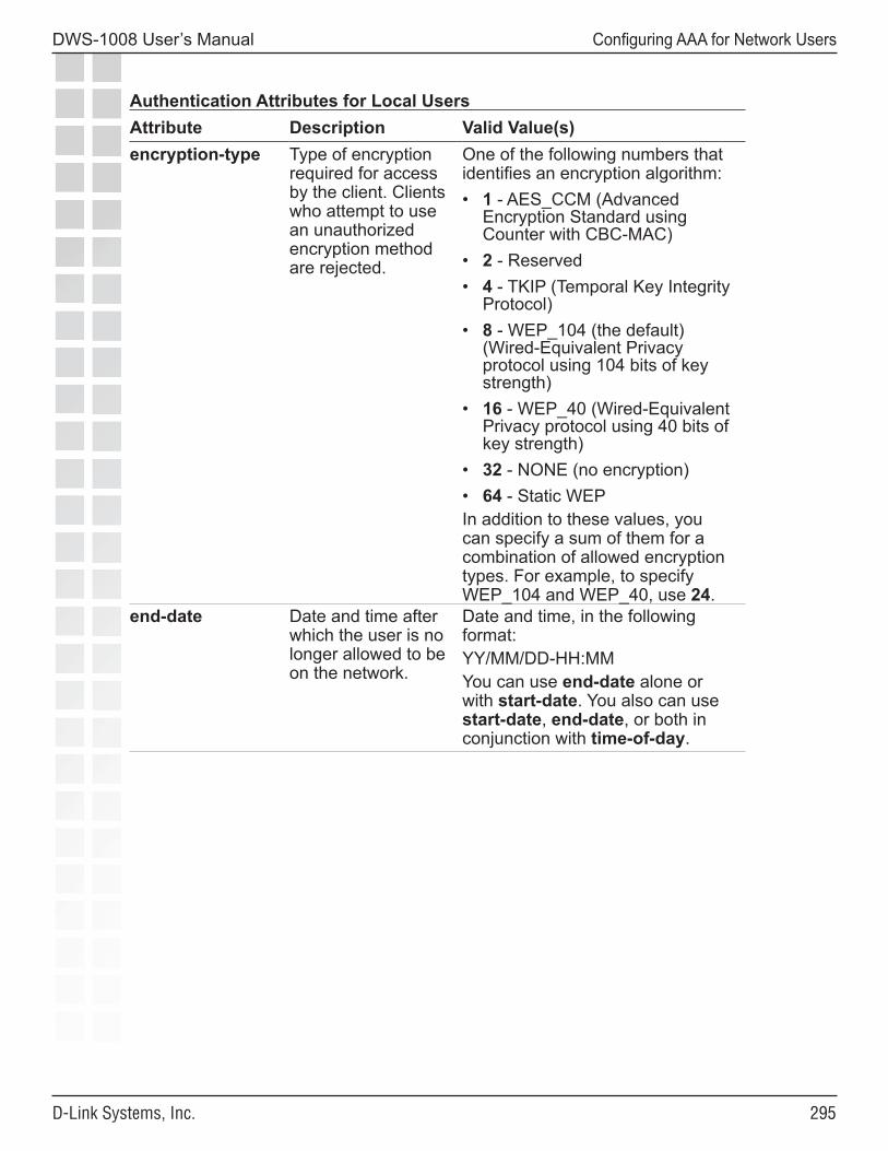
���
DWS-1008 User’s Manual
D-Link Systems, Inc.
Configuring AAA for Network Users
Authentication Attributes for Local Users Attribute Description Valid Value(s)encryption-type Type of encryption
required for access by the client. Clients who attempt to use an unauthorized encryption method are rejected.
One of the following numbers that identifies an encryption algorithm:• 1 - AES_CCM (Advanced
Encryption Standard using Counter with CBC-MAC)
• 2 - Reserved• 4 - TKIP (Temporal Key Integrity
Protocol)• 8 - WEP_104 (the default)
(Wired-Equivalent Privacy protocol using 104 bits of key strength)
• 16 - WEP_40 (Wired-Equivalent Privacy protocol using 40 bits of key strength)
• 32 - NONE (no encryption)• 64 - Static WEPIn addition to these values, you can specify a sum of them for a combination of allowed encryption types. For example, to specify WEP_104 and WEP_40, use 24.
end-date Date and time after which the user is no longer allowed to be on the network.
Date and time, in the following format:YY/MM/DD-HH:MMYou can use end-date alone or with start-date. You also can use start-date, end-date, or both in conjunction with time-of-day.
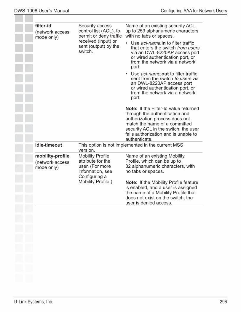
���
DWS-1008 User’s Manual
D-Link Systems, Inc.
Configuring AAA for Network Users
filter-id(network access mode only)
Security access control list (ACL), to permit or deny traffic received (input) or sent (output) by the switch.
Name of an existing security ACL, up to 253 alphanumeric characters, with no tabs or spaces. • Use acl-name.in to filter traffic
that enters the switch from users via an DWL-8220AP access port or wired authentication port, or from the network via a network port.
• Use acl-name.out to filter traffic sent from the switch to users via an DWL-8220AP access port or wired authentication port, or from the network via a network port.
Note: If the Filter-Id value returned through the authentication and authorization process does not match the name of a committed security ACL in the switch, the user fails authorization and is unable to authenticate.
idle-timeout This option is not implemented in the current MSS version.
mobility-profile(network access mode only)
Mobility Profile attribute for the user. (For more information, see Configuring a Mobility Profile.)
Name of an existing Mobility Profile, which can be up to 32 alphanumeric characters, with no tabs or spaces.
Note: If the Mobility Profile feature is enabled, and a user is assigned the name of a Mobility Profile that does not exist on the switch, the user is denied access.
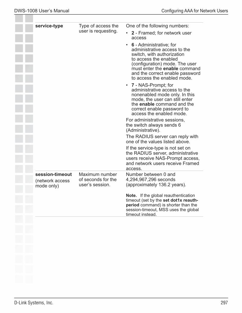
���
DWS-1008 User’s Manual
D-Link Systems, Inc.
Configuring AAA for Network Users
service-type Type of access the user is requesting.
One of the following numbers:• 2 - Framed; for network user
access• 6 - Administrative; for
administrative access to the switch, with authorization to access the enabled (configuration) mode. The user must enter the enable command and the correct enable password to access the enabled mode.
• 7 - NAS-Prompt; for administrative access to the nonenabled mode only. In this mode, the user can still enter the enable command and the correct enable password to access the enabled mode.
For administrative sessions, the switch always sends 6 (Administrative). The RADIUS server can reply with one of the values listed above.If the service-type is not set on the RADIUS server, administrative users receive NAS-Prompt access, and network users receive Framed access.
session-timeout(network access mode only)
Maximum number of seconds for the user’s session.
Number between 0 and 4,294,967,296 seconds (approximately 136.2 years).
Note. If the global reauthentication timeout (set by the set dot1x reauth-period command) is shorter than the session-timeout, MSS uses the global timeout instead.
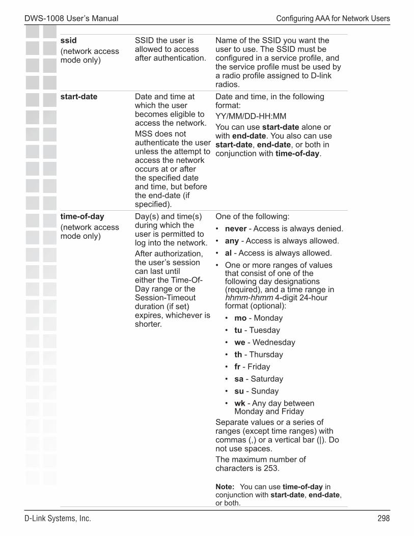
���
DWS-1008 User’s Manual
D-Link Systems, Inc.
Configuring AAA for Network Users
ssid(network access mode only)
SSID the user is allowed to access after authentication.
Name of the SSID you want the user to use. The SSID must be configured in a service profile, and the service profile must be used by a radio profile assigned to D-link radios.
start-date Date and time at which the user becomes eligible to access the network.MSS does not authenticate the user unless the attempt to access the network occurs at or after the specified date and time, but before the end-date (if specified).
Date and time, in the following format:YY/MM/DD-HH:MMYou can use start-date alone or with end-date. You also can use start-date, end-date, or both in conjunction with time-of-day.
time-of-day(network access mode only)
Day(s) and time(s) during which the user is permitted to log into the network. After authorization, the user’s session can last until either the Time-Of-Day range or the Session-Timeout duration (if set) expires, whichever is shorter.
One of the following:• never - Access is always denied.• any - Access is always allowed.• al - Access is always allowed.• One or more ranges of values
that consist of one of the following day designations (required), and a time range in hhmm-hhmm 4-digit 24-hour format (optional):• mo - Monday• tu - Tuesday• we - Wednesday• th - Thursday• fr - Friday• sa - Saturday• su - Sunday• wk - Any day between
Monday and FridaySeparate values or a series of ranges (except time ranges) with commas (,) or a vertical bar (|). Do not use spaces.The maximum number of characters is 253.
Note: You can use time-of-day in conjunction with start-date, end-date, or both.
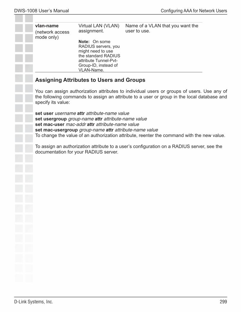
���
DWS-1008 User’s Manual
D-Link Systems, Inc.
Configuring AAA for Network Users
vlan-name(network access mode only)
Virtual LAN (VLAN) assignment.
Note: On some RADIUS servers, you might need to use the standard RADIUS attribute Tunnel-Pvt-Group-ID, instead of VLAN-Name.
Name of a VLAN that you want the user to use.
Assigning Attributes to Users and Groups
You can assign authorization attributes to individual users or groups of users. Use any of the following commands to assign an attribute to a user or group in the local database and specify its value:
set user username attr attribute-name valueset usergroup group-name attr attribute-name valueset mac-user mac-addr attr attribute-name valueset mac-usergroup group-name attr attribute-name valueTo change the value of an authorization attribute, reenter the command with the new value.
To assign an authorization attribute to a user’s configuration on a RADIUS server, see the documentation for your RADIUS server.
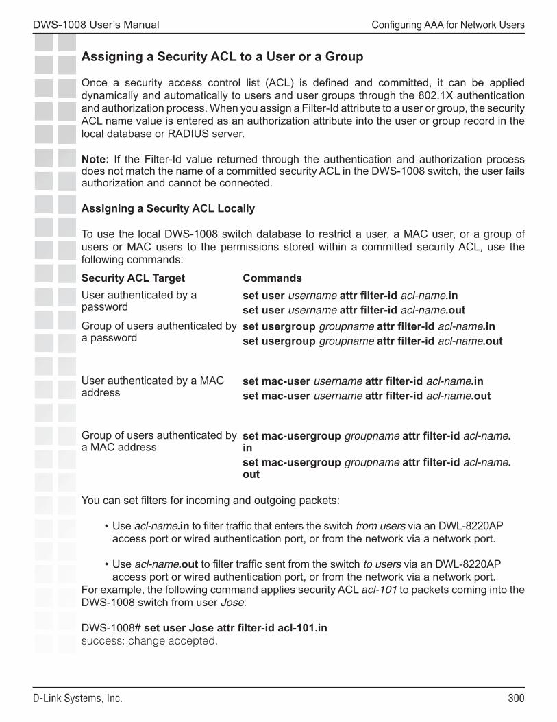
�00
DWS-1008 User’s Manual
D-Link Systems, Inc.
Configuring AAA for Network Users
Assigning a Security ACL to a User or a Group
Once a security access control list (ACL) is defined and committed, it can be applied dynamically and automatically to users and user groups through the 802.1X authentication and authorization process. When you assign a Filter-Id attribute to a user or group, the security ACL name value is entered as an authorization attribute into the user or group record in the local database or RADIUS server.
Note: If the Filter-Id value returned through the authentication and authorization process does not match the name of a committed security ACL in the DWS-1008 switch, the user fails authorization and cannot be connected.
Assigning a Security ACL Locally
To use the local DWS-1008 switch database to restrict a user, a MAC user, or a group of users or MAC users to the permissions stored within a committed security ACL, use the following commands:
Security ACL Target CommandsUser authenticated by a password
set user username attr filter-id acl-name.inset user username attr filter-id acl-name.out
Group of users authenticated by a password
set usergroup groupname attr filter-id acl-name.inset usergroup groupname attr filter-id acl-name.out
User authenticated by a MAC address
set mac-user username attr filter-id acl-name.inset mac-user username attr filter-id acl-name.out
Group of users authenticated by a MAC address
set mac-usergroup groupname attr filter-id acl-name.inset mac-usergroup groupname attr filter-id acl-name.out
You can set filters for incoming and outgoing packets:
• Use acl-name.in to filter traffic that enters the switch from users via an DWL-8220AP access port or wired authentication port, or from the network via a network port.
• Use acl-name.out to filter traffic sent from the switch to users via an DWL-8220AP access port or wired authentication port, or from the network via a network port.
For example, the following command applies security ACL acl-101 to packets coming into the DWS-1008 switch from user Jose:
DWS-1008# set user Jose attr filter-id acl-101.insuccess: change accepted.
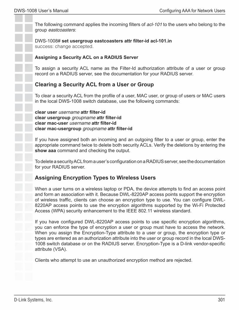
�0�
DWS-1008 User’s Manual
D-Link Systems, Inc.
Configuring AAA for Network Users
The following command applies the incoming filters of acl-101 to the users who belong to the group eastcoasters:
DWS-1008# set usergroup eastcoasters attr filter-id acl-101.insuccess: change accepted.
Assigning a Security ACL on a RADIUS Server
To assign a security ACL name as the Filter-Id authorization attribute of a user or group record on a RADIUS server, see the documentation for your RADIUS server.
Clearing a Security ACL from a User or Group
To clear a security ACL from the profile of a user, MAC user, or group of users or MAC users in the local DWS-1008 switch database, use the following commands:
clear user username attr filter-idclear usergroup groupname attr filter-idclear mac-user username attr filter-idclear mac-usergroup groupname attr filter-id
If you have assigned both an incoming and an outgoing filter to a user or group, enter the appropriate command twice to delete both security ACLs. Verify the deletions by entering the show aaa command and checking the output.
To delete a security ACL from a user’s configuration on a RADIUS server, see the documentation for your RADIUS server.
Assigning Encryption Types to Wireless Users
When a user turns on a wireless laptop or PDA, the device attempts to find an access point and form an association with it. Because DWL-8220AP access points support the encryption of wireless traffic, clients can choose an encryption type to use. You can configure DWL-8220AP access points to use the encryption algorithms supported by the Wi-Fi Protected Access (WPA) security enhancement to the IEEE 802.11 wireless standard.
If you have configured DWL-8220AP access points to use specific encryption algorithms, you can enforce the type of encryption a user or group must have to access the network. When you assign the Encryption-Type attribute to a user or group, the encryption type or types are entered as an authorization attribute into the user or group record in the local DWS-1008 switch database or on the RADIUS server. Encryption-Type is a D-link vendor-specific attribute (VSA).
Clients who attempt to use an unauthorized encryption method are rejected.
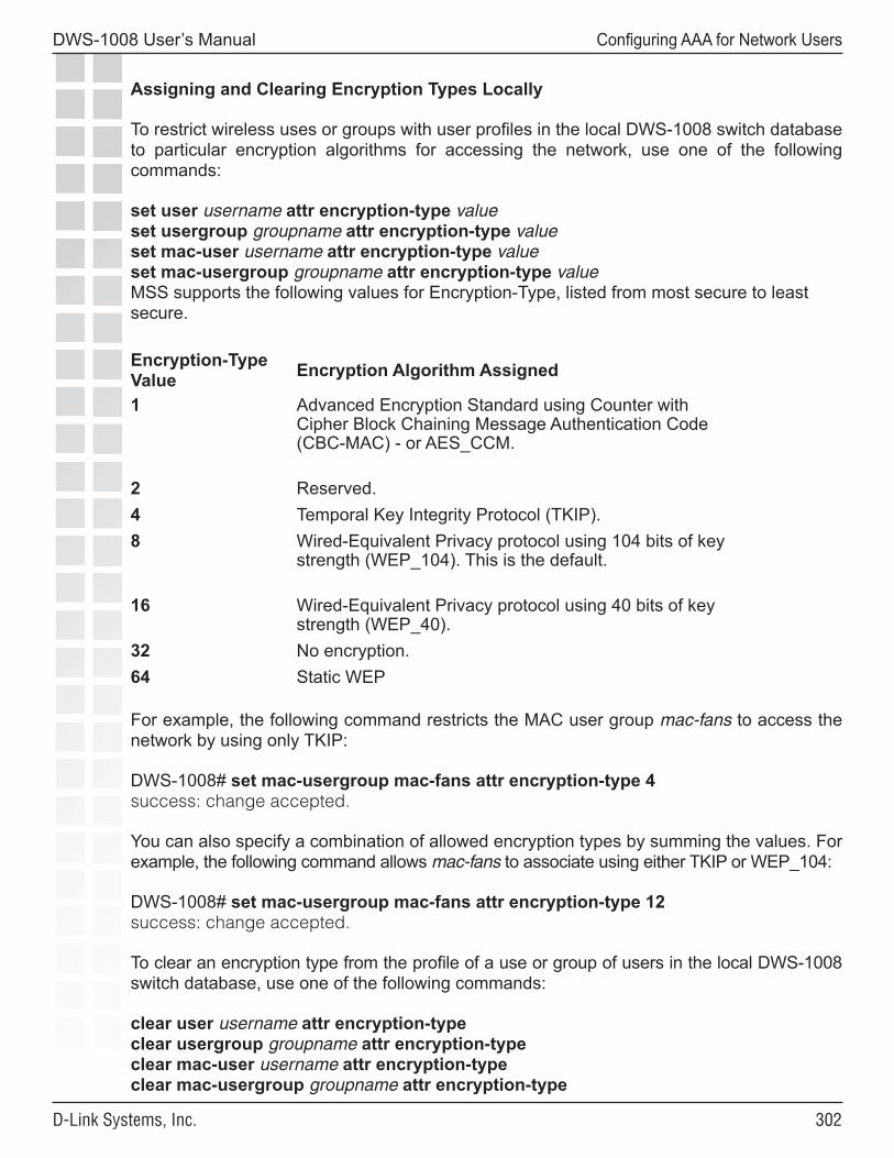
�0�
DWS-1008 User’s Manual
D-Link Systems, Inc.
Configuring AAA for Network Users
Assigning and Clearing Encryption Types Locally
To restrict wireless uses or groups with user profiles in the local DWS-1008 switch database to particular encryption algorithms for accessing the network, use one of the following commands:
set user username attr encryption-type valueset usergroup groupname attr encryption-type valueset mac-user username attr encryption-type valueset mac-usergroup groupname attr encryption-type valueMSS supports the following values for Encryption-Type, listed from most secure to least secure. Encryption-Type Value Encryption Algorithm Assigned
1 Advanced Encryption Standard using Counter with Cipher Block Chaining Message Authentication Code (CBC-MAC) - or AES_CCM.
2 Reserved.4 Temporal Key Integrity Protocol (TKIP).8 Wired-Equivalent Privacy protocol using 104 bits of key
strength (WEP_104). This is the default.
16 Wired-Equivalent Privacy protocol using 40 bits of key strength (WEP_40).
32 No encryption.64 Static WEP
For example, the following command restricts the MAC user group mac-fans to access the network by using only TKIP:
DWS-1008# set mac-usergroup mac-fans attr encryption-type 4success: change accepted.
You can also specify a combination of allowed encryption types by summing the values. For example, the following command allows mac-fans to associate using either TKIP or WEP_104:
DWS-1008# set mac-usergroup mac-fans attr encryption-type 12success: change accepted.
To clear an encryption type from the profile of a use or group of users in the local DWS-1008 switch database, use one of the following commands:
clear user username attr encryption-typeclear usergroup groupname attr encryption-typeclear mac-user username attr encryption-typeclear mac-usergroup groupname attr encryption-type
�0�
DWS-1008 User’s Manual
D-Link Systems, Inc.
Configuring AAA for Network Users
Assigning and Clearing Encryption Types on a RADIUS Server
To assign or delete an encryption algorithm as the Encryption-Type authorization attribute in a user or group record on a RADIUS server, see the documentation for your RADIUS server.
Overriding or Adding Attributes Locally with a Location Policy
During the login process, the AAA authorization process is started immediately after clients are authenticated to use the switch. During authorization, MSS assigns the user to a VLAN and applies optional user attributes, such as a session timeout value and one or more security ACL filters.
A location policy is a set of rules that enables you to locally set or change authorization attributes for a user after the user is authorized by AAA, without making changes to the AAA server. For example, you might want to enforce VLAN membership and security ACL policies on a particular DWS-1008 switch based on a client’s organization or physical location, or assign a VLAN to users who have no AAA assignment. For these situations, you can configure the location policy on the switch.
You can use a location policy to locally set or change the Filter-Id and VLAN-Name authorization attributes obtained from AAA.
About the Location Policy
Each switch can have one location policy. The location policy consists of a set of rules. Each rule contains conditions, and an action to perform if all conditions in the rule match. The action can be one of the following:
• Deny access to the network• Permit access, but set or change the user’s VLAN assignment, inbound ACL,
outbound ACL, or any combination of these attributes
The conditions can be one or more of the following:
• AAA-assigned VLAN• Username• AP access port, Distributed AP number, or wired authentication port through which
the user accessed the network• SSID name with which the user is associated
Conditions within a rule are ANDed. All conditions in the rule must match in order for MSS to take the specified action. If the location policy contains multiple rules, MSS compares the user information to the rules one at a time, in the order the rules appear in the switch’s configuration file, beginning with the rule at the top of the list. MSS continues comparing until a user matches all conditions in a rule or until there are no more rules.
Any authorization attributes not changed by the location policy remain active.
�0�
DWS-1008 User’s Manual
D-Link Systems, Inc.
Configuring AAA for Network Users
How the Location Policy Differs from a Security ACL
Although structurally similar, the location policy and security ACLs have different functions. The location policy on a switch can be used to locally redirect a user to a different VLAN or locally control the traffic to and from a user.
In contrast, security ACLs are packet filters applied to the user throughout a MobileLAN. You can use the location policy to locally apply a security ACL to a user.
Setting the Location Policy
To enable the location policy function on a switch, you must create at least one location policy rule with one of the following commands:
set location policy deny if {ssid operator ssid-name | vlan operator vlan-glob | user operator user-glob | port port-list | dap dap-num} [before rule-number | modify rule-number]set location policy permit {vlan vlan-name | inacl inacl-name | outacl outacl-name} if {ssid operator ssid-name | vlan operator vlan-glob | user operator user-glob | port port-list | dap dap-num} [before rule-number | modify rule-number]
You must specify whether to permit or deny access, and you must identify a VLAN, username, or access port to match. Use one of the following operators to specify how the rule must match the VLAN or username:
• eq - Applies the location policy rule to all users assigned VLAN names matching vlan-glob or having usernames that match user-glob.
(Like a user glob, a VLAN glob is a way to group VLANs for use in this command.)
•neq - Applies the location policy rule to all users assigned VLAN names not matching vlan-glob or having usernames that do not match user-glob.
For example, the following command denies network access to all users matching *.theirfirm.com, causing them to fail authorization:
DWS-1008# set location policy deny if user eq *.theirfirm.com
The following command authorizes access to the guest_1 VLAN for all users who do not match *.ourfirm.com:
DWS-1008# set location policy permit vlan guest_1 if user neq *.ourfirm.com
The following command places all users who are authorized for SSID tempvendor_a into VLAN kiosk_1:
DWS-1008# set location policy permit vlan kiosk_1 if ssid eq tempvendor_asuccess: change accepted.
�0�
DWS-1008 User’s Manual
D-Link Systems, Inc.
Configuring AAA for Network Users
Applying Security ACLs in a Location Policy Rule
When reassigning security ACL filters, specify whether the filter is an input filter or an output filter, as follows:
• Input filter - Use inacl inacl-name to filter traffic that enters the switch from users via a DWL-8220AP access port or wired authentication port, or from the network via a network port.
• Output filter - Use outacl outacl-name to filter traffic sent from the switch to users via a DWL-8220AP access port or wired authentication port, or from the network via a network port.
For example, the following command authorizes users at *.ny.ourfirm.com to access the bld4.tac VLAN, and applies the security ACL tac_24 to the traffic they receive:
DWS-1008# set location policy permit vlan bld4.tac outacl tac_24 if user eq *.ny.ourfirm.com
The following command authorizes access to users on VLANs with names matching bld4.* and applies security ACLs svcs_2 to the traffic they send and svcs_3 to the traffic they receive:
DWS-1008# set location policy permit inacl svcs_2 outacl svcs_3 if vlan eq bldg4.*
You can optionally add the suffixes .in and .out to inacl-name and outacl-name for consistency with their usage in entries stored in the local DWS-1008 switch database.
Displaying and Positioning Location Policy Rules
The order of location policy rules is significant. MSS checks a location policy rule that is higher in the list before those lower in the list. Rules are listed in the order in which you create them, unless you move them.
To position location policy rules within the location policy, use before rule-number and modify rule-number in the set location policy command, or use the clear location policy rule-number command.
For example, suppose you have configured the following location policy rules:
DWS-1008 show location policyId Clauses----------------------------------------------------------------1) deny if user eq *.theirfirm.com2) permit vlan guest_1 if vlan neq *.ourfirm.com3) permit vlan bld4.tac inacl tac_24.in if user eq *.ny.ourfirm.com4) permit inacl svcs_2.in outacl svcs_3.out if vlan eq bldg4.*
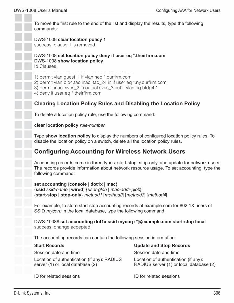
�0�
DWS-1008 User’s Manual
D-Link Systems, Inc.
Configuring AAA for Network Users
To move the first rule to the end of the list and display the results, type the following commands:
DWS-1008 clear location policy 1success: clause 1 is removed.
DWS-1008 set location policy deny if user eq *.theirfirm.comDWS-1008 show location policyId Clauses----------------------------------------------------------------1) permit vlan guest_1 if vlan neq *.ourfirm.com2) permit vlan bld4.tac inacl tac_24.in if user eq *.ny.ourfirm.com3) permit inacl svcs_2.in outacl svcs_3.out if vlan eq bldg4.*4) deny if user eq *.theirfirm.com
Clearing Location Policy Rules and Disabling the Location Policy
To delete a location policy rule, use the following command:
clear location policy rule-number
Type show location policy to display the numbers of configured location policy rules. To disable the location policy on a switch, delete all the location policy rules.
Configuring Accounting for Wireless Network Users
Accounting records come in three types: start-stop, stop-only, and update for network users. The records provide information about network resource usage. To set accounting, type the following command:
set accounting {console | dot1x | mac} {ssid ssid-name | wired} {user-glob | mac-addr-glob} {start-stop | stop-only} method1 [method2] [method3] [method4]
For example, to store start-stop accounting records at example.com for 802.1X users of SSID mycorp in the local database, type the following command:
DWS-1008# set accounting dot1x ssid mycorp *@example.com start-stop localsuccess: change accepted.
The accounting records can contain the following session information:
Start Records Update and Stop RecordsSession date and time Session date and timeLocation of authentication (if any): RADIUS server (1) or local database (2)
Location of authentication (if any): RADIUS server (1) or local database (2)
ID for related sessions ID for related sessions
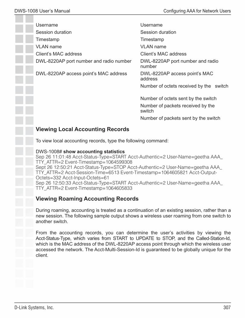
�0�
DWS-1008 User’s Manual
D-Link Systems, Inc.
Configuring AAA for Network Users
Username UsernameSession duration Session durationTimestamp TimestampVLAN name VLAN nameClient’s MAC address Client’s MAC addressDWL-8220AP port number and radio number DWL-8220AP port number and radio
numberDWL-8220AP access point’s MAC address DWL-8220AP access point’s MAC
addressNumber of octets received by the switch
Number of octets sent by the switchNumber of packets received by the switchNumber of packets sent by the switch
Viewing Local Accounting Records
To view local accounting records, type the following command:
DWS-1008# show accounting statisticsSep 26 11:01:48 Acct-Status-Type=START Acct-Authentic=2 User-Name=geetha AAA_TTY_ATTR=2 Event-Timestamp=1064599308Sept 26 12:50:21 Acct-Status-Type=STOP Acct-Authentic=2 User-Name=geetha AAA_TTY_ATTR=2 Acct-Session-Time=6513 Event-Timestamp=1064605821 Acct-Output-Octets=332 Acct-Input-Octets=61Sep 26 12:50:33 Acct-Status-Type=START Acct-Authentic=2 User-Name=geetha AAA_TTY_ATTR=2 Event-Timestamp=1064605833
Viewing Roaming Accounting Records
During roaming, accounting is treated as a continuation of an existing session, rather than a new session. The following sample output shows a wireless user roaming from one switch to another switch.
From the accounting records, you can determine the user’s activities by viewing the Acct-Status-Type, which varies from START to UPDATE to STOP, and the Called-Station-Id, which is the MAC address of the DWL-8220AP access point through which the wireless user accessed the network. The Acct-Multi-Session-Id is guaranteed to be globally unique for the client.
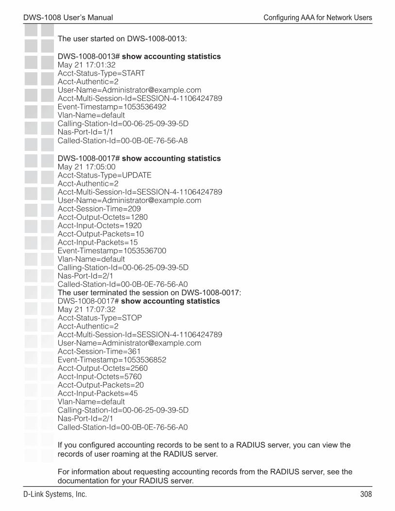
�0�
DWS-1008 User’s Manual
D-Link Systems, Inc.
Configuring AAA for Network Users
The user started on DWS-1008-0013:
DWS-1008-0013# show accounting statisticsMay 21 17:01:32Acct-Status-Type=STARTAcct-Authentic=2User-Name=Administrator@example.comAcct-Multi-Session-Id=SESSION-4-1106424789Event-Timestamp=1053536492Vlan-Name=defaultCalling-Station-Id=00-06-25-09-39-5DNas-Port-Id=1/1Called-Station-Id=00-0B-0E-76-56-A8
DWS-1008-0017# show accounting statisticsMay 21 17:05:00Acct-Status-Type=UPDATEAcct-Authentic=2Acct-Multi-Session-Id=SESSION-4-1106424789User-Name=Administrator@example.comAcct-Session-Time=209Acct-Output-Octets=1280Acct-Input-Octets=1920Acct-Output-Packets=10Acct-Input-Packets=15Event-Timestamp=1053536700Vlan-Name=defaultCalling-Station-Id=00-06-25-09-39-5DNas-Port-Id=2/1Called-Station-Id=00-0B-0E-76-56-A0The user terminated the session on DWS-1008-0017:DWS-1008-0017# show accounting statisticsMay 21 17:07:32Acct-Status-Type=STOPAcct-Authentic=2Acct-Multi-Session-Id=SESSION-4-1106424789User-Name=Administrator@example.comAcct-Session-Time=361Event-Timestamp=1053536852Acct-Output-Octets=2560Acct-Input-Octets=5760Acct-Output-Packets=20Acct-Input-Packets=45Vlan-Name=defaultCalling-Station-Id=00-06-25-09-39-5DNas-Port-Id=2/1Called-Station-Id=00-0B-0E-76-56-A0
If you configured accounting records to be sent to a RADIUS server, you can view the records of user roaming at the RADIUS server. For information about requesting accounting records from the RADIUS server, see the documentation for your RADIUS server.

�0�
DWS-1008 User’s Manual
D-Link Systems, Inc.
Configuring AAA for Network Users
Displaying the AAA Configuration
To view the results of the AAA commands you have set and verify their order, type the show aaa command. The order in which the commands appear in the output determines the order in which MSS matches them to users.
(Sometimes the order might not be what you intended. See Avoiding AAA Problems in Configuration Order.)
For example:
DWS-1008# show aaaDefault Valuesauthport=1812 acctport=1813 timeout=5 acct-timeout=5retrans=3 deadtime=0 key=(null) author-pass=(null)Radius ServersServer Addr Ports T/o Tries Dead State------------------------------------------------------------------------------------------------------------rs-3 198.162.1.1 1821 1813 5 3 0 UPrs-4 198.168.1.2 1821 1813 77 11 2 UPrs-5 198.162.1.3 1821 1813 42 23 0 UPServer groupssg1: rs-3sg2: rs-4sg3: rs-5
set authentication console * noneset authentication mac ssid mycorp * localset authentication dot1x ssid mycorp Geetha eap-tlsset authentication dot1x ssid mycorp * peap-mschapv2 sg1 sg2 sg3set accounting dot1x Nin ssid mycorp stop-only sg2set accounting admin Natasha start-stop localset authentication last-resort ssid guestssid local
user NinPassword = 082c6c64060b (encrypted)Filter-Id = acl-999.inFilter-Id = acl-999.outuser last-resort-guestssidVlan-Name = k2mac-user 01:02:03:04:05:06usergroup eastcoasters session-timeout = 99
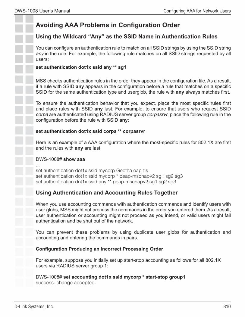
��0
DWS-1008 User’s Manual
D-Link Systems, Inc.
Configuring AAA for Network Users
Avoiding AAA Problems in Configuration Order
Using the Wildcard “Any” as the SSID Name in Authentication Rules
You can configure an authentication rule to match on all SSID strings by using the SSID string any in the rule. For example, the following rule matches on all SSID strings requested by all users:
set authentication dot1x ssid any ** sg1
MSS checks authentication rules in the order they appear in the configuration file. As a result, if a rule with SSID any appears in the configuration before a rule that matches on a specific SSID for the same authentication type and userglob, the rule with any always matches first.
To ensure the authentication behavior that you expect, place the most specific rules first and place rules with SSID any last. For example, to ensure that users who request SSID corpa are authenticated using RADIUS server group corpasrvr, place the following rule in the configuration before the rule with SSID any:
set authentication dot1x ssid corpa ** corpasrvr
Here is an example of a AAA configuration where the most-specific rules for 802.1X are first and the rules with any are last:
DWS-1008# show aaa...set authentication dot1x ssid mycorp Geetha eap-tlsset authentication dot1x ssid mycorp * peap-mschapv2 sg1 sg2 sg3set authentication dot1x ssid any ** peap-mschapv2 sg1 sg2 sg3
Using Authentication and Accounting Rules Together
When you use accounting commands with authentication commands and identify users with user globs, MSS might not process the commands in the order you entered them. As a result, user authentication or accounting might not proceed as you intend, or valid users might fail authentication and be shut out of the network.
You can prevent these problems by using duplicate user globs for authentication and accounting and entering the commands in pairs.
Configuration Producing an Incorrect Processing Order
For example, suppose you initially set up start-stop accounting as follows for all 802.1X users via RADIUS server group 1:
DWS-1008# set accounting dot1x ssid mycorp * start-stop group1success: change accepted.
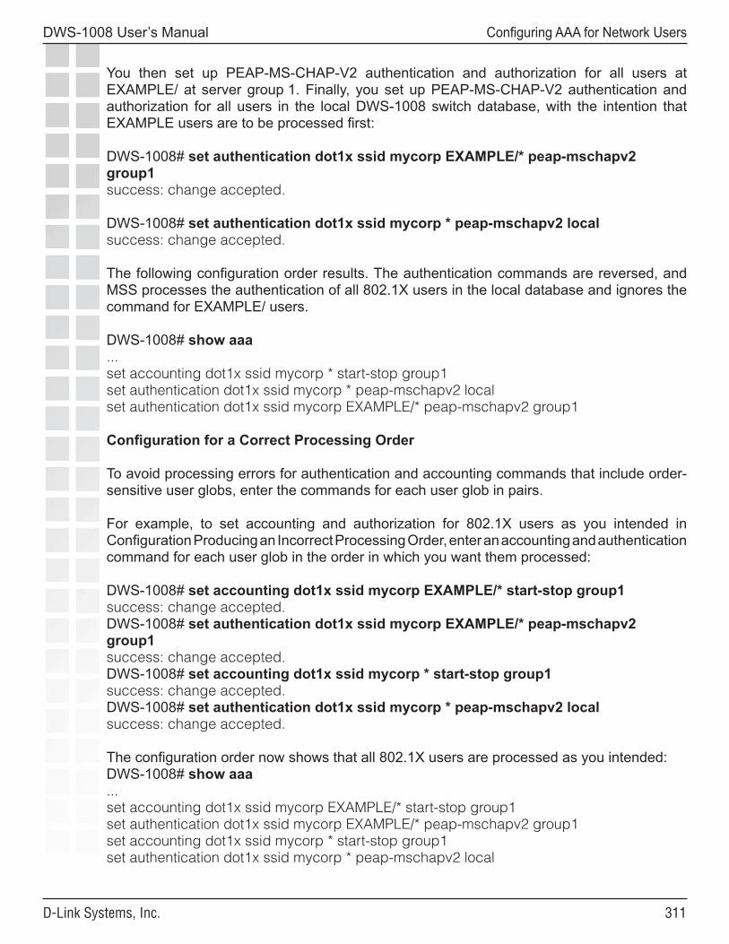
���
DWS-1008 User’s Manual
D-Link Systems, Inc.
Configuring AAA for Network Users
You then set up PEAP-MS-CHAP-V2 authentication and authorization for all users at EXAMPLE/ at server group 1. Finally, you set up PEAP-MS-CHAP-V2 authentication and authorization for all users in the local DWS-1008 switch database, with the intention that EXAMPLE users are to be processed first:
DWS-1008# set authentication dot1x ssid mycorp EXAMPLE/* peap-mschapv2 group1success: change accepted.
DWS-1008# set authentication dot1x ssid mycorp * peap-mschapv2 localsuccess: change accepted.
The following configuration order results. The authentication commands are reversed, and MSS processes the authentication of all 802.1X users in the local database and ignores the command for EXAMPLE/ users.
DWS-1008# show aaa...set accounting dot1x ssid mycorp * start-stop group1set authentication dot1x ssid mycorp * peap-mschapv2 localset authentication dot1x ssid mycorp EXAMPLE/* peap-mschapv2 group1
Configuration for a Correct Processing Order
To avoid processing errors for authentication and accounting commands that include order-sensitive user globs, enter the commands for each user glob in pairs.
For example, to set accounting and authorization for 802.1X users as you intended in Configuration Producing an Incorrect Processing Order, enter an accounting and authentication command for each user glob in the order in which you want them processed:
DWS-1008# set accounting dot1x ssid mycorp EXAMPLE/* start-stop group1success: change accepted.DWS-1008# set authentication dot1x ssid mycorp EXAMPLE/* peap-mschapv2 group1success: change accepted.DWS-1008# set accounting dot1x ssid mycorp * start-stop group1success: change accepted.DWS-1008# set authentication dot1x ssid mycorp * peap-mschapv2 localsuccess: change accepted.
The configuration order now shows that all 802.1X users are processed as you intended:DWS-1008# show aaa...set accounting dot1x ssid mycorp EXAMPLE/* start-stop group1set authentication dot1x ssid mycorp EXAMPLE/* peap-mschapv2 group1set accounting dot1x ssid mycorp * start-stop group1set authentication dot1x ssid mycorp * peap-mschapv2 local
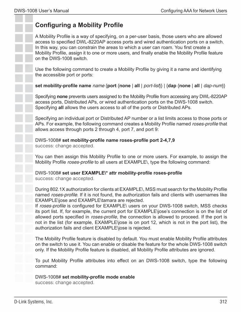
���
DWS-1008 User’s Manual
D-Link Systems, Inc.
Configuring AAA for Network Users
Configuring a Mobility ProfileA Mobility Profile is a way of specifying, on a per-user basis, those users who are allowed access to specified DWL-8220AP access ports and wired authentication ports on a switch. In this way, you can constrain the areas to which a user can roam. You first create a Mobility Profile, assign it to one or more users, and finally enable the Mobility Profile feature on the DWS-1008 switch.
Use the following command to create a Mobility Profile by giving it a name and identifying the accessible port or ports:
set mobility-profile name name {port {none | all | port-list}} | {dap {none | all | dap-num}}
Specifying none prevents users assigned to the Mobility Profile from accessing any DWL-8220AP access ports, Distributed APs, or wired authentication ports on the DWS-1008 switch. Specifying all allows the users access to all of the ports or Distributed APs.
Specifying an individual port or Distributed AP number or a list limits access to those ports or APs. For example, the following command creates a Mobility Profile named roses-profile that allows access through ports 2 through 4, port 7, and port 9:
DWS-1008# set mobility-profile name roses-profile port 2-4,7,9success: change accepted.
You can then assign this Mobility Profile to one or more users. For example, to assign the Mobility Profile roses-profile to all users at EXAMPLE\, type the following command:
DWS-1008# set user EXAMPLE\* attr mobility-profile roses-profilesuccess: change accepted.
During 802.1X authorization for clients at EXAMPLE\, MSS must search for the Mobility Profile named roses-profile. If it is not found, the authorization fails and clients with usernames like EXAMPLE\jose and EXAMPLE\tamara are rejected.If roses-profile is configured for EXAMPLE\ users on your DWS-1008 switch, MSS checks its port list. If, for example, the current port for EXAMPLE\jose’s connection is on the list of allowed ports specified in roses-profile, the connection is allowed to proceed. If the port is not in the list (for example, EXAMPLE\jose is on port 12, which is not in the port list), the authorization fails and client EXAMPLE\jose is rejected.
The Mobility Profile feature is disabled by default. You must enable Mobility Profile attributes on the switch to use it. You can enable or disable the feature for the whole DWS-1008 switch only. If the Mobility Profile feature is disabled, all Mobility Profile attributes are ignored.
To put Mobility Profile attributes into effect on an DWS-1008 switch, type the following command:
DWS-1008# set mobility-profile mode enablesuccess: change accepted.
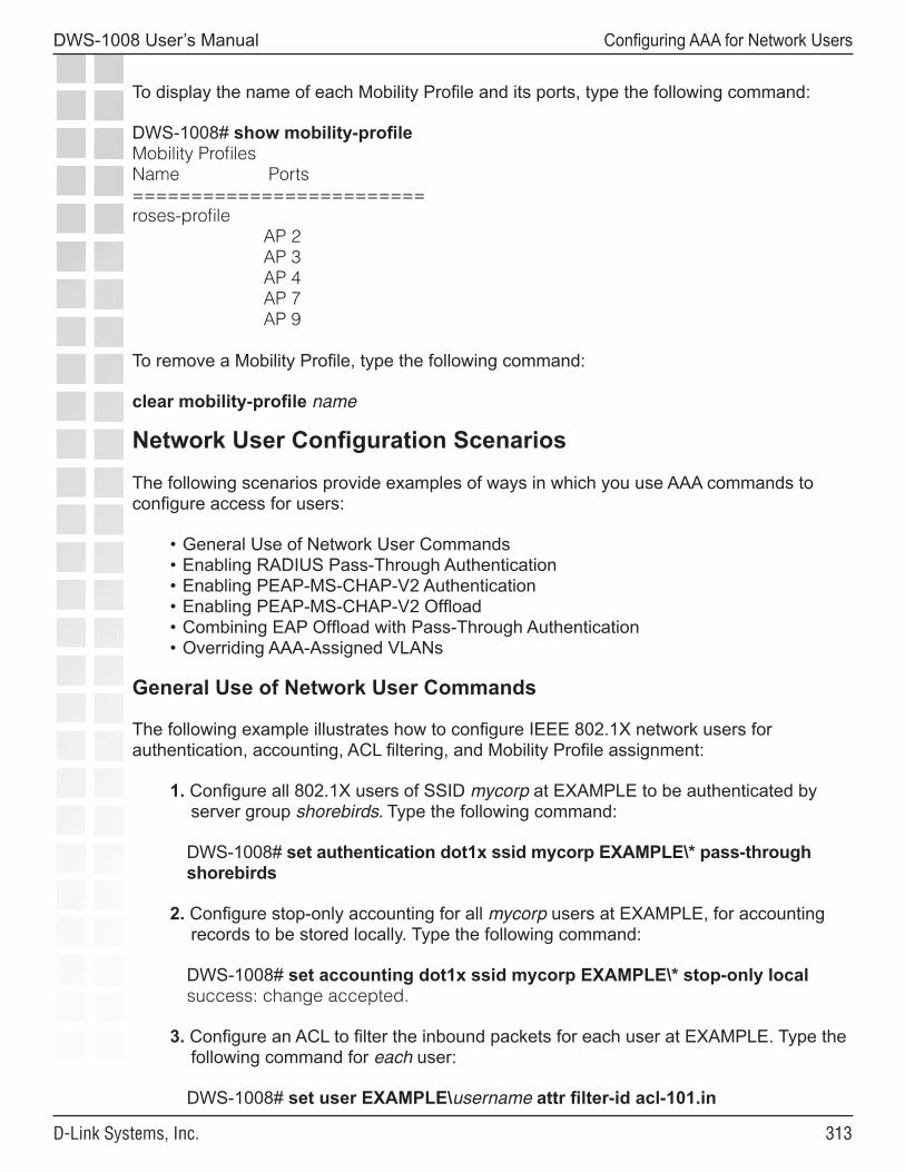
���
DWS-1008 User’s Manual
D-Link Systems, Inc.
Configuring AAA for Network Users
To display the name of each Mobility Profile and its ports, type the following command:
DWS-1008# show mobility-profileMobility ProfilesName Ports=========================roses-profile AP 2 AP 3 AP 4 AP 7 AP 9
To remove a Mobility Profile, type the following command:
clear mobility-profile name
Network User Configuration ScenariosThe following scenarios provide examples of ways in which you use AAA commands to configure access for users:
• General Use of Network User Commands• Enabling RADIUS Pass-Through Authentication• Enabling PEAP-MS-CHAP-V2 Authentication• Enabling PEAP-MS-CHAP-V2 Offload• Combining EAP Offload with Pass-Through Authentication• Overriding AAA-Assigned VLANs
General Use of Network User Commands
The following example illustrates how to configure IEEE 802.1X network users for authentication, accounting, ACL filtering, and Mobility Profile assignment:
1. Configure all 802.1X users of SSID mycorp at EXAMPLE to be authenticated by server group shorebirds. Type the following command:
DWS-1008# set authentication dot1x ssid mycorp EXAMPLE\* pass-through shorebirds
2. Configure stop-only accounting for all mycorp users at EXAMPLE, for accounting records to be stored locally. Type the following command:
DWS-1008# set accounting dot1x ssid mycorp EXAMPLE\* stop-only localsuccess: change accepted.
3. Configure an ACL to filter the inbound packets for each user at EXAMPLE. Type the following command for each user:
DWS-1008# set user EXAMPLE\username attr filter-id acl-101.in
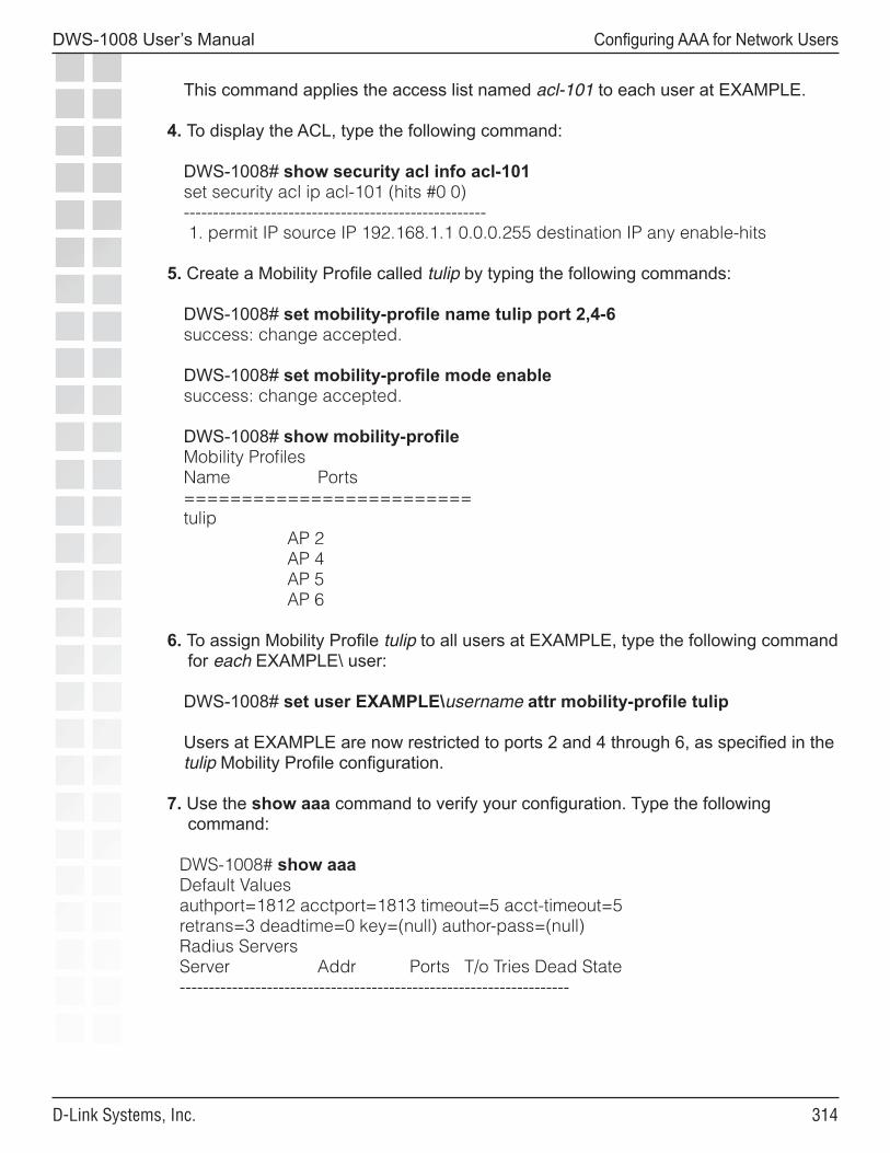
���
DWS-1008 User’s Manual
D-Link Systems, Inc.
Configuring AAA for Network Users
This command applies the access list named acl-101 to each user at EXAMPLE.
4. To display the ACL, type the following command:
DWS-1008# show security acl info acl-101set security acl ip acl-101 (hits #0 0)---------------------------------------------------- 1. permit IP source IP 192.168.1.1 0.0.0.255 destination IP any enable-hits
5. Create a Mobility Profile called tulip by typing the following commands:
DWS-1008# set mobility-profile name tulip port 2,4-6success: change accepted.
DWS-1008# set mobility-profile mode enablesuccess: change accepted.
DWS-1008# show mobility-profileMobility ProfilesName Ports=========================tulip AP 2 AP 4 AP 5 AP 6
6. To assign Mobility Profile tulip to all users at EXAMPLE, type the following command for each EXAMPLE\ user:
DWS-1008# set user EXAMPLE\username attr mobility-profile tulip
Users at EXAMPLE are now restricted to ports 2 and 4 through 6, as specified in the tulip Mobility Profile configuration.
7. Use the show aaa command to verify your configuration. Type the following command:
DWS-1008# show aaaDefault Valuesauthport=1812 acctport=1813 timeout=5 acct-timeout=5retrans=3 deadtime=0 key=(null) author-pass=(null)Radius ServersServer Addr Ports T/o Tries Dead State-------------------------------------------------------------------
���
DWS-1008 User’s Manual
D-Link Systems, Inc.
Configuring AAA for Network Users
set accounting dot1x ssid mycorp EXAMPLE\* stop-only localset authentication dot1x ssid mycorp EXAMPLE\* pass-through shorebirdsuser tech Password = 1315021018 (encrypted)user EXAMPLE/nin filter-id = acl.101.in mobility-profile = tulip
user EXAMPLE/tamara filter-id = acl.101.in mobility-profile = tulip...
8. Save the configuration:
DWS-1008 save configsuccess: configuration saved.
Enabling RADIUS Pass-Through Authentication
The following example illustrates how to enable RADIUS pass-through authentication for all 802.1X network users:
1. Configure the RADIUS server r1 at IP address 10.1.1.1 with the string sunny for the key. Type the following command:
DWS-1008# set radius server r1 address 10.1.1.1 key sunny
2. Configure the server group sg1 with member r1. Type the following command:
DWS-1008# set server group sg1 members r1
3. Enable all 802.1X users of SSID mycorp to authenticate via pass-through to server group sg1. Type the following command:
DWS-1008# set authentication dot1x ssid mycorp * pass-through sg1
4. Save the configuration:
DWS-1008 save configsuccess: configuration saved.
���
DWS-1008 User’s Manual
D-Link Systems, Inc.
Configuring AAA for Network Users
Enabling PEAP-MS-CHAP-V2 Authentication
The following example illustrates how to enable local PEAP-MS-CHAP-V2 authentication for all 802.1X network users. This example includes local usernames, passwords, and membership in a VLAN. This example includes one username and an optional attribute for session-timeout in seconds. Because the switch requires a certificate for authentication, configuration of a self-signed certificate is shown.
1. To set authentication for all 802.1X users of SSID thiscorp, type the following command:
DWS-1008# set authentication dot1x ssid thiscorp * peap-mschapv2 local
2. To add user Natasha to the local database on the switch, type the following command:
DWS-1008# set user Natasha password moon
3. To assign Natasha to a VLAN named red, type the following command:
DWS-1008# set user Natasha attr vlan-name red
4. To assign Natasha a session timeout value of 1200 seconds, type the following command:
DWS-1008# set user Natasha attr session-timeout 1200
5. To generate a public-private key pair and a self-signed EAP certificate, type the following commands:
DWS-1008# crypto generate key eap 1024 key pair generated DWS-1008# crypto generate self-signed eap Country Name: US State Name: CA Locality Name: Campus1 Organizational Name: Example Organizational Unit: IT Common Name: SW33 Email Address: [email protected] Unstructured Name: wiring closet 22
6. Save the configuration: DWS-1008 save config success: configuration saved.
���
DWS-1008 User’s Manual
D-Link Systems, Inc.
Configuring AAA for Network Users
Enabling PEAP-MS-CHAP-V2 Offload
The following example illustrates how to enable PEAP-MS-CHAP-V2 offload. In this example, all EAP processing is offloaded from the RADIUS server, but MS-CHAP-V2 authentication and authorization are done via a RADIUS server. The MS-CHAP-V2 lookup matches users against the user list on a RADIUS server. Because the switch requires a certificate for authentication, a self-signed certificate is shown in this example.
1. Configure the RADIUS server r1 at IP address 10.1.1.1 with the string starry for the key. Type the following command:
DWS-1008# set radius server r1 address 10.1.1.1 key starry
2. Configure the server group sg1 with member r1. Type the following command:
DWS-1008# set server group sg1 members r1
3. Enable all 802.1X users of SSID thiscorp using PEAP-MS-CHAP-V2 to authenticate MS-CHAP-V2 on server group sg1. Type the following command:
DWS-1008# set authentication dot1x ssid thiscorp * peap-mschapv2 sg1
4. To generate a public-private key pair and a self-signed EAP certificate, type the following commands:
DWS-1008# crypto generate key eap 1024 key pair generated
DWS-1008# crypto generate self-signed eap Country Name: US State Name: CA Locality Name: Campus1 Organizational Name: Example Organizational Unit: IT Common Name: SW6 Email Address: [email protected] Unstructured Name: wiring closet 55
5. Save the configuration:
DWS-1008 save config success: configuration saved.
���
DWS-1008 User’s Manual
D-Link Systems, Inc.
Configuring AAA for Network Users
Combining EAP Offload with Pass-Through Authentication
The following example illustrates how to enable PEAP-MS-CHAP-V2 offload for the marketing (mktg) group and RADIUS pass-through authentication for members of engineering. This example assumes that engineering members are using DNS-style naming, such as is used with EAP-TLS. A server certificate is also required. Because the switch requires a certificate for authentication, a self-signed certificate is shown in this example.
1. Configure the RADIUS server r1 at IP address 10.1.1.1 with the string starry for the key. Type the following command:
DWS-1008# set radius server r1 address 10.1.1.1 key starry
2. Configure the server group sg1 with member r1. Type the following command:
DWS-1008# set server group sg1 members r1
3. To authenticate all 802.1X users of SSID bobblehead in the group mktg using PEAP on the switch and MS-CHAP-V2 on server sg1, type the following command:
DWS-1008# set authentication dot1x ssid bobblehead mktg\* peap-mschapv2 sg1
4. To authenticate all 802.1X users of SSID aircorp in @eng.example.com via pass-through to sg1, type the following command:
DWS-1008# set authentication dot1x ssid aircorp *@eng.example.com pass-through sg1
5. To generate a public-private key pair and a self-signed EAP certificate, type the following commands:
DWS-1008# crypto generate key eap 1024 key pair generated
DWS-1008# crypto generate self-signed eap Country Name: US State Name: CA Locality Name: Campus1 Organizational Name: Example Organizational Unit: IT Common Name: SW33 Email Address: [email protected] Unstructured Name: wiring closet south campus
6. Save the configuration: DWS-1008 save config success: configuration saved.
���
DWS-1008 User’s Manual
D-Link Systems, Inc.
Configuring AAA for Network Users
Overriding AAA-Assigned VLANs
The following example shows how to change the VLAN access of wireless users in an organization housed in multiple buildings.
Suppose the wireless users on the faculty of a college English department have offices in building A and are authorized to use that building’s bldga-prof- VLANs. These users also teach classes in building B. Because you do not want to tunnel these users back to building A from building B when they use their wireless laptops in class, you configure the location policy on the switch to redirect them to the bldgb-eng VLAN. You also want to allow writing instructors normally authorized to use any -techcomm VLAN in the college to access the network through the bldgb-eng VLAN when they are in building B.
1. Redirect bldga-prof- VLAN users to the VLAN bldgb-eng:
DWS-1008# set location policy permit vlan bldgb-eng if vlan eq bldga-prof-*
2. Allow writing instructors from -techcomm VLANs to use the bldgb-eng VLAN:
DWS-1008# set location policy permit vlan bldgb-eng if vlan eq *-techcomm
3. Display the configuration:
DWS-1008# show location policy Id Clauses ----------------------------------------------------- 1) permit vlan bldgb-teach if vlan eq bldga-prof-* 2) permit vlan bldgb-eng if vlan eq *-techcomm
4. Save the configuration:
DWS-1008 save config success: configuration saved.
(Footnotes)11. EAP-MD5 does not work with Microsoft wired authentication client
��0
DWS-1008 User’s Manual
D-Link Systems, Inc.
Configuring Communication with RADIUS
Configuring Communication with RADIUSRADIUS OverviewRemote Authentication Dial-In User Service (RADIUS) is a distributed client-server system. RADIUS servers provide a repository for all usernames and passwords, and can manage and store large groups of users.
RADIUS servers store user profiles, which include usernames, passwords, and other AAA attributes. You can use authorization attributes to authorize users for a type of service, for appropriate servers and network segments through VLAN assignments, for packet filtering by access control lists (ACLs), and for other services during a session. You must include RADIUS servers in a server group before you can access them.
Before You BeginTo ensure that you can contact the RADIUS servers you plan to use for authentication, send the ping command to each one to verify connectivity.
ping ip-address
You can then set up communication between the switch and each RADIUS server group.
Configuring RADIUS ServersAn authentication server authenticates each client with access to a switch port before making available any services offered by the switch or the wireless network. The authentication server can reside either in the local database on the switch or on a remote RADIUS server.
When a RADIUS server is used for authentication, you must configure RADIUS server parameters. For each RADIUS server, you must, at a minimum, set the server name, the password (key), and the IP address. You can include any or all of the other optional parameters. You can set some parameters globally for the RADIUS servers.
For RADIUS servers that do not explicitly set their own dead time and timeout timers and transmission attempts, MSS sets the following values by default:
• Dead time - 0 (zero) minutes (The switch does not designate unresponsive RADIUS servers as unavailable.)
• Transmission attempts - 3• Timeout (wait for a server response) - 5 seconds
When MSS sends an authentication or authorization request to a RADIUS server, MSS waits for the amount of the RADIUS timeout for the server to respond. If the server does not respond, MSS retransmits the request. MSS sends the request up to the number of retransmits configured. (The retransmit setting specifies the total number of attempts, including the first attempt.) For example, using the default values, MSS sends a request to a server up to three times, waiting 5 seconds between requests.
���
DWS-1008 User’s Manual
D-Link Systems, Inc.
Configuring Communication with RADIUS
If a server does not respond before the last request attempt times out, MSS holds down further requests to the server, for the duration of the dead time. For example, if you set the dead time to 5 minutes, MSS stops sending requests to the unresponsive server for 5 minutes before reattempting to use the server.
During the holddown, it is as if the dead RADIUS server does not exist. MSS skips over any dead RADIUS servers to the next live server, or on to the next method if no more live servers are available, depending on your configuration. For example, if a RADIUS server group is the primary authentication method and local is the secondary method, MSS fails over to the local method if all RADIUS servers in the server group are unresponsive and have entered the dead time.
For failover authentication or authorization to work promptly, D-Link recommends that you change the dead time to a value other than 0. With the default setting, the dead time is never invoked and MSS does not hold down requests to unresponsive RADIUS servers. Instead, MSS attempts to send each new authentication or authorization request to a server even if the server is thought to be unresponsive. This behavior can cause authentication or authorization failures on clients because MSS does not fail over to the local method soon enough and the clients eventually time out.
Configuring Global RADIUS Defaults
You can change RADIUS values globally and set a global password (key) with the following command. The key string is the shared secret that the switch uses to authenticate itself to the RADIUS server.
set radius {deadtime minutes | key string | retransmit number | timeout seconds}
For example, the following commands set the dead-time timer to 10 minutes and set the password to r8gney for all RADIUS servers in the configuration:
DWS-1008# set radius deadtime 10success: change accepted.
DWS-1008# set radius key r8gneysuccess: change accepted.
To reset global RADIUS server settings to their factory defaults, use the following command:
clear radius {deadtime | key | retransmit | timeout}
For example, the following command resets the dead-time timer to 0 minutes on all RADIUS servers in the configuration:
DWS-1008# clear radius deadtimesuccess: change accepted.
���
DWS-1008 User’s Manual
D-Link Systems, Inc.
Configuring Communication with RADIUS
Setting the System IP Address as the Source Address
By default, RADIUS packets leaving the switch have the source IP address of the outbound interface on the switch. This source address can change when routing conditions change. If you have set a system IP address for the switch, you can use it as a permanent source address for the RADIUS packets sent by the switch.
To set the system IP address as the address of the RADIUS client, type the following command:
DWS-1008# set radius client system-ipsuccess: change accepted.
To remove the switch’s system IP address from use as the source address in RADIUS client requests from the switch to its RADIUS server(s), type the following command:
DWS-1008# clear radius client system-ipsuccess: change accepted.
The command causes the switch to select a source interface address based on information in its routing table as the RADIUS client address.
Configuring Individual RADIUS Servers
You must set up a name and IP address for each RADIUS server. To configure a RADIUS server, use the following command:
set radius server server-name [address ip-address] [key string]
The server name must be unique for this RADIUS server on this switch. The key (password) string is the shared secret that the switch uses to authenticate itself to the RADIUS server. Do not use the same name for a RADIUS server and a RADIUS server group.
For example, the following command names a RADIUS server rs1 with the IP address 192.168.0.2 and the key testing123:
DWS-1008# set radius server rs1 address 192.168.0.2 key testing123success: change accepted.
You can configure multiple RADIUS servers. When you define server names and keys, case is significant. For example:
DWS-1008# set radius server rs1 address 10.6.7.8 key seCret success: change accepted.
DWS-1008# set radius server rs2 address 10.6.7.9 key BigSecretsuccess: change accepted.
���
DWS-1008 User’s Manual
D-Link Systems, Inc.
Configuring Communication with RADIUS
Note: You must provide RADIUS servers with names that are unique. To prevent confusion, D-Link recommends that RADIUS server names differ in ways other than case. For example, avoid naming two servers RS1 and rs1.
You can configure additional parameters with set radius server, such as the UDP ports used for AAA services and the timeout period. You must configure RADIUS servers into server groups before you can access them.
Deleting RADIUS Servers
To remove a RADIUS server from the configuration, use the following command:
clear radius server server-name
Configuring RADIUS Server Groups
A server group is a named group of up to four RADIUS servers. Before you can use a RADIUS server for authentication, you must first create a RADIUS server group and add the RADIUS server to that group. You can also arrange load balancing, so that authentications are spread out among servers in the group. You must declare all members of a server group, in contact order, when you create the group.
Once the group is configured, you can use a server group name as the AAA method with the set authentication and set accounting commands.
Subsequently, you can change the members of a group or configure load balancing. If you add or remove a RADIUS server in a server group, all the RADIUS dead timers for that server group are reset to the global default.Creating Server Groups
To create a server group, you must first configure the RADIUS servers with their addresses and any optional parameters. After configuring RADIUS servers, type the following command:
set server group group-name members server-name1 [server-name2] [server-name3] [server-name4]
For example, to create a server group called shorebirds with the RADIUS servers heron, egret, and sandpiper, type the following commands:
DWS-1008# set radius server egret address 192.168.253.1 key appleDWS-1008# set radius server heron address 192.168.253.2 key pearDWS-1008# set radius server sandpiper address 192.168.253.3 key plumDWS-1008# set server group shorebirds members egret heron sandpiper
In this example, a request to shorebirds results in the RADIUS servers being contacted in the order that they are listed in the server group configuration, first egret, then heron, then sandpiper. You can change the RADIUS servers in server groups at any time.
���
DWS-1008 User’s Manual
D-Link Systems, Inc.
Configuring Communication with RADIUS
Note: Any RADIUS servers that do not respond are marked dead (unavailable) for a period of time. The unresponsive server is skipped over, as though it did not exist, during its dead time. Once the dead time elapses, the server is again a candidate for receiving requests. To change the default dead-time timer, use the set radius or set radius server command.
Ordering Server Groups
You can configure up to four methods for authentication, authorization, and accounting (AAA). AAA methods can be the local database on the switch and/or one or more RADIUS server groups. You set the order in which the switch attempts the AAA methods by the order in which you enter the methods in CLI commands.
In most cases, if the first method results in a pass or fail, the evaluation is final. If the first method does not respond or results in an error, the switch tries the second method and so on.
However, if the local database is the first method in the list, followed by a RADIUS server group, the switch responds to a failed search of the database by sending a request to the following RADIUS server group. This exception is called local override.
Configuring Load Balancing
You can configure the switch to distribute authentication requests across RADIUS servers in a server group, which is called load balancing. Distributing the authentication process across multiple RADIUS servers significantly reduces the load on individual servers while increasing resiliency on a systemwide basis.
When you configure load balancing, the first client’s RADIUS requests are directed to the first server in the group, the second client’s RADIUS requests are directed to the second server in the group, and so on. When the last server in the group is reached, the cycle is repeated.
Note: MSS attempts to send accounting records to one RADIUS server, even if load balancing is configured.
To configure load balancing, use the following command:
set server group group-name load-balance enable
For example, to configure RADIUS servers pelican and seagull as the server group swampbirds with load balancing:
1. Configure the members of a server group by typing the following command:
DWS-1008# set server group swampbirds members pelican seagullsuccess: change accepted.
2. Enable load balancing by typing the following command:
DWS-1008# set server group swampbirds load-balance enablesuccess: change accepted.
���
DWS-1008 User’s Manual
D-Link Systems, Inc.
Configuring Communication with RADIUS
The following command disables load balancing for a server group:
clear server group group-name load-balance
Adding Members to a Server Group
To add RADIUS servers to a server group, type the following command:
set server group group-name members server-name1 [server-name2] [server-name3] [server-name4]]
The keyword members lists the RADIUS servers contained in the named server group. A server group can contain between one and four RADIUS servers. This command accepts any RADIUS servers as the current set of servers. To change the server members, you must reenter all of them.
For example, to add RADIUS server coot to server group shorebirds:
1. Determine the server group by typing the following command:
DWS-1008# show aaaRadius ServersServer Addr Ports T/o Tries Dead State---------------------------------------------------------------------------------------------------sandpiper 192.168.253.3 1812 1813 5 3 0 UPheron 192.168.253.1 1812 1813 5 3 0 UPcoot 192.168.253.4 1812 1813 5 3 0 UPegret 192.168.253.2 1812 1813 5 3 0 UPServer groups shorebirds (load-balanced): sandpiper heron egret
The RADIUS server coot is configured but not part of the server group shorebirds. 2. To add RADIUS server coot as the last server in the server group shorebirds, type the
following command:
DWS-1008# set server group shorebirds members sandpiper heron egret cootsuccess: change accepted.
Deleting a Server Group
To remove a server group, type the following command:
clear server group group-name
���
DWS-1008 User’s Manual
D-Link Systems, Inc.
Configuring Communication with RADIUS
For example, to delete the server group shorebirds, type the following command:
DWS-1008# clear server group shorebirdssuccess: change accepted.
The members of the group remain configured, although no server groups are shown:
DWS-1008# show aaaDefault Valuesauthport=1812 acctport=1813 timeout=5 acct-timeout=5retrans=3 deadtime=0 key=(null) author-pass=(null)Radius ServersServer Addr Ports T/o Tries Dead State-------------------------------------------------------------------------------------------sandpiper 192.168.253.3 1812 1813 5 3 0 UPheron 192.168.253.1 1812 1813 5 3 0 UPcoot 192.168.253.4 1812 1813 5 3 0 UPegret 192.168.253.2 1812 1813 5 3 0 UPServer groups
RADIUS and Server Group Configuration ScenarioThe following example illustrates how to declare four RADIUS servers to an switch and configure them into two load-balancing server groups, swampbirds and shorebirds:
1. Configure RADIUS servers. Type the following commands:
DWS-1008# set radius server pelican address 192.168.253.11 key elmDWS-1008# set radius server seagull address 192.168.243.12 key firDWS-1008# set radius server egret address 192.168.243.15 key pineDWS-1008# set radius server sandpiper address 192.168.253.17 key oak
2. Place two of the RADIUS servers into a server group called swampbirds. Type the following command:
DWS-1008# set server group swampbirds members pelican seagull
3. Enable load balancing for swampbirds. Type the following command:
DWS-1008# set server group swampbirds load-balance enable
4. Place the other RADIUS servers in a server group called shorebirds. Type the following command:
DWS-1008# set server group shorebirds members egret pelican sandpiper
5. Enable load balancing for shorebirds. Type the following command:
DWS-1008# set server group shorebirds load-balance enable
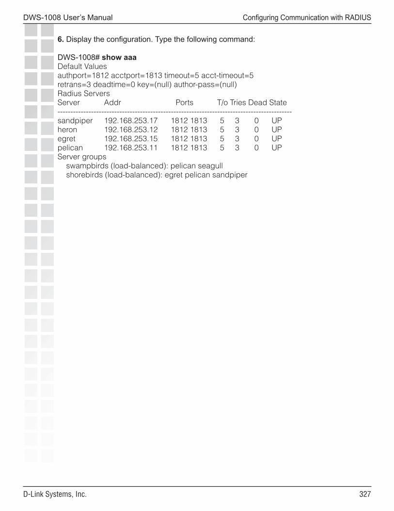
���
DWS-1008 User’s Manual
D-Link Systems, Inc.
Configuring Communication with RADIUS
6. Display the configuration. Type the following command:
DWS-1008# show aaaDefault Valuesauthport=1812 acctport=1813 timeout=5 acct-timeout=5retrans=3 deadtime=0 key=(null) author-pass=(null)Radius ServersServer Addr Ports T/o Tries Dead State-------------------------------------------------------------------------------------------sandpiper 192.168.253.17 1812 1813 5 3 0 UPheron 192.168.253.12 1812 1813 5 3 0 UPegret 192.168.253.15 1812 1813 5 3 0 UPpelican 192.168.253.11 1812 1813 5 3 0 UPServer groups swampbirds (load-balanced): pelican seagull shorebirds (load-balanced): egret pelican sandpiper
���
DWS-1008 User’s Manual
D-Link Systems, Inc.
Managing 802.1X
Managing 802.1XCertain settings for IEEE 802.1X sessions on the DWS-1008 switch are enabled by default. For best results, change the settings only if you are aware of a problem with the switch’s 802.1X performance. For settings that you can reset with a clear command, MSS reverts to the default value.
Caution: 802.1X parameter settings are global for all SSIDs configured on the switch.
Managing 802.1X on Wired Authentication Ports
A wired authentication port is an Ethernet port that has 802.1X authentication enabled for access control. Like wireless users, users that are connected to a switch by Ethernet wire can be authenticated before they can be authorized to use the network. One difference between a wired authenticated user and a wireless authenticated user is that data for wired users is not encrypted after the users are authenticated.
By default, 802.1X authentication is enabled for wired authenticated ports, but you can disable it. You can also set the port to unconditionally authorize, or unconditionally reject, all users.
Enabling and Disabling 802.1X Globally
The following command globally enables or disables 802.1X authentication on all wired authentication ports on a DWS-1008 switch:
set dot1x authcontrol {enable | disable}
The default setting is enable, which permits 802.1X authentication to occur as determined by the set dot1X port-control command for each wired authentication port. The disable setting forces all wired authentication ports to unconditionally authorize all 802.1X authentication attempts by users with an EAP success message.
To reenable 802.1X authentication on wired authentication ports, type the following command:
DWS-1008# set dot1x authcontrol enablesuccess: dot1x authcontrol enabled.
Setting 802.1X Port Control
The following command specifies the way a wired authentication port or group of ports handles user 802.1X authentication attempts:
set dot1x port-control {forceauth | forceunauth | auto} port-list
The default setting is auto, which allows the switch to process 802.1X authentication normally according to the authentication configuration. Alternatively, you can set a wired authentication port or ports to either unconditionally authenticate or unconditionally reject all users.
���
DWS-1008 User’s Manual
D-Link Systems, Inc.
Managing 802.1X
For example, the following command forces port 19 to unconditionally authenticate all 802.1X authentication attempts with an EAP success message:
DWS-1008# set dot1x port-control forceauth 19success: authcontrol for 19 is set to FORCE-AUTH.
Similarly, the following command forces port 12 to unconditionally reject any 802.1X attempts with an EAP failure message:
DWS-1008# set dot1x port-control forceunauth 12success: authcontrol for 12 is set to FORCE-UNAUTH.
The set dot1x port-control command is overridden by the set dot1x authcontrol command. The clear dot1x port-control command returns port control to the default auto value. Type the following command to reset port control for all wired authentication ports:
DWS-1008# clear dot1x port-control success: change accepted.
Managing 802.1X Encryption Keys
By default, the switch sends encryption key information to a wireless supplicant (client) in an Extensible Authentication Protocol over LAN (EAPoL) packet after authentication is successful. You can disable this feature or change the time interval for key transmission.
The secret Wired-Equivalent Privacy protocol (WEP) keys used by MSS on access points for broadcast communication on a VLAN are automatically rotated (rekeyed) every 30 minutes to maintain secure packet transmission. You can disable WEP key rotation for debugging purposes, or change the rotation interval.
Enabling 802.1X Key Transmission
The following command enables or disables the transmission of key information to the supplicant (client) in EAPoL key messages, after authentication:
set dot1x key-tx {enable | disable}
Key transmission is enabled by default.
The switch sends EAPoL key messages after successfully authenticating the supplicant (client) and receiving authorization attributes for the client. If the client is using dynamic WEP, the EAPoL Key messages are sent immediately after authorization.
Type the following command to reenable key transmission:
DWS-1008# set dot1x key-tx enablesuccess: dot1x key transmission enabled.
��0
DWS-1008 User’s Manual
D-Link Systems, Inc.
Managing 802.1X
Configuring 802.1X Key Transmission Time Intervals
The following command sets the number of seconds the switch waits before retransmitting an EAPoL packet of key information:
set dot1x tx-period seconds
The default is 5 seconds. The range for the retransmission interval is from 1 to 65,535 seconds. For example, type the following command to set the retransmission interval to 300 seconds:
DWS-1008# set dot1x tx-period 300success: dot1x tx-period set to 300.
Type the following command to reset the retransmission interval to the 5-second default:
DWS-1008# clear dot1x tx-periodsuccess: change accepted.
Managing WEP Keys
Wired-Equivalent Privacy (WEP) is part of the system security of 802.1X. MSS uses WEP to provide confidentiality to packets as they are sent over the air. WEP operates on the DWL-8220AP access point.
WEP uses a secret key shared between the communicators. WEP rekeying increases the security of the network. New unicast keys are generated every time a client performs 802.1X authentication.
The rekeying process can be performed automatically on a periodic basis. By setting the Session-Timeout RADIUS attribute, you make the reauthentication transparent to the client, who is unaware that reauthentication is occurring. A good value for Session-Timeout is 30 minutes.
WEP broadcast rekeying causes the broadcast and multicast keys for WEP to be rotated every WEP rekey period for each radio to each connected VLAN. The switch generates the new broadcast and multicast keys and pushes the keys to the clients via EAPoL key messages. WEP keys are case-insensitive.
Use the set dot1x wep-rekey and the set dot1x wep-rekey-period commands to enable WEP key rotation and configure the time interval for WEP key rotation. Configuring 802.1X WEP Rekeying
WEP rekeying is enabled by default on the switch. Disable WEP rekeying only if you need to debug your 802.1X network.
���
DWS-1008 User’s Manual
D-Link Systems, Inc.
Managing 802.1X
Use the following command to disable WEP rekeying for broadcast and multicast keys:
DWS-1008# set dot1x wep-rekey disablesuccess: wep rekeying disabled
Note: Reauthentication is not required for using this command. Broadcast and multicast keys are always rotated at the same time, so all members of a given radio and VLAN receive the new keys at the same time.
To reenable WEP rekeying, type the following command:
DWS-1008# set dot1x wep-rekey enablesuccess: wep rekeying enabled
Configuring the Interval for WEP Rekeying
The following command sets the interval for rotating the WEP broadcast and multicast keys:
set dot1x wep-rekey-period seconds
The default is 1800 seconds (30 minutes). You can set the interval from 30 to 1,641,600 seconds (19 days). For example, type the following command to set the WEP-rekey period to 900 seconds:
DWS-1008# set dot1x wep-rekey-period 900success: dot1x wep-rekey-period set to 900
Setting EAP Retransmission Attempts
The following command sets the maximum number of times the switch retransmits an 802.1X-encapsulated EAP request to the supplicant (client) before it times out the authentication session:
set dot1x max-req number-of-retransmissions
The default number of retransmissions is 2. You can specify from 0 to 10 retransmit attempts. For example, type the following command to set the maximum number of retransmission attempts to 3:
DWS-1008# set dot1x max-req 3success: dot1x max request set to 3.
To reset the number of retransmission attempts to the default setting, type the following command:
DWS-1008# clear dot1x max-reqsuccess: change accepted.
���
DWS-1008 User’s Manual
D-Link Systems, Inc.
Managing 802.1X
Note: To support SSIDs that have both 802.1X and static WEP clients, MSS sends a maximum of two ID requests, even if this parameter is set to a higher value. Setting the parameter to a higher value does affect all other types of EAP messages.
Managing 802.1X Client Reauthentication
Reauthentication of 802.1X wireless supplicants (clients) is enabled on the switch by default. By default, the switch waits 3600 seconds (1 hour) between authentication attempts. You can disable reauthentication or change the defaults.
Note: You also can use the RADIUS session-timeout attribute to set the reauthentication timeout for a specific client. In this case, MSS uses the timeout that has the lower value. If the session-timeout is set to fewer seconds than the global reauthentication timeout, MSS uses the session-timeout for the client. However, if the global reauthentication timeout is shorter than the session-timeout, MSS uses the global timeout instead.
Enabling and Disabling 802.1X Reauthentication
The following command enables or disables the reauthentication of supplicants (clients) by the switch:
set dot1x reauth {enable | disable}
Reauthentication is enabled by default.
Type the following command to reenable reauthentication of clients:
DWS-1008# set dot1x reauth enablesuccess: dot1x reauthentication enabled.
Setting the Maximum Number of 802.1X Reauthentication Attempts
The following command sets the number of reauthentication attempts that the switch makes before the supplicant (client) becomes unauthorized:
set dot1x reauth-max number-of-attempts
The default number of reauthentication attempts is 2. You can specify from 1 to 10 attempts. For example, type the following command to set the number of authentication attempts to 8:
DWS-1008# set dot1x reauth-max 8success: dot1x max reauth set to 8.
Type the following command to reset the maximum number of reauthorization attempts to the default:
DWS-1008# clear dot1x reauth-maxsuccess: change accepted.
���
DWS-1008 User’s Manual
D-Link Systems, Inc.
Managing 802.1X
Note: If the number of reauthentications for a wired authentication client is greater than the maximum number of reauthentications allowed, MSS sends an EAP failure packet to the client and removes the client from the network. However, MSS does not remove a wireless client from the network under these circumstances.
Setting the 802.1X Reauthentication Period
The following command configures the number of seconds that the switch waits before attempting reauthentication:
set dot1x reauth-period seconds
The default is 3600 seconds (1 hour). The range is from 60 to 1,641,600 seconds (19 days). This value can be overridden by user authorization parameters.
MSS reauthenticates dynamic WEP clients based on the reauthentication timer. MSS also reauthenticates WPA clients if the clients use the WEP-40 or WEP-104 cipher. For each dynamic WEP client or WPA client using a WEP cipher, the reauthentication timer is set to the lesser of the global setting or the value returned by the AAA server with the rest of the authorization attributes for that client.
For example, type the following command to set the number of seconds to 100 before reauthentication is attempted:
DWS-1008# set dot1x reauth-period 100success: dot1x auth-server timeout set to 100.
Type the following command to reset the default timeout period:
DWS-1008# clear dot1x reauth-periodsuccess: change accepted.
Setting the Bonded Authentication Period
The following command sets the Bonded Auth™ (bonded authentication) period, which is the number of seconds MSS retains session information for an authenticated machine while waiting for the 802.1X client on the machine to start (re)authentication for the user.
Normally, the Bonded Auth period needs to be set only if the network has Bonded Auth clients that use dynamic WEP, or use WEP-40 or WEP-104 encryption with WPA or RSN. These clients can be affected by the 802.1X reauthentication parameter or the RADIUS Session-Timeout parameter.
To set the Bonded Auth period, use the following command:
set dot1x bonded-period seconds
The Bonded Auth period applies only to 802.1X authentication rules that contain the bonded option.
���
DWS-1008 User’s Manual
D-Link Systems, Inc.
Managing 802.1X
To reset the Bonded Auth period to its default value, use the following command:
clear dot1x max-req
Managing Other Timers
By default, the switch waits 60 seconds before responding to a client whose authentication failed, and times out a request to a RADIUS server or an authentication session with a client after 30 seconds. You can modify these defaults.
Setting the 802.1X Quiet Period
The following command configures the number of seconds a switch remains quiet and does not respond to a supplicant (client) after a failed authentication:
set dot1x quiet-period seconds
The default is 60 seconds. The acceptable range is from 0 to 65,535 seconds.
For example, type the following command to set the quiet period to 300 seconds:
DWS-1008# set dot1x quiet-period 300success: dot1x quiet period set to 300.
Type the following command to reset the 802.1X quiet period to the default:
DWS-1008# clear dot1x quiet-periodsuccess: change accepted.
Setting the 802.1X Timeout for an Authorization Server
Use this command to configure the number of seconds before the switch times out a request to a RADIUS authorization server.
set dot1x timeout auth-server seconds
The default is 30 seconds. The range is from 1 to 65,535 seconds.
For example, type the following command to set the authorization server timeout to 60 seconds:
DWS-1008# set dot1x timeout auth-server 60success: dot1x auth-server timeout set to 60.
To reset the authorization server timeout to the default, type the following command:
DWS-1008# clear dot1x timeout auth-serversuccess: change accepted.
���
DWS-1008 User’s Manual
D-Link Systems, Inc.
Managing 802.1X
Setting the 802.1X Timeout for a Client
Use the following command to set the number of seconds before the switch times out an authentication session with a supplicant (client):
set dot1x timeout supplicant seconds
The default is 30 seconds. The range of time is from 1 to 65,535 seconds.
For example, type the following command to set the number of seconds for a timeout to 300:
DWS-1008# set dot1x timeout supplicant 300success: dot1x supplicant timeout set to 300.
Type the following command to reset the timeout period:
DWS-1008# clear dot1x timeout supplicantsuccess: change accepted.
Displaying 802.1X Information
This command displays 802.1X information for clients, statistics, VLANs, and configuration.
show dot1x {clients | stats | config}
• show dot1x clients displays the username, MAC address, VLAN, and state of active 802.1X clients.
• show dot1x config displays a summary of the current configuration.
• show dot1x stats displays global 802.1X statistical information associated with connecting and authenticating.
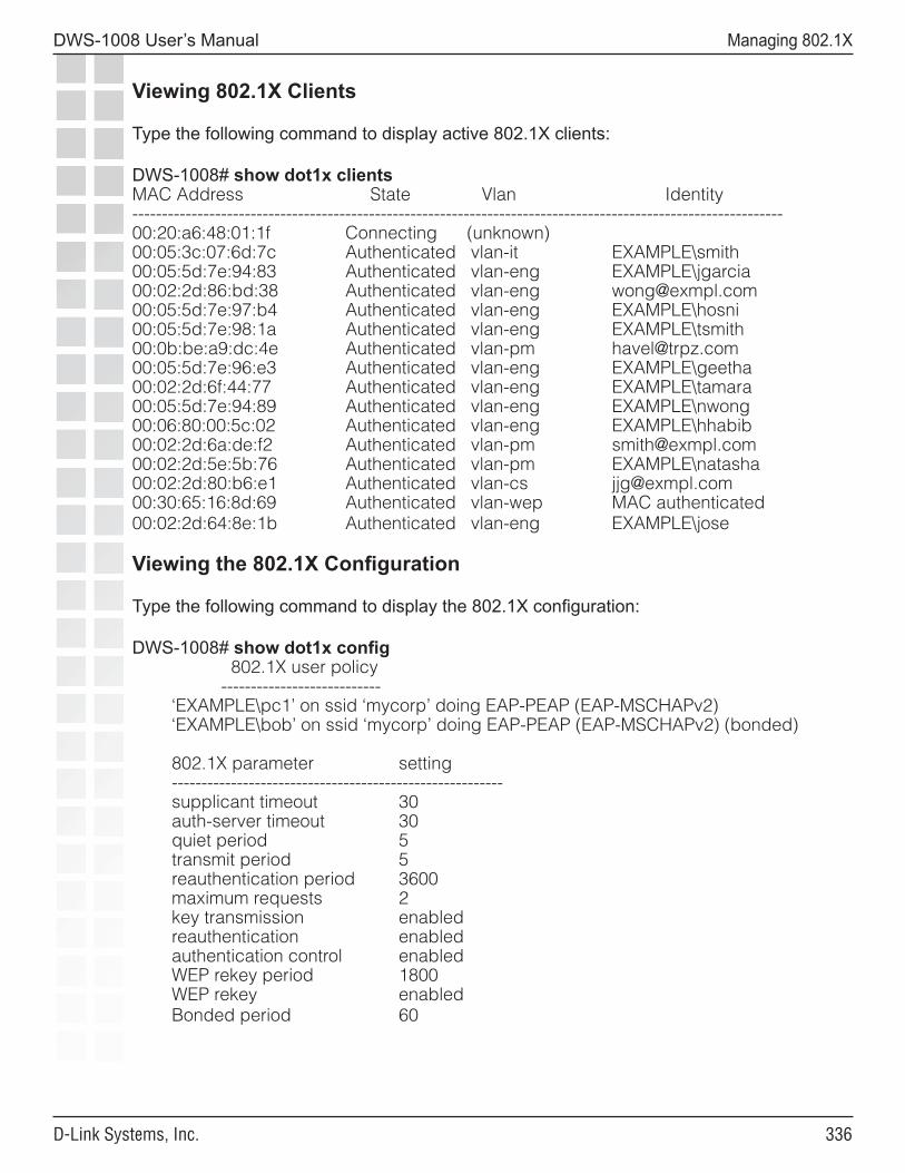
���
DWS-1008 User’s Manual
D-Link Systems, Inc.
Managing 802.1X
Viewing 802.1X Clients
Type the following command to display active 802.1X clients:
DWS-1008# show dot1x clientsMAC Address State Vlan Identity--------------------------------------------------------------------------------------------------------------00:20:a6:48:01:1f Connecting (unknown)00:05:3c:07:6d:7c Authenticated vlan-it EXAMPLE\smith00:05:5d:7e:94:83 Authenticated vlan-eng EXAMPLE\jgarcia00:02:2d:86:bd:38 Authenticated vlan-eng [email protected]:05:5d:7e:97:b4 Authenticated vlan-eng EXAMPLE\hosni00:05:5d:7e:98:1a Authenticated vlan-eng EXAMPLE\tsmith00:0b:be:a9:dc:4e Authenticated vlan-pm [email protected]:05:5d:7e:96:e3 Authenticated vlan-eng EXAMPLE\geetha00:02:2d:6f:44:77 Authenticated vlan-eng EXAMPLE\tamara00:05:5d:7e:94:89 Authenticated vlan-eng EXAMPLE\nwong00:06:80:00:5c:02 Authenticated vlan-eng EXAMPLE\hhabib00:02:2d:6a:de:f2 Authenticated vlan-pm [email protected]:02:2d:5e:5b:76 Authenticated vlan-pm EXAMPLE\natasha00:02:2d:80:b6:e1 Authenticated vlan-cs [email protected]:30:65:16:8d:69 Authenticated vlan-wep MAC authenticated00:02:2d:64:8e:1b Authenticated vlan-eng EXAMPLE\jose
Viewing the 802.1X Configuration
Type the following command to display the 802.1X configuration:
DWS-1008# show dot1x config 802.1X user policy --------------------------- ‘EXAMPLE\pc1’ on ssid ‘mycorp’ doing EAP-PEAP (EAP-MSCHAPv2) ‘EXAMPLE\bob’ on ssid ‘mycorp’ doing EAP-PEAP (EAP-MSCHAPv2) (bonded)
802.1X parameter setting -------------------------------------------------------- supplicant timeout 30 auth-server timeout 30 quiet period 5 transmit period 5 reauthentication period 3600 maximum requests 2 key transmission enabled reauthentication enabled authentication control enabled WEP rekey period 1800 WEP rekey enabled Bonded period 60
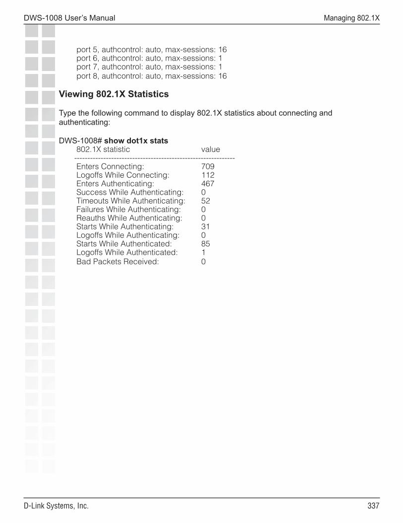
���
DWS-1008 User’s Manual
D-Link Systems, Inc.
Managing 802.1X
port 5, authcontrol: auto, max-sessions: 16 port 6, authcontrol: auto, max-sessions: 1 port 7, authcontrol: auto, max-sessions: 1 port 8, authcontrol: auto, max-sessions: 16 Viewing 802.1X Statistics
Type the following command to display 802.1X statistics about connecting and authenticating:
DWS-1008# show dot1x stats 802.1X statistic value ------------------------------------------------------------- Enters Connecting: 709 Logoffs While Connecting: 112 Enters Authenticating: 467 Success While Authenticating: 0 Timeouts While Authenticating: 52 Failures While Authenticating: 0 Reauths While Authenticating: 0 Starts While Authenticating: 31 Logoffs While Authenticating: 0 Starts While Authenticated: 85 Logoffs While Authenticated: 1 Bad Packets Received: 0
���
DWS-1008 User’s Manual
D-Link Systems, Inc.
Managing Sessions
Managing SessionsAbout the Session ManagerA session is a related set of communication transactions between an authenticated user (client) and the specific station to which the client is bound. Packets are exchanged during a session. A DWS-1008 switch supports the following kinds of sessions:
• Administrative sessions - A network administrator managing the switch
• Network sessions - A network user exchanging traffic with a network through the switch
The session manager manages the sessions for each client, but does not examine the substance of the traffic.
Clearing (ending) a session deauthenticates the administrator or user from the session and disassociates wireless clients.
Displaying and Clearing Administrative SessionsTo display session information and statistics for a user with administrative access to the switch, use the following command:
show sessions {admin | console | telnet [client]}
You can view all administrative sessions, or only the sessions of administrators with access to the switch through a Telnet or SSH connection or the console port. You can also display information about administrative Telnet sessions from remote clients.
To clear administrative sessions, use the following command:
clear sessions {admin | console | telnet [client [session-id]]}
Caution: Clearing administrative sessions might cause your session to be cleared.
Displaying and Clearing All Administrative Sessions
To view information about the sessions of all administrative users, type the following command:
DWS-1008> show sessions adminTty Username Time (s) Type------- -------------------- -------- ----------tty0 3644 Consoletty2 tech 6 Telnettty3 sshadmin 381 SSH
3 admin sessions
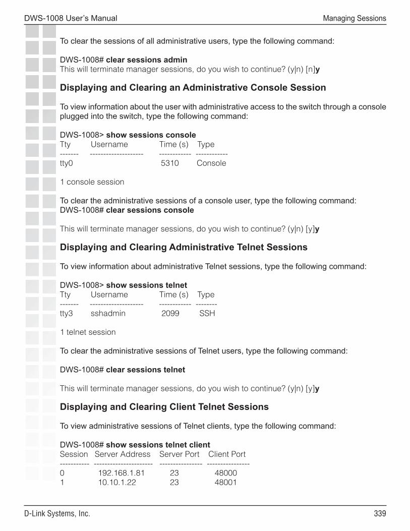
���
DWS-1008 User’s Manual
D-Link Systems, Inc.
Managing Sessions
To clear the sessions of all administrative users, type the following command:
DWS-1008# clear sessions adminThis will terminate manager sessions, do you wish to continue? (y|n) [n]y
Displaying and Clearing an Administrative Console Session
To view information about the user with administrative access to the switch through a console plugged into the switch, type the following command:
DWS-1008> show sessions consoleTty Username Time (s) Type------- -------------------- ------------ ------------tty0 5310 Console
1 console session
To clear the administrative sessions of a console user, type the following command:DWS-1008# clear sessions console
This will terminate manager sessions, do you wish to continue? (y|n) [y]y
Displaying and Clearing Administrative Telnet Sessions
To view information about administrative Telnet sessions, type the following command:
DWS-1008> show sessions telnetTty Username Time (s) Type------- -------------------- ------------ --------tty3 sshadmin 2099 SSH
1 telnet session
To clear the administrative sessions of Telnet users, type the following command:
DWS-1008# clear sessions telnet
This will terminate manager sessions, do you wish to continue? (y|n) [y]y
Displaying and Clearing Client Telnet Sessions
To view administrative sessions of Telnet clients, type the following command:
DWS-1008# show sessions telnet clientSession Server Address Server Port Client Port----------- ---------------------- ---------------- ----------------0 192.168.1.81 23 480001 10.10.1.22 23 48001
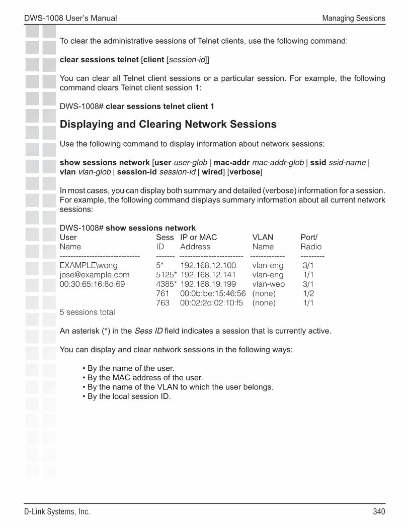
��0
DWS-1008 User’s Manual
D-Link Systems, Inc.
Managing Sessions
To clear the administrative sessions of Telnet clients, use the following command:
clear sessions telnet [client [session-id]]
You can clear all Telnet client sessions or a particular session. For example, the following command clears Telnet client session 1:
DWS-1008# clear sessions telnet client 1
Displaying and Clearing Network Sessions
Use the following command to display information about network sessions:
show sessions network [user user-glob | mac-addr mac-addr-glob | ssid ssid-name | vlan vlan-glob | session-id session-id | wired] [verbose]
In most cases, you can display both summary and detailed (verbose) information for a session. For example, the following command displays summary information about all current network sessions:
DWS-1008# show sessions networkUser Sess IP or MAC VLAN Port/Name ID Address Name Radio------------------------------ ------- ------------------------ ------------- ---------EXAMPLE\wong 5* 192.168.12.100 vlan-eng 3/[email protected] 5125* 192.168.12.141 vlan-eng 1/100:30:65:16:8d:69 4385* 192.168.19.199 vlan-wep 3/1 761 00:0b:be:15:46:56 (none) 1/2 763 00:02:2d:02:10:f5 (none) 1/15 sessions total
An asterisk (*) in the Sess ID field indicates a session that is currently active.
You can display and clear network sessions in the following ways:
• By the name of the user. • By the MAC address of the user. • By the name of the VLAN to which the user belongs. • By the local session ID.
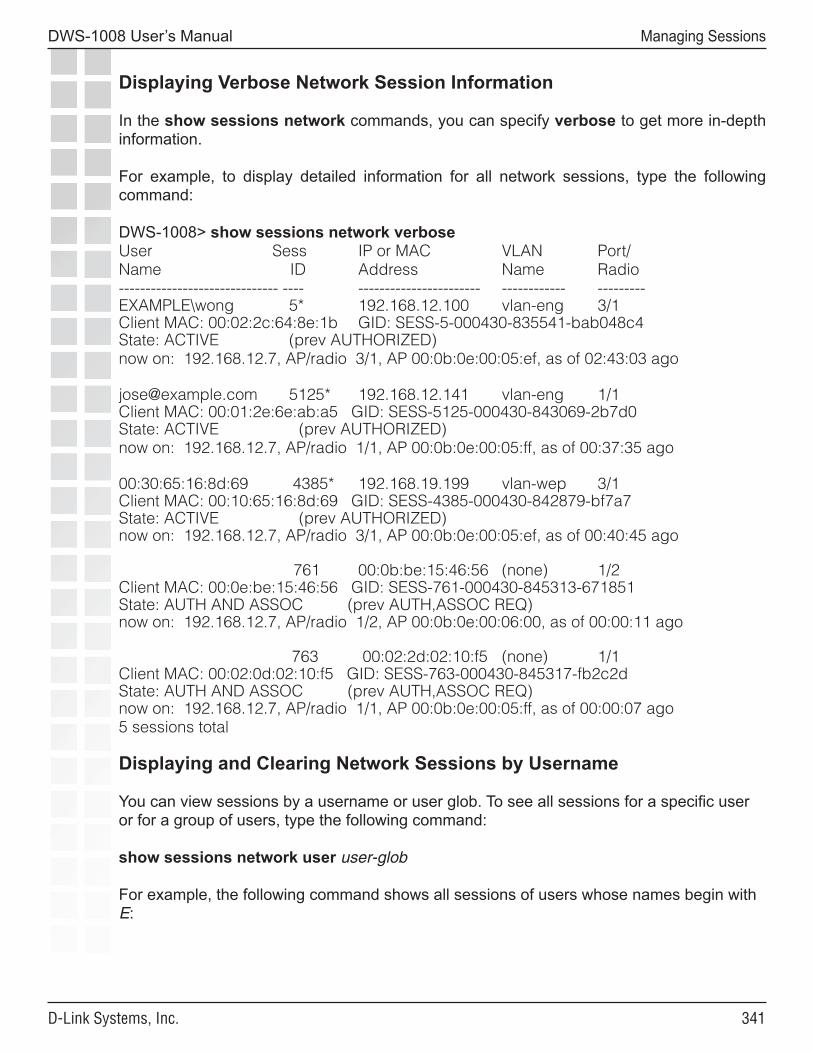
���
DWS-1008 User’s Manual
D-Link Systems, Inc.
Managing Sessions
Displaying Verbose Network Session Information
In the show sessions network commands, you can specify verbose to get more in-depth information.
For example, to display detailed information for all network sessions, type the following command:
DWS-1008> show sessions network verboseUser Sess IP or MAC VLAN Port/Name ID Address Name Radio------------------------------ ---- ----------------------- ------------ ---------EXAMPLE\wong 5* 192.168.12.100 vlan-eng 3/1Client MAC: 00:02:2c:64:8e:1b GID: SESS-5-000430-835541-bab048c4State: ACTIVE (prev AUTHORIZED)now on: 192.168.12.7, AP/radio 3/1, AP 00:0b:0e:00:05:ef, as of 02:43:03 ago
[email protected] 5125* 192.168.12.141 vlan-eng 1/1Client MAC: 00:01:2e:6e:ab:a5 GID: SESS-5125-000430-843069-2b7d0State: ACTIVE (prev AUTHORIZED)now on: 192.168.12.7, AP/radio 1/1, AP 00:0b:0e:00:05:ff, as of 00:37:35 ago
00:30:65:16:8d:69 4385* 192.168.19.199 vlan-wep 3/1Client MAC: 00:10:65:16:8d:69 GID: SESS-4385-000430-842879-bf7a7State: ACTIVE (prev AUTHORIZED)now on: 192.168.12.7, AP/radio 3/1, AP 00:0b:0e:00:05:ef, as of 00:40:45 ago
761 00:0b:be:15:46:56 (none) 1/2Client MAC: 00:0e:be:15:46:56 GID: SESS-761-000430-845313-671851State: AUTH AND ASSOC (prev AUTH,ASSOC REQ)now on: 192.168.12.7, AP/radio 1/2, AP 00:0b:0e:00:06:00, as of 00:00:11 ago
763 00:02:2d:02:10:f5 (none) 1/1Client MAC: 00:02:0d:02:10:f5 GID: SESS-763-000430-845317-fb2c2dState: AUTH AND ASSOC (prev AUTH,ASSOC REQ)now on: 192.168.12.7, AP/radio 1/1, AP 00:0b:0e:00:05:ff, as of 00:00:07 ago5 sessions total
Displaying and Clearing Network Sessions by Username
You can view sessions by a username or user glob. To see all sessions for a specific user or for a group of users, type the following command:
show sessions network user user-glob
For example, the following command shows all sessions of users whose names begin with E:
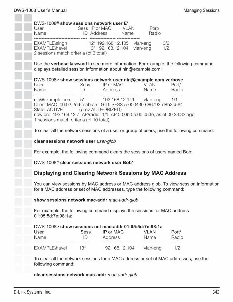
���
DWS-1008 User’s Manual
D-Link Systems, Inc.
Managing Sessions
DWS-1008# show sessions network user E*User Sess IP or MAC VLAN Port/Name ID Address Name Radio------------------------------ ---- ----------------- --------------- EXAMPLE\singh 12* 192.168.12.185 vlan-eng 3/2EXAMPLE\havel 13* 192.168.12.104 vlan-eng 1/22 sessions match criteria (of 3 total)
Use the verbose keyword to see more information. For example, the following command displays detailed session information about [email protected]:
DWS-1008> show sessions network user [email protected] verboseUser Sess IP or MAC VLAN Port/Name ID Address Name Radio-------------------------- ------- ---------------------- ------------ [email protected] 5* 192.168.12.141 vlan-eng 1/1Client MAC: 00:02:2d:6e:ab:a5 GID: SESS-5-000430-686792-d8b3c564State: ACTIVE (prev AUTHORIZED)now on: 192.168.12.7, AP/radio 1/1, AP 00:0b:0e:00:05:fe, as of 00:23:32 ago1 sessions match criteria (of 10 total)
To clear all the network sessions of a user or group of users, use the following command:
clear sessions network user user-glob
For example, the following command clears the sessions of users named Bob:
DWS-1008# clear sessions network user Bob*
Displaying and Clearing Network Sessions by MAC Address
You can view sessions by MAC address or MAC address glob. To view session information for a MAC address or set of MAC addresses, type the following command:
show sessions network mac-addr mac-addr-glob
For example, the following command displays the sessions for MAC address 01:05:5d:7e:98:1a:
DWS-1008> show sessions net mac-addr 01:05:5d:7e:98:1aUser Sess IP or MAC VLAN Port/Name ID Address Name Radio--------------------------- ------- --------------------- ------------ ---------EXAMPLE\havel 13* 192.168.12.104 vlan-eng 1/2
To clear all the network sessions for a MAC address or set of MAC addresses, use the following command:
clear sessions network mac-addr mac-addr-glob
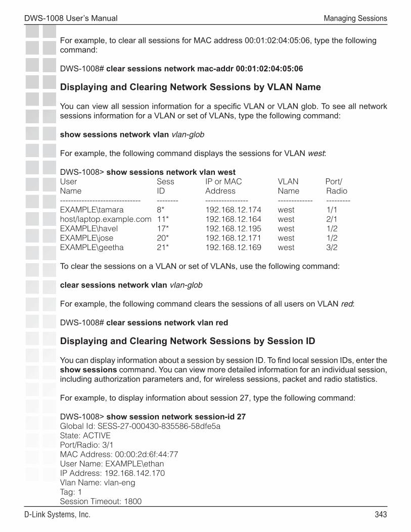
���
DWS-1008 User’s Manual
D-Link Systems, Inc.
Managing Sessions
For example, to clear all sessions for MAC address 00:01:02:04:05:06, type the following command:
DWS-1008# clear sessions network mac-addr 00:01:02:04:05:06
Displaying and Clearing Network Sessions by VLAN Name
You can view all session information for a specific VLAN or VLAN glob. To see all network sessions information for a VLAN or set of VLANs, type the following command:
show sessions network vlan vlan-glob
For example, the following command displays the sessions for VLAN west:
DWS-1008> show sessions network vlan westUser Sess IP or MAC VLAN Port/Name ID Address Name Radio------------------------------ -------- ---------------- ------------- ---------EXAMPLE\tamara 8* 192.168.12.174 west 1/1host/laptop.example.com 11* 192.168.12.164 west 2/1EXAMPLE\havel 17* 192.168.12.195 west 1/2EXAMPLE\jose 20* 192.168.12.171 west 1/2EXAMPLE\geetha 21* 192.168.12.169 west 3/2
To clear the sessions on a VLAN or set of VLANs, use the following command:
clear sessions network vlan vlan-glob
For example, the following command clears the sessions of all users on VLAN red:
DWS-1008# clear sessions network vlan red
Displaying and Clearing Network Sessions by Session ID
You can display information about a session by session ID. To find local session IDs, enter the show sessions command. You can view more detailed information for an individual session, including authorization parameters and, for wireless sessions, packet and radio statistics.
For example, to display information about session 27, type the following command:
DWS-1008> show session network session-id 27Global Id: SESS-27-000430-835586-58dfe5aState: ACTIVEPort/Radio: 3/1MAC Address: 00:00:2d:6f:44:77User Name: EXAMPLE\ethanIP Address: 192.168.142.170Vlan Name: vlan-engTag: 1Session Timeout: 1800
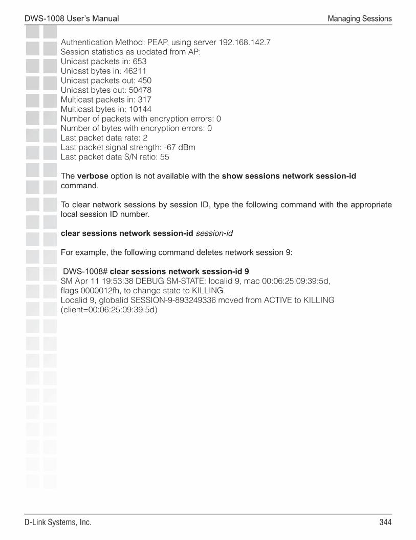
���
DWS-1008 User’s Manual
D-Link Systems, Inc.
Managing Sessions
Authentication Method: PEAP, using server 192.168.142.7Session statistics as updated from AP:Unicast packets in: 653Unicast bytes in: 46211Unicast packets out: 450Unicast bytes out: 50478Multicast packets in: 317Multicast bytes in: 10144Number of packets with encryption errors: 0Number of bytes with encryption errors: 0Last packet data rate: 2Last packet signal strength: -67 dBmLast packet data S/N ratio: 55
The verbose option is not available with the show sessions network session-id command.
To clear network sessions by session ID, type the following command with the appropriate local session ID number.
clear sessions network session-id session-id
For example, the following command deletes network session 9:
DWS-1008# clear sessions network session-id 9SM Apr 11 19:53:38 DEBUG SM-STATE: localid 9, mac 00:06:25:09:39:5d, flags 0000012fh, to change state to KILLINGLocalid 9, globalid SESSION-9-893249336 moved from ACTIVE to KILLING (client=00:06:25:09:39:5d)

���
DWS-1008 User’s Manual
D-Link Systems, Inc.
Rogue Detection and Countermeasures
Rogue Detection and Countermeasures
AP radios automatically scan the RF spectrum for other devices transmitting in the same spectrum. The RF scans discover third-party transmitters in addition to other D-Link radios. MSS considers the non-D-Link transmitters to be devices of interest, which are potential rogues.
You can display information about the devices of interest. To identify friendly devices, such as non-D-Link access points in your network or neighbor’s network, you can add them to the known devices list. You also can enable countermeasures to prevent clients from using the devices that truly are rogues.
About Rogues and RF Detection
RF detection detects all the IEEE 802.11 devices and can single out the unauthorized rogue access points.
Rogue Access Points and Clients
A rogue access point is an access point that is not authorized to operate in a network. Rogue access points and their clients undermine the security of an enterprise network by potentially allowing unchallenged access to the network by any wireless user or client in the physical vicinity. Rogue access points and users can also interfere with the operation of your enterprise network.
Rogue Classification
When MSS detects a third-party wireless device that is not allowed on the network, MSS classifies the device as one of the following:
• Rogue - The device is in the D-Link network but does not belong there.
• Interfering device - The device is not part of the D-Link network but also is not a rogue. No client connected to the device has been detected communicating with any network entity listed in the forwarding database (FDB) of any switch. Although the interfering device is not connected to your network, the device might be causing RF interference with AP radios.
When you enable countermeasures, you can specify whether to issue them against rogues and interfering devices, or against rogues only. For example, if you do not want to issue countermeasures against your neighbor’s wireless devices, you can select to issue countermeasures against rogues only. RF Auto-Tuning can automatically change AP radio channels to work around interfering devices without attacking those devices.
���
DWS-1008 User’s Manual
D-Link Systems, Inc.
Rogue Detection and Countermeasures
Rogue Detection Lists
Rogue detection lists specify the third-party devices and SSIDs that MSS allows on the network, and the devices MSS classifies as rogues. You can configure the following rogue detection lists:
• Permitted SSID list - A list of SSIDs allowed on the network. MSS generates a message if an SSID that is not on the list is detected.
• Permitted vendor list - A list of the wireless networking equipment vendors whose equipment is allowed on the network. The vendor of a piece of equipment is identified by the Organizationally Unique Identifier (OUI), which is the first three bytes of the equipment’s MAC address. MSS generates a message if an AP or wireless client with an OUI that is not on the list is detected.
• Client black list - A list of MAC addresses of wireless clients who are not allowed on the network. MSS prevents clients on the list from accessing the network through a switch. If the client is placed on the black list dynamically by MSS due to an association, reassociation or disassociation flood, MSS generates a log message.
• Ignore list - A list of third-party devices that you want to exempt from rogue detection. MSS does not count devices on the ignore list as rogues or interfering devices, and does not issue countermeasures against them.
An empty permitted SSID list or permitted vendor list implicitly allows all SSIDs or vendors. However, when you add an entry to the SSID or vendor list, all SSIDs or vendors that are not in the list are implicitly disallowed. An empty client black list implicitly allows all clients, and an empty ignore list implicitly considers all third-party wireless devices to be potential rogues.
All the lists except the black list require manual configuration. You can configure entries in the black list and MSS also can place a client in the black list due to an association, reassociation or disassociation flood from the client.
The rogue classification algorithm examines each of these lists when determining whether a device is a rogue. The figure below shows how the rogue detection algorithm uses the lists.
RF Detection Scans
All radios continually scan for other RF transmitters. Radios perform passive scans and active scans:
• Passive scans - The radio listens for beacons and probe responses.
• Active scans - The radio sends probe any requests (probe requests with a null SSID name) to solicit probe responses from other access points.
Passive scans are always enabled and cannot be disabled. Active scans are enabled by default but can be disabled on a radio-profile basis.
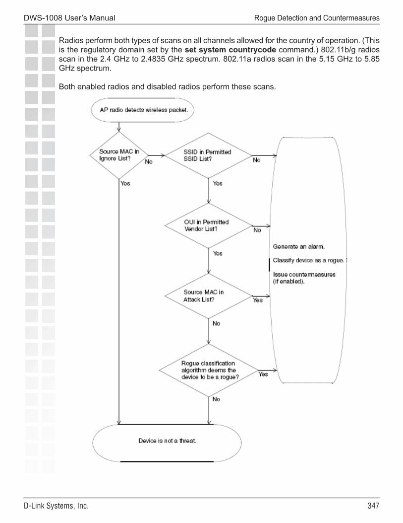
���
DWS-1008 User’s Manual
D-Link Systems, Inc.
Rogue Detection and Countermeasures
Radios perform both types of scans on all channels allowed for the country of operation. (This is the regulatory domain set by the set system countrycode command.) 802.11b/g radios scan in the 2.4 GHz to 2.4835 GHz spectrum. 802.11a radios scan in the 5.15 GHz to 5.85 GHz spectrum.
Both enabled radios and disabled radios perform these scans.
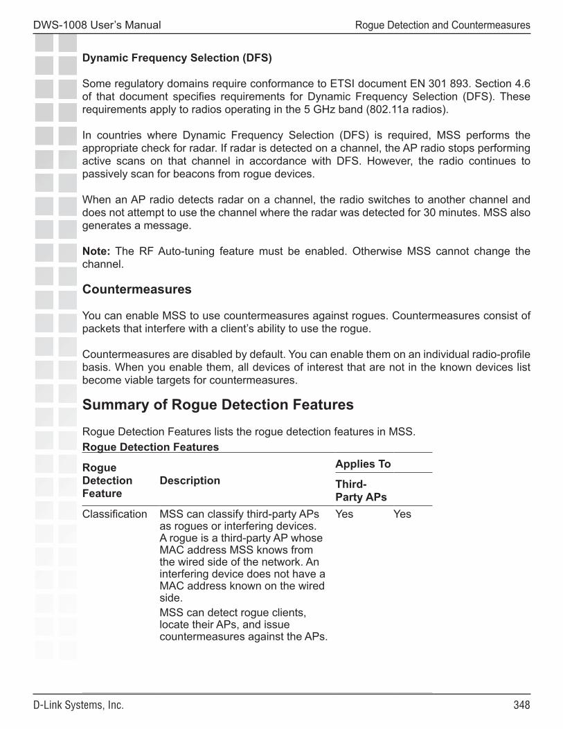
���
DWS-1008 User’s Manual
D-Link Systems, Inc.
Rogue Detection and Countermeasures
Dynamic Frequency Selection (DFS)
Some regulatory domains require conformance to ETSI document EN 301 893. Section 4.6 of that document specifies requirements for Dynamic Frequency Selection (DFS). These requirements apply to radios operating in the 5 GHz band (802.11a radios).
In countries where Dynamic Frequency Selection (DFS) is required, MSS performs the appropriate check for radar. If radar is detected on a channel, the AP radio stops performing active scans on that channel in accordance with DFS. However, the radio continues to passively scan for beacons from rogue devices.
When an AP radio detects radar on a channel, the radio switches to another channel and does not attempt to use the channel where the radar was detected for 30 minutes. MSS also generates a message.
Note: The RF Auto-tuning feature must be enabled. Otherwise MSS cannot change the channel.
Countermeasures
You can enable MSS to use countermeasures against rogues. Countermeasures consist of packets that interfere with a client’s ability to use the rogue.
Countermeasures are disabled by default. You can enable them on an individual radio-profile basis. When you enable them, all devices of interest that are not in the known devices list become viable targets for countermeasures.
Summary of Rogue Detection Features
Rogue Detection Features lists the rogue detection features in MSS. Rogue Detection Features
Rogue Detection Feature
DescriptionApplies To
Third-Party APs
Classification MSS can classify third-party APs as rogues or interfering devices. A rogue is a third-party AP whose MAC address MSS knows from the wired side of the network. An interfering device does not have a MAC address known on the wired side.MSS can detect rogue clients, locate their APs, and issue countermeasures against the APs.
Yes Yes
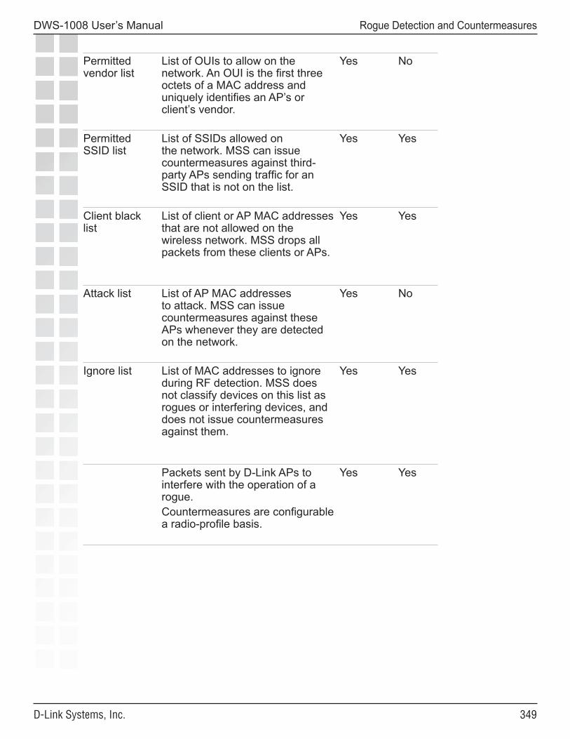
���
DWS-1008 User’s Manual
D-Link Systems, Inc.
Rogue Detection and Countermeasures
Permitted vendor list
List of OUIs to allow on the network. An OUI is the first three octets of a MAC address and uniquely identifies an AP’s or client’s vendor.
Yes No
Permitted SSID list
List of SSIDs allowed on the network. MSS can issue countermeasures against third-party APs sending traffic for an SSID that is not on the list.
Yes Yes
Client black list
List of client or AP MAC addresses that are not allowed on the wireless network. MSS drops all packets from these clients or APs.
Yes Yes
Attack list List of AP MAC addresses to attack. MSS can issue countermeasures against these APs whenever they are detected on the network.
Yes No
Ignore list List of MAC addresses to ignore during RF detection. MSS does not classify devices on this list as rogues or interfering devices, and does not issue countermeasures against them.
Yes Yes
Packets sent by D-Link APs to interfere with the operation of a rogue. Countermeasures are configurable a radio-profile basis.
Yes Yes
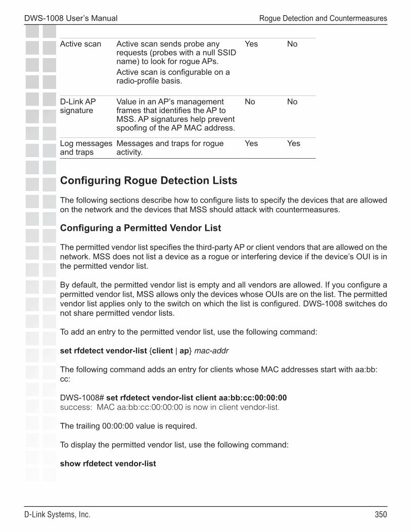
��0
DWS-1008 User’s Manual
D-Link Systems, Inc.
Rogue Detection and Countermeasures
Active scan Active scan sends probe any requests (probes with a null SSID name) to look for rogue APs.Active scan is configurable on a radio-profile basis.
Yes No
D-Link AP signature
Value in an AP’s management frames that identifies the AP to MSS. AP signatures help prevent spoofing of the AP MAC address.
No No
Log messages and traps
Messages and traps for rogue activity.
Yes Yes
Configuring Rogue Detection Lists
The following sections describe how to configure lists to specify the devices that are allowed on the network and the devices that MSS should attack with countermeasures.
Configuring a Permitted Vendor List
The permitted vendor list specifies the third-party AP or client vendors that are allowed on the network. MSS does not list a device as a rogue or interfering device if the device’s OUI is in the permitted vendor list.
By default, the permitted vendor list is empty and all vendors are allowed. If you configure a permitted vendor list, MSS allows only the devices whose OUIs are on the list. The permitted vendor list applies only to the switch on which the list is configured. DWS-1008 switches do not share permitted vendor lists.
To add an entry to the permitted vendor list, use the following command:
set rfdetect vendor-list {client | ap} mac-addr
The following command adds an entry for clients whose MAC addresses start with aa:bb:cc:
DWS-1008# set rfdetect vendor-list client aa:bb:cc:00:00:00success: MAC aa:bb:cc:00:00:00 is now in client vendor-list.
The trailing 00:00:00 value is required.
To display the permitted vendor list, use the following command:
show rfdetect vendor-list
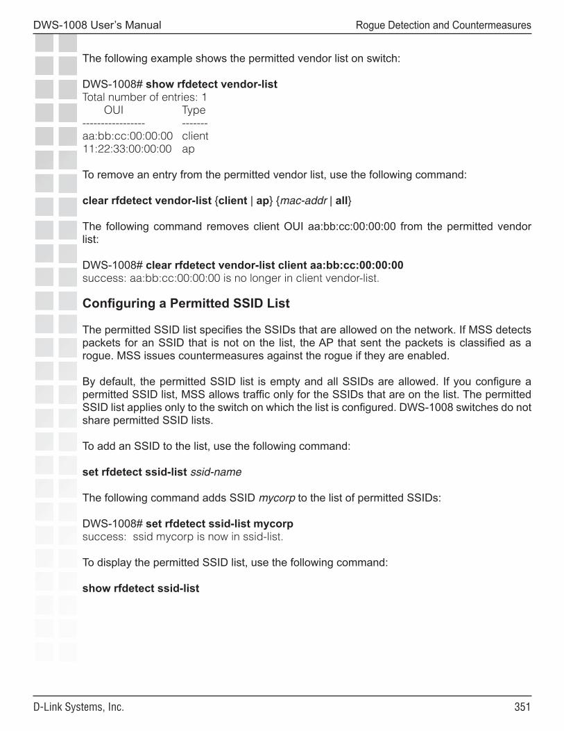
���
DWS-1008 User’s Manual
D-Link Systems, Inc.
Rogue Detection and Countermeasures
The following example shows the permitted vendor list on switch:
DWS-1008# show rfdetect vendor-listTotal number of entries: 1 OUI Type----------------- -------aa:bb:cc:00:00:00 client11:22:33:00:00:00 ap
To remove an entry from the permitted vendor list, use the following command:
clear rfdetect vendor-list {client | ap} {mac-addr | all}
The following command removes client OUI aa:bb:cc:00:00:00 from the permitted vendor list:
DWS-1008# clear rfdetect vendor-list client aa:bb:cc:00:00:00success: aa:bb:cc:00:00:00 is no longer in client vendor-list.
Configuring a Permitted SSID List
The permitted SSID list specifies the SSIDs that are allowed on the network. If MSS detects packets for an SSID that is not on the list, the AP that sent the packets is classified as a rogue. MSS issues countermeasures against the rogue if they are enabled.
By default, the permitted SSID list is empty and all SSIDs are allowed. If you configure a permitted SSID list, MSS allows traffic only for the SSIDs that are on the list. The permitted SSID list applies only to the switch on which the list is configured. DWS-1008 switches do not share permitted SSID lists.
To add an SSID to the list, use the following command:
set rfdetect ssid-list ssid-name
The following command adds SSID mycorp to the list of permitted SSIDs:
DWS-1008# set rfdetect ssid-list mycorpsuccess: ssid mycorp is now in ssid-list.
To display the permitted SSID list, use the following command:
show rfdetect ssid-list
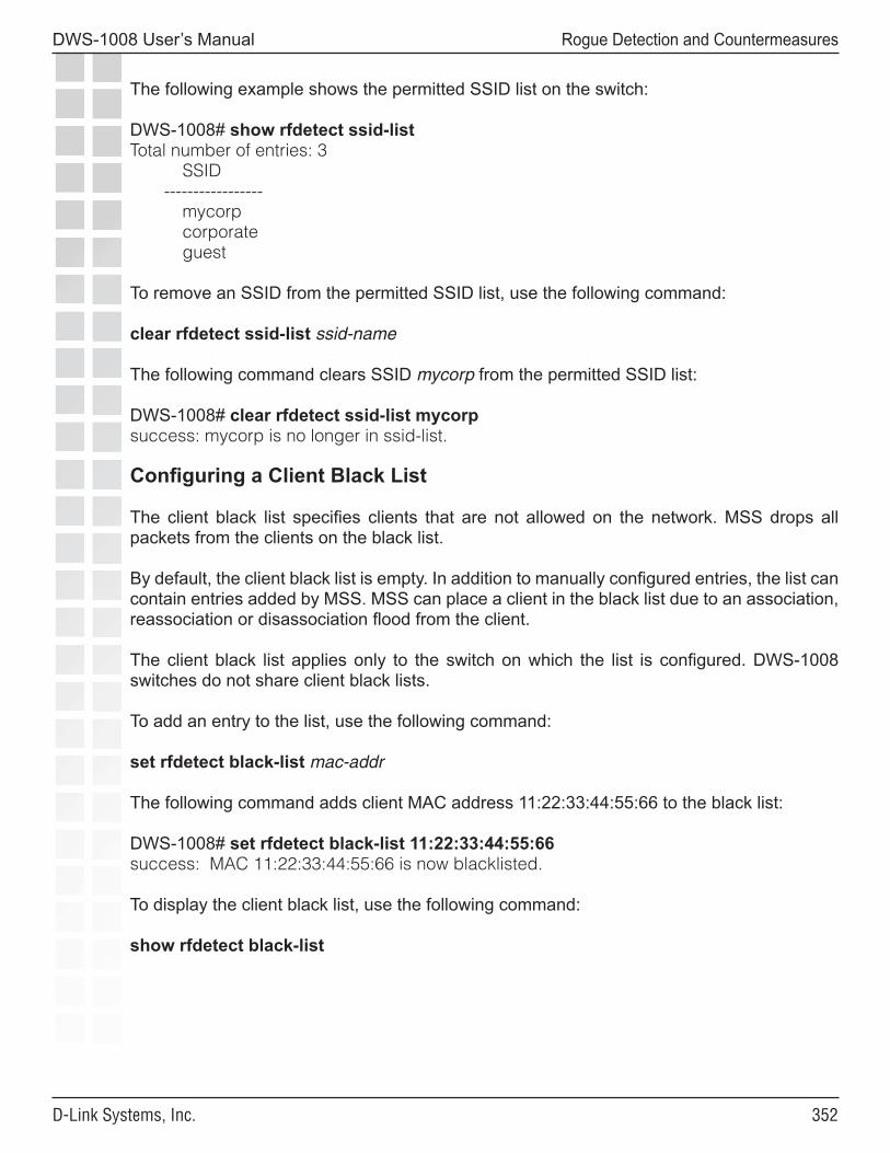
���
DWS-1008 User’s Manual
D-Link Systems, Inc.
Rogue Detection and Countermeasures
The following example shows the permitted SSID list on the switch:
DWS-1008# show rfdetect ssid-listTotal number of entries: 3 SSID ----------------- mycorp corporate guest
To remove an SSID from the permitted SSID list, use the following command:
clear rfdetect ssid-list ssid-name
The following command clears SSID mycorp from the permitted SSID list:
DWS-1008# clear rfdetect ssid-list mycorpsuccess: mycorp is no longer in ssid-list.
Configuring a Client Black List
The client black list specifies clients that are not allowed on the network. MSS drops all packets from the clients on the black list.
By default, the client black list is empty. In addition to manually configured entries, the list can contain entries added by MSS. MSS can place a client in the black list due to an association, reassociation or disassociation flood from the client.
The client black list applies only to the switch on which the list is configured. DWS-1008 switches do not share client black lists.
To add an entry to the list, use the following command:
set rfdetect black-list mac-addr
The following command adds client MAC address 11:22:33:44:55:66 to the black list:
DWS-1008# set rfdetect black-list 11:22:33:44:55:66success: MAC 11:22:33:44:55:66 is now blacklisted.
To display the client black list, use the following command:
show rfdetect black-list
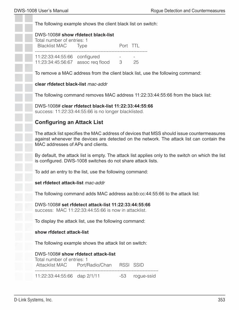
���
DWS-1008 User’s Manual
D-Link Systems, Inc.
Rogue Detection and Countermeasures
The following example shows the client black list on switch:
DWS-1008# show rfdetect black-listTotal number of entries: 1 Blacklist MAC Type Port TTL------------------------------------------------------------------------11:22:33:44:55:66 configured - -11:23:34:45:56:67 assoc req flood 3 25
To remove a MAC address from the client black list, use the following command:
clear rfdetect black-list mac-addr
The following command removes MAC address 11:22:33:44:55:66 from the black list:
DWS-1008# clear rfdetect black-list 11:22:33:44:55:66success: 11:22:33:44:55:66 is no longer blacklisted.
Configuring an Attack List
The attack list specifies the MAC address of devices that MSS should issue countermeasures against whenever the devices are detected on the network. The attack list can contain the MAC addresses of APs and clients.
By default, the attack list is empty. The attack list applies only to the switch on which the list is configured. DWS-1008 switches do not share attack lists.
To add an entry to the list, use the following command:
set rfdetect attack-list mac-addr
The following command adds MAC address aa:bb:cc:44:55:66 to the attack list:
DWS-1008# set rfdetect attack-list 11:22:33:44:55:66success: MAC 11:22:33:44:55:66 is now in attacklist.
To display the attack list, use the following command:
show rfdetect attack-list
The following example shows the attack list on switch:
DWS-1008# show rfdetect attack-listTotal number of entries: 1 Attacklist MAC Port/Radio/Chan RSSI SSID-------------------------------------------------------------------------------11:22:33:44:55:66 dap 2/1/11 -53 rogue-ssid
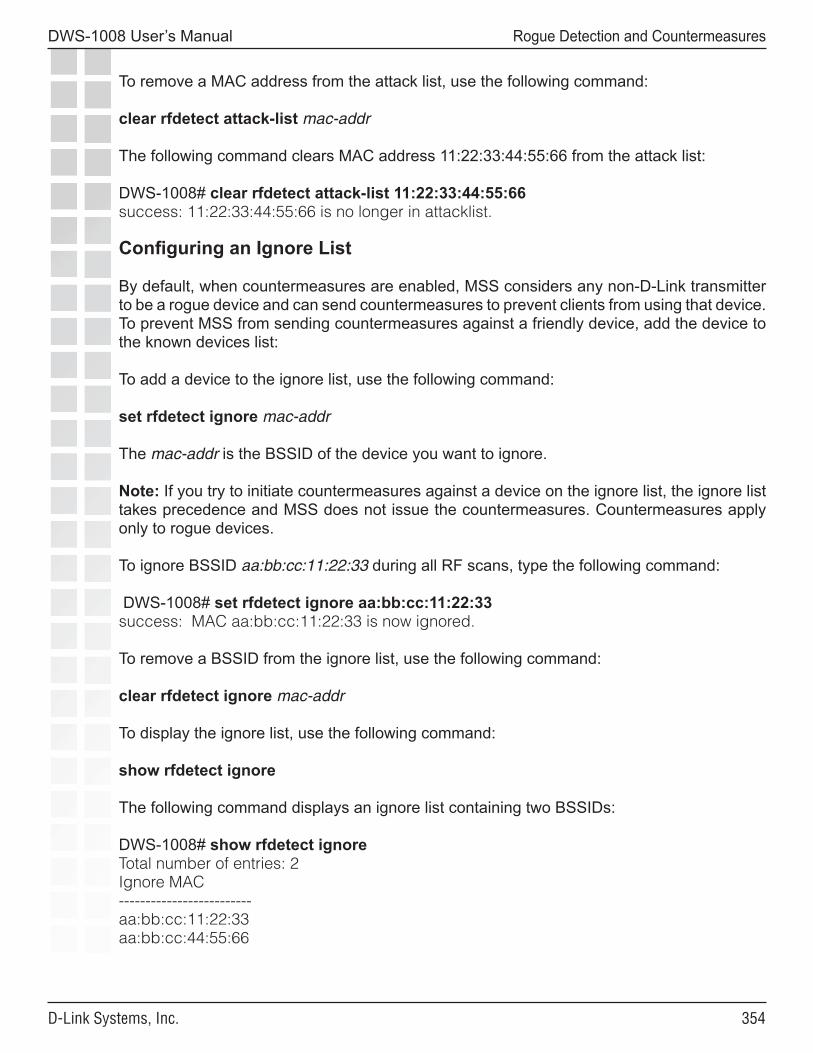
���
DWS-1008 User’s Manual
D-Link Systems, Inc.
Rogue Detection and Countermeasures
To remove a MAC address from the attack list, use the following command:
clear rfdetect attack-list mac-addr
The following command clears MAC address 11:22:33:44:55:66 from the attack list:
DWS-1008# clear rfdetect attack-list 11:22:33:44:55:66success: 11:22:33:44:55:66 is no longer in attacklist.
Configuring an Ignore List
By default, when countermeasures are enabled, MSS considers any non-D-Link transmitter to be a rogue device and can send countermeasures to prevent clients from using that device. To prevent MSS from sending countermeasures against a friendly device, add the device to the known devices list:
To add a device to the ignore list, use the following command:
set rfdetect ignore mac-addr
The mac-addr is the BSSID of the device you want to ignore.
Note: If you try to initiate countermeasures against a device on the ignore list, the ignore list takes precedence and MSS does not issue the countermeasures. Countermeasures apply only to rogue devices.
To ignore BSSID aa:bb:cc:11:22:33 during all RF scans, type the following command:
DWS-1008# set rfdetect ignore aa:bb:cc:11:22:33success: MAC aa:bb:cc:11:22:33 is now ignored.
To remove a BSSID from the ignore list, use the following command:
clear rfdetect ignore mac-addr
To display the ignore list, use the following command:
show rfdetect ignore
The following command displays an ignore list containing two BSSIDs:
DWS-1008# show rfdetect ignoreTotal number of entries: 2Ignore MAC-------------------------aa:bb:cc:11:22:33aa:bb:cc:44:55:66
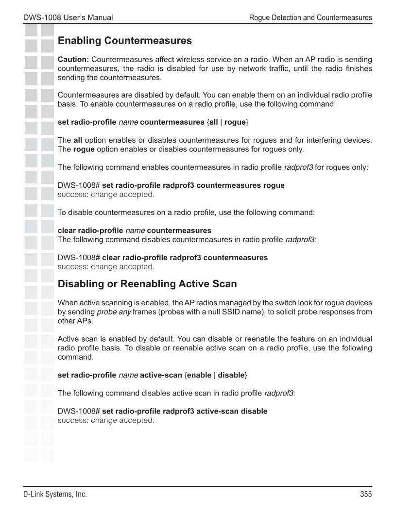
���
DWS-1008 User’s Manual
D-Link Systems, Inc.
Rogue Detection and Countermeasures
Enabling Countermeasures
Caution: Countermeasures affect wireless service on a radio. When an AP radio is sending countermeasures, the radio is disabled for use by network traffic, until the radio finishes sending the countermeasures.
Countermeasures are disabled by default. You can enable them on an individual radio profile basis. To enable countermeasures on a radio profile, use the following command:
set radio-profile name countermeasures {all | rogue}
The all option enables or disables countermeasures for rogues and for interfering devices. The rogue option enables or disables countermeasures for rogues only.
The following command enables countermeasures in radio profile radprof3 for rogues only:
DWS-1008# set radio-profile radprof3 countermeasures roguesuccess: change accepted.
To disable countermeasures on a radio profile, use the following command:
clear radio-profile name countermeasuresThe following command disables countermeasures in radio profile radprof3:
DWS-1008# clear radio-profile radprof3 countermeasuressuccess: change accepted.
Disabling or Reenabling Active Scan
When active scanning is enabled, the AP radios managed by the switch look for rogue devices by sending probe any frames (probes with a null SSID name), to solicit probe responses from other APs.
Active scan is enabled by default. You can disable or reenable the feature on an individual radio profile basis. To disable or reenable active scan on a radio profile, use the following command:
set radio-profile name active-scan {enable | disable}
The following command disables active scan in radio profile radprof3:
DWS-1008# set radio-profile radprof3 active-scan disablesuccess: change accepted.
���
DWS-1008 User’s Manual
D-Link Systems, Inc.
Rogue Detection and Countermeasures
Enabling AP Signatures
An AP signature is a set of bits in a management frame sent by an AP that identifies that AP to MSS. If someone attempts to spoof management packets from a D-Link AP, MSS can detect the spoof attempt.
AP signatures are disabled by default. To enable or disable them, use the following command:
set rfdetect signature {enable | disable}
The command applies only to APs managed by the switch on which you enter the command.
Disabling or Reenabling Logging of Rogues
By default, a DWS-1008 switch generates a log message when a rogue is detected or disappears. To disable or reenable the log messages, use the following command:
set rfdetect log {enable | disable}
To display log messages on a switch, use the following command:
show log buffer
Enabling Rogue and Countermeasures Notifications
By default, all SNMP notifications (informs or traps) are disabled. To enable or disable notifications for rogue detection, Intrusion Detection System (IDS), and Denial of Service (DoS) protection, configure a notification profile that sends all the notification types for these features.
IDS and DoS Alerts
MSS can detect illegitimate network access attempts and attempts to disrupt network service. In response, MSS generates messages and SNMP notifications. The following sections describe the types of attacks and security risks that MSS can detect.
Note: To detect DoS attacks, active scan must be enabled.
���
DWS-1008 User’s Manual
D-Link Systems, Inc.
Rogue Detection and Countermeasures
Flood Attacks
A flood attack is a type of Denial of Service attack. During a flood attack, a rogue wireless device attempts to overwhelm the resources of other wireless devices by continuously injecting management frames into the air. For example, a rogue client can repeatedly send association requests to try to overwhelm APs that receive the requests.
The threshold for triggering a flood message is 100 frames of the same type from the same MAC address, within a one-second period. If MSS detects more than 100 of the same type of wireless frame within one second, MSS generates a log message. The message indicates the frame type, the MAC address of the sender, the listener (AP and radio), channel number, and RSSI.
DoS Attacks
When active scan is enabled on APs, MSS can detect the following types of DoS attacks:
• RF Jamming - The goal of an RF jamming attack is to take down an entire WLAN by overwhelming the radio environment with high-power noise. A symptom of an RF jamming attack is excessive interference. If an AP radio detects excessive interference on a channel, and RF Auto-Tuning is enabled, MSS changes the radio to a different channel.
• Deauthenticate frames - Spoofed deauthenticate frames form the basis for most DoS attacks, and are the basis for other types of attacks including man-in-the-middle attacks. The source MAC address is spoofed so that clients think the packet is coming from a legitimate AP. If an AP detects a packet with its own source MAC address, the AP knows that the packet was spoofed.
• Broadcast deauthenticate frames - Similar to the spoofed deauthenticate frame attack above, a broadcast deauthenticate frame attack generates spoofed deauthenticate frames, with a broadcast destination address instead of the address of a specific client. The intent of the attack is to disconnect all stations attached to an AP.
• Disassociation frames - A disassociation frame from an AP instructs the client to end its association with the AP. The intent of this attack it to disconnect clients from the AP.
• Null probe responses - A client’s probe request frame is answered by a probe response containing a null SSID. Some NIC cards lock up upon receiving such a probe response.
• Decrypt errors - An excessive number of decrypt errors can indicate that multiple clients are using the same MAC address. A device’s MAC address is supposed to be unique. Multiple instances of the same address can indicate that a rogue device is pretending to be a legitimate device by spoofing its MAC address.
���
DWS-1008 User’s Manual
D-Link Systems, Inc.
Rogue Detection and Countermeasures
• Fake AP - A rogue device sends beacon frames for randomly generated SSIDs or BSSIDs. This type of attack can cause clients to become confused by the presence of so many SSIDs and BSSIDs, and thus interferes with the clients’ ability to connect to valid APs. This type of attack can also interfere with RF Auto-Tuning when an AP is trying to adjust to its RF neighborhood.
• SSID masquerade - A rogue device pretends to be a legitimate AP by sending beacon frames for a valid SSID serviced by APs in your network. Data from clients that associate with the rogue device can be accessed by the hacker controlling the rogue device.
• Spoofed AP - A rogue device pretends to be a D-Link AP by sending packets with the source MAC address of the D-Link AP. Data from clients that associate with the rogue device can be accessed by the hacker controlling the rogue device.
Note: MSS detects a spoofed AP attack based on the fingerprint of the spoofed AP. Packets from the real AP have the correct signature, while spoofed packets lack the signature.
Netstumbler and Wellenreiter Applications
Netstumbler and Wellenreiter are widely available applications that hackers can use to gather information about the APs in your network, including location, manufacturer, and encryption settings.
Wireless Bridge
A wireless bridge can extend a wireless network outside the desired area. For example, someone can place a wireless bridge near an exterior wall to extend wireless coverage out into the parking lot, where a hacker could then gain access to the network.
Ad-Hoc Network
An ad-hoc network is established directly among wireless clients and does not use the infrastructure network (a network using an AP). An Ad-hoc network might not be an intentionally malicious attack on the network, but it does steal bandwidth from your infrastructure users.
Weak WEP Key Used by Client
A weak initialization vector (IV) makes a WEP key easier to hack. MSS alerts you regarding clients who are using weak WEP IVs so that you can strengthen the encryption on these clients or replace the clients.
���
DWS-1008 User’s Manual
D-Link Systems, Inc.
Rogue Detection and Countermeasures
Disallowed Devices or SSIDs
You can configure the following types of lists to explicitly allow specific devices or SSIDs:
• Permitted SSID list - MSS generates a message if an SSID that is not on the list is detected.
• Permitted vendor list - MSS generates a message if an AP or wireless client with an OUI that is not on the list is detected.
• Client black list - MSS prevents clients on the list from accessing the network through a switch. If the client is placed on the black list dynamically by MSS due to an association, reassociation or disassociation flood, MSS generates a log message.
By default, these lists are empty and all SSIDs, vendors, and clients are allowed.
Displaying Statistics Counters
To display IDS and DoS statistics counters, use the show rfdetect counters commands.
IDS Log Message Examples
The table below shows examples of the log messages generated by IDS.
Message Type Example Log MessageProbe message flood
Client aa:bb:cc:dd:ee:ff is sending probe message flood. Seen by AP on port 2, radio 1 on channel 11 with RSSI -53.
Authentication message flood
Client aa:bb:cc:dd:ee:ff is sending authentication message flood. Seen by AP on port 2, radio 1 on channel 11 with RSSI -53.
Null data message flood
Client aa:bb:cc:dd:ee:ff is sending null data message flood. Seen by AP on port 2, radio 1 on channel 11 with RSSI -53.
Management frame 6 flood
Client aa:bb:cc:dd:ee:ff is sending rsvd mgmt frame 6 message flood. Seen by AP on port 2, radio 1 on channel 11 with RSSI -53.
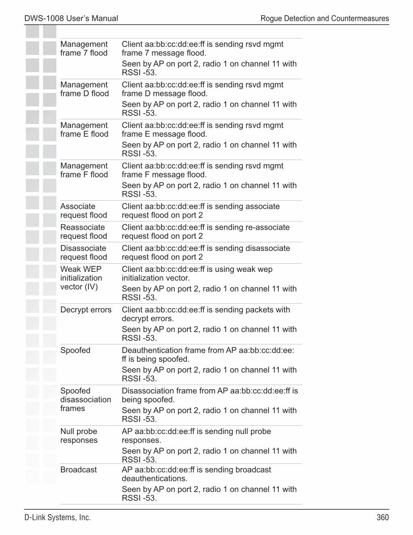
��0
DWS-1008 User’s Manual
D-Link Systems, Inc.
Rogue Detection and Countermeasures
Management frame 7 flood
Client aa:bb:cc:dd:ee:ff is sending rsvd mgmt frame 7 message flood. Seen by AP on port 2, radio 1 on channel 11 with RSSI -53.
Management frame D flood
Client aa:bb:cc:dd:ee:ff is sending rsvd mgmt frame D message flood. Seen by AP on port 2, radio 1 on channel 11 with RSSI -53.
Management frame E flood
Client aa:bb:cc:dd:ee:ff is sending rsvd mgmt frame E message flood. Seen by AP on port 2, radio 1 on channel 11 with RSSI -53.
Management frame F flood
Client aa:bb:cc:dd:ee:ff is sending rsvd mgmt frame F message flood. Seen by AP on port 2, radio 1 on channel 11 with RSSI -53.
Associate request flood
Client aa:bb:cc:dd:ee:ff is sending associate request flood on port 2
Reassociate request flood
Client aa:bb:cc:dd:ee:ff is sending re-associate request flood on port 2
Disassociate request flood
Client aa:bb:cc:dd:ee:ff is sending disassociate request flood on port 2
Weak WEP initialization vector (IV)
Client aa:bb:cc:dd:ee:ff is using weak wep initialization vector. Seen by AP on port 2, radio 1 on channel 11 with RSSI -53.
Decrypt errors Client aa:bb:cc:dd:ee:ff is sending packets with decrypt errors. Seen by AP on port 2, radio 1 on channel 11 with RSSI -53.
Spoofed Deauthentication frame from AP aa:bb:cc:dd:ee:ff is being spoofed. Seen by AP on port 2, radio 1 on channel 11 with RSSI -53.
Spoofed disassociation frames
Disassociation frame from AP aa:bb:cc:dd:ee:ff is being spoofed. Seen by AP on port 2, radio 1 on channel 11 with RSSI -53.
Null probe responses
AP aa:bb:cc:dd:ee:ff is sending null probe responses. Seen by AP on port 2, radio 1 on channel 11 with RSSI -53.
Broadcast AP aa:bb:cc:dd:ee:ff is sending broadcast deauthentications. Seen by AP on port 2, radio 1 on channel 11 with RSSI -53.
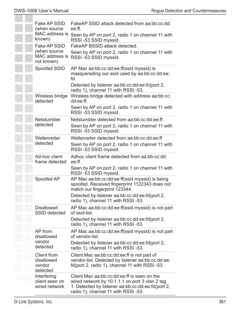
���
DWS-1008 User’s Manual
D-Link Systems, Inc.
Rogue Detection and Countermeasures
Fake AP SSID (when source MAC address is known)
FakeAP SSID attack detected from aa:bb:cc:dd:ee:ff. Seen by AP on port 2, radio 1 on channel 11 with RSSI -53 SSID myssid.
Fake AP SSID (when source MAC address is not known)
FakeAP BSSID attack detected. Seen by AP on port 2, radio 1 on channel 11 with RSSI -53 SSID myssid.
Spoofed SSID AP Mac aa:bb:cc:dd:ee:ff(ssid myssid) is masquerading our ssid used by aa:bb:cc:dd:ee:fd. Detected by listener aa:bb:cc:dd:ee:fc(port 2, radio 1), channel 11 with RSSI -53.
Wireless bridge detected
Wireless bridge detected with address aa:bb:cc:dd:ee:ff. Seen by AP on port 2, radio 1 on channel 11 with RSSI -53 SSID myssid.
Netstumbler detected
Netstumbler detected from aa:bb:cc:dd:ee:ff. Seen by AP on port 2, radio 1 on channel 11 with RSSI -53 SSID myssid.
Wellenreiter detected
Wellenreiter detected from aa:bb:cc:dd:ee:ff. Seen by AP on port 2, radio 1 on channel 11 with RSSI -53 SSID myssid.
Ad-hoc client frame detected
Adhoc client frame detected from aa:bb:cc:dd:ee:ff. Seen by AP on port 2, radio 1 on channel 11 with RSSI -53 SSID myssid.
Spoofed AP AP Mac aa:bb:cc:dd:ee:ff(ssid myssid) is being spoofed. Received fingerprint 1122343 does not match our fingerprint 123344. Detected by listener aa:bb:cc:dd:ee:fd(port 2, radio 1), channel 11 with RSSI -53.
Disallowed SSID detected
AP Mac aa:bb:cc:dd:ee:ff(ssid myssid) is not part of ssid-list. Detected by listener aa:bb:cc:dd:ee:fd(port 2, radio 1), channel 11 with RSSI -53.
AP from disallowed vendor detected
AP Mac aa:bb:cc:dd:ee:ff(ssid myssid) is not part of vendor-list. Detected by listener aa:bb:cc:dd:ee:fd(port 2, radio 1), channel 11 with RSSI -53.
Client from disallowed vendor detected
Client Mac aa:bb:cc:dd:ee:ff is not part of vendor-list. Detected by listener aa:bb:cc:dd:ee:fd(port 2, radio 1), channel 11 with RSSI -53.
Interfering client seen on wired network
Client Mac aa:bb:cc:dd:ee:ff is seen on the wired network by 10.1.1.1 on port 3 vlan 2 tag 1. Detected by listener aa:bb:cc:dd:ee:fd(port 2, radio 1), channel 11 with RSSI -53.
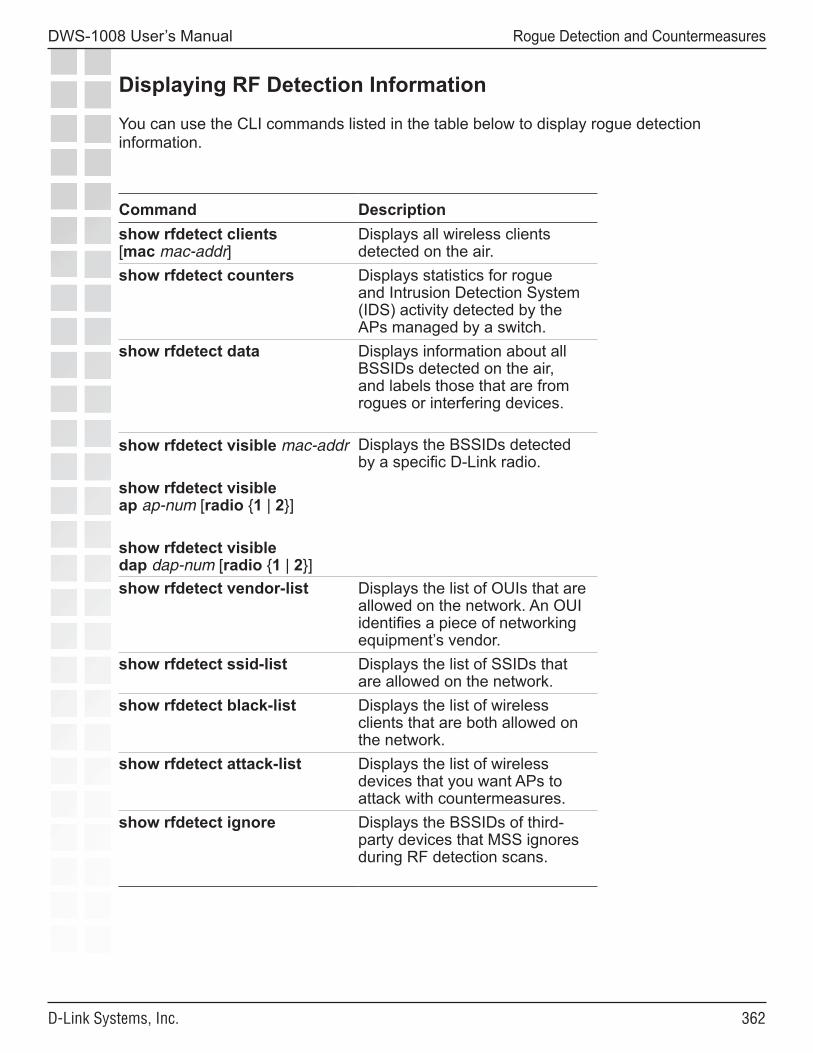
���
DWS-1008 User’s Manual
D-Link Systems, Inc.
Rogue Detection and Countermeasures
Displaying RF Detection Information
You can use the CLI commands listed in the table below to display rogue detection information.
Command Descriptionshow rfdetect clients [mac mac-addr]
Displays all wireless clients detected on the air.
show rfdetect counters Displays statistics for rogue and Intrusion Detection System (IDS) activity detected by the APs managed by a switch.
show rfdetect data Displays information about all BSSIDs detected on the air, and labels those that are from rogues or interfering devices.
show rfdetect visible mac-addr
show rfdetect visible ap ap-num [radio {1 | 2}]
show rfdetect visible dap dap-num [radio {1 | 2}]
Displays the BSSIDs detected by a specific D-Link radio.
show rfdetect vendor-list Displays the list of OUIs that are allowed on the network. An OUI identifies a piece of networking equipment’s vendor.
show rfdetect ssid-list Displays the list of SSIDs that are allowed on the network.
show rfdetect black-list Displays the list of wireless clients that are both allowed on the network.
show rfdetect attack-list Displays the list of wireless devices that you want APs to attack with countermeasures.
show rfdetect ignore Displays the BSSIDs of third-party devices that MSS ignores during RF detection scans.
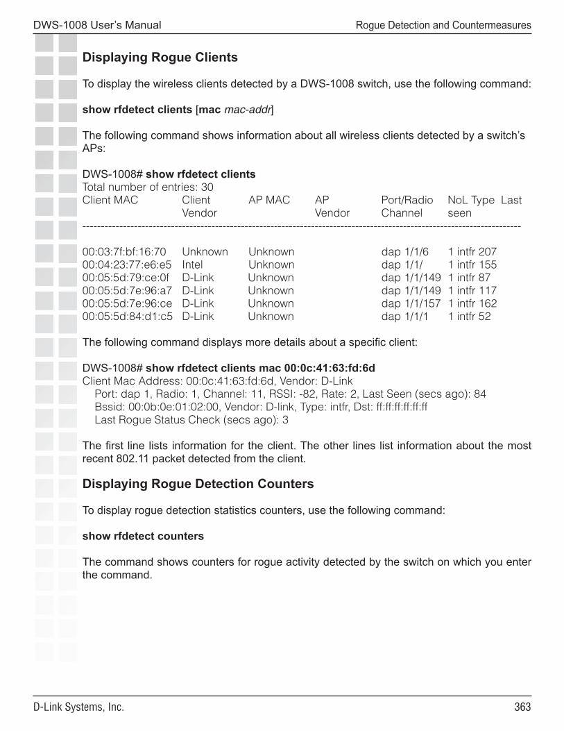
���
DWS-1008 User’s Manual
D-Link Systems, Inc.
Rogue Detection and Countermeasures
Displaying Rogue Clients
To display the wireless clients detected by a DWS-1008 switch, use the following command:
show rfdetect clients [mac mac-addr]
The following command shows information about all wireless clients detected by a switch’s APs:
DWS-1008# show rfdetect clientsTotal number of entries: 30Client MAC Client AP MAC AP Port/Radio NoL Type Last Vendor Vendor Channel seen-----------------------------------------------------------------------------------------------------------------------
00:03:7f:bf:16:70 Unknown Unknown dap 1/1/6 1 intfr 20700:04:23:77:e6:e5 Intel Unknown dap 1/1/ 1 intfr 15500:05:5d:79:ce:0f D-Link Unknown dap 1/1/149 1 intfr 8700:05:5d:7e:96:a7 D-Link Unknown dap 1/1/149 1 intfr 11700:05:5d:7e:96:ce D-Link Unknown dap 1/1/157 1 intfr 16200:05:5d:84:d1:c5 D-Link Unknown dap 1/1/1 1 intfr 52
The following command displays more details about a specific client:
DWS-1008# show rfdetect clients mac 00:0c:41:63:fd:6dClient Mac Address: 00:0c:41:63:fd:6d, Vendor: D-Link Port: dap 1, Radio: 1, Channel: 11, RSSI: -82, Rate: 2, Last Seen (secs ago): 84 Bssid: 00:0b:0e:01:02:00, Vendor: D-link, Type: intfr, Dst: ff:ff:ff:ff:ff:ff Last Rogue Status Check (secs ago): 3
The first line lists information for the client. The other lines list information about the most recent 802.11 packet detected from the client.
Displaying Rogue Detection Counters
To display rogue detection statistics counters, use the following command:
show rfdetect counters
The command shows counters for rogue activity detected by the switch on which you enter the command.
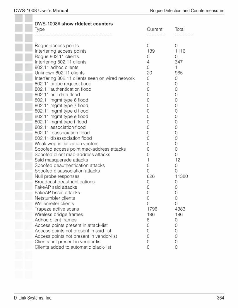
���
DWS-1008 User’s Manual
D-Link Systems, Inc.
Rogue Detection and Countermeasures
DWS-1008# show rfdetect countersType Current Total-------------------------------------------------- ------------ ------------
Rogue access points 0 0Interfering access points 139 1116Rogue 802.11 clients 0 0Interfering 802.11 clients 4 347802.11 adhoc clients 0 1Unknown 802.11 clients 20 965Interfering 802.11 clients seen on wired network 0 0802.11 probe request flood 0 0802.11 authentication flood 0 0802.11 null data flood 0 0802.11 mgmt type 6 flood 0 0802.11 mgmt type 7 flood 0 0802.11 mgmt type d flood 0 0802.11 mgmt type e flood 0 0802.11 mgmt type f flood 0 0802.11 association flood 0 0802.11 reassociation flood 0 0802.11 disassociation flood 0 0Weak wep initialization vectors 0 0Spoofed access point mac-address attacks 0 0Spoofed client mac-address attacks 0 0Ssid masquerade attacks 1 12Spoofed deauthentication attacks 0 0Spoofed disassociation attacks 0 0Null probe responses 626 11380Broadcast deauthentications 0 0FakeAP ssid attacks 0 0FakeAP bssid attacks 0 0Netstumbler clients 0 0Wellenreiter clients 0 0Trapeze active scans 1796 4383Wireless bridge frames 196 196Adhoc client frames 8 0Access points present in attack-list 0 0Access points not present in ssid-list 0 0Access points not present in vendor-list 0 0Clients not present in vendor-list 0 0Clients added to automatic black-list 0 0
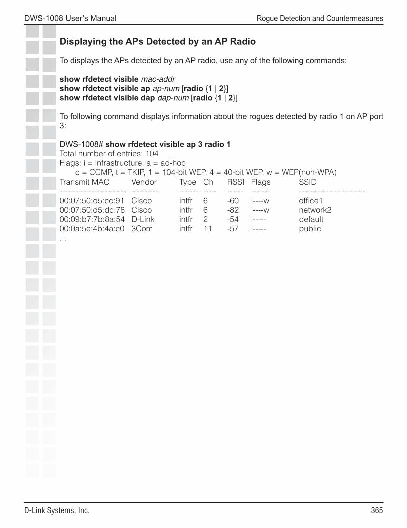
���
DWS-1008 User’s Manual
D-Link Systems, Inc.
Rogue Detection and Countermeasures
Displaying the APs Detected by an AP Radio
To displays the APs detected by an AP radio, use any of the following commands:
show rfdetect visible mac-addrshow rfdetect visible ap ap-num [radio {1 | 2}]show rfdetect visible dap dap-num [radio {1 | 2}]
To following command displays information about the rogues detected by radio 1 on AP port 3:
DWS-1008# show rfdetect visible ap 3 radio 1Total number of entries: 104Flags: i = infrastructure, a = ad-hoc c = CCMP, t = TKIP, 1 = 104-bit WEP, 4 = 40-bit WEP, w = WEP(non-WPA)Transmit MAC Vendor Type Ch RSSI Flags SSID------------------------- ---------- ------- ----- ------ ------- -------------------------00:07:50:d5:cc:91 Cisco intfr 6 -60 i----w office100:07:50:d5:dc:78 Cisco intfr 6 -82 i----w network200:09:b7:7b:8a:54 D-Link intfr 2 -54 i----- default00:0a:5e:4b:4a:c0 3Com intfr 11 -57 i----- public...
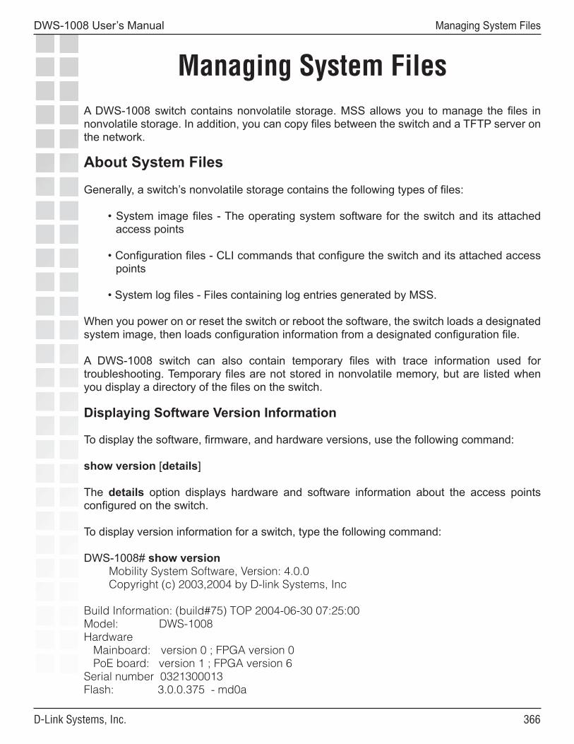
���
DWS-1008 User’s Manual
D-Link Systems, Inc.
Managing System Files
Managing System FilesA DWS-1008 switch contains nonvolatile storage. MSS allows you to manage the files in nonvolatile storage. In addition, you can copy files between the switch and a TFTP server on the network.
About System Files
Generally, a switch’s nonvolatile storage contains the following types of files:
• System image files - The operating system software for the switch and its attached access points
• Configuration files - CLI commands that configure the switch and its attached access points
• System log files - Files containing log entries generated by MSS.
When you power on or reset the switch or reboot the software, the switch loads a designated system image, then loads configuration information from a designated configuration file. A DWS-1008 switch can also contain temporary files with trace information used for troubleshooting. Temporary files are not stored in nonvolatile memory, but are listed when you display a directory of the files on the switch.
Displaying Software Version Information
To display the software, firmware, and hardware versions, use the following command:
show version [details]
The details option displays hardware and software information about the access points configured on the switch.
To display version information for a switch, type the following command:
DWS-1008# show version Mobility System Software, Version: 4.0.0 Copyright (c) 2003,2004 by D-link Systems, Inc
Build Information: (build#75) TOP 2004-06-30 07:25:00Model: DWS-1008Hardware Mainboard: version 0 ; FPGA version 0 PoE board: version 1 ; FPGA version 6Serial number 0321300013Flash: 3.0.0.375 - md0a
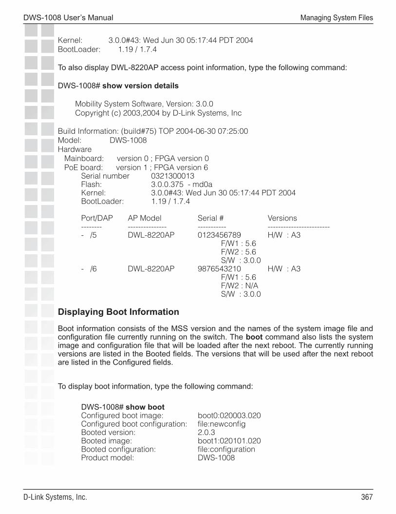
���
DWS-1008 User’s Manual
D-Link Systems, Inc.
Managing System Files
Kernel: 3.0.0#43: Wed Jun 30 05:17:44 PDT 2004BootLoader: 1.19 / 1.7.4
To also display DWL-8220AP access point information, type the following command:
DWS-1008# show version details
Mobility System Software, Version: 3.0.0 Copyright (c) 2003,2004 by D-Link Systems, Inc
Build Information: (build#75) TOP 2004-06-30 07:25:00Model: DWS-1008Hardware Mainboard: version 0 ; FPGA version 0 PoE board: version 1 ; FPGA version 6
Serial number 0321300013Flash: 3.0.0.375 - md0aKernel: 3.0.0#43: Wed Jun 30 05:17:44 PDT 2004BootLoader: 1.19 / 1.7.4
Port/DAP AP Model Serial # Versions-------- --------------- ----------- ------------------------- /5 DWL-8220AP 0123456789 H/W : A3 F/W1 : 5.6 F/W2 : 5.6 S/W : 3.0.0- /6 DWL-8220AP 9876543210 H/W : A3 F/W1 : 5.6 F/W2 : N/A S/W : 3.0.0
Displaying Boot Information
Boot information consists of the MSS version and the names of the system image file and configuration file currently running on the switch. The boot command also lists the system image and configuration file that will be loaded after the next reboot. The currently running versions are listed in the Booted fields. The versions that will be used after the next reboot are listed in the Configured fields.
To display boot information, type the following command:
DWS-1008# show bootConfigured boot image: boot0:020003.020Configured boot configuration: file:newconfigBooted version: 2.0.3Booted image: boot1:020101.020Booted configuration: file:configurationProduct model: DWS-1008
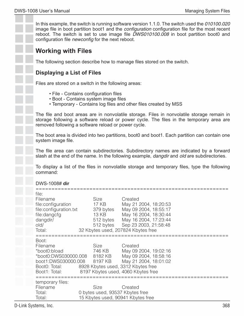
���
DWS-1008 User’s Manual
D-Link Systems, Inc.
Managing System Files
In this example, the switch is running software version 1.1.0. The switch used the 010100.020 image file in boot partition boot1 and the configuration configuration file for the most recent reboot. The switch is set to use image file DWS010100.008 in boot partition boot0 and configuration file newconfig for the next reboot.
Working with FilesThe following section describe how to manage files stored on the switch.
Displaying a List of Files
Files are stored on a switch in the following areas:
• File - Contains configuration files• Boot - Contains system image files• Temporary - Contains log files and other files created by MSS
The file and boot areas are in nonvolatile storage. Files in nonvolatile storage remain in storage following a software reload or power cycle. The files in the temporary area are removed following a software reload or power cycle.
The boot area is divided into two partitions, boot0 and boot1. Each partition can contain one system image file.
The file area can contain subdirectories. Subdirectory names are indicated by a forward slash at the end of the name. In the following example, dangdir and old are subdirectories.
To display a list of the files in nonvolatile storage and temporary files, type the following command:
DWS-1008# dir=============================================================file:Filename Size Createdfile:configuration 17 KB May 21 2004, 18:20:53file:configuration.txt 379 bytes May 09 2004, 18:55:17file:dangcfg 13 KB May 16 2004, 18:30:44dangdir/ 512 bytes May 16 2004, 17:23:44old/ 512 bytes Sep 23 2003, 21:58:48Total: 32 Kbytes used, 207824 Kbytes free=============================================================Boot:Filename Size Created*boot0:bload 746 KB May 09 2004, 19:02:16*boot0:DWS030000.008 8182 KB May 09 2004, 18:58:16boot1:DWS030000.008 8197 KB May 21 2004, 18:01:02Boot0: Total: 8928 Kbytes used, 3312 Kbytes freeBoot1: Total: 8197 Kbytes used, 4060 Kbytes free=============================================================temporary files:Filename Size CreatedTotal: 0 bytes used, 93537 Kbytes freeTotal: 15 Kbytes used, 90941 Kbytes free
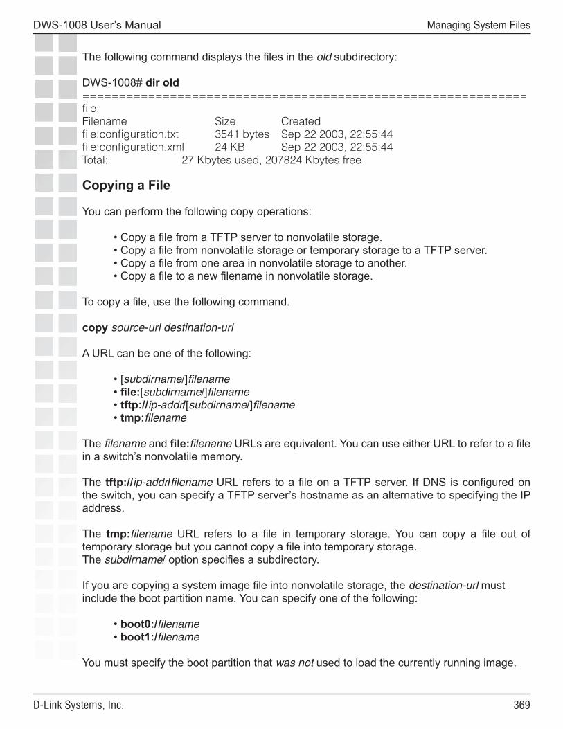
���
DWS-1008 User’s Manual
D-Link Systems, Inc.
Managing System Files
The following command displays the files in the old subdirectory:
DWS-1008# dir old=============================================================file:Filename Size Createdfile:configuration.txt 3541 bytes Sep 22 2003, 22:55:44file:configuration.xml 24 KB Sep 22 2003, 22:55:44Total: 27 Kbytes used, 207824 Kbytes free
Copying a File
You can perform the following copy operations:
• Copy a file from a TFTP server to nonvolatile storage.• Copy a file from nonvolatile storage or temporary storage to a TFTP server.• Copy a file from one area in nonvolatile storage to another. • Copy a file to a new filename in nonvolatile storage.
To copy a file, use the following command.
copy source-url destination-url
A URL can be one of the following:
• [subdirname/]filename• file:[subdirname/]filename• tftp://ip-addr/[subdirname/]filename• tmp:filename
The filename and file:filename URLs are equivalent. You can use either URL to refer to a file in a switch’s nonvolatile memory.
The tftp://ip-addr/filename URL refers to a file on a TFTP server. If DNS is configured on the switch, you can specify a TFTP server’s hostname as an alternative to specifying the IP address.
The tmp:filename URL refers to a file in temporary storage. You can copy a file out of temporary storage but you cannot copy a file into temporary storage.The subdirname/ option specifies a subdirectory.
If you are copying a system image file into nonvolatile storage, the destination-url must include the boot partition name. You can specify one of the following:
• boot0:/filename• boot1:/filename
You must specify the boot partition that was not used to load the currently running image.
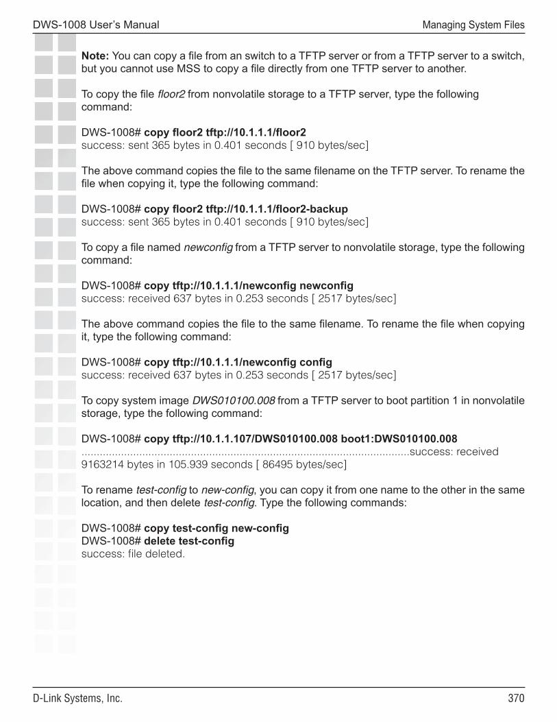
��0
DWS-1008 User’s Manual
D-Link Systems, Inc.
Managing System Files
Note: You can copy a file from an switch to a TFTP server or from a TFTP server to a switch, but you cannot use MSS to copy a file directly from one TFTP server to another.
To copy the file floor2 from nonvolatile storage to a TFTP server, type the following command:
DWS-1008# copy floor2 tftp://10.1.1.1/floor2success: sent 365 bytes in 0.401 seconds [ 910 bytes/sec]
The above command copies the file to the same filename on the TFTP server. To rename the file when copying it, type the following command:
DWS-1008# copy floor2 tftp://10.1.1.1/floor2-backupsuccess: sent 365 bytes in 0.401 seconds [ 910 bytes/sec]
To copy a file named newconfig from a TFTP server to nonvolatile storage, type the following command:
DWS-1008# copy tftp://10.1.1.1/newconfig newconfigsuccess: received 637 bytes in 0.253 seconds [ 2517 bytes/sec]
The above command copies the file to the same filename. To rename the file when copying it, type the following command:
DWS-1008# copy tftp://10.1.1.1/newconfig configsuccess: received 637 bytes in 0.253 seconds [ 2517 bytes/sec]
To copy system image DWS010100.008 from a TFTP server to boot partition 1 in nonvolatile storage, type the following command:
DWS-1008# copy tftp://10.1.1.107/DWS010100.008 boot1:DWS010100.008............................................................................................................success: received 9163214 bytes in 105.939 seconds [ 86495 bytes/sec]
To rename test-config to new-config, you can copy it from one name to the other in the same location, and then delete test-config. Type the following commands:
DWS-1008# copy test-config new-configDWS-1008# delete test-configsuccess: file deleted.
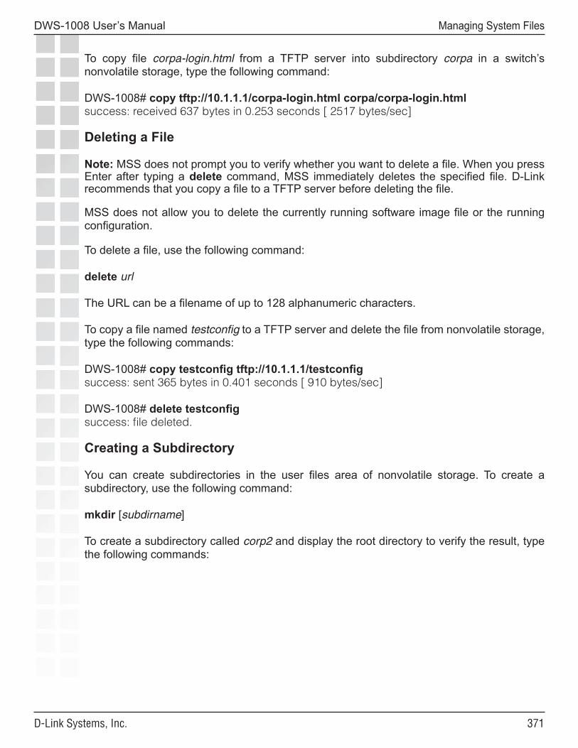
���
DWS-1008 User’s Manual
D-Link Systems, Inc.
Managing System Files
To copy file corpa-login.html from a TFTP server into subdirectory corpa in a switch’s nonvolatile storage, type the following command:
DWS-1008# copy tftp://10.1.1.1/corpa-login.html corpa/corpa-login.htmlsuccess: received 637 bytes in 0.253 seconds [ 2517 bytes/sec]
Deleting a File
Note: MSS does not prompt you to verify whether you want to delete a file. When you press Enter after typing a delete command, MSS immediately deletes the specified file. D-Link recommends that you copy a file to a TFTP server before deleting the file.
MSS does not allow you to delete the currently running software image file or the running configuration.
To delete a file, use the following command:
delete url
The URL can be a filename of up to 128 alphanumeric characters.
To copy a file named testconfig to a TFTP server and delete the file from nonvolatile storage, type the following commands:
DWS-1008# copy testconfig tftp://10.1.1.1/testconfigsuccess: sent 365 bytes in 0.401 seconds [ 910 bytes/sec]
DWS-1008# delete testconfigsuccess: file deleted.
Creating a Subdirectory
You can create subdirectories in the user files area of nonvolatile storage. To create a subdirectory, use the following command:
mkdir [subdirname]
To create a subdirectory called corp2 and display the root directory to verify the result, type the following commands:
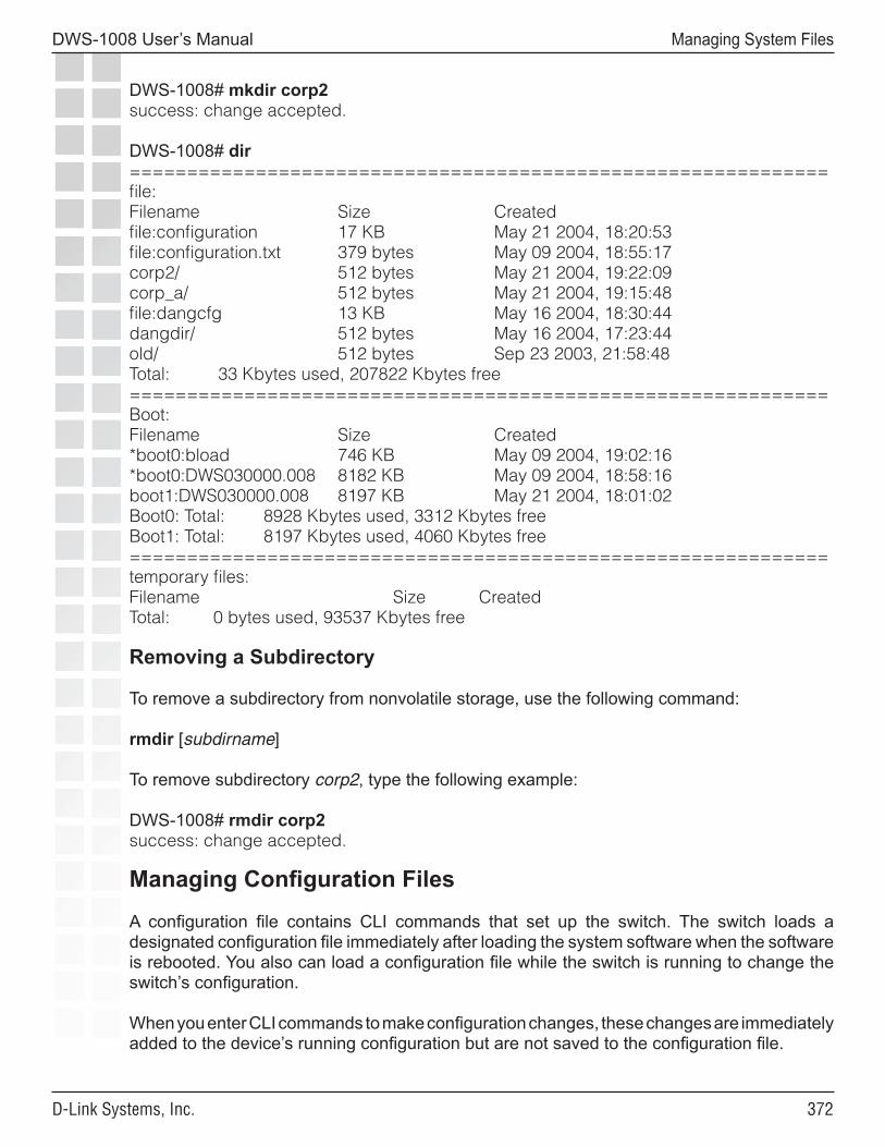
���
DWS-1008 User’s Manual
D-Link Systems, Inc.
Managing System Files
DWS-1008# mkdir corp2success: change accepted.
DWS-1008# dir=============================================================file:Filename Size Createdfile:configuration 17 KB May 21 2004, 18:20:53file:configuration.txt 379 bytes May 09 2004, 18:55:17corp2/ 512 bytes May 21 2004, 19:22:09corp_a/ 512 bytes May 21 2004, 19:15:48file:dangcfg 13 KB May 16 2004, 18:30:44dangdir/ 512 bytes May 16 2004, 17:23:44old/ 512 bytes Sep 23 2003, 21:58:48Total: 33 Kbytes used, 207822 Kbytes free=============================================================Boot:Filename Size Created*boot0:bload 746 KB May 09 2004, 19:02:16*boot0:DWS030000.008 8182 KB May 09 2004, 18:58:16boot1:DWS030000.008 8197 KB May 21 2004, 18:01:02Boot0: Total: 8928 Kbytes used, 3312 Kbytes freeBoot1: Total: 8197 Kbytes used, 4060 Kbytes free=============================================================temporary files:Filename Size CreatedTotal: 0 bytes used, 93537 Kbytes free
Removing a Subdirectory
To remove a subdirectory from nonvolatile storage, use the following command:
rmdir [subdirname]
To remove subdirectory corp2, type the following example:
DWS-1008# rmdir corp2success: change accepted.
Managing Configuration Files
A configuration file contains CLI commands that set up the switch. The switch loads a designated configuration file immediately after loading the system software when the software is rebooted. You also can load a configuration file while the switch is running to change the switch’s configuration.
When you enter CLI commands to make configuration changes, these changes are immediately added to the device’s running configuration but are not saved to the configuration file.
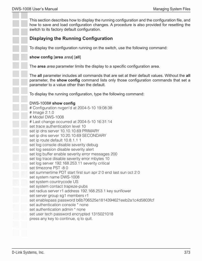
���
DWS-1008 User’s Manual
D-Link Systems, Inc.
Managing System Files
This section describes how to display the running configuration and the configuration file, and how to save and load configuration changes. A procedure is also provided for resetting the switch to its factory default configuration.
Displaying the Running Configuration
To display the configuration running on the switch, use the following command:
show config [area area] [all]
The area area parameter limits the display to a specific configuration area.
The all parameter includes all commands that are set at their default values. Without the all parameter, the show config command lists only those configuration commands that set a parameter to a value other than the default.
To display the running configuration, type the following command:
DWS-1008# show config# Configuration nvgen’d at 2004-5-10 19:08:38# Image 2.1.0# Model DWS-1008# Last change occurred at 2004-5-10 16:31:14set trace authentication level 10set ip dns server 10.10.10.69 PRIMARYset ip dns server 10.20.10.69 SECONDARYset ip route default 10.8.1.1 1set log console disable severity debugset log session disable severity alertset log buffer enable severity error messages 200set log trace disable severity error mbytes 10set log server 192.168.253.11 severity criticalset timezone PST -8 0set summertime PDT start first sun apr 2 0 end last sun oct 2 0set system name DWS-1008set system countrycode USset system contact trapeze-pubsset radius server r1 address 192.168.253.1 key sunflowerset server group sg1 members r1set enablepass password b6b706525e1814394621eeb2a1c4d5803fcfset authentication console * noneset authentication admin * noneset user tech password encrypted 1315021018press any key to continue, q to quit.
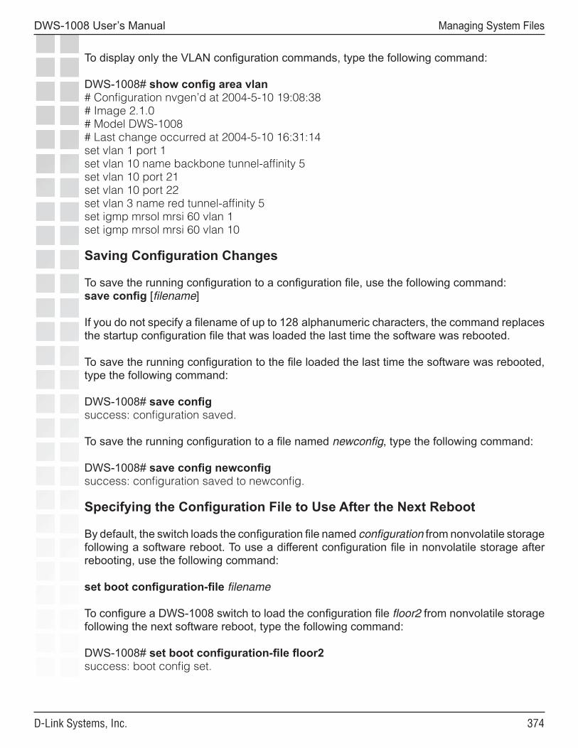
���
DWS-1008 User’s Manual
D-Link Systems, Inc.
Managing System Files
To display only the VLAN configuration commands, type the following command:
DWS-1008# show config area vlan# Configuration nvgen’d at 2004-5-10 19:08:38# Image 2.1.0# Model DWS-1008# Last change occurred at 2004-5-10 16:31:14set vlan 1 port 1set vlan 10 name backbone tunnel-affinity 5set vlan 10 port 21set vlan 10 port 22set vlan 3 name red tunnel-affinity 5set igmp mrsol mrsi 60 vlan 1set igmp mrsol mrsi 60 vlan 10
Saving Configuration Changes
To save the running configuration to a configuration file, use the following command:save config [filename]
If you do not specify a filename of up to 128 alphanumeric characters, the command replaces the startup configuration file that was loaded the last time the software was rebooted.
To save the running configuration to the file loaded the last time the software was rebooted, type the following command:
DWS-1008# save configsuccess: configuration saved.
To save the running configuration to a file named newconfig, type the following command:
DWS-1008# save config newconfigsuccess: configuration saved to newconfig.
Specifying the Configuration File to Use After the Next Reboot
By default, the switch loads the configuration file named configuration from nonvolatile storage following a software reboot. To use a different configuration file in nonvolatile storage after rebooting, use the following command:
set boot configuration-file filename
To configure a DWS-1008 switch to load the configuration file floor2 from nonvolatile storage following the next software reboot, type the following command:
DWS-1008# set boot configuration-file floor2success: boot config set.
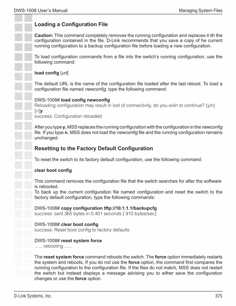
���
DWS-1008 User’s Manual
D-Link Systems, Inc.
Managing System Files
Loading a Configuration File
Caution: This command completely removes the running configuration and replaces it ith the configuration contained in the file. D-Link recommends that you save a copy of he current running configuration to a backup configuration file before loading a new configuration.
To load configuration commands from a file into the switch’s running configuration, use the following command:
load config [url]
The default URL is the name of the configuration file loaded after the last reboot. To load a configuration file named newconfig, type the following command:
DWS-1008# load config newconfigReloading configuration may result in lost of connectivity, do you wish to continue? (y/n) [n]ysuccess: Configuration reloaded
After you type y, MSS replaces the running configuration with the configuration in the newconfig file. If you type n, MSS does not load the newconfig file and the running configuration remains unchanged.
Resetting to the Factory Default Configuration
To reset the switch to its factory default configuration, use the following command:
clear boot config
This command removes the configuration file that the switch searches for after the software is rebooted. To back up the current configuration file named configuration and reset the switch to the factory default configuration, type the following commands:
DWS-1008# copy configuration tftp://10.1.1.1/backupcfgsuccess: sent 365 bytes in 0.401 seconds [ 910 bytes/sec]
DWS-1008# clear boot configsuccess: Reset boot config to factory defaults.
DWS-1008# reset system force...... rebooting ......
The reset system force command reboots the switch. The force option immediately restarts the system and reboots. If you do not use the force option, the command first compares the running configuration to the configuration file. If the files do not match, MSS does not restart the switch but instead displays a message advising you to either save the configuration changes or use the force option.
���
DWS-1008 User’s Manual
D-Link Systems, Inc.
Managing System Files
Backing Up and Restoring the System
MSS has commands that enable you to easily backup and restore system and user files:
backup system [tftp:/ip-addr/]filename [all | critical]restore system [tftp:/ip-addr/]filename [all | critical] [force]
The backup command creates an archive in Unix tape archive (tar) format.
The restore command unzips an archive created by the backup command and copies the files from the archive onto the switch. If a file in the archive has a counterpart on the switch, the archive version of the file replaces the file on the switch. The restore command does not delete files that do not have counterparts in the archive. For example, the command does not completely replace the user files area. Instead, files in the archive are added to the user files area. A file in the user area is replaced only if the archive contains a file with the same name.
You can create or unzip an archive located on a TFTP server or in the switch’s nonvolatile storage. If you specify a TFTP server as part of the filename with the backup command, the archive is copied directly to the TFTP server and not stored locally on the switch.
Both commands have options to specify the types of files you want to back up and restore:
• critical - Backs up or restores system files, including the configuration file used when booting, and certificate files. The size of an archive created by this option is generally 1MB or less. This is the default for the restore command.
• all - Backs up or restores the same files as the critical option, and all files in the user files area of nonvolatile storage. (The user files area contains the set of files listed in the file section of dir command output.) Archive files created by the all option are larger than files created by the critical option. The file size depends on the files in the user area, and the file can be quite large if the user area contains image files. This is the default for the backup command.
Note: If the archive’s files cannot fit on the switch, the restore operation fails. D-Link recommends deleting unneeded image files before creating or restoring an archive.
Use the critical option if you want to back up or restore only the system-critical files required to operate and communicate with the switch. Use the all option if you also want to backup configuration files, image files, and any other files stored in the user files area of nonvolatile storage.
Neither option archives image files or any other files listed in the Boot section of dir command output. The all option archives image files only if they are present in the user files area.
The backup command stores the MAC address of the switch in the archive. By default, the restore command works only if the MAC address in the archive matches the MAC address of the switch where the restore command is entered. The force option overrides this restriction and allows you to unpack one switch’s archive onto another switch.
���
DWS-1008 User’s Manual
D-Link Systems, Inc.
Managing System Files
Caution: Do not use the force option unless advised to do so by D-Link TAC. If you restore one switch’s system files onto another switch, you must generate new key pairs and certificates on the switch.
Managing Configuration Changes
The backup command places the boot configuration file into the archive. (The boot configuration file is the Configured boot configuration in the show boot command’s output.) If the running configuration contains changes that have not been saved, these changes are not in the boot configuration file and are not archived. To make sure the archive contains the configuration that is currently running on the switch, use the save config command to save the running configuration to the boot configuration file, before using the backup command.
The restore command replaces the boot configuration on the switch with the one in the archive. The boot configuration includes the configuration filename and the image filename to use after the next switch restart. (These are the Configured boot image and Configured boot configuration files listed in the show boot command’s output.) The restore command does not affect the running image or the running configuration.
If you want to use the configuration in the boot configuration file restored from an archive instead of the configuration currently running on the switch, use the load config command to load the boot configuration file, or restart the switch. If instead, you want to replace the configuration restored from the archive with the running configuration, use the save config command to save the running configuration to the boot configuration file.
Note: The next time the switch is restarted after the restore command is used, the switch uses the boot configuration filename that was in use when the archive was created. If you change the boot configuration filename after creating the archive, the new name is not used when the switch is restarted. To use the new configuration, use the save config filename command, where filename is the name of the boot configuration file restored from the archive, before you restart the switch. If you have already restarted the switch, use the load config filename command to load the new configuration, then use the save config filename command.
Backup and Restore Examples
The following command creates an archive of the system-critical files and copies the archive directly to a TFTP server. The filename in this example includes a TFTP server IP address, so the archive is not stored locally on the switch.
DWS-1008# backup system tftp:/10.10.20.9/sysa_bak criticalsuccess: sent 28263 bytes in 0.324 seconds [ 87231 bytes/sec]
The following command restores system-critical files on a switch, from archive sysa_bak:
DWS-1008# restore system tftp:/10.10.20.9/sysa_baksuccess: received 11908 bytes in 0.150 seconds [ 79386 bytes/sec]success: restore complete.
���
DWS-1008 User’s Manual
D-Link Systems, Inc.
Appendix A - Troubleshooting
TroubleshootingSome common problems that occur during installation and basic configuration are simple to solve. However, to “recover” the system password, you must delete the existing configuration.
System logs provide a history of MSS events. Traces display real-time messages from all MSS areas. Some show commands are particularly useful in troubleshooting. The show tech-support command combines a number of show commands into one, and provides an extensive snapshot of your switch configuration settings for the D-Link Technical Support.
Fixing Common Setup Problems
The table below contains remedies for some common problems that can occur during basic installation and setup of a DWS-1008 switch.
Setup Problems and Remedies Symptom Diagnosis RemedySwitch does not accept configuration information for an DWL-8220AP access point or a radio.
The country code might not be set or might be set for another country.
1. Type the show system command to display the country code configured on the switch.
2. If the value in the System Countrycode field is NONE or is for a country other than the one in which you are operating the switch, use the set system countrycode command to configure the correct country code. (See “Specifying the Country of Operation” on page 38.)
���
DWS-1008 User’s Manual
D-Link Systems, Inc.
Appendix A - Troubleshooting
Client cannot access the network.
This symptom has more than one possible cause: • The client
might be failing authentication or might not be authorized for a VLAN.
1. Type the show aaa command to ensure that the authentication rules on the switch allow the client to authenticate.
2. Check the authorization rules in the switch’s local database (show aaa) or on the RADIUS servers to ensure the client is authorized to join a VLAN that is configured on the switch.
• If the client and switch configurations are correct, a VLAN might be disconnected. A client connected to a disconnected VLAN is unable to access the network.
1. Type the show vlan config command to check the status of each VLAN.
2. If a VLAN is disconnected (VLAN state is Down), check the network cables for the VLAN’s ports. At least one of the ports in a VLAN must have a physical link to the network for the VLAN to be connected.
Configuration information disappears after a software reload.
The configuration changes were not saved.
1. Retype the commands for the missing configuration information.
2. Type the save config command to save the changes.
Mgmt LED is quickly blinking amber.CLI stops at boot prompt (boot>).
The switch was unable to load the system image file.
Type the boot command at the boot prompt.
��0
DWS-1008 User’s Manual
D-Link Systems, Inc.
Appendix A - Troubleshooting
Recovering the System PasswordYou can recover the system enable password if you have lost or forgotten it.
Caution: Recovering the system password will delete your configuration files.
You set the switch password using the set enablepass command. If you forget the password, use one of the following procedures.
1. Reboot the switch, and interrupt the switch boot process. Power the switch off and on again to cause the switch to reboot.
2. When you see descending numbers on the console, press q followed by Enter to abort booting.
3. Type the following command at the boot> prompt:
boot> boot OPT+=default
If you do not type the command before the reset cycle is complete, the switch returns to the state it was in before you restarted it.
Once you have entered the command, the switch returns to its initial unconfigured state.
Caution: Use an enable password that you will remember. If you lose the password, the only way to restore it causes the system to return to its default settings and wipes out the configuration.
Configuring and Managing the System Log
System logs provide information about system events that you can use to monitor and troubleshoot MSS. Event messages for the switch and its attached access points can be stored or sent to the following destinations:
• Stored in a local buffer on the switch• Displayed on the console port• Displayed in an active Telnet session• Sent to one or more syslog servers, as specified in RFC 3164
The system log is a file in which the newest record replaces the oldest. These entries are preserved in nonvolatile memory through system reboots.

���
DWS-1008 User’s Manual
D-Link Systems, Inc.
Appendix A - Troubleshooting
Log Message Components
Each log message contains the following components:
Field DescriptionFacility Portion of MSS that is affectedDate Time and date the message is generatedSeverity Severity level of the message.
Tag Identifier for the messageMessage Description of the error condition
Logging Destinations and Levels
A logging destination is the location to which logged event messages are sent for storage or display. By default, only session logging is disabled. You can enable or disable logging to each destination and filter the messages by the severity of the logged event or condition.
System events and conditions at different severity levels can be logged to multiple destinations. By default, events at the error level and higher are posted to the console and to the log buffer. Debug output is logged to the trace buffer by default. The table below summarizes the destinations and defaults for system log messages.
System Log Destinations and Defaults
Destination Definition Default Operation and Severity Level
buffer Sends log information to the nonvolatile system buffer.
Buffer is enabled and shows error-level events.
console Sends log information to the console.
Console is enabled and shows error-level events.
current Sends log information to the current Telnet or console session.
Settings for the type of session that the user is currently having with the switch
server ip-address Sends log information to the syslog server at the specified IP address.
Server is set during configuration and displays error-level events.
sessions Sets defaults for Telnet sessions.
Logging is disabled and shows information-level events when enabled.
trace Sends log information to the volatile trace buffer.
Trace is enabled and shows debug output.
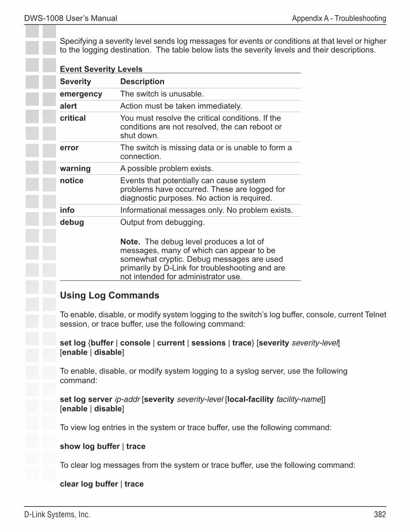
���
DWS-1008 User’s Manual
D-Link Systems, Inc.
Appendix A - Troubleshooting
Specifying a severity level sends log messages for events or conditions at that level or higher to the logging destination. The table below lists the severity levels and their descriptions.
Event Severity LevelsSeverity Descriptionemergency The switch is unusable.alert Action must be taken immediately.critical You must resolve the critical conditions. If the
conditions are not resolved, the can reboot or shut down.
error The switch is missing data or is unable to form a connection.
warning A possible problem exists.notice Events that potentially can cause system
problems have occurred. These are logged for diagnostic purposes. No action is required.
info Informational messages only. No problem exists.debug Output from debugging.
Note. The debug level produces a lot of messages, many of which can appear to be somewhat cryptic. Debug messages are used primarily by D-Link for troubleshooting and are not intended for administrator use.
Using Log Commands
To enable, disable, or modify system logging to the switch’s log buffer, console, current Telnet session, or trace buffer, use the following command:
set log {buffer | console | current | sessions | trace} [severity severity-level] [enable | disable]
To enable, disable, or modify system logging to a syslog server, use the following command:
set log server ip-addr [severity severity-level [local-facility facility-name]] [enable | disable]
To view log entries in the system or trace buffer, use the following command:
show log buffer | trace
To clear log messages from the system or trace buffer, use the following command:
clear log buffer | trace
���
DWS-1008 User’s Manual
D-Link Systems, Inc.
Appendix A - Troubleshooting
To stop sending messages to a syslog server, use the following command:
clear log server ip-addr
Logging to the Log Buffer
The system log consists of rolling entries stored as a last-in first-out queue maintained by the switch. Logging to the buffer is enabled by default for events at the error level and higher.
To modify settings to another severity level, use the following command:
set log buffer severity severity-level
For example, to set logging to the buffer for events at the warning level and higher, type the following command:
DWS-1008# set log buffer severity warningsuccess: change accepted.
To view log entries in the system log buffer, use the following command:
show log buffer [{+|-} number-of-messages] [facility facility-name] [matching string] [severity severity-level]
You can display the most recent messages or the oldest messages:
• Type a positive number (for example, +100) to display that number of log entries starting from the oldest in the log.
• Type a negative number (for example, -100) to display that number of log entries starting from the newest in the log.
You can search for strings by using the keyword matching and typing any string, such as a username or IP address.
You can display event information at a particular severity level.
For example, the following command displays all messages at the error severity level or higher:
DWS-1008# show log buffer severity errorSYS Jun 02 17:41:35. 176214 ERROR nos_vms_port?add: Failed to set default vlan v1 an:4096 for port 3 rc 1
���
DWS-1008 User’s Manual
D-Link Systems, Inc.
Appendix A - Troubleshooting
To filter the event log by MSS area, use the facility facility-name keyword. For a list of facilities for which you can view event messages, type the following command:
DWS-1008# show log buffer facility ?<facility name> Select one of: KERNEL, AAA, SYSLOGD, ACL, APM, ARP,ASO, BOOT, CLI, CLUSTER, COPP, CRYPTO, DOT1X, ENCAP, ETHERNET, GATEWAY, IGMP, IP, MISC, NOSE, NP, RAND, RESOLV, RIB, ROAM, ROGUE, SM, SNMPD, SPAN, STORE, SYS, TAGMGR, TBRIDGE, TCPSSL, TELNET, TFTP, TLS, TUNNEL, VLAN, X509, XML, AP, RAPDA, EAP, PORTCONFIG, FP.
To clear the buffer, type the following command:
DWS-1008# clear log buffer
To disable logging to the system buffer, type the following command:
DWS-1008# set log buffer disable
Logging to the Console
By default, console logging is enabled and messages at the error level and higher are sent to the console.
To modify console logging, use the following command:
set log console severity severity-level
For example, to set logging to the console for events at the critical severity level and higher, type the following command:
DWS-1008# set log console severity criticalsuccess: command accepted.
To disable console logging, type the following command:
DWS-1008# set log console disablesuccess: change accepted.
The console is always available, but it has the following limitations:
• Console logging is slow.• Messages logged to the console are dropped if the console output buffer overflows.
MSS displays a message indicating the number of messages dropped.• If you type anything to the console, the typing disables log output to the console until
you press the Enter key.
���
DWS-1008 User’s Manual
D-Link Systems, Inc.
Appendix A - Troubleshooting
Logging Messages to a Syslog Server
To send event messages to a syslog server, use the following command:
set log server ip-addr severity severity-level [local-facility facility-name] enable
Use the IP address of the syslog server to which you want messages sent.
Use the optional local-facility keyword to override the default MSS facility numbers and replace them with one local facility number. Use the numbers 0 through 7 to map MSS event messages to one of the standard local log facilities local0 through local7 specified by RFC 3164.
If you do not specify a local facility, MSS sends the messages with their default MSS facilities. For example, AAA messages are sent with facility 4 and boot messages are sent with facility 20 by default.
For example, the following command sends all error-level event messages generated by a switchto a server at IP address 192.168.153.09 and identifies them as facility 5 messages:
DWS-1008# set log server 192.168.153.09 severity error local-facility 5success: change accepted.
To stop sending log messages to a syslog server, use the following command:
clear log server ip-addr
To disable logging to the server, use the following command:
set log server ip-addr disable
Setting Telnet Session Defaults
Session logging is disabled by default, and the event level is set to information (info) or higher. To enable event logging to Telnet sessions and change the default event severity level, use the following command:
set log sessions severity severity-level enable
To disable session logging, use the following command:
set log sessions disable
���
DWS-1008 User’s Manual
D-Link Systems, Inc.
Appendix A - Troubleshooting
Changing the Current Telnet Session Defaults
By default, log information is not sent to your current Telnet session, and the log level is set to information (info) or higher. To modify the severity of events logged to your current Telnet session, use the following command from within the session:
set log current severity severity-level
To enable current session logging, type the following command:
DWS-1008# set log current enablesuccess: change accepted
To disable current session logging, type the following command:
DWS-1008# set log current disablesuccess: change accepted
Logging to the Trace Buffer
Trace logging is enabled by default and stores debug-level output in the switch trace buffer. To modify trace logging to an event level higher than debug, use the following command:
set log trace severity severity-level
To disable trace logging, use the following command:
set log trace disablesuccess: change accepted.
Saving Trace Messages in a File
To save the accumulated trace data for enabled traces to a file in the switch’s nonvolatile storage, use the following command:
save trace filename
To save trace data into the file trace1 in the subdirectory traces, type the following command:
DWS-1008# save trace traces/trace1

���
DWS-1008 User’s Manual
D-Link Systems, Inc.
Appendix A - Troubleshooting
Displaying the Log Configuration
To display your current log configuration, type the following command:
DWS-1008# show log configLogging console: enabledLogging console severity: INFOLogging sessions: enabledLogging sessions severity: INFOLogging buffer: enabledLogging buffer severity: ERRORLogging buffer size: 400 messagesLogging trace: enabledLogging trace severity: DEBUGLogging buffer size: 1048576 bytesLogging server: 192.168.253.11 severity CRITICALCurrent session: disabledCurrent session severity: INFO
Running Traces
Trace commands enable you to perform diagnostic routines. You can set a trace command with a keyword, such as authentication or sm, to trace activity for a particular feature, such as authentication or the session manager.
Caution: Using the set trace command can have adverse effects on system performance. D-Link recommends that you use the lowest levels possible for initial trace commands, and slowly increase the levels to get the data you need.
Using the Trace Command
Tracing is used only for debugging MSS. The command set trace area enables you to view messages about the status of a specific portion of the MSS.
There are many trace parameters that you can run. However, this chapter describes only authentication, authorization, the session manager (sm), and 802.1X users (dot1x), four areas that you might find most helpful.
To focus on the object of the trace, you can add one or more of these parameters to the set trace command:
set trace [area] [mac-addr mac-addr] [port port-num] [user username] [level level]
���
DWS-1008 User’s Manual
D-Link Systems, Inc.
Appendix A - Troubleshooting
Tracing Authentication Activity
Tracing authentication activity can help you diagnose authentication problems. You can trace all authentication activity, or only the activity for a specific user, MAC address, or port. For example, to trace all authentication activity at level 4, type the following command:
DWS-1008# set trace authentication level 4success: change accepted.
Tracing Session Manager Activity
You can trace all session manager commands, or only those for a specific user, MAC address, or port. For example, to trace all session manager (sm) activity at level 3, type the following command:
DWS-1008# set trace sm level 3success: change accepted.
Tracing Authorization Activity
Tracing authorization activity can help diagnose authorization problems. For example, to trace the authorization of MAC address 00:00:30:b8:72:b0, type the following command:
DWS-1008# set trace authorization mac-addr 00:00:30:b8:72:b0success: change accepted.
Tracing 802.1X Sessions
Tracing 802.1X sessions can help diagnose problems with wireless clients. For example, to trace 802.1X activity for user [email protected] at level 4, type the following command:
DWS-1008# set trace dot1x user [email protected] level 4success: change accepted.
Displaying a Trace
Use the show trace command to show the trace areas that are enabled. For example, to display all currently running trace commands, type the following command:
���
DWS-1008 User’s Manual
D-Link Systems, Inc.
Appendix A - Troubleshooting
DWS-1008# show tracemilliseconds spent printing traces: 31.945Trace Area Level Mac User Port Filter-------------------- -------------- ---------- --------- --------authentication 3 admin 0authorization 5 0sm 5 11 0dot1x 2 0
Stopping a Trace
The clear trace commands deletes running trace commands. To clear all traces or a particular trace area, type the following command:
clear trace {all | trace area}
For example, to stop a trace of session manager activity, type the following command:
DWS-1008# clear trace smsuccess: change accepted.
About Trace Results
The trace commands use the underlying logging mechanism to deliver trace messages. Trace messages are generated with the debug severity level. By default, the only log target that receives debug-level messages is the volatile trace buffer.
The volatile trace buffer receives messages for all log severities when any trace area is active. However, if no trace area is active, no messages are sent to the trace buffer regardless of their severity. If you do not enable trace commands, the trace buffer is effectively disabled.
Because traces use the logging facility, any other logging target can be used to capture trace messages if its severity is set to debug. However, since tracing can be voluminous, D-Link discourages this in practice. To enable trace output to the console, enter the command set log console severity debug.
If you attempt to send trace output to a Telnet session, be aware that tracing is disabled for areas processing packets that might be associated with the Telnet session.
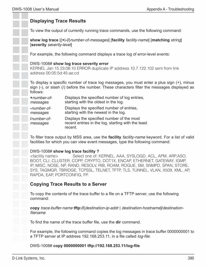
��0
DWS-1008 User’s Manual
D-Link Systems, Inc.
Appendix A - Troubleshooting
Displaying Trace Results
To view the output of currently running trace commands, use the following command:
show log trace [{+|-|/}number-of-messages] [facility facility-name] [matching string] [severity severity-level]
For example, the following command displays a trace log of error-level events:
DWS-1008# show log trace severity errorKERNEL Jan 15 23:08:10 ERROR duplicate IP address 10.7.122.102 sent from link address 00:05:5d:45:ae:cd
To display a specific number of trace log messages, you must enter a plus sign (+), minus sign (-), or slash (/) before the number. These characters filter the messages displayed as follows: +number-of-messages
Displays the specified number of log entries, starting with the oldest in the log.
-number-of-messages
Displays the specified number of entries, starting with the newest in the log.
/number-of-messages
Displays the specified number of the most recent entries in the log, starting with the least recent.
To filter trace output by MSS area, use the facility facility-name keyword. For a list of valid facilities for which you can view event messages, type the following command:
DWS-1008# show log trace facility ?<facility name> Select one of: KERNEL, AAA, SYSLOGD, ACL, APM, ARP,ASO, BOOT, CLI, CLUSTER, COPP, CRYPTO, DOT1X, ENCAP, ETHERNET, GATEWAY, IGMP, IP, MISC, NOSE, NP, RAND, RESOLV, RIB, ROAM, ROGUE, SM, SNMPD, SPAN, STORE, SYS, TAGMGR, TBRIDGE, TCPSSL, TELNET, TFTP, TLS, TUNNEL, VLAN, X509, XML, AP, RAPDA, EAP, PORTCONFIG, FP.
Copying Trace Results to a Server
To copy the contents of the trace buffer to a file on a TFTP server, use the following command:
copy trace-buffer-name tftp://[destination-ip-addr | destination-hostname]/destination-filename
To find the name of the trace buffer file, use the dir command.
For example, the following command copies the log messages in trace buffer 0000000001 to a TFTP server at IP address 192.168.253.11, in a file called log-file:
DWS-1008# copy 0000000001 tftp://192.168.253.11/log-file
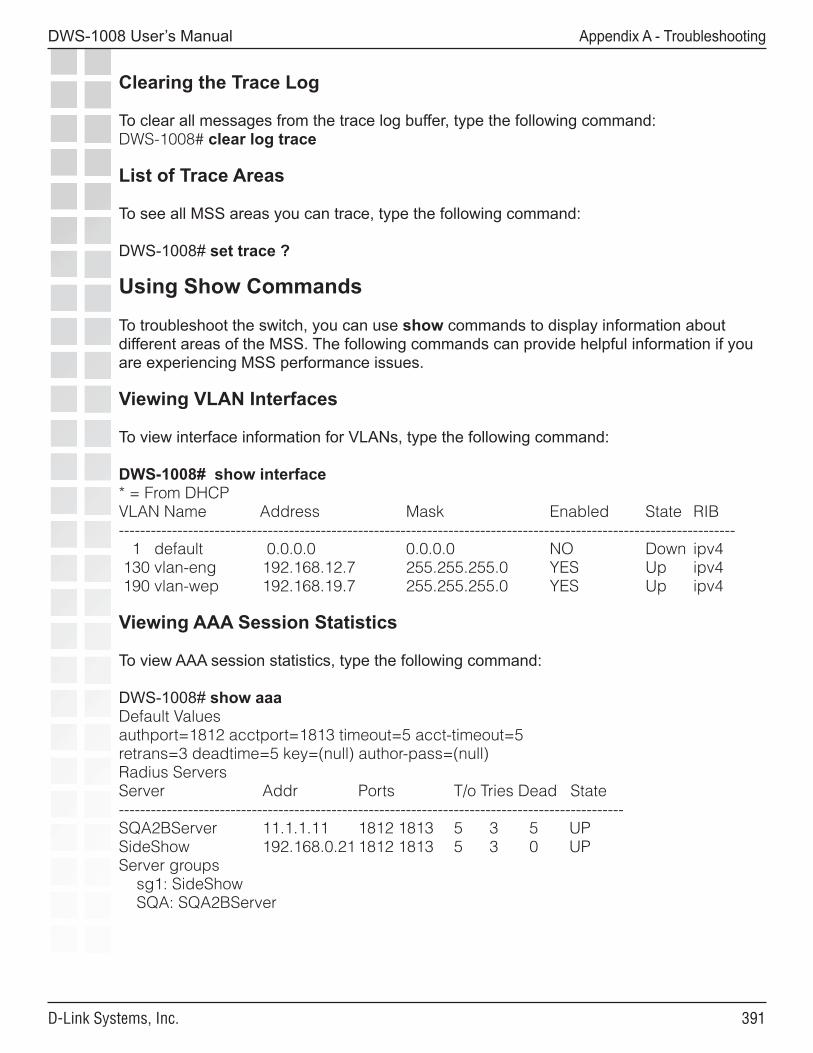
���
DWS-1008 User’s Manual
D-Link Systems, Inc.
Appendix A - Troubleshooting
Clearing the Trace Log
To clear all messages from the trace log buffer, type the following command:DWS-1008# clear log trace
List of Trace Areas
To see all MSS areas you can trace, type the following command:
DWS-1008# set trace ?
Using Show Commands
To troubleshoot the switch, you can use show commands to display information about different areas of the MSS. The following commands can provide helpful information if you are experiencing MSS performance issues.
Viewing VLAN Interfaces
To view interface information for VLANs, type the following command:
DWS-1008# show interface* = From DHCPVLAN Name Address Mask Enabled State RIB-------------------------------------------------------------------------------------------------------------------- 1 default 0.0.0.0 0.0.0.0 NO Down ipv4 130 vlan-eng 192.168.12.7 255.255.255.0 YES Up ipv4 190 vlan-wep 192.168.19.7 255.255.255.0 YES Up ipv4
Viewing AAA Session Statistics
To view AAA session statistics, type the following command:
DWS-1008# show aaaDefault Valuesauthport=1812 acctport=1813 timeout=5 acct-timeout=5retrans=3 deadtime=5 key=(null) author-pass=(null)Radius ServersServer Addr Ports T/o Tries Dead State-----------------------------------------------------------------------------------------------SQA2BServer 11.1.1.11 1812 1813 5 3 5 UPSideShow 192.168.0.21 1812 1813 5 3 0 UPServer groups sg1: SideShow SQA: SQA2BServer
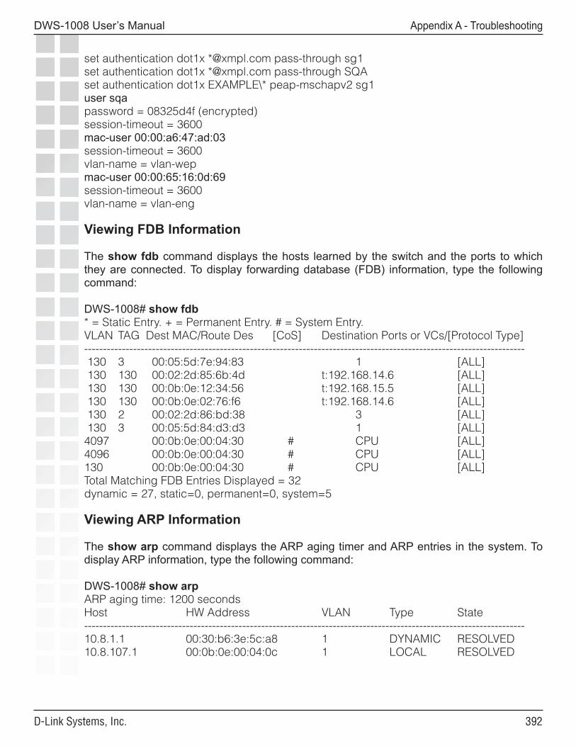
���
DWS-1008 User’s Manual
D-Link Systems, Inc.
Appendix A - Troubleshooting
set authentication dot1x *@xmpl.com pass-through sg1set authentication dot1x *@xmpl.com pass-through SQAset authentication dot1x EXAMPLE\* peap-mschapv2 sg1user sqapassword = 08325d4f (encrypted)session-timeout = 3600mac-user 00:00:a6:47:ad:03session-timeout = 3600vlan-name = vlan-wepmac-user 00:00:65:16:0d:69session-timeout = 3600vlan-name = vlan-eng
Viewing FDB Information
The show fdb command displays the hosts learned by the switch and the ports to which they are connected. To display forwarding database (FDB) information, type the following command:
DWS-1008# show fdb* = Static Entry. + = Permanent Entry. # = System Entry.VLAN TAG Dest MAC/Route Des [CoS] Destination Ports or VCs/[Protocol Type]--------------------------------------------------------------------------------------------------------------------- 130 3 00:05:5d:7e:94:83 1 [ALL] 130 130 00:02:2d:85:6b:4d t:192.168.14.6 [ALL] 130 130 00:0b:0e:12:34:56 t:192.168.15.5 [ALL] 130 130 00:0b:0e:02:76:f6 t:192.168.14.6 [ALL] 130 2 00:02:2d:86:bd:38 3 [ALL] 130 3 00:05:5d:84:d3:d3 1 [ALL]4097 00:0b:0e:00:04:30 # CPU [ALL]4096 00:0b:0e:00:04:30 # CPU [ALL]130 00:0b:0e:00:04:30 # CPU [ALL]Total Matching FDB Entries Displayed = 32dynamic = 27, static=0, permanent=0, system=5
Viewing ARP Information
The show arp command displays the ARP aging timer and ARP entries in the system. To display ARP information, type the following command:
DWS-1008# show arpARP aging time: 1200 secondsHost HW Address VLAN Type State---------------------------------------------------------------------------------------------------------------------10.8.1.1 00:30:b6:3e:5c:a8 1 DYNAMIC RESOLVED10.8.107.1 00:0b:0e:00:04:0c 1 LOCAL RESOLVED
���
DWS-1008 User’s Manual
D-Link Systems, Inc.
Appendix A - Troubleshooting
Remotely Monitoring Traffic
Remote traffic monitoring enables you to snoop wireless traffic, by using a Distributed AP as a sniffing device. The AP copies the sniffed 802.11 packets and sends the copies to an observer, which is typically a protocol analyzer such as Ethereal or Tethereal.
How Remote Traffic Monitoring Works
To monitor wireless traffic, an AP radio compares traffic sent or received on the radio to snoop filters applied to the radio by the network administrator. When an 802.11 packet matches all conditions in a filter, the AP encapsulates the packet in a Tazmen Sniffer Protocol (TZSP) packet and sends the packet to the observer host IP addresses specified by the filter. TZSP uses UDP port 37008 for its transport. (TZSP was created by Chris Waters of Network Chemistry.)
You can map up to eight snoop filters to a radio. A filter does not become active until you enable it. Filters and their mappings are persistent and remain in the configuration following a restart. However, filter state is not persistent. If the switch or the AP is restarted, the filter is disabled. To continue using the filter, you must enable it again.
Using Snoop Filters on Radios That Use Active Scan
When active scan is enabled in a radio profile, the radios that use the profile actively scan other channels in addition to the data channel that is currently in use. Active scan operates on enabled radios and disabled radios. In fact, using a disabled radio as a dedicated scanner provides better rogue detection because the radio can spend more time scanning on each channel.
When a radio is scanning other channels, snoop filters that are active on the radio also snoop traffic on the other channels. To prevent monitoring of data from other channels, use the channel option when you configure the filter, to specify the channel on which you want to scan.
All Snooped Traffic Is Sent in the Clear
Traffic that matches a snoop filter is copied after it is decrypted. The decrypted (clear) version is sent to the observer.
Best Practices for Remote Traffic Monitoring
• Do not specify an observer that is associated with the AP where the snoop filter is running. This configuration causes an endless cycle of snoop traffic.

���
DWS-1008 User’s Manual
D-Link Systems, Inc.
Appendix A - Troubleshooting
• If the snoop filter is running on a Distributed AP, and the AP used a DHCP server in its local subnet to configure its IP information, and the AP did not receive a default gateway address as a result, the observer must also be in the same subnet. Without a default gateway, the AP cannot find the observer.
• The AP that is running a snoop filter forwards snooped packets directly to the observer. This is a one-way communication, from the AP to the observer. If the observer is not present, the AP still sends the snoop packets, which use bandwidth. If the observer is present but is not listening to TZSP traffic, the observer continuously sends ICMP error indications back to the AP. These ICMP messages can affect network and AP performance.
To inform you of this condition, MSS generates a log message such as the following the first time an ICMP error message is received following the start of a snoop filter:
AP Mar 25 13:15:21.681369 ERROR DAP 3 ap_network: Observer 10.10.101.2 is not accepting TZSP packets
To prevent ICMP error messages from the observer, D-Link recommends using the Netcat application on the observer to listen to UDP packets on the TZSP port.
Configuring a Snoop Filter
To configure a snoop filter, use the following command:
set snoop filter-name [condition-list] [observer ip-addr] [snap-length num]
The filter-name can be up to 32 alphanumeric characters.
The condition-list specifies the match criteria for packets. Conditions in the list are ANDed. Therefore, to be copied and sent to an observer, a packet must match all criteria in the condition-list. You can specify up to eight of the following conditions in a filter, in any order or combination:
frame-type {eq | neq} {beacon | control | data | management | probe}channel {eq | neq} channelbssid {eq | neq} bssidsrc-mac {eq | neq} mac-addrdest-mac {eq | neq} mac-addrhost-mac {eq | neq} mac-addrmac-pair mac-addr1 mac-addr2
To match on packets to or from a specific MAC address, use the dest-mac or src-mac option. To match on both send and receive traffic for a host address, use the host-mac option. To match on a traffic flow (source and destination MAC addresses), use the mac-pair option. This option matches for either direction of a flow, and either MAC address can be the source or destination address.

���
DWS-1008 User’s Manual
D-Link Systems, Inc.
Appendix A - Troubleshooting
If you omit a condition, all packets match that condition. For example, if you omit frame-type, all frame types match the filter. For most conditions, you can use eq (equal) to match only on traffic that matches the condition value. Use neq (not equal) to match only on traffic that is not equal to the condition value.
The observer ip-addr option specifies the IP address of the station where the protocol analyzer is located. If you do not specify an observer, the AP radio still counts the packets that match the filter.
The snap-length num option specifies the maximum number of bytes to capture. If you do not specify a length, the entire packet is copied and sent to the observer. D-link recommends specifying a snap length of 100 bytes or less.
The following command configures a snoop filter named snoop1 that matches on all traffic, and copies the traffic to the device that has IP address 10.10.30.2:
DWS-1008# set snoop snoop1 observer 10.10.30.2 snap-length 100
The following command configures a snoop filter named snoop2 that matches on all data traffic between the device with MAC address aa:bb:cc:dd:ee:ff and the device with MAC address 11:22:33:44:55:66, and copies the traffic to the device that has IP address 10.10.30.3:
DWS-1008# set snoop snoop2 frame-type eq data mac-pair aa:bb:cc:dd:ee:ff 11:22:33:44:55:66 observer 10.10.30.3 snap-length 100
Displaying Configured Snoop Filters
To display the snoop filters configured on the switch, use the following command:
show snoop info [filter-name]
The following command shows the snoop filters configured in the examples above:
DWS-1008# show snoop infosnoop1: observer 10.10.30.2 snap-length 100 all packetssnoop2: observer 10.10.30.3 snap-length 100 frame-type eq data mac-pair (aa:bb:cc:dd:ee:ff, 11:22:33:44:55:66)
Editing a Snoop Filter
To edit a snoop filter, you can use the show configuration area snoop command to display the filter’s configuration command, then use cut-and-paste to reconstruct the command.Deleting a Snoop Filter
To delete a snoop filter, use the following command:
clear snoop filter-name
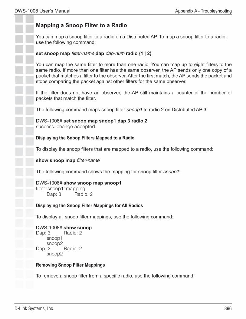
���
DWS-1008 User’s Manual
D-Link Systems, Inc.
Appendix A - Troubleshooting
Mapping a Snoop Filter to a Radio
You can map a snoop filter to a radio on a Distributed AP. To map a snoop filter to a radio, use the following command:
set snoop map filter-name dap dap-num radio {1 | 2}
You can map the same filter to more than one radio. You can map up to eight filters to the same radio. If more than one filter has the same observer, the AP sends only one copy of a packet that matches a filter to the observer. After the first match, the AP sends the packet and stops comparing the packet against other filters for the same observer.
If the filter does not have an observer, the AP still maintains a counter of the number of packets that match the filter.
The following command maps snoop filter snoop1 to radio 2 on Distributed AP 3:
DWS-1008# set snoop map snoop1 dap 3 radio 2success: change accepted.
Displaying the Snoop Filters Mapped to a Radio
To display the snoop filters that are mapped to a radio, use the following command:
show snoop map filter-name
The following command shows the mapping for snoop filter snoop1:
DWS-1008# show snoop map snoop1filter ‘snoop1’ mapping Dap: 3 Radio: 2
Displaying the Snoop Filter Mappings for All Radios
To display all snoop filter mappings, use the following command:
DWS-1008# show snoopDap: 3 Radio: 2 snoop1 snoop2Dap: 2 Radio: 2 snoop2
Removing Snoop Filter Mappings
To remove a snoop filter from a specific radio, use the following command:
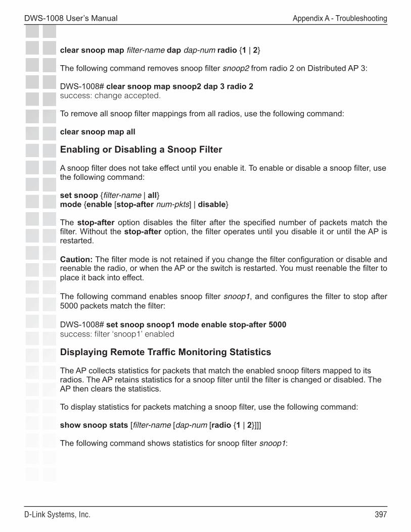
���
DWS-1008 User’s Manual
D-Link Systems, Inc.
Appendix A - Troubleshooting
clear snoop map filter-name dap dap-num radio {1 | 2}
The following command removes snoop filter snoop2 from radio 2 on Distributed AP 3:
DWS-1008# clear snoop map snoop2 dap 3 radio 2success: change accepted.
To remove all snoop filter mappings from all radios, use the following command:
clear snoop map all
Enabling or Disabling a Snoop Filter
A snoop filter does not take effect until you enable it. To enable or disable a snoop filter, use the following command:
set snoop {filter-name | all} mode {enable [stop-after num-pkts] | disable}
The stop-after option disables the filter after the specified number of packets match the filter. Without the stop-after option, the filter operates until you disable it or until the AP is restarted.
Caution: The filter mode is not retained if you change the filter configuration or disable and reenable the radio, or when the AP or the switch is restarted. You must reenable the filter to place it back into effect.
The following command enables snoop filter snoop1, and configures the filter to stop after 5000 packets match the filter:
DWS-1008# set snoop snoop1 mode enable stop-after 5000success: filter ‘snoop1’ enabled
Displaying Remote Traffic Monitoring Statistics
The AP collects statistics for packets that match the enabled snoop filters mapped to its radios. The AP retains statistics for a snoop filter until the filter is changed or disabled. The AP then clears the statistics.
To display statistics for packets matching a snoop filter, use the following command:
show snoop stats [filter-name [dap-num [radio {1 | 2}]]]
The following command shows statistics for snoop filter snoop1:
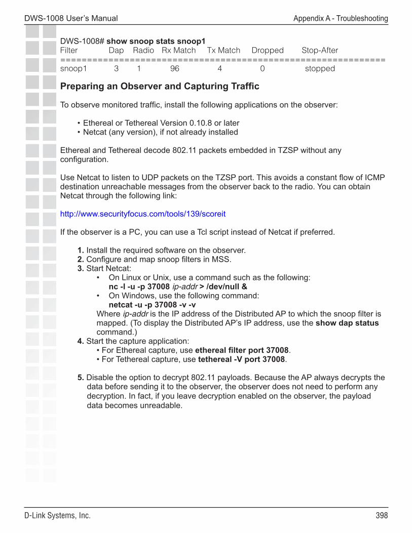
���
DWS-1008 User’s Manual
D-Link Systems, Inc.
Appendix A - Troubleshooting
DWS-1008# show snoop stats snoop1Filter Dap Radio Rx Match Tx Match Dropped Stop-After=============================================================snoop1 3 1 96 4 0 stopped
Preparing an Observer and Capturing Traffic
To observe monitored traffic, install the following applications on the observer:
• Ethereal or Tethereal Version 0.10.8 or later• Netcat (any version), if not already installed
Ethereal and Tethereal decode 802.11 packets embedded in TZSP without any configuration.
Use Netcat to listen to UDP packets on the TZSP port. This avoids a constant flow of ICMP destination unreachable messages from the observer back to the radio. You can obtain Netcat through the following link:
http://www.securityfocus.com/tools/139/scoreit
If the observer is a PC, you can use a Tcl script instead of Netcat if preferred.
1. Install the required software on the observer.2. Configure and map snoop filters in MSS.3. Start Netcat:
• On Linux or Unix, use a command such as the following: nc -l -u -p 37008 ip-addr > /dev/null &
• On Windows, use the following command: netcat -u -p 37008 -v -v
Where ip-addr is the IP address of the Distributed AP to which the snoop filter is mapped. (To display the Distributed AP’s IP address, use the show dap status command.)
4. Start the capture application:• For Ethereal capture, use ethereal filter port 37008. • For Tethereal capture, use tethereal -V port 37008.
5. Disable the option to decrypt 802.11 payloads. Because the AP always decrypts the data before sending it to the observer, the observer does not need to perform any decryption. In fact, if you leave decryption enabled on the observer, the payload data becomes unreadable.
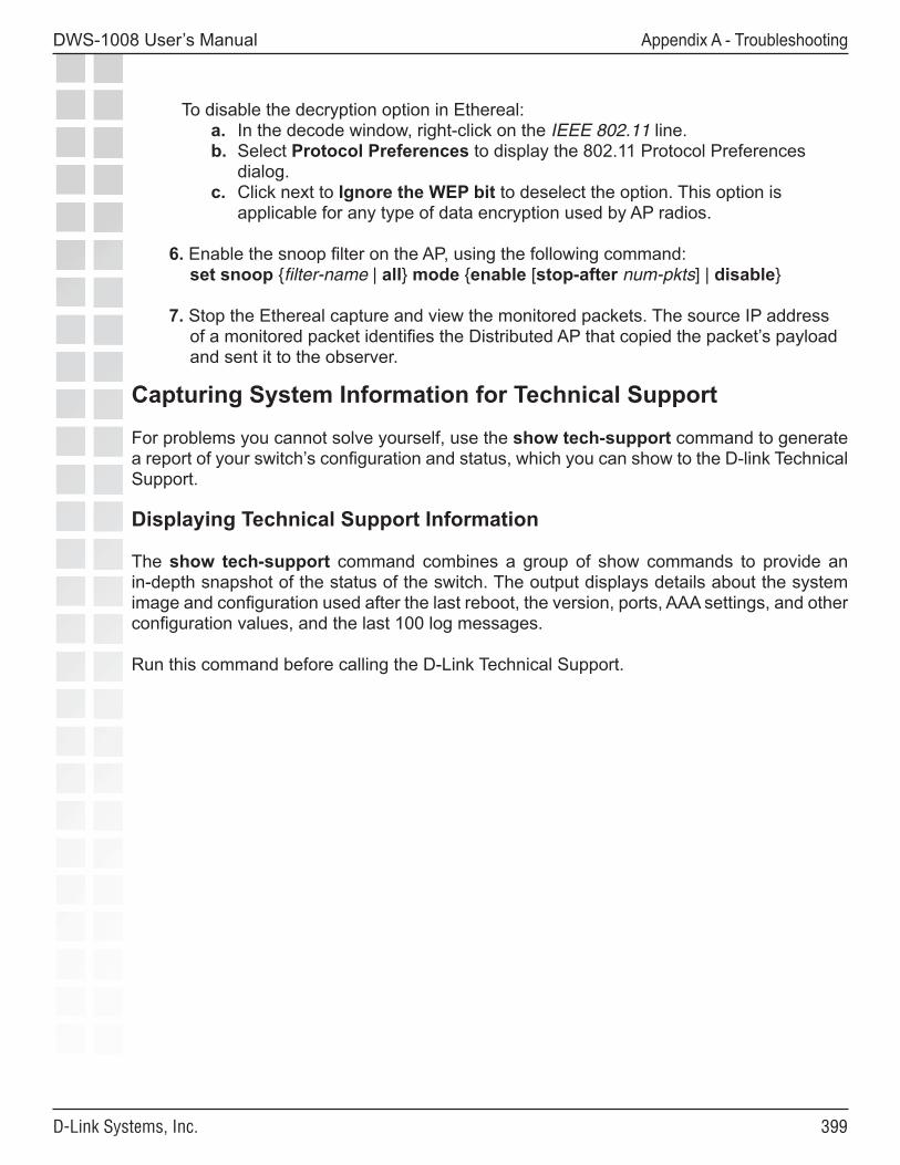
���
DWS-1008 User’s Manual
D-Link Systems, Inc.
Appendix A - Troubleshooting
To disable the decryption option in Ethereal:a. In the decode window, right-click on the IEEE 802.11 line.b. Select Protocol Preferences to display the 802.11 Protocol Preferences
dialog.c. Click next to Ignore the WEP bit to deselect the option. This option is
applicable for any type of data encryption used by AP radios.
6. Enable the snoop filter on the AP, using the following command: set snoop {filter-name | all} mode {enable [stop-after num-pkts] | disable}
7. Stop the Ethereal capture and view the monitored packets. The source IP address of a monitored packet identifies the Distributed AP that copied the packet’s payload and sent it to the observer.
Capturing System Information for Technical Support
For problems you cannot solve yourself, use the show tech-support command to generate a report of your switch’s configuration and status, which you can show to the D-link Technical Support.
Displaying Technical Support Information
The show tech-support command combines a group of show commands to provide an in-depth snapshot of the status of the switch. The output displays details about the system image and configuration used after the last reboot, the version, ports, AAA settings, and other configuration values, and the last 100 log messages.
Run this command before calling the D-Link Technical Support.
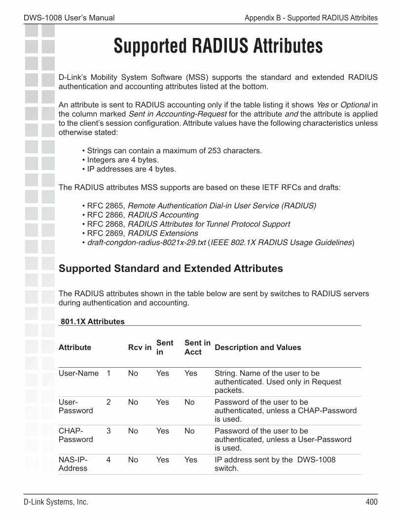
�00
DWS-1008 User’s Manual
D-Link Systems, Inc.
Appendix B - Supported RADIUS Attribites
Supported RADIUS AttributesD-Link’s Mobility System Software (MSS) supports the standard and extended RADIUS authentication and accounting attributes listed at the bottom.
An attribute is sent to RADIUS accounting only if the table listing it shows Yes or Optional in the column marked Sent in Accounting-Request for the attribute and the attribute is applied to the client’s session configuration. Attribute values have the following characteristics unless otherwise stated:
• Strings can contain a maximum of 253 characters.• Integers are 4 bytes.• IP addresses are 4 bytes.
The RADIUS attributes MSS supports are based on these IETF RFCs and drafts:
• RFC 2865, Remote Authentication Dial-in User Service (RADIUS)• RFC 2866, RADIUS Accounting• RFC 2868, RADIUS Attributes for Tunnel Protocol Support• RFC 2869, RADIUS Extensions• draft-congdon-radius-8021x-29.txt (IEEE 802.1X RADIUS Usage Guidelines)
Supported Standard and Extended Attributes
The RADIUS attributes shown in the table below are sent by switches to RADIUS servers during authentication and accounting.
801.1X Attributes
Attribute Rcv in Sent in
Sent in Acct Description and Values
User-Name 1 No Yes Yes String. Name of the user to be authenticated. Used only in Request packets.
User-Password
2 No Yes No Password of the user to be authenticated, unless a CHAP-Password is used.
CHAP- Password
3 No Yes No Password of the user to be authenticated, unless a User-Password is used.
NAS-IP- Address
4 No Yes Yes IP address sent by the DWS-1008 switch.
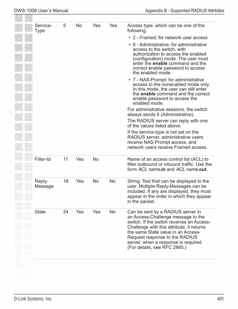
�0�
DWS-1008 User’s Manual
D-Link Systems, Inc.
Appendix B - Supported RADIUS Attribites
Service-Type
5 No Yes Yes Access type, which can be one of the following: • 2 - Framed; for network user access • 6 - Administrative; for administrative
access to the switch, with authorization to access the enabled (configuration) mode. The user must enter the enable command and the correct enable password to access the enabled mode.
• 7 - NAS-Prompt; for administrative access to the nonenabled mode only. In this mode, the user can still enter the enable command and the correct enable password to access the enabled mode.
For administrative sessions, the switch always sends 6 (Administrative). The RADIUS server can reply with one of the values listed above.If the service-type is not set on the RADIUS server, administrative users receive NAS-Prompt access, and network users receive Framed access.
Filter-Id 11 Yes No Name of an access control list (ACL) to filter outbound or inbound traffic. Use the form ACL name.in and ACL name.out.
Reply- Message
18 Yes No No String. Text that can be displayed to the user. Multiple Reply-Messages can be included. If any are displayed, they must appear in the order in which they appear in the packet.
State 24 Yes Yes No Can be sent by a RADIUS server in an Access-Challenge message to the switch. If the switch receives an Access-Challenge with this attribute, it returns the same State value in an Access-Request response to the RADIUS server, when a response is required. (For details, see RFC 2865.)
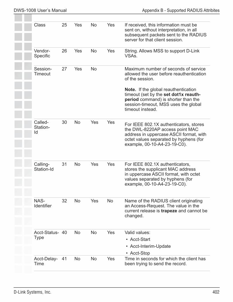
�0�
DWS-1008 User’s Manual
D-Link Systems, Inc.
Appendix B - Supported RADIUS Attribites
Class 25 Yes No Yes If received, this information must be sent on, without interpretation, in all subsequent packets sent to the RADIUS server for that client session.
Vendor- Specific
26 Yes No Yes String. Allows MSS to support D-Link VSAs.
Session- Timeout
27 Yes No Maximum number of seconds of service allowed the user before reauthentication of the session.
Note. If the global reauthentication timeout (set by the set dot1x reauth-period command) is shorter than the session-timeout, MSS uses the global timeout instead.
Called-Station- Id
30 No Yes Yes For IEEE 802.1X authenticators, stores the DWL-8220AP access point MAC address in uppercase ASCII format, with octet values separated by hyphens (for example, 00-10-A4-23-19-C0).
Calling-Station-Id
31 No Yes Yes For IEEE 802.1X authenticators, stores the supplicant MAC address in uppercase ASCII format, with octet values separated by hyphens (for example, 00-10-A4-23-19-C0).
NAS-Identifier
32 No Yes No Name of the RADIUS client originating an Access-Request. The value in the current release is trapeze and cannot be changed.
Acct-Status- Type
40 No No Yes Valid values: • Acct-Start • Acct-Interim-Update • Acct-Stop
Acct-Delay- Time
41 No No Yes Time in seconds for which the client has been trying to send the record.
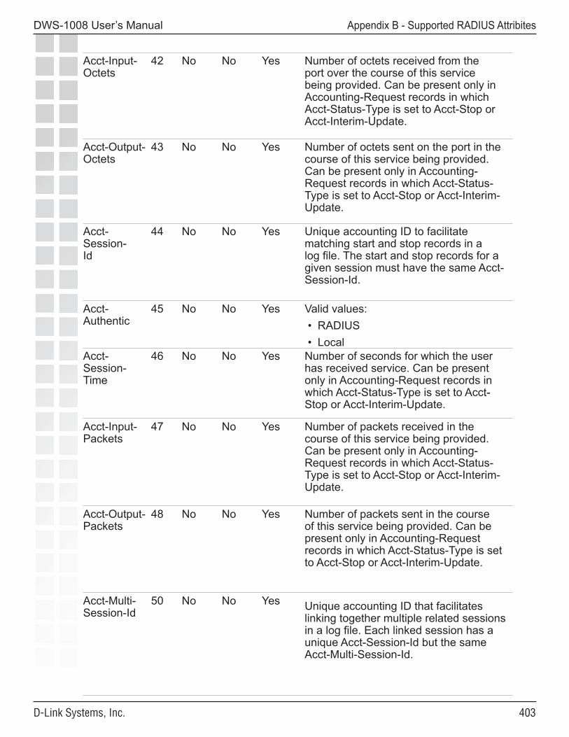
�0�
DWS-1008 User’s Manual
D-Link Systems, Inc.
Appendix B - Supported RADIUS Attribites
Acct-Input- Octets
42 No No Yes Number of octets received from the port over the course of this service being provided. Can be present only in Accounting-Request records in which Acct-Status-Type is set to Acct-Stop or Acct-Interim-Update.
Acct-Output- Octets
43 No No Yes Number of octets sent on the port in the course of this service being provided. Can be present only in Accounting-Request records in which Acct-Status-Type is set to Acct-Stop or Acct-Interim-Update.
Acct-Session- Id
44 No No Yes Unique accounting ID to facilitate matching start and stop records in a log file. The start and stop records for a given session must have the same Acct-Session-Id.
Acct-Authentic
45 No No Yes Valid values: • RADIUS • Local
Acct-Session- Time
46 No No Yes Number of seconds for which the user has received service. Can be present only in Accounting-Request records in which Acct-Status-Type is set to Acct-Stop or Acct-Interim-Update.
Acct-Input- Packets
47 No No Yes Number of packets received in the course of this service being provided. Can be present only in Accounting-Request records in which Acct-Status-Type is set to Acct-Stop or Acct-Interim-Update.
Acct-Output- Packets
48 No No Yes Number of packets sent in the course of this service being provided. Can be present only in Accounting-Request records in which Acct-Status-Type is set to Acct-Stop or Acct-Interim-Update.
Acct-Multi- Session-Id
50 No No Yes Unique accounting ID that facilitates linking together multiple related sessions in a log file. Each linked session has a unique Acct-Session-Id but the same Acct-Multi-Session-Id.
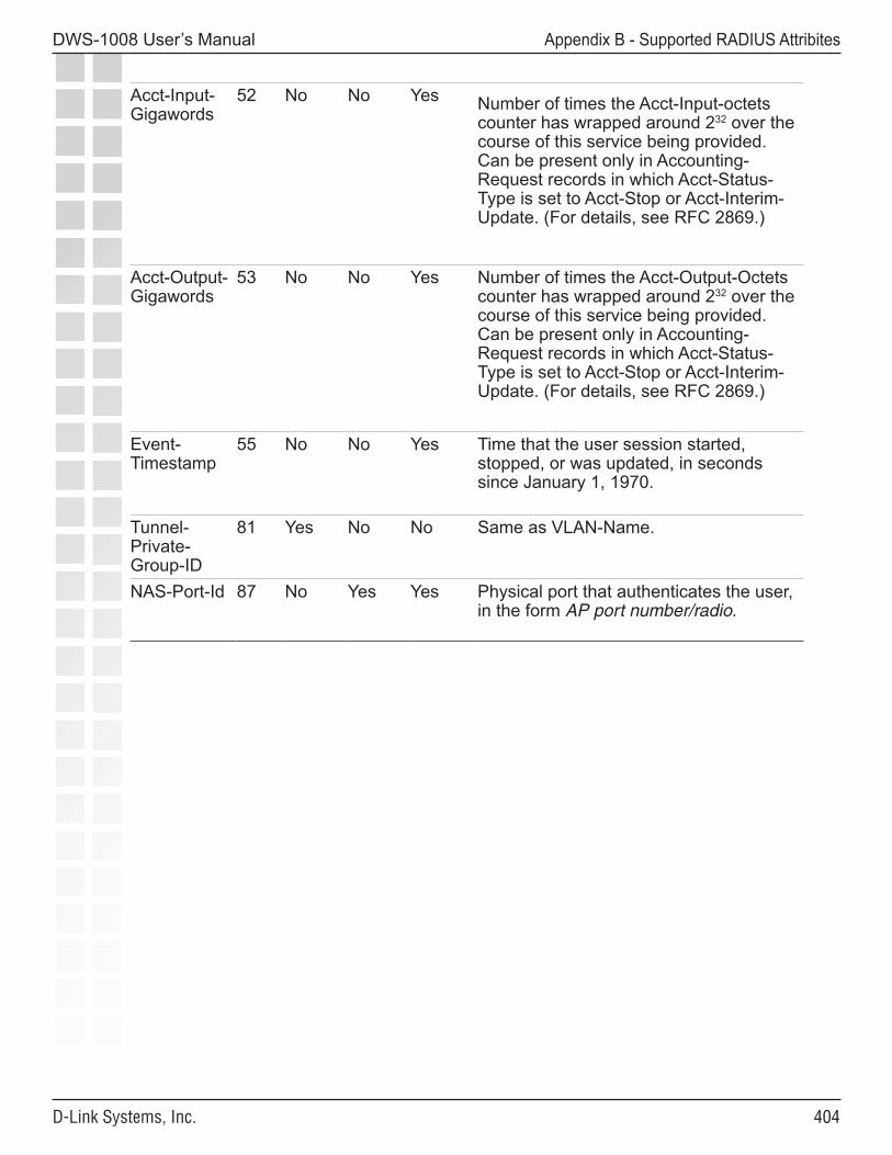
�0�
DWS-1008 User’s Manual
D-Link Systems, Inc.
Appendix B - Supported RADIUS Attribites
Acct-Input- Gigawords
52 No No Yes Number of times the Acct-Input-octets counter has wrapped around 232 over the course of this service being provided. Can be present only in Accounting-Request records in which Acct-Status-Type is set to Acct-Stop or Acct-Interim-Update. (For details, see RFC 2869.)
Acct-Output- Gigawords
53 No No Yes Number of times the Acct-Output-Octets counter has wrapped around 232 over the course of this service being provided. Can be present only in Accounting-Request records in which Acct-Status-Type is set to Acct-Stop or Acct-Interim-Update. (For details, see RFC 2869.)
Event- Timestamp
55 No No Yes Time that the user session started, stopped, or was updated, in seconds since January 1, 1970.
Tunnel- Private-Group-ID
81 Yes No No Same as VLAN-Name.
NAS-Port-Id 87 No Yes Yes Physical port that authenticates the user, in the form AP port number/radio.
�0�
DWS-1008 User’s Manual
D-Link Systems, Inc.
Appendix C - DHCP Server
DHCP ServerMSS has a DHCP server that the switch uses to allocate IP addresses to the following:
• Directly connected APs
DHCP service is enabled by default.
Optionally, you can configure the DHCP server to also provide IP addresses to Distributed APs and to clients.
Configuration is supported on an individual VLAN basis. When you configure the DHCP server on a VLAN, the server can serve addresses only from the subnet that contains the host address assigned to the VLAN. By default, the VLAN can serve any unused address in the subnet except the VLAN’s host address and the network and broadcast addresses. You can specify the address range.
You can configure the DHCP server on more than one VLAN. You can configure a DHCP client and DHCP server on the same VLAN, but only the client or the server can be enabled. The DHCP client and DHCP server cannot both be enabled on the same VLAN at the same time.
The MSS DHCP server is implemented according to “RFC 2131: Dynamic Host Configuration Protocol” and “RFC 2132: DHCP Options and BOOTP Vendor Extensions”, with the following exceptions:
• If the switch is powered down or restarted, MSS does not retain address allocations or lease times.
• The MSS DHCP server will not operate properly when another DHCP server is present on the same subnet.
• The MSS DHCP server is configurable on an individual VLAN basis only, and operates only on the subnets for which you configure it.
Note: Use of the MSS DHCP server to allocate client addresses is intended for temporary, demonstration deployments and not for production networks. D-Link recommends that you do not use the MSS DHCP server to allocate client addresses in a production network.
�0�
DWS-1008 User’s Manual
D-Link Systems, Inc.
Appendix C - DHCP Server
How the MSS DHCP Server Works
When MSS receives a DHCP Discover packet, the DHCP server allocates an address from the configured range according to RFC 2131 and ARPs the address to ensure that it is not already in use. If the address is in use, the server allocates the next address in the range, and ARPs again. The process continues until MSS finds an address that is not in use. MSS then offers the address to the Distributed AP or client that sent the DHCP Discover. If there are no unused addresses left in the range, MSS ignores the DHCP Discover and generates a log message.
If the client does not respond to the DHCP Offer from the MSS DHCP server within 2 minutes, the offer becomes invalid and MSS returns the address to the pool.
The siaddr value in the DHCP exchanges is the IP address of the VLAN. The yiaddr value is an unused address within the range the server is allowed to use.
In addition to an IP address, the Offer message from the MSS DHCP server also contains the following options:
• Option 54 - Server Identifier, which has the same value as siaddr.
• Option 51 - Address Lease, which is 12 hours and cannot be configured.
• Option 1 - Subnet Mask of the VLAN’s IP interface.
• Option 15 - Domain Name, which is the default domain name configured on the switch. If the default domain name is not configured, this option is blank.
• Option 3 - Router. If the IP route table contains a default route with an address in the subnet configured on the VLAN, then the server specifies this address. Otherwise, the server does not specify a router address.
• Option 6 - Domain Name Server, which is a list of the DNS server IP addresses configured on the switch. If no DNS servers are configured on the switch, this option is blank.
Configuring the DHCP Server
You can configure the DHCP server on an individual VLAN basis. To configure the server, use the following command:
set interface vlan-id ip dhcp-server [enable | disable] [start ip-addr1 stop ip-addr2]
The vlan-id can be the VLAN name or number. The start ip-addr1 and stop ip-addr2 options specify the beginning and ending addresses of the address range (also called the address pool). By default, all addresses except the host address of the VLAN, the network broadcast address, and the subnet broadcast address are included in the range. If you specify the range, the start address must be lower than the stop address, and all addresses must be in the same subnet. The IP interface of the VLAN must be within the same subnet but is not required to be within the range.
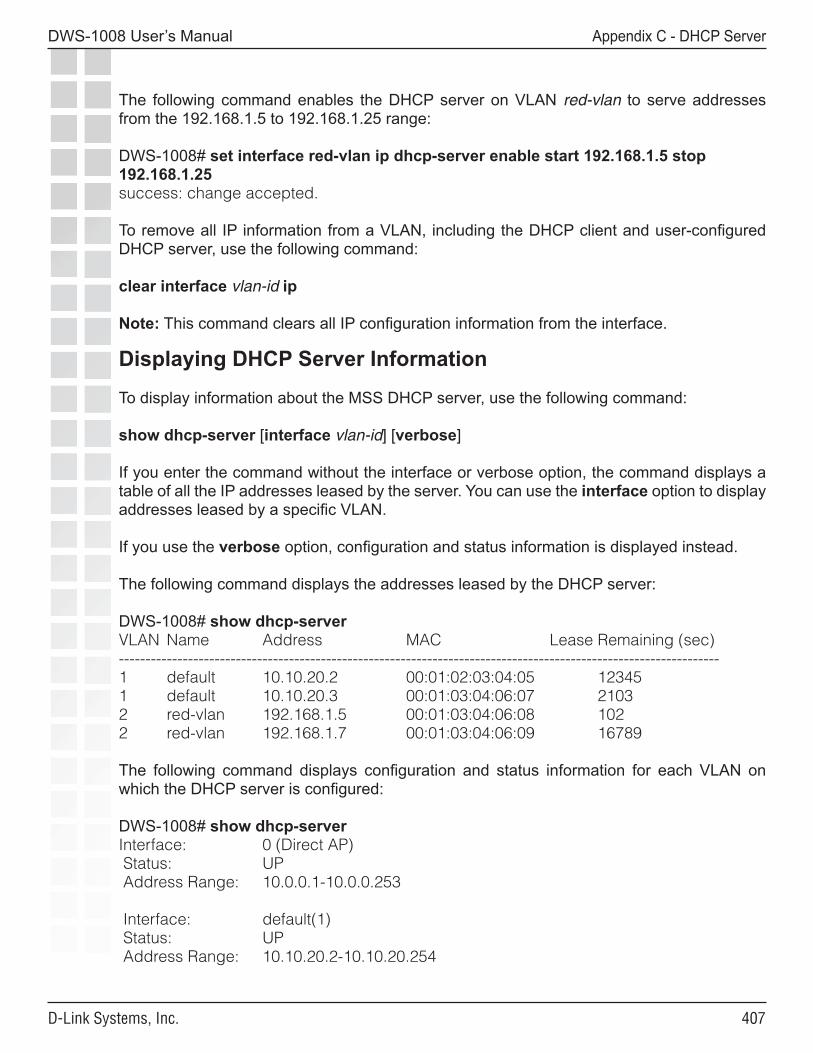
�0�
DWS-1008 User’s Manual
D-Link Systems, Inc.
Appendix C - DHCP Server
The following command enables the DHCP server on VLAN red-vlan to serve addresses from the 192.168.1.5 to 192.168.1.25 range:
DWS-1008# set interface red-vlan ip dhcp-server enable start 192.168.1.5 stop 192.168.1.25success: change accepted.
To remove all IP information from a VLAN, including the DHCP client and user-configured DHCP server, use the following command:
clear interface vlan-id ip
Note: This command clears all IP configuration information from the interface.
Displaying DHCP Server Information
To display information about the MSS DHCP server, use the following command:
show dhcp-server [interface vlan-id] [verbose]
If you enter the command without the interface or verbose option, the command displays a table of all the IP addresses leased by the server. You can use the interface option to display addresses leased by a specific VLAN.
If you use the verbose option, configuration and status information is displayed instead.
The following command displays the addresses leased by the DHCP server:
DWS-1008# show dhcp-serverVLAN Name Address MAC Lease Remaining (sec)-----------------------------------------------------------------------------------------------------------------1 default 10.10.20.2 00:01:02:03:04:05 12345 1 default 10.10.20.3 00:01:03:04:06:07 21032 red-vlan 192.168.1.5 00:01:03:04:06:08 1022 red-vlan 192.168.1.7 00:01:03:04:06:09 16789
The following command displays configuration and status information for each VLAN on which the DHCP server is configured:
DWS-1008# show dhcp-serverInterface: 0 (Direct AP) Status: UP Address Range: 10.0.0.1-10.0.0.253
Interface: default(1) Status: UP Address Range: 10.10.20.2-10.10.20.254
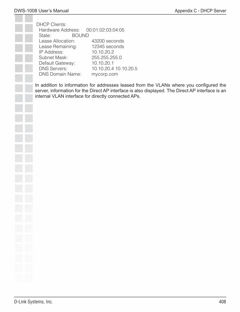
�0�
DWS-1008 User’s Manual
D-Link Systems, Inc.
Appendix C - DHCP Server
DHCP Clients: Hardware Address: 00:01:02:03:04:05 State: BOUND Lease Allocation: 43200 seconds Lease Remaining: 12345 seconds IP Address: 10.10.20.2 Subnet Mask: 255.255.255.0 Default Gateway: 10.10.20.1 DNS Servers: 10.10.20.4 10.10.20.5 DNS Domain Name: mycorp.com
In addition to information for addresses leased from the VLANs where you configured the server, information for the Direct AP interface is also displayed. The Direct AP interface is an internal VLAN interface for directly connected APs.
�0�
DWS-1008 User’s Manual
D-Link Systems, Inc.
Appendix D - Glossary
Glossary3DES
A three-round application of the Data Encryption Standard (DES) that uses a 168-bit encryption key. See also DES.
802.1D
The IEEE LAN specification for the operation of media access control (MAC) bridges.
802.1p
An IEEE LAN standard method for classifying packets in bridged virtual LANs (VLANs). As part of 802.1Q protocol, 802.1p defines a field in the VLAN tag of a frame header that provides class-of-service (CoS) definitions at Layer 2. See also 802.1Q.
802.1Q
The IEEE LAN standard that defines a protocol for filtering and forwarding services at Layer 2. Ethernet frames are directed by means of a tag inserted into the frame header. A virtual LAN (VLAN) identifier (VID) field in the tag identifies the VLAN with which the frame is associated.
802.1X
The primary IEEE standard for port-based network access control. The 802.1X standard, which is based on the Extensible Authentication Protocol (EAP), provides an authentication framework that supports a variety of methods for authenticating and authorizing network access for wired or wireless users. See also EAP; EAPTLS; PEAP; TLS; TTLS.
802.2
An IEEE LAN specification that defines the logical link control (LLC) sublayer, the upper portion of the Data Link layer. LLC encapsulation can be used by any lower-layer LAN technology. Compare 802.3; Ethernet II.
802.3
An IEEE LAN specification for a Carrier Sense Multiple Access with Collision Detection (CSMA-CD) network, a type of network related to Ethernet. In general, 802.3 specifies the physical media and the working characteristics of LANs. An 802.3 frame uses source and destination media access control (MAC) addresses to identify its originator and receiver (or receivers). Compare 802.2; Ethernet II.
802.3z
An extension to the IEEE 802.3 LAN specification, describing gigabit Ethernet (1000 Mbps) transmission. The extension includes specifications for the media access control (MAC), physical layer, repeater, and management characteristics of gigabit Ethernet.
��0
DWS-1008 User’s Manual
D-Link Systems, Inc.
Appendix D - Glossary
802.11
An IEEE LAN specification that defines the mobile (wireless) network access link layer. The specification includes the 802.11 media access control (MAC) sublayer of the Data Link layer, and two sublayers of the Physical (PHY) layer—a frequency-hopping spread-spectrum (FHSS) physical layer and a direct-sequence spread-spectrum (DSSS) link layer. Later additions to 802.11 include additional physical layers. See also 802.11a; 802.11b; 802.11g; 802.11i.
802.11a
A supplement to the IEEE 802.11 wireless LAN (WLAN) specification, describing transmission through the Physical layer (PHY) based on orthogonal frequency division multiplexing (OFDM), at a frequency of 5 GHz and data rates of up to 54 Mbps.
802.11b
A supplement to the IEEE 802.11 wireless LAN (WLAN) specification, describing transmission through the Physical layer (PHY) based on direct-sequence spread-spectrum (DSSS), at a frequency of 2.4 GHz and data rates of up to 11 Mbps.
802.11b/g radio
A radio that can receive and transmit signals at IEEE 802.11b and 802.11g data rates. D-Link 802.11b/g radios allow associations from 802.11b clients as well as 802.11g clients by default, for networks that have a mixture of both client types. However, association by any 802.11b clients restricts the maximum data transmit rate for all clients. To allow the radios to operate at the higher 802.11g data rates, you can set 802.11b/g radios to reject association attempts by 802.11b clients.
802.11g
A supplement to the IEEE 802.11 wireless LAN (WLAN) specification, describing transmission through the Physical layer (PHY) based on orthogonal frequency division multiplexing (OFDM), at a frequency of 2.4 GHz and data rates of up to 54 Mbps.
802.11i
A draft supplement to the IEEE 802.11 wireless LAN (WLAN) specification, for enhanced security through the use of stronger encryption protocols such as the Temporal Key Integrity Protocol (TKIP) and AES Counter Mode with Cipher Block Chaining Message Authentication Code Protocol (AES-CCMP). These protocols provide replay protection, cryptographically keyed integrity checks, and key derivation based on the IEEE 802.1X port authentication standard. See also AES; CCMP; TKIP; WPA.
AAA
Authentication, authorization, and accounting. A framework for configuring services that provide a secure network connection and a record of user activity, by identifying who the user is, what the user can access, and what services and resources the user is consuming. The DWS-1008 switch can use a RADIUS server or its own local database for AAA services.
access control entry
See ACE.
���
DWS-1008 User’s Manual
D-Link Systems, Inc.
Appendix D - Glossary
access control list
See security ACL.
access point (AP)
A hardware unit that acts as a communication hub by linking wireless mobile IEEE 802.11 stations such as PCs to a wired backbone network. A D-Link Mobility System has DWL-8220AP access points. See also ad hoc network; infrastructure network.
ACE
A rule in a security access control list (ACL) that grants or denies a set of network access rights based on one or more criteria. ACEs use criteria such as a protocol and a source or destination IP address to determine whether to permit or deny packets that match the criteria. ACEs are processed in the order in which they appear in the security ACL. See also security ACL.
ACL
See security ACL.
ad hoc network
One of two IEEE 802.11 network frameworks. In an ad hoc network, a set of wireless stations communicate directly with one another without using an access point (AP) or any connection to a wired network. With an ad hoc network, also known as a peer-to-peer network or independent basic service set (IBSS), you can set up a wireless network in which a wireless infrastructure does not exist or is not required for services (in a classroom, for example), or through which access to the wired network is prevented (for consultants at a client site, for example). Compare infrastructure network.
Advanced Encryption Standard
See AES.
AES
Advanced Encryption Standard. One of the Federal Information Processing Standards (FIPS). The AES, documented in FIPS Publication 197, specifies a symmetric encryption algorithm for use by organizations to protect sensitive information. See 802.11i; CCMP.
AP
See access point (AP).
association
The process defined in IEEE 802.11 by which an authenticated mobile (wireless) station establishes a relationship with a wireless access point (AP) to gain full network access. The access point assigns the mobile station an association identifier (AID), which the wireless LAN (WLAN) uses to track the mobile station as it roams. After associating with a DWL-8220AP access point in a D-Link Mobility System, a mobile station can send and receive traffic through any DWL-8220AP access point that’s connected to the same DWS-1008.
���
DWS-1008 User’s Manual
D-Link Systems, Inc.
Appendix D - Glossary
attribute
In authentication, authorization, and accounting (AAA), a property used to identify (authenticate) a user or to configure (authorize) or record (account for) a user’s administrative or network session. A user’s AAA attributes are stored in a user profile in the local database on a DWS-1008 switch, or on a RADIUS server. Attribute names are casesensitive. See also RADIUS; VSA.
authenticated identity
In a D-Link network, the correspondence established between a user and his or her authentication attributes. User authentication attributes are linked to the user, rather than to a physical port or device, regardless of the user’s location or type of network connection. Because the authenticated identity follows the user, he or she requires no reauthentication when roaming.
authentication, authorization, and accounting
See AAA.
authentication mobility
The ability of a user (client) authenticated via Extensible Authentication Protocol (EAP)—plus an appropriate subprotocol and back-end authentication, authorization, and accounting (AAA) service—to roam to different access points (APs) without reauthentication.
authentication server
An entity that provides an authentication service to an authenticator. From the credentials provided by a client (or supplicant), the authentication service determines whether the supplicant is authorized to access the services of the authenticator. In a D-Link network, one or more RADIUS servers can act as authentication servers.
authenticator
A device that authenticates a client.
basic service set
See BSS.
basic service set identifier
See BSSID.
bias
The priority of one DWS-1008 switch over other switches for booting, configuring, and providing data transfer for a DWL-8220AP access point. Bias can be set to either low or high on each DWS-1008 switch and is high by default. Bias applies only to switches that are indirectly attached to the AP through an intermediate Layer 2 or Layer 3 network. An AP always attempts to boot on AP port 1 first, and if the AP is directly attached to a switch on AP port 1, the AP uses the directly attached switch to boot from regardless of the bias settings. See also dual-homed connection.
���
DWS-1008 User’s Manual
D-Link Systems, Inc.
Appendix D - Glossary
BSS
Basic service set. A set of wireless stations that communicate with one another through an access point (AP).
BSSID
Basic service set identifier. The 48-bit media access control (MAC) address of the radio in the access point (AP) that serves the stations in a basic service set (BSS).
CA
See certificate authority (CA).
CBC-MAC
See CCMP.
CCI
Co-channel interference. Obstruction that occurs when one signal on a particular frequency intrudes into a cell that is using that same frequency for transmission. In multicell networks, systems are designed to minimize CCI through appropriate transmission power and channel selection.
CCMP
Counter-Mode with Cipher Block Chaining Message Authentication Code Protocol. A wireless encryption protocol based on the Advanced Encryption Standard (AES) and defined in the IEEE 802.11i specification. CCMP uses a symmetric key block cipher mode that provides privacy by means of counter mode and data origin authenticity by means of cipher block chaining message authentication code (CBC-MAC). See also 802.11i; AES; TKIP; WPA. Compare WEP.
cell
The geographical area covered by a wireless transmitter.
certificate authority (CA)
Network software that issues and manages security credentials and public keys for authentication and message encryption. As part of a public-key infrastructure (PKI), which enables secure exchanges of information over a network, a certificate authority checks with a registration authority (RA) to verify information provided by the requestor of a digital certificate. If the registration authority verifies the requestor’s information, the certificate authority can issue a certificate. Based on the PKI implementation, the certificate content can include the certificate’s expiration date, the owner’s public key, the owner’s name, and other information about the public-key owner. See also registration authority (RA).
Certificate Signing Request
See CSR.
���
DWS-1008 User’s Manual
D-Link Systems, Inc.
Appendix D - Glossary
Challenge Handshake Authentication Protocol
See CHAP.
CHAP
Challenge Handshake Authentication Protocol. An authentication protocol that defines a threeway handshake to authenticate a user (client). CHAP uses the MD5 hash algorithm to generate a response to a challenge that can be checked by the authenticator. For wireless connections, CHAP is not secure and must be protected by the cryptography in such authentication methods as the Protected Extensible Authentication Protocol (PEAP) and Tunneled Transport Layer Security (TTLS).
client
The requesting program or device in a client-server relationship. In a wireless LAN (WLAN), the client (or supplicant) requests access to the services provided by the authenticator. See also supplicant.
co-channel interference
See CCI.
collision domain
A single half-duplex IEEE 802.3 Carrier Sense Multiple Access with Collision Detection (CSMA-CD) network. A collision occurs when two or more Layer 2 devices in the network transmit at the same time. Ethernet segments separated by a Layer 2 switch are within different collision domains.
comma-separated values file
See CSV file.
communications plenum cable
See plenum-rated cable.
CPC
Communications plenum cable. See plenum-rated cable.
CRC
Cyclic redundancy check. A primitive message integrity check.
crypto
See cryptography.
���
DWS-1008 User’s Manual
D-Link Systems, Inc.
Appendix D - Glossary
cryptography
The science of information security. Modern cryptography is typically concerned with the processes of scrambling ordinary text (known as plain text or clear text) into encrypted text at the sender’s end of a connection, and decrypting the encrypted text back into clear text at the receiver’s end. Because its security is independent of the channels through which the text passes, cryptography is the only way of protecting communications over channels that are not under the user’s control. The goals of cryptography are confidentiality, integrity, nonrepudiation, and authentication. The encrypted information cannot be understood by anyone for whom it is not intended, or altered in storage or transmission without the alteration being detected. The sender cannot later deny the creation or transmission of the information, and the sender and receiver can confirm each other’s identity and the information’s origin and destination.
CSR
Certificate Signing Request. A message sent by an administrator to request a security certificate from a certificate authority (CA). A CSR is a text string formatted by Privacy Enhanced Mail (PEM) protocol according to Public Key Cryptography Standard (PKCS) #10. The CSR contains the information needed by the certificate authority to generate the certificate.
CSV file
Comma-separated values file. A text file that displays tabular data in a comma-delimited format, as a list of rows in which each column’s value is separated from the next by a comma. A CSV file is useful for transferring data between database applications.
cyclic redundancy check
See CRC.
dBm
Decibels referred to 1 milliwatt (mW). A measurement of relative power related to 1 mW. For example, 20 dBm corresponds to 1020 dBm/10 = 100 mW.
decibels referred to 1 milliwatt (mW).
See dBm.
Data Encryption Standard
See DES.
delivery traffic indication map
See DTIM.
DES
Data Encryption Standard. A federally approved symmetric encryption algorithm in use for many years and replaced by the Advanced Encryption Standard (AES). See also 3DES.
���
DWS-1008 User’s Manual
D-Link Systems, Inc.
Appendix D - Glossary
DHCP
Dynamic Host Configuration Protocol. A protocol that dynamically assigns IP addresses to stations, from a centralized server. DHCP is the successor to the Bootstrap Protocol (BOOTP).
dictionary attack
An attempt to gain illegal access to a computer or network by logging in repeatedly with passwords that are based on a list of terms in a dictionary.
Diffie-Hellman
A key exchange algorithm that was the first public-key algorithm ever published. Diffie-Hellman can be used anonymously (without authentication).
Diffserv
Differentiated services. An architecture for providing different types or levels of service for network traffic. Diffserv aggregates flows in the network so that routers and switches need to distinguish only a relatively small number of aggregated flows, even if those flows contain thousands or millions of individual flows.
digital certificate
A document containing the name of a user (client) or server, a digital signature, a public key, and other elements used in authentication and encryption. See also X.509.
digital signature
The result of encrypting a hash of a message or document with a private key. A digital signature is used to verify the authenticity of the sender and the integrity (unaltered condition) of the message or document. See also hash.
Digital Signature Algorithm
See DSA.
direct-sequence spread-spectrum
See DSSS.
domain
(1) On the Internet, a set of network addresses that are organized in levels. (2) In Microsoft Windows NT and Windows 2000, a set of network resources (applications, printers, and so forth) for a group of users (clients). Clients log into the domain to access the resources, which can be located on a number of different servers in the network.
DSA
Digital Signature Algorithm. The public-key algorithm used to sign X.509 certificates.
���
DWS-1008 User’s Manual
D-Link Systems, Inc.
Appendix D - Glossary
DSSS
Direct-sequence spread-spectrum. One of two types of spread-spectrum radio technology used in wireless LAN (WLAN) transmissions. To increase a data signal’s resistance to interference, the signal at the sending station is combined with a higher-rate bit sequence that spreads the user data in frequency by a factor equal to the spreading ratio. Compare FHSS.
DTIM
Delivery traffic indication map. A special type of traffic indication map (TIM) element in a beacon frame that occurs only when a station in a basic service set (BSS) is in power-save mode. A DTIM indicates that any buffered broadcast or multicast frames are immediately transmitted by an access point (AP).
DXF format
A tagged data representation, in ASCII format, of the information contained in an AutoCAD drawing file.
dual-homed connection
A redundant, resilient connection between a DWL-8220AP access point and a DWS-1008 switch. The connection can consist of two direct physical links from both AP ports to one or two switches, one or more distributed links through an intermediate Layer 2 or Layer 3 network, or a combination of one direct physical link and one or more distributed links. The AP uses one link for booting, configuration, and data transfer and uses the other link(s) as backups in case the active link fails. If the AP has two direct physical links to one or more switches, the Power over Ethernet (PoE) load is shared across both links. If the active data link fails, the other link provides uninterrupted power to the DWL-8220AP access point.
After changing its active link, the access point reboots and loads new configuration information to ensure proper configuration and security. MobileLAN services are temporarily disrupted by the link change. Dual-homed connections are not required but are recommended. See also bias.
EAP
Extensible Authentication Protocol. A general point-to-point protocol that supports multiple authentication mechanisms. Defined in RFC 2284, EAP has been adopted by IEEE 802.1X in an encapsulated form for carrying authentication messages in a standard message exchange between a user (client) and an authenticator. The encapsulated EAP, also known as EAP over LAN (EAPoL) and EAP over Wireless (EAPoW), enables the authenticator’s server to authenticate the client with an authentication protocol agreed upon by both parties. See also EAP type.
EAPoL
EAP over LAN. An encapsulated form of the Extensible Authentication Protocol (EAP), defined in the IEEE 802.1X standard, that allows EAP messages to be carried directly by a LAN media access control (MAC) service between a wireless client (or supplicant) and an authenticator. EAPoL is also known as EAP over Wireless (EAPoW). See also EAP.
���
DWS-1008 User’s Manual
D-Link Systems, Inc.
Appendix D - Glossary
EAP over LAN
See EAPoL.
EAP over Wireless
See EAPoL.
EAPoW
See EAPoL.
EAPTLS
Extensible Authentication Protocol with Transport Layer Security. An EAP subprotocol for 802.1X authentication. EAP-TLS supports mutual authentication and uses digital certificates to fulfill the mutual challenge. When a user (client) requests access, the authentication server responds with a server certificate. The client replies with its own certificate and also validates the server certificate. From the certificate values, the EAP-TLS algorithm can derive session encryption keys. After validating the client certification, the authentication server sends the session encryption keys for a particular session to the client. Compare PEAP.
EAP type
A specific Extensible Authentication Protocol (EAP) authentication mechanism. Both the wireless client (or supplicant) and the authenticator must support the same EAP type for successful authentication to occur. EAP types supported in a D-Link Mobility System wireless LAN (WLAN) include EAPMD5, EAPTLS, PEAPTLS, PEAPMSCHAP, and Tunneled Transport Layer Security (TTLS). See also MD5; MS-CHAP-V2; PEAP; TLS; TTLS.
EAP with Transport Layer Security
See EAPTLS.
enabled access
Permission to use all Mobility System Software (MSS) commandline interface (CLI) commands required for configuration and troubleshooting. Enabled access requires a separate enable password. Compare restricted access.
encryption
Any procedure used in cryptography to translate data into a form that can be read by only its intended receiver. An encrypted signal must be decrypted to be read. See also cryptography.
ESS
Extended service set. A logical connection of multiple basic service sets (BSSs) connected to the same network. Roaming within an ESS is guaranteed by the D-Link Mobility System.
Ethernet II
The original Ethernet specification produced by Digital, Intel, and Xerox (DIX) that served as the basis of the IEEE 802.3 standard.
���
DWS-1008 User’s Manual
D-Link Systems, Inc.
Appendix D - Glossary
ETSI
European Telecommunications Standards Institute. A nonprofit organization that establishes telecommunications and radio standards for Europe.
European Telecommunications Standards Institute
See ETSI.
extended service set
See ESS.
Extensible Authentication Protocol
See EAP.
Extensible Markup Language
See XML.
failover
In a redundant system, an operation by which a standby (or secondary) system component automatically takes over the functions of an active (or primary) system component when the active component fails or is temporarily shut down or removed for servicing. During and after failover, the system continues its normal operations with little or no interruption in service.
FCC
Federal Communications Commission. The United States’ governing body for telecommunications, radio, television, cable, and satellite communications.
FDB
See forwarding database (FDB).
Federal Communications Commission
See FCC.
FHSS
Frequency-hopping spread-spectrum. One of two types of spread-spectrum radio technology used in wireless LAN (WLAN) transmissions. The FHSS technique modulates the data signal with a narrowband carrier signal that “hops” in a predictable sequence from frequency to frequency as a function of time over a wide band of frequencies. Interference is reduced, because a narrowband interferer affects the spread-spectrum signal only if both are transmitting at the same frequency at the same time. The transmission frequencies are determined by a spreading (hopping) code. The receiver must be set to the same hopping code and must listen to the incoming signal at the proper time and frequency to receive the signal. Compare DSSS.
��0
DWS-1008 User’s Manual
D-Link Systems, Inc.
Appendix D - Glossary
forwarding database (FDB)
A database maintained on a DWS-1008 switch for the purpose of making Layer 2 forwarding and filtering decisions. Each entry consists of the media access control (MAC) address of a source or destination device, an identifier for the port on which the source or destination station is located, and an identifier for the virtual LAN (VLAN) to which the device belongs. FDB entries are either permanent (never deleted), static (not aged, but deleted when the switch is restarted or loses power), or dynamic (learned dynamically and removed through aging or when the switch is restarted or loses power).
frequency-hopping spread-spectrum
See FHSS.
GBIC
Gigabit interface converter. A hot-swappable input/output device that plugs into a gigabit Ethernet port, to link the port with a fiber-optic or copper network. The data transfer rate is 1 gigabit per second (Gbps) or more. Typically employed as high-speed interfaces, GBICs allow you to easily configure and upgrade communications networks.
gigabit interface converter
See GBIC.
glob
See MAC address glob; user glob; VLAN glob.
GMK
Group master key. A cryptographic key used to derive a group transient key (GTK) for the Temporal Key Integrity Protocol (TKIP) and Advanced Encryption Standard (AES).
greenfield network
An original deployment of a telecommunications network.
GRE tunnel
A virtual link between two remote points on a network, created by means of the Generic Routing Encapsulation (GRE) tunneling protocol. GRE encapsulates packets within a transport protocol supported by the network.
GTK
Group transient key. A cryptographic key used to encrypt broadcast and multicast packets for transmissions using the Temporal Key Integrity Protocol (TKIP) and Advanced Encryption Standard (AES).
group master key
See GMK.
���
DWS-1008 User’s Manual
D-Link Systems, Inc.
Appendix D - Glossary
group transient key
See GTK.
H.323
A set of International Telecommunications Union Telecommunication Standardization Sector (ITU-T) standards that define a framework for the transmission of real-time voice signals over IP packet-switched networks.
hash
A one-way algorithm from whose output the input is computationally infeasible to determine. With a good hashing algorithm you can produce identical output from two identical inputs, but finding two different inputs that produce the same output is computationally infeasible. Hash functions are used widely in authentication algorithms and for key derivation procedures.
HiperLAN
High-performance radio local area network. A set of wireless LAN (WLAN) communication standards used primarily in European countries and adopted by the European Telecommunications Standards Institute (ETSI).
HMAC
Hashed message authentication code. A function, defined in RFC 2104, for keyed hashing for message authentication. HMAC is used with MD5 and the secure hash algorithm (SHA).
hashed message authentication code
See HMAC.
homologation
The process of certifying a product or specification to verify that it meets regulatory standards.
IAS
Internet Authentication Service. Microsoft’s RADIUS server.
IC
Industry Canada. The Canadian governing body for telecommunications.
ICV
Integrity check value. The output of a message integrity check.
IE
See WPA IE.
���
DWS-1008 User’s Manual
D-Link Systems, Inc.
Appendix D - Glossary
IEEE
Institute of Electrical and Electronic Engineers. An American professional society whose standards for the computer and electronics industry often become national or international standards. In particular, the IEEE 802 standards for LANs are widely followed.
IGMP
Internet Group Management Protocol. An Internet protocol, defined in RFC 2236, that enables an Internet computer to report its multicast group membership to neighboring multicast routers. Multicasting allows a computer on the Internet to send content to other computers that have identified themselves as interested in receiving it.
IGMP snooping
A feature that prevents the flow of multicast stream packets within a virtual LAN (VLAN) and forwards the multicast traffic through a path to only the clients that want to receive it. A DWS-1008 switch uses IGMP snooping to monitor the Internet Group Management Protocol (IGMP) conversation between hosts and routers. When the switch detects an IGMP report from a host for a given multicast group, it adds the host’s port number to the list for that group. When it detects an IGMP host leaving a group, the switch removes the port number from the group list.
Industry Canada
See IC.
information element
See WPA IE.
infrastructure network
One of two IEEE 802.11 network frameworks. In an infrastructure network, all communications are relayed through an access point (AP). Wireless devices can communicate with each other or with a wired network. The network is defined by the distance of mobile stations from the access point, but no restriction is placed on the distance between stations. Stations must request association with the access point to obtain network services, which the access point can grant or deny based on the contents of the association request. Like most corporate wireless LANs (WLANs), which must access a wired LAN for file servers and printers, a D-Link Mobility System is an infrastructure network. Compare ad hoc network.
initialization vector (IV)
In encryption, random data used to make a message unique.
Institute of Electrical and Electronic Engineers
See IEEE.
���
DWS-1008 User’s Manual
D-Link Systems, Inc.
Appendix D - Glossary
integrity check value
See ICV.
interface
A place at which independent systems meet and act on or communicate with each other, or the means by which the interaction or communication is accomplished.
International Organization for Standardization
See ISO.
Internet Authentication Service
See IAS.
Internet Group Management Protocol
See IGMP.
Interswitch Link
See ISL.
ISL
Interswitch Link. A proprietary Cisco protocol for interconnecting multiple switches and maintaining virtual LAN (VLAN) information as traffic travels between switches. Working in a way similar to VLAN trunking, described in the IEEE 802.1Q standard, ISL provides VLAN capabilities while maintaining full wirespeed performance on Ethernet links in fullduplex or halfduplex mode. ISL operates in a point-to-point environment and supports up to 1000 VLANs.
ISO
International Organization for Standardization. An international organization of national standards bodies from many countries. ISO has defined a number of computer standards, including the Open Systems Interconnection (OSI) standardized architecture for network design.
IV
See initialization vector (IV).
jumbo frame
In an Ethernet network, a frame whose data field exceeds 1500 bytes.
LAWN
See WLAN.
���
DWS-1008 User’s Manual
D-Link Systems, Inc.
Appendix D - Glossary
LDAP
Lightweight Directory Access Protocol. A protocol defined in RFC 1777 for management and browser applications that require simple read-write access to an X.500 directory without incurring the resource requirements of Directory Access Protocol (DAP). Protocol elements are carried directly over TCP or other transport, bypassing much of the session and presentation overhead. Many protocol data elements are encoded as ordinary strings, and all protocol elements are encoded with lightweight basic encoding rules (BER).
Lightweight Directory Access Protocol
See LDAP.
location policy
An ordered list of rules that overrides the virtual LAN (VLAN) assignment and security ACL filtering applied to users during normal authentication, authorization, and accounting (AAA)—or assigns a VLAN or security ACL to users without these assignments. Defining location policy rules creates a location policy for local access within a DWS-1008 switch. Each switch can have only one location policy. See also location policy rule.
location policy rule
A rule in the location policy on a DWS-1008 switch that grants or denies a set of network access rights based on one or more criteria. Location policy rules use a username or VLAN membership to determine whether to override—or supply—authorization attributes during authentication and to redirect traffic. Location policy rules are processed in the order in which they appear in the location policy. See also location policy.
MAC
(1) Media access control. See MAC address. (2) Message authentication code. A keyed hash used to verify message integrity. In a keyed hash, the key and the message are inputs to the hash algorithm. See also MIC.
MAC address
Media access control address. A 6byte hexadecimal address that a manufacturer assigns to the Ethernet controller for a port. Higher-layer protocols use the MAC address at the MAC sublayer of the Data Link layer (Layer 2) to access the physical media. The MAC function determines the use of network capacity and the stations that are allowed to use the medium for transmission.
MAC address glob
A D-Link convention for matching media access control (MAC) addresses or sets of MAC addresses by means of known characters plus a “wildcard” asterisk (*) character that stands for from 1 byte to 5 bytes of the address. See also user glob; VLAN glob.
MAC protocol data unit
See MPDU.
���
DWS-1008 User’s Manual
D-Link Systems, Inc.
Appendix D - Glossary
MAC service data unit
See MSDU.
master secret
A code derived from the pre-master secret. A master secret is used to encrypt Transport Layer Security (TLS) authentication exchanges and also to derive a pairwise master key (PMK). See also PMK; pre-master secret.
maximum transmission unit
See MTU.
MD5
Message-digest algorithm 5. A one-way hashing algorithm used in many authentication algorithms and also to derive cryptographic keys in many algorithms. MD5 takes a message of an arbitrary length and creates a 128bit message digest.
media access control address
See MAC address.
message authentication code
See MAC.
message-digest algorithm 5
See MD5.
message integrity code
See MIC.
MIC
Message integrity code. The IEEE term for a message authentication code (MAC). See MAC.
Microsoft Challenge Handshake Authentication Protocol
See MS-CHAP-V2.
���
DWS-1008 User’s Manual
D-Link Systems, Inc.
Appendix D - Glossary
minimum data transmit rate
The lowest rate at which a DWL-8220AP access point can transmit data to its associated mobile clients. If the data rate to a client drops below the minimum, the AP increases power, if RF AutoTuning is enabled.
Mobility System Software™ (MSS™)
The Trapeze operating system, accessible through a command-line interface (CLI), that enables D-Link Mobility System products to operate as a single system. Mobility System Software (MSS) performs authentication, authorization, and accounting (AAA) functions; manages DWS-1008 switches and DWL-8220AP access points; and maintains the wireless LAN (WLAN) by means of such network structures as MobileLAN groups, virtual LANs (VLANs), tunnels, spanning trees, and link aggregation.
MPDU
MAC protocol data unit. In IEEE 802.11 communications, the data unit (or frame) that two peer media access control (MAC) service access points (SAPs) exchange through the services of the Physical layer (PHY). An MPDU consists of MAC headers and a MAC service data unit (MSDU). See also MSDU.
MS-CHAP-V2
Microsoft Challenge Handshake Authentication Protocol version 2. Microsoft’s extension to CHAP. MS-CHAP-V2 is a mutual authentication protocol, defined in RFC 2759, that also permits a single login in a Microsoft network environment. See also CHAP.
MSDU
MAC service data unit. In IEEE 802.11 communications, the data payload encapsulated within a MAC protocol data unit (MPDU).
MSS
See Mobility System Software™ (MSS™).
MTU
Maximum transmission unit. The size of the largest packet that can be transmitted over a particular medium. Packets exceeding the MTU value in size are fragmented or segmented, and then reassembled at the receiving end. If fragmentation is not supported or possible, a packet that exceeds the MTU value is dropped.
NAT
Network address translation. The capability, defined in RFC 3022, of using one set of reusable IP addresses for internal traffic on a LAN, and a second set of globally unique IP addresses for external traffic.
���
DWS-1008 User’s Manual
D-Link Systems, Inc.
Appendix D - Glossary
network address translation
See NAT.
nonvolatile storage
A way of storing images and configurations so that they are maintained in a unit’s memory whether power to the unit is on or off.
Odyssey
An 802.1X security and access control application for wireless LANs (WLANs), developed by Funk Software, Inc.
OFDM
Orthogonal frequency division multiplexing. A modulation technique that sends data across a number of narrow subcarriers within a specified frequency band. The wireless networking standards IEEE 802.11a and IEEE 802.11g are based on OFDM.
orthogonal frequency division multiplexing
See OFDM.
pairwise master key
See PMK.
pairwise transient key
See PTK.
PAT
Port address translation. A type of network address translation (NAT) in which each computer on a LAN is assigned the same IP address, but a different port number. See also NAT.
PEAP
Protected Extensible Authentication Protocol. A draft extension to the Extensible Authentication Protocol with Transport Layer Security (EAP-TLS), developed by Microsoft Corporation, Cisco Systems, and RSA Data Security, Inc. TLS is used in PEAP Part 1 to authenticate the server only, and thus avoids having to distribute user certificates to every client. PEAP Part 2 performs mutual authentication between the EAP client and the server. Compare EAPTLS.
PEM
Privacy-Enhanced Mail. A protocol, defined in RFC 1422 through RFC 1424, for transporting digital certificates and certificate signing requests over the Internet. PEM format encodes the certificates on the basis of an X.509 hierarchy of certificate authorities (CAs). Base64 encoding is used to convert the certificates to ASCII text, and the encoded text is enclosed between BEGIN CERTIFICATE and END CERTIFICATE delimiters.
���
DWS-1008 User’s Manual
D-Link Systems, Inc.
Appendix D - Glossary
Per-VLAN Spanning Tree protocol
See PVST+.
PIM
Protocol Independent Multicast protocol. A protocol-independent multicast routing protocol that supports thousands of groups, a variety of multicast applications, and existing Layer 2 subnetwork technologies. PIM can be operated in two modes: dense and sparse. In PIM dense mode (PIM-DM), packets are flooded on all outgoing interfaces to many receivers. PIM sparse mode (PIM-SM) limits data distribution to a minimal number of widely distributed routers. PIM-SM packets are sent only if they are explicitly requested at a rendezvous point (RP).
PKCS
Public-Key Cryptography Standards. A group of specifications produced by RSA Laboratories and secure systems developers, and first published in 1991. Among many other features and functions, the standards define syntax for digital certificates, certificate signing requests, and key transportation.
PKI
Public-key infrastructure. Software that enables users of an insecure public network such as the Internet to exchange information securely and privately. The PKI uses public-key cryptography (also known as asymmetric cryptography) to authenticate the message sender and encrypt the message by means of a pair of cryptographic keys, one public and one private. A trusted certificate authority (CA) creates both keys simultaneously with the same algorithm. A registration authority (RA) must verify the certificate authority before a digital certificate is issued to a requestor.
The PKI uses the digital certificate to identify an individual or an organization. The private key is given only to the requesting party and is never shared, and the public key is made publicly available (as part of the digital certificate) in a directory that all parties can access. You use the private key to decrypt text that has been encrypted with your public key by someone else. The certificates are stored (and, when necessary, revoked) by directory services and managed by a certificate management system. See also certificate authority (CA); registration authority (RA).
plenum
A compartment or chamber to which one or more air ducts are connected.
plenum-rated cable
A type of cable approved by an independent test laboratory for installation in ducts, plenums, and other air-handling spaces.
PMK
Pairwise master key. A code derived from a master secret and used as an encryption key for IEEE 802.11 encryption algorithms. A PMK is also used to derive a pairwise transient key (PTK) for IEEE 802.11i robust security. See also master secret; PTK.
���
DWS-1008 User’s Manual
D-Link Systems, Inc.
Appendix D - Glossary
PoE
Power over Ethernet. A technology, defined in the developing IEEE 802.3af standard, to deliver DC power over twisted-pair Ethernet data cables rather than power cords. The electrical current, which enters the data cable at the power-supply end and comes out at the device end, is kept separate from the data signal so neither interferes with the other.
policy
A formal set of statements that define the way a network’s resources are allocated among its clients—individual users, departments, host computers, or applications. Resources are statically or dynamically allocated by such factors as time of day, client authorization priorities, and availability of resources.
port address translation
See PAT.
Power over Ethernet
See PoE.
pre-master secret
A key generated during the handshake process in Transport Layer Security (TLS) protocol negotiations and used to derive a master secret.
preshared key
See PSK.
PRF
Pseudorandom function. A function that produces effectively unpredictable output. A PRF can use multiple iterations of one or more hash algorithms to achieve its output. The Transport Layer Security (TLS) protocol defines a specific PRF for deriving keying material.
Privacy-Enhanced Mail
See PEM.
private key
In cryptography, one of a pair of keys, one public and one private, that are created with the same algorithm for encrypting and decrypting messages and digital signatures. The private key is provided to only the requestor and never shared. The requestor uses the private key to decrypt text that has been encrypted with the public key by someone else. See also PKI; public key.
��0
DWS-1008 User’s Manual
D-Link Systems, Inc.
Appendix D - Glossary
PRNG
Pseudorandom number generator. An algorithm of predictable behavior that generates a sequence of numbers with little or no discernible order, except for broad statistical patterns.
Protected Extensible Authentication Protocol
See PEAP.
Protocol Independent Multicast protocol
See PIM.
pseudorandom function
See PRF.
pseudorandom number generator
See PRNG.
PSK
Preshared key. The IEEE 802.11 term for a shared secret, also known as a shared key. See shared secret.
PTK
Pairwise transient key. A value derived from a pairwise master key (PMK) and split into multiple encryption keys and message integrity code (MIC) keys for use by a client and server as temporal session keys for IEEE 802.11i robust security. See also 802.11i.
public key
In cryptography, one of a pair of keys, one public and one private, that are created with the same algorithm for encrypting and decrypting messages and digital signatures. The public key is made publicly available for encryption and decryption. See also PKI; private key.
Public-Key Cryptography Standards
See PKCS.
public-key infrastructure
See PKI.
PVST+
Per-VLAN Spanning Tree protocol. A proprietary Cisco protocol that supports a separate instance of the Spanning Tree Protocol (STP) for each virtual LAN (VLAN) in a network and maps the multiple spanning trees to a single tree, to comply with the IEEE 802.1Q specification. See also STP.
���
DWS-1008 User’s Manual
D-Link Systems, Inc.
Appendix D - Glossary
QoS
Quality of service. A networking technology that seeks to measure, improve, and guarantee transmission rates, error rates, and other performance characteristics, based on priorities, policies, and reservation criteria arranged in advance. Some protocols allow packets or streams to include QoS requirements.
quality of service
See QoS.
RA
See registration authority (RA).
radio profile
A group of parameters, such as the beacon interval, fragmentation threshold, and security policies, that you configure in common across a set of radios in one or more DWL-8220AP access points. A few parameters, such as the radio name and channel number, must be set separately for each radio.
RADIUS
Remote Authentication Dial-In User Service. A client-server security protocol described in RFC 2865 and RFC 2866. RADIUS extensions, including RADIUS support for the Extensible Authentication Protocol (EAP), are described in RFC 2869. Originally developed by Livingston Enterprises, Inc., to authenticate, authorize, and account for dial-up users, RADIUS has been widely extended to broadband and enterprise networking. The RADIUS server stores user profiles, which include passwords and authorization attributes.
RC4
A common encryption algorithm, designed by RSA Data Security, Inc., used by the Wired-Equivalent Privacy (WEP) protocol and Temporal Key Integrity Protocol (TKIP).
received signal strength indication
See RSSI.
registration authority (RA)
Network software that verifies a user (client) request for a digital certificate and instructs the certificate authority (CA) to issue the certificate. Registration authorities are part of a public-key infrastructure (PKI), which enables secure exchanges of information over a network. The digital certificate contains a public key for encrypting and decrypting messages and digital signatures.
Remote Authentication Dial-In User Service
See RADIUS.
���
DWS-1008 User’s Manual
D-Link Systems, Inc.
Appendix D - Glossary
restricted access
Permission to use most Mobility System Software (MSS) commandline interface (CLI) commands required for viewing status information (show commands), except those that list security information in clear text. Users with restricted access can clear ARP requests and ping hosts. Compare enabled access.
RF detection sweep
A comprehensive search for radio frequency (RF) signals within a MobileLAN group, to locate rogue clients, rogue access points, and ad hoc users. A sweep can be either a scheduled sweep or a continuous SentrySweep™ search. During a scheduled sweep, each included DWL-8220AP access point radio sweeps all channels in the IEEE 802.11b/g and 802.11a spectrum. In contrast, SentrySweep operates only on the disabled radios and does not disrupt service.
roaming
The ability of a wireless user (client) to maintain network access when moving between access points (APs).
robust security network
See RSN.
rogue access point
An access point (AP) that is not authorized to operate within a wireless network. Rogue access points subvert the security of an enterprise network by allowing potentially unchallenged access to the enterprise network by any wireless user (client) in the physical vicinity.
rogue client
A user (client) who is not recognized within a network, but who gains access to it by intercepting and modifying transmissions to circumvent the normal authorization and authentication processes.
RSA
A public-key algorithm developed in 1977 by RSA Data Security, Inc., used for encryption, digital signatures, and key exchange.
RSN
Robust security network. A secure wireless LAN (WLAN) based on the developing IEEE 802.11i standard.
RSSI
Received signal strength indication. The received strength of an incoming radio frequency (RF) signal, typically measured in decibels referred to 1 milliwatt (dBm).
���
DWS-1008 User’s Manual
D-Link Systems, Inc.
Appendix D - Glossary
scalability
The ability to adapt easily to increased or decreased requirements without impairing performance.
secure hashing algorithm
See SHA.
Secure Shell protocol
See SSH.
Secure Sockets Layer protocol
See SSL.
security ACL
Security access control list. An ordered list of rules to control access to and from a network by determining whether to forward or filter packets that are entering or exiting it. Associating a security ACL with a particular user, port, virtual LAN (VLAN), or virtual port on a DWS-1008 switch controls the network traffic to or from the user, port, VLAN, or virtual port. The rules in an ACL are known as access control entries (ACEs). See also ACE.
SentrySweep™
A radio frequency (RF) detection sweep that runs continuously on the disabled radios. See also RF detection sweep.
session
A related set of communication transactions between an authenticated user (client) and the specific station to which the client is bound.
Session Initialization Protocol
See SIP.
service set identifier
See SSID.
SHA
Secure hashing algorithm. A one-way hashing algorithm used in many authentication algorithms and also for key derivation in many algorithms. A SHA produces a 160-bit hash.
shared secret
A static key distributed by an out-of-band mechanism to both the sender and receiver. Also known as a shared key or preshared key (PSK), a shared secret is used as input to a one-way hash algorithm. When a shared secret is used for authentication, if the hash output of both sender and receiver is the same, they share the same secret and are authenticated. A shared secret can also be used for encryption key generation and key derivation.
���
DWS-1008 User’s Manual
D-Link Systems, Inc.
Appendix D - Glossary
SIP
Session Initialization Protocol. A signaling protocol that establishes real-time calls and conferences over IP networks.
Spanning Tree Protocol
See STP.
SSH
Secure Shell protocol. A Telnet-like protocol that establishes an encrypted session.
SSID
Service set identifier. The unique name shared among all computers and other devices in a wireless LAN (WLAN).
SSL
Secure Sockets Layer protocol. A protocol developed by Netscape for managing the security of message transmission over the Internet. SSL has been succeeded by Transport Layer Security (TLS) protocol, which is based on SSL. The sockets part of the term refers to the sockets method of passing data back and forth between a client and a server program in a network or between program layers in the same computer. SSL uses the public-and-private key encryption system from RSA Data Security, Inc., which also includes the use of a digital certificate. See also TLS.
station
Any device with a media access control (MAC) address and a Physical layer (PHY) interface to the wireless medium that comply with the standards for all IEEE 802 networks. Wireless clients and DWL-8220AP access points are stations in a D-Link Mobility System.
STP
Spanning Tree Protocol. A link management protocol, defined in the IEEE 802.1D standard, that provides path redundancy while preventing undesirable loops in a network. STP is also known as Spanning Tree Bridge Protocol.
subnet mobility
The ability of a wireless user (client) to roam across DWL-8220AP access points and DWS-1008 switches in a virtual LAN (VLAN) while maintaining a single IP address and associated data sessions.
supplicant
A client that is attempting to access a network.
���
DWS-1008 User’s Manual
D-Link Systems, Inc.
Appendix D - Glossary
syslog server
A remote repository for log messages. D-Link Mobility System Software (MSS) supports up to four syslog servers on virtual LANs (VLANs) whose locations are configurable. MSS log protocol complies with RFC 3164.
TAPA™
Trapeze Access Point Access™ protocol. A point-to-point datagram protocol, developed by D-Link, that defines the way each DWL-8220AP access point communicates with a DWS-1008 switch in a D-Link Mobility System. By means of TAPA, DWL-8220AP access points announce their presence to the switch, accept configuration from it, relay traffic to and from it, announce the arrival and departure of users (clients), and provide statistics to the switch on command.
Temporal Key Integrity Protocol
See TKIP.
TKIP
Temporal Key Integrity Protocol. A wireless encryption protocol that fixes the known problems in the Wired-Equivalent Privacy (WEP) protocol for existing IEEE 802.11 products. Like WEP, TKIP uses RC4 ciphering, but adds functions such as a 128-bit encryption key, a 48-bit initialization vector, a new message integrity code (MIC), and initialization vector (IV) sequencing rules to provide better protection. See also 802.11i; CCMP.
TLS
Transport Layer Security protocol. An authentication and encryption protocol that is the successor to the Secure Sockets Layer (SSL) protocol for private transmission over the Internet. Defined in RFC 2246, TLS provides mutual authentication with nonrepudiation, encryption, algorithm negotiation, secure key derivation, and message integrity checking. TLS has been adapted for use in wireless LANs (WLANs) and is used widely in IEEE 802.1X authentication. See also EAPTLS; PEAP; TTLS.
TLV
Type, length, and value. A methodology for coding parameters within a frame. Type indicates a parameter’s type, length indicates the length of its value, and value indicates the parameter’s value.
Transport Layer Security protocol
See TLS.
���
DWS-1008 User’s Manual
D-Link Systems, Inc.
Appendix D - Glossary
TTLS
Tunneled Transport Layer Security. An Extensible Authentication Protocol (EAP) method developed by Funk Software, Inc., and Certicom for 802.1X authentication. TTLS uses a combination of certificates and password challenge and response for authentication. The entire EAP subprotocol exchange of attribute-value pairs takes place inside an encrypted transport layer security (TLS) tunnel. TTLS supports authentication methods defined by EAP, as well as the older Challenge Handshake Authentication Protocol (CHAP), Password Authentication Protocol (PAP), Microsoft CHAP (MS-CHAP), and MS-CHAPV2. Compare EAPTLS; PEAP.
Trapeze Access Point Access protocol
See TAPA™.
Tunneled Transport Layer Security subprotocol
See TTLS.
tunneling
The transmission of data by one network through the connections of another network by encapsulating its data and protocol information within the other network’s transmission units. To forward traffic for a roaming user, a DWS-1008 switch that is not a member of the user’s virtual LAN (VLAN) creates a tunnel to another switch on which the user’s VLAN is configured.
type, length, and value
See TLV.
U-NII
Unlicensed National Information Infrastructure. Three unlicensed frequency bands of 100 MHz each in the 5 GHz band, designated by the U.S. Federal Communications Commission (FCC) to provide highspeed wireless networking. The three frequency bands—5.15 GHz through 5.25 GHz (for indoor use only), 5.25 GHz through 5.35 GHz, and 5.725 GHz through 5.825 GHz—were allocated in 1997.
Unlicensed National Information Infrastructure
See U-NII.
user
A person who uses a client. In a D-Link network, users are indexed by username and associated with authorization attributes such as user group membership.
���
DWS-1008 User’s Manual
D-Link Systems, Inc.
Appendix D - Glossary
user glob
A D-Link convention for matching fully qualified structured usernames or sets of usernames during authentication by means of known characters plus two special “wildcard” characters. Double asterisks (**) represent all usernames. A single asterisk (*) can appear either before or after the delimiter in a user glob and can represent any number of characters up to the next delimiter. A delimiter can be an at (@) sign or a dot (.). See also MAC address glob; VLAN glob.
user group
A collection of users with the same authorization attributes.
vendor-specific attribute
See VSA.
virtual LAN
See VLAN.
VLAN
Virtual LAN. A set of ports that share a single Layer 2 network. Because the ports that constitute a VLAN can be on a single network device or multiple devices, VLANs enable you to partition a physical network into logical networks that meet the needs of your organization. You can divide a single device into multiple logical Layer 2 switches, with each VLAN operating as a separate switch, or make multiple devices members of multiple logical Layer 2 networks. By default, all DWS-1008 switch ports are members of VLAN 1, which is named default.
VLAN glob
A D-Link convention for applying the authentication, authorization, and accounting (AAA) attributes in the location policy on a switch to one or more users, based on a virtual LAN (VLAN) attribute. To specify all VLANs, use the double-asterisk (**) wildcard characters. To match any number of characters up to, but not including a delimiter character in the glob, use the single-asterisk wildcard. Valid VLAN glob delimiter characters are the at (@) sign and the dot (.). See also location policy; MAC address glob; user glob.
Voice over IP
See VoIP.
VoIP
Voice over IP. The ability of an IP network to carry telephone voice signals as IP packets in compliance with International Telecommunications Union Telecommunication Standardization Sector (ITU-T) specification H.323. VoIP enables a router to transmit telephone calls and faxes over the Internet with no loss in functionality, reliability, or voice quality.
���
DWS-1008 User’s Manual
D-Link Systems, Inc.
Appendix D - Glossary
VSA
Vendor-specific attribute. A type of RADIUS attribute that enables a vendor to extend RADIUS operations to fit its own products, without conflicting with existing RADIUS attributes or the VSAs of other companies. Companies can create new authentication and accounting attributes as VSAs.
WECA
Wireless Ethernet Compatibility Alliance. See Wi-Fi Alliance.
WEP
Wired-Equivalent Privacy protocol. A security protocol, specified in the IEEE 802.11 standard, that attempts to provide a wireless LAN (WLAN) with a minimal level of security and privacy comparable to a typical wired LAN. WEP encrypts data transmitted over the WLAN to protect the vulnerable wireless connection between users (clients) and access points (APs). Although appropriate for most home use, WEP is weak and fundamentally flawed for enterprise use. Compare AES; CCMP; TKIP.
Wi-Fi Alliance
An organization formed by leading wireless equipment and software providers, for certifying all IEEE 802.11 wireless LAN (WLAN) products for interoperability and promoting the term WiFi as their global brand name. Only products that pass WiFi Alliance testing can be certified. Certified products are required to carry an identifying seal on their packaging stating that the product is Wi-Fi certified and indicating the radio frequency band used (2.4 GHz for 802.11b and 5 GHz for 802.11a, for example). The WiFi Alliance was formerly known as the Wireless Ethernet Compatibility Alliance (WECA).
Wi-Fi Protected Access
See WPA.
wildcard mask
A 32-bit quantity used with an IP address to determine which bits in the address to ignore in a comparison with another IP address. When setting up security access control lists (ACLs), you specify source and destination IP addresses and corresponding wildcard masks by which the switch determines whether to forward or filter packets. The security ACL checks the bits in IP addresses that correspond to any 0s (zeros) in the mask, but does not check the bits that correspond to 1s (ones) in the mask.
wired authentication port
An Ethernet port that has 802.1X authentication enabled for access control.
���
DWS-1008 User’s Manual
D-Link Systems, Inc.
Appendix D - Glossary
Wired-Equivalent Privacy protocol
See WEP.
Wireless Ethernet Compatibility Alliance
See Wi-Fi Alliance.
wireless Internet service provider
See WISP.
wireless LAN
See WLAN.
WISP
Wireless Internet service provider. A company that provides public wireless LAN (WLAN) services.
WLAN
Wireless LAN. A LAN to which mobile users (clients) can connect and communicate by means of high-frequency radio waves rather than wires. WLANs are defined in the IEEE 802.11 standard.
WPA
Wi-Fi Protected Access. The Wi-Fi Alliance’s version of the Temporal Key Integrity Protocol (TKIP) that also includes a message integrity code (MIC) known as Michael. Although WPA provides greater wireless security than the Wired-Equivalent Privacy protocol (WEP), WPA is not as secure as IEEE 802.11i, which includes both the RC4 encryption used in WEP and Advanced Encryption Standard (AES) encryption, but is not yet ratified by IEEE. See also AES; RC4; TKIP.
WPA IE
A set of extra fields in a wireless frame that contain Wi-Fi Protected Access (WPA) information for the access point or client. For example, a DWL-8220AP access point uses the WPA IE in a beacon frame to advertise the cipher suites and authentication methods that the DWL-8220AP access point supports for its encrypted SSID.
WPA information element
See WPA IE.
��0
DWS-1008 User’s Manual
D-Link Systems, Inc.
Appendix D - Glossary
X.500
A standard of the International Organization for Standardization (ISO) and International Telecommunications Union Telecommunication Standardization Sector (ITU-T), for systematically collecting the names of people in an organization into an electronic directory that can be part of a global directory available to anyone in the world with Internet access.
X.509
An International Telecommunications Union Telecommunication Standardization Sector (ITU-T) Recommendation and the most widely used standard for defining digital certificates.
XML
Extensible Markup Language. A simpler and easier-to-use subset of the Standard Generalized Markup Language (SGML), with unlimited, self-defining markup symbols (tags). Developed by the World Wide Web Consortium (W3C), the XML specification provides a flexible way to create common information formats and share both the format and the data on the Internet, intranets, and elsewhere. Designers can create their own customized tags to define, transmit, validate, and interpret data between applications and between organizations.
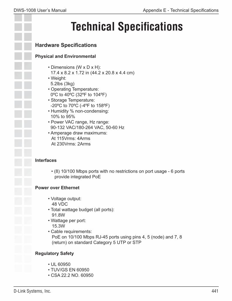
���
DWS-1008 User’s Manual
D-Link Systems, Inc.
Hardware Specifications
Physical and Environmental
• Dimensions (W x D x H): 17.4 x 8.2 x 1.72 in (44.2 x 20.8 x 4.4 cm) • Weight: 5.2lbs (3kg) • Operating Temperature: 0ºC to 40ºC (32ºF to 104ºF) • Storage Temperature: -20ºC to 70ºC (-4ºF to 158ºF) • Humidity % non-condensing: 10% to 95% • Power VAC range, Hz range: 90-132 VAC/180-264 VAC, 50-60 Hz • Amperage draw maximums:
At 115Vrms: 4ArmsAt 230Vrms: 2Arms
Interfaces
• (8) 10/100 Mbps ports with no restrictions on port usage - 6 portsprovide integrated PoE
Power over Ethernet
• Voltage output: 48 VDC • Total wattage budget (all ports): 91.8W • Wattage per port: 15.3W • Cable requirements: PoE on 10/100 Mbps RJ-45 ports using pins 4, 5 (node) and 7, 8 (return) on standard Category 5 UTP or STP
Regulatory Safety
• UL 60950 • TUV/GS EN 60950 • CSA 22.2 NO. 60950
Technical Specifications
Appendix E - Technical Specifications
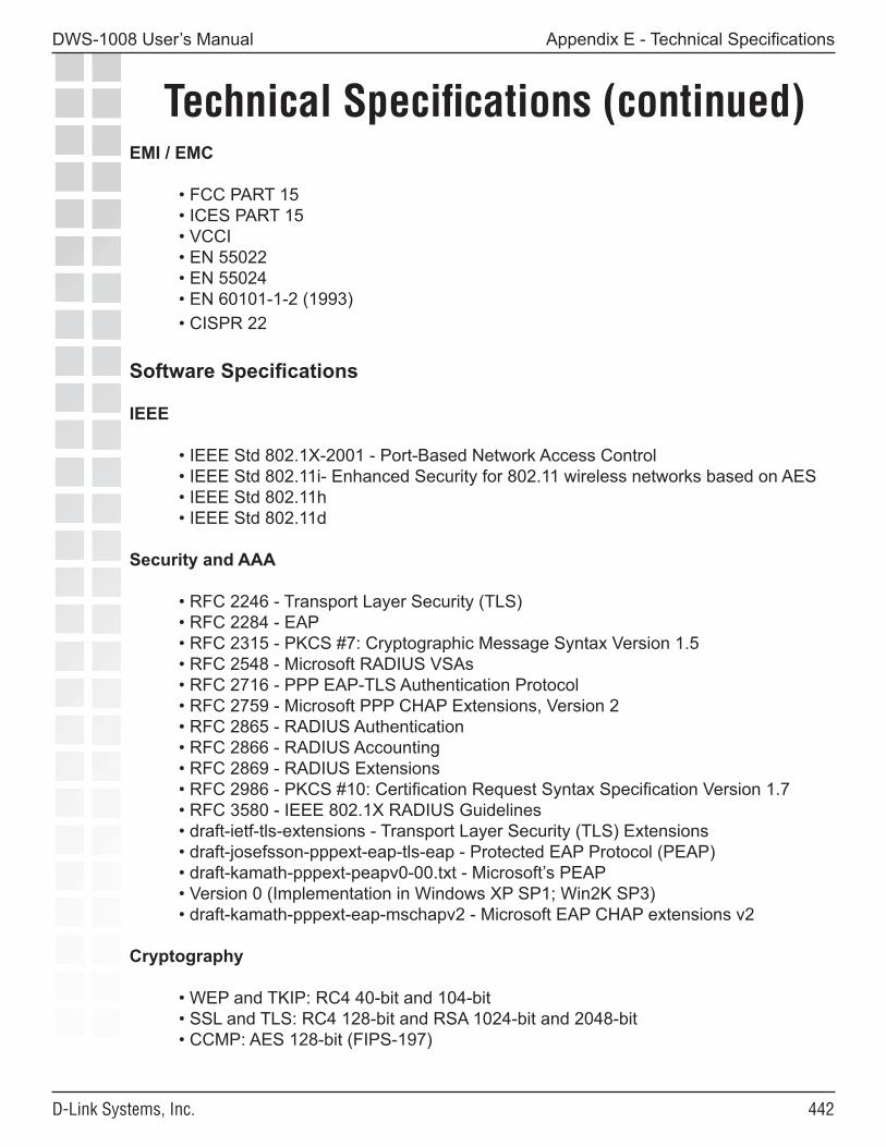
���
DWS-1008 User’s Manual
D-Link Systems, Inc.
Technical Specifications (continued)
Appendix E - Technical Specifications
EMI / EMC
• FCC PART 15 • ICES PART 15 • VCCI • EN 55022 • EN 55024 • EN 60101-1-2 (1993) • CISPR 22
Software Specifications
IEEE
• IEEE Std 802.1X-2001 - Port-Based Network Access Control • IEEE Std 802.11i- Enhanced Security for 802.11 wireless networks based on AES • IEEE Std 802.11h • IEEE Std 802.11d
Security and AAA
• RFC 2246 - Transport Layer Security (TLS) • RFC 2284 - EAP • RFC 2315 - PKCS #7: Cryptographic Message Syntax Version 1.5 • RFC 2548 - Microsoft RADIUS VSAs • RFC 2716 - PPP EAP-TLS Authentication Protocol • RFC 2759 - Microsoft PPP CHAP Extensions, Version 2 • RFC 2865 - RADIUS Authentication • RFC 2866 - RADIUS Accounting • RFC 2869 - RADIUS Extensions • RFC 2986 - PKCS #10: Certification Request Syntax Specification Version 1.7 • RFC 3580 - IEEE 802.1X RADIUS Guidelines • draft-ietf-tls-extensions - Transport Layer Security (TLS) Extensions • draft-josefsson-pppext-eap-tls-eap - Protected EAP Protocol (PEAP) • draft-kamath-pppext-peapv0-00.txt - Microsoft’s PEAP • Version 0 (Implementation in Windows XP SP1; Win2K SP3) • draft-kamath-pppext-eap-mschapv2 - Microsoft EAP CHAP extensions v2
Cryptography
• WEP and TKIP: RC4 40-bit and 104-bit • SSL and TLS: RC4 128-bit and RSA 1024-bit and 2048-bit • CCMP: AES 128-bit (FIPS-197)
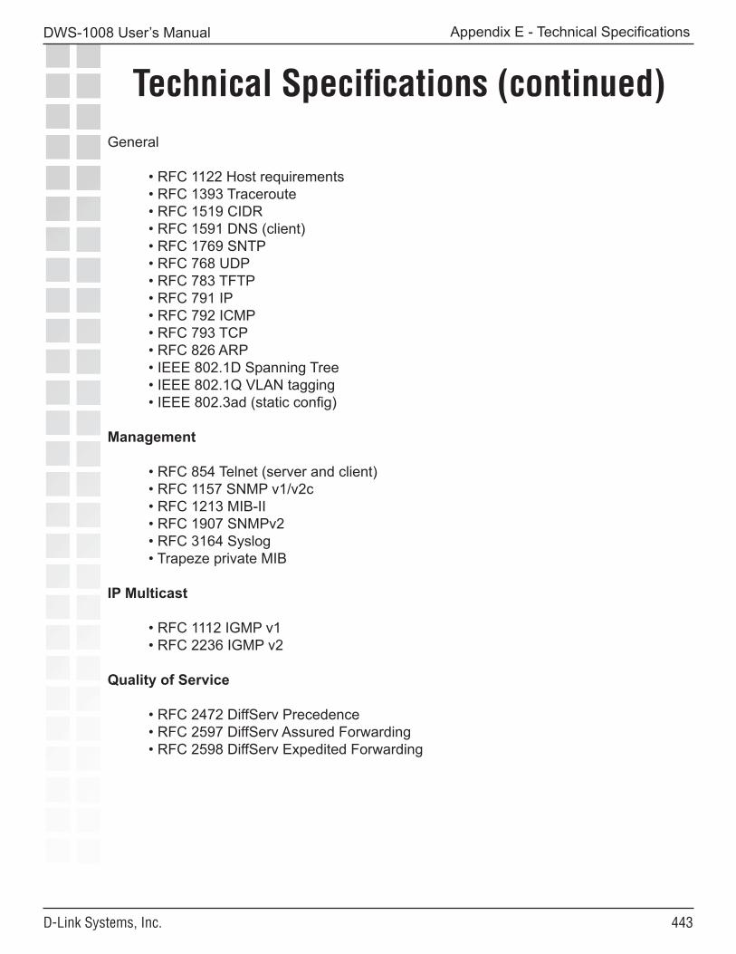
���
DWS-1008 User’s Manual
D-Link Systems, Inc.
Technical Specifications (continued)
Appendix E - Technical Specifications
General
• RFC 1122 Host requirements • RFC 1393 Traceroute • RFC 1519 CIDR • RFC 1591 DNS (client) • RFC 1769 SNTP • RFC 768 UDP • RFC 783 TFTP • RFC 791 IP • RFC 792 ICMP • RFC 793 TCP • RFC 826 ARP • IEEE 802.1D Spanning Tree • IEEE 802.1Q VLAN tagging • IEEE 802.3ad (static config)
Management
• RFC 854 Telnet (server and client) • RFC 1157 SNMP v1/v2c • RFC 1213 MIB-II • RFC 1907 SNMPv2 • RFC 3164 Syslog • Trapeze private MIB
IP Multicast
• RFC 1112 IGMP v1 • RFC 2236 IGMP v2
Quality of Service
• RFC 2472 DiffServ Precedence • RFC 2597 DiffServ Assured Forwarding • RFC 2598 DiffServ Expedited Forwarding
���
DWS-1008 User’s Manual
D-Link Systems, Inc.
Warranty
Appendix F - Warranty
Subject to the terms and conditions set forth herein, D-Link Systems, Inc. (“D-Link”) provides this Limited warranty for its product only to the person or entity that originally purchased the product from: • D-Link or its authorized reseller or distributor and • Products purchased and delivered within the fifty states of the United States, the District of Columbia, U.S. Possessions or Protectorates, U.S. Military Installations, addresses with an APO or FPO.
Limited Warranty:D-Link warrants that the hardware portion of the D-Link products described below will be free from material defects in workmanship and materials from the date of original retail purchase of the product, for the period set forth below applicable to the product type (“Warranty Period”), except as otherwise stated herein.
1-Year Limited Warranty for the Product(s) is defined as follows: • Hardware (excluding power supplies and fans) One (1) Year • Power Supplies and Fans One (1) Year • Spare parts and spare kits Ninety (90) days
D-Link’s sole obligation shall be to repair or replace the defective Hardware during the Warranty Period at no charge to the original owner or to refund at D-Link’s sole discretion. Such repair or replacement will be rendered by D-Link at an Authorized D-Link Service Office. The replacement Hardware need not be new or have an identical make, model or part. D-Link may in its sole discretion replace the defective Hardware (or any part thereof) with any reconditioned product that D-Link reasonably determines is substantially equivalent (or superior) in all material respects to the defective Hardware. Repaired or replacement Hardware will be warranted for the remainder of the original Warranty Period from the date of original retail purchase. If a material defect is incapable of correction, or if D-Link determines in its sole discretion that it is not practical to repair or replace the defective Hardware, the price paid by the original purchaser for the defective Hardware will be refunded by D-Link upon return to D-Link of the defective Hardware. All Hardware (or part thereof) that is replaced by D-Link, or for which the purchase price is refunded, shall become the property of D-Link upon replacement or refund.
Limited Software Warranty:D-Link warrants that the software portion of the product (“Software”) will substantially conform to D-Link’s then current functional specifications for the Software, as set forth in the applicable documentation, from the date of original retail purchase of the Software for a period of ninety (90) days (“Warranty Period”), provided that the Software is properly installed on approved hardware and operated as contemplated in its documentation. D-Link further warrants that, during the Warranty Period, the magnetic media on which D-Link delivers the Software will be free of physical defects. D-Link’s sole obligation shall be to replace the non-conforming Software (or defective media) with software that substantially conforms to D-Link’s functional specifications for the Software or to refund at D-Link’s sole discretion.
���
DWS-1008 User’s Manual
D-Link Systems, Inc.
Except as otherwise agreed by D-Link in writing, the replacement Software is provided only to the original licensee, and is subject to the terms and conditions of the license granted by D-Link for the Software. Software will be warranted for the remainder of the original Warranty Period from the date or original retail purchase. If a material non-conformance is incapable of correction, or if D-Link determines in its sole discretion that it is not practical to replace the non-conforming Software, the price paid by the original licensee for the non-conforming Software will be refunded by D-Link; provided that the non-conforming Software (and all copies thereof) is first returned to D-Link. The license granted respecting any Software for which a refund is given automatically terminates.
Non-Applicability of Warranty:The Limited Warranty provided hereunder for hardware and software of D-Link’s products will not be applied to and does not cover any refurbished product and any product purchased through the inventory clearance or liquidation sale or other sales in which D-Link, the sellers, or the liquidators expressly disclaim their warranty obligation pertaining to the product and in that case, the product is being sold “As-Is” without any warranty whatsoever including, without limitation, the Limited Warranty as described herein, notwithstanding anything stated herein to the contrary.
Submitting A Claim:The customer shall return the product to the original purchase point based on its return policy. In case the return policy period has expired and the product is within warranty, the customer shall submit a claim to D-Link as outlined below:
• The customer must submit with the product as part of the claim a written description of the Hardware defect or Software nonconformance in sufficient detail to allow D-Link to confirm the same.
• The original product owner must obtain a Return Material Authorization (“RMA”) number from the Authorized D-Link Service Office and, if requested, provide written proof of purchase of the product (such as a copy of the dated purchase invoice for the product) before the warranty service is provided.
• After an RMA number is issued, the defective product must be packaged securely in the original or other suitable shipping package to ensure that it will not be damaged in transit, and the RMA number must be prominently marked on the outside of the package. Do not include any manuals or accessories in the shipping package. D-Link will only replace the defective portion of the Product and will not ship back any accessories.
• The customer is responsible for all in-bound shipping charges to D-Link. No Cash on Delivery (“COD”) is allowed. Products sent COD will either be rejected by D-Link or become the property of D-Link. Products shall be fully insured by the customer. D-Link will not be held responsible for any packages that are lost in transit to D-Link. The repaired or replaced packages will be shipped to the customer via UPS Ground or any common carrier selected by D-Link, with shipping charges prepaid. Expedited shipping is available if shipping charges are prepaid by the customer and upon request.
• Return Merchandise Ship-To Address(USA): 17595 Mt. Herrmann, Fountain Valley, CA 92708(Canada): 2180 Winston Park Drive, Oakville, ON, L6H 5W1(Visit http://www.dlink.ca for detailed warranty information within Canada)
Appendix F - Warranty
���
DWS-1008 User’s Manual
D-Link Systems, Inc.
D-Link may reject or return any product that is not packaged and shipped in strict compliance with the foregoing requirements, or for which an RMA number is not visible from the outside of the package. The product owner agrees to pay D-Link’s reasonable handling and return shipping charges for any product that is not packaged and shipped in accordance with the foregoing requirements, or that is determined by D-Link not to be defective or non-conforming.
What Is Not Covered:This limited warranty provided by D-Link does not cover:Products, if in D-Link’s judgment, have been subjected to abuse, accident, alteration, modification, tampering, negligence, misuse, faulty installation, lack of reasonable care, repair or service in any way that is not contemplated in the documentation for the product, or if the model or serial number has been altered, tampered with, defaced or removed; Initial installation, installation and removal of the product for repair, and shipping costs; Operational adjustments covered in the operating manual for the product, and normal maintenance; Damage that occurs in shipment, due to act of God, failures due to power surge, and cosmetic damage; Any hardware, software, firmware or other products or services provided by anyone other than D-Link; Products that have been purchased from inventory clearance or liquidation sales or other sales in which D-Link, the sellers, or the liquidators expressly disclaim their warranty obligation pertaining to the product. Repair by anyone other than D-Link or an Authorized D-Link Service Office will void this Warranty.
Disclaimer of Other Warranties:EXCEPT FOR THE LIMITED WARRANTY SPECIFIED HEREIN, THE PRODUCT IS PROVIDED “AS-IS” WITHOUT ANY WARRANTY OF ANY KIND WHATSOEVER INCLUDING, WITHOUT LIMITATION, ANY WARRANTY OF MERCHANTABILITY, FITNESS FOR A PARTICULAR PURPOSE AND NON-INFRINGEMENT. IF ANY IMPLIED WARRANTY CANNOT BE DISCLAIMED IN ANY TERRITORY WHERE A PRODUCT IS SOLD, THE DURATION OF SUCH IMPLIED WARRANTY SHALL BE LIMITED TO NINETY (90) DAYS. EXCEPT AS EXPRESSLY COVERED UNDER THE LIMITED WARRANTY PROVIDED HEREIN, THE ENTIRE RISK AS TO THE QUALITY, SELECTION AND PERFORMANCE OF THE PRODUCT IS WITH THE PURCHASER OF THE PRODUCT.
Appendix F - Warranty

���
DWS-1008 User’s Manual
D-Link Systems, Inc.
Limitation of Liability:TO THE MAXIMUM EXTENT PERMITTED BY LAW, D-LINK IS NOT LIABLE UNDER ANY CONTRACT, NEGLIGENCE, STRICT LIABILITY OR OTHER LEGAL OR EQUITABLE THEORY FOR ANY LOSS OF USE OF THE PRODUCT, INCONVENIENCE OR DAMAGES OF ANY CHARACTER, WHETHER DIRECT, SPECIAL, INCIDENTAL OR CONSEQUENTIAL (INCLUDING, BUT NOT LIMITED TO, DAMAGES FOR LOSS OF GOODWILL, LOSS OF REVENUE OR PROFIT, WORK STOPPAGE, COMPUTER FAILURE OR MALFUNCTION, FAILURE OF OTHER EQUIPMENT OR COMPUTER PROGRAMS TO WHICH D-LINK’S PRODUCT IS CONNECTED WITH, LOSS OF INFORMATION OR DATA CONTAINED IN, STORED ON, OR INTEGRATED WITH ANY PRODUCT RETURNED TO D-LINK FOR WARRANTY SERVICE) RESULTING FROM THE USE OF THE PRODUCT, RELATING TO WARRANTY SERVICE, OR ARISING OUT OF ANY BREACH OF THIS LIMITED WARRANTY, EVEN IF D-LINK HAS BEEN ADVISED OF THE POSSIBILITY OF SUCH DAMAGES. THE SOLE REMEDY FOR A BREACH OF THE FOREGOING LIMITED WARRANTY IS REPAIR, REPLACEMENT OR REFUND OF THE DEFECTIVE OR NON-CONFORMING PRODUCT. THE MAXIMUM LIABILITY OF D-LINK UNDER THIS WARRANTY IS LIMITED TO THE PURCHASE PRICE OF THE PRODUCT COVERED BY THE WARRANTY. THE FOREGOING EXPRESS WRITTEN WARRANTIES AND REMEDIES ARE EXCLUSIVE AND ARE IN LIEU OF ANY OTHER WARRANTIES OR REMEDIES, EXPRESS, IMPLIED OR STATUTORY.
Governing Law:This Limited Warranty shall be governed by the laws of the State of California. Some states do not allow exclusion or limitation of incidental or consequential damages, or limitations on how long an implied warranty lasts, so the foregoing limitations and exclusions may not apply. This limited warranty provides specific legal rights and the product owner may also have other rights which vary from state to state.
Trademarks:D-Link is a registered trademark of D-Link Systems, Inc. Other trademarks or registered trademarks are the property of their respective manufacturers or owners.
Copyright Statement:No part of this publication or documentation accompanying this Product may be reproduced in any form or by any means or used to make any derivative such as translation, transformation, or adaptation without permission from D-Link Corporation/D-Link Systems, Inc., as stipulated by the United States Copyright Act of 1976. Contents are subject to change without prior notice. Copyright © 2002-2006 by D-Link Corporation/D-Link Systems, Inc. All rights reserved.
CE Mark Warning: This is a Class B product. In a domestic environment, this product may cause radio interference, in which case the user may be required to take adequate measures.
Appendix F - Warranty
���
DWS-1008 User’s Manual
D-Link Systems, Inc.
FCC Statement: This equipment has been tested and found to comply with the limits for a Class B digital device, pursuant to part 15 of the FCC Rules. These limits are designed to provide reasonable protection against harmful interference in a residential installation. This equipment generates, uses, and can radiate radio frequency energy and, if not installed and used in accordance with the instructions, may cause harmful interference to radio communication. However, there is no guarantee that interference will not occur in a particular installation. If this equipment does cause harmful interference to radio or television reception, which can be determined by turning the equipment off and on, the user is encouraged to try to correct the interference by one or more of the following measures: • Reorient or relocate the receiving antenna. • Increase the separation between the equipment and receiver. • Connect the equipment into an outlet on a circuit different from that to which the receiver is connected. • Consult the dealer or an experienced radio/TV technician for help.
For detailed warranty outside the United States, please contact corresponding local D-Link office.
FCC Caution:The manufacturer is not responsible for any radio or TV interference caused by unauthorized modifications to this equipment; such modifications could void the user’s authority to operate the equipment. (1) The devices are restricted to indoor operations within the 5.15 to 5.25GHz range. (2) For this device to operate in the 5.15 to 5.25GHz range, the devices must use integral antennas.
This device complies with Part 15 of the FCC Rules. Operation is subject to the following two conditions: (1) This device may not cause harmful interference, and (2) this device must accept any interference received, including interference that may cause undesired operation.
IMPORTANT NOTE:FCC Radiation Exposure Statement: This equipment complies with FCC radiation exposure limits set forth for an uncontrolled environment. The antenna(s) used for this equipment must be installed to provide a separation distance of at least eight inches (20 cm) from all persons. This equipment must not be operated in conjunction with any other antenna.
Appendix F - Warranty
���
DWS-1008 User’s Manual
D-Link Systems, Inc.
Registration
Appendix G - Registration
Revised: April 26, 2006 Version 1.1
Product registration is entirely voluntary and failure to complete or return this form will not diminish your warranty rights.