Embed Size (px)
Citation preview
D-Link ™ DGS-3224TGR Managed 24-Port Gigabit Ethernet Switch
User’s Guide

Information in this document is subject to change without notice.
© 2004 D-Link Computer Corporation. All rights reserved.
Reproduction in any manner whatsoever without the written permission of D-Link Computer Corporation is strictly forbidden.
Trademarks used in this text: D-Link and the D-Link logo are trademarks of D-Link Computer Corporation; Microsoft and Windows are registered trademarks of Microsoft Corporation.
Other trademarks and trade names may be used in this document to refer to either the entities claiming the marks and names or their products. D-Link Computer Corporation disclaims any proprietary interest in trademarks and trade names other than its own.
FCC Warning This equipment has been tested and found to comply with the limits for a Class A digital device, pursuant to Part 15 of the FCC Rules. These limits are designed to provide reasonable protection against harmful interference when the equipment is operated in a commercial environment. This equipment generates, uses, and can radiate radio frequency energy and, if not installed and used in accordance with this user’s guide, may cause harmful interference to radio communications. Operation of this equipment in a residential area is likely to cause harmful interference in which case the user will be required to correct the interference at his own expense.
CE Mark Warning This is a Class A product. In a domestic environment, this product may cause radio interference in which case the user may be required to take adequate measures.
Warnung!
Dies ist ein Produkt der Klasse A. Im Wohnbereich kann dieses Produkt Funkstoerungen verursachen. In diesem Fall kann vom Benutzer verlangt werden, angemessene Massnahmen zu ergreifen.
Precaución!
Este es un producto de Clase A. En un entorno doméstico, puede causar interferencias de radio, en cuyo case, puede requerirse al usuario para que adopte las medidas adecuadas.
Attention!
Ceci est un produit de classe A. Dans un environnement domestique, ce produit pourrait causer des interférences radio, auquel cas l`utilisateur devrait prendre les mesures adéquates.
Attenzione!
Il presente prodotto appartiene alla classe A. Se utilizzato in ambiente domestico il prodotto può causare interferenze radio, nel cui caso è possibile che l`utente debba assumere provvedimenti adeguati.
VCCI Warning
September 2004 P/N 6GS3224TGR03
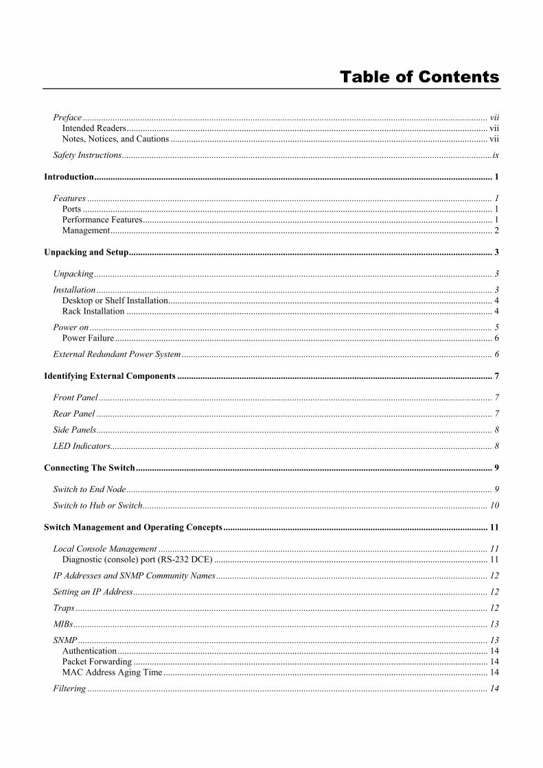
Table of Contents
Preface ................................................................................................................................................................................ vii Intended Readers............................................................................................................................................................. vii Notes, Notices, and Cautions .......................................................................................................................................... vii
Safety Instructions.................................................................................................................................................................ix
Introduction............................................................................................................................................................................. 1
Features ................................................................................................................................................................................ 1 Ports .................................................................................................................................................................................. 1 Performance Features........................................................................................................................................................ 1 Management...................................................................................................................................................................... 2
Unpacking and Setup.............................................................................................................................................................. 3
Unpacking............................................................................................................................................................................. 3 Installation ............................................................................................................................................................................ 3
Desktop or Shelf Installation............................................................................................................................................. 4 Rack Installation ............................................................................................................................................................... 4
Power on ............................................................................................................................................................................... 5 Power Failure .................................................................................................................................................................... 6
External Redundant Power System ....................................................................................................................................... 6
Identifying External Components ......................................................................................................................................... 7
Front Panel ........................................................................................................................................................................... 7 Rear Panel ............................................................................................................................................................................ 7 Side Panels............................................................................................................................................................................ 8 LED Indicators...................................................................................................................................................................... 8
Connecting The Switch........................................................................................................................................................... 9
Switch to End Node............................................................................................................................................................... 9 Switch to Hub or Switch...................................................................................................................................................... 10
Switch Management and Operating Concepts ................................................................................................................... 11
Local Console Management ............................................................................................................................................... 11 Diagnostic (console) port (RS-232 DCE) ....................................................................................................................... 11
IP Addresses and SNMP Community Names ...................................................................................................................... 12 Setting an IP Address.......................................................................................................................................................... 12 Traps ................................................................................................................................................................................... 12 MIBs.................................................................................................................................................................................... 13 SNMP .................................................................................................................................................................................. 13
Authentication................................................................................................................................................................. 14 Packet Forwarding .......................................................................................................................................................... 14 MAC Address Aging Time ............................................................................................................................................. 14
Filtering .............................................................................................................................................................................. 14
Spanning Tree ..................................................................................................................................................................... 15 802.1w Rapid Spanning Tree.......................................................................................................................................... 15
VLANs ................................................................................................................................................................................. 16 IEEE 802.1Q VLANs ..................................................................................................................................................... 16 802.1Q VLAN Packet Forwarding ................................................................................................................................. 17 802.1Q VLAN Tags........................................................................................................................................................ 18 Port VLAN ID................................................................................................................................................................. 19 Tagging and Untagging................................................................................................................................................... 19 Ingress Filtering .............................................................................................................................................................. 19
802.1x Port-Based and MAC-Based Access Control.......................................................................................................... 20 Authentication Server ..................................................................................................................................................... 21 Authenticator................................................................................................................................................................... 21 Client............................................................................................................................................................................... 22 Authentication Process.................................................................................................................................................... 23 Port-Based Network Access Control .............................................................................................................................. 23 MAC-Based Network Access Control ............................................................................................................................ 25
DHCP.................................................................................................................................................................................. 25
Web-Based Network Management...................................................................................................................................... 27
Introduction ........................................................................................................................................................................ 27 Getting Started .................................................................................................................................................................... 27 Basic Setup.......................................................................................................................................................................... 31
Switch Information ......................................................................................................................................................... 31 Basic Switch Setup.......................................................................................................................................................... 33 Serial Port Settings.......................................................................................................................................................... 34
Port Configurations ............................................................................................................................................................ 35 Port Description Settings ................................................................................................................................................ 37 Traffic Segmentation Table............................................................................................................................................. 38
User Accounts ..................................................................................................................................................................... 39 SNMP Network Management.............................................................................................................................................. 41
SNMP V3........................................................................................................................................................................ 41 SNMP View Table .......................................................................................................................................................... 41 SNMP Community Table................................................................................................................................................ 42 SNMP Host Table ........................................................................................................................................................... 43 SNMP Group Table ........................................................................................................................................................ 44 Engine ID........................................................................................................................................................................ 46 SNMP User Table ........................................................................................................................................................... 46
Management Station IP Addresses ..................................................................................................................................... 48 Switch Utilities .................................................................................................................................................................... 48
TFTP Services................................................................................................................................................................. 48 Network Monitoring............................................................................................................................................................ 52
Statistics .......................................................................................................................................................................... 52 Address Tables................................................................................................................................................................ 55 Status............................................................................................................................................................................... 57
Factory Reset ...................................................................................................................................................................... 60 Save Changes ...................................................................................................................................................................... 60
Restart System................................................................................................................................................................. 61 Logout ............................................................................................................................................................................. 61
Advanced Setup..................................................................................................................................................................... 61
Switch Advanced Settings.................................................................................................................................................... 62
Spanning Tree ..................................................................................................................................................................... 62 STP Switch Settings........................................................................................................................................................ 63 STP Port Settings ............................................................................................................................................................ 64
Forwarding ......................................................................................................................................................................... 65 MAC Address Aging Time ............................................................................................................................................. 65 Unicast MAC Address Settings ...................................................................................................................................... 66 Multicast MAC Address Settings.................................................................................................................................... 67 Broadcast/Multicast Storm Control................................................................................................................................. 68
Configure QOS.................................................................................................................................................................... 69 QOS Output Scheduling ................................................................................................................................................. 70 802.1p Default Priority ................................................................................................................................................... 71 802.1p User Priority........................................................................................................................................................ 72 Bandwidth Control Table................................................................................................................................................ 72
Access Profile Mask Setting................................................................................................................................................ 73 Port Security ....................................................................................................................................................................... 83 Port Mirroring Configurations ........................................................................................................................................... 86 VLAN Configurations.......................................................................................................................................................... 87
Asymmetric VLAN State ................................................................................................................................................ 87 Switch GVRP.................................................................................................................................................................. 87 802.1Q VLANs............................................................................................................................................................... 88 802.1Q Port Settings ....................................................................................................................................................... 90
Link Aggregation ................................................................................................................................................................ 91 Link Aggregation Algorithm .......................................................................................................................................... 91 Link Aggregation Group................................................................................................................................................. 91 LACP Port Settings......................................................................................................................................................... 93
802.1X ................................................................................................................................................................................. 95 802.1X State.................................................................................................................................................................... 95 802.1X Auth Mode Settings............................................................................................................................................ 96 802.1X Port Settings ....................................................................................................................................................... 96 802.1X Port Auth State ................................................................................................................................................. 100 802.1X Initialize / Reauthenticate Ports........................................................................................................................ 101
RADIUS Server Settings ................................................................................................................................................... 102 802.1X Local User Settings............................................................................................................................................... 103 802.1X Auth Diagnostics .................................................................................................................................................. 104 802.1X Auth Statistics ....................................................................................................................................................... 105 802.1X Auth Session Statistics .......................................................................................................................................... 106 802.1X Auth Client............................................................................................................................................................ 107
802.1X Accounting Client ............................................................................................................................................ 107 TACACS ............................................................................................................................................................................ 107
TACACS State Configuration ...................................................................................................................................... 107 TACACS Server Settings.............................................................................................................................................. 108 TACACS Group............................................................................................................................................................ 109 TACACS Group Settings.............................................................................................................................................. 109 TACACS Method List .................................................................................................................................................. 110 Authentication............................................................................................................................................................... 111 Enable Admin ............................................................................................................................................................... 111
System Log ........................................................................................................................................................................ 112 System Log State .......................................................................................................................................................... 112 System Log Host........................................................................................................................................................... 112
Multicast Configuration.................................................................................................................................................... 114 IGMP Snooping Global ................................................................................................................................................ 114
IGMP Snooping Configurations ................................................................................................................................... 115 Static Router Port Settings ............................................................................................................................................ 116
SSH Management.............................................................................................................................................................. 116 SSH Configurations ...................................................................................................................................................... 117 SSH Account Configuration ......................................................................................................................................... 118
SSL Management .............................................................................................................................................................. 119 Download Certificate .................................................................................................................................................... 119 Cipher Suite Configuration ........................................................................................................................................... 120 SSL V3 Configuration .................................................................................................................................................. 121 TLS V1 Configuration .................................................................................................................................................. 122
Single IP Management........................................................................................................................................................ 123
SIM Settings ...................................................................................................................................................................... 123 SIM Using the Web Interface ............................................................................................................................................ 124 Topology ........................................................................................................................................................................... 126
Tool Tips....................................................................................................................................................................... 128 Right-Click.................................................................................................................................................................... 129 Commander Switch Icon............................................................................................................................................... 130 Menu Bar ...................................................................................................................................................................... 133 Device ........................................................................................................................................................................... 134 View.............................................................................................................................................................................. 134
Firmware Upgrade ........................................................................................................................................................... 135 Configuration Backup/Restore.......................................................................................................................................... 135
Technical Specifications ..................................................................................................................................................... 136
Cable Lengths...................................................................................................................................................................... 138
Glossary ............................................................................................................................................................................... 139
Warranty and Registration Information .......................................................................................................................... 142
DGS-3224TGR Gigabit Ethernet Switch User’s Guide
vii
Preface
The DGS-3224TGR User’s Guide is divided into chapters that describe the system installation and operating instructions with examples.
Chapter 1, “Introduction” – Describes the Switch and its features.
Chapter 2, “Unpacking and Setup” – Helps you get started with the basic installation of the Switch.
Chapter 3, “Identifying External Components” – Describes the front panel, rear panel, and LED indicators of the Switch.
Chapter 4, “Connecting the Switch” – Tells how you can connect the DGS-3224TGR to your Gigabit Ethernet network.
Chapter 5, “Switch Management and Operating Concepts” – Talks about management via the RS-232 DCE console port and other aspects about how to manage the Switch.
Chapter 6, “Web-Based Network Management” – Tells how to manage the Switch through an Internet browser.
Chapter 7, “D-Link’s Single IP Management” – An introduction to the new D-Link switch management feature used to manage multiple switches through a single Switch.
Appendix A, “Technical Specifications” – Lists the technical specifications of the DGS-3224TGR.
Appendix B, “Cable Lengths” – Contains chart for fiber-optic and copper cable maximum distances.
Glossary – Lists definitions for terms and acronyms used in this document.
Intended Readers
The DGS-3224TGR User’s Guide contains information for setup and management and of the DGS-3224TGR switch. This guide is intended for network managers familiar with network management concepts and terminology.
Notes, Notices, and Cautions
NOTE: A NOTE indicates important information that helps you make better use of your device.
NOTICE: A NOTICE indicates either potential damage to hardware or loss of data and tells you how to avoid the problem.

DGS-3224TGR Gigabit Ethernet Switch User’s Guide
viii
CAUTION: A CAUTION indicates a potential for property damage, personal injury, or death.

DGS-3224TGR Gigabit Ethernet Switch User’s Guide
ix
Safety Instructions
Use the following safety guidelines to ensure your own personal safety and to help protect your system from potential damage. Throughout this safety section, the caution icon ( ) is used to indicate cautions and precautions that you need to review and follow.
Safety Cautions
To reduce the risk of bodily injury, electrical shock, fire, and damage to the equipment, observe the following precautions.
Observe and follow service markings. Do not service any product except as explained in your system documentation. Opening or removing covers that are marked with the triangular symbol with a lightning bolt
may expose you to electrical shock. Only a trained service technician should service components inside these compartments.
If any of the following conditions occur, unplug the product from the electrical outlet and replace the part or contact your trained service provider:
– The power cable, extension cable, or plug is damaged.
– An object has fallen into the product.
– The product has been exposed to water.
– The product has been dropped or damaged.
– The product does not operate correctly when you follow the operating instructions.
• Keep your system away from radiators and heat sources. Also, do not block cooling vents.
• Do not spill food or liquids on your system components, and never operate the product in a wet environment. If the system gets wet, see the appropriate section in your troubleshooting guide or contact your trained service provider.
• Do not push any objects into the openings of your system. Doing so can cause fire or electric shock by shorting out interior components.
• Use the product only with approved equipment.
• Allow the product to cool before removing covers or touching internal components.
• Operate the product only from the type of external power source indicated on the electrical ratings label. If you are not sure of the type of power source required, consult your service provider or local power company.
• To help avoid damaging your system, be sure the voltage selection switch (if provided) on the power supply is set to match the power available at your location:
– 115 volts (V)/60 hertz (Hz) in most of North and South America and some Far Eastern countries such as South Korea and Taiwan
– 100 V/50 Hz in eastern Japan and 100 V/60 Hz in western Japan
– 230 V/50 Hz in most of Europe, the Middle East, and the Far East
• Also be sure that attached devices are electrically rated to operate with the power available in your location.
• Use only approved power cable(s). If you have not been provided with a power cable for your system or for any AC-powered option intended for your system, purchase a power cable that is approved for use in your country. The power cable must be rated for the product and for the voltage and current marked on the product's electrical ratings label. The voltage and current rating of the cable should be greater than the ratings marked on the product.

DGS-3224TGR Gigabit Ethernet Switch User’s Guide
x
Safety Instructions (continued) • To help prevent electric shock, plug the system and peripheral power cables into properly grounded electrical
outlets. These cables are equipped with three-prong plugs to help ensure proper grounding. Do not use adapter plugs or remove the grounding prong from a cable. If you must use an extension cable, use a 3-wire cable with properly grounded plugs.
• Observe extension cable and power strip ratings. Make sure that the total ampere rating of all products plugged into the extension cable or power strip does not exceed 80 percent of the ampere ratings limit for the extension cable or power strip.
• To help protect your system from sudden, transient increases and decreases in electrical power, use a surge suppressor, line conditioner, or uninterruptible power supply (UPS).
• Position system cables and power cables carefully; route cables so that they cannot be stepped on or tripped over. Be sure that nothing rests on any cables.
• Do not modify power cables or plugs. Consult a licensed electrician or your power company for site modifications. Always follow your local/national wiring rules.
• When connecting or disconnecting power to hot-pluggable power supplies, if offered with your system, observe the following guidelines:
– Install the power supply before connecting the power cable to the power supply.
– Unplug the power cable before removing the power supply.
– If the system has multiple sources of power, disconnect power from the system by
unplugging all power cables from the power supplies.
• Move products with care; ensure that all casters and/or stabilizers are firmly connected to the system. Avoid sudden stops and uneven surfaces.
General Precautions for Rack-Mountable Products
Observe the following precautions for rack stability and safety. Also refer to the rack installation documentation accompanying the system and the rack for specific caution statements and procedures.
Systems are considered to be components in a rack. Thus, "component" refers to any system as well as to various peripherals or supporting hardware.
CAUTION: Installing systems in a rack without the front and side stabilizers installed could cause the rack to tip over, potentially resulting in bodily injury under certain circumstances. Therefore, always install the stabilizers before installing components in the rack.
After installing system/components in a rack, never pull more than one component out of the rack on its slide assemblies at one time. The weight of more than one extended component could cause the rack to tip over and may result in serious injury.
• Before working on the rack, make sure that the stabilizers are secured to the rack, extended to the floor, and that the full weight of the rack rests on the floor. Install front and side stabilizers on a single rack or front stabilizers for joined multiple racks before working on the rack.
DGS-3224TGR Gigabit Ethernet Switch User’s Guide
xi
Safety Instructions (continued) Always load the rack from the bottom up, and load the heaviest item in the rack first.
Make sure that the rack is level and stable before extending a component from the rack.
Use caution when pressing the component rail release latches and sliding a component into or out of a rack; the slide rails can pinch your fingers.
After a component is inserted into the rack, carefully extend the rail into a locking position, and then slide the component into the rack.
Do not overload the AC supply branch circuit that provides power to the rack. The total rack load should not exceed 80 percent of the branch circuit rating.
Ensure that proper airflow is provided to components in the rack.
Do not step on or stand on any component when servicing other components in a rack.
NOTE: A qualified electrician must perform all connections to DC power and to safety grounds. All electrical wiring must comply with applicable local or national codes and practices.
CAUTION: Never defeat the ground conductor or operate the equipment in the absence of a suitably installed ground conductor. Contact the appropriate electrical inspection authority or an electrician if you are uncertain that suitable grounding is available.
CAUTION: The system chassis must be positively grounded to the rack cabinet frame. Do not attempt to connect power to the system until grounding cables are connected. Completed power and safety ground wiring must be inspected by a qualified electrical inspector. An energy hazard will exist if the safety ground cable is omitted or disconnected.

DGS-3224TGR Gigabit Ethernet Switch User’s Guide
xii
Protecting Against Electrostatic Discharge Static electricity can harm delicate components inside your system. To prevent static damage, discharge static electricity from your body before you touch any of the electronic components, such as the microprocessor. You can do so by periodically touching an unpainted metal surface on the chassis.
You can also take the following steps to prevent damage from electrostatic discharge (ESD):
1. When unpacking a static-sensitive component from its shipping carton, do not remove the component from the antistatic packing material until you are ready to install the component in your system. Just before unwrapping the antistatic packaging, be sure to discharge static electricity from your body.
2. When transporting a sensitive component, first place it in an antistatic container or packaging.
3. Handle all sensitive components in a static-safe area. If possible, use antistatic floor pads and workbench pads and an antistatic grounding strap.
Battery Handling Reminder
CAUTION: Danger of explosion if battery is incorrectly replaced. Replace only with the same or equivalent type recommended by the manufacturer. Discard used batteries according to the manufacturer's instructions.
DGS-3224TGR Gigabit Ethernet Switch User’s Guide
1
1 Introduction This section describes the features of the DGS-3224TGR.
Features
The DGS-3224TGR was designed for departmental and enterprise connections. As an all-gigabit-port switch, it is ideal for backbone and server connection. Powerful and versatile, the switch eliminates network bottlenecks while giving users the capability to fine-tune performance
Switch features include:
Ports
• Twenty-four high performance 1000BASE-T ports for making 10/100/1000 connections to a backbone, end stations, and servers.
• Four mini-GBIC (SFP) combo ports to connect fiber optic media to another switch, server or network backbone.
• RS-232 DCE Diagnostic port (console port) for setting up and managing the Switch via a connection to a console terminal or PC using a terminal emulation program.
Performance Features • Store-and-forward switching scheme. • Switching fabric: 48Gbps • Max. Forwarding Rate: 35.7 million packets per second • High-speed data forwarding rate of 1,488,095 pps per port at 100% of wire-speed for 1000 Mbps speed. • Supports 16K MAC address. • Supports eight priority queues per port. • Supports 2Mbytes buffer memory per switch. • Jumbo Frame support (up to 9216 bytes). • Multi-layer (Layer 2 to Layer 4) ACL and CoS support. • Administrator-definable port security. • 802.1D Spanning Tree support. Can be disabled on the entire switch or on a per-port basis. • 802.1w Rapid Reconfiguration of Spanning Tree. • 802.1Q Tagged VLAN support, including GVRP (GARP VLAN Registration Protocol). • Support for up to 255 VLANs. • IGMP snooping support per switch and fast-leave. • Link aggregation support for up to 32 trunk groups and 8 trunk members per group. Support LACP and Static mode. • Both port-based and MAC-based 802.1x port access control. • Per-port bandwidth control.
DGS-3224TGR Gigabit Ethernet Switch User’s Guide
2
Management
• RS-232 console port for out-of-band network management via a console terminal.
• Spanning Tree Algorithm Protocol for creation of alternative backup paths and prevention of network loops.
• SNMP V.1, V2c1, and V3 network management, 4 groups of RMON.
• Flash memory for software upgrades. This can be done in-band via TFTP or out-of-band via the console.
• Built-in SNMP management:
Bridge MIB (RFC 1493)
MIB-II (RFC 1213)
802.1P/Q MIB (RFC 2674)
Interface MIB (RFC 2233)
Ethernet-like MIB (RFC 1643)
Mini-RMON MIB (RFC 1757) – 4 groups. The RMON specification defines the counters for the receive functions only. However, the DGS-3224TGR provides counters for both receive and transmit functions.
• Supports Web-based management.
• TFTP support.
• BOOTP support.
• DHCP Client support.
• Password enabled.
• Telnet remote control console.
• Broadcast storm control.
• Multicast storm control.
• Command Line Interface support.
• Port security support.
• TACACS and TACACS+ protocol support.
• SYSLOG support.
• Destination Lookup Fail control.
• SSL support.
• Single IP Management v1.0 support.
DGS-3224TGR Gigabit Ethernet Switch User’s Guide
3
2 Unpacking and Setup This chapter provides unpacking and setup information for the switch.
Unpacking
Open the shipping carton of the switch and carefully unpack its contents. The carton should contain the following items:
• A DGS-3224TGR 24-Port Gigabit Layer 2 Ethernet switch
• A mounting kit: 2 mounting brackets and screws
• Four rubber feet with adhesive backing
• One or two AC power cords
• A printed QIG
• A printed User’s Guide
• D-View 5.1 demo CD-ROM
• This User’s Guide with Registration Card on CD-ROM
If any item is found missing or damaged, please contact your local D-Link reseller for replacement.
Installation
Use the following guidelines when choosing a place to install the switch:
• The surface must support at least 4 kg.
• The power outlet should be within 1.82 meters (6 feet) of the device.
• Visually inspect the power cord and see that it is secured to the AC power connector.
• Make sure that there is proper heat dissipation from and adequate ventilation around the switch. Do not place heavy objects on the switch.
DGS-3224TGR Gigabit Ethernet Switch User’s Guide
4
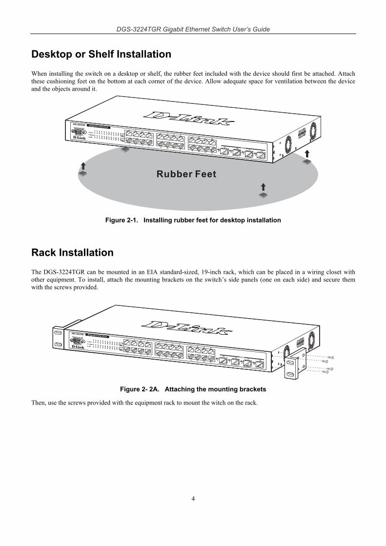
Desktop or Shelf Installation
When installing the switch on a desktop or shelf, the rubber feet included with the device should first be attached. Attach these cushioning feet on the bottom at each corner of the device. Allow adequate space for ventilation between the device and the objects around it.
Figure 2-1. Installing rubber feet for desktop installation
Rack Installation
The DGS-3224TGR can be mounted in an EIA standard-sized, 19-inch rack, which can be placed in a wiring closet with other equipment. To install, attach the mounting brackets on the switch’s side panels (one on each side) and secure them with the screws provided.
Figure 2- 2A. Attaching the mounting brackets
Then, use the screws provided with the equipment rack to mount the witch on the rack.
DGS-3224TGR Gigabit Ethernet Switch User’s Guide
5
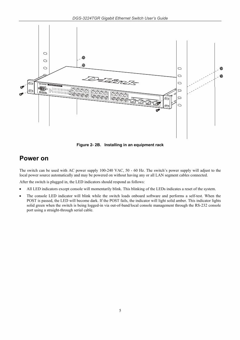
Figure 2- 2B. Installing in an equipment rack
Power on
The switch can be used with AC power supply 100-240 VAC, 50 - 60 Hz. The switch’s power supply will adjust to the local power source automatically and may be powered on without having any or all LAN segment cables connected.
After the switch is plugged in, the LED indicators should respond as follows:
• All LED indicators except console will momentarily blink. This blinking of the LEDs indicates a reset of the system.
• The console LED indicator will blink while the switch loads onboard software and performs a self-test. When the POST is passed, the LED will become dark. If the POST fails, the indicator will light solid amber. This indicator lights solid green when the switch is being logged-in via out-of-band/local console management through the RS-232 console port using a straight-through serial cable.
DGS-3224TGR Gigabit Ethernet Switch User’s Guide
6
Power Failure
As a precaution in the event of a power failure, unplug the switch. When power is resumed, plug the switch back in.
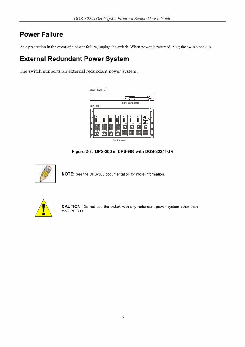
External Redundant Power System
The switch supports an external redundant power system.
Figure 2-3. DPS-300 in DPS-900 with DGS-3224TGR
NOTE: See the DPS-300 documentation for more information.
CAUTION: Do not use the switch with any redundant power system other than the DPS-300.
DGS-3224TGR Gigabit Ethernet Switch User’s Guide
7
3 Identifying External Components This chapter describes the front panel, rear panel, side panels, and LED indicators of the DGS-3224TGR.
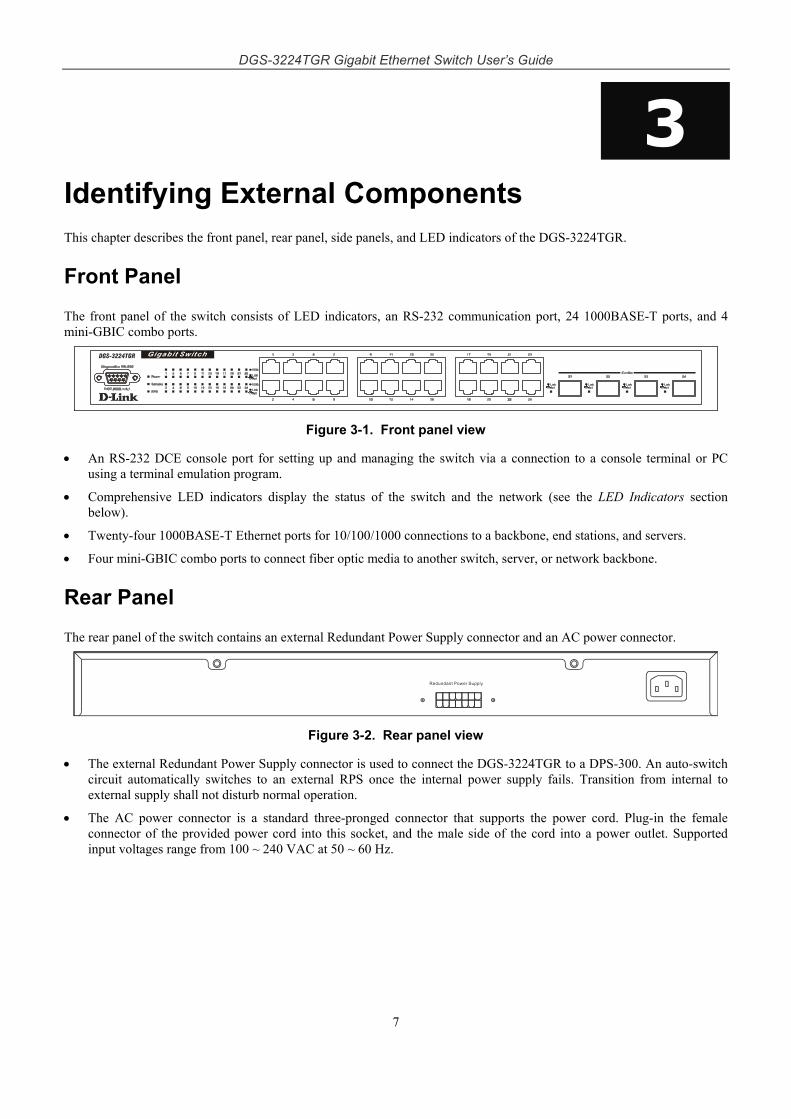
Front Panel
The front panel of the switch consists of LED indicators, an RS-232 communication port, 24 1000BASE-T ports, and 4 mini-GBIC combo ports.
Figure 3-1. Front panel view
• An RS-232 DCE console port for setting up and managing the switch via a connection to a console terminal or PC using a terminal emulation program.
• Comprehensive LED indicators display the status of the switch and the network (see the LED Indicators section below).
• Twenty-four 1000BASE-T Ethernet ports for 10/100/1000 connections to a backbone, end stations, and servers.
• Four mini-GBIC combo ports to connect fiber optic media to another switch, server, or network backbone.
Rear Panel
The rear panel of the switch contains an external Redundant Power Supply connector and an AC power connector.
Figure 3-2. Rear panel view
• The external Redundant Power Supply connector is used to connect the DGS-3224TGR to a DPS-300. An auto-switch circuit automatically switches to an external RPS once the internal power supply fails. Transition from internal to external supply shall not disturb normal operation.
• The AC power connector is a standard three-pronged connector that supports the power cord. Plug-in the female connector of the provided power cord into this socket, and the male side of the cord into a power outlet. Supported input voltages range from 100 ~ 240 VAC at 50 ~ 60 Hz.
DGS-3224TGR Gigabit Ethernet Switch User’s Guide
8
Side Panels
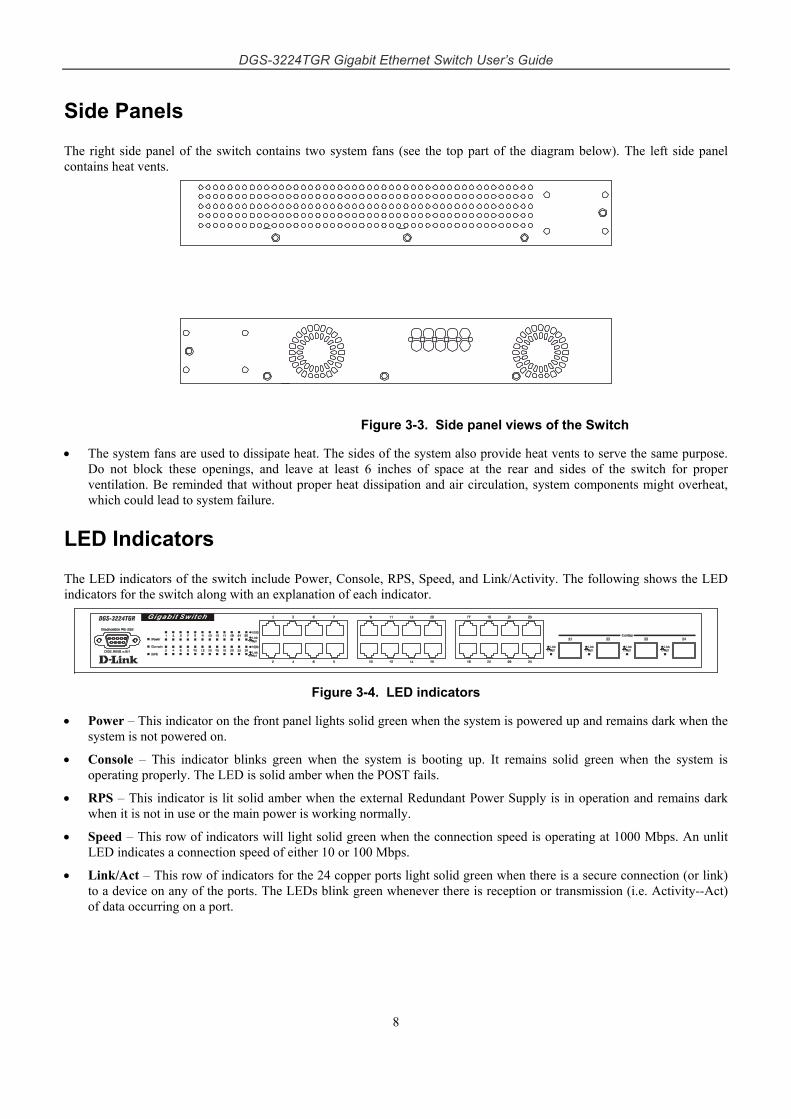
The right side panel of the switch contains two system fans (see the top part of the diagram below). The left side panel contains heat vents.
Figure 3-3. Side panel views of the Switch
• The system fans are used to dissipate heat. The sides of the system also provide heat vents to serve the same purpose. Do not block these openings, and leave at least 6 inches of space at the rear and sides of the switch for proper ventilation. Be reminded that without proper heat dissipation and air circulation, system components might overheat, which could lead to system failure.
LED Indicators
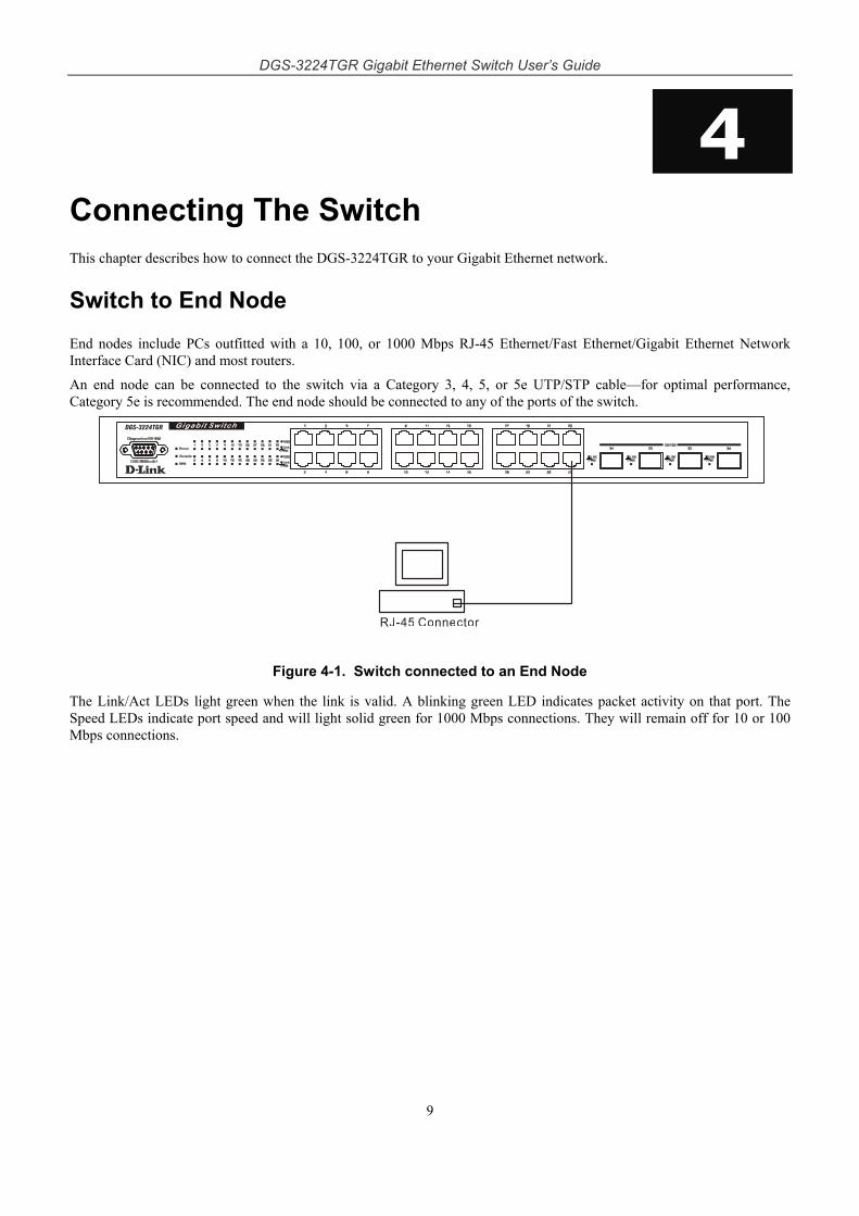
The LED indicators of the switch include Power, Console, RPS, Speed, and Link/Activity. The following shows the LED indicators for the switch along with an explanation of each indicator.
Figure 3-4. LED indicators
• Power – This indicator on the front panel lights solid green when the system is powered up and remains dark when the system is not powered on.
• Console – This indicator blinks green when the system is booting up. It remains solid green when the system is operating properly. The LED is solid amber when the POST fails.
• RPS – This indicator is lit solid amber when the external Redundant Power Supply is in operation and remains dark when it is not in use or the main power is working normally.
• Speed – This row of indicators will light solid green when the connection speed is operating at 1000 Mbps. An unlit LED indicates a connection speed of either 10 or 100 Mbps.
• Link/Act – This row of indicators for the 24 copper ports light solid green when there is a secure connection (or link) to a device on any of the ports. The LEDs blink green whenever there is reception or transmission (i.e. Activity--Act) of data occurring on a port.
DGS-3224TGR Gigabit Ethernet Switch User’s Guide
9
4 Connecting The Switch This chapter describes how to connect the DGS-3224TGR to your Gigabit Ethernet network.
Switch to End Node
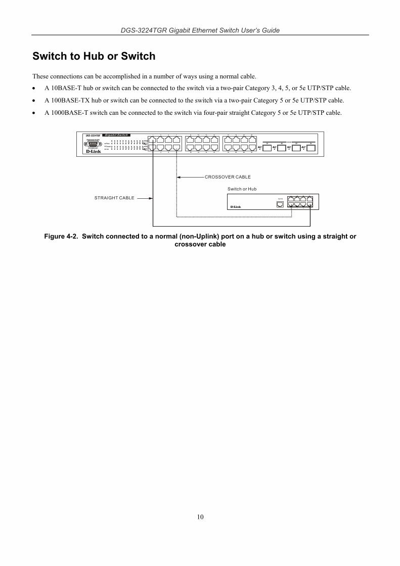
End nodes include PCs outfitted with a 10, 100, or 1000 Mbps RJ-45 Ethernet/Fast Ethernet/Gigabit Ethernet Network Interface Card (NIC) and most routers.
An end node can be connected to the switch via a Category 3, 4, 5, or 5e UTP/STP cable—for optimal performance, Category 5e is recommended. The end node should be connected to any of the ports of the switch.
Figure 4-1. Switch connected to an End Node
The Link/Act LEDs light green when the link is valid. A blinking green LED indicates packet activity on that port. The Speed LEDs indicate port speed and will light solid green for 1000 Mbps connections. They will remain off for 10 or 100 Mbps connections.
DGS-3224TGR Gigabit Ethernet Switch User’s Guide
10
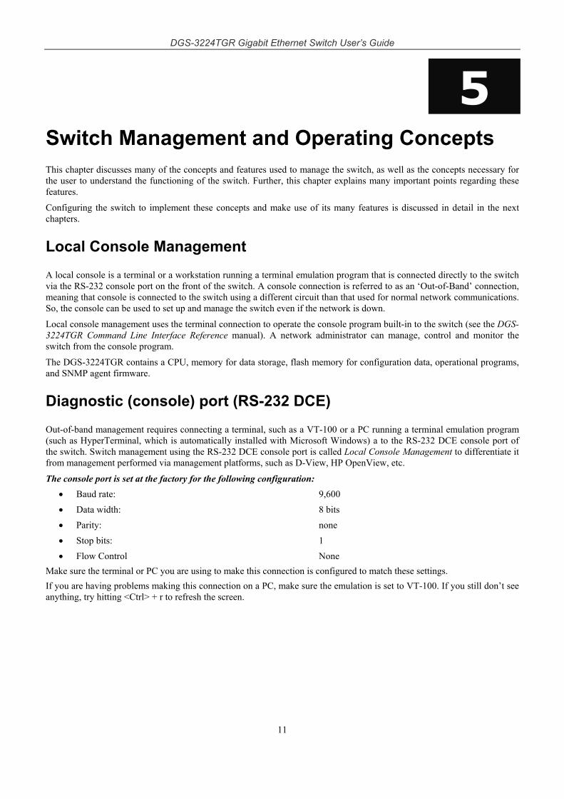
Switch to Hub or Switch
These connections can be accomplished in a number of ways using a normal cable.
• A 10BASE-T hub or switch can be connected to the switch via a two-pair Category 3, 4, 5, or 5e UTP/STP cable.
• A 100BASE-TX hub or switch can be connected to the switch via a two-pair Category 5 or 5e UTP/STP cable.
• A 1000BASE-T switch can be connected to the switch via four-pair straight Category 5 or 5e UTP/STP cable.
Figure 4-2. Switch connected to a normal (non-Uplink) port on a hub or switch using a straight or crossover cable
DGS-3224TGR Gigabit Ethernet Switch User’s Guide
11
5 Switch Management and Operating Concepts This chapter discusses many of the concepts and features used to manage the switch, as well as the concepts necessary for the user to understand the functioning of the switch. Further, this chapter explains many important points regarding these features.
Configuring the switch to implement these concepts and make use of its many features is discussed in detail in the next chapters.
Local Console Management
A local console is a terminal or a workstation running a terminal emulation program that is connected directly to the switch via the RS-232 console port on the front of the switch. A console connection is referred to as an ‘Out-of-Band’ connection, meaning that console is connected to the switch using a different circuit than that used for normal network communications. So, the console can be used to set up and manage the switch even if the network is down.
Local console management uses the terminal connection to operate the console program built-in to the switch (see the DGS-3224TGR Command Line Interface Reference manual). A network administrator can manage, control and monitor the switch from the console program.
The DGS-3224TGR contains a CPU, memory for data storage, flash memory for configuration data, operational programs, and SNMP agent firmware.
Diagnostic (console) port (RS-232 DCE)
Out-of-band management requires connecting a terminal, such as a VT-100 or a PC running a terminal emulation program (such as HyperTerminal, which is automatically installed with Microsoft Windows) a to the RS-232 DCE console port of the switch. Switch management using the RS-232 DCE console port is called Local Console Management to differentiate it from management performed via management platforms, such as D-View, HP OpenView, etc.
The console port is set at the factory for the following configuration: • Baud rate: 9,600 • Data width: 8 bits • Parity: none • Stop bits: 1 • Flow Control None
Make sure the terminal or PC you are using to make this connection is configured to match these settings. If you are having problems making this connection on a PC, make sure the emulation is set to VT-100. If you still don’t see anything, try hitting <Ctrl> + r to refresh the screen.
DGS-3224TGR Gigabit Ethernet Switch User’s Guide
12
IP Addresses and SNMP Community Names
Each switch must be assigned its own IP Address, which is used for communication with an SNMP network manager or other TCP/IP application (for example BOOTP, TFTP). The switch’s default IP address is 10.90.90.90. You can change the default switch IP Address to meet the specification of your networking address scheme.
The switch is also assigned a unique MAC address by the factory. This MAC address cannot be changed, and can be found when using the command “show switch.”
In addition, you can also set an IP address for a gateway router. This becomes necessary when the network management station is located on a different IP network from the switch, making it necessary for management packets to go through a router to reach the network manager, and vice-versa.
For security, you can set in the switch a list of IP Addresses of the network managers that allow you to manage the switch. You can also change the default SNMP Community Strings in the switch and set the access rights of these Community Strings. In addition, a VLAN may be designated as a Management VLAN.
Setting an IP Address
The IP address for the switch must be set before it can be managed with the Web-based manager. The switch IP address may be automatically set using BOOTP or DHCP protocols, in which case the actual address assigned to the switch must be known.
The IP address may alternatively be set using the Command Line Interface (CLI) over the console serial port as follows:
1. Starting at the command line prompt local>, enter the commands config ipif System ipaddress xxx.xxx.xxx.xxx/yyy.yyy.yyy.yyy. Where the x’s represent the IP address to be assigned to the IP interface named System and the y’s represent the corresponding subnet mask.
2. Alternatively, you can enter the commands config ipif System ipaddress xxx.xxx.xxx.xxx/z. Where the x’s represent the IP address to be assigned to the IP interface named System and the z represents the corresponding number of subnets in CIDR notation.
Using this method, the switch can be assigned an IP address and subnet mask that can then be used to connect a management station to the switch’s Web-based management agent.
Traps
Traps are messages that alert you of events that occur on the switch. The events can be as serious as a reboot (someone accidentally turned OFF the switch), or less serious like a port status change. The switch generates traps and sends them to the network manager (trap recipient).
Trap recipients are special users of the network who are given certain rights and access in overseeing the maintenance of the network. Trap recipients will receive traps sent from the switch; they must immediately take certain actions to avoid future failure or breakdown of the network.
You can also specify which network managers may receive traps from the switch by entering a list of the IP addresses of authorized network managers. Up to four trap recipient IP addresses, and four corresponding SNMP community strings can be entered.
SNMP community strings function like passwords in that the community string entered for a given IP address must be used in the management station software, or a trap will be sent.
The following are trap types the switch can send to a trap recipient:
• Cold Start –This trap signifies that the switch has been powered up and initialized such that software settings are reconfigured and hardware systems are rebooted. A cold start is different from a factory reset in that configuration settings saved to non-volatile RAM used to reconfigure the switch.
• Authentication Failure – This trap signifies that someone has tried to logon to the switch using an invalid SNMP community string. The switch automatically stores the source IP address of the unauthorized user.
DGS-3224TGR Gigabit Ethernet Switch User’s Guide
13
• New Root – This trap indicates that the switch has become the new root of the Spanning Tree, the trap is sent by the switch soon after its election as the new root. This implies that upon expiration of the Topology Change Timer the new root trap is sent out immediately after the switch’s election as the new root.
• Topology Change (STP) – A Topology Change trap is sent by the switch when any of its configured ports transitions from the Learning state to the Forwarding state, or from the Forwarding state to the Blocking state. The trap is not sent if a new root trap is sent for the same transition.
• Connected and Working – This trap is sent when the Redundant Power Supply is connected and working.
• Disconnect or Malfunction – This trap is sent whenever the Redundant Power Supply malfunctions.
• MAC Notification – This trap indicates that the switch had learned a new MAC address.
MIBs
Management and counter information are stored in the switch in the Management Information Base (MIB. The switch uses the standard MIB-II Management Information Base module. Consequently, values for MIB objects can be retrieved from any SNMP-based network management software. In addition to the standard MIB-II, the switch also supports its own proprietary enterprise MIB as an extended Management Information Base. These MIBs may also be retrieved by specifying the MIB’s Object-Identity (OID) at the network manager. MIB values can be either read-only or read-write.
Read-only MIBs variables can be either constants that are programmed into the switch, or variables that change while the switch is in operation. Examples of read-only constants are the number of port and type of ports. Examples of read-only variables are the statistics counters such as the number of errors that have occurred, or how many kilobytes of data have been received and forwarded through a port.
Read-write MIBs are variables usually related to user-customized configurations. Examples of these are the switch’s IP Address, Spanning Tree Algorithm parameters, and port status.
If you use a third-party vendors’ SNMP software to manage the switch, a diskette listing the switch’s propriety enterprise MIBs can be obtained by request. If your software provides functions to browse or modify MIBs, you can also get the MIB values and change them (if the MIBs’ attributes permit the write operation). This process however can be quite involved, since you must know the MIB OIDs and retrieve them one by one.
SNMP
The Simple Network Management Protocol (SNMP) is an OSI layer 7 (the application layer) protocol for remotely monitoring and configuring network devices. SNMP enables network management stations to read and modify the settings of gateways, routers, switches, and other network devices. SNMP can be used to perform many of the same functions as a directly connected console, or can be used within an integrated network management software package such as HP OpenView or DView.
SNMP performs the following functions:
• Sending and receiving SNMP packets through the IP protocol.
• Collecting information about the status and current configuration of network devices.
• Modifying the configuration of network devices.
The DGS-3224TGR has a software program called an ‘agent’ that processes SNMP requests, but the user program that makes the requests and collects the responses runs on a management station (a designated computer on the network). The SNMP agent and the user program both use the UDP/IP protocol to exchange packets.
DGS-3224TGR Gigabit Ethernet Switch User’s Guide
14
Authentication
The authentication protocol ensures that both the router SNMP agent and the remote user SNMP application program discard packets from unauthorized users. Authentication is accomplished using ‘community strings’, which function like passwords. The remote user SNMP application and the router SNMP must use the same community string.
Packet Forwarding
The switch enters the relationship between destination MAC or IP addresses and the Ethernet port or gateway router the destination resides on into its forwarding table. This information is then used to forward packets. This reduces the traffic congestion on the network, because packets, instead of being transmitted to all ports, are transmitted to the destination port only. Example: if Port 1 receives a packet destined for a station on Port 2, the switch transmits that packet through Port 2 only, and transmits nothing through the other ports. This process is referred to as ‘learning’ the network topology.
MAC Address Aging Time
The Aging Time affects the learning process of the Switch. Dynamic forwarding table entries, which are made up of the source and destination MAC addresses and their associated port numbers, are deleted from the table if they are not accessed within the aging time.
The aging time can be from 10 to 1,000,000 seconds with a default value of 300 seconds. A very long aging time can result in dynamic forwarding table entries that are out-of-date or no longer exist. This may cause incorrect packet forwarding decisions by the Switch.
If the Aging Time is too short however, many entries may be aged out too soon. This will result in a high percentage of received packets whose source addresses cannot be found in the forwarding table, in which case the switch will broadcast the packet to all ports, negating many of the benefits of having a switch.
Static forwarding entries are not affected by the aging time.
Filtering
The switch uses a filtering database to segment the network and control communication between segments. It can also filter packets off the network for intrusion control. Static filtering entries can be made by MAC Address filtering.
Each port on the switch is a unique collision domain and the switch filters (discards) packets whose destination lies on the same port as where it originated. This keeps local packets from disrupting communications on other parts of the network.
For intrusion control, whenever a switch encounters a packet originating from or destined to a MAC address entered into the filter table, the switch will discard the packet.
Some filtering is done automatically by the switch:
• Dynamic filtering – automatic learning and aging of MAC addresses and their location on the network. Filtering occurs to keep local traffic confined to its segment.
• Filtering done by the Spanning Tree Protocol that can filter packets based on topology, making sure that signal loops don’t occur.
• Filtering done for VLAN integrity. Packets from a member of a VLAN (VLAN 2, for example) destined for a device on another VLAN (VLAN 3) will be filtered.
DGS-3224TGR Gigabit Ethernet Switch User’s Guide
15
Spanning Tree
802.1w Rapid Spanning Tree
The DGS-3224TGR implements two versions of the Spanning Tree Protocol, the Rapid Spanning Tree Protocol (RSTP) as defined by the IEE 802.1w specification and a version compatible with the IEEE 802.1d STP. RSTP can operate with legacy equipment implementing IEEE 802.1d, however the advantages of using RSTP will be lost.
The IEEE 802.1w Rapid Spanning Tree Protocol (RSTP) evolved from the 802.1d STP standard. RSTP was developed in order to overcome some limitations of STP that impede the function of some recent switching innovations, in particular, certain Layer 3 function that are increasingly handled by Ethernet switches. The basic function and much of the terminology is the same as STP. Most of the settings configured for STP are also used for RSTP. This section introduces some new Spanning Tree concepts and illustrates the main differences between the two protocols.
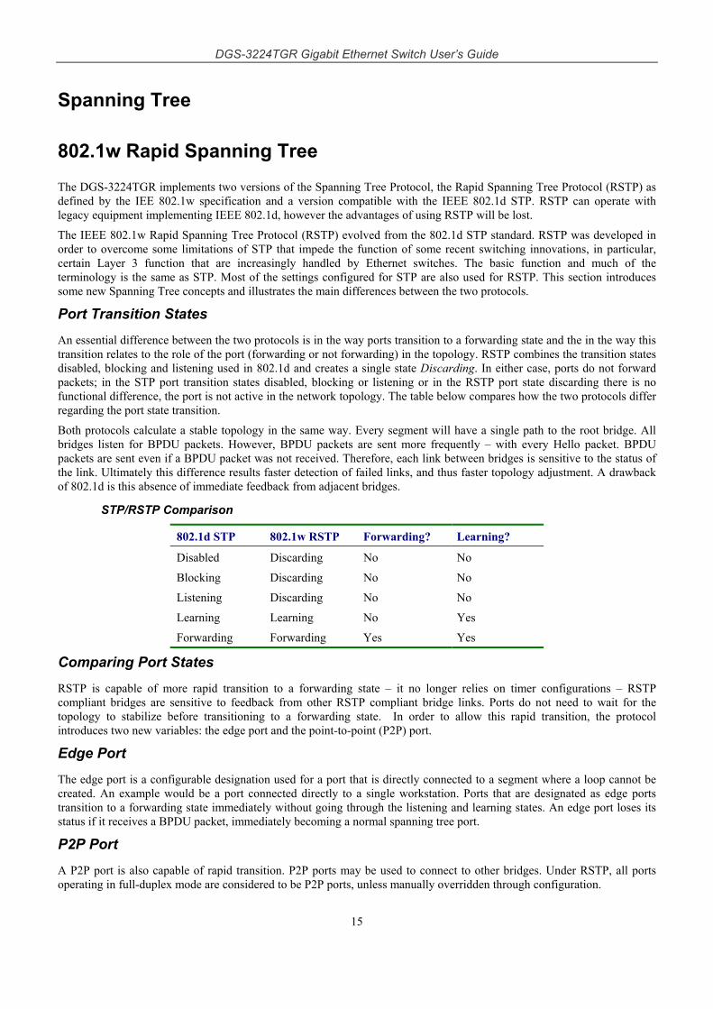
Port Transition States An essential difference between the two protocols is in the way ports transition to a forwarding state and the in the way this transition relates to the role of the port (forwarding or not forwarding) in the topology. RSTP combines the transition states disabled, blocking and listening used in 802.1d and creates a single state Discarding. In either case, ports do not forward packets; in the STP port transition states disabled, blocking or listening or in the RSTP port state discarding there is no functional difference, the port is not active in the network topology. The table below compares how the two protocols differ regarding the port state transition.
Both protocols calculate a stable topology in the same way. Every segment will have a single path to the root bridge. All bridges listen for BPDU packets. However, BPDU packets are sent more frequently – with every Hello packet. BPDU packets are sent even if a BPDU packet was not received. Therefore, each link between bridges is sensitive to the status of the link. Ultimately this difference results faster detection of failed links, and thus faster topology adjustment. A drawback of 802.1d is this absence of immediate feedback from adjacent bridges.
STP/RSTP Comparison
802.1d STP 802.1w RSTP Forwarding? Learning?
Disabled Discarding No No
Blocking Discarding No No
Listening Discarding No No
Learning Learning No Yes
Forwarding Forwarding Yes Yes
Comparing Port States RSTP is capable of more rapid transition to a forwarding state – it no longer relies on timer configurations – RSTP compliant bridges are sensitive to feedback from other RSTP compliant bridge links. Ports do not need to wait for the topology to stabilize before transitioning to a forwarding state. In order to allow this rapid transition, the protocol introduces two new variables: the edge port and the point-to-point (P2P) port.
Edge Port The edge port is a configurable designation used for a port that is directly connected to a segment where a loop cannot be created. An example would be a port connected directly to a single workstation. Ports that are designated as edge ports transition to a forwarding state immediately without going through the listening and learning states. An edge port loses its status if it receives a BPDU packet, immediately becoming a normal spanning tree port.
P2P Port A P2P port is also capable of rapid transition. P2P ports may be used to connect to other bridges. Under RSTP, all ports operating in full-duplex mode are considered to be P2P ports, unless manually overridden through configuration.
DGS-3224TGR Gigabit Ethernet Switch User’s Guide
16
802.1d/802.1w Compatibility RSTP can interoperate with legacy equipment and is capable of automatically adjusting BPDU packets to 802.1d format when necessary. However, any segment using 802.1 STP will not benefit from the rapid transition and rapid topology change detection of RSTP. The protocol also provides for a variable used for migration in the event that legacy equipment on a segment is updated to use RSTP.
The Spanning Tree Protocol (STP) operates on two levels: on the switch level, the settings are globally implemented. On the port level, the settings are implemented on a user-defined Group of ports basis.
VLANs
A Virtual Local Area Network (VLAN) is a network topology configured according to a logical scheme rather than the physical layout. VLANs can be used to combine any collection of LAN segments into an autonomous user group that appears as a single LAN. VLANs also logically segment the network into different broadcast domains so that packets are forwarded only between ports within the VLAN. Typically, a VLAN corresponds to a particular subnet, although not necessarily.
VLANs can enhance performance by conserving bandwidth, and improve security by limiting traffic to specific domains.
A VLAN is a collection of end nodes grouped by logic instead of physical location. End nodes that frequently communicate with each other are assigned to the same VLAN, regardless of where they are physically on the network. Logically, a VLAN can be equated to a broadcast domain, because broadcast packets are forwarded to only members of the VLAN on which the broadcast was initiated.
Note: VLANs on the DGS-3224TGR
No matter what basis is used to uniquely identify end nodes and assign these nodes VLAN membership, packets cannot cross VLANs without a network device performing a routing function between the VLANs.
The DGS-3224TGR supports only IEEE 802.1Q VLANs. The port untagging function can be used to remove the 802.1Q tag from packet headers to maintain compatibility with devices that are tag-unaware.
The switch’s default is to assign all ports to a single 802.1Q VLAN named “default.”
The default VLAN has a VID = 1
IEEE 802.1Q VLANs
Some relevant terms:
• Tagging – The act of putting 802.1Q VLAN information into the header of a packet.
• Untagging – The act of stripping 802.1Q VLAN information out of the packet header.
• Ingress port – A port on a switch where packets are flowing into the switch and VLAN decisions must be made.
• Egress port – A port on a switch where packets are flowing out of the switch, either to another switch or to an end station, and tagging decisions must be made.
IEEE 802.1Q (tagged) VLANs are implemented on the DGS-3224TGR 802.1Q VLANs require tagging, which enables them to span the entire network (assuming all switches on the network are IEEE 802.1Q-compliant).
VLANs allow a network to be segmented in order to reduce the size of broadcast domains. All packets entering a VLAN will only be forwarded to the stations (over IEEE 802.1Q enabled switches) that are members of that VLAN, and this includes broadcast, multicast and unicast packets from unknown sources.
VLANs can also provide a level of security to your network. IEEE 802.1Q VLANs will only deliver packets between stations that are members of the VLAN.
DGS-3224TGR Gigabit Ethernet Switch User’s Guide
17
Any port can be configured as either tagging or untagging. The untagging feature of IEEE 802.1Q VLANs allows VLANs to work with legacy switches that don’t recognize VLAN tags in packet headers. The tagging feature allows VLANs to span multiple 802.1Q-compliant switches through a single physical connection and allows Spanning Tree to be enabled on all ports and work normally.
The IEEE 802.1Q standard restricts the forwarding of untagged packets to the VLAN the receiving port is a member of.
The main characteristics of IEEE 802.1Q are as follows:
• Assigns packets to VLANs by filtering.
• Assumes the presence of a single global spanning tree.
• Uses an explicit tagging scheme with one-level tagging
802.1Q VLAN Packet Forwarding
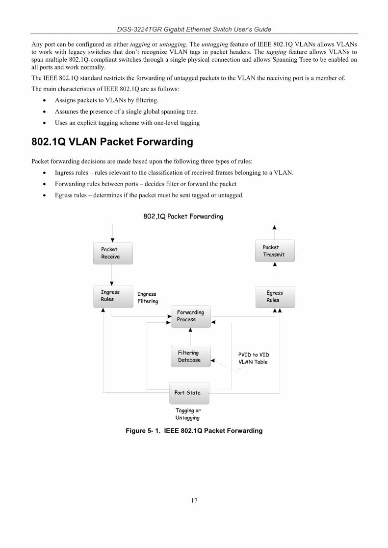
Packet forwarding decisions are made based upon the following three types of rules:
• Ingress rules – rules relevant to the classification of received frames belonging to a VLAN.
• Forwarding rules between ports – decides filter or forward the packet
• Egress rules – determines if the packet must be sent tagged or untagged.
Figure 5- 1. IEEE 802.1Q Packet Forwarding
DGS-3224TGR Gigabit Ethernet Switch User’s Guide
18
802.1Q VLAN Tags
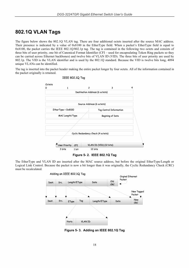
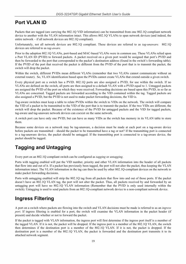
The figure below shows the 802.1Q VLAN tag. There are four additional octets inserted after the source MAC address. Their presence is indicated by a value of 0x8100 in the EtherType field. When a packet’s EtherType field is equal to 0x8100, the packet carries the IEEE 802.1Q/802.1p tag. The tag is contained in the following two octets and consists of three bits of user priority, one bit of Canonical Format Identifier (CFI – used for encapsulating Token Ring packets so they can be carried across Ethernet backbones) and twelve bits of VLAN ID (VID). The three bits of user priority are used by 802.1p. The VID is the VLAN identifier and is used by the 802.1Q standard. Because the VID is twelve bits long, 4094 unique VLANs can be identified.
The tag is inserted into the packet header making the entire packet longer by four octets. All of the information contained in the packet originally is retained.
Figure 5- 2. IEEE 802.1Q Tag
The EtherType and VLAN ID are inserted after the MAC source address, but before the original EtherType/Length or Logical Link Control. Because the packet is now a bit longer than it was originally, the Cyclic Redundancy Check (CRC) must be recalculated.
Figure 5- 3. Adding an IEEE 802.1Q Tag
DGS-3224TGR Gigabit Ethernet Switch User’s Guide
19
Port VLAN ID
Packets that are tagged (are carrying the 802.1Q VID information) can be transmitted from one 802.1Q compliant network device to another with the VLAN information intact. This allows 802.1Q VLANs to span network devices (and indeed, the entire network – if all network devices are 802.1Q compliant).
Unfortunately, not all network devices are 802.1Q compliant. These devices are referred to as tag-unaware. 802.1Q devices are referred to as tag-aware.
Prior to the adoption 802.1Q VLANs, port-based and MAC-based VLANs were in common use. These VLANs relied upon a Port VLAN ID (PVID) to forward packets. A packet received on a given port would be assigned that port’s PVID and then be forwarded to the port that corresponded to the packet’s destination address (found in the switch’s forwarding table). If the PVID of the port that received the packet is different from the PVID of the port that is to transmit the packet, the switch will drop the packet.
Within the switch, different PVIDs mean different VLANs (remember that two VLANs cannot communicate without an external router). So, VLAN identification based upon the PVIDs cannot create VLANs that extend outside a given switch.
Every physical port on a switch has a PVID. 802.1Q ports are also assigned a PVID, for use within the switch. If no VLANs are defined on the switch, all ports are then assigned to a default VLAN with a PVID equal to 1. Untagged packets are assigned the PVID of the port on which they were received. Forwarding decisions are based upon this PVID, in so far as VLANs are concerned. Tagged packets are forwarded according to the VID contained within the tag. Tagged packets are also assigned a PVID, but the PVID is not used to make packet forwarding decisions, the VID is.
Tag-aware switches must keep a table to relate PVIDs within the switch to VIDs on the network. The switch will compare the VID of a packet to be transmitted to the VID of the port that is to transmit the packet. If the two VIDs are different, the switch will drop the packet. Because of the existence of the PVID for untagged packets and the VID for tagged packets, tag-aware and tag-unaware network devices can coexist on the same network.
A switch port can have only one PVID, but can have as many VIDs as the switch has memory in its VLAN table to store them.
Because some devices on a network may be tag-unaware, a decision must be made at each port on a tag-aware device before packets are transmitted – should the packet to be transmitted have a tag or not? If the transmitting port is connected to a tag-unaware device, the packet should be untagged. If the transmitting port is connected to a tag-aware device, the packet should be tagged.
Tagging and Untagging
Every port on an 802.1Q compliant switch can be configured as tagging or untagging.
Ports with tagging enabled will put the VID number, priority and other VLAN information into the header of all packets that flow into and out of it. If a packet has previously been tagged, the port will not alter the packet, thus keeping the VLAN information intact. The VLAN information in the tag can then be used by other 802.1Q-compliant devices on the network to make packet forwarding decisions.
Ports with untagging enabled will strip the 802.1Q tag from all packets that flow into and out of those ports. If the packet doesn’t have an 802.1Q VLAN tag, the port will not alter the packet. Thus, all packets received by and forwarded by an untagging port will have no 802.1Q VLAN information (Remember that the PVID is only used internally within the switch). Untagging is used to send packets from an 802.1Q-compliant network device to a non-compliant network device.
Ingress Filtering
A port on a switch where packets are flowing into the switch and VLAN decisions must be made is referred to as an ingress port. If ingress filtering is enabled for a port, the switch will examine the VLAN information in the packet header (if present) and decide whether or not to forward the packet.
If the packet is tagged with VLAN information, the ingress port will first determine if the ingress port itself is a member of the tagged VLAN. If it is not, the packet will be dropped. If the ingress port is a member of the 802.1Q VLAN, the switch then determines if the destination port is a member of the 802.1Q VLAN. If it is not, the packet is dropped. If the destination port is a member of the 802.1Q VLAN, the packet is forwarded and the destination port transmits it to its attached network segment.
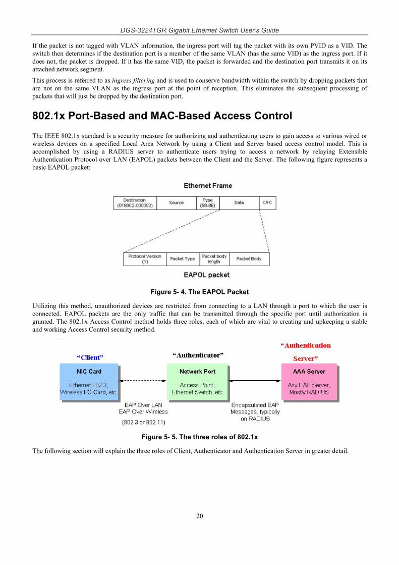
DGS-3224TGR Gigabit Ethernet Switch User’s Guide
20
If the packet is not tagged with VLAN information, the ingress port will tag the packet with its own PVID as a VID. The switch then determines if the destination port is a member of the same VLAN (has the same VID) as the ingress port. If it does not, the packet is dropped. If it has the same VID, the packet is forwarded and the destination port transmits it on its attached network segment.
This process is referred to as ingress filtering and is used to conserve bandwidth within the switch by dropping packets that are not on the same VLAN as the ingress port at the point of reception. This eliminates the subsequent processing of packets that will just be dropped by the destination port.
802.1x Port-Based and MAC-Based Access Control
The IEEE 802.1x standard is a security measure for authorizing and authenticating users to gain access to various wired or wireless devices on a specified Local Area Network by using a Client and Server based access control model. This is accomplished by using a RADIUS server to authenticate users trying to access a network by relaying Extensible Authentication Protocol over LAN (EAPOL) packets between the Client and the Server. The following figure represents a basic EAPOL packet:
Figure 5- 4. The EAPOL Packet
Utilizing this method, unauthorized devices are restricted from connecting to a LAN through a port to which the user is connected. EAPOL packets are the only traffic that can be transmitted through the specific port until authorization is granted. The 802.1x Access Control method holds three roles, each of which are vital to creating and upkeeping a stable and working Access Control security method.
Figure 5- 5. The three roles of 802.1x
The following section will explain the three roles of Client, Authenticator and Authentication Server in greater detail.
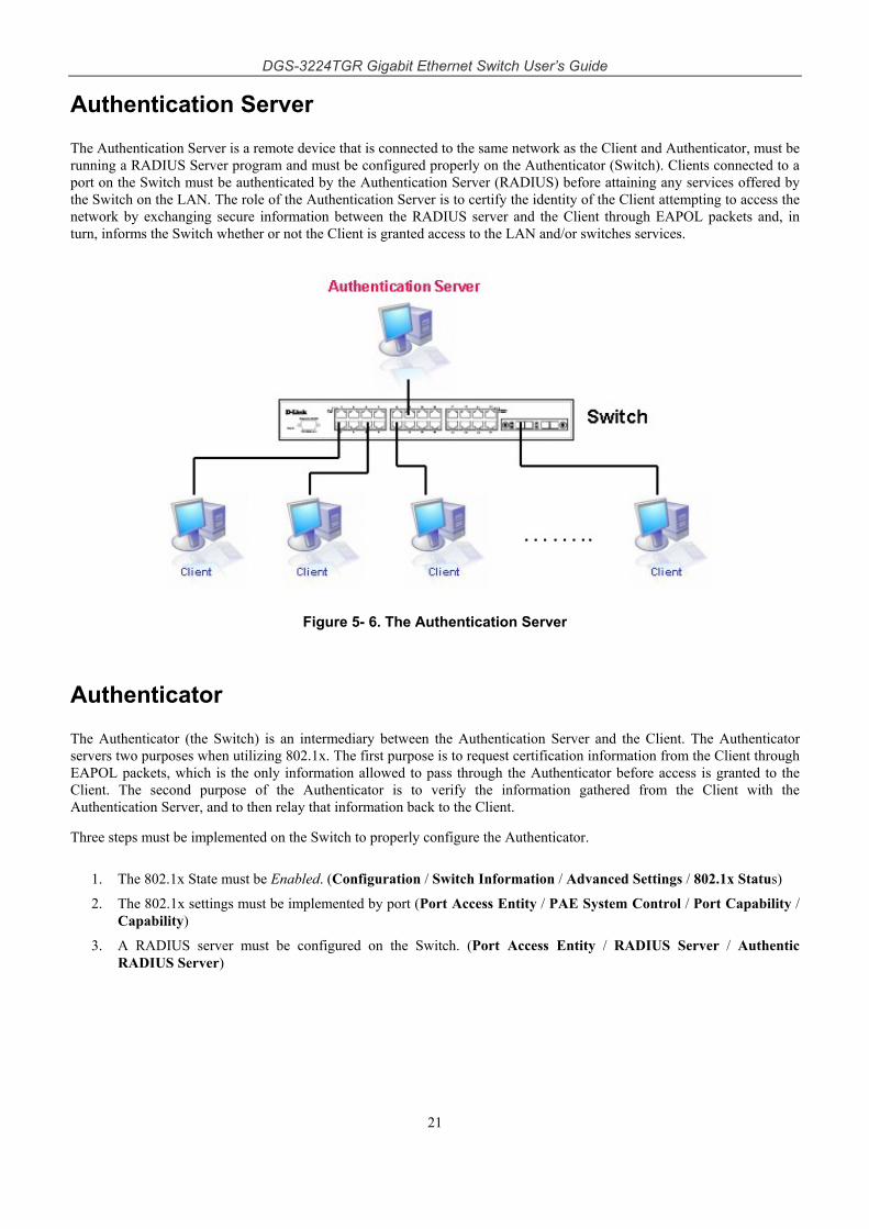
DGS-3224TGR Gigabit Ethernet Switch User’s Guide
21
Authentication Server
The Authentication Server is a remote device that is connected to the same network as the Client and Authenticator, must be running a RADIUS Server program and must be configured properly on the Authenticator (Switch). Clients connected to a port on the Switch must be authenticated by the Authentication Server (RADIUS) before attaining any services offered by the Switch on the LAN. The role of the Authentication Server is to certify the identity of the Client attempting to access the network by exchanging secure information between the RADIUS server and the Client through EAPOL packets and, in turn, informs the Switch whether or not the Client is granted access to the LAN and/or switches services.
Figure 5- 6. The Authentication Server
Authenticator
The Authenticator (the Switch) is an intermediary between the Authentication Server and the Client. The Authenticator servers two purposes when utilizing 802.1x. The first purpose is to request certification information from the Client through EAPOL packets, which is the only information allowed to pass through the Authenticator before access is granted to the Client. The second purpose of the Authenticator is to verify the information gathered from the Client with the Authentication Server, and to then relay that information back to the Client.
Three steps must be implemented on the Switch to properly configure the Authenticator.
1. The 802.1x State must be Enabled. (Configuration / Switch Information / Advanced Settings / 802.1x Status)
2. The 802.1x settings must be implemented by port (Port Access Entity / PAE System Control / Port Capability / Capability)
3. A RADIUS server must be configured on the Switch. (Port Access Entity / RADIUS Server / Authentic RADIUS Server)
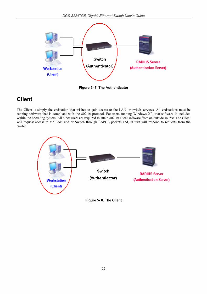
DGS-3224TGR Gigabit Ethernet Switch User’s Guide
22
Figure 5- 7. The Authenticator
Client
The Client is simply the endstation that wishes to gain access to the LAN or switch services. All endstations must be running software that is compliant with the 802.1x protocol. For users running Windows XP, that software is included within the operating system. All other users are required to attain 802.1x client software from an outside source. The Client will request access to the LAN and or Switch through EAPOL packets and, in turn will respond to requests from the Switch.
Figure 5- 8. The Client
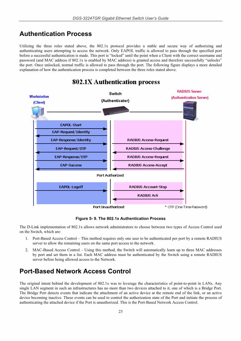
DGS-3224TGR Gigabit Ethernet Switch User’s Guide
23
Authentication Process
Utilizing the three roles stated above, the 802.1x protocol provides a stable and secure way of authorizing and authenticating users attempting to access the network. Only EAPOL traffic is allowed to pass through the specified port before a successful authentication is made. This port is “locked” until the point when a Client with the correct username and password (and MAC address if 802.1x is enabled by MAC address) is granted access and therefore successfully “unlocks” the port. Once unlocked, normal traffic is allowed to pass through the port. The following figure displays a more detailed explanation of how the authentication process is completed between the three roles stated above.
Figure 5- 9. The 802.1x Authentication Process
The D-Link implementation of 802.1x allows network administrators to choose between two types of Access Control used on the Switch, which are:
1. Port-Based Access Control – This method requires only one user to be authenticated per port by a remote RADIUS server to allow the remaining users on the same port access to the network.
2. MAC-Based Access Control – Using this method, the Switch will automatically learn up to three MAC addresses by port and set them in a list. Each MAC address must be authenticated by the Switch using a remote RADIUS server before being allowed access to the Network.
Port-Based Network Access Control
The original intent behind the development of 802.1x was to leverage the characteristics of point-to-point in LANs. Any single LAN segment in such an infrastructures has no more than two devices attached to it, one of which is a Bridge Port. The Bridge Port detects events that indicate the attachment of an active device at the remote end of the link, or an active device becoming inactive. These events can be used to control the authorization state of the Port and initiate the process of authenticating the attached device if the Port is unauthorized. This is the Port-Based Network Access Control.
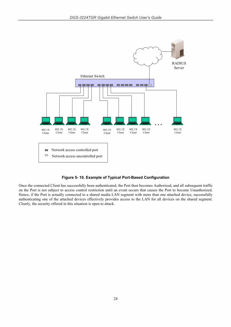
DGS-3224TGR Gigabit Ethernet Switch User’s Guide
24
…802.1XClient
802.1XClient
802.1XClient
802.1XClient
802.1XClient
802.1XClient
802.1XClient
802.1XClient
802.1XClient
Network access controlled port
Network access uncontrolled port
RADIUSServer
Ethernet Switch
Figure 5- 10. Example of Typical Port-Based Configuration
Once the connected Client has successfully been authenticated, the Port then becomes Authorized, and all subsequent traffic on the Port is not subject to access control restriction until an event occurs that causes the Port to become Unauthorized. Hence, if the Port is actually connected to a shared media LAN segment with more than one attached device, successfully authenticating one of the attached devices effectively provides access to the LAN for all devices on the shared segment. Clearly, the security offered in this situation is open to attack.
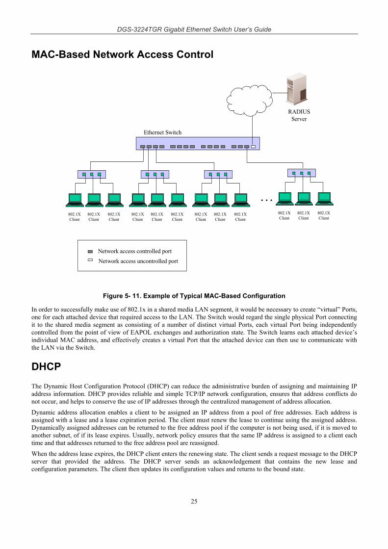
DGS-3224TGR Gigabit Ethernet Switch User’s Guide
25
MAC-Based Network Access Control
802.1XClient
Network access controlled port
Network access uncontrolled port
RADIUSServer
Ethernet Switch
802.1XClient
802.1XClient
802.1XClient
802.1XClient
802.1XClient
802.1XClient
802.1XClient
802.1XClient
802.1XClient
802.1XClient
802.1XClient
…
Figure 5- 11. Example of Typical MAC-Based Configuration
In order to successfully make use of 802.1x in a shared media LAN segment, it would be necessary to create “virtual” Ports, one for each attached device that required access to the LAN. The Switch would regard the single physical Port connecting it to the shared media segment as consisting of a number of distinct virtual Ports, each virtual Port being independently controlled from the point of view of EAPOL exchanges and authorization state. The Switch learns each attached device’s individual MAC address, and effectively creates a virtual Port that the attached device can then use to communicate with the LAN via the Switch.
DHCP
The Dynamic Host Configuration Protocol (DHCP) can reduce the administrative burden of assigning and maintaining IP address information. DHCP provides reliable and simple TCP/IP network configuration, ensures that address conflicts do not occur, and helps to conserve the use of IP addresses through the centralized management of address allocation.
Dynamic address allocation enables a client to be assigned an IP address from a pool of free addresses. Each address is assigned with a lease and a lease expiration period. The client must renew the lease to continue using the assigned address. Dynamically assigned addresses can be returned to the free address pool if the computer is not being used, if it is moved to another subnet, of if its lease expires. Usually, network policy ensures that the same IP address is assigned to a client each time and that addresses returned to the free address pool are reassigned.
When the address lease expires, the DHCP client enters the renewing state. The client sends a request message to the DHCP server that provided the address. The DHCP server sends an acknowledgement that contains the new lease and configuration parameters. The client then updates its configuration values and returns to the bound state.
DGS-3224TGR Gigabit Ethernet Switch User’s Guide
26
When the DHCP client is in the renewing state, it must release its address immediately in the rare event that the DHCP server sends a negative acknowledgment. The DHCP server sends this message to inform a client that it has incorrect configuration information, forcing it to release its current address and acquire new information.
If the DHCP client cannot successfully renew its lease, the client enters a rebinding state. The client then sends a request message to all DHCP servers in its range, attempting to renew its lease. Any DHCP server that can extend the lease sends an acknowledgement containing the extended lease and updated configuration information. If the lease expires or if a DHCP server responds with a negative acknowledgement, the client must release its current configuration, and then return to the initializing state.
If the DHCP client uses more than one network adapter to connect to multiple networks, this protocol is followed for each adapter that the user wants to configure for TCP/IP. Multi-homed systems are selectively configured for any combination of the system’s interfaces.
When a DHCP-enabled computer is restarted, it sends a message to the DHCP server with its current configuration information. The DHCP server either confirms this configuration or sends a negative reply so that the client must begin the initializing state again. System startup might, therefore, result in a new IP address for a client computer, but neither the user nor the network administrator has to take any action in the configuration process.
Before loading TCP/IP with an address acquired from the DHCP server, DHCP clients check for an IP address conflict by sending an Address Resolution Protocol (ARP) request containing the address. If a conflict is found, TCP/IP does not start, and the user receives an error message. The conflicting address should be removed for the list of active leases or it should be excluded until the conflict is identified and resolved.
DGS-3224TGR Gigabit Ethernet Switch User’s Guide
27
6 Web-Based Network Management
Introduction
The DGS-3224TGR offers an embedded Web-based (HTML) interface allowing users to manage the switch from anywhere on the network through a standard browser, such as Opera, Netscape Navigator/Communicator, or Microsoft Internet Explorer. The Web browser acts as a universal access tool and can communicate directly with the switch using the HTTP protocol. Your browser window may vary with the screen shots (pictures) in this guide.
The Web-based management module and the Console program (and Telnet) are different ways to access the same internal switching software and configure it. Thus, all settings encountered in Web-based management are the same as those found in the console program.
NOTE: This Web-based Management Module does not accept Chinese language input (or other languages requiring 2 bytes per character).
NOTE: It is necessary to download Java Runtime Environment 1.4.2 to display the Topology windows located in the Single IP Management folder.
Getting Started
The first step in getting started in using Web-based management for your switch is to secure a browser. A Web browser is a program that allows a person to read hypertext, for example, Opera, Netscape Navigator, or Microsoft Internet Explorer. Follow the installation instructions for the browser.
The second and last step is to configure the IP interface of the switch. This should be done manually through a console (see the Configure IP Address section in the “Using The Console Interface” chapter).
You are now ready to begin managing your switch by simply running the browser installed on your computer and pointing it to the IP address you have defined for the device. The URL in the address bar should read something like: http://123.123.123.123, where the numbers 123 represent the IP address of the switch. Please note that the proxy for session connection should be turned off.
Depending on which browser you are using, a dialog box similar to the following will open:
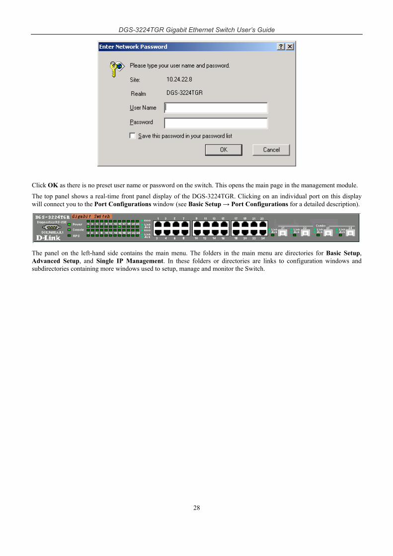
DGS-3224TGR Gigabit Ethernet Switch User’s Guide
28
Click OK as there is no preset user name or password on the switch. This opens the main page in the management module.
The top panel shows a real-time front panel display of the DGS-3224TGR. Clicking on an individual port on this display will connect you to the Port Configurations window (see Basic Setup → Port Configurations for a detailed description).
The panel on the left-hand side contains the main menu. The folders in the main menu are directories for Basic Setup, Advanced Setup, and Single IP Management. In these folders or directories are links to configuration windows and subdirectories containing more windows used to setup, manage and monitor the Switch.
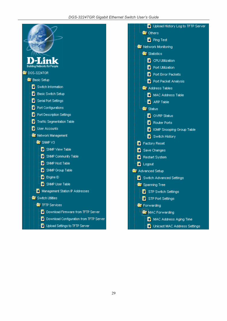
DGS-3224TGR Gigabit Ethernet Switch User’s Guide
29
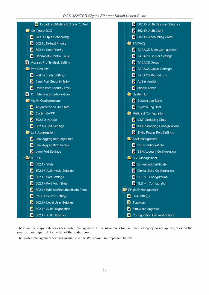
DGS-3224TGR Gigabit Ethernet Switch User’s Guide
30
These are the major categories for switch management. If the sub-menus for each main category do not appear, click on the small square hyperlink to the left of the folder icon.
The switch management features available in the Web-based are explained below.
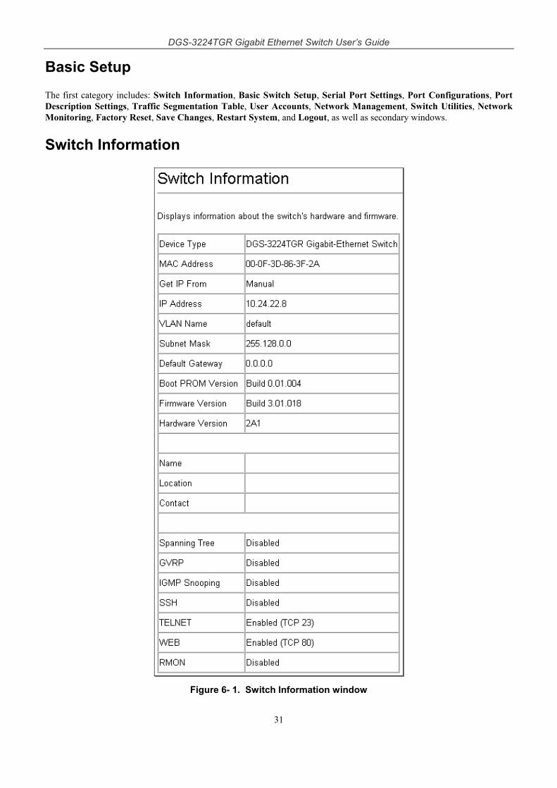
DGS-3224TGR Gigabit Ethernet Switch User’s Guide
31
Basic Setup
The first category includes: Switch Information, Basic Switch Setup, Serial Port Settings, Port Configurations, Port Description Settings, Traffic Segmentation Table, User Accounts, Network Management, Switch Utilities, Network Monitoring, Factory Reset, Save Changes, Restart System, and Logout, as well as secondary windows.
Switch Information
Figure 6- 1. Switch Information window
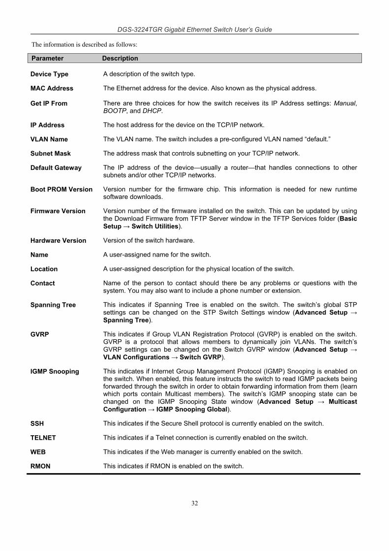
DGS-3224TGR Gigabit Ethernet Switch User’s Guide
32
The information is described as follows:
Parameter Description
Device Type A description of the switch type.
MAC Address The Ethernet address for the device. Also known as the physical address.
Get IP From There are three choices for how the switch receives its IP Address settings: Manual, BOOTP, and DHCP.
IP Address The host address for the device on the TCP/IP network.
VLAN Name The VLAN name. The switch includes a pre-configured VLAN named “default.”
Subnet Mask The address mask that controls subnetting on your TCP/IP network.
Default Gateway The IP address of the device—usually a router—that handles connections to other subnets and/or other TCP/IP networks.
Boot PROM Version Version number for the firmware chip. This information is needed for new runtime software downloads.
Firmware Version Version number of the firmware installed on the switch. This can be updated by using the Download Firmware from TFTP Server window in the TFTP Services folder (Basic Setup → Switch Utilities).
Hardware Version Version of the switch hardware.
Name A user-assigned name for the switch.
Location A user-assigned description for the physical location of the switch.
Contact Name of the person to contact should there be any problems or questions with the system. You may also want to include a phone number or extension.
Spanning Tree This indicates if Spanning Tree is enabled on the switch. The switch’s global STP settings can be changed on the STP Switch Settings window (Advanced Setup → Spanning Tree).
GVRP This indicates if Group VLAN Registration Protocol (GVRP) is enabled on the switch. GVRP is a protocol that allows members to dynamically join VLANs. The switch’s GVRP settings can be changed on the Switch GVRP window (Advanced Setup → VLAN Configurations → Switch GVRP).
IGMP Snooping This indicates if Internet Group Management Protocol (IGMP) Snooping is enabled on the switch. When enabled, this feature instructs the switch to read IGMP packets being forwarded through the switch in order to obtain forwarding information from them (learn which ports contain Multicast members). The switch’s IGMP snooping state can be changed on the IGMP Snooping State window (Advanced Setup → Multicast Configuration → IGMP Snooping Global).
SSH This indicates if the Secure Shell protocol is currently enabled on the switch.
TELNET This indicates if a Telnet connection is currently enabled on the switch.
WEB This indicates if the Web manager is currently enabled on the switch.
RMON This indicates if RMON is enabled on the switch.
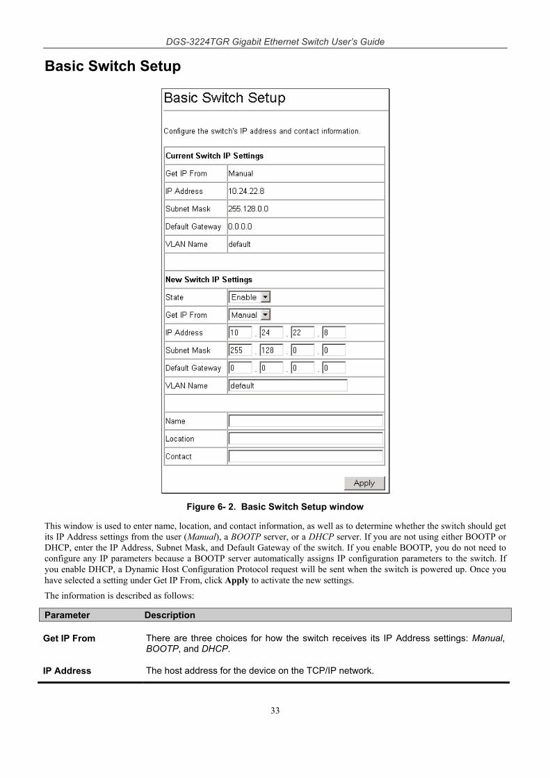
DGS-3224TGR Gigabit Ethernet Switch User’s Guide
33
Basic Switch Setup
Figure 6- 2. Basic Switch Setup window
This window is used to enter name, location, and contact information, as well as to determine whether the switch should get its IP Address settings from the user (Manual), a BOOTP server, or a DHCP server. If you are not using either BOOTP or DHCP, enter the IP Address, Subnet Mask, and Default Gateway of the switch. If you enable BOOTP, you do not need to configure any IP parameters because a BOOTP server automatically assigns IP configuration parameters to the switch. If you enable DHCP, a Dynamic Host Configuration Protocol request will be sent when the switch is powered up. Once you have selected a setting under Get IP From, click Apply to activate the new settings.
The information is described as follows:
Parameter Description
Get IP From There are three choices for how the switch receives its IP Address settings: Manual, BOOTP, and DHCP.
IP Address The host address for the device on the TCP/IP network.
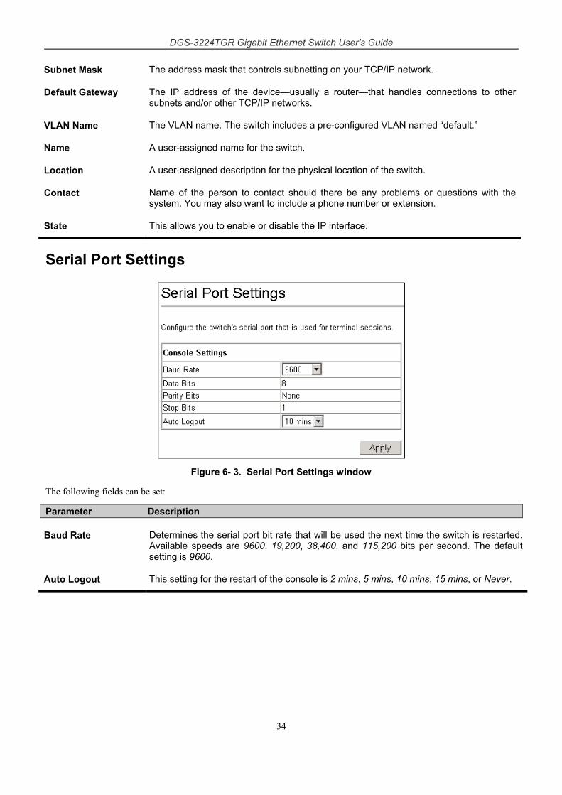
DGS-3224TGR Gigabit Ethernet Switch User’s Guide
34
Subnet Mask The address mask that controls subnetting on your TCP/IP network.
Default Gateway The IP address of the device—usually a router—that handles connections to other subnets and/or other TCP/IP networks.
VLAN Name The VLAN name. The switch includes a pre-configured VLAN named “default.”
Name A user-assigned name for the switch.
Location A user-assigned description for the physical location of the switch.
Contact Name of the person to contact should there be any problems or questions with the system. You may also want to include a phone number or extension.
State This allows you to enable or disable the IP interface.
Serial Port Settings
Figure 6- 3. Serial Port Settings window
The following fields can be set:
Parameter Description
Baud Rate Determines the serial port bit rate that will be used the next time the switch is restarted. Available speeds are 9600, 19,200, 38,400, and 115,200 bits per second. The default setting is 9600.
Auto Logout This setting for the restart of the console is 2 mins, 5 mins, 10 mins, 15 mins, or Never.
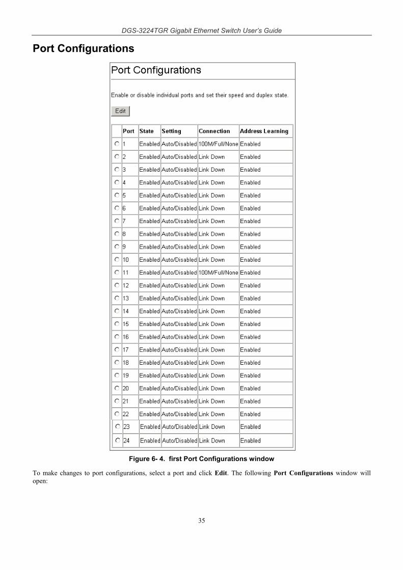
DGS-3224TGR Gigabit Ethernet Switch User’s Guide
35
Port Configurations
Figure 6- 4. first Port Configurations window
To make changes to port configurations, select a port and click Edit. The following Port Configurations window will open:
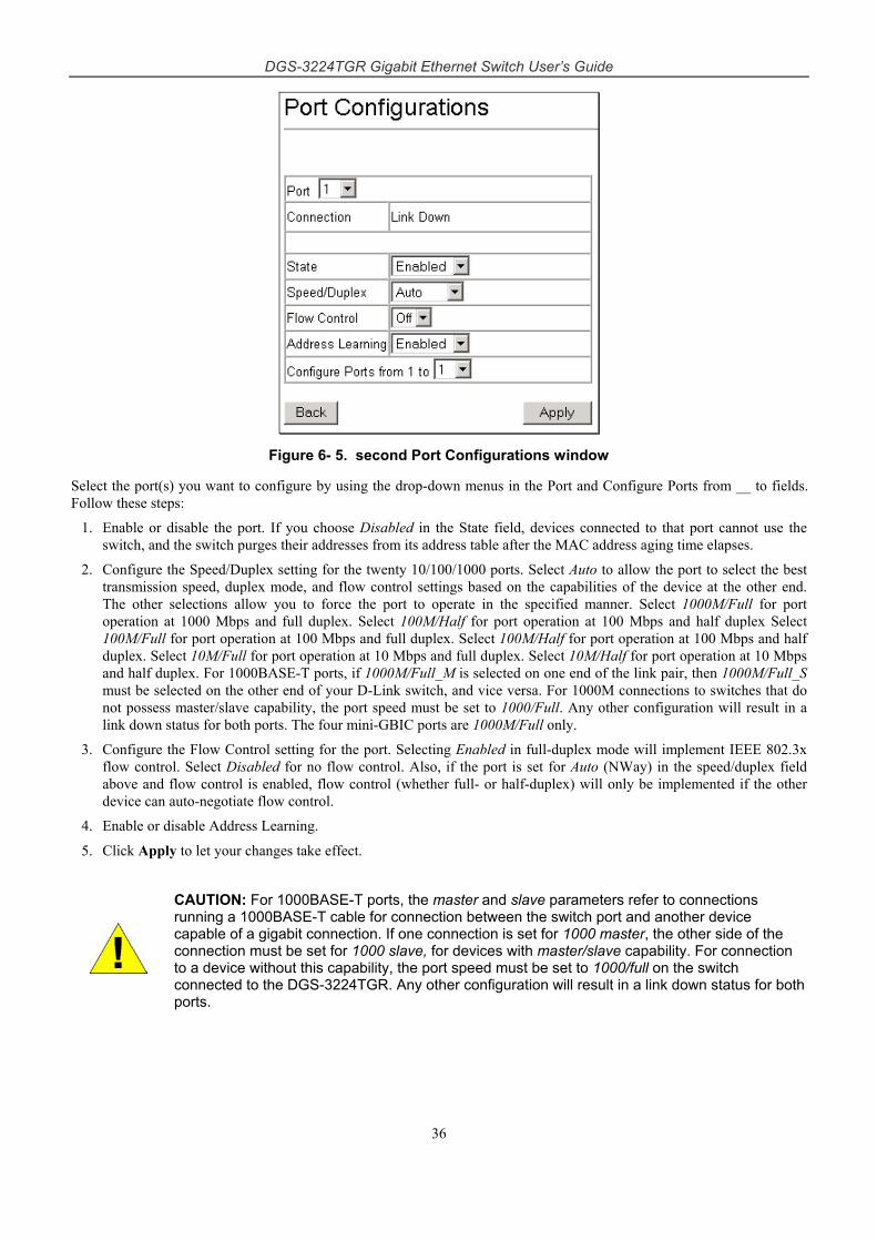
DGS-3224TGR Gigabit Ethernet Switch User’s Guide
36
Figure 6- 5. second Port Configurations window
Select the port(s) you want to configure by using the drop-down menus in the Port and Configure Ports from __ to fields. Follow these steps:
1. Enable or disable the port. If you choose Disabled in the State field, devices connected to that port cannot use the switch, and the switch purges their addresses from its address table after the MAC address aging time elapses.
2. Configure the Speed/Duplex setting for the twenty 10/100/1000 ports. Select Auto to allow the port to select the best transmission speed, duplex mode, and flow control settings based on the capabilities of the device at the other end. The other selections allow you to force the port to operate in the specified manner. Select 1000M/Full for port operation at 1000 Mbps and full duplex. Select 100M/Half for port operation at 100 Mbps and half duplex Select 100M/Full for port operation at 100 Mbps and full duplex. Select 100M/Half for port operation at 100 Mbps and half duplex. Select 10M/Full for port operation at 10 Mbps and full duplex. Select 10M/Half for port operation at 10 Mbps and half duplex. For 1000BASE-T ports, if 1000M/Full_M is selected on one end of the link pair, then 1000M/Full_S must be selected on the other end of your D-Link switch, and vice versa. For 1000M connections to switches that do not possess master/slave capability, the port speed must be set to 1000/Full. Any other configuration will result in a link down status for both ports. The four mini-GBIC ports are 1000M/Full only.
3. Configure the Flow Control setting for the port. Selecting Enabled in full-duplex mode will implement IEEE 802.3x flow control. Select Disabled for no flow control. Also, if the port is set for Auto (NWay) in the speed/duplex field above and flow control is enabled, flow control (whether full- or half-duplex) will only be implemented if the other device can auto-negotiate flow control.
4. Enable or disable Address Learning.
5. Click Apply to let your changes take effect.
CAUTION: For 1000BASE-T ports, the master and slave parameters refer to connections running a 1000BASE-T cable for connection between the switch port and another device capable of a gigabit connection. If one connection is set for 1000 master, the other side of the connection must be set for 1000 slave, for devices with master/slave capability. For connection to a device without this capability, the port speed must be set to 1000/full on the switch connected to the DGS-3224TGR. Any other configuration will result in a link down status for both ports.
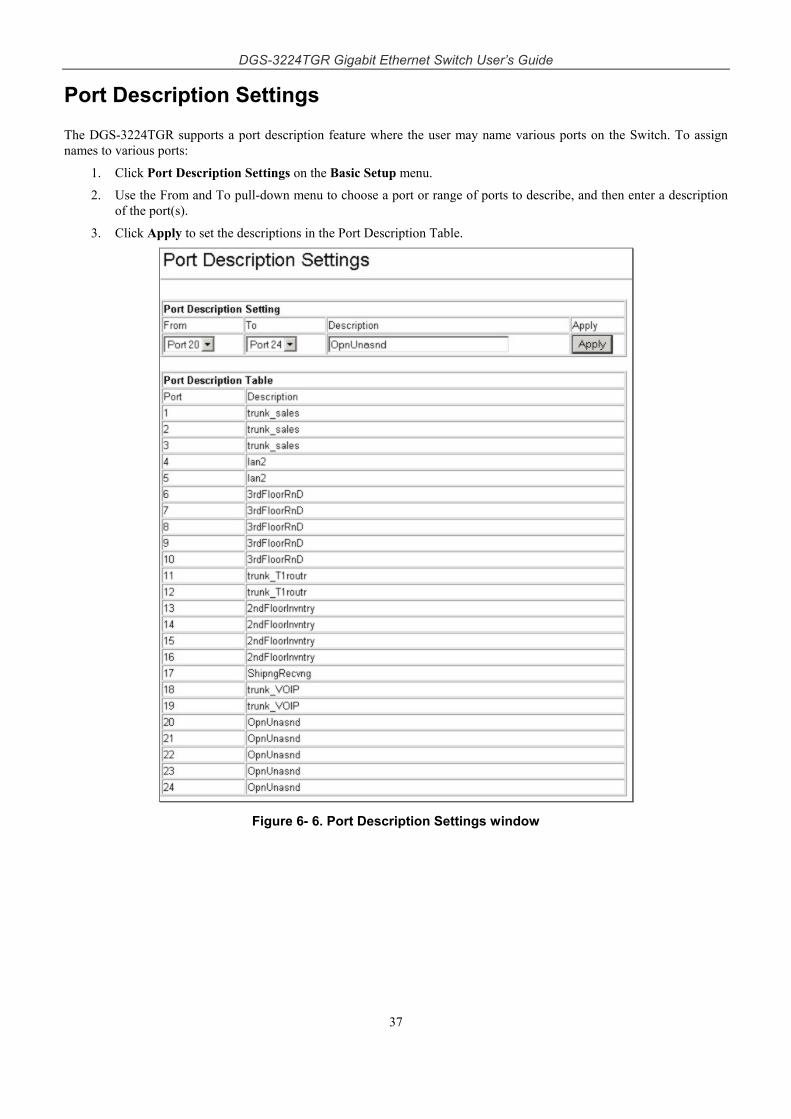
DGS-3224TGR Gigabit Ethernet Switch User’s Guide
37
Port Description Settings
The DGS-3224TGR supports a port description feature where the user may name various ports on the Switch. To assign names to various ports:
1. Click Port Description Settings on the Basic Setup menu.
2. Use the From and To pull-down menu to choose a port or range of ports to describe, and then enter a description of the port(s).
3. Click Apply to set the descriptions in the Port Description Table.
Figure 6- 6. Port Description Settings window
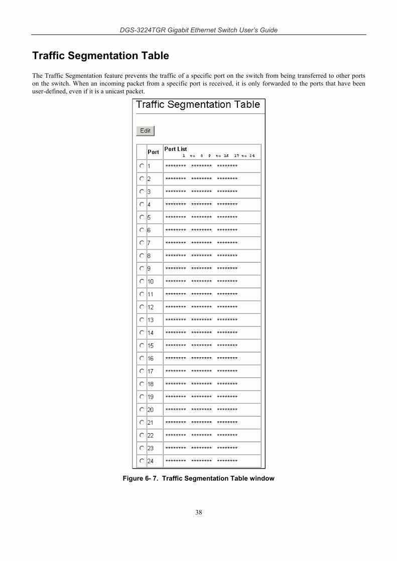
DGS-3224TGR Gigabit Ethernet Switch User’s Guide
38
Traffic Segmentation Table
The Traffic Segmentation feature prevents the traffic of a specific port on the switch from being transferred to other ports on the switch. When an incoming packet from a specific port is received, it is only forwarded to the ports that have been user-defined, even if it is a unicast packet.
Figure 6- 7. Traffic Segmentation Table window
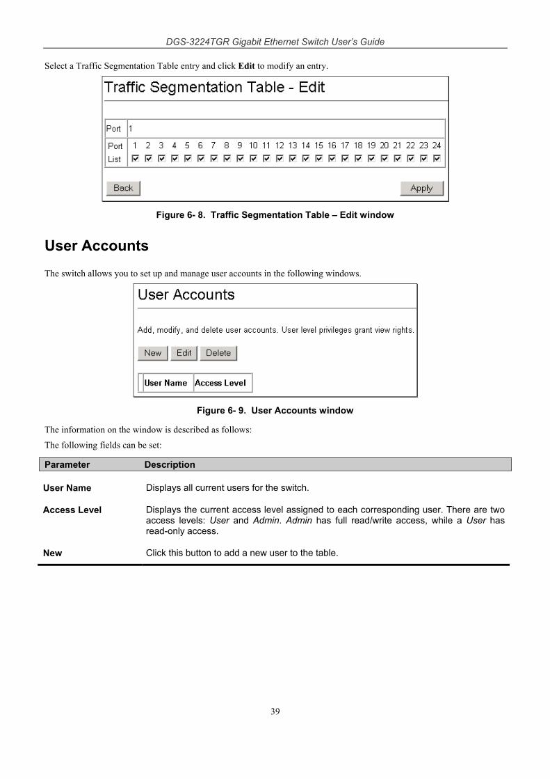
DGS-3224TGR Gigabit Ethernet Switch User’s Guide
39
Select a Traffic Segmentation Table entry and click Edit to modify an entry.
Figure 6- 8. Traffic Segmentation Table – Edit window
User Accounts
The switch allows you to set up and manage user accounts in the following windows.
Figure 6- 9. User Accounts window
The information on the window is described as follows:
The following fields can be set:
Parameter Description
User Name Displays all current users for the switch.
Access Level Displays the current access level assigned to each corresponding user. There are two access levels: User and Admin. Admin has full read/write access, while a User has read-only access.
New Click this button to add a new user to the table.
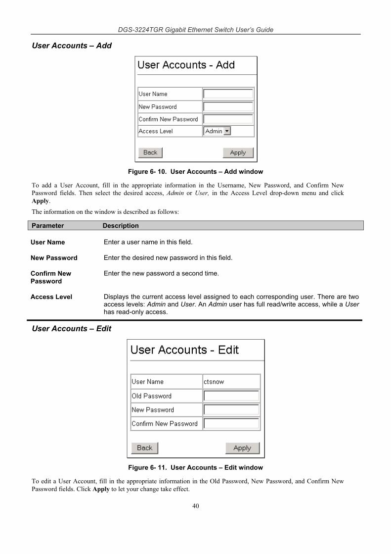
DGS-3224TGR Gigabit Ethernet Switch User’s Guide
40
User Accounts – Add
Figure 6- 10. User Accounts – Add window
To add a User Account, fill in the appropriate information in the Username, New Password, and Confirm New Password fields. Then select the desired access, Admin or User, in the Access Level drop-down menu and click Apply.
The information on the window is described as follows:
Parameter Description
User Name Enter a user name in this field.
New Password Enter the desired new password in this field.
Confirm New Password
Enter the new password a second time.
Access Level Displays the current access level assigned to each corresponding user. There are two access levels: Admin and User. An Admin user has full read/write access, while a User has read-only access.
User Accounts – Edit
Figure 6- 11. User Accounts – Edit window
To edit a User Account, fill in the appropriate information in the Old Password, New Password, and Confirm New Password fields. Click Apply to let your change take effect.
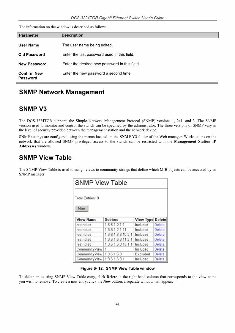
DGS-3224TGR Gigabit Ethernet Switch User’s Guide
41
The information on the window is described as follows:
Parameter Description
User Name The user name being edited.
Old Password Enter the last password used in this field.
New Password Enter the desired new password in this field.
Confirm New Password
Enter the new password a second time.
SNMP Network Management
SNMP V3
The DGS-3224TGR supports the Simple Network Management Protocol (SNMP) versions 1, 2c1, and 3. The SNMP version used to monitor and control the switch can be specified by the administrator. The three versions of SNMP vary in the level of security provided between the management station and the network device.
SNMP settings are configured using the menus located on the SNMP V3 folder of the Web manager. Workstations on the network that are allowed SNMP privileged access to the switch can be restricted with the Management Station IP Addresses window.
SNMP View Table
The SNMP View Table is used to assign views to community strings that define which MIB objects can be accessed by an SNMP manager.
Figure 6- 12. SNMP View Table window
To delete an existing SNMP View Table entry, click Delete in the right-hand column that corresponds to the view name you wish to remove. To create a new entry, click the New button, a separate window will appear.
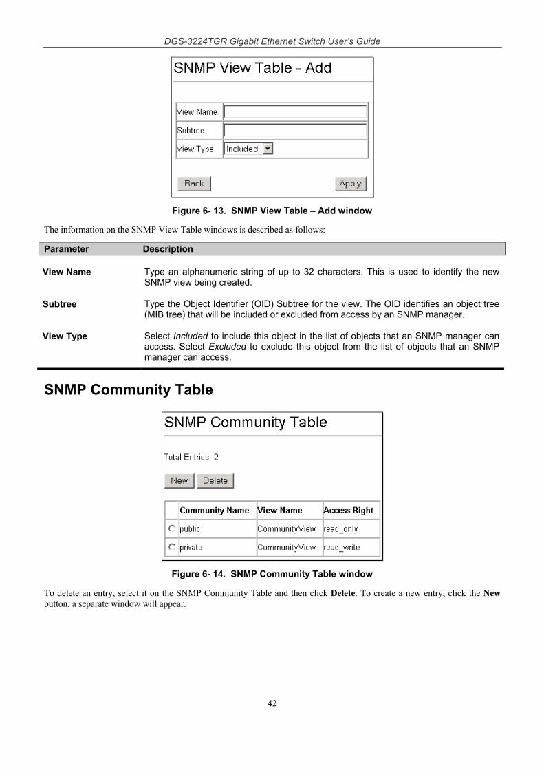
DGS-3224TGR Gigabit Ethernet Switch User’s Guide
42
Figure 6- 13. SNMP View Table – Add window
The information on the SNMP View Table windows is described as follows:
Parameter Description
View Name Type an alphanumeric string of up to 32 characters. This is used to identify the new SNMP view being created.
Subtree Type the Object Identifier (OID) Subtree for the view. The OID identifies an object tree (MIB tree) that will be included or excluded from access by an SNMP manager.
View Type Select Included to include this object in the list of objects that an SNMP manager can access. Select Excluded to exclude this object from the list of objects that an SNMP manager can access.
SNMP Community Table
Figure 6- 14. SNMP Community Table window
To delete an entry, select it on the SNMP Community Table and then click Delete. To create a new entry, click the New button, a separate window will appear.

DGS-3224TGR Gigabit Ethernet Switch User’s Guide
43
Figure 6- 15. SNMP Community Table – Add window
SNMP Host Table
Use the SNMP Host Table to set up trap recipients.
Figure 6- 16. SNMP Host Table window
To delete an existing entry, click the selection button in the right-hand column that corresponds to the port you want to remove and then click Delete. To create a new entry, click the New button, a separate window will appear.
Figure 6- 17. SNMP Host Table – Add window
The following parameters are used in the SNMP Host Table windows:
Parameter Description
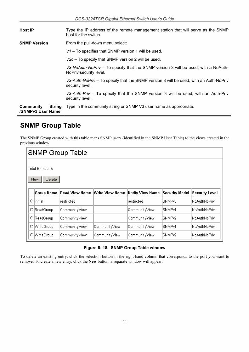
DGS-3224TGR Gigabit Ethernet Switch User’s Guide
44
Host IP Type the IP address of the remote management station that will serve as the SNMP host for the switch.
SNMP Version From the pull-down menu select:
V1 – To specifies that SNMP version 1 will be used.
V2c – To specify that SNMP version 2 will be used.
V3-NoAuth-NoPriv – To specify that the SNMP version 3 will be used, with a NoAuth-NoPriv security level.
V3-Auth-NoPriv – To specify that the SNMP version 3 will be used, with an Auth-NoPriv security level.
V3-Auth-Priv – To specify that the SNMP version 3 will be used, with an Auth-Priv security level.
Community String /SNMPv3 User Name
Type in the community string or SNMP V3 user name as appropriate.
SNMP Group Table
The SNMP Group created with this table maps SNMP users (identified in the SNMP User Table) to the views created in the previous window.
Figure 6- 18. SNMP Group Table window
To delete an existing entry, click the selection button in the right-hand column that corresponds to the port you want to remove. To create a new entry, click the New button, a separate window will appear.
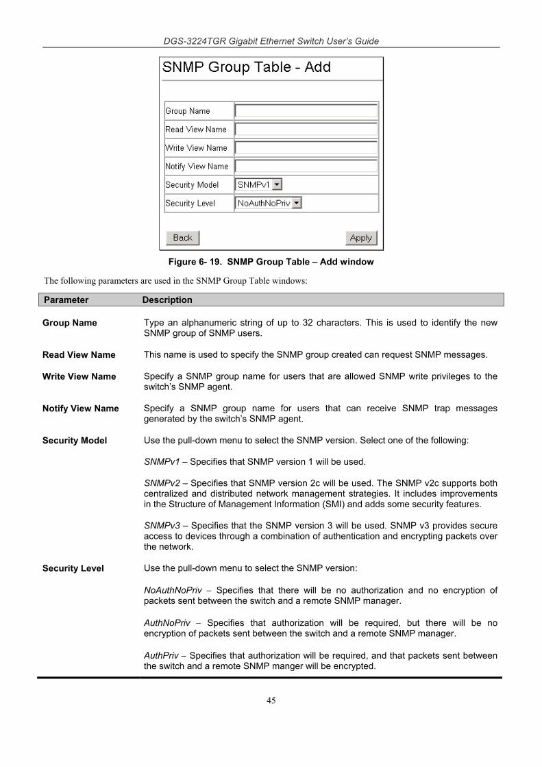
DGS-3224TGR Gigabit Ethernet Switch User’s Guide
45
Figure 6- 19. SNMP Group Table – Add window
The following parameters are used in the SNMP Group Table windows:
Parameter Description
Group Name Type an alphanumeric string of up to 32 characters. This is used to identify the new SNMP group of SNMP users.
Read View Name This name is used to specify the SNMP group created can request SNMP messages.
Write View Name Specify a SNMP group name for users that are allowed SNMP write privileges to the switch’s SNMP agent.
Notify View Name Specify a SNMP group name for users that can receive SNMP trap messages generated by the switch’s SNMP agent.
Security Model Use the pull-down menu to select the SNMP version. Select one of the following:
SNMPv1 – Specifies that SNMP version 1 will be used.
SNMPv2 – Specifies that SNMP version 2c will be used. The SNMP v2c supports both centralized and distributed network management strategies. It includes improvements in the Structure of Management Information (SMI) and adds some security features.
SNMPv3 – Specifies that the SNMP version 3 will be used. SNMP v3 provides secure access to devices through a combination of authentication and encrypting packets over the network.
Security Level Use the pull-down menu to select the SNMP version:
NoAuthNoPriv − Specifies that there will be no authorization and no encryption of packets sent between the switch and a remote SNMP manager.
AuthNoPriv − Specifies that authorization will be required, but there will be no encryption of packets sent between the switch and a remote SNMP manager.
AuthPriv − Specifies that authorization will be required, and that packets sent between the switch and a remote SNMP manger will be encrypted.
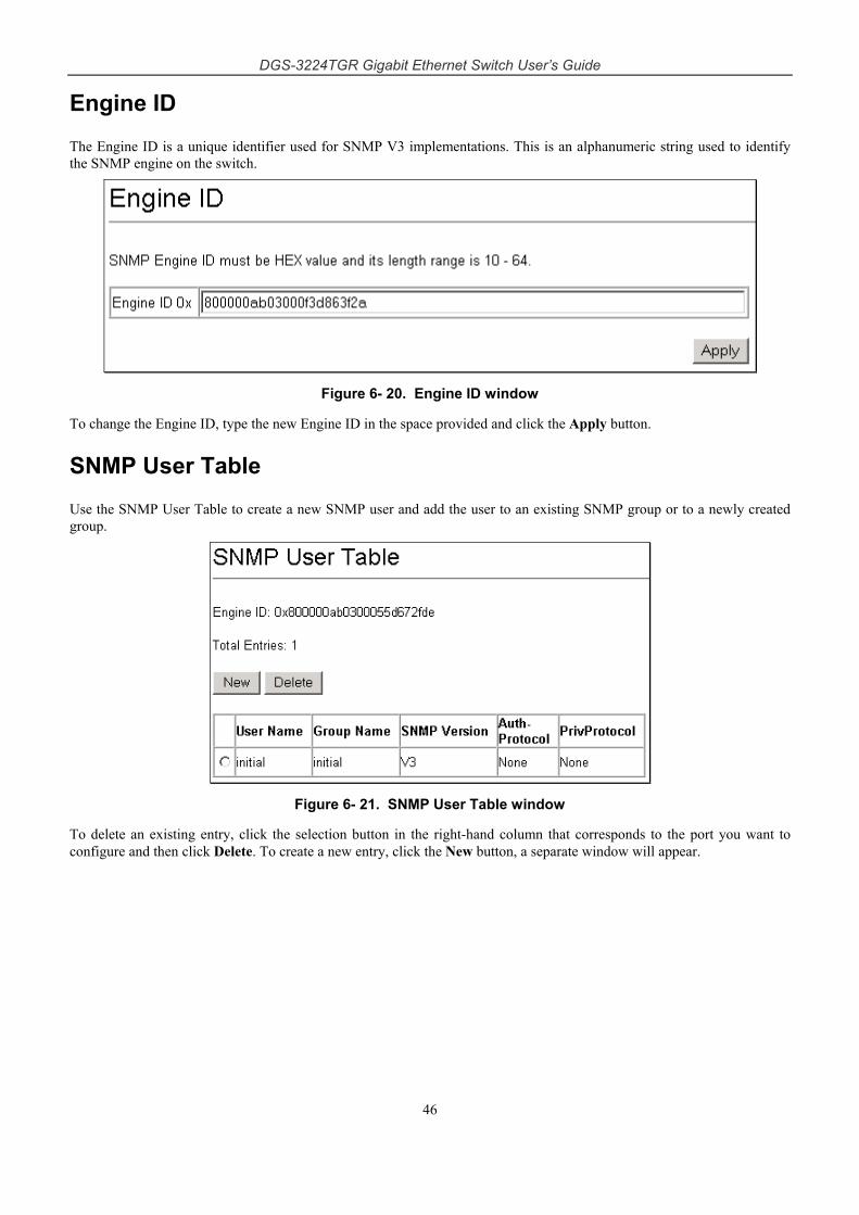
DGS-3224TGR Gigabit Ethernet Switch User’s Guide
46
Engine ID
The Engine ID is a unique identifier used for SNMP V3 implementations. This is an alphanumeric string used to identify the SNMP engine on the switch.
Figure 6- 20. Engine ID window
To change the Engine ID, type the new Engine ID in the space provided and click the Apply button.
SNMP User Table
Use the SNMP User Table to create a new SNMP user and add the user to an existing SNMP group or to a newly created group.
Figure 6- 21. SNMP User Table window
To delete an existing entry, click the selection button in the right-hand column that corresponds to the port you want to configure and then click Delete. To create a new entry, click the New button, a separate window will appear.
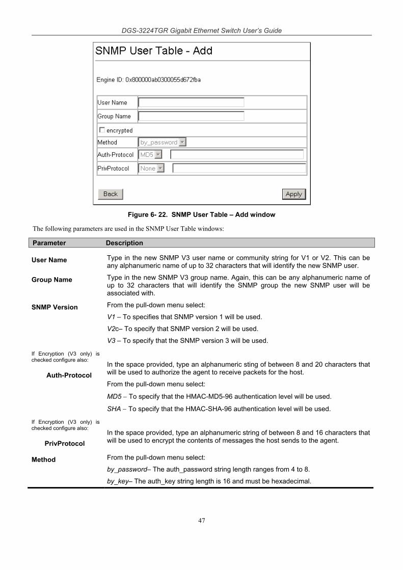
DGS-3224TGR Gigabit Ethernet Switch User’s Guide
47
Figure 6- 22. SNMP User Table – Add window
The following parameters are used in the SNMP User Table windows:
Parameter Description
User Name Type in the new SNMP V3 user name or community string for V1 or V2. This can be any alphanumeric name of up to 32 characters that will identify the new SNMP user.
Group Name Type in the new SNMP V3 group name. Again, this can be any alphanumeric name of up to 32 characters that will identify the SNMP group the new SNMP user will be associated with.
SNMP Version From the pull-down menu select:
V1 – To specifies that SNMP version 1 will be used.
V2c– To specify that SNMP version 2 will be used.
V3 – To specify that the SNMP version 3 will be used.
If Encryption (V3 only) is checked configure also:
Auth-Protocol
In the space provided, type an alphanumeric sting of between 8 and 20 characters that will be used to authorize the agent to receive packets for the host.
From the pull-down menu select:
MD5 − To specify that the HMAC-MD5-96 authentication level will be used.
SHA − To specify that the HMAC-SHA-96 authentication level will be used.
If Encryption (V3 only) is checked configure also:
PrivProtocol
In the space provided, type an alphanumeric string of between 8 and 16 characters that will be used to encrypt the contents of messages the host sends to the agent.
Method From the pull-down menu select:
by_password– The auth_password string length ranges from 4 to 8.
by_key– The auth_key string length is 16 and must be hexadecimal.
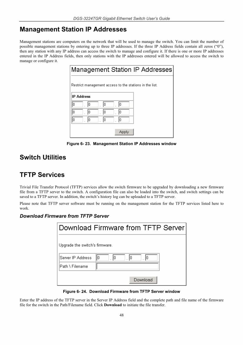
DGS-3224TGR Gigabit Ethernet Switch User’s Guide
48
Management Station IP Addresses
Management stations are computers on the network that will be used to manage the switch. You can limit the number of possible management stations by entering up to three IP addresses. If the three IP Address fields contain all zeros (“0”), then any station with any IP address can access the switch to manage and configure it. If there is one or more IP addresses entered in the IP Address fields, then only stations with the IP addresses entered will be allowed to access the switch to manage or configure it.
Figure 6- 23. Management Station IP Addresses window
Switch Utilities
TFTP Services
Trivial File Transfer Protocol (TFTP) services allow the switch firmware to be upgraded by downloading a new firmware file from a TFTP server to the switch. A configuration file can also be loaded into the switch, and switch settings can be saved to a TFTP server. In addition, the switch’s history log can be uploaded to a TFTP server.
Please note that TFTP server software must be running on the management station for the TFTP services listed here to work.
Download Firmware from TFTP Server
Figure 6- 24. Download Firmware from TFTP Server window
Enter the IP address of the TFTP server in the Server IP Address field and the complete path and file name of the firmware file for the switch in the Path/Filename field. Click Download to initiate the file transfer.
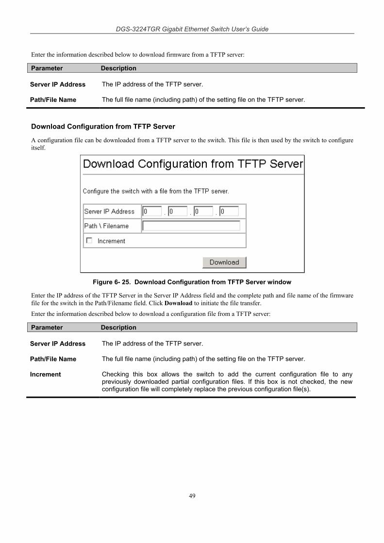
DGS-3224TGR Gigabit Ethernet Switch User’s Guide
49
Enter the information described below to download firmware from a TFTP server:
Parameter Description
Server IP Address The IP address of the TFTP server.
Path/File Name The full file name (including path) of the setting file on the TFTP server.
Download Configuration from TFTP Server
A configuration file can be downloaded from a TFTP server to the switch. This file is then used by the switch to configure itself.
Figure 6- 25. Download Configuration from TFTP Server window
Enter the IP address of the TFTP Server in the Server IP Address field and the complete path and file name of the firmware file for the switch in the Path/Filename field. Click Download to initiate the file transfer.
Enter the information described below to download a configuration file from a TFTP server:
Parameter Description
Server IP Address The IP address of the TFTP server.
Path/File Name The full file name (including path) of the setting file on the TFTP server.
Increment Checking this box allows the switch to add the current configuration file to any previously downloaded partial configuration files. If this box is not checked, the new configuration file will completely replace the previous configuration file(s).
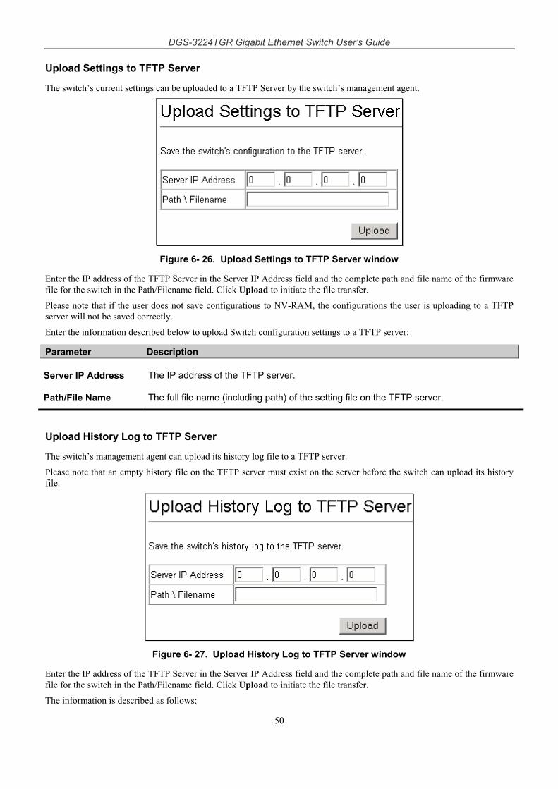
DGS-3224TGR Gigabit Ethernet Switch User’s Guide
50
Upload Settings to TFTP Server
The switch’s current settings can be uploaded to a TFTP Server by the switch’s management agent.
Figure 6- 26. Upload Settings to TFTP Server window
Enter the IP address of the TFTP Server in the Server IP Address field and the complete path and file name of the firmware file for the switch in the Path/Filename field. Click Upload to initiate the file transfer.
Please note that if the user does not save configurations to NV-RAM, the configurations the user is uploading to a TFTP server will not be saved correctly.
Enter the information described below to upload Switch configuration settings to a TFTP server:
Parameter Description
Server IP Address The IP address of the TFTP server.
Path/File Name The full file name (including path) of the setting file on the TFTP server.
Upload History Log to TFTP Server
The switch’s management agent can upload its history log file to a TFTP server.
Please note that an empty history file on the TFTP server must exist on the server before the switch can upload its history file.
Figure 6- 27. Upload History Log to TFTP Server window
Enter the IP address of the TFTP Server in the Server IP Address field and the complete path and file name of the firmware file for the switch in the Path/Filename field. Click Upload to initiate the file transfer.
The information is described as follows:
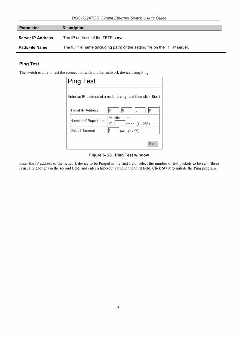
DGS-3224TGR Gigabit Ethernet Switch User’s Guide
51
Parameter Description
Server IP Address The IP address of the TFTP server.
Path/File Name The full file name (including path) of the setting file on the TFTP server.
Ping Test
The switch is able to test the connection with another network device using Ping.
Figure 6- 28. Ping Test window
Enter the IP address of the network device to be Pinged in the first field, select the number of test packets to be sent (three is usually enough) in the second field, and enter a time-out value in the third field. Click Start to initiate the Ping program.
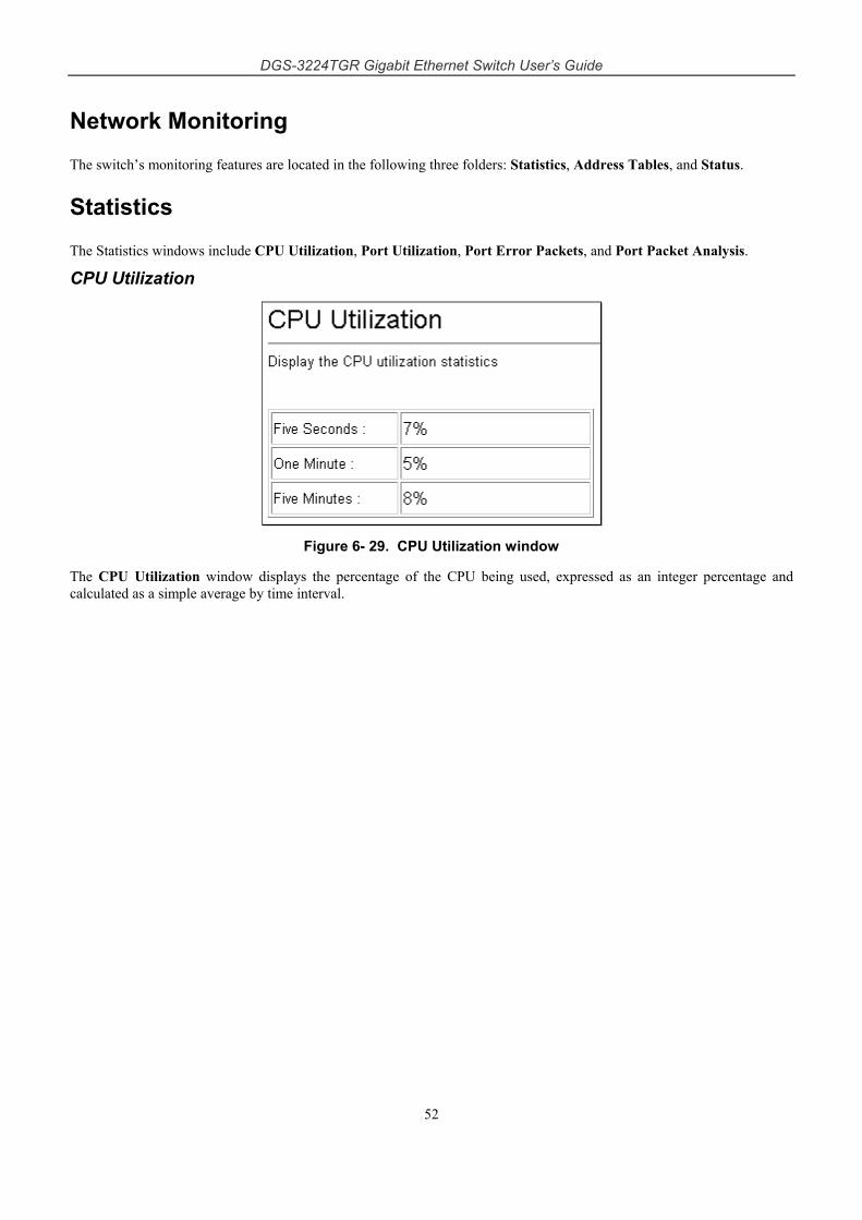
DGS-3224TGR Gigabit Ethernet Switch User’s Guide
52
Network Monitoring
The switch’s monitoring features are located in the following three folders: Statistics, Address Tables, and Status.
Statistics
The Statistics windows include CPU Utilization, Port Utilization, Port Error Packets, and Port Packet Analysis.
CPU Utilization
Figure 6- 29. CPU Utilization window
The CPU Utilization window displays the percentage of the CPU being used, expressed as an integer percentage and calculated as a simple average by time interval.
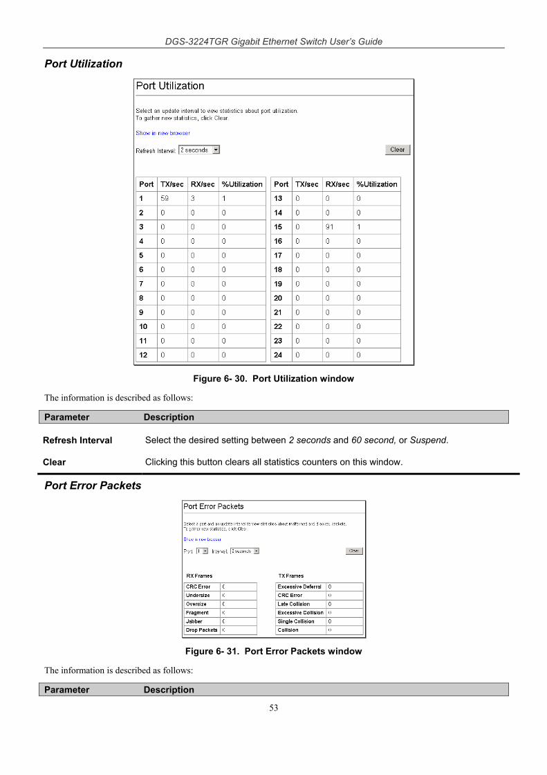
DGS-3224TGR Gigabit Ethernet Switch User’s Guide
53
Port Utilization
Figure 6- 30. Port Utilization window
The information is described as follows:
Parameter Description
Refresh Interval Select the desired setting between 2 seconds and 60 second, or Suspend.
Clear Clicking this button clears all statistics counters on this window.
Port Error Packets
Figure 6- 31. Port Error Packets window
The information is described as follows:
Parameter Description
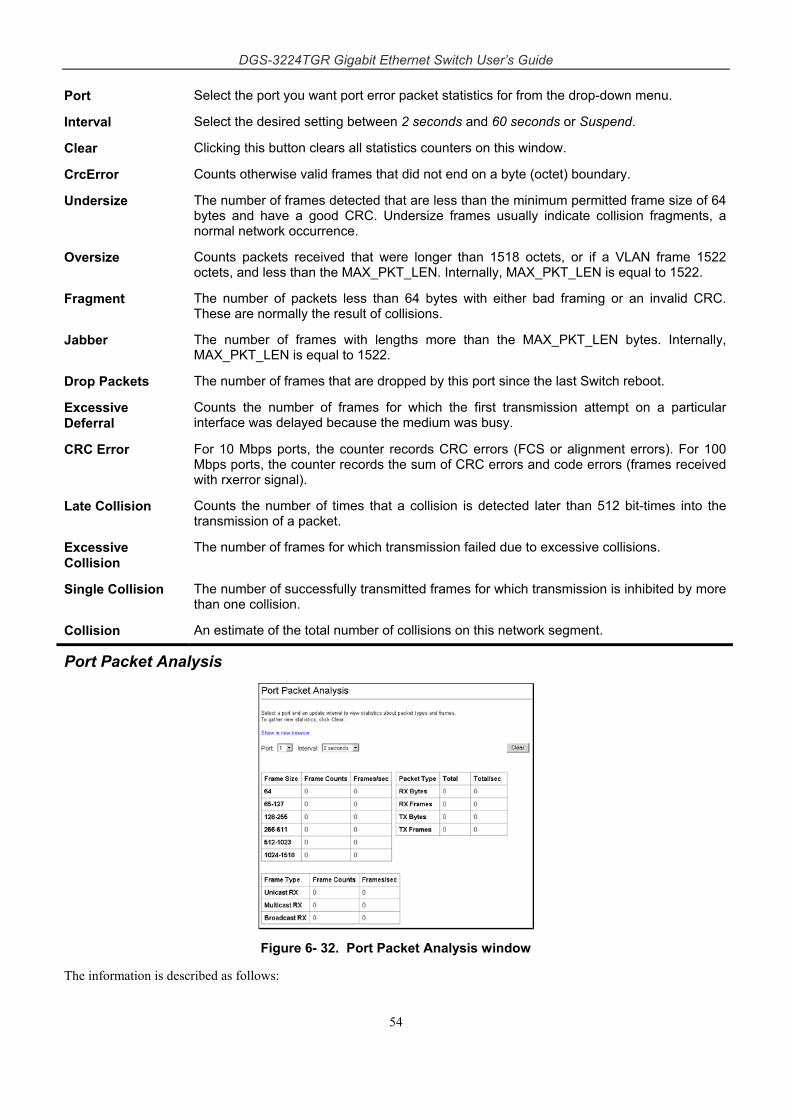
DGS-3224TGR Gigabit Ethernet Switch User’s Guide
54
Port Select the port you want port error packet statistics for from the drop-down menu.
Interval Select the desired setting between 2 seconds and 60 seconds or Suspend.
Clear Clicking this button clears all statistics counters on this window.
CrcError Counts otherwise valid frames that did not end on a byte (octet) boundary.
Undersize The number of frames detected that are less than the minimum permitted frame size of 64 bytes and have a good CRC. Undersize frames usually indicate collision fragments, a normal network occurrence.
Oversize Counts packets received that were longer than 1518 octets, or if a VLAN frame 1522 octets, and less than the MAX_PKT_LEN. Internally, MAX_PKT_LEN is equal to 1522.
Fragment The number of packets less than 64 bytes with either bad framing or an invalid CRC. These are normally the result of collisions.
Jabber The number of frames with lengths more than the MAX_PKT_LEN bytes. Internally, MAX_PKT_LEN is equal to 1522.
Drop Packets The number of frames that are dropped by this port since the last Switch reboot.
Excessive Deferral
Counts the number of frames for which the first transmission attempt on a particular interface was delayed because the medium was busy.
CRC Error For 10 Mbps ports, the counter records CRC errors (FCS or alignment errors). For 100 Mbps ports, the counter records the sum of CRC errors and code errors (frames received with rxerror signal).
Late Collision Counts the number of times that a collision is detected later than 512 bit-times into the transmission of a packet.
Excessive Collision
The number of frames for which transmission failed due to excessive collisions.
Single Collision The number of successfully transmitted frames for which transmission is inhibited by more than one collision.
Collision An estimate of the total number of collisions on this network segment.
Port Packet Analysis
Figure 6- 32. Port Packet Analysis window
The information is described as follows:
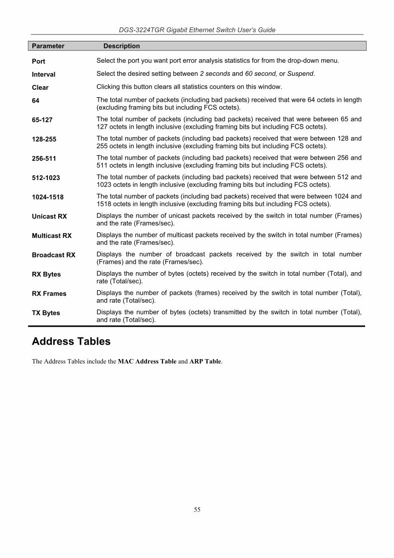
DGS-3224TGR Gigabit Ethernet Switch User’s Guide
55
Parameter Description
Port Select the port you want port error analysis statistics for from the drop-down menu.
Interval Select the desired setting between 2 seconds and 60 second, or Suspend.
Clear Clicking this button clears all statistics counters on this window.
64 The total number of packets (including bad packets) received that were 64 octets in length (excluding framing bits but including FCS octets).
65-127 The total number of packets (including bad packets) received that were between 65 and 127 octets in length inclusive (excluding framing bits but including FCS octets).
128-255 The total number of packets (including bad packets) received that were between 128 and 255 octets in length inclusive (excluding framing bits but including FCS octets).
256-511 The total number of packets (including bad packets) received that were between 256 and 511 octets in length inclusive (excluding framing bits but including FCS octets).
512-1023 The total number of packets (including bad packets) received that were between 512 and 1023 octets in length inclusive (excluding framing bits but including FCS octets).
1024-1518 The total number of packets (including bad packets) received that were between 1024 and 1518 octets in length inclusive (excluding framing bits but including FCS octets).
Unicast RX Displays the number of unicast packets received by the switch in total number (Frames) and the rate (Frames/sec).
Multicast RX Displays the number of multicast packets received by the switch in total number (Frames) and the rate (Frames/sec).
Broadcast RX Displays the number of broadcast packets received by the switch in total number (Frames) and the rate (Frames/sec).
RX Bytes Displays the number of bytes (octets) received by the switch in total number (Total), and rate (Total/sec).
RX Frames Displays the number of packets (frames) received by the switch in total number (Total), and rate (Total/sec).
TX Bytes Displays the number of bytes (octets) transmitted by the switch in total number (Total), and rate (Total/sec).
Address Tables
The Address Tables include the MAC Address Table and ARP Table.
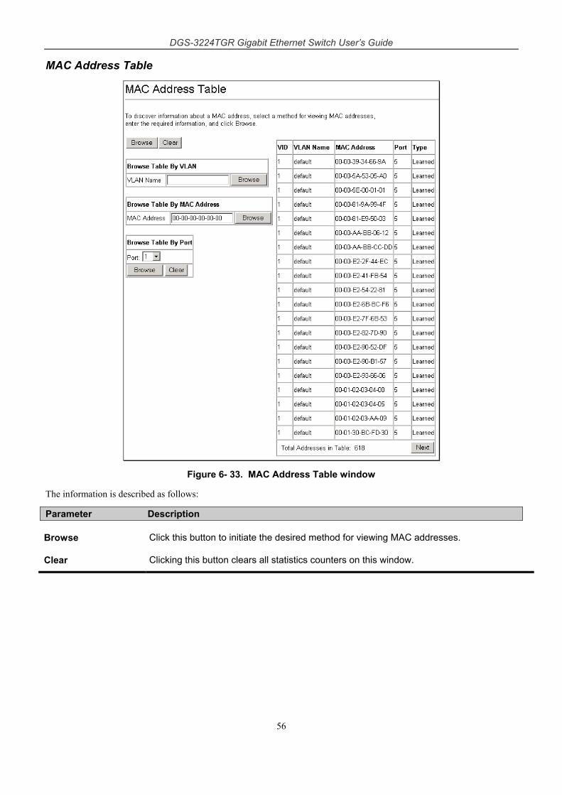
DGS-3224TGR Gigabit Ethernet Switch User’s Guide
56
MAC Address Table
Figure 6- 33. MAC Address Table window
The information is described as follows:
Parameter Description
Browse Click this button to initiate the desired method for viewing MAC addresses.
Clear Clicking this button clears all statistics counters on this window.
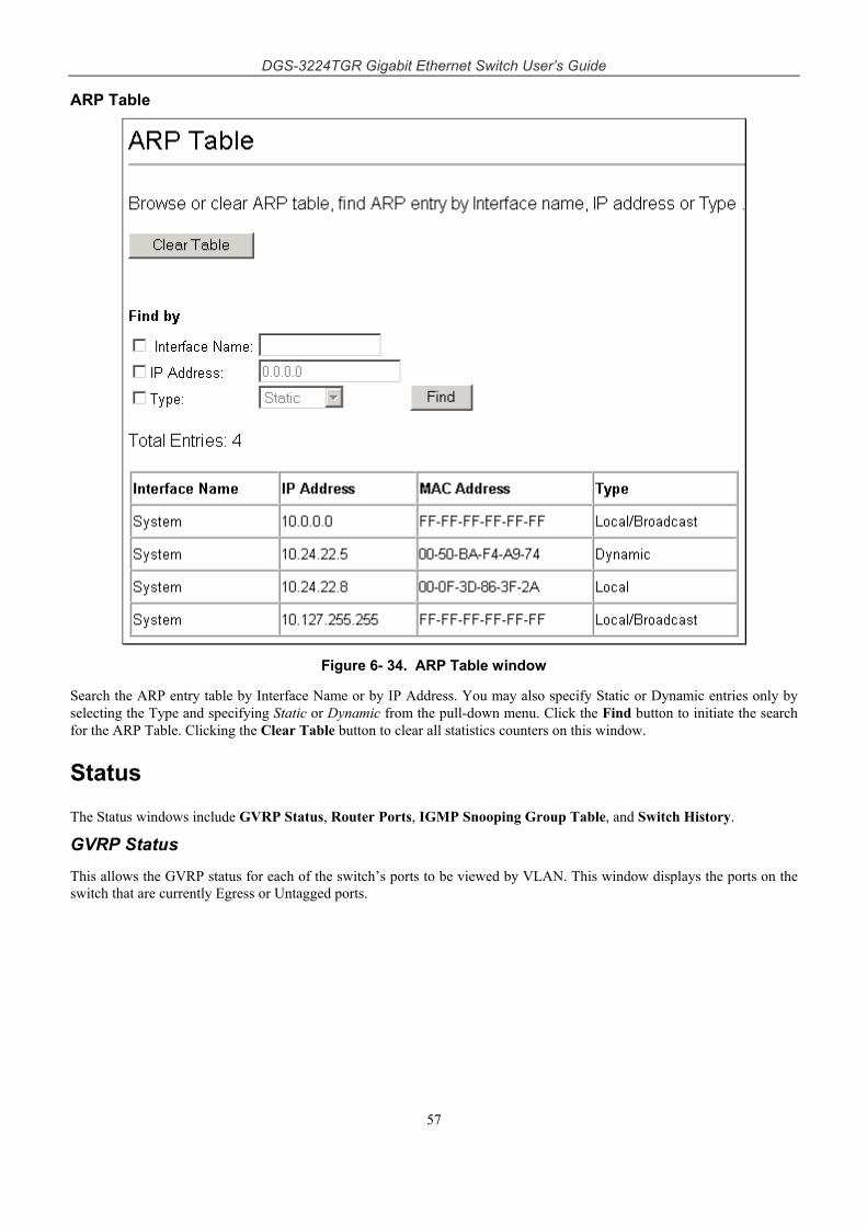
DGS-3224TGR Gigabit Ethernet Switch User’s Guide
57
ARP Table
Figure 6- 34. ARP Table window
Search the ARP entry table by Interface Name or by IP Address. You may also specify Static or Dynamic entries only by selecting the Type and specifying Static or Dynamic from the pull-down menu. Click the Find button to initiate the search for the ARP Table. Clicking the Clear Table button to clear all statistics counters on this window.
Status
The Status windows include GVRP Status, Router Ports, IGMP Snooping Group Table, and Switch History.
GVRP Status This allows the GVRP status for each of the switch’s ports to be viewed by VLAN. This window displays the ports on the switch that are currently Egress or Untagged ports.
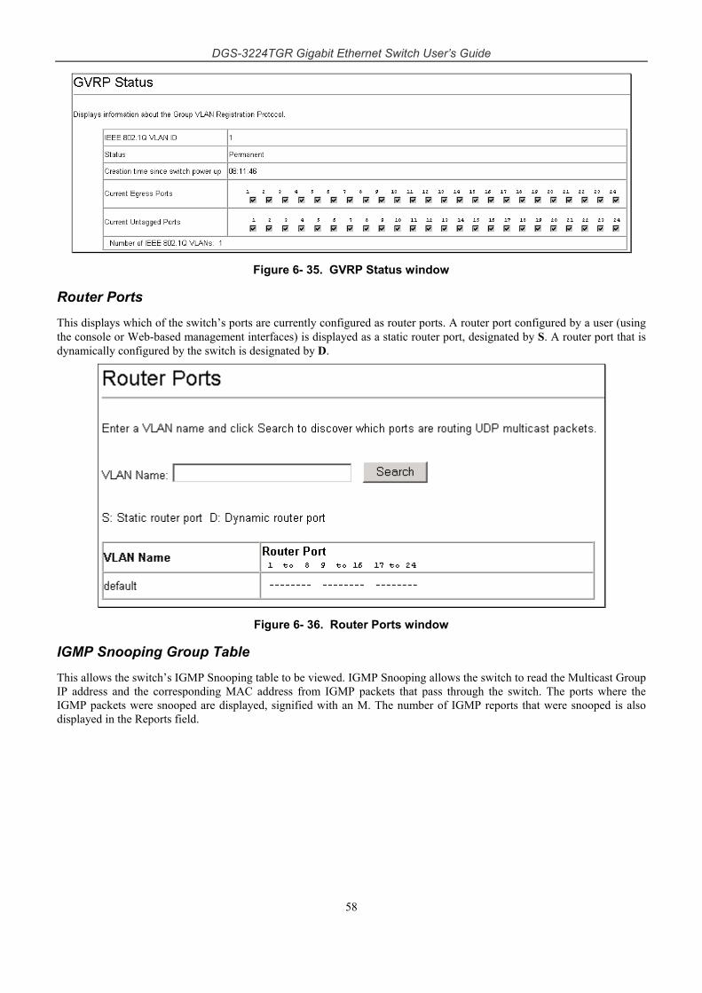
DGS-3224TGR Gigabit Ethernet Switch User’s Guide
58
Figure 6- 35. GVRP Status window
Router Ports This displays which of the switch’s ports are currently configured as router ports. A router port configured by a user (using the console or Web-based management interfaces) is displayed as a static router port, designated by S. A router port that is dynamically configured by the switch is designated by D.
Figure 6- 36. Router Ports window
IGMP Snooping Group Table This allows the switch’s IGMP Snooping table to be viewed. IGMP Snooping allows the switch to read the Multicast Group IP address and the corresponding MAC address from IGMP packets that pass through the switch. The ports where the IGMP packets were snooped are displayed, signified with an M. The number of IGMP reports that were snooped is also displayed in the Reports field.
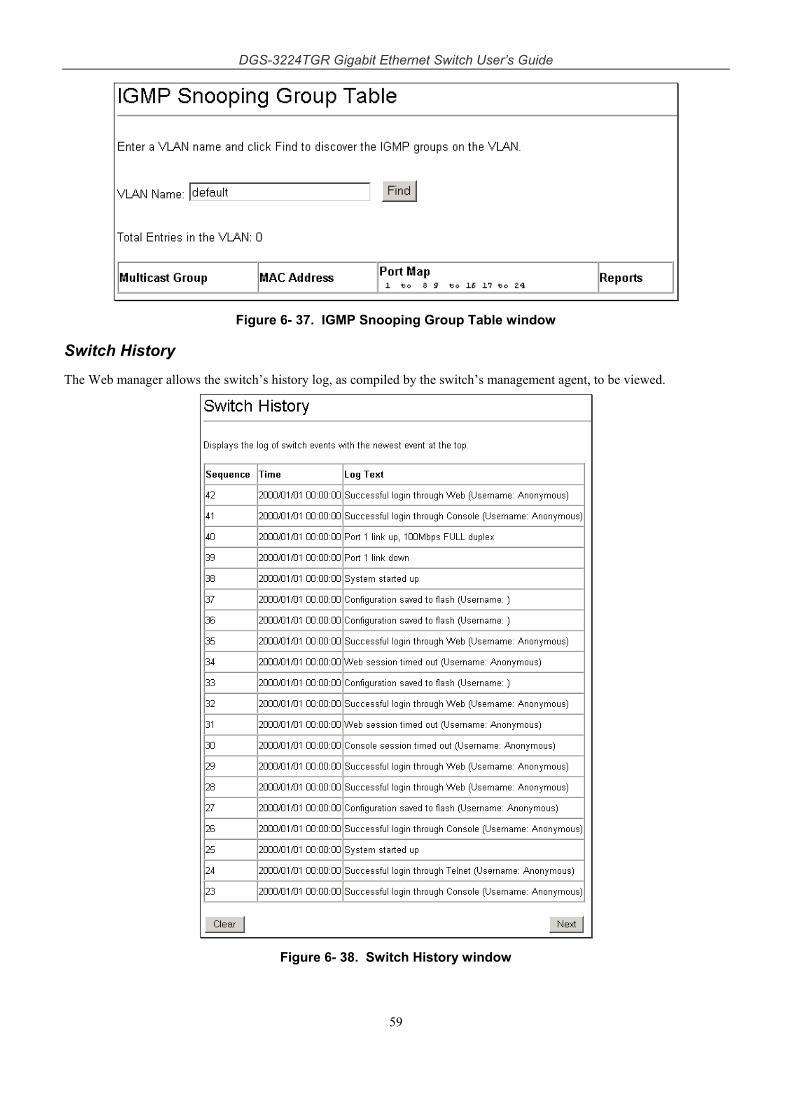
DGS-3224TGR Gigabit Ethernet Switch User’s Guide
59
Figure 6- 37. IGMP Snooping Group Table window
Switch History The Web manager allows the switch’s history log, as compiled by the switch’s management agent, to be viewed.
Figure 6- 38. Switch History window
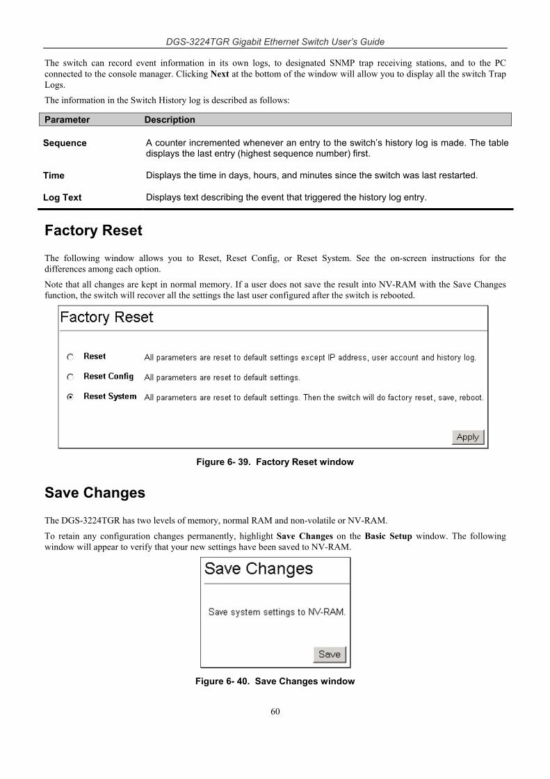
DGS-3224TGR Gigabit Ethernet Switch User’s Guide
60
The switch can record event information in its own logs, to designated SNMP trap receiving stations, and to the PC connected to the console manager. Clicking Next at the bottom of the window will allow you to display all the switch Trap Logs.
The information in the Switch History log is described as follows:
Parameter Description
Sequence A counter incremented whenever an entry to the switch’s history log is made. The table displays the last entry (highest sequence number) first.
Time Displays the time in days, hours, and minutes since the switch was last restarted.
Log Text Displays text describing the event that triggered the history log entry.
Factory Reset
The following window allows you to Reset, Reset Config, or Reset System. See the on-screen instructions for the differences among each option.
Note that all changes are kept in normal memory. If a user does not save the result into NV-RAM with the Save Changes function, the switch will recover all the settings the last user configured after the switch is rebooted.
Figure 6- 39. Factory Reset window
Save Changes
The DGS-3224TGR has two levels of memory, normal RAM and non-volatile or NV-RAM.
To retain any configuration changes permanently, highlight Save Changes on the Basic Setup window. The following window will appear to verify that your new settings have been saved to NV-RAM.
Figure 6- 40. Save Changes window
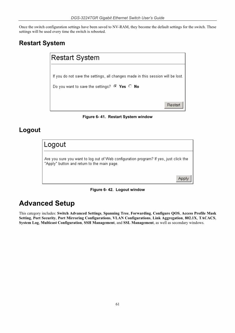
DGS-3224TGR Gigabit Ethernet Switch User’s Guide
61
Once the switch configuration settings have been saved to NV-RAM, they become the default settings for the switch. These settings will be used every time the switch is rebooted.
Restart System
Figure 6- 41. Restart System window
Logout
Figure 6- 42. Logout window
Advanced Setup This category includes: Switch Advanced Settings, Spanning Tree, Forwarding, Configure QOS, Access Profile Mask Setting, Port Security, Port Mirroring Configurations, VLAN Configurations, Link Aggregation, 802.1X, TACACS, System Log, Multicast Configuration, SSH Management, and SSL Management, as well as secondary windows.
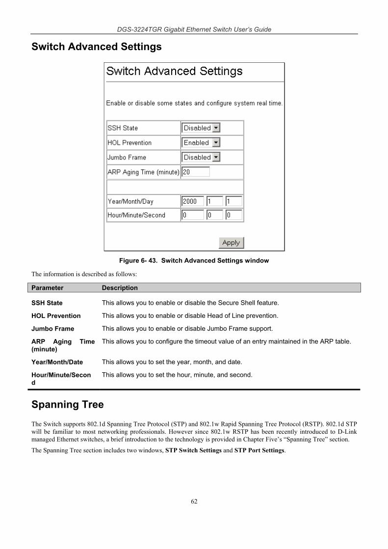
DGS-3224TGR Gigabit Ethernet Switch User’s Guide
62
Switch Advanced Settings
Figure 6- 43. Switch Advanced Settings window
The information is described as follows:
Parameter Description
SSH State This allows you to enable or disable the Secure Shell feature.
HOL Prevention This allows you to enable or disable Head of Line prevention.
Jumbo Frame This allows you to enable or disable Jumbo Frame support.
ARP Aging Time (minute)
This allows you to configure the timeout value of an entry maintained in the ARP table.
Year/Month/Date This allows you to set the year, month, and date.
Hour/Minute/Second
This allows you to set the hour, minute, and second.
Spanning Tree
The Switch supports 802.1d Spanning Tree Protocol (STP) and 802.1w Rapid Spanning Tree Protocol (RSTP). 802.1d STP will be familiar to most networking professionals. However since 802.1w RSTP has been recently introduced to D-Link managed Ethernet switches, a brief introduction to the technology is provided in Chapter Five’s “Spanning Tree” section.
The Spanning Tree section includes two windows, STP Switch Settings and STP Port Settings.
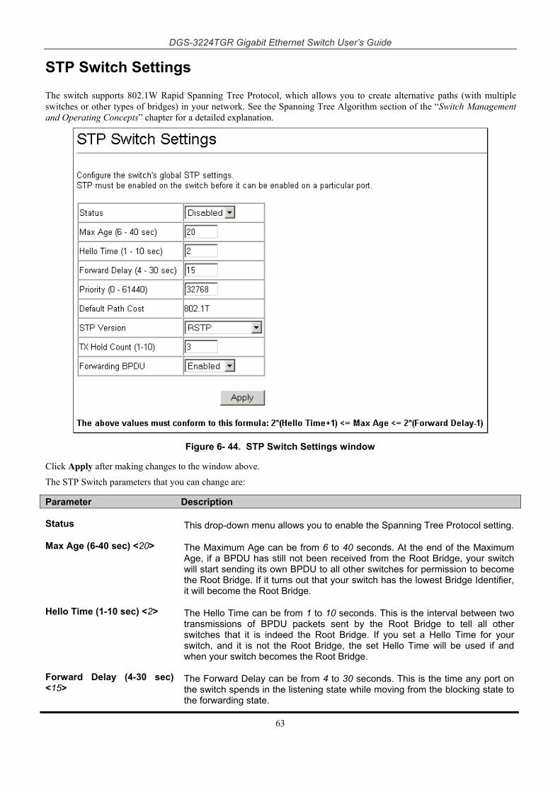
DGS-3224TGR Gigabit Ethernet Switch User’s Guide
63
STP Switch Settings
The switch supports 802.1W Rapid Spanning Tree Protocol, which allows you to create alternative paths (with multiple switches or other types of bridges) in your network. See the Spanning Tree Algorithm section of the “Switch Management and Operating Concepts” chapter for a detailed explanation.
Figure 6- 44. STP Switch Settings window
Click Apply after making changes to the window above.
The STP Switch parameters that you can change are:
Parameter Description
Status This drop-down menu allows you to enable the Spanning Tree Protocol setting.
Max Age (6-40 sec) <20> The Maximum Age can be from 6 to 40 seconds. At the end of the Maximum Age, if a BPDU has still not been received from the Root Bridge, your switch will start sending its own BPDU to all other switches for permission to become the Root Bridge. If it turns out that your switch has the lowest Bridge Identifier, it will become the Root Bridge.
Hello Time (1-10 sec) <2> The Hello Time can be from 1 to 10 seconds. This is the interval between two transmissions of BPDU packets sent by the Root Bridge to tell all other switches that it is indeed the Root Bridge. If you set a Hello Time for your switch, and it is not the Root Bridge, the set Hello Time will be used if and when your switch becomes the Root Bridge.
Forward Delay (4-30 sec) <15>
The Forward Delay can be from 4 to 30 seconds. This is the time any port on the switch spends in the listening state while moving from the blocking state to the forwarding state.
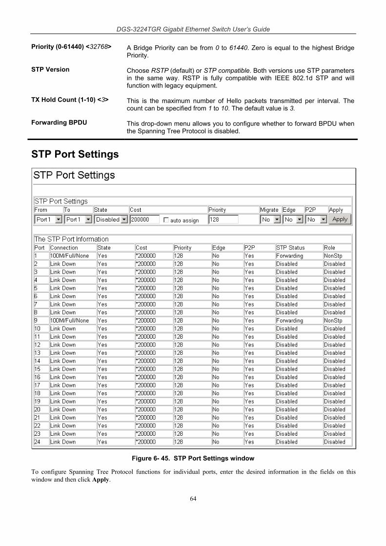
DGS-3224TGR Gigabit Ethernet Switch User’s Guide
64
Priority (0-61440) <32768> A Bridge Priority can be from 0 to 61440. Zero is equal to the highest Bridge Priority.
STP Version Choose RSTP (default) or STP compatible. Both versions use STP parameters in the same way. RSTP is fully compatible with IEEE 802.1d STP and will function with legacy equipment.
TX Hold Count (1-10) <3> This is the maximum number of Hello packets transmitted per interval. The count can be specified from 1 to 10. The default value is 3.
Forwarding BPDU This drop-down menu allows you to configure whether to forward BPDU when the Spanning Tree Protocol is disabled.
STP Port Settings
Figure 6- 45. STP Port Settings window
To configure Spanning Tree Protocol functions for individual ports, enter the desired information in the fields on this window and then click Apply.
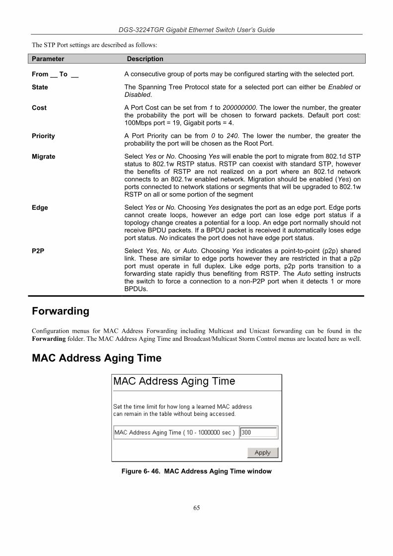
DGS-3224TGR Gigabit Ethernet Switch User’s Guide
65
The STP Port settings are described as follows:
Parameter Description
From __ To __ A consecutive group of ports may be configured starting with the selected port.
State The Spanning Tree Protocol state for a selected port can either be Enabled or Disabled.
Cost A Port Cost can be set from 1 to 200000000. The lower the number, the greater the probability the port will be chosen to forward packets. Default port cost: 100Mbps port = 19, Gigabit ports = 4.
Priority A Port Priority can be from 0 to 240. The lower the number, the greater the probability the port will be chosen as the Root Port.
Migrate Select Yes or No. Choosing Yes will enable the port to migrate from 802.1d STP status to 802.1w RSTP status. RSTP can coexist with standard STP, however the benefits of RSTP are not realized on a port where an 802.1d network connects to an 802.1w enabled network. Migration should be enabled (Yes) on ports connected to network stations or segments that will be upgraded to 802.1w RSTP on all or some portion of the segment
Edge Select Yes or No. Choosing Yes designates the port as an edge port. Edge ports cannot create loops, however an edge port can lose edge port status if a topology change creates a potential for a loop. An edge port normally should not receive BPDU packets. If a BPDU packet is received it automatically loses edge port status. No indicates the port does not have edge port status.
P2P Select Yes, No, or Auto. Choosing Yes indicates a point-to-point (p2p) shared link. These are similar to edge ports however they are restricted in that a p2p port must operate in full duplex. Like edge ports, p2p ports transition to a forwarding state rapidly thus benefiting from RSTP. The Auto setting instructs the switch to force a connection to a non-P2P port when it detects 1 or more BPDUs.
Forwarding
Configuration menus for MAC Address Forwarding including Multicast and Unicast forwarding can be found in the Forwarding folder. The MAC Address Aging Time and Broadcast/Multicast Storm Control menus are located here as well.
MAC Address Aging Time
Figure 6- 46. MAC Address Aging Time window
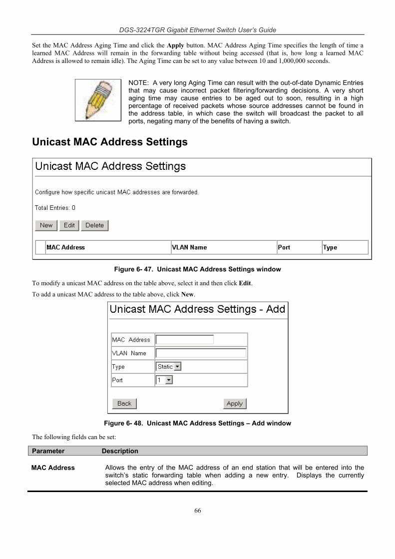
DGS-3224TGR Gigabit Ethernet Switch User’s Guide
66
Set the MAC Address Aging Time and click the Apply button. MAC Address Aging Time specifies the length of time a learned MAC Address will remain in the forwarding table without being accessed (that is, how long a learned MAC Address is allowed to remain idle). The Aging Time can be set to any value between 10 and 1,000,000 seconds.
NOTE: A very long Aging Time can result with the out-of-date Dynamic Entries that may cause incorrect packet filtering/forwarding decisions. A very short aging time may cause entries to be aged out to soon, resulting in a high percentage of received packets whose source addresses cannot be found in the address table, in which case the switch will broadcast the packet to all ports, negating many of the benefits of having a switch.
Unicast MAC Address Settings
Figure 6- 47. Unicast MAC Address Settings window
To modify a unicast MAC address on the table above, select it and then click Edit.
To add a unicast MAC address to the table above, click New.
Figure 6- 48. Unicast MAC Address Settings – Add window
The following fields can be set:
Parameter Description
MAC Address Allows the entry of the MAC address of an end station that will be entered into the switch’s static forwarding table when adding a new entry. Displays the currently selected MAC address when editing.
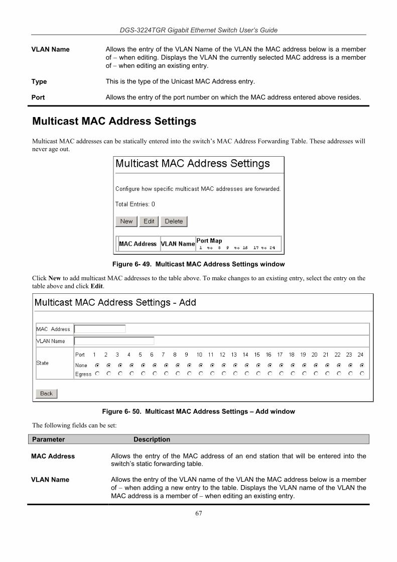
DGS-3224TGR Gigabit Ethernet Switch User’s Guide
67
VLAN Name Allows the entry of the VLAN Name of the VLAN the MAC address below is a member of − when editing. Displays the VLAN the currently selected MAC address is a member of − when editing an existing entry.
Type This is the type of the Unicast MAC Address entry.
Port Allows the entry of the port number on which the MAC address entered above resides.
Multicast MAC Address Settings
Multicast MAC addresses can be statically entered into the switch’s MAC Address Forwarding Table. These addresses will never age out.
Figure 6- 49. Multicast MAC Address Settings window
Click New to add multicast MAC addresses to the table above. To make changes to an existing entry, select the entry on the table above and click Edit.
Figure 6- 50. Multicast MAC Address Settings – Add window
The following fields can be set:
Parameter Description
MAC Address Allows the entry of the MAC address of an end station that will be entered into the switch’s static forwarding table.
VLAN Name Allows the entry of the VLAN name of the VLAN the MAC address below is a member of − when adding a new entry to the table. Displays the VLAN name of the VLAN the MAC address is a member of − when editing an existing entry.
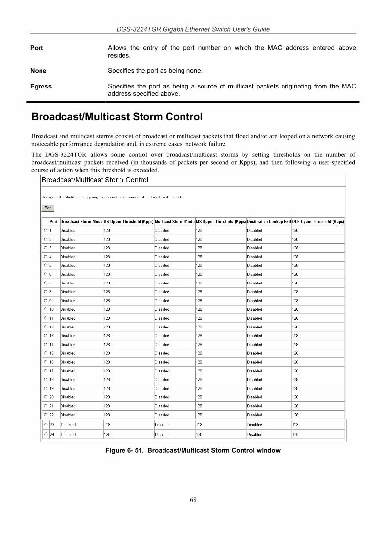
DGS-3224TGR Gigabit Ethernet Switch User’s Guide
68
Port Allows the entry of the port number on which the MAC address entered above resides.
None Specifies the port as being none.
Egress Specifies the port as being a source of multicast packets originating from the MAC address specified above.
Broadcast/Multicast Storm Control
Broadcast and multicast storms consist of broadcast or multicast packets that flood and/or are looped on a network causing noticeable performance degradation and, in extreme cases, network failure.
The DGS-3224TGR allows some control over broadcast/multicast storms by setting thresholds on the number of broadcast/multicast packets received (in thousands of packets per second or Kpps), and then following a user-specified course of action when this threshold is exceeded.
Figure 6- 51. Broadcast/Multicast Storm Control window
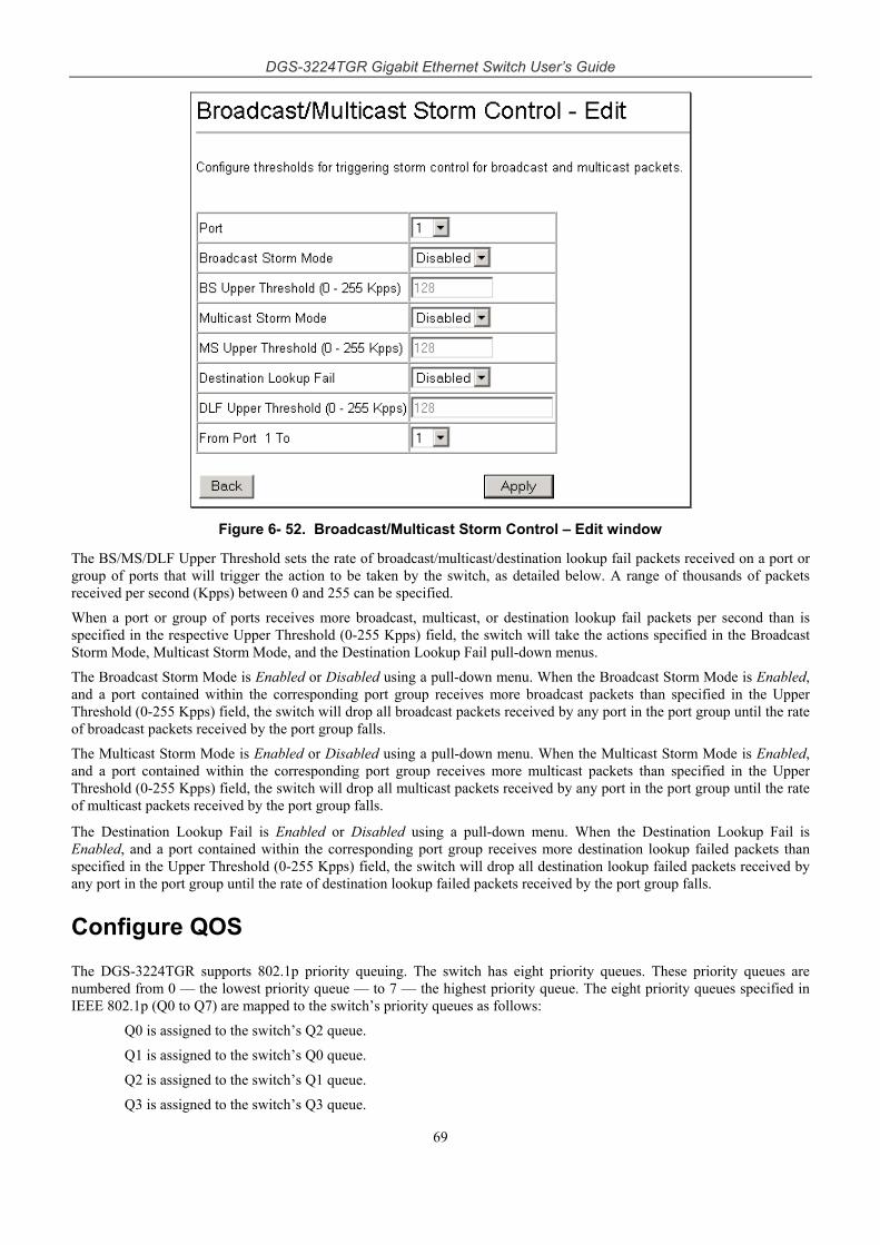
DGS-3224TGR Gigabit Ethernet Switch User’s Guide
69
Figure 6- 52. Broadcast/Multicast Storm Control – Edit window
The BS/MS/DLF Upper Threshold sets the rate of broadcast/multicast/destination lookup fail packets received on a port or group of ports that will trigger the action to be taken by the switch, as detailed below. A range of thousands of packets received per second (Kpps) between 0 and 255 can be specified.
When a port or group of ports receives more broadcast, multicast, or destination lookup fail packets per second than is specified in the respective Upper Threshold (0-255 Kpps) field, the switch will take the actions specified in the Broadcast Storm Mode, Multicast Storm Mode, and the Destination Lookup Fail pull-down menus.
The Broadcast Storm Mode is Enabled or Disabled using a pull-down menu. When the Broadcast Storm Mode is Enabled, and a port contained within the corresponding port group receives more broadcast packets than specified in the Upper Threshold (0-255 Kpps) field, the switch will drop all broadcast packets received by any port in the port group until the rate of broadcast packets received by the port group falls.
The Multicast Storm Mode is Enabled or Disabled using a pull-down menu. When the Multicast Storm Mode is Enabled, and a port contained within the corresponding port group receives more multicast packets than specified in the Upper Threshold (0-255 Kpps) field, the switch will drop all multicast packets received by any port in the port group until the rate of multicast packets received by the port group falls.
The Destination Lookup Fail is Enabled or Disabled using a pull-down menu. When the Destination Lookup Fail is Enabled, and a port contained within the corresponding port group receives more destination lookup failed packets than specified in the Upper Threshold (0-255 Kpps) field, the switch will drop all destination lookup failed packets received by any port in the port group until the rate of destination lookup failed packets received by the port group falls.
Configure QOS
The DGS-3224TGR supports 802.1p priority queuing. The switch has eight priority queues. These priority queues are numbered from 0 — the lowest priority queue — to 7 — the highest priority queue. The eight priority queues specified in IEEE 802.1p (Q0 to Q7) are mapped to the switch’s priority queues as follows:
Q0 is assigned to the switch’s Q2 queue.
Q1 is assigned to the switch’s Q0 queue.
Q2 is assigned to the switch’s Q1 queue.
Q3 is assigned to the switch’s Q3 queue.
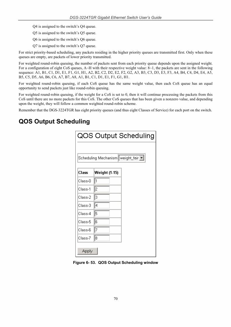
DGS-3224TGR Gigabit Ethernet Switch User’s Guide
70
Q4 is assigned to the switch’s Q4 queue.
Q5 is assigned to the switch’s Q5 queue.
Q6 is assigned to the switch’s Q6 queue.
Q7 is assigned to the switch’s Q7 queue. For strict priority-based scheduling, any packets residing in the higher priority queues are transmitted first. Only when these queues are empty, are packets of lower priority transmitted.
For weighted round-robin queuing, the number of packets sent from each priority queue depends upon the assigned weight. For a configuration of eight CoS queues, A~H with their respective weight value: 8~1, the packets are sent in the following sequence: A1, B1, C1, D1, E1, F1, G1, H1, A2, B2, C2, D2, E2, F2, G2, A3, B3, C3, D3, E3, F3, A4, B4, C4, D4, E4, A5, B5, C5, D5, A6, B6, C6, A7, B7, A8, A1, B1, C1, D1, E1, F1, G1, H1.
For weighted round-robin queuing, if each CoS queue has the same weight value, then each CoS queue has an equal opportunity to send packets just like round-robin queuing.
For weighted round-robin queuing, if the weight for a CoS is set to 0, then it will continue processing the packets from this CoS until there are no more packets for this CoS. The other CoS queues that has been given a nonzero value, and depending upon the weight, they will follow a common weighted round-robin scheme.
Remember that the DGS-3224TGR has eight priority queues (and thus eight Classes of Service) for each port on the switch.
QOS Output Scheduling
Figure 6- 53. QOS Output Scheduling window
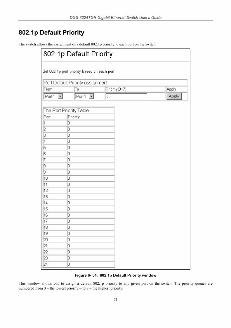
DGS-3224TGR Gigabit Ethernet Switch User’s Guide
71
802.1p Default Priority
The switch allows the assignment of a default 802.1p priority to each port on the switch.
Figure 6- 54. 802.1p Default Priority window
This window allows you to assign a default 802.1p priority to any given port on the switch. The priority queues are numbered from 0 − the lowest priority − to 7 − the highest priority.
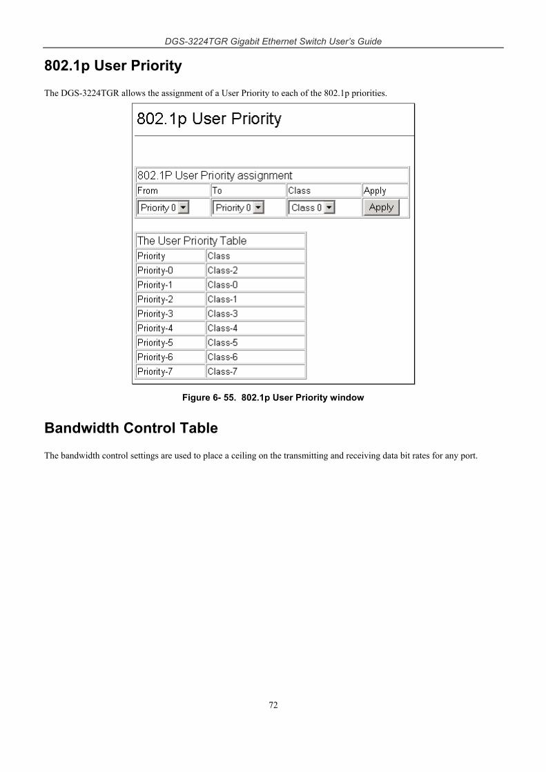
DGS-3224TGR Gigabit Ethernet Switch User’s Guide
72
802.1p User Priority
The DGS-3224TGR allows the assignment of a User Priority to each of the 802.1p priorities.
Figure 6- 55. 802.1p User Priority window
Bandwidth Control Table
The bandwidth control settings are used to place a ceiling on the transmitting and receiving data bit rates for any port.
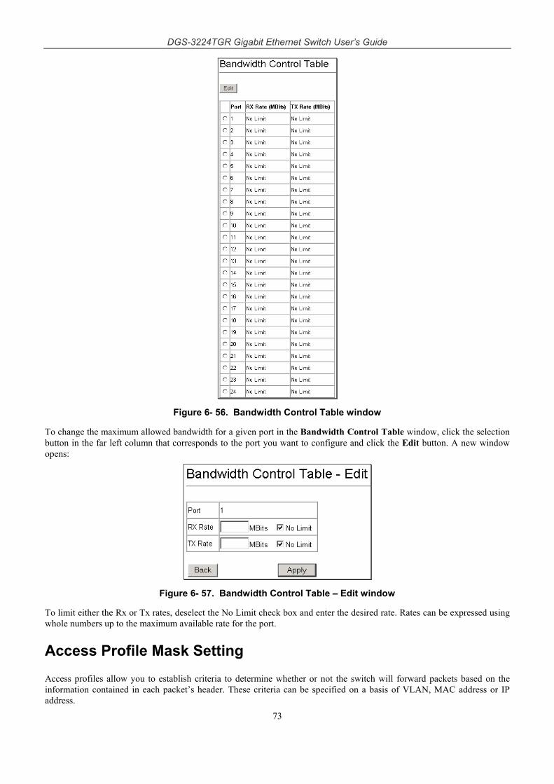
DGS-3224TGR Gigabit Ethernet Switch User’s Guide
73
Figure 6- 56. Bandwidth Control Table window
To change the maximum allowed bandwidth for a given port in the Bandwidth Control Table window, click the selection button in the far left column that corresponds to the port you want to configure and click the Edit button. A new window opens:
Figure 6- 57. Bandwidth Control Table – Edit window
To limit either the Rx or Tx rates, deselect the No Limit check box and enter the desired rate. Rates can be expressed using whole numbers up to the maximum available rate for the port.
Access Profile Mask Setting
Access profiles allow you to establish criteria to determine whether or not the switch will forward packets based on the information contained in each packet’s header. These criteria can be specified on a basis of VLAN, MAC address or IP address.
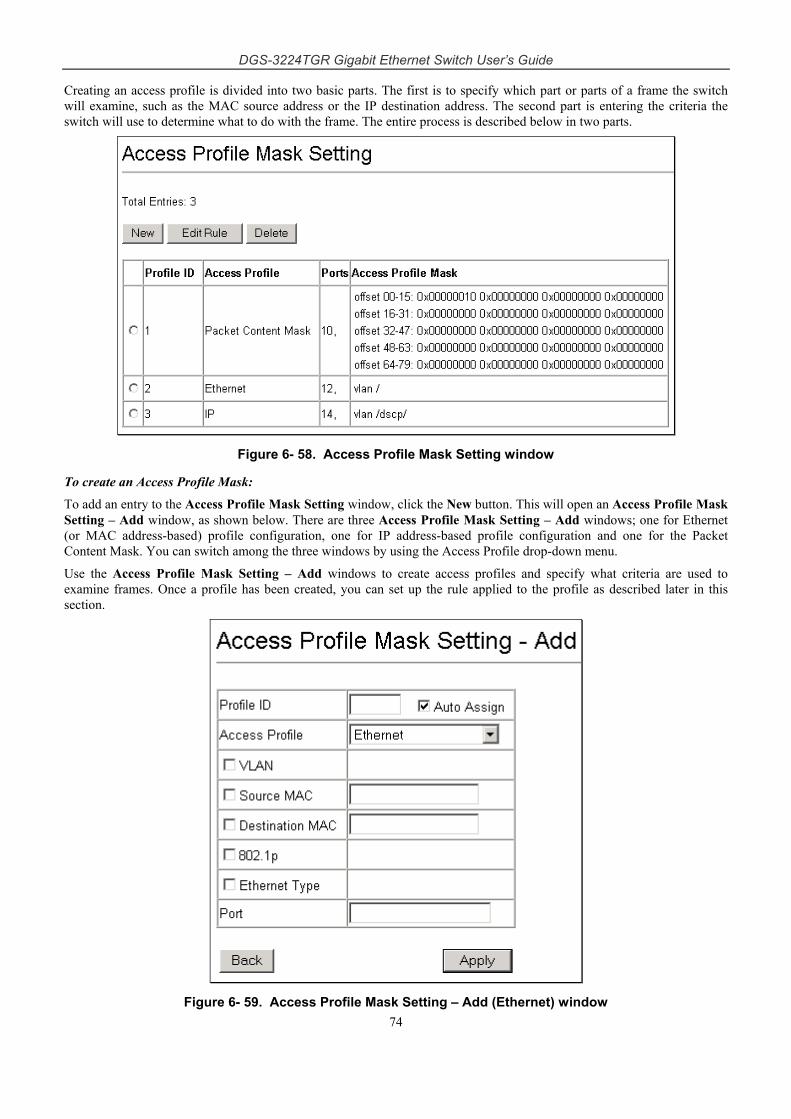
DGS-3224TGR Gigabit Ethernet Switch User’s Guide
74
Creating an access profile is divided into two basic parts. The first is to specify which part or parts of a frame the switch will examine, such as the MAC source address or the IP destination address. The second part is entering the criteria the switch will use to determine what to do with the frame. The entire process is described below in two parts.
Figure 6- 58. Access Profile Mask Setting window
To create an Access Profile Mask:
To add an entry to the Access Profile Mask Setting window, click the New button. This will open an Access Profile Mask Setting – Add window, as shown below. There are three Access Profile Mask Setting – Add windows; one for Ethernet (or MAC address-based) profile configuration, one for IP address-based profile configuration and one for the Packet Content Mask. You can switch among the three windows by using the Access Profile drop-down menu.
Use the Access Profile Mask Setting – Add windows to create access profiles and specify what criteria are used to examine frames. Once a profile has been created, you can set up the rule applied to the profile as described later in this section.
Figure 6- 59. Access Profile Mask Setting – Add (Ethernet) window
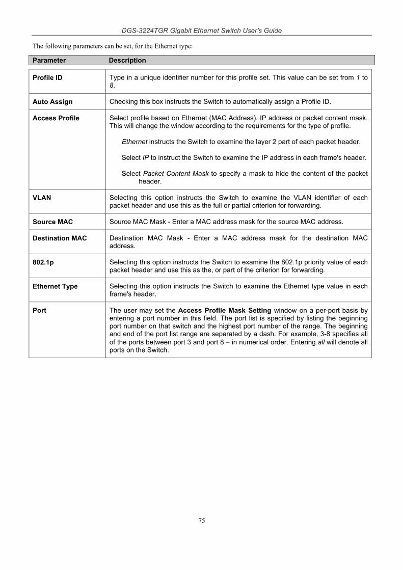
DGS-3224TGR Gigabit Ethernet Switch User’s Guide
75
The following parameters can be set, for the Ethernet type:
Parameter Description
Profile ID Type in a unique identifier number for this profile set. This value can be set from 1 to 8.
Auto Assign Checking this box instructs the Switch to automatically assign a Profile ID.
Access Profile Select profile based on Ethernet (MAC Address), IP address or packet content mask. This will change the window according to the requirements for the type of profile.
Ethernet instructs the Switch to examine the layer 2 part of each packet header.
Select IP to instruct the Switch to examine the IP address in each frame's header.
Select Packet Content Mask to specify a mask to hide the content of the packet header.
VLAN Selecting this option instructs the Switch to examine the VLAN identifier of each packet header and use this as the full or partial criterion for forwarding.
Source MAC Source MAC Mask - Enter a MAC address mask for the source MAC address.
Destination MAC Destination MAC Mask - Enter a MAC address mask for the destination MAC address.
802.1p Selecting this option instructs the Switch to examine the 802.1p priority value of each packet header and use this as the, or part of the criterion for forwarding.
Ethernet Type Selecting this option instructs the Switch to examine the Ethernet type value in each frame's header.
Port The user may set the Access Profile Mask Setting window on a per-port basis by entering a port number in this field. The port list is specified by listing the beginning port number on that switch and the highest port number of the range. The beginning and end of the port list range are separated by a dash. For example, 3-8 specifies all of the ports between port 3 and port 8 − in numerical order. Entering all will denote all ports on the Switch.
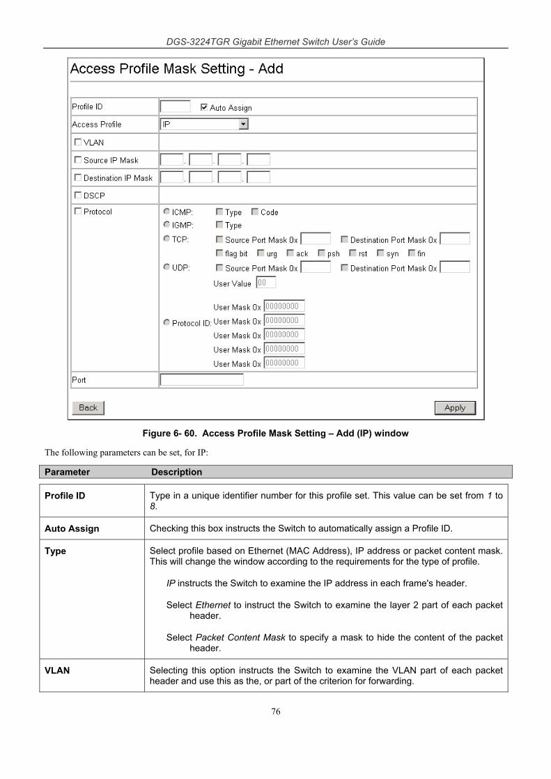
DGS-3224TGR Gigabit Ethernet Switch User’s Guide
76
Figure 6- 60. Access Profile Mask Setting – Add (IP) window
The following parameters can be set, for IP:
Parameter Description
Profile ID Type in a unique identifier number for this profile set. This value can be set from 1 to 8.
Auto Assign Checking this box instructs the Switch to automatically assign a Profile ID.
Type Select profile based on Ethernet (MAC Address), IP address or packet content mask. This will change the window according to the requirements for the type of profile.
IP instructs the Switch to examine the IP address in each frame's header.
Select Ethernet to instruct the Switch to examine the layer 2 part of each packet header.
Select Packet Content Mask to specify a mask to hide the content of the packet header.
VLAN Selecting this option instructs the Switch to examine the VLAN part of each packet header and use this as the, or part of the criterion for forwarding.
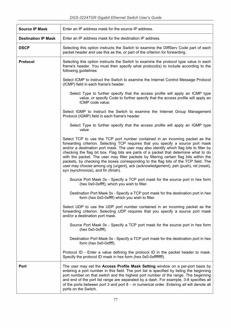
DGS-3224TGR Gigabit Ethernet Switch User’s Guide
77
Source IP Mask Enter an IP address mask for the source IP address.
Destination IP Mask Enter an IP address mask for the destination IP address.
DSCP Selecting this option instructs the Switch to examine the DiffServ Code part of each packet header and use this as the, or part of the criterion for forwarding.
Protocol Selecting this option instructs the Switch to examine the protocol type value in each frame's header. You must then specify what protocol(s) to include according to the following guidelines:
Select ICMP to instruct the Switch to examine the Internet Control Message Protocol (ICMP) field in each frame's header.
Select Type to further specify that the access profile will apply an ICMP type value, or specify Code to further specify that the access profile will apply an ICMP code value.
Select IGMP to instruct the Switch to examine the Internet Group Management Protocol (IGMP) field in each frame's header.
Select Type to further specify that the access profile will apply an IGMP type value
Select TCP to use the TCP port number contained in an incoming packet as the forwarding criterion. Selecting TCP requires that you specify a source port mask and/or a destination port mask. The user may also identify which flag bits to filter by checking the flag bit box. Flag bits are parts of a packet that determine what to do with the packet. The user may filter packets by filtering certain flag bits within the packets, by checking the boxes corresponding to the flag bits of the TCP field. The user may choose among urg (urgent), ack (acknowledgement), psh (push), rst (reset), syn (synchronize), and fin (finish).
Source Port Mask 0x - Specify a TCP port mask for the source port in hex form (hex 0x0-0xffff), which you wish to filter.
Destination Port Mask 0x - Specify a TCP port mask for the destination port in hex form (hex 0x0-0xffff) which you wish to filter.
Select UDP to use the UDP port number contained in an incoming packet as the forwarding criterion. Selecting UDP requires that you specify a source port mask and/or a destination port mask.
Source Port Mask 0x - Specify a TCP port mask for the source port in hex form (hex 0x0-0xffff).
Destination Port Mask 0x - Specify a TCP port mask for the destination port in hex form (hex 0x0-0xffff).
Protocol ID - Enter a value defining the protocol ID in the packet header to mask. Specify the protocol ID mask in hex form (hex 0x0-0xffffffff).
Port The user may set the Access Profile Mask Setting window on a per-port basis by entering a port number in this field. The port list is specified by listing the beginning port number on that switch and the highest port number of the range. The beginning and end of the port list range are separated by a dash. For example, 3-8 specifies all of the ports between port 3 and port 8 − in numerical order. Entering all will denote all ports on the Switch.
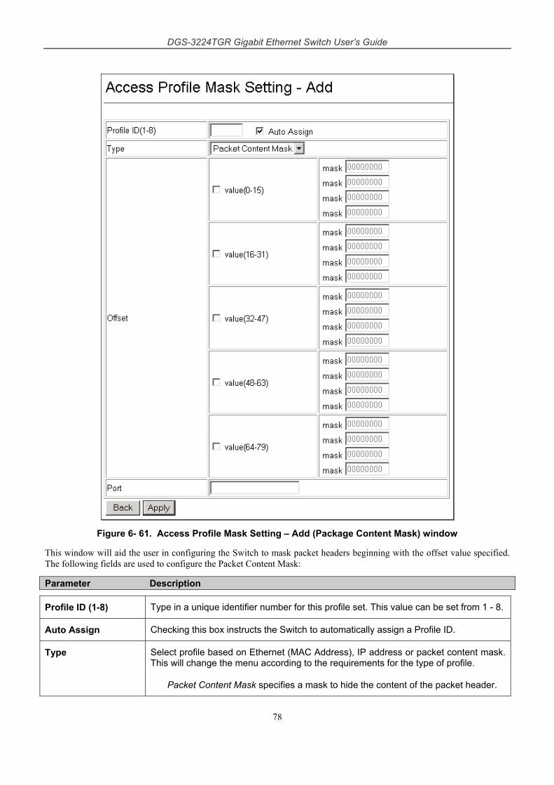
DGS-3224TGR Gigabit Ethernet Switch User’s Guide
78
Figure 6- 61. Access Profile Mask Setting – Add (Package Content Mask) window
This window will aid the user in configuring the Switch to mask packet headers beginning with the offset value specified. The following fields are used to configure the Packet Content Mask:
Parameter Description
Profile ID (1-8) Type in a unique identifier number for this profile set. This value can be set from 1 - 8.
Auto Assign Checking this box instructs the Switch to automatically assign a Profile ID.
Type Select profile based on Ethernet (MAC Address), IP address or packet content mask. This will change the menu according to the requirements for the type of profile.
Packet Content Mask specifies a mask to hide the content of the packet header.
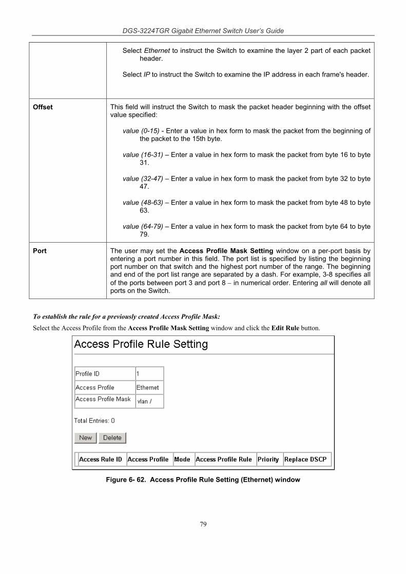
DGS-3224TGR Gigabit Ethernet Switch User’s Guide
79
Select Ethernet to instruct the Switch to examine the layer 2 part of each packet header.
Select IP to instruct the Switch to examine the IP address in each frame's header.
Offset This field will instruct the Switch to mask the packet header beginning with the offset value specified:
value (0-15) - Enter a value in hex form to mask the packet from the beginning of the packet to the 15th byte.
value (16-31) – Enter a value in hex form to mask the packet from byte 16 to byte 31.
value (32-47) – Enter a value in hex form to mask the packet from byte 32 to byte 47.
value (48-63) – Enter a value in hex form to mask the packet from byte 48 to byte 63.
value (64-79) – Enter a value in hex form to mask the packet from byte 64 to byte 79.
Port The user may set the Access Profile Mask Setting window on a per-port basis by entering a port number in this field. The port list is specified by listing the beginning port number on that switch and the highest port number of the range. The beginning and end of the port list range are separated by a dash. For example, 3-8 specifies all of the ports between port 3 and port 8 − in numerical order. Entering all will denote all ports on the Switch.
To establish the rule for a previously created Access Profile Mask:
Select the Access Profile from the Access Profile Mask Setting window and click the Edit Rule button.
Figure 6- 62. Access Profile Rule Setting (Ethernet) window
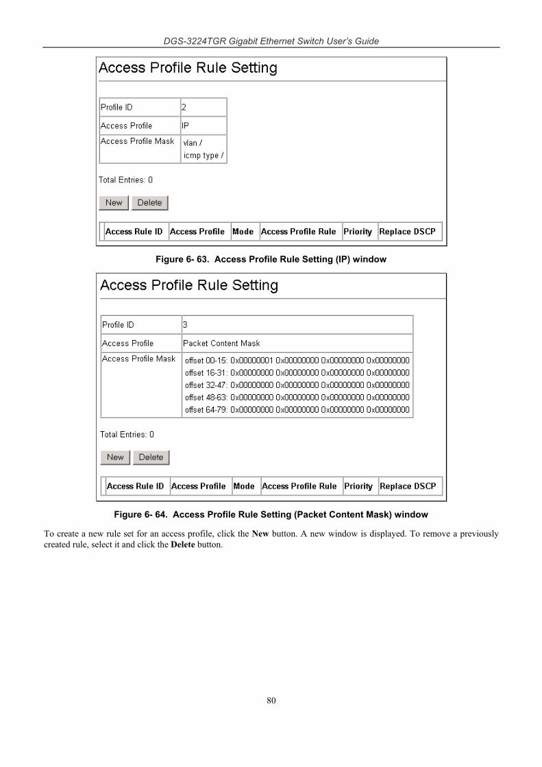
DGS-3224TGR Gigabit Ethernet Switch User’s Guide
80
Figure 6- 63. Access Profile Rule Setting (IP) window
Figure 6- 64. Access Profile Rule Setting (Packet Content Mask) window
To create a new rule set for an access profile, click the New button. A new window is displayed. To remove a previously created rule, select it and click the Delete button.
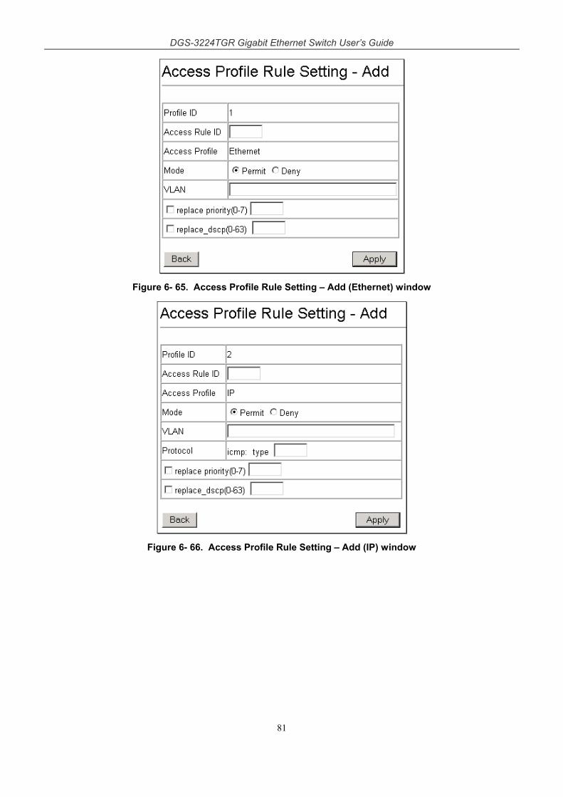
DGS-3224TGR Gigabit Ethernet Switch User’s Guide
81
Figure 6- 65. Access Profile Rule Setting – Add (Ethernet) window
Figure 6- 66. Access Profile Rule Setting – Add (IP) window
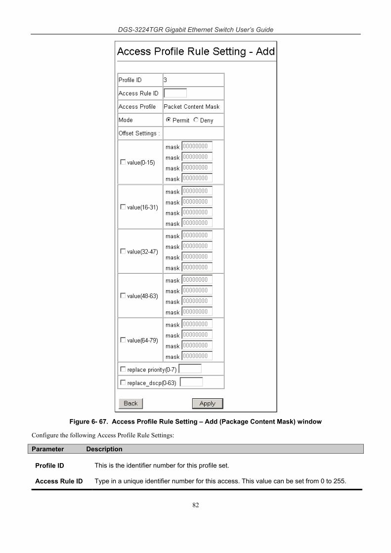
DGS-3224TGR Gigabit Ethernet Switch User’s Guide
82
Figure 6- 67. Access Profile Rule Setting – Add (Package Content Mask) window
Configure the following Access Profile Rule Settings:
Parameter Description
Profile ID This is the identifier number for this profile set.
Access Rule ID Type in a unique identifier number for this access. This value can be set from 0 to 255.
DGS-3224TGR Gigabit Ethernet Switch User’s Guide
83
Access Profile Selected profile based on Ethernet (MAC Address), IP address, or Packet Content Mask.
Ethernet instructs the Switch to examine the layer 2 part of each packet header.
IP instructs the Switch to examine the IP address in each frame's header.
Packet Content Mask instructs the Switch to examine the packet header
Mode Select Permit to specify that the packets that match the access profile are forwarded by the Switch, according to any additional rule added (see below).
Select Deny to specify that packets that do not match the access profile are not forwarded by the Switch and will be filtered.
VLAN Selecting this option instructs the Switch to examine the VLAN part of each packet header and use this as the, or part of the criterion for forwarding.
replace priority (0-7)
Select this option to instruct the switch to replace the 802.1p value (in a packet that meets the selected criteria). In this way, packets meeting the criteria can have their priority handling modified for use within the switch, and then have a different priority value assigned when they leave the switch.
replace_dscp (0-63)
Select this option to instruct the switch to replace the DSCP value (in a packet that meets the selected criteria) with the value entered in the adjacent field.
Protocol Selecting this option instructs the Switch to examine the protocol type value in each frame's header. You must then specify what protocol(s) to include according to the following guidelines:
Select ICMP to instruct the Switch to examine the Internet Control Message Protocol (ICMP) field in each frame's header.
Offset Settings:
This field will instruct the Switch to mask the packet header beginning with the offset value specified:
value (0-15) - Enter a value in hex form to mask the packet from the beginning of the packet to the 15th byte.
value (16-31) - Enter a value in hex form to mask the packet from byte 16 to byte 31.
value (32-47) - Enter a value in hex form to mask the packet from byte 32 to byte 47.
value (48-63) - Enter a value in hex form to mask the packet from byte 48 to byte 63.
value (64-79) - Enter a value in hex form to mask the packet from byte 64 to byte 79.
Port Security
A given port’s (or a range of port’s) dynamic MAC address learning can be locked such that the current source MAC addresses entered into the MAC address forwarding table can not be changed once the port lock is enabled. The port can be locked by changing the Admin State pull-down menu to Enabled on the Port Security Settings – Edit window, shown below, and clicking Apply.
This is a security feature that prevents unauthorized computers (with source MAC addresses unknown to the switch prior to locking the port (or ports) from connecting to the switch’s locked ports and gaining access to the network.
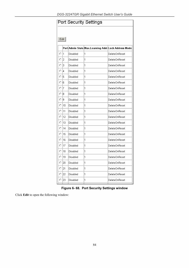
DGS-3224TGR Gigabit Ethernet Switch User’s Guide
84
Figure 6- 68. Port Security Settings window
Click Edit to open the following window:
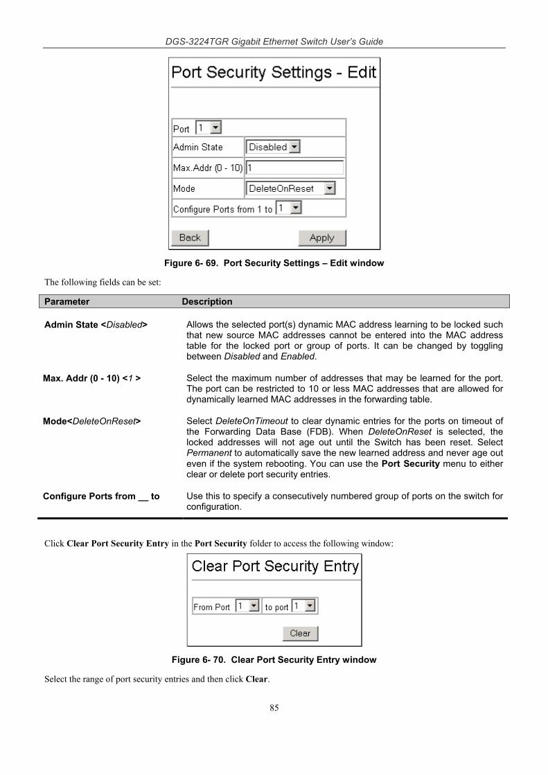
DGS-3224TGR Gigabit Ethernet Switch User’s Guide
85
Figure 6- 69. Port Security Settings – Edit window
The following fields can be set:
Parameter Description
Admin State <Disabled> Allows the selected port(s) dynamic MAC address learning to be locked such that new source MAC addresses cannot be entered into the MAC address table for the locked port or group of ports. It can be changed by toggling between Disabled and Enabled.
Max. Addr (0 - 10) <1 > Select the maximum number of addresses that may be learned for the port. The port can be restricted to 10 or less MAC addresses that are allowed for dynamically learned MAC addresses in the forwarding table.
Mode<DeleteOnReset> Select DeleteOnTimeout to clear dynamic entries for the ports on timeout of the Forwarding Data Base (FDB). When DeleteOnReset is selected, the locked addresses will not age out until the Switch has been reset. Select Permanent to automatically save the new learned address and never age out even if the system rebooting. You can use the Port Security menu to either clear or delete port security entries.
Configure Ports from __ to Use this to specify a consecutively numbered group of ports on the switch for configuration.
Click Clear Port Security Entry in the Port Security folder to access the following window:
Figure 6- 70. Clear Port Security Entry window
Select the range of port security entries and then click Clear.
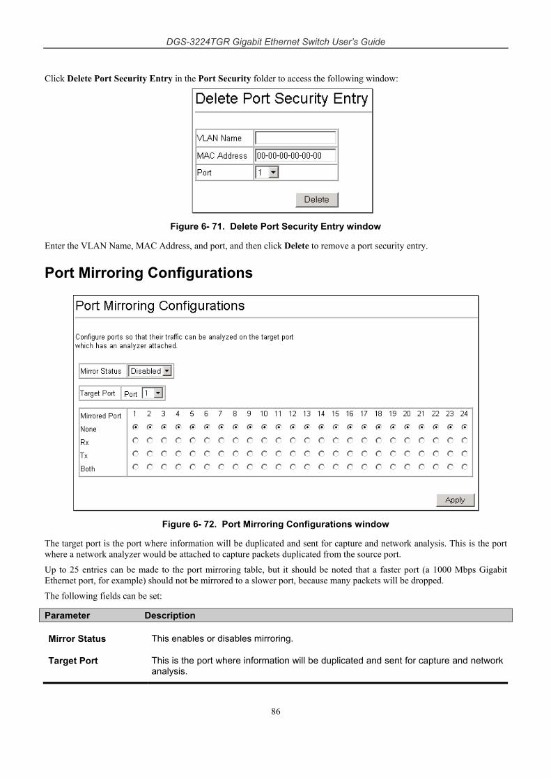
DGS-3224TGR Gigabit Ethernet Switch User’s Guide
86
Click Delete Port Security Entry in the Port Security folder to access the following window:
Figure 6- 71. Delete Port Security Entry window
Enter the VLAN Name, MAC Address, and port, and then click Delete to remove a port security entry.
Port Mirroring Configurations
Figure 6- 72. Port Mirroring Configurations window
The target port is the port where information will be duplicated and sent for capture and network analysis. This is the port where a network analyzer would be attached to capture packets duplicated from the source port.
Up to 25 entries can be made to the port mirroring table, but it should be noted that a faster port (a 1000 Mbps Gigabit Ethernet port, for example) should not be mirrored to a slower port, because many packets will be dropped.
The following fields can be set:
Parameter Description
Mirror Status This enables or disables mirroring.
Target Port This is the port where information will be duplicated and sent for capture and network analysis.
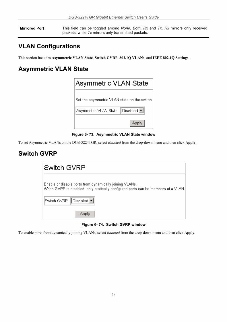
DGS-3224TGR Gigabit Ethernet Switch User’s Guide
87
Mirrored Port This field can be toggled among None, Both, Rx and Tx. Rx mirrors only received packets, while Tx mirrors only transmitted packets.
VLAN Configurations
This section includes Asymmetric VLAN State, Switch GVRP, 802.1Q VLANs, and IEEE 802.1Q Settings.
Asymmetric VLAN State
Figure 6- 73. Asymmetric VLAN State window
To set Asymmetric VLANs on the DGS-3224TGR, select Enabled from the drop-down menu and then click Apply.
Switch GVRP
Figure 6- 74. Switch GVRP window
To enable ports from dynamically joining VLANs, select Enabled from the drop-down menu and then click Apply.
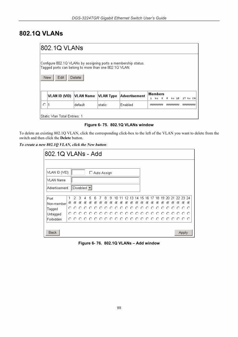
DGS-3224TGR Gigabit Ethernet Switch User’s Guide
88
802.1Q VLANs
Figure 6- 75. 802.1Q VLANs window
To delete an existing 802.1Q VLAN, click the corresponding click-box to the left of the VLAN you want to delete from the switch and then click the Delete button.
To create a new 802.1Q VLAN, click the New button:
Figure 6- 76. 802.1Q VLANs – Add window
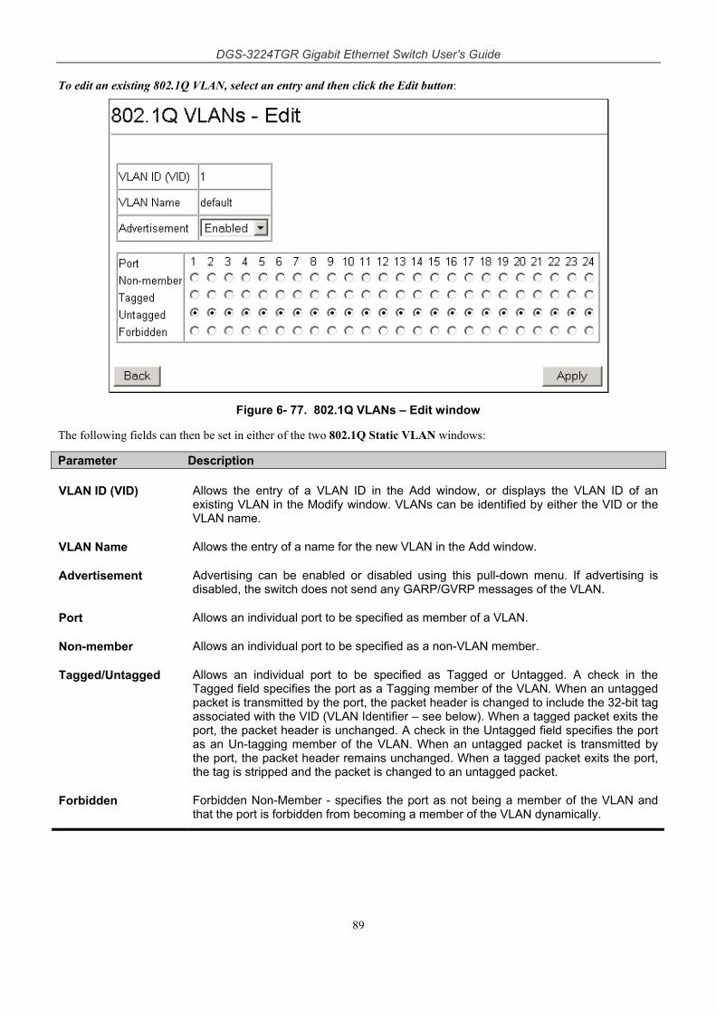
DGS-3224TGR Gigabit Ethernet Switch User’s Guide
89
To edit an existing 802.1Q VLAN, select an entry and then click the Edit button:
Figure 6- 77. 802.1Q VLANs – Edit window
The following fields can then be set in either of the two 802.1Q Static VLAN windows:
Parameter Description
VLAN ID (VID) Allows the entry of a VLAN ID in the Add window, or displays the VLAN ID of an existing VLAN in the Modify window. VLANs can be identified by either the VID or the VLAN name.
VLAN Name Allows the entry of a name for the new VLAN in the Add window.
Advertisement Advertising can be enabled or disabled using this pull-down menu. If advertising is disabled, the switch does not send any GARP/GVRP messages of the VLAN.
Port Allows an individual port to be specified as member of a VLAN.
Non-member Allows an individual port to be specified as a non-VLAN member.
Tagged/Untagged Allows an individual port to be specified as Tagged or Untagged. A check in the Tagged field specifies the port as a Tagging member of the VLAN. When an untagged packet is transmitted by the port, the packet header is changed to include the 32-bit tag associated with the VID (VLAN Identifier – see below). When a tagged packet exits the port, the packet header is unchanged. A check in the Untagged field specifies the port as an Un-tagging member of the VLAN. When an untagged packet is transmitted by the port, the packet header remains unchanged. When a tagged packet exits the port, the tag is stripped and the packet is changed to an untagged packet.
Forbidden Forbidden Non-Member - specifies the port as not being a member of the VLAN and that the port is forbidden from becoming a member of the VLAN dynamically.
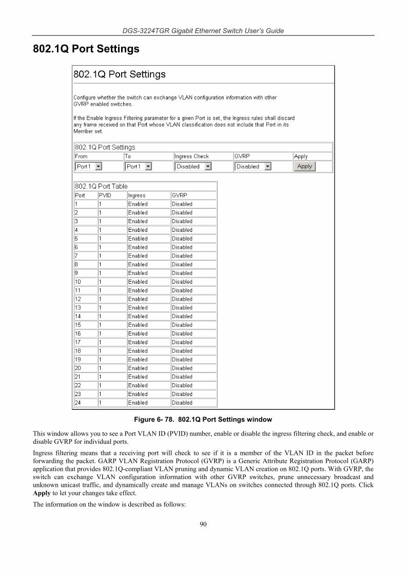
DGS-3224TGR Gigabit Ethernet Switch User’s Guide
90
802.1Q Port Settings
Figure 6- 78. 802.1Q Port Settings window
This window allows you to see a Port VLAN ID (PVID) number, enable or disable the ingress filtering check, and enable or disable GVRP for individual ports.
Ingress filtering means that a receiving port will check to see if it is a member of the VLAN ID in the packet before forwarding the packet. GARP VLAN Registration Protocol (GVRP) is a Generic Attribute Registration Protocol (GARP) application that provides 802.1Q-compliant VLAN pruning and dynamic VLAN creation on 802.1Q ports. With GVRP, the switch can exchange VLAN configuration information with other GVRP switches, prune unnecessary broadcast and unknown unicast traffic, and dynamically create and manage VLANs on switches connected through 802.1Q ports. Click Apply to let your changes take effect.
The information on the window is described as follows:
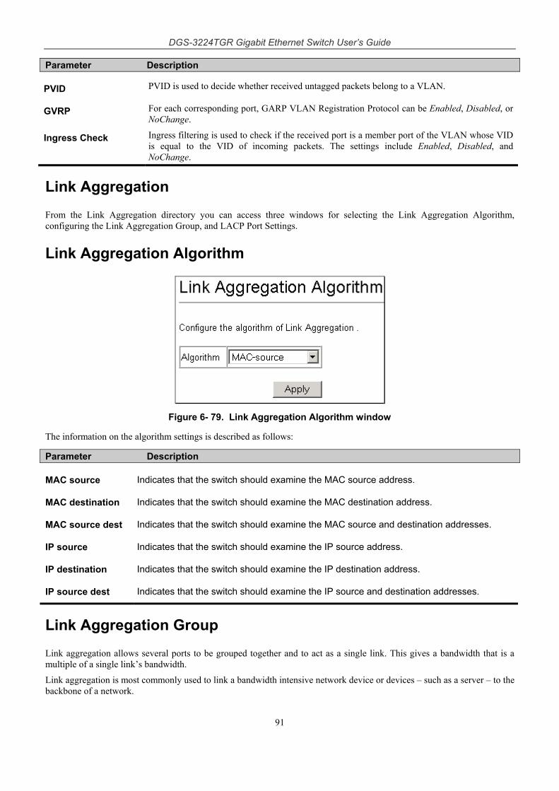
DGS-3224TGR Gigabit Ethernet Switch User’s Guide
91
Parameter Description
PVID PVID is used to decide whether received untagged packets belong to a VLAN.
GVRP For each corresponding port, GARP VLAN Registration Protocol can be Enabled, Disabled, or NoChange.
Ingress Check Ingress filtering is used to check if the received port is a member port of the VLAN whose VID is equal to the VID of incoming packets. The settings include Enabled, Disabled, and NoChange.
Link Aggregation
From the Link Aggregation directory you can access three windows for selecting the Link Aggregation Algorithm, configuring the Link Aggregation Group, and LACP Port Settings.
Link Aggregation Algorithm
Figure 6- 79. Link Aggregation Algorithm window
The information on the algorithm settings is described as follows:
Parameter Description
MAC source Indicates that the switch should examine the MAC source address.
MAC destination Indicates that the switch should examine the MAC destination address.
MAC source dest Indicates that the switch should examine the MAC source and destination addresses.
IP source Indicates that the switch should examine the IP source address.
IP destination Indicates that the switch should examine the IP destination address.
IP source dest Indicates that the switch should examine the IP source and destination addresses.
Link Aggregation Group
Link aggregation allows several ports to be grouped together and to act as a single link. This gives a bandwidth that is a multiple of a single link’s bandwidth.
Link aggregation is most commonly used to link a bandwidth intensive network device or devices – such as a server – to the backbone of a network.
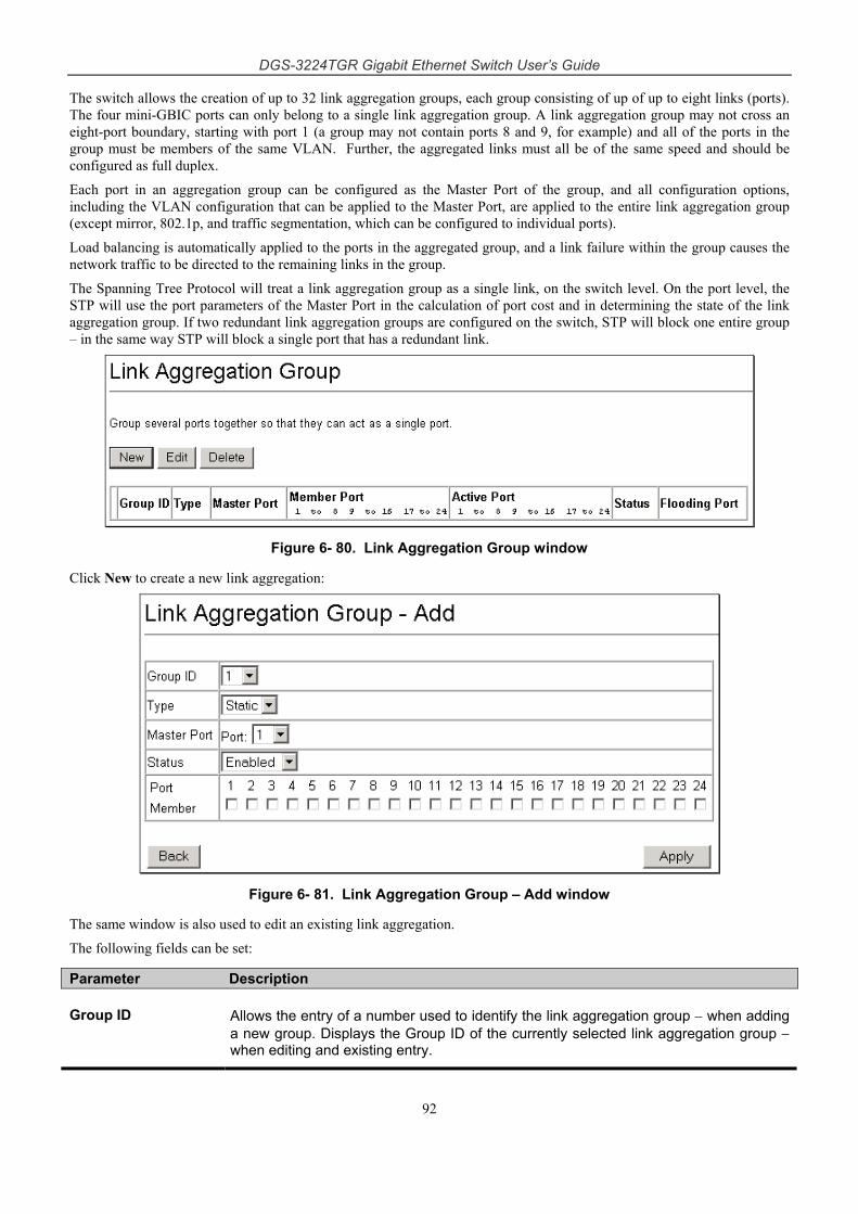
DGS-3224TGR Gigabit Ethernet Switch User’s Guide
92
The switch allows the creation of up to 32 link aggregation groups, each group consisting of up of up to eight links (ports). The four mini-GBIC ports can only belong to a single link aggregation group. A link aggregation group may not cross an eight-port boundary, starting with port 1 (a group may not contain ports 8 and 9, for example) and all of the ports in the group must be members of the same VLAN. Further, the aggregated links must all be of the same speed and should be configured as full duplex.
Each port in an aggregation group can be configured as the Master Port of the group, and all configuration options, including the VLAN configuration that can be applied to the Master Port, are applied to the entire link aggregation group (except mirror, 802.1p, and traffic segmentation, which can be configured to individual ports).
Load balancing is automatically applied to the ports in the aggregated group, and a link failure within the group causes the network traffic to be directed to the remaining links in the group.
The Spanning Tree Protocol will treat a link aggregation group as a single link, on the switch level. On the port level, the STP will use the port parameters of the Master Port in the calculation of port cost and in determining the state of the link aggregation group. If two redundant link aggregation groups are configured on the switch, STP will block one entire group – in the same way STP will block a single port that has a redundant link.
Figure 6- 80. Link Aggregation Group window
Click New to create a new link aggregation:
Figure 6- 81. Link Aggregation Group – Add window
The same window is also used to edit an existing link aggregation.
The following fields can be set:
Parameter Description
Group ID Allows the entry of a number used to identify the link aggregation group − when adding a new group. Displays the Group ID of the currently selected link aggregation group − when editing and existing entry.
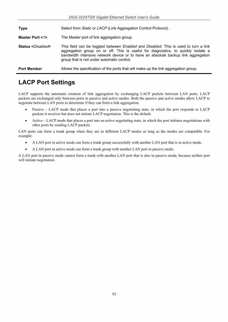
DGS-3224TGR Gigabit Ethernet Switch User’s Guide
93
Type Select from Static or LACP (Link Aggregation Control Protocol).
Master Port <1> The Master port of link aggregation group.
Status <Disabled> This field can be toggled between Enabled and Disabled. This is used to turn a link aggregation group on or off. This is useful for diagnostics, to quickly isolate a bandwidth intensive network device or to have an absolute backup link aggregation group that is not under automatic control.
Port Member Allows the specification of the ports that will make up the link aggregation group.
LACP Port Settings
LACP supports the automatic creation of link aggregation by exchanging LACP packets between LAN ports. LACP packets are exchanged only between ports in passive and active modes. Both the passive and active modes allow LACP to negotiate between LAN ports to determine if they can form a link aggregation.
• Passive – LACP mode that places a port into a passive negotiating state, in which the port responds to LACP packets it receives but does not initiate LACP negotiation. This is the default.
• Active – LACP mode that places a port into an active negotiating state, in which the port initiates negotiations with other ports by sending LACP packets.
LAN ports can form a trunk group when they are in different LACP modes as long as the modes are compatible. For example:
• A LAN port in active mode can form a trunk group successfully with another LAN port that is in active mode.
• A LAN port in active mode can form a trunk group with another LAN port in passive mode.
A LAN port in passive mode cannot form a trunk with another LAN port that is also in passive mode, because neither port will initiate negotiation.
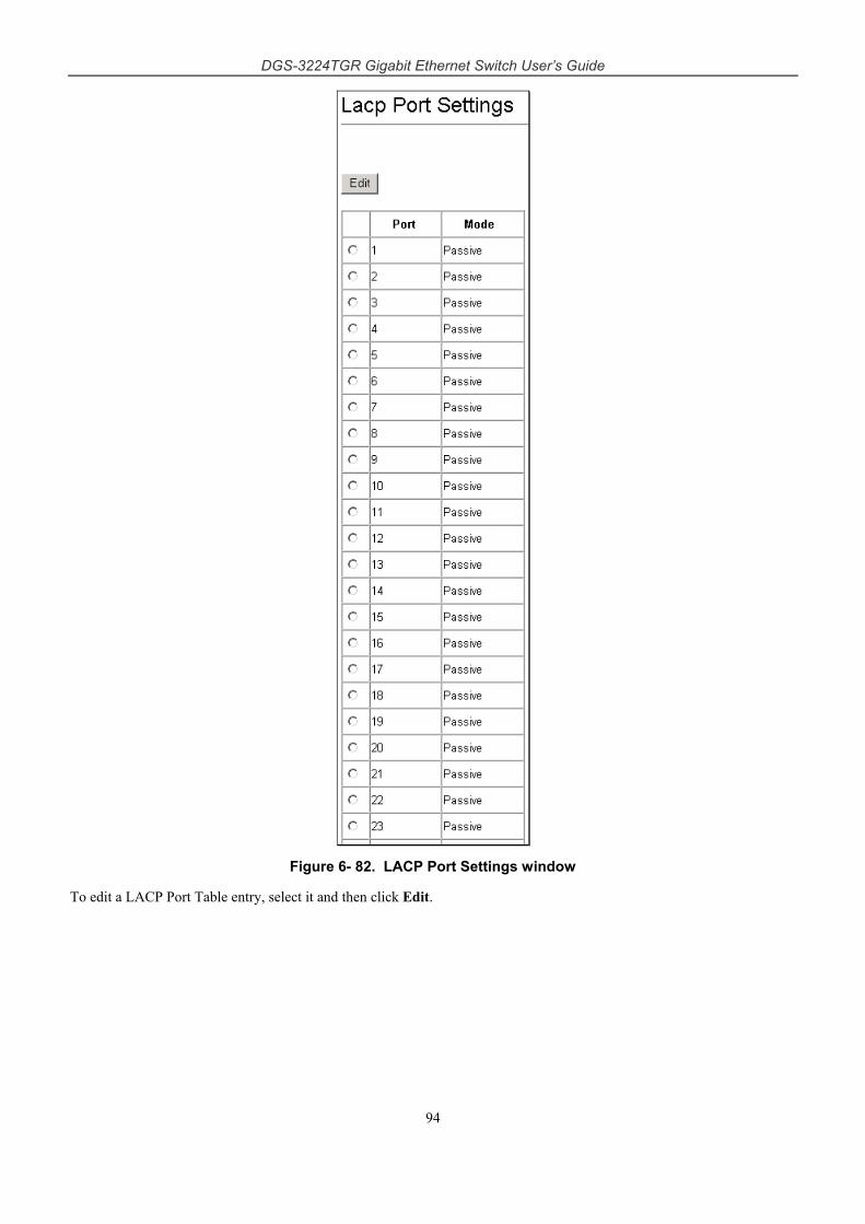
DGS-3224TGR Gigabit Ethernet Switch User’s Guide
94
Figure 6- 82. LACP Port Settings window
To edit a LACP Port Table entry, select it and then click Edit.
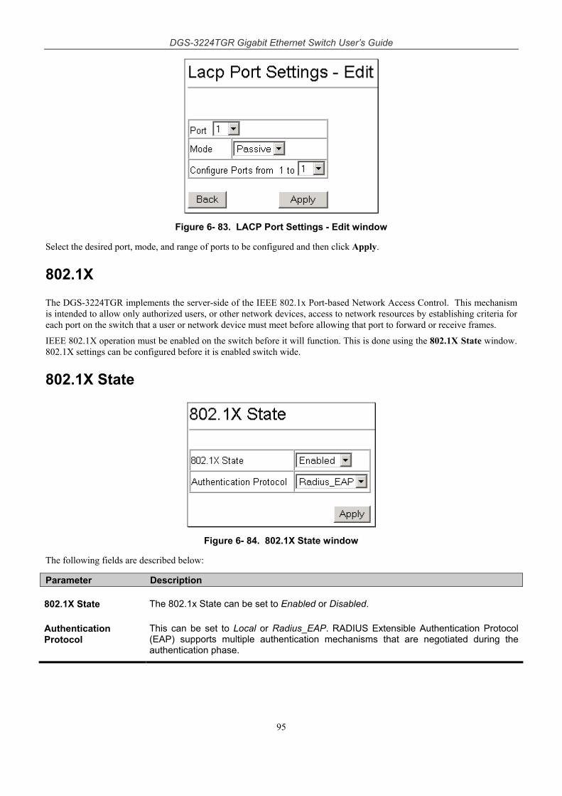
DGS-3224TGR Gigabit Ethernet Switch User’s Guide
95
Figure 6- 83. LACP Port Settings - Edit window
Select the desired port, mode, and range of ports to be configured and then click Apply.
802.1X
The DGS-3224TGR implements the server-side of the IEEE 802.1x Port-based Network Access Control. This mechanism is intended to allow only authorized users, or other network devices, access to network resources by establishing criteria for each port on the switch that a user or network device must meet before allowing that port to forward or receive frames.
IEEE 802.1X operation must be enabled on the switch before it will function. This is done using the 802.1X State window. 802.1X settings can be configured before it is enabled switch wide.
802.1X State
Figure 6- 84. 802.1X State window
The following fields are described below:
Parameter Description
802.1X State The 802.1x State can be set to Enabled or Disabled.
Authentication Protocol
This can be set to Local or Radius_EAP. RADIUS Extensible Authentication Protocol (EAP) supports multiple authentication mechanisms that are negotiated during the authentication phase.
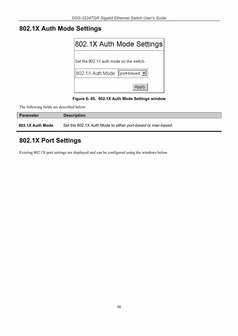
DGS-3224TGR Gigabit Ethernet Switch User’s Guide
96
802.1X Auth Mode Settings
Figure 6- 85. 802.1X Auth Mode Settings window
The following fields are described below:
Parameter Description
802.1X Auth Mode Set the 802.1X Auth Mode to either port-based or mac-based.
802.1X Port Settings
Existing 802.1X port settings are displayed and can be configured using the windows below.
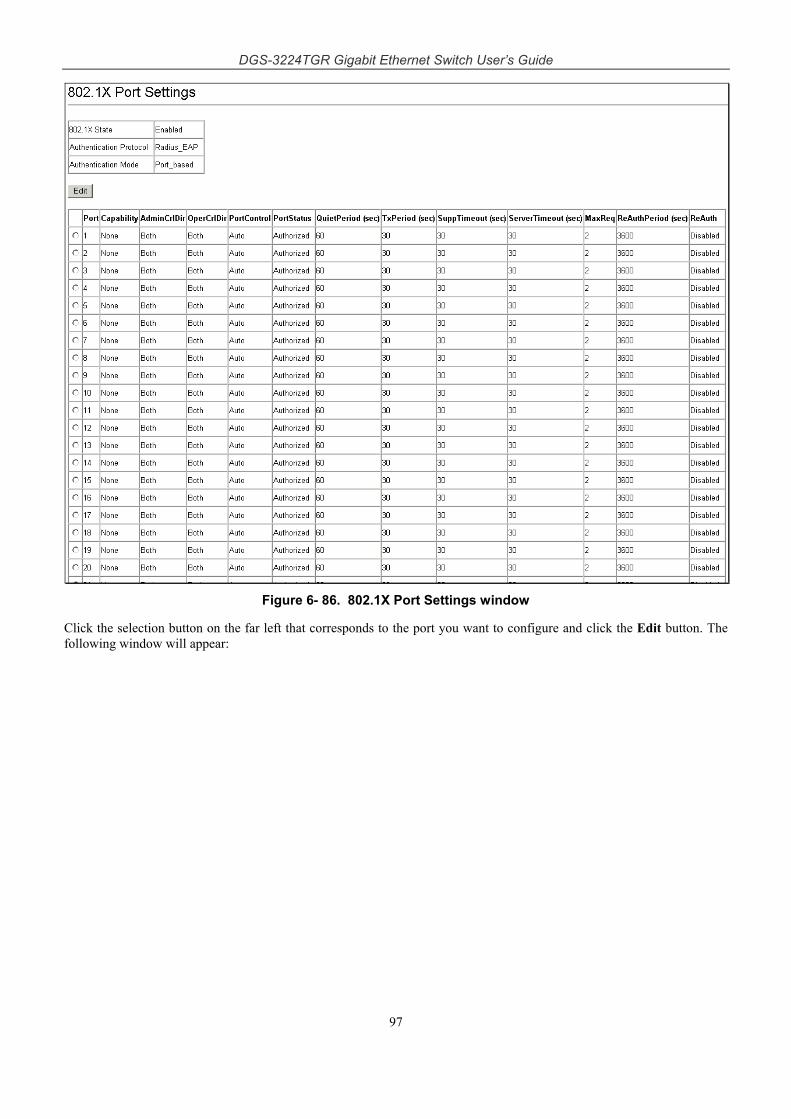
DGS-3224TGR Gigabit Ethernet Switch User’s Guide
97
Figure 6- 86. 802.1X Port Settings window
Click the selection button on the far left that corresponds to the port you want to configure and click the Edit button. The following window will appear:
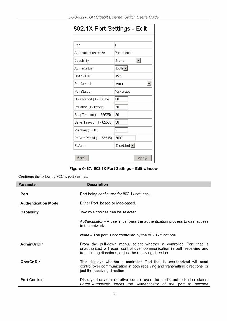
DGS-3224TGR Gigabit Ethernet Switch User’s Guide
98
Figure 6- 87. 802.1X Port Settings – Edit window
Configure the following 802.1x port settings:
Parameter Description
Port Port being configured for 802.1x settings.
Authentication Mode Either Port_based or Mac-based.
Capability Two role choices can be selected:
Authenticator − A user must pass the authentication process to gain access to the network.
None − The port is not controlled by the 802.1x functions.
AdminCrlDir From the pull-down menu, select whether a controlled Port that is unauthorized will exert control over communication in both receiving and transmitting directions, or just the receiving direction.
OperCrlDir This displays whether a controlled Port that is unauthorized will exert control over communication in both receiving and transmitting directions, or just the receiving direction.
Port Control Displays the administrative control over the port’s authorization status. Force_Authorized forces the Authenticator of the port to become
DGS-3224TGR Gigabit Ethernet Switch User’s Guide
99
Authorized. Force_Unauthorized forces the port to become Unauthorized. Auto means the port state reflects the outcome of the authentication exchange between supplicant, authenticator, and authentication.
PortStatus Lists the current status of port, Authorized or Unauthorized.
QuietPeriod (0-65535) Select the time interval between authentication failure and the start of a new authentication attempt.
TxPeriod (1-65535) Select the time to wait for a response from a supplicant (user) to send EAP Request/Identity packets.
SuppTimeout (1-65535) Select the time to wait for a response from a supplicant (user) for all EAP packets, except for the Request/Identity packets.
ServerTimeout (1-65535) Select the length of time to wait for a response from a RADIUS server.
MaxReq (1-10) Select the maximum number of times to retry sending packets to the supplicant.
ReAuthPeriod (1-65535) Select the time interval between successive re-authentications.
ReAuth Enable or disable reauthentication.
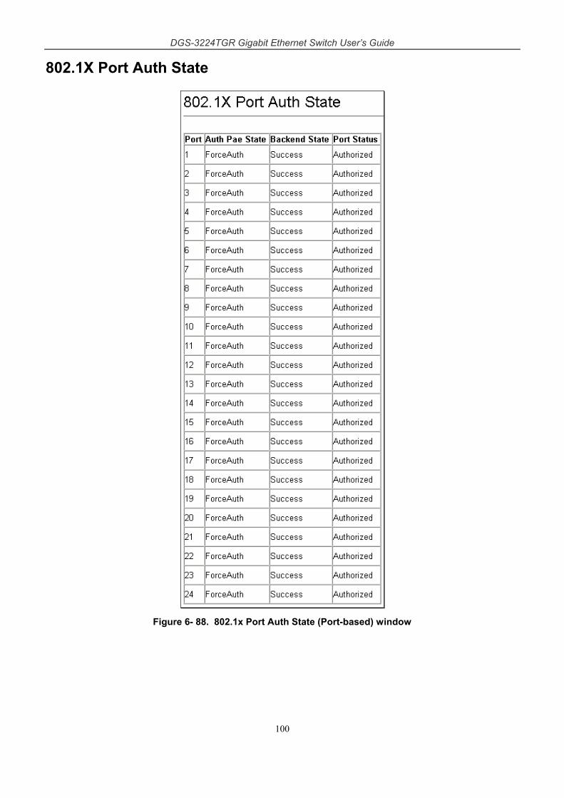
DGS-3224TGR Gigabit Ethernet Switch User’s Guide
100
802.1X Port Auth State
Figure 6- 88. 802.1x Port Auth State (Port-based) window
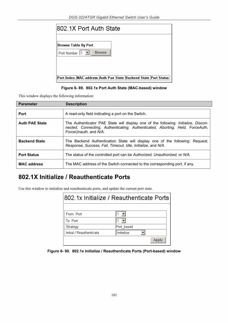
DGS-3224TGR Gigabit Ethernet Switch User’s Guide
101
Figure 6- 89. 802.1x Port Auth State (MAC-based) window
This window displays the following information:
Parameter Description
Port A read-only field indicating a port on the Switch.
Auth PAE State The Authenticator PAE State will display one of the following: Initialize, Discon-nected, Connecting, Authenticating, Authenticated, Aborting, Held, ForceAuth, ForceUnauth, and N/A.
Backend State The Backend Authentication State will display one of the following: Request, Response, Success, Fail, Timeout, Idle, Initialize, and N/A.
Port Status The status of the controlled port can be Authorized, Unauthorized, or N/A.
MAC address The MAC address of the Switch connected to the corresponding port, if any.
802.1X Initialize / Reauthenticate Ports
Use this window to initialize and reauthenticate ports, and update the current port state.
Figure 6- 90. 802.1x Initialize / Reauthenticate Ports (Port-based) window
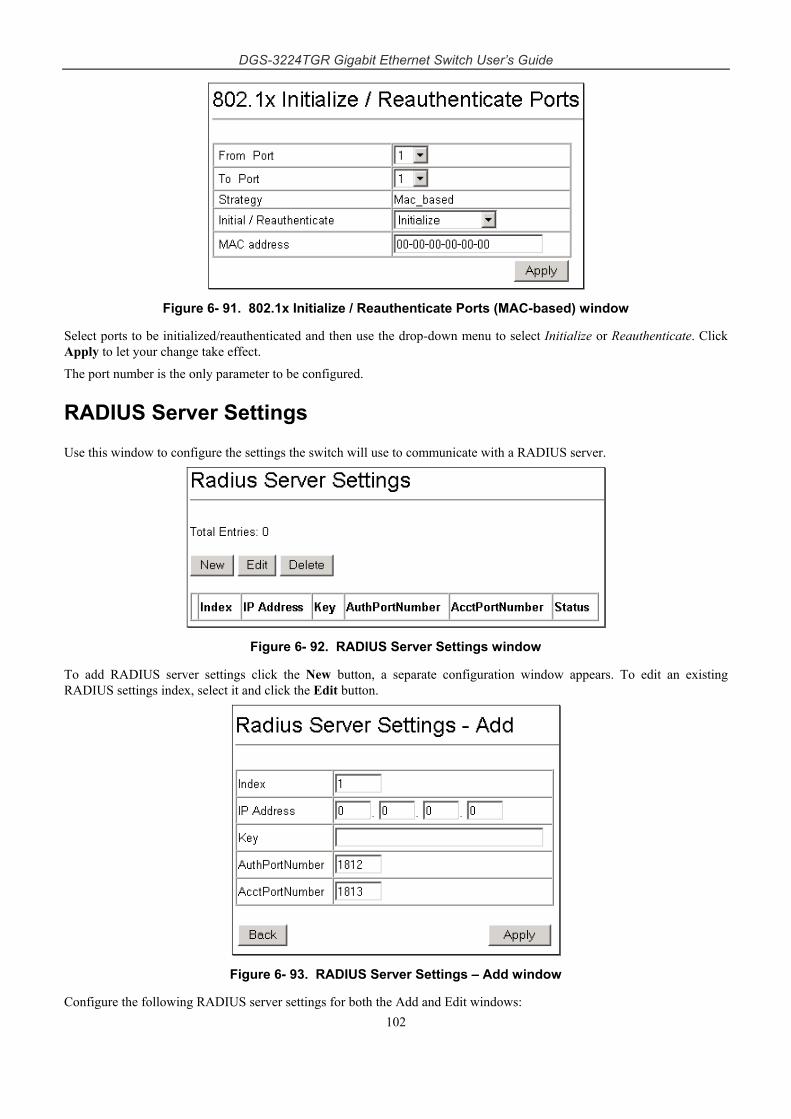
DGS-3224TGR Gigabit Ethernet Switch User’s Guide
102
Figure 6- 91. 802.1x Initialize / Reauthenticate Ports (MAC-based) window
Select ports to be initialized/reauthenticated and then use the drop-down menu to select Initialize or Reauthenticate. Click Apply to let your change take effect.
The port number is the only parameter to be configured.
RADIUS Server Settings
Use this window to configure the settings the switch will use to communicate with a RADIUS server.
Figure 6- 92. RADIUS Server Settings window
To add RADIUS server settings click the New button, a separate configuration window appears. To edit an existing RADIUS settings index, select it and click the Edit button.
Figure 6- 93. RADIUS Server Settings – Add window
Configure the following RADIUS server settings for both the Add and Edit windows:
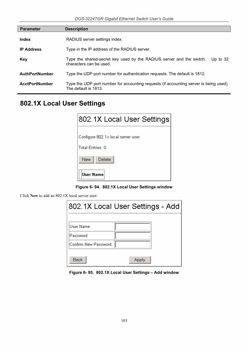
DGS-3224TGR Gigabit Ethernet Switch User’s Guide
103
Parameter Description
Index RADIUS server settings index.
IP Address Type in the IP address of the RADIUS server.
Key Type the shared-secret key used by the RADIUS server and the switch. Up to 32 characters can be used.
AuthPortNumber Type the UDP port number for authentication requests. The default is 1812.
AcctPortNumber Type the UDP port number for accounting requests (if accounting server is being used). The default is 1813.
802.1X Local User Settings
Figure 6- 94. 802.1X Local User Settings window
Click New to add an 802.1X local server user:
Figure 6- 95. 802.1X Local User Settings – Add window
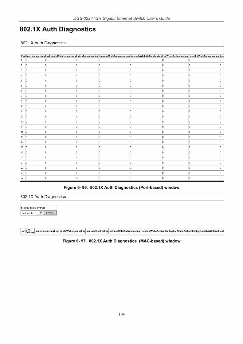
DGS-3224TGR Gigabit Ethernet Switch User’s Guide
104
802.1X Auth Diagnostics
Figure 6- 96. 802.1X Auth Diagnostics (Port-based) window
Figure 6- 97. 802.1X Auth Diagnostics (MAC-based) window
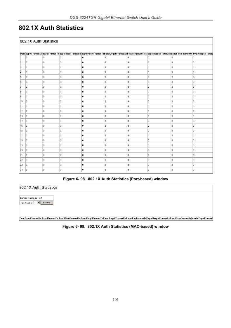
DGS-3224TGR Gigabit Ethernet Switch User’s Guide
105
802.1X Auth Statistics
Figure 6- 98. 802.1X Auth Statistics (Port-based) window
Figure 6- 99. 802.1X Auth Statistics (MAC-based) window
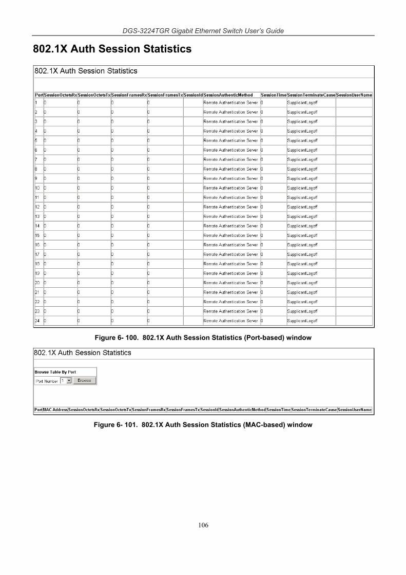
DGS-3224TGR Gigabit Ethernet Switch User’s Guide
106
802.1X Auth Session Statistics
Figure 6- 100. 802.1X Auth Session Statistics (Port-based) window
Figure 6- 101. 802.1X Auth Session Statistics (MAC-based) window
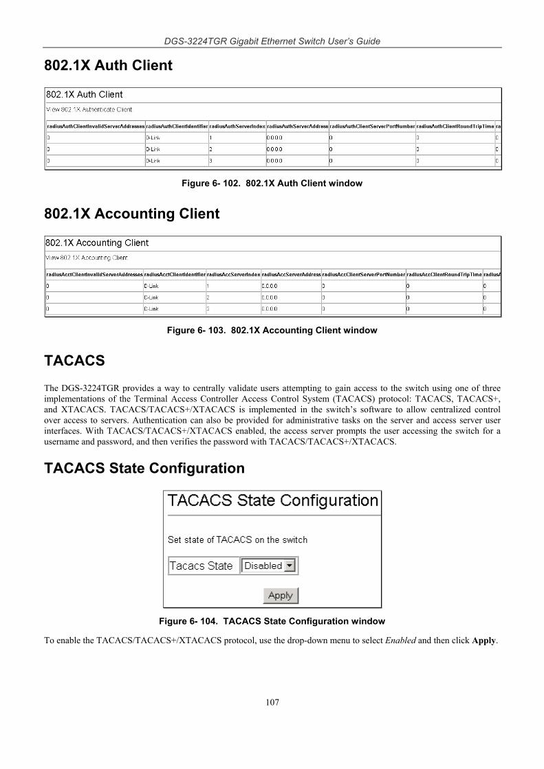
DGS-3224TGR Gigabit Ethernet Switch User’s Guide
107
802.1X Auth Client
Figure 6- 102. 802.1X Auth Client window
802.1X Accounting Client
Figure 6- 103. 802.1X Accounting Client window
TACACS
The DGS-3224TGR provides a way to centrally validate users attempting to gain access to the switch using one of three implementations of the Terminal Access Controller Access Control System (TACACS) protocol: TACACS, TACACS+, and XTACACS. TACACS/TACACS+/XTACACS is implemented in the switch’s software to allow centralized control over access to servers. Authentication can also be provided for administrative tasks on the server and access server user interfaces. With TACACS/TACACS+/XTACACS enabled, the access server prompts the user accessing the switch for a username and password, and then verifies the password with TACACS/TACACS+/XTACACS.
TACACS State Configuration
Figure 6- 104. TACACS State Configuration window
To enable the TACACS/TACACS+/XTACACS protocol, use the drop-down menu to select Enabled and then click Apply.
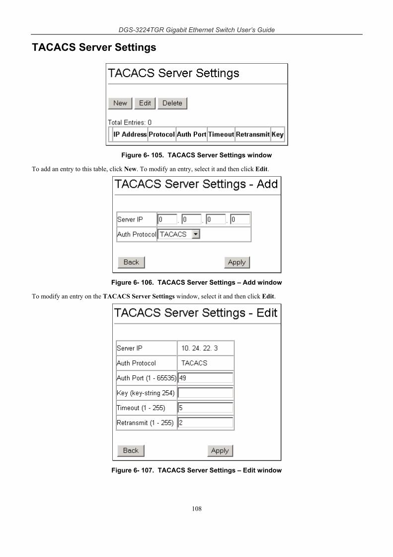
DGS-3224TGR Gigabit Ethernet Switch User’s Guide
108
TACACS Server Settings
Figure 6- 105. TACACS Server Settings window
To add an entry to this table, click New. To modify an entry, select it and then click Edit.
Figure 6- 106. TACACS Server Settings – Add window
To modify an entry on the TACACS Server Settings window, select it and then click Edit.
Figure 6- 107. TACACS Server Settings – Edit window
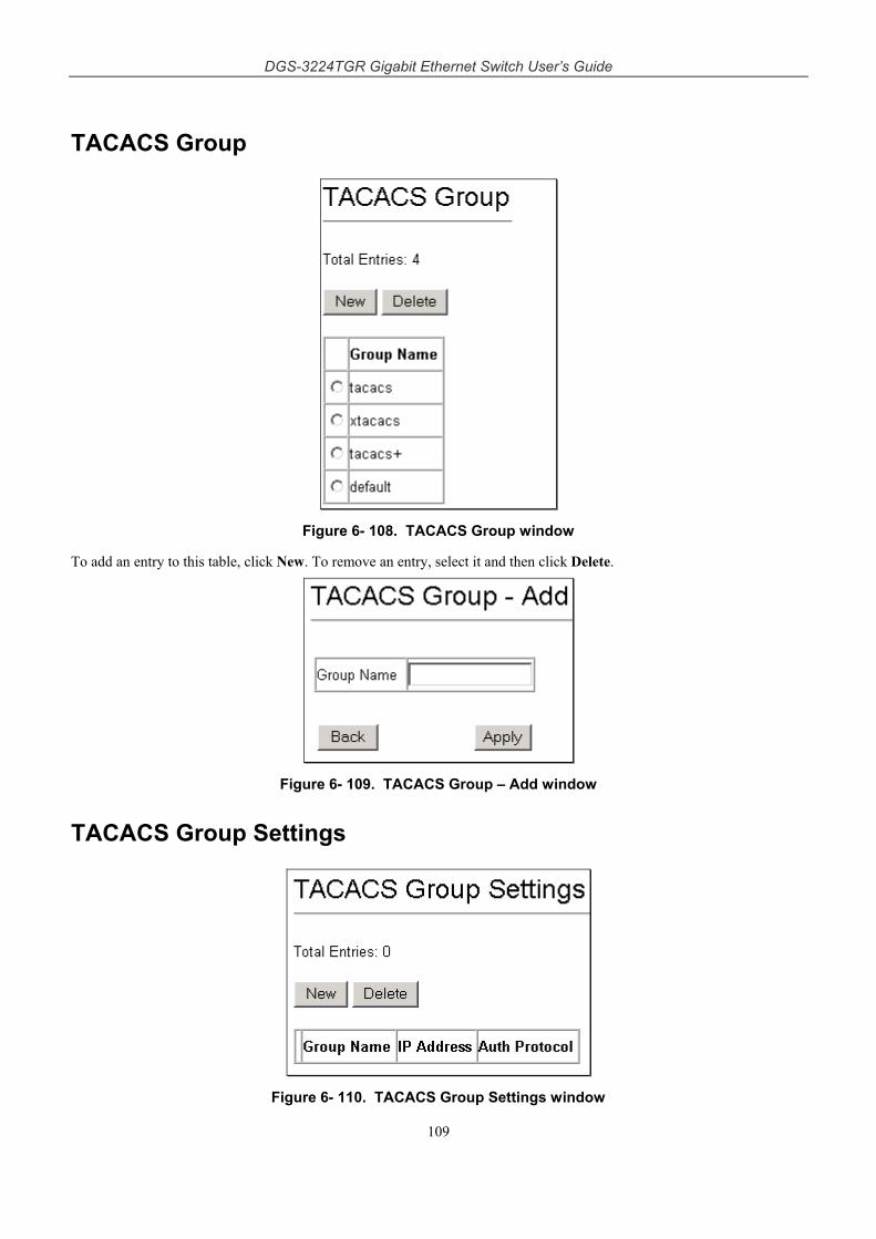
DGS-3224TGR Gigabit Ethernet Switch User’s Guide
109
TACACS Group
Figure 6- 108. TACACS Group window
To add an entry to this table, click New. To remove an entry, select it and then click Delete.
Figure 6- 109. TACACS Group – Add window
TACACS Group Settings
Figure 6- 110. TACACS Group Settings window
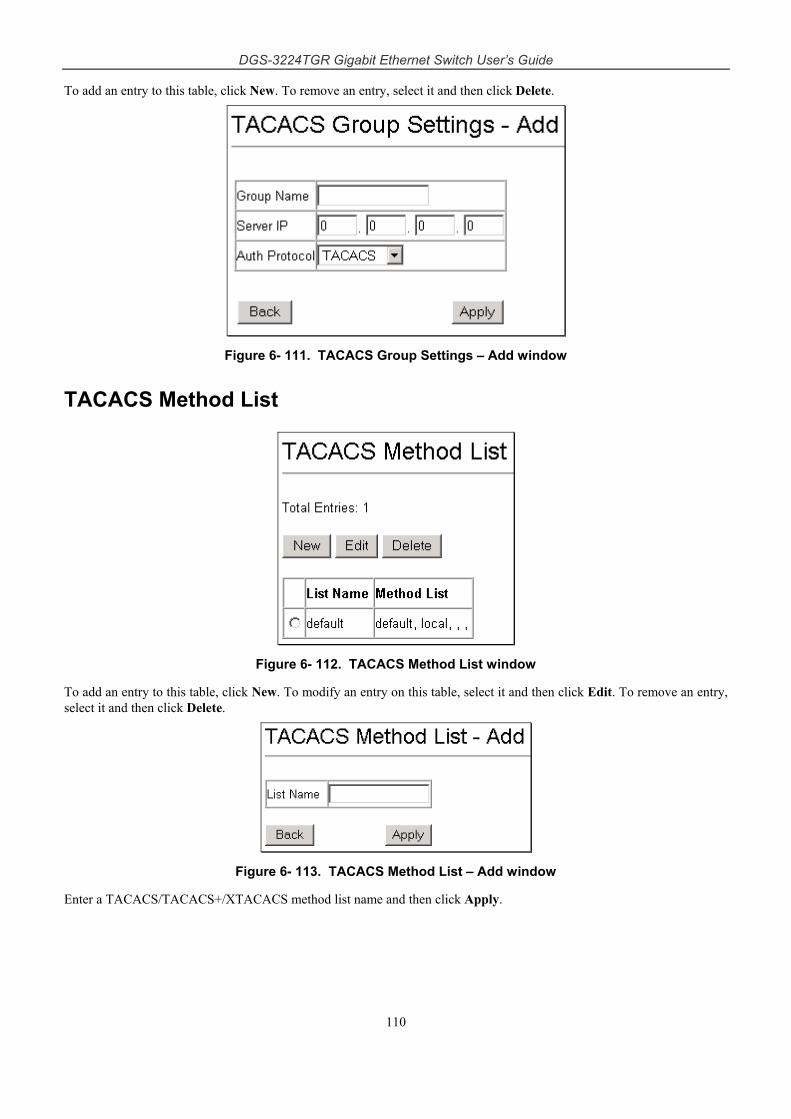
DGS-3224TGR Gigabit Ethernet Switch User’s Guide
110
To add an entry to this table, click New. To remove an entry, select it and then click Delete.
Figure 6- 111. TACACS Group Settings – Add window
TACACS Method List
Figure 6- 112. TACACS Method List window
To add an entry to this table, click New. To modify an entry on this table, select it and then click Edit. To remove an entry, select it and then click Delete.
Figure 6- 113. TACACS Method List – Add window
Enter a TACACS/TACACS+/XTACACS method list name and then click Apply.
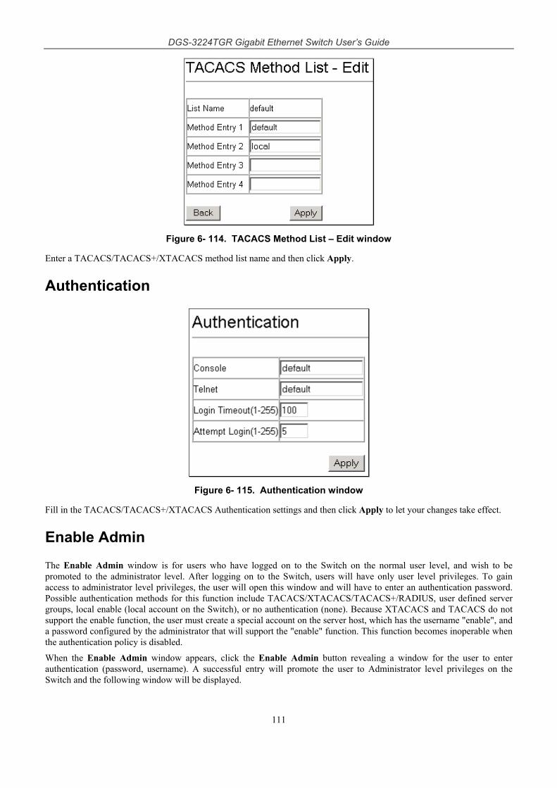
DGS-3224TGR Gigabit Ethernet Switch User’s Guide
111
Figure 6- 114. TACACS Method List – Edit window
Enter a TACACS/TACACS+/XTACACS method list name and then click Apply.
Authentication
Figure 6- 115. Authentication window
Fill in the TACACS/TACACS+/XTACACS Authentication settings and then click Apply to let your changes take effect.
Enable Admin
The Enable Admin window is for users who have logged on to the Switch on the normal user level, and wish to be promoted to the administrator level. After logging on to the Switch, users will have only user level privileges. To gain access to administrator level privileges, the user will open this window and will have to enter an authentication password. Possible authentication methods for this function include TACACS/XTACACS/TACACS+/RADIUS, user defined server groups, local enable (local account on the Switch), or no authentication (none). Because XTACACS and TACACS do not support the enable function, the user must create a special account on the server host, which has the username "enable", and a password configured by the administrator that will support the "enable" function. This function becomes inoperable when the authentication policy is disabled.
When the Enable Admin window appears, click the Enable Admin button revealing a window for the user to enter authentication (password, username). A successful entry will promote the user to Administrator level privileges on the Switch and the following window will be displayed.
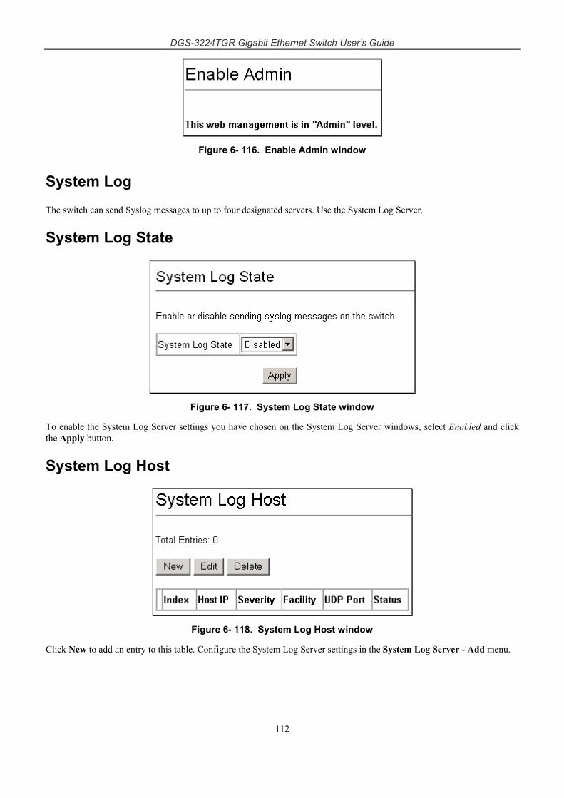
DGS-3224TGR Gigabit Ethernet Switch User’s Guide
112
Figure 6- 116. Enable Admin window
System Log
The switch can send Syslog messages to up to four designated servers. Use the System Log Server.
System Log State
Figure 6- 117. System Log State window
To enable the System Log Server settings you have chosen on the System Log Server windows, select Enabled and click the Apply button.
System Log Host
Figure 6- 118. System Log Host window
Click New to add an entry to this table. Configure the System Log Server settings in the System Log Server - Add menu.
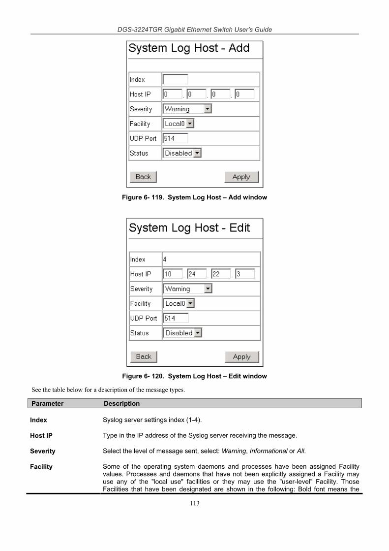
DGS-3224TGR Gigabit Ethernet Switch User’s Guide
113
Figure 6- 119. System Log Host – Add window
Figure 6- 120. System Log Host – Edit window
See the table below for a description of the message types.
Parameter Description
Index Syslog server settings index (1-4).
Host IP Type in the IP address of the Syslog server receiving the message.
Severity Select the level of message sent, select: Warning, Informational or All.
Facility Some of the operating system daemons and processes have been assigned Facility values. Processes and daemons that have not been explicitly assigned a Facility may use any of the "local use" facilities or they may use the "user-level" Facility. Those Facilities that have been designated are shown in the following: Bold font means the
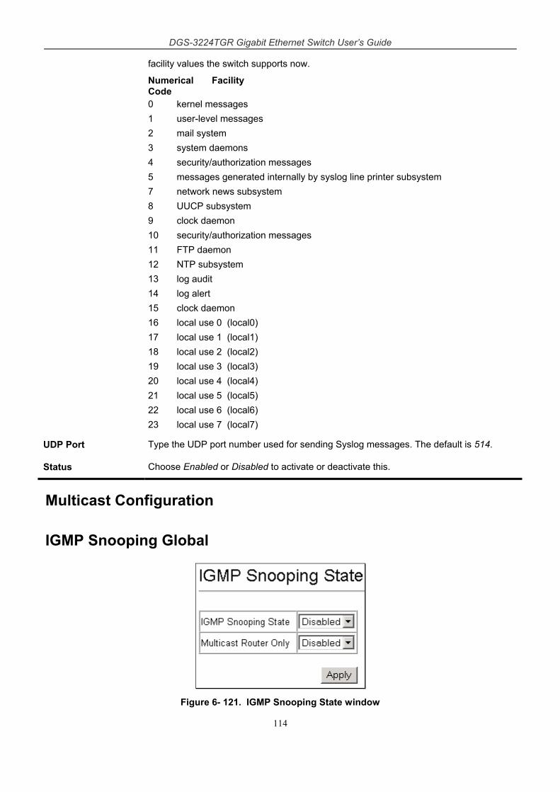
DGS-3224TGR Gigabit Ethernet Switch User’s Guide
114
facility values the switch supports now.
Numerical Facility Code 0 kernel messages 1 user-level messages 2 mail system 3 system daemons 4 security/authorization messages 5 messages generated internally by syslog line printer subsystem 7 network news subsystem 8 UUCP subsystem 9 clock daemon 10 security/authorization messages 11 FTP daemon 12 NTP subsystem 13 log audit 14 log alert 15 clock daemon 16 local use 0 (local0) 17 local use 1 (local1) 18 local use 2 (local2) 19 local use 3 (local3) 20 local use 4 (local4) 21 local use 5 (local5) 22 local use 6 (local6) 23 local use 7 (local7)
UDP Port Type the UDP port number used for sending Syslog messages. The default is 514.
Status Choose Enabled or Disabled to activate or deactivate this.
Multicast Configuration
IGMP Snooping Global
Figure 6- 121. IGMP Snooping State window
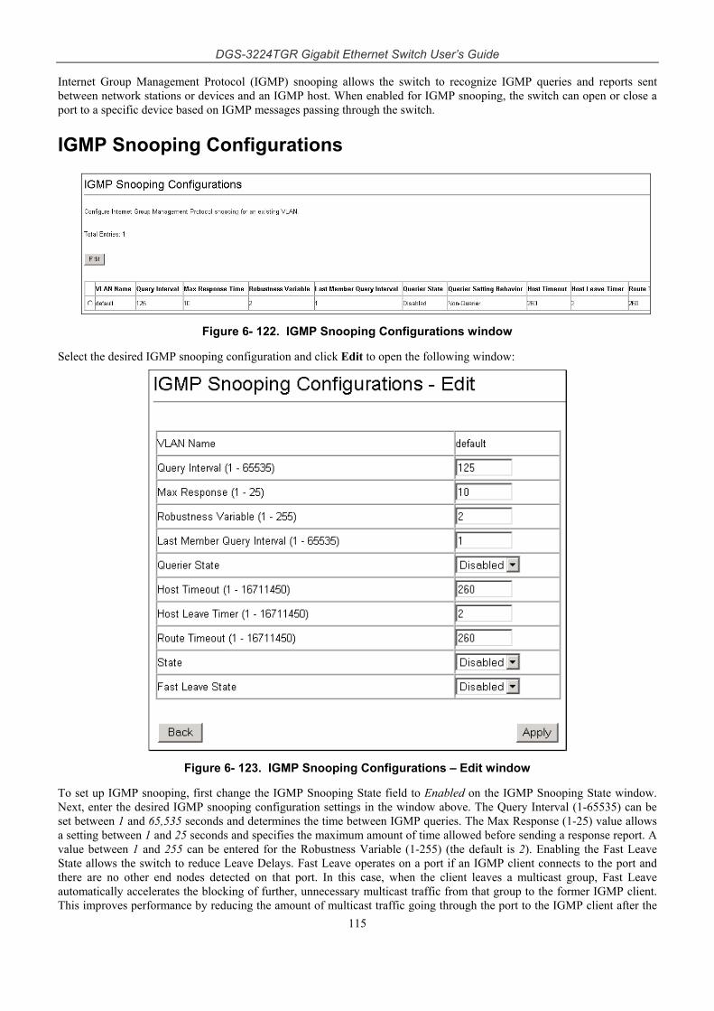
DGS-3224TGR Gigabit Ethernet Switch User’s Guide
115
Internet Group Management Protocol (IGMP) snooping allows the switch to recognize IGMP queries and reports sent between network stations or devices and an IGMP host. When enabled for IGMP snooping, the switch can open or close a port to a specific device based on IGMP messages passing through the switch.
IGMP Snooping Configurations
Figure 6- 122. IGMP Snooping Configurations window
Select the desired IGMP snooping configuration and click Edit to open the following window:
Figure 6- 123. IGMP Snooping Configurations – Edit window
To set up IGMP snooping, first change the IGMP Snooping State field to Enabled on the IGMP Snooping State window. Next, enter the desired IGMP snooping configuration settings in the window above. The Query Interval (1-65535) can be set between 1 and 65,535 seconds and determines the time between IGMP queries. The Max Response (1-25) value allows a setting between 1 and 25 seconds and specifies the maximum amount of time allowed before sending a response report. A value between 1 and 255 can be entered for the Robustness Variable (1-255) (the default is 2). Enabling the Fast Leave State allows the switch to reduce Leave Delays. Fast Leave operates on a port if an IGMP client connects to the port and there are no other end nodes detected on that port. In this case, when the client leaves a multicast group, Fast Leave automatically accelerates the blocking of further, unnecessary multicast traffic from that group to the former IGMP client. This improves performance by reducing the amount of multicast traffic going through the port to the IGMP client after the
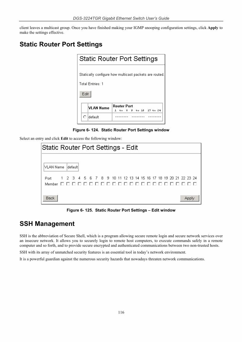
DGS-3224TGR Gigabit Ethernet Switch User’s Guide
116
client leaves a multicast group. Once you have finished making your IGMP snooping configuration settings, click Apply to make the settings effective.
Static Router Port Settings
Figure 6- 124. Static Router Port Settings window
Select an entry and click Edit to access the following window:
Figure 6- 125. Static Router Port Settings – Edit window
SSH Management
SSH is the abbreviation of Secure Shell, which is a program allowing secure remote login and secure network services over an insecure network. It allows you to securely login to remote host computers, to execute commands safely in a remote computer and so forth, and to provide secure encrypted and authenticated communications between two non-trusted hosts.
SSH with its array of unmatched security features is an essential tool in today’s network environment.
It is a powerful guardian against the numerous security hazards that nowadays threaten network communications.
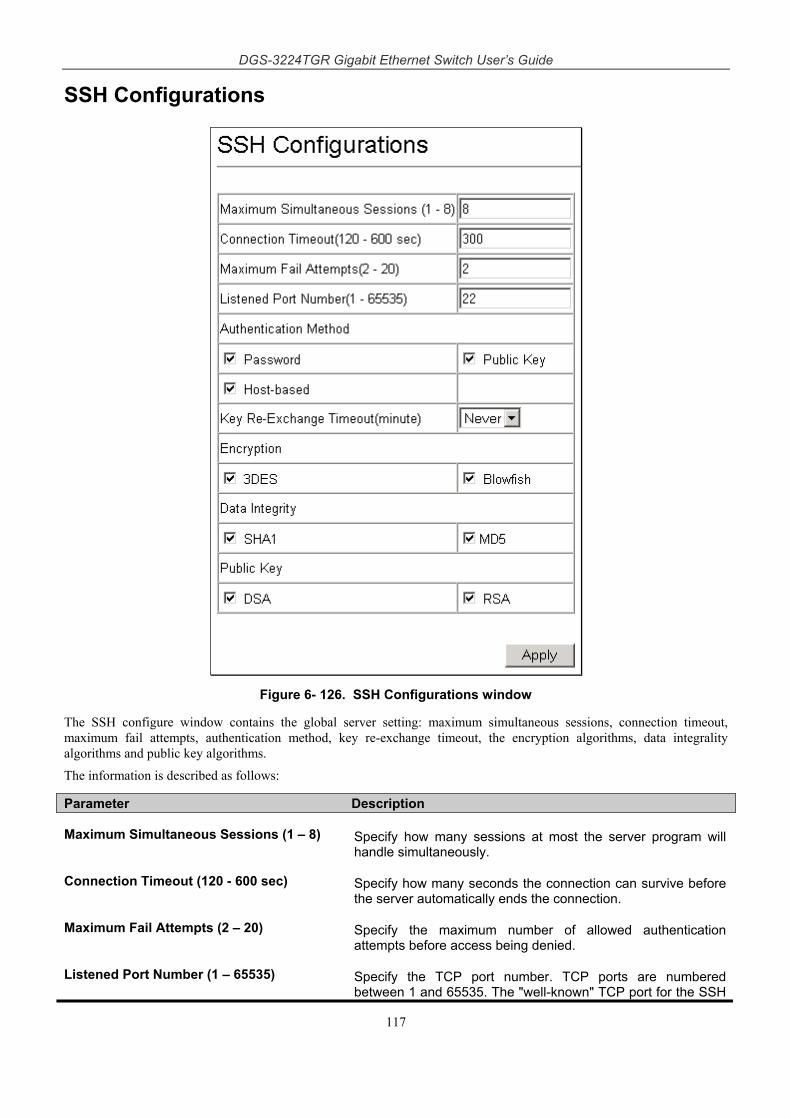
DGS-3224TGR Gigabit Ethernet Switch User’s Guide
117
SSH Configurations
Figure 6- 126. SSH Configurations window
The SSH configure window contains the global server setting: maximum simultaneous sessions, connection timeout, maximum fail attempts, authentication method, key re-exchange timeout, the encryption algorithms, data integrality algorithms and public key algorithms.
The information is described as follows:
Parameter Description
Maximum Simultaneous Sessions (1 – 8) Specify how many sessions at most the server program will handle simultaneously.
Connection Timeout (120 - 600 sec) Specify how many seconds the connection can survive before the server automatically ends the connection.
Maximum Fail Attempts (2 – 20) Specify the maximum number of allowed authentication attempts before access being denied.
Listened Port Number (1 – 65535) Specify the TCP port number. TCP ports are numbered between 1 and 65535. The "well-known" TCP port for the SSH
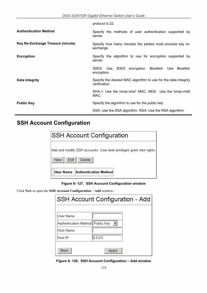
DGS-3224TGR Gigabit Ethernet Switch User’s Guide
118
protocol is 22.
Authentication Method Specify the methods of user authentication supported by server.
Key Re-Exchange Timeout (minute) Specify how many minutes the parties must process key re-exchange.
Encryption Specify the algorithm to use for encryption supported by server.
3DES: Use 3DES encryption. Blowfish: Use Blowfish encryption.
Data Integrity Specify the desired MAC algorithm to use for the data integrity verification.
SHA-1: Use the hmac-sha1 MAC. MD5: Use the hmac-md5 MAC.
Public Key Specify the algorithm to use for the public key.
DSA: Use the DSA algorithm. RSA: Use the RSA algorithm.
SSH Account Configuration
Figure 6- 127. SSH Account Configuration window
Click New to open the SSH Account Configuration – Add window:
Figure 6- 128. SSH Account Configuration – Add window
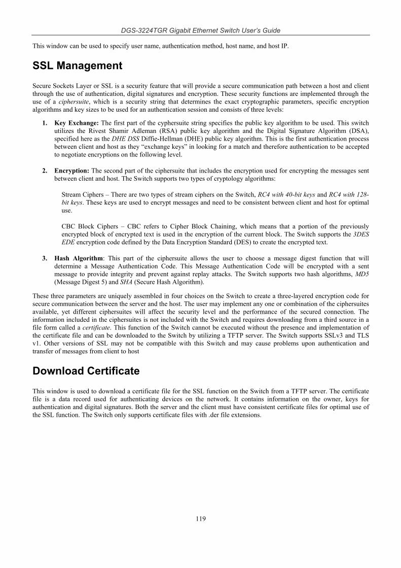
DGS-3224TGR Gigabit Ethernet Switch User’s Guide
119
This window can be used to specify user name, authentication method, host name, and host IP.
SSL Management
Secure Sockets Layer or SSL is a security feature that will provide a secure communication path between a host and client through the use of authentication, digital signatures and encryption. These security functions are implemented through the use of a ciphersuite, which is a security string that determines the exact cryptographic parameters, specific encryption algorithms and key sizes to be used for an authentication session and consists of three levels:
1. Key Exchange: The first part of the cyphersuite string specifies the public key algorithm to be used. This switch utilizes the Rivest Shamir Adleman (RSA) public key algorithm and the Digital Signature Algorithm (DSA), specified here as the DHE DSS Diffie-Hellman (DHE) public key algorithm. This is the first authentication process between client and host as they “exchange keys” in looking for a match and therefore authentication to be accepted to negotiate encryptions on the following level.
2. Encryption: The second part of the ciphersuite that includes the encryption used for encrypting the messages sent between client and host. The Switch supports two types of cryptology algorithms:
Stream Ciphers – There are two types of stream ciphers on the Switch, RC4 with 40-bit keys and RC4 with 128-bit keys. These keys are used to encrypt messages and need to be consistent between client and host for optimal use.
CBC Block Ciphers – CBC refers to Cipher Block Chaining, which means that a portion of the previously encrypted block of encrypted text is used in the encryption of the current block. The Switch supports the 3DES EDE encryption code defined by the Data Encryption Standard (DES) to create the encrypted text.
3. Hash Algorithm: This part of the ciphersuite allows the user to choose a message digest function that will determine a Message Authentication Code. This Message Authentication Code will be encrypted with a sent message to provide integrity and prevent against replay attacks. The Switch supports two hash algorithms, MD5 (Message Digest 5) and SHA (Secure Hash Algorithm).
These three parameters are uniquely assembled in four choices on the Switch to create a three-layered encryption code for secure communication between the server and the host. The user may implement any one or combination of the ciphersuites available, yet different ciphersuites will affect the security level and the performance of the secured connection. The information included in the ciphersuites is not included with the Switch and requires downloading from a third source in a file form called a certificate. This function of the Switch cannot be executed without the presence and implementation of the certificate file and can be downloaded to the Switch by utilizing a TFTP server. The Switch supports SSLv3 and TLS v1. Other versions of SSL may not be compatible with this Switch and may cause problems upon authentication and transfer of messages from client to host
Download Certificate
This window is used to download a certificate file for the SSL function on the Switch from a TFTP server. The certificate file is a data record used for authenticating devices on the network. It contains information on the owner, keys for authentication and digital signatures. Both the server and the client must have consistent certificate files for optimal use of the SSL function. The Switch only supports certificate files with .der file extensions.
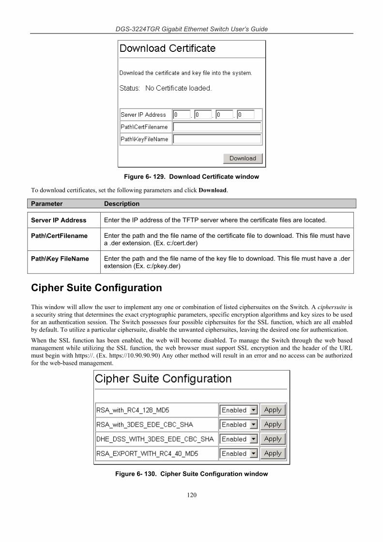
DGS-3224TGR Gigabit Ethernet Switch User’s Guide
120
Figure 6- 129. Download Certificate window
To download certificates, set the following parameters and click Download.
Parameter Description
Server IP Address Enter the IP address of the TFTP server where the certificate files are located.
Path\CertFilename Enter the path and the file name of the certificate file to download. This file must have a .der extension. (Ex. c:/cert.der)
Path\Key FileName Enter the path and the file name of the key file to download. This file must have a .der extension (Ex. c:/pkey.der)
Cipher Suite Configuration
This window will allow the user to implement any one or combination of listed ciphersuites on the Switch. A ciphersuite is a security string that determines the exact cryptographic parameters, specific encryption algorithms and key sizes to be used for an authentication session. The Switch possesses four possible ciphersuites for the SSL function, which are all enabled by default. To utilize a particular ciphersuite, disable the unwanted ciphersuites, leaving the desired one for authentication.
When the SSL function has been enabled, the web will become disabled. To manage the Switch through the web based management while utilizing the SSL function, the web browser must support SSL encryption and the header of the URL must begin with https://. (Ex. https://10.90.90.90) Any other method will result in an error and no access can be authorized for the web-based management.
Figure 6- 130. Cipher Suite Configuration window
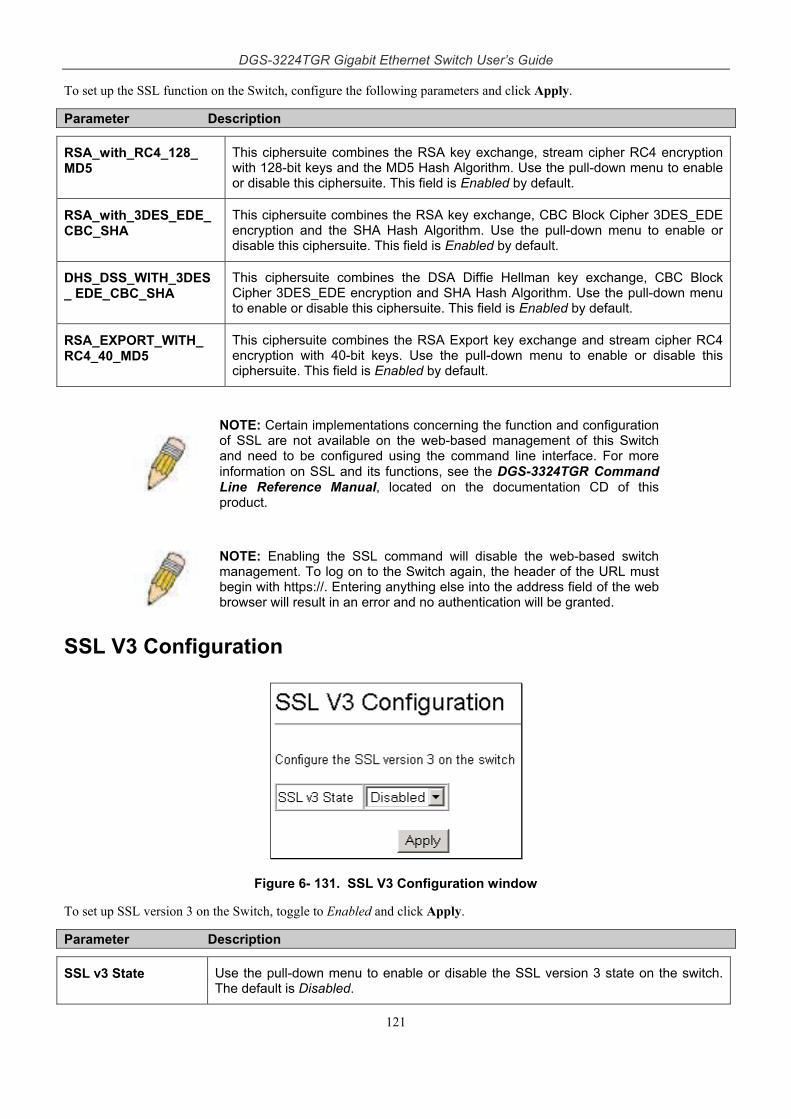
DGS-3224TGR Gigabit Ethernet Switch User’s Guide
121
To set up the SSL function on the Switch, configure the following parameters and click Apply.
Parameter Description
RSA_with_RC4_128_ MD5
This ciphersuite combines the RSA key exchange, stream cipher RC4 encryption with 128-bit keys and the MD5 Hash Algorithm. Use the pull-down menu to enable or disable this ciphersuite. This field is Enabled by default.
RSA_with_3DES_EDE_ CBC_SHA
This ciphersuite combines the RSA key exchange, CBC Block Cipher 3DES_EDE encryption and the SHA Hash Algorithm. Use the pull-down menu to enable or disable this ciphersuite. This field is Enabled by default.
DHS_DSS_WITH_3DES_ EDE_CBC_SHA
This ciphersuite combines the DSA Diffie Hellman key exchange, CBC Block Cipher 3DES_EDE encryption and SHA Hash Algorithm. Use the pull-down menu to enable or disable this ciphersuite. This field is Enabled by default.
RSA_EXPORT_WITH_ RC4_40_MD5
This ciphersuite combines the RSA Export key exchange and stream cipher RC4 encryption with 40-bit keys. Use the pull-down menu to enable or disable this ciphersuite. This field is Enabled by default.
NOTE: Certain implementations concerning the function and configuration of SSL are not available on the web-based management of this Switch and need to be configured using the command line interface. For more information on SSL and its functions, see the DGS-3324TGR Command Line Reference Manual, located on the documentation CD of this product.
NOTE: Enabling the SSL command will disable the web-based switch management. To log on to the Switch again, the header of the URL must begin with https://. Entering anything else into the address field of the web browser will result in an error and no authentication will be granted.
SSL V3 Configuration
Figure 6- 131. SSL V3 Configuration window
To set up SSL version 3 on the Switch, toggle to Enabled and click Apply.
Parameter Description
SSL v3 State Use the pull-down menu to enable or disable the SSL version 3 state on the switch. The default is Disabled.
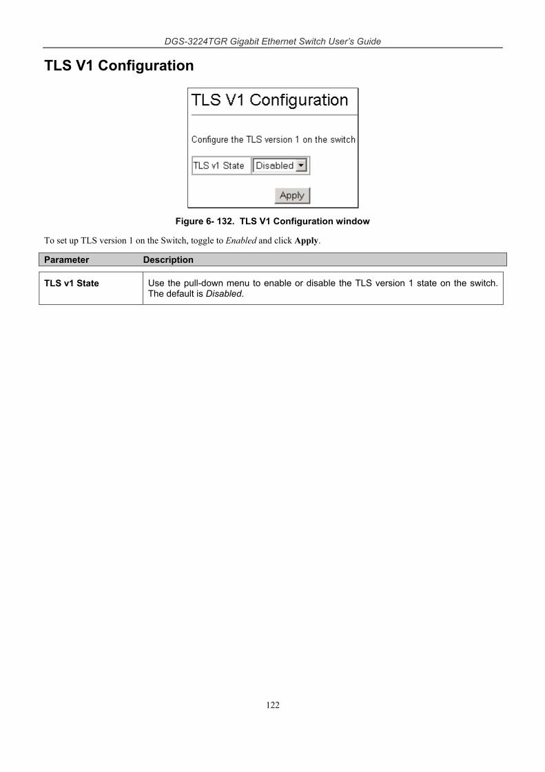
DGS-3224TGR Gigabit Ethernet Switch User’s Guide
122
TLS V1 Configuration
Figure 6- 132. TLS V1 Configuration window
To set up TLS version 1 on the Switch, toggle to Enabled and click Apply.
Parameter Description
TLS v1 State Use the pull-down menu to enable or disable the TLS version 1 state on the switch. The default is Disabled.
DGS-3224TGR Gigabit Ethernet Switch User’s Guide
123
7 Single IP Management
SIM Settings
Topology
Firmware Upgrade
Configuration Backup/Restore
SIM Settings
Simply put, D-Link Single IP Management is a concept that will stack Switches together over Ethernet instead of using stacking ports or modules. There are some advantages in implementing the "Single IP Management" feature:
1. SIM can simplify management of small workgroups or wiring closets while scaling the network to handle increased bandwidth demand.
2. SIM can reduce the number of IP address needed in your network.
3. SIM can eliminate any specialized cables for stacking connectivity and remove the distance barriers that typically limit your topology options when using other stacking technology.
Switches using D-Link Single IP Management (labeled here as SIM) must conform to the following rules:
SIM is an optional feature on the Switch and can easily be enabled or disabled through the Command Line Interface or Web Interface. SIM grouping has no effect on the normal operation of the Switch in the user's network.
There are three classifications for Switches using SIM. The Commander Switch (CS), which is the master Switch of the group, Member Switch (MS), which is a Switch that is recognized by the CS a member of a SIM group, and a Candidate Switch (CaS), which is a Switch that has a physical link to the SIM group but has not been recognized by the CS as a member of the SIM group.
A SIM group can only have one Commander Switch (CS).
All Switches in a particular SIM group must be in the same IP subnet (broadcast domain). Members of a SIM group cannot cross a router.
A SIM group accepts up to 32 Switches (numbered 0-31), including the Commander Switch (numbered 0).
There is no limit to the number of SIM groups in the same IP subnet (broadcast domain), however a single Switch can only belong to one group.
If multiple VLANs are configured, the SIM group will only utilize the default VLAN on any Switch.
SIM allows intermediate devices that do not support SIM. This enables the user to manage Switches that are more than one hop away from the CS.
The SIM group is a group of Switches that are managed as a single entity. The DGS-3224TGRmay take on three different roles:
1. Commander Switch (CS) - This is a Switch that has been manually configured as the controlling device for a group, and takes on the following characteristics:
It has an IP Address.
It is not a command Switch or member Switch of another Single IP group.
DGS-3224TGR Gigabit Ethernet Switch User’s Guide
124
It is connected to the member Switches through its management VLAN.
2. Member Switch (MS) - This is a Switch that has joined a single IP group and is accessible from the CS, and it takes on the following characteristics:
It is not a CS or MS of another IP group.
It is connected to the CS through the CS management VLAN.
3. Candidate Switch(CaS) - This is a Switch that is ready to join a SIM group but is not yet a member of the SIM group. The Candidate Switch may join the SIM group through an automatic function of the DGS-3224TGR, or by manually configuring it to be a MS of a SIM group. A Switch configured as a CaS is not a member of a SIM group and will take on the following characteristics:
It is not a CS or MS of another Single IP group.
It is connected to the CS through the CS management VLAN
The following rules also apply to the above roles:
Each device begins in a Commander state.
CS's must change their role to CaS and then to MS, to become a MS of a SIM group. Thus the CS cannot directly be converted to a MS.
The user can manually configure a CS to become a CaS.
A MS can become a CaS by:
Being configured as a CaS through the CS.
If report packets from the CS to the MS time out.
The user can manually configure a CaS to become a CS
The CaS can be configured through the CS to become a MS.
After configuring one Switch to operate as the CS of a SIM group, additional DGS-3224TGRSwitches may join the group either by an automatic method or by manually configuring the Switch to be a MS. The CS will then serve as the in band entry point for access to the MS. The CS's IP address will become the path to all MS's of the group and the CS's Administrator's password, and/or authentication will control access to all MS's of the SIM group.
With SIM enabled, the applications in the CS will redirect the packet instead of executing the packets. The applications will decode the packet from the administrator, modify some data, then send it to the MS. After execution, the CS may receive a response packet from the MS, which it will encode and send it back to the administrator.
When a CaS becomes a MS, it automatically becomes a member of the first SNMP community (include read/write and read only) to which the CS belongs. However, if a MS has its own IP address, it can belong to SNMP communities to which other Switches in the group, including the CS, do not belong.
SIM Using the Web Interface
All DGS-3224TGR Switches are set as Candidate (CaS) Switches as their factory default configuration and Single IP Management will be disabled. To enable SIM for the Switch using the Web interface, go to the Single IP Management folder and click the SIM Settings link, revealing the following window.
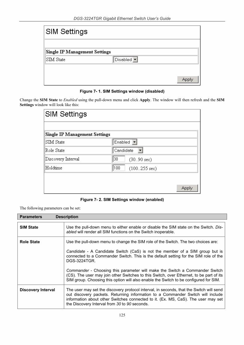
DGS-3224TGR Gigabit Ethernet Switch User’s Guide
125
Figure 7- 1. SIM Settings window (disabled)
Change the SIM State to Enabled using the pull-down menu and click Apply. The window will then refresh and the SIM Settings window will look like this:
Figure 7- 2. SIM Settings window (enabled)
The following parameters can be set:
Parameters Description
SIM State Use the pull-down menu to either enable or disable the SIM state on the Switch. Dis-abled will render all SIM functions on the Switch inoperable.
Role State Use the pull-down menu to change the SIM role of the Switch. The two choices are:
Candidate - A Candidate Switch (CaS) is not the member of a SIM group but is connected to a Commander Switch. This is the default setting for the SIM role of the DGS-3224TGR.
Commander - Choosing this parameter will make the Switch a Commander Switch (CS). The user may join other Switches to this Switch, over Ethernet, to be part of its SIM group. Choosing this option will also enable the Switch to be configured for SIM.
Discovery Interval The user may set the discovery protocol interval, in seconds, that the Switch will send out discovery packets. Returning information to a Commander Switch will include information about other Switches connected to it. (Ex. MS, CaS). The user may set the Discovery Interval from 30 to 90 seconds.
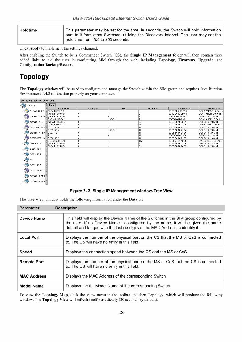
DGS-3224TGR Gigabit Ethernet Switch User’s Guide
126
Holdtime This parameter may be set for the time, in seconds, the Switch will hold information sent to it from other Switches, utilizing the Discovery Interval. The user may set the hold time from 100 to 255 seconds.
Click Apply to implement the settings changed.
After enabling the Switch to be a Commander Switch (CS), the Single IP Management folder will then contain three added links to aid the user in configuring SIM through the web, including Topology, Firmware Upgrade, and Configuration Backup/Restore.
Topology
The Topology window will be used to configure and manage the Switch within the SIM group and requires Java Runtime Environment 1.4.2 to function properly on your computer.
Figure 7- 3. Single IP Management window-Tree View
The Tree View window holds the following information under the Data tab:
Parameter Description
Device Name This field will display the Device Name of the Switches in the SIM group configured by the user. If no Device Name is configured by the name, it will be given the name default and tagged with the last six digits of the MAC Address to identify it.
Local Port Displays the number of the physical port on the CS that the MS or CaS is connected to. The CS will have no entry in this field.
Speed Displays the connection speed between the CS and the MS or CaS.
Remote Port Displays the number of the physical port on the MS or CaS that the CS is connected to. The CS will have no entry in this field.
MAC Address Displays the MAC Address of the corresponding Switch.
Model Name Displays the full Model Name of the corresponding Switch.
To view the Topology Map, click the View menu in the toolbar and then Topology, which will produce the following window. The Topology View will refresh itself periodically (20 seconds by default).
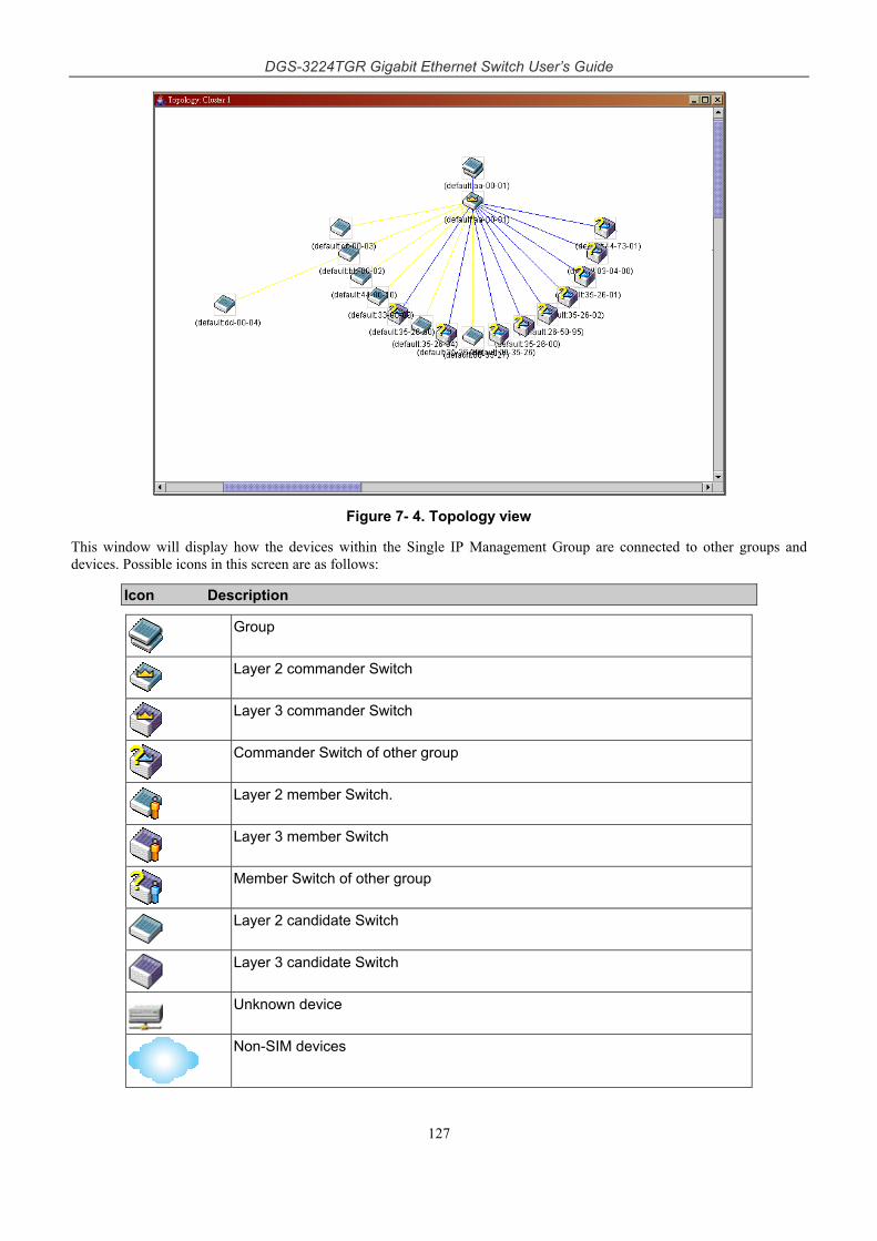
DGS-3224TGR Gigabit Ethernet Switch User’s Guide
127
Figure 7- 4. Topology view
This window will display how the devices within the Single IP Management Group are connected to other groups and devices. Possible icons in this screen are as follows:
Icon Description
Group
Layer 2 commander Switch
Layer 3 commander Switch
Commander Switch of other group
Layer 2 member Switch.
Layer 3 member Switch
Member Switch of other group
Layer 2 candidate Switch
Layer 3 candidate Switch
Unknown device
Non-SIM devices
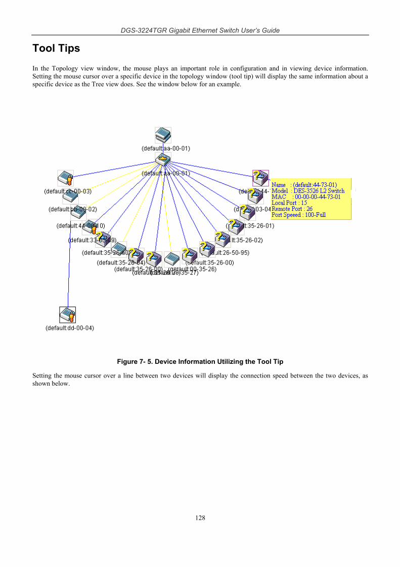
DGS-3224TGR Gigabit Ethernet Switch User’s Guide
128
Tool Tips
In the Topology view window, the mouse plays an important role in configuration and in viewing device information. Setting the mouse cursor over a specific device in the topology window (tool tip) will display the same information about a specific device as the Tree view does. See the window below for an example.
Figure 7- 5. Device Information Utilizing the Tool Tip
Setting the mouse cursor over a line between two devices will display the connection speed between the two devices, as shown below.
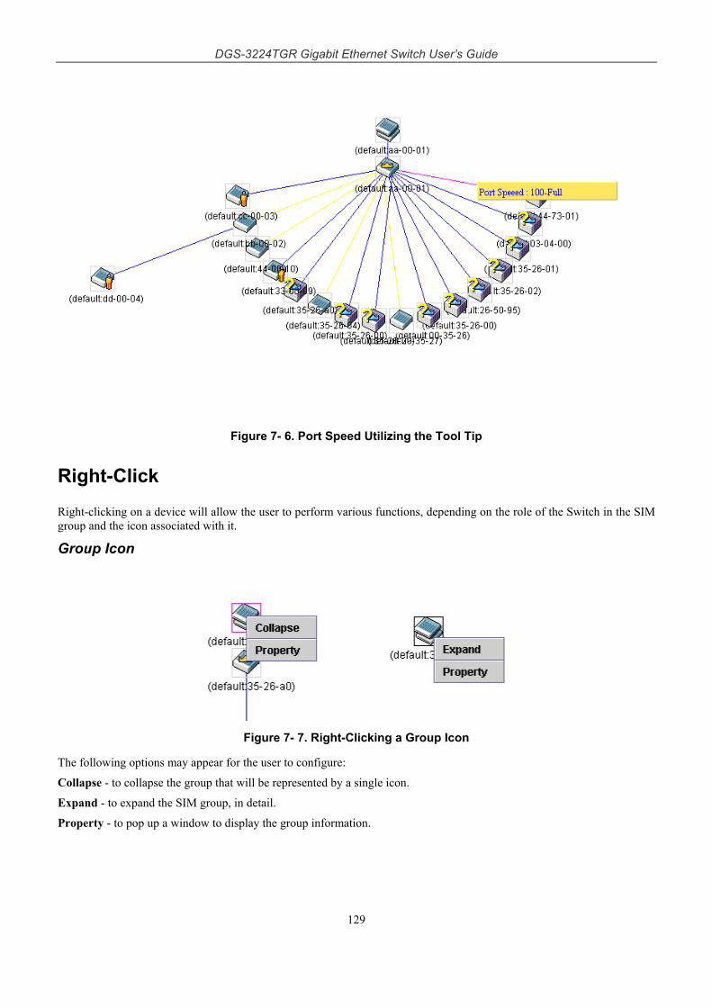
DGS-3224TGR Gigabit Ethernet Switch User’s Guide
129
Figure 7- 6. Port Speed Utilizing the Tool Tip
Right-Click
Right-clicking on a device will allow the user to perform various functions, depending on the role of the Switch in the SIM group and the icon associated with it.
Group Icon
Figure 7- 7. Right-Clicking a Group Icon
The following options may appear for the user to configure:
Collapse - to collapse the group that will be represented by a single icon.
Expand - to expand the SIM group, in detail.
Property - to pop up a window to display the group information.
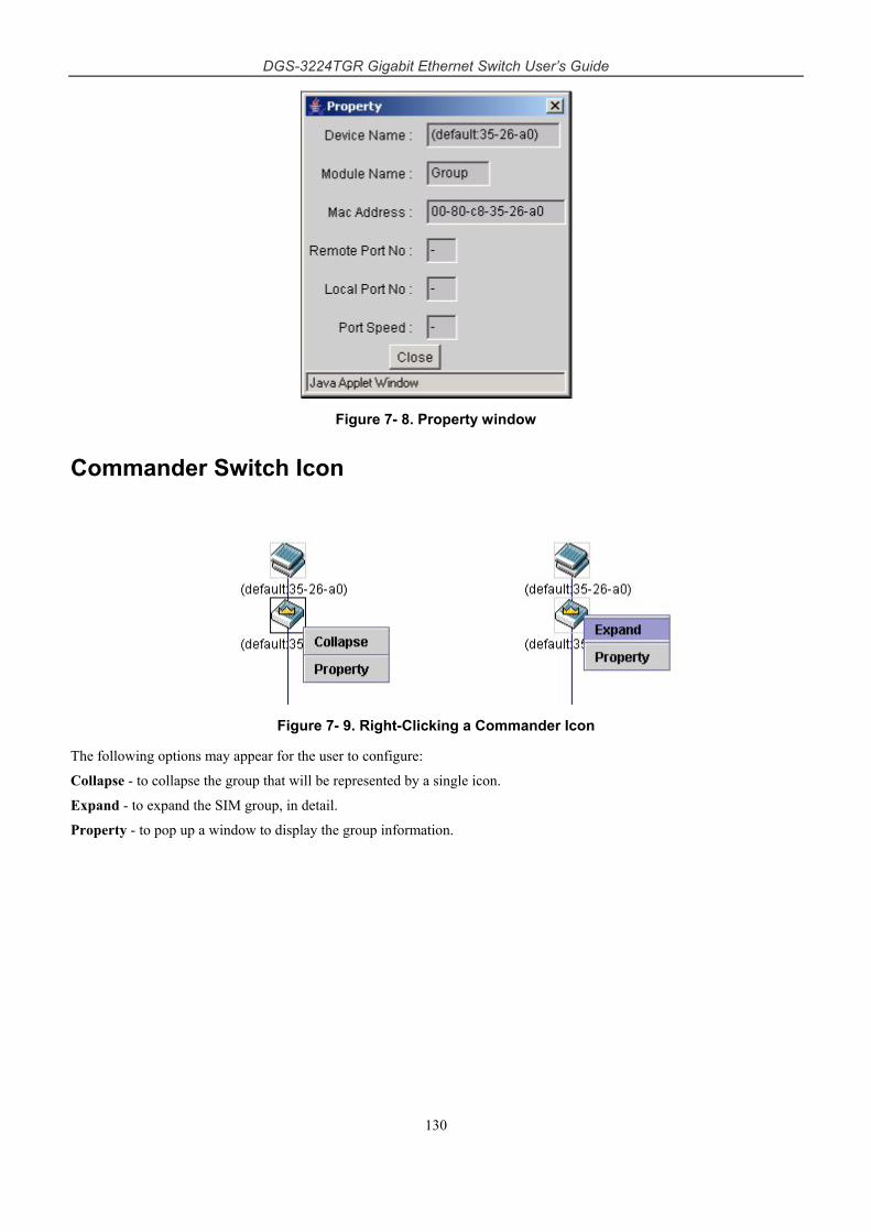
DGS-3224TGR Gigabit Ethernet Switch User’s Guide
130
Figure 7- 8. Property window
Commander Switch Icon
Figure 7- 9. Right-Clicking a Commander Icon
The following options may appear for the user to configure:
Collapse - to collapse the group that will be represented by a single icon.
Expand - to expand the SIM group, in detail.
Property - to pop up a window to display the group information.
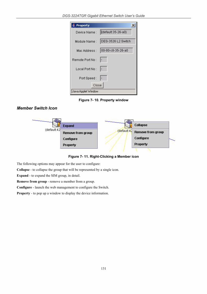
DGS-3224TGR Gigabit Ethernet Switch User’s Guide
131
Figure 7- 10. Property window
Member Switch Icon
Figure 7- 11. Right-Clicking a Member icon
The following options may appear for the user to configure:
Collapse - to collapse the group that will be represented by a single icon.
Expand - to expand the SIM group, in detail.
Remove from group - remove a member from a group.
Configure - launch the web management to configure the Switch.
Property - to pop up a window to display the device information.
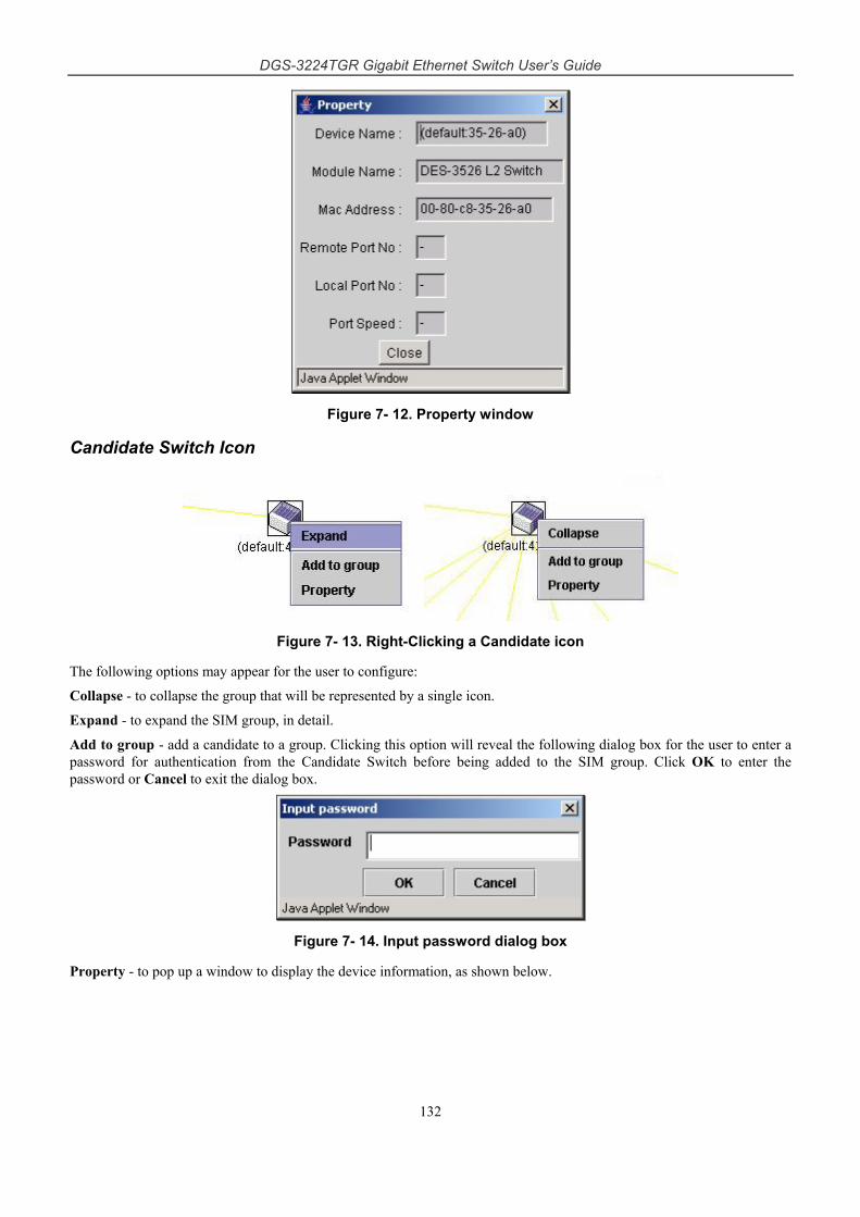
DGS-3224TGR Gigabit Ethernet Switch User’s Guide
132
Figure 7- 12. Property window
Candidate Switch Icon
Figure 7- 13. Right-Clicking a Candidate icon
The following options may appear for the user to configure:
Collapse - to collapse the group that will be represented by a single icon.
Expand - to expand the SIM group, in detail.
Add to group - add a candidate to a group. Clicking this option will reveal the following dialog box for the user to enter a password for authentication from the Candidate Switch before being added to the SIM group. Click OK to enter the password or Cancel to exit the dialog box.
Figure 7- 14. Input password dialog box
Property - to pop up a window to display the device information, as shown below.
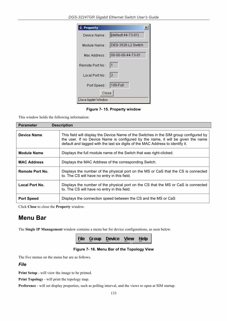
DGS-3224TGR Gigabit Ethernet Switch User’s Guide
133
Figure 7- 15. Property window
This window holds the following information:
Parameter Description
Device Name This field will display the Device Name of the Switches in the SIM group configured by the user. If no Device Name is configured by the name, it will be given the name default and tagged with the last six digits of the MAC Address to identify it.
Module Name Displays the full module name of the Switch that was right-clicked.
MAC Address Displays the MAC Address of the corresponding Switch.
Remote Port No. Displays the number of the physical port on the MS or CaS that the CS is connected to. The CS will have no entry in this field.
Local Port No. Displays the number of the physical port on the CS that the MS or CaS is connected to. The CS will have no entry in this field.
Port Speed Displays the connection speed between the CS and the MS or CaS
Click Close to close the Property window.
Menu Bar
The Single IP Management window contains a menu bar for device configurations, as seen below.
Figure 7- 16. Menu Bar of the Topology View
The five menus on the menu bar are as follows.
File
Print Setup - will view the image to be printed.
Print Topology - will print the topology map.
Preference - will set display properties, such as polling interval, and the views to open at SIM startup.
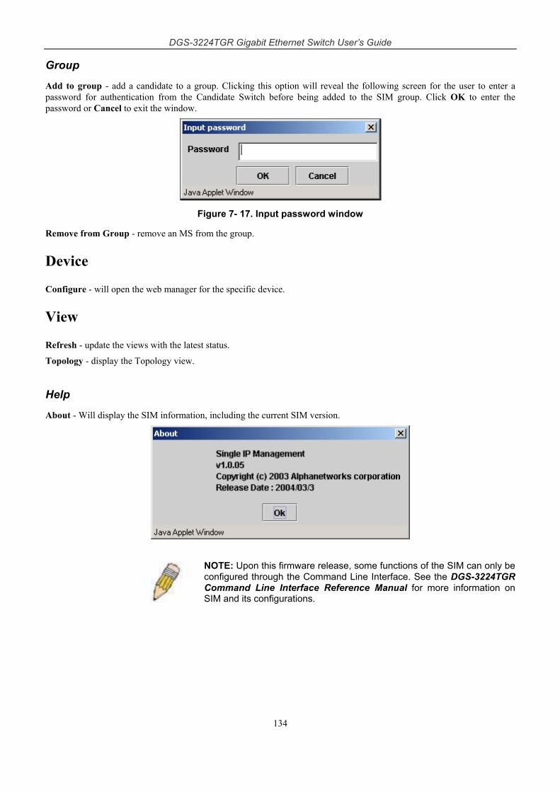
DGS-3224TGR Gigabit Ethernet Switch User’s Guide
134
Group
Add to group - add a candidate to a group. Clicking this option will reveal the following screen for the user to enter a password for authentication from the Candidate Switch before being added to the SIM group. Click OK to enter the password or Cancel to exit the window.
Figure 7- 17. Input password window
Remove from Group - remove an MS from the group.
Device
Configure - will open the web manager for the specific device.
View
Refresh - update the views with the latest status.
Topology - display the Topology view.
Help
About - Will display the SIM information, including the current SIM version.
NOTE: Upon this firmware release, some functions of the SIM can only be configured through the Command Line Interface. See the DGS-3224TGR Command Line Interface Reference Manual for more information on SIM and its configurations.
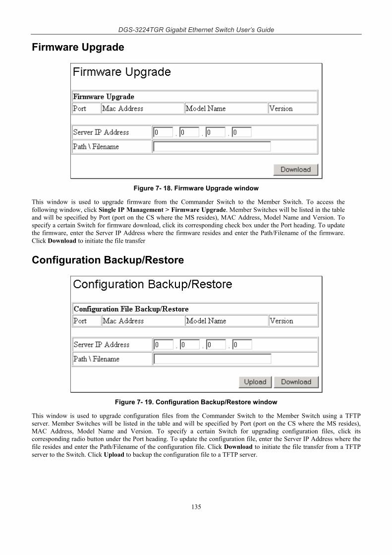
DGS-3224TGR Gigabit Ethernet Switch User’s Guide
135
Firmware Upgrade
Figure 7- 18. Firmware Upgrade window
This window is used to upgrade firmware from the Commander Switch to the Member Switch. To access the following window, click Single IP Management > Firmware Upgrade. Member Switches will be listed in the table and will be specified by Port (port on the CS where the MS resides), MAC Address, Model Name and Version. To specify a certain Switch for firmware download, click its corresponding check box under the Port heading. To update the firmware, enter the Server IP Address where the firmware resides and enter the Path/Filename of the firmware. Click Download to initiate the file transfer
Configuration Backup/Restore
Figure 7- 19. Configuration Backup/Restore window
This window is used to upgrade configuration files from the Commander Switch to the Member Switch using a TFTP server. Member Switches will be listed in the table and will be specified by Port (port on the CS where the MS resides), MAC Address, Model Name and Version. To specify a certain Switch for upgrading configuration files, click its corresponding radio button under the Port heading. To update the configuration file, enter the Server IP Address where the file resides and enter the Path/Filename of the configuration file. Click Download to initiate the file transfer from a TFTP server to the Switch. Click Upload to backup the configuration file to a TFTP server.
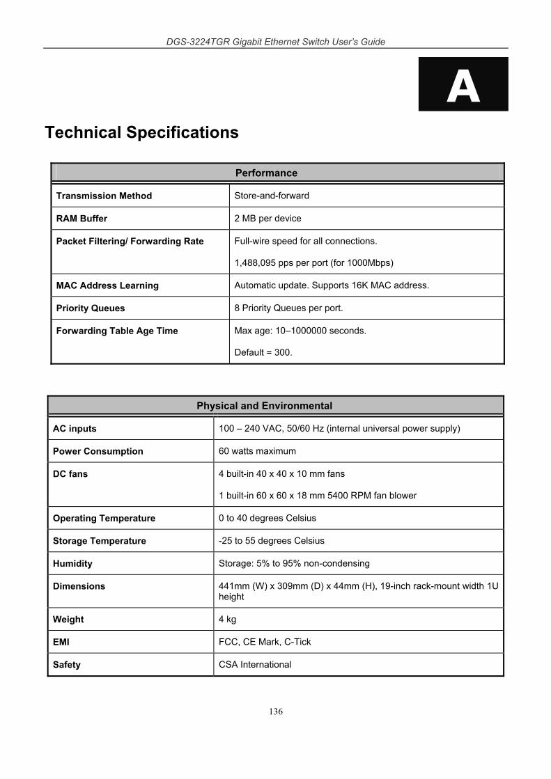
DGS-3224TGR Gigabit Ethernet Switch User’s Guide
136
A Technical Specifications
Performance
Transmission Method Store-and-forward
RAM Buffer 2 MB per device
Packet Filtering/ Forwarding Rate Full-wire speed for all connections.
1,488,095 pps per port (for 1000Mbps)
MAC Address Learning Automatic update. Supports 16K MAC address.
Priority Queues 8 Priority Queues per port.
Forwarding Table Age Time Max age: 10–1000000 seconds.
Default = 300.
Physical and Environmental
AC inputs 100 – 240 VAC, 50/60 Hz (internal universal power supply)
Power Consumption 60 watts maximum
DC fans 4 built-in 40 x 40 x 10 mm fans
1 built-in 60 x 60 x 18 mm 5400 RPM fan blower
Operating Temperature 0 to 40 degrees Celsius
Storage Temperature -25 to 55 degrees Celsius
Humidity Storage: 5% to 95% non-condensing
Dimensions 441mm (W) x 309mm (D) x 44mm (H), 19-inch rack-mount width 1U height
Weight 4 kg
EMI FCC, CE Mark, C-Tick
Safety CSA International
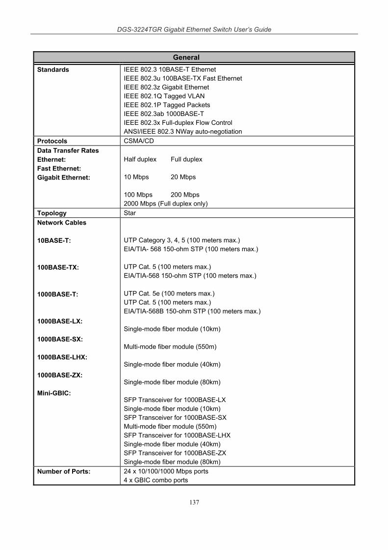
DGS-3224TGR Gigabit Ethernet Switch User’s Guide
137
General Standards IEEE 802.3 10BASE-T Ethernet
IEEE 802.3u 100BASE-TX Fast Ethernet IEEE 802.3z Gigabit Ethernet IEEE 802.1Q Tagged VLAN IEEE 802.1P Tagged Packets IEEE 802.3ab 1000BASE-T IEEE 802.3x Full-duplex Flow Control ANSI/IEEE 802.3 NWay auto-negotiation
Protocols CSMA/CD Data Transfer Rates Ethernet: Fast Ethernet: Gigabit Ethernet:
Half duplex Full duplex 10 Mbps 20 Mbps 100 Mbps 200 Mbps 2000 Mbps (Full duplex only)
Topology Star Network Cables 10BASE-T: 100BASE-TX: 1000BASE-T: 1000BASE-LX: 1000BASE-SX: 1000BASE-LHX: 1000BASE-ZX: Mini-GBIC:
UTP Category 3, 4, 5 (100 meters max.) EIA/TIA- 568 150-ohm STP (100 meters max.) UTP Cat. 5 (100 meters max.) EIA/TIA-568 150-ohm STP (100 meters max.) UTP Cat. 5e (100 meters max.) UTP Cat. 5 (100 meters max.) EIA/TIA-568B 150-ohm STP (100 meters max.) Single-mode fiber module (10km) Multi-mode fiber module (550m) Single-mode fiber module (40km) Single-mode fiber module (80km) SFP Transceiver for 1000BASE-LX Single-mode fiber module (10km) SFP Transceiver for 1000BASE-SX Multi-mode fiber module (550m) SFP Transceiver for 1000BASE-LHX Single-mode fiber module (40km) SFP Transceiver for 1000BASE-ZX Single-mode fiber module (80km)
Number of Ports: 24 x 10/100/1000 Mbps ports 4 x GBIC combo ports
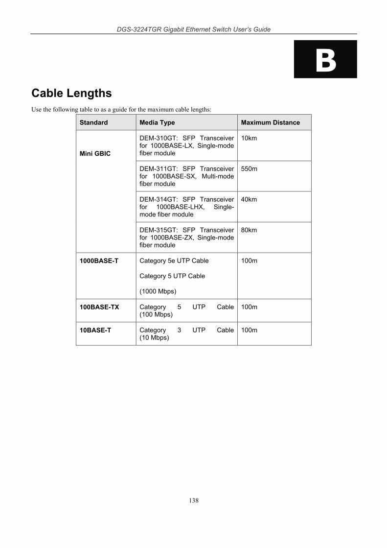
DGS-3224TGR Gigabit Ethernet Switch User’s Guide
138
B Cable Lengths Use the following table to as a guide for the maximum cable lengths:
Standard Media Type Maximum Distance
DEM-310GT: SFP Transceiver for 1000BASE-LX, Single-mode fiber module
10km
DEM-311GT: SFP Transceiver for 1000BASE-SX, Multi-mode fiber module
550m
DEM-314GT: SFP Transceiver for 1000BASE-LHX, Single-mode fiber module
40km
Mini GBIC
DEM-315GT: SFP Transceiver for 1000BASE-ZX, Single-mode fiber module
80km
1000BASE-T Category 5e UTP Cable
Category 5 UTP Cable
(1000 Mbps)
100m
100BASE-TX Category 5 UTP Cable (100 Mbps)
100m
10BASE-T Category 3 UTP Cable (10 Mbps)
100m
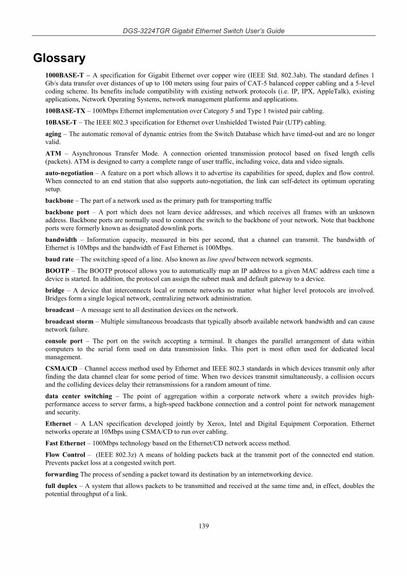
DGS-3224TGR Gigabit Ethernet Switch User’s Guide
139
Glossary 1000BASE-T – A specification for Gigabit Ethernet over copper wire (IEEE Std. 802.3ab). The standard defines 1 Gb/s data transfer over distances of up to 100 meters using four pairs of CAT-5 balanced copper cabling and a 5-level coding scheme. Its benefits include compatibility with existing network protocols (i.e. IP, IPX, AppleTalk), existing applications, Network Operating Systems, network management platforms and applications.
100BASE-TX – 100Mbps Ethernet implementation over Category 5 and Type 1 twisted pair cabling.
10BASE-T – The IEEE 802.3 specification for Ethernet over Unshielded Twisted Pair (UTP) cabling.
aging – The automatic removal of dynamic entries from the Switch Database which have timed-out and are no longer valid.
ATM – Asynchronous Transfer Mode. A connection oriented transmission protocol based on fixed length cells (packets). ATM is designed to carry a complete range of user traffic, including voice, data and video signals.
auto-negotiation – A feature on a port which allows it to advertise its capabilities for speed, duplex and flow control. When connected to an end station that also supports auto-negotiation, the link can self-detect its optimum operating setup.
backbone – The part of a network used as the primary path for transporting traffic
backbone port – A port which does not learn device addresses, and which receives all frames with an unknown address. Backbone ports are normally used to connect the switch to the backbone of your network. Note that backbone ports were formerly known as designated downlink ports.
bandwidth – Information capacity, measured in bits per second, that a channel can transmit. The bandwidth of Ethernet is 10Mbps and the bandwidth of Fast Ethernet is 100Mbps.
baud rate – The switching speed of a line. Also known as line speed between network segments.
BOOTP – The BOOTP protocol allows you to automatically map an IP address to a given MAC address each time a device is started. In addition, the protocol can assign the subnet mask and default gateway to a device.
bridge – A device that interconnects local or remote networks no matter what higher level protocols are involved. Bridges form a single logical network, centralizing network administration.
broadcast – A message sent to all destination devices on the network.
broadcast storm – Multiple simultaneous broadcasts that typically absorb available network bandwidth and can cause network failure.
console port – The port on the switch accepting a terminal. It changes the parallel arrangement of data within computers to the serial form used on data transmission links. This port is most often used for dedicated local management.
CSMA/CD – Channel access method used by Ethernet and IEEE 802.3 standards in which devices transmit only after finding the data channel clear for some period of time. When two devices transmit simultaneously, a collision occurs and the colliding devices delay their retransmissions for a random amount of time.
data center switching – The point of aggregation within a corporate network where a switch provides high-performance access to server farms, a high-speed backbone connection and a control point for network management and security.
Ethernet – A LAN specification developed jointly by Xerox, Intel and Digital Equipment Corporation. Ethernet networks operate at 10Mbps using CSMA/CD to run over cabling.
Fast Ethernet – 100Mbps technology based on the Ethernet/CD network access method.
Flow Control – (IEEE 802.3z) A means of holding packets back at the transmit port of the connected end station. Prevents packet loss at a congested switch port.
forwarding The process of sending a packet toward its destination by an internetworking device.
full duplex – A system that allows packets to be transmitted and received at the same time and, in effect, doubles the potential throughput of a link.

DGS-3224TGR Gigabit Ethernet Switch User’s Guide
140
GBIC – Gigabit interface converter, a transceiver that converts serial electric signals to serial optical signals and vice versa. In networking, a GBIC is used to interface a fiber optic system with an Ethernet system, such as Fibre Channel and Gigabit Ethernet.
A GBIC allows designers to design one type of device that can be adapted for either optical or copper applications. GBICs also are hot-swappable, which adds to the ease of upgrading electro-optical communication networks.
half duplex – A system that allows packets to be transmitted and received, but not at the same time. Contrasts with full duplex.
IP address – Internet Protocol address. A unique identifier for a device attached to a network using TCP/IP. The address is written as four octets separated with full-stops (periods), and is made up of a network section, an optional subnet section and a host section.
IPX – Internetwork Packet Exchange. A protocol allowing communication in a NetWare network.
LAN – Local Area Network. A network of connected computing resources (such as PCs, printers, servers) covering a relatively small geographic area (usually not larger than a floor or building). Characterized by high data rates and low error rates.
latency – The delay between the time a device receives a packet and the time the packet is forwarded out of the destination port.
line speed – See baud rate.
main port – The port in a resilient link that carries data traffic in normal operating conditions.
MDI – Medium Dependent Interface. An Ethernet port connection where the transmitter of one device is connected to the receiver of another device.
MDI-X – Medium Dependent Interface Cross-over. An Ethernet port connection where the internal transmit and receive lines are crossed.
MIB – Management Information Base. Stores a device’s management characteristics and parameters. MIBs are used by the Simple Network Management Protocol (SNMP) to contain attributes of their managed systems. The Switch contains its own internal MIB.
multicast – Single packets copied to a specific subset of network addresses. These addresses are specified in the destination-address field of the packet.
protocol – A set of rules for communication between devices on a network. The rules dictate format, timing, sequencing and error control.
resilient link – A pair of ports that can be configured so that one will take over data transmission should the other fail. See also main port and standby port.
RJ-45 – Standard 8-wire connectors for IEEE 802.3 10BASE-T networks.
RMON – Remote Monitoring. Subset of SNMP MIB II which allows monitoring and management capabilities by addressing up to ten different groups of information.
RPS – Redundant Power System. A device that provides a backup source of power when connected to the switch.
server farm – A cluster of servers in a centralized location serving a large user population.
SLIP – Serial Line Internet Protocol. A protocol which allows IP to run over a serial line connection.
SNMP – Simple Network Management Protocol. A protocol originally designed to be used in managing TCP/IP internets. SNMP is presently implemented on a wide range of computers and networking equipment and may be used to manage many aspects of network and end station operation.
Spanning Tree Protocol – (STP) A bridge-based system for providing fault tolerance on networks. STP works by allowing you to implement parallel paths for network traffic, and ensure that redundant paths are disabled when the main paths are operational and enabled if the main paths fail.
stack – A group of network devices that are integrated to form a single logical device.
standby port – The port in a resilient link that will take over data transmission if the main port in the link fails.
switch – A device which filters, forwards and floods packets based on the packet’s destination address. The switch learns the addresses associated with each switch port and builds tables based on this information to be used for the switching decision.

DGS-3224TGR Gigabit Ethernet Switch User’s Guide
141
TCP/IP – A layered set of communications protocols providing Telnet terminal emulation, FTP file transfer, and other services for communication among a wide range of computer equipment.
Telnet – A TCP/IP application protocol that provides virtual terminal service, letting a user log in to another computer system and access a host as if the user were connected directly to the host.
TFTP – Trivial File Transfer Protocol. Allows you to transfer files (such as software upgrades) from a remote device using your switch’s local management capabilities.
UDP – User Datagram Protocol. An Internet standard protocol that allows an application program on one device to send a datagram to an application program on another device.
VLAN – Virtual LAN. A group of location- and topology-independent devices that communicate as if they are on a common physical LAN.
VLT – Virtual LAN Trunk. A Switch-to-Switch link which carries traffic for all the VLANs on each Switch.
VT100 – A type of terminal that uses ASCII characters. VT100 screens have a text-based appearance.

DGS-3224TGR Gigabit Ethernet Switch User’s Guide
142
Warranty and Registration Information (All countries and regions excluding USA) Wichtige Sicherheitshinweise 1. Bitte lesen Sie sich diese Hinweise sorgfältig durch.
2. Heben Sie diese Anleitung für den spätern Gebrauch auf.
3. Vor jedem Reinigen ist das Gerät vom Stromnetz zu trennen. Vervenden Sie keine Flüssig- oder Aerosolreiniger. Am besten dient ein angefeuchtetes Tuch zur Reinigung.
4. Um eine Beschädigung des Gerätes zu vermeiden sollten Sie nur Zubehörteile verwenden, die vom Hersteller zugelassen sind.
5. Das Gerät is vor Feuchtigkeit zu schützen.
6. Bei der Aufstellung des Gerätes ist auf sichern Stand zu achten. Ein Kippen oder Fallen könnte Verletzungen hervorrufen. Verwenden Sie nur sichere Standorte und beachten Sie die Aufstellhinweise des Herstellers.
7. Die Belüftungsöffnungen dienen zur Luftzirkulation die das Gerät vor Überhitzung schützt. Sorgen Sie dafür, daß diese Öffnungen nicht abgedeckt werden.
8. Beachten Sie beim Anschluß an das Stromnetz die Anschlußwerte.
9. Die Netzanschlußsteckdose muß aus Gründen der elektrischen Sicherheit einen Schutzleiterkontakt haben.
10. Verlegen Sie die Netzanschlußleitung so, daß niemand darüber fallen kann. Es sollete auch nichts auf der Leitung abgestellt werden.
11. Alle Hinweise und Warnungen die sich am Geräten befinden sind zu beachten.
12. Wird das Gerät über einen längeren Zeitraum nicht benutzt, sollten Sie es vom Stromnetz trennen. Somit wird im Falle einer Überspannung eine Beschädigung vermieden.
13. Durch die Lüftungsöffnungen dürfen niemals Gegenstände oder Flüssigkeiten in das Gerät gelangen. Dies könnte einen Brand bzw. Elektrischen Schlag auslösen.
14. Öffnen Sie niemals das Gerät. Das Gerät darf aus Gründen der elektrischen Sicherheit nur von authorisiertem Servicepersonal geöffnet werden.
15. Wenn folgende Situationen auftreten ist das Gerät vom Stromnetz zu trennen und von einer qualifizierten Servicestelle zu überprüfen:
a. Netzkabel oder Netzstecker sint beschädigt.
b. Flüssigkeit ist in das Gerät eingedrungen.
c. Das Gerät war Feuchtigkeit ausgesetzt.
d. Wenn das Gerät nicht der Bedienungsanleitung ensprechend funktioniert oder Sie mit Hilfe dieser Anleitung keine Verbesserung erzielen.
e. Das Gerät ist gefallen und/oder das Gehäuse ist beschädigt.
f. Wenn das Gerät deutliche Anzeichen eines Defektes aufweist.
16. Bei Reparaturen dürfen nur Orginalersatzteile bzw. den Orginalteilen entsprechende Teile verwendet werden. Der Einsatz von ungeeigneten Ersatzteilen kann eine weitere Beschädigung hervorrufen.
17. Wenden Sie sich mit allen Fragen die Service und Repartur betreffen an Ihren Servicepartner. Somit stellen Sie die Betriebssicherheit des Gerätes sicher.
18. Zum Netzanschluß dieses Gerätes ist eine geprüfte Leitung zu verwenden, Für einen Nennstrom bis 6A und einem Gerätegewicht grőßer 3kg ist eine Leitung nicht leichter als H05VV-F, 3G, 0.75mm2 einzusetzen.
WARRANTIES EXCLUSIVE IF THE D-LINK PRODUCT DOES NOT OPERATE AS WARRANTED ABOVE, THE CUSTOMER'S SOLE REMEDY SHALL BE, AT D-LINK'S OPTION, REPAIR OR REPLACEMENT. THE FOREGOING WARRANTIES AND REMEDIES ARE EXCLUSIVE AND ARE IN LIEU OF ALL OTHER WARRANTIES, EXPRESSED OR IMPLIED, EITHER IN FACT OR BY OPERATION OF LAW, STATUTORY OR OTHERWISE, INCLUDING WARRANTIES OF MERCHANTABILITY AND FITNESS FOR A PARTICULAR PURPOSE. D-LINK NEITHER ASSUMES NOR AUTHORIZES ANY OTHER PERSON TO ASSUME FOR IT ANY OTHER LIABILITY IN CONNECTION WITH THE SALE, INSTALLATION MAINTENANCE OR USE OF D-LINK'S PRODUCTS.
D-LINK SHALL NOT BE LIABLE UNDER THIS WARRANTY IF ITS TESTING AND EXAMINATION DISCLOSE THAT THE ALLEGED DEFECT IN THE PRODUCT DOES NOT EXIST OR WAS CAUSED BY THE CUSTOMER'S OR ANY THIRD PERSON'S MISUSE, NEGLECT, IMPROPER INSTALLATION OR TESTING, UNAUTHORIZED ATTEMPTS TO REPAIR, OR ANY OTHER CAUSE BEYOND THE RANGE OF THE INTENDED USE, OR BY ACCIDENT, FIRE, LIGHTNING OR OTHER HAZARD.
LIMITATION OF LIABILITY IN NO EVENT WILL D-LINK BE LIABLE FOR ANY DAMAGES, INCLUDING LOSS OF DATA, LOSS OF PROFITS, COST OF COVER OR OTHER INCIDENTAL, CONSEQUENTIAL OR INDIRECT DAMAGES ARISING OUT THE INSTALLATION, MAINTENANCE, USE, PERFORMANCE,
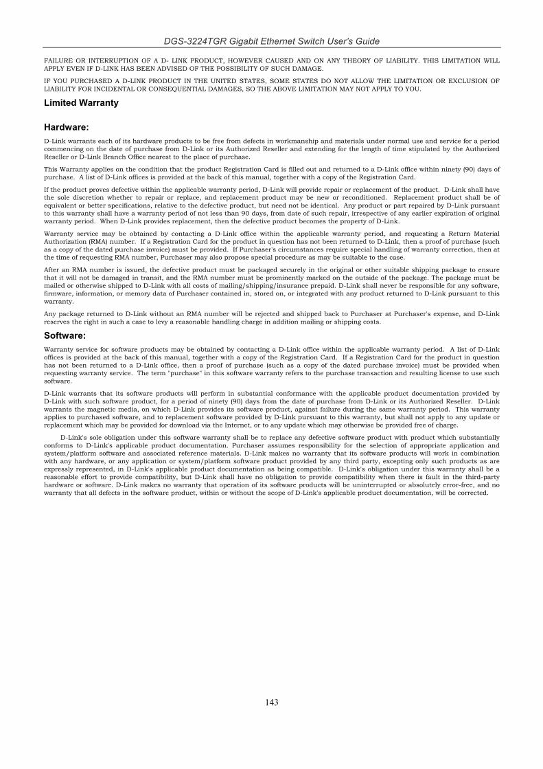
DGS-3224TGR Gigabit Ethernet Switch User’s Guide
143
FAILURE OR INTERRUPTION OF A D- LINK PRODUCT, HOWEVER CAUSED AND ON ANY THEORY OF LIABILITY. THIS LIMITATION WILL APPLY EVEN IF D-LINK HAS BEEN ADVISED OF THE POSSIBILITY OF SUCH DAMAGE.
IF YOU PURCHASED A D-LINK PRODUCT IN THE UNITED STATES, SOME STATES DO NOT ALLOW THE LIMITATION OR EXCLUSION OF LIABILITY FOR INCIDENTAL OR CONSEQUENTIAL DAMAGES, SO THE ABOVE LIMITATION MAY NOT APPLY TO YOU.
Limited Warranty
Hardware: D-Link warrants each of its hardware products to be free from defects in workmanship and materials under normal use and service for a period commencing on the date of purchase from D-Link or its Authorized Reseller and extending for the length of time stipulated by the Authorized Reseller or D-Link Branch Office nearest to the place of purchase. This Warranty applies on the condition that the product Registration Card is filled out and returned to a D-Link office within ninety (90) days of purchase. A list of D-Link offices is provided at the back of this manual, together with a copy of the Registration Card.
If the product proves defective within the applicable warranty period, D-Link will provide repair or replacement of the product. D-Link shall have the sole discretion whether to repair or replace, and replacement product may be new or reconditioned. Replacement product shall be of equivalent or better specifications, relative to the defective product, but need not be identical. Any product or part repaired by D-Link pursuant to this warranty shall have a warranty period of not less than 90 days, from date of such repair, irrespective of any earlier expiration of original warranty period. When D-Link provides replacement, then the defective product becomes the property of D-Link.
Warranty service may be obtained by contacting a D-Link office within the applicable warranty period, and requesting a Return Material Authorization (RMA) number. If a Registration Card for the product in question has not been returned to D-Link, then a proof of purchase (such as a copy of the dated purchase invoice) must be provided. If Purchaser's circumstances require special handling of warranty correction, then at the time of requesting RMA number, Purchaser may also propose special procedure as may be suitable to the case.
After an RMA number is issued, the defective product must be packaged securely in the original or other suitable shipping package to ensure that it will not be damaged in transit, and the RMA number must be prominently marked on the outside of the package. The package must be mailed or otherwise shipped to D-Link with all costs of mailing/shipping/insurance prepaid. D-Link shall never be responsible for any software, firmware, information, or memory data of Purchaser contained in, stored on, or integrated with any product returned to D-Link pursuant to this warranty.
Any package returned to D-Link without an RMA number will be rejected and shipped back to Purchaser at Purchaser's expense, and D-Link reserves the right in such a case to levy a reasonable handling charge in addition mailing or shipping costs.
Software: Warranty service for software products may be obtained by contacting a D-Link office within the applicable warranty period. A list of D-Link offices is provided at the back of this manual, together with a copy of the Registration Card. If a Registration Card for the product in question has not been returned to a D-Link office, then a proof of purchase (such as a copy of the dated purchase invoice) must be provided when requesting warranty service. The term "purchase" in this software warranty refers to the purchase transaction and resulting license to use such software.
D-Link warrants that its software products will perform in substantial conformance with the applicable product documentation provided by D-Link with such software product, for a period of ninety (90) days from the date of purchase from D-Link or its Authorized Reseller. D-Link warrants the magnetic media, on which D-Link provides its software product, against failure during the same warranty period. This warranty applies to purchased software, and to replacement software provided by D-Link pursuant to this warranty, but shall not apply to any update or replacement which may be provided for download via the Internet, or to any update which may otherwise be provided free of charge.
D-Link's sole obligation under this software warranty shall be to replace any defective software product with product which substantially conforms to D-Link's applicable product documentation. Purchaser assumes responsibility for the selection of appropriate application and system/platform software and associated reference materials. D-Link makes no warranty that its software products will work in combination with any hardware, or any application or system/platform software product provided by any third party, excepting only such products as are expressly represented, in D-Link's applicable product documentation as being compatible. D-Link's obligation under this warranty shall be a reasonable effort to provide compatibility, but D-Link shall have no obligation to provide compatibility when there is fault in the third-party hardware or software. D-Link makes no warranty that operation of its software products will be uninterrupted or absolutely error-free, and no warranty that all defects in the software product, within or without the scope of D-Link's applicable product documentation, will be corrected.

S ubject to the terms and conditions set forth herein, D-Link Systems, Inc. (“D-Link”) provides this Limited Warranty: • Only to the person or entity that originally purchased the product from D-Link or its authorized reseller or distributor, and • Only for products purchased and delivered within the fifty states of the United States, the District of Columbia, U.S. Possessions or Protectorates, U.S.
Military Installations, or addresses with an APO or FPO. Limited Warranty: D-Link warrants that the hardware portion of the D-Link product described below (“Hardware”) will be free from material defects in workmanship and materials under normal use from the date of original retail purchase of the product, for the period set forth below (“Warranty Period”), except s otherwise stated herein. a
L imited Lifetime Warranty for the product is defined as follows:
• Hardware: For as long as the original customer/end user owns the product, or five (5) years after product discontinuance, whichever occurs first (excluding power supplies and fans)
• Power supplies and fans: Three (3) Year • Spare parts and spare kits: Ninety (90) days The customer's sole and exclusive remedy and the entire liability of D-Link and its suppliers under this Limited Warranty will be, at D-Link’s option, to repair or replace the defective Hardware during the Warranty Period at no charge to the original owner or to refund the actual purchase price paid. Any repair or replacement will be rendered by D-Link at an Authorized D-Link Service Office. The replacement hardware need not be new or have an identical make, model or part. D-Link may, at its option, replace the defective Hardware or any part thereof with any reconditioned product that D-Link reasonably determines is substantially equivalent (or superior) in all material respects to the defective Hardware. Repaired or replacement hardware will be warranted for the remainder of the original Warranty Period or ninety (90) days, whichever is longer, and is subject to the same limitations and exclusions. If a material defect is incapable of correction, or if D-Link determines that it is not practical to repair or replace the defective Hardware, the actual price paid by the original purchaser for the defective Hardware will be refunded by D-Link upon return to D-Link of the defective Hardware. All Hardware or part thereof that is replaced by D-Link, or for
hich the purchase price is refunded, shall become the property of D-Link upon replacement or refund. w Limited Software Warranty: D-Link warrants that the software portion of the product (“Software”) will substantially conform to D-Link’s then current functional specifications for the Software, as set forth in the applicable documentation, from the date of original retail purchase of the Software for a period of ninety (90) days (“Software Warranty Period”), provided that the Software is properly installed on approved hardware and operated as contemplated in its documentation. D-Link further warrants that, during the Software Warranty Period, the magnetic media on which D-Link delivers the Software will be free of physical defects. The customer's sole and exclusive remedy and the entire liability of D-Link and its suppliers under this Limited Warranty will be, at D-Link’s option, to replace the non-conforming Software (or defective media) with software that substantially conforms to D-Link’s functional specifications for the Software or to refund the portion of the actual purchase price paid that is attributable to the Software. Except as otherwise agreed by D-Link in writing, the replacement Software is provided only to the original licensee, and is subject to the terms and conditions of the license granted by D-Link for the Software. Replacement Software will be warranted for the remainder of the original Warranty Period and is subject to the same limitations and exclusions. If a material non-conformance is incapable of correction, or if D-Link determines in its sole discretion that it is not practical to replace the non-conforming Software, the price paid by the original licensee for the non-conforming Software will be refunded by D-Link; provided that the non-conforming Software (and all copies thereof) is first returned to D-ink. The license granted respecting any Software for which a refund is given automatically terminates. L
Non-Applicability of Warranty: The Limited Warranty provided hereunder for Hardware and Software portions of D-Link's products will not be applied to and does not cover any refurbished product and any product purchased through the inventory clearance or liquidation sale or other sales in which D-Link, the sellers, or the liquidators expressly disclaim their warranty obligation pertaining to the product and in that case, the product is being sold "As-Is" without any warranty whatsoever including, without limitation, the Limited Warranty as described herein, notwithstanding anything stated herein to the contrary. Submitting A Claim: The customer shall return the product to the original purchase point based on its return policy. In case the return policy period has expired and the product is within warranty, the customer shall submit a claim to D-Link as outlined below: • The customer must submit with the product as part of the claim a written description of the Hardware defect or Software nonconformance in sufficient
detail to allow D-Link to confirm the same, along with proof of purchase of the product (such as a copy of the dated purchase invoice for the product) if the product is not registered.
• The customer must obtain a Case ID Number from D-Link Technical Support at 1-877-453-5465, who will attempt to assist the customer in resolving any suspected defects with the product. If the product is considered defective, the customer must obtain a Return Material Authorization (“RMA”) number by completing the RMA form and entering the assigned Case ID Number at https://rma.dlink.com/.
• After an RMA number is issued, the defective product must be packaged securely in the original or other suitable shipping package to ensure that it will not be damaged in transit, and the RMA number must be prominently marked on the outside of the package. Do not include any manuals or accessories in the shipping package. D-Link will only replace the defective portion of the product and will not ship back any accessories.
• The customer is responsible for all in-bound shipping charges to D-Link. No Cash on Delivery (“COD”) is allowed. Products sent COD will either be rejected by D-Link or become the property of D-Link. Products shall be fully insured by the customer and shipped to D-Link Systems, Inc., 17595 Mt. Herrmann, Fountain Valley, CA 92708. D-Link will not be held responsible for any packages that are lost in transit to D-Link. The repaired or replaced packages will be shipped to the customer via UPS Ground or any common carrier selected by D-Link. Return shipping charges shall be prepaid by D-Link if you use an address in the United States, otherwise we will ship the product to you freight collect. Expedited shipping is available upon request and provided shipping charges are prepaid by the customer.
D-Link may reject or return any product that is not packaged and shipped in strict compliance with the foregoing requirements, or for which an RMA number is not visible from the outside of the package. The product owner agrees to pay D-Link’s reasonable handling and return shipping charges for any product that is ot packaged and shipped in accordance with the foregoing requirements, or that is determined by D-Link not to be defective or non-conforming. n
What Is Not Covered: The Limited Warranty provided herein by D-Link does not cover: Products that, in D-Link’s judgment, have been subjected to abuse, accident, alteration, modification, tampering, negligence, misuse, faulty installation, lack of reasonable care, repair or service in any way that is not contemplated in the documentation for the product, or if the model or serial number has been altered, tampered with, defaced or removed; Initial installation, installation and removal of the product for repair, and shipping costs; Operational adjustments covered in the operating manual for the product, and normal maintenance; Damage that occurs in shipment, due to act of God, failures due to power surge, and cosmetic damage; Any hardware, software, firmware or other products or services provided by anyone other than D-Link; and Products that have been purchased from inventory clearance or liquidation sales or other sales in which D-Link, the sellers, or the liquidators expressly disclaim their warranty obligation pertaining to the product. While necessary maintenance or repairs on your Product can be performed by any company, we recommend that you use only an Authorized D-Link Service Office. Improper or incorrectly erformed maintenance or repair voids this Limited Warranty. p
Disclaimer of Other Warranties: EXCEPT FOR THE LIMITED WARRANTY SPECIFIED HEREIN, THE PRODUCT IS PROVIDED “AS-IS” WITHOUT ANY WARRANTY OF ANY KIND WHATSOEVER INCLUDING, WITHOUT LIMITATION, ANY WARRANTY OF MERCHANTABILITY, FITNESS FOR A PARTICULAR PURPOSE AND NON-INFRINGEMENT. IF ANY IMPLIED WARRANTY CANNOT BE DISCLAIMED IN ANY TERRITORY WHERE A PRODUCT IS SOLD, THE DURATION OF SUCH IMPLIED WARRANTY SHALL BE LIMITED TO NINETY (90) DAYS. EXCEPT AS EXPRESSLY COVERED

UNDER THE LIMITED WARRANTY PROVIDED HEREIN, THE ENTIRE RISK AS TO THE QUALITY, SELECTION AND PERFORMANCE OF THE RODUCT IS WITH THE PURCHASER OF THE PRODUCT. P
Limitation of Liability: TO THE MAXIMUM EXTENT PERMITTED BY LAW, D-LINK IS NOT LIABLE UNDER ANY CONTRACT, NEGLIGENCE, STRICT LIABILITY OR OTHER LEGAL OR EQUITABLE THEORY FOR ANY LOSS OF USE OF THE PRODUCT, INCONVENIENCE OR DAMAGES OF ANY CHARACTER, WHETHER DIRECT, SPECIAL, INCIDENTAL OR CONSEQUENTIAL (INCLUDING, BUT NOT LIMITED TO, DAMAGES FOR LOSS OF GOODWILL, LOSS OF REVENUE OR PROFIT, WORK STOPPAGE, COMPUTER FAILURE OR MALFUNCTION, FAILURE OF OTHER EQUIPMENT OR COMPUTER PROGRAMS TO WHICH D-LINK’S PRODUCT IS CONNECTED WITH, LOSS OF INFORMATION OR DATA CONTAINED IN, STORED ON, OR INTEGRATED WITH ANY PRODUCT RETURNED TO D-LINK FOR WARRANTY SERVICE) RESULTING FROM THE USE OF THE PRODUCT, RELATING TO WARRANTY SERVICE, OR ARISING OUT OF ANY BREACH OF THIS LIMITED WARRANTY, EVEN IF D-LINK HAS BEEN ADVISED OF THE POSSIBILITY OF SUCH DAMAGES. THE SOLE REMEDY FOR A BREACH OF THE FOREGOING LIMITED WARRANTY IS REPAIR, REPLACEMENT OR REFUND OF THE DEFECTIVE OR NON-CONFORMING PRODUCT. THE MAXIMUM LIABILITY OF D-LINK UNDER THIS WARRANTY IS LIMITED TO THE PURCHASE PRICE OF THE PRODUCT COVERED BY THE WARRANTY. THE FOREGOING EXPRESS WRITTEN WARRANTIES AND REMEDIES
RE EXCLUSIVE AND ARE IN LIEU OF ANY OTHER WARRANTIES OR REMEDIES, EXPRESS, IMPLIED OR STATUTORY. Limitation of Liability: TO THE MAXIMUM EXTENT PERMITTED BY LAW, D-LINK IS NOT LIABLE UNDER ANY CONTRACT, NEGLIGENCE, STRICT LIABILITY OR OTHER LEGAL OR EQUITABLE THEORY FOR ANY LOSS OF USE OF THE PRODUCT, INCONVENIENCE OR DAMAGES OF ANY CHARACTER, WHETHER DIRECT, SPECIAL, INCIDENTAL OR CONSEQUENTIAL (INCLUDING, BUT NOT LIMITED TO, DAMAGES FOR LOSS OF GOODWILL, LOSS OF REVENUE OR PROFIT, WORK STOPPAGE, COMPUTER FAILURE OR MALFUNCTION, FAILURE OF OTHER EQUIPMENT OR COMPUTER PROGRAMS TO WHICH D-LINK’S PRODUCT IS CONNECTED WITH, LOSS OF INFORMATION OR DATA CONTAINED IN, STORED ON, OR INTEGRATED WITH ANY PRODUCT RETURNED TO D-LINK FOR WARRANTY SERVICE) RESULTING FROM THE USE OF THE PRODUCT, RELATING TO WARRANTY SERVICE, OR ARISING OUT OF ANY BREACH OF THIS LIMITED WARRANTY, EVEN IF D-LINK HAS BEEN ADVISED OF THE POSSIBILITY OF SUCH DAMAGES. THE SOLE REMEDY FOR A BREACH OF THE FOREGOING LIMITED WARRANTY IS REPAIR, REPLACEMENT OR REFUND OF THE DEFECTIVE OR NON-CONFORMING PRODUCT. THE MAXIMUM LIABILITY OF D-LINK UNDER THIS WARRANTY IS LIMITED TO THE PURCHASE PRICE OF THE PRODUCT COVERED BY THE WARRANTY. THE FOREGOING EXPRESS WRITTEN WARRANTIES AND REMEDIES
RE EXCLUSIVE AND ARE IN LIEU OF ANY OTHER WARRANTIES OR REMEDIES, EXPRESS, IMPLIED OR STATUTORY. A Governing Law: This Limited Warranty shall be governed by the laws of the State of California. Some states do not allow exclusion or limitation of incidental or consequential damages, or limitations on how long an implied warranty lasts, so the foregoing limitations and exclusions may not apply. This Limited Warranty provides specific legal rights and you may also have other rights which vary from state to state. Trademarks: D-Link is a registered trademark of D-Link Systems, Inc. Other trademarks or registered trademarks are the property of their respective owners. Copyright Statement: No part of this publication or documentation accompanying this product may be reproduced in any form or by any means or used to make any derivative such as translation, transformation, or adaptation without permission from D-Link Corporation/D-Link Systems, Inc., as stipulated by the United States Copyright Act of 1976 and any amendments thereto. Contents are subject to change without prior notice. Copyright 2004 by D-Link Corporation/D-Link Systems, Inc. All rights reserved. CE Mark Warning: This is a Class A product. In a residential environment, this product may cause radio interference, in which case the user may be required to take adequate measures. FCC Statement: This equipment has been tested and found to comply with the limits for a Class A digital device, pursuant to part 15 of the FCC Rules. These limits are designed to provide reasonable protection against harmful interference in a commercial installation. This equipment generates, uses, and can radiate radio frequency energy and, if not installed and used in accordance with the instructions, may cause harmful interference to radio communication. However, there is no guarantee that interference will not occur in a particular installation. Operation of this equipment in a residential environment is likely to cause harmful interference to radio or television reception. If this equipment does cause harmful interference to radio or television reception, which can be determined by turning the equipment off and on, the user is encouraged to try to correct the interference by one or more of the following measures: • Reorient or relocate the receiving antenna. • Increase the separation between the equipment and receiver. • Connect the equipment into an outlet on a circuit different from that to which the receiver is connected. • Consult the dealer or an experienced radio/TV technician for help. For detailed warranty information applicable to products purchased outside the United States, please contact the corresponding local D-Link office.

Product Registration
Register online your D-Link product at http://support.dlink.com/register/ Product registration is entirely voluntary and failure to complete or return this form will not diminish your warranty rights.
Registration Card (All countries and regions excluding USA)
Print, type or use block letters. Your name: Mr./Ms _____________________________________________________________________________ Organization: ________________________________________________ Dept. ____________________________ Your title at organization: ________________________________________________________________________ Telephone: _______________________________________ Fax:________________________________________ Organization's full address: ______________________________________________________________________ ____________________________________________________________________________________________ Country: _____________________________________________________________________________________ Date of purchase (Month/Day/Year): _______________________________________________________________
Product Model Product Serial No.
* Product installed in type of
computer (e.g., Compaq 486)
* Product installed in
computer serial No.
(* Applies to adapters only)
Product was purchased from:85 Reseller's name: ______________________________________________________________________________ Telephone: _______________________________________ Fax:________________________________________ Reseller's full address: _________________________________________________________________________ _________________________________________________________________________ _________________________________________________________________________
Answers to the following questions help us to support your product: 1. Where and how will the product primarily be used? oHome oOffice oTravel oCompany Business oHome Business oPersonal Use
2. How many employees work at installation site? o1 employee o2-9 o10-49 o50-99 o100-499 o500-999 o1000 or more
3. What network protocol(s) does your organization use ? oXNS/IPX oTCP/IP oDECnet oOthers_____________________________
4. What network operating system(s) does your organization use ? oD-Link LANsmart oNovell NetWare oNetWare Lite oSCO Unix/Xenix oPC NFS o3Com 3+Open oBanyan Vines oDECnet Pathwork oWindows NT oWindows NTAS oWindows '95 oOthers__________________________________________
5. What network management program does your organization use ? oD-View oHP OpenView/Windows oHP OpenView/Unix oSunNet Manager oNovell NMS oNetView 6000 oOthers________________________________________
6. What network medium/media does your organization use ? oFiber-optics oThick coax Ethernet oThin coax Ethernet o10BASE-T UTP/STP o100BASE-TX o100BASE-T4 o100VGAnyLAN oOthers_________________
7. What applications are used on your network? oDesktop publishing oSpreadsheet oWord processing oCAD/CAM oDatabase management oAccounting oOthers_____________________
8. What category best describes your company? oAerospace oEngineering oEducation oFinance oHospital oLegal oInsurance/Real Estate oManufacturing oRetail/Chainstore/Wholesale oGovernment oTransportation/Utilities/Communication oVAR oSystem house/company oOther________________________________
9. Would you recommend your D-Link product to a friend? oYes oNo oDon't know yet
10.Your comments on this product? _______________________________________________________________________________________