Embed Size (px)
Citation preview

D
Dinacell Electrónnica s.l.
W
Loafor
We
ad C Indu
eig
Celustr
hin
lls ial
ng
Made in
Spain

pro
ind
ind
co
we
loa
co
Th
wo
ve
se
Di
co
co
rai
co
po
att
ma
1
Since 19
ojects in the
dustrial sect
dustrial weig
oncept of ou
eighing syst
ad cells as w
ontrollers.
he company
orld-wide di
ery competit
everal count
nacell coun
ontribute wit
ontinued imp
ise it to the
During th
onfidence by
ost sales se
tended.
This qual
aterials and
94 Dinacell
e field of the
tors, such a
ghing and h
ur work invo
tem, includi
well as the
y, located in
stribution of
tive prices a
tries all arou
nts on qualif
th their large
provement a
top, workin
hese years t
y the good q
rvice where
lity is guara
d the profes
introductio
production
Electrónica
e load cells
as cranes, a
handling, sil
olves the wh
ng the desi
electronic d
n Madrid (Sp
ffering its h
and a specia
und the wor
fied and com
e experienc
and develop
ng hard day
the compan
quality of th
e our custom
anteed by th
sionalism o
on of new te
n line
a has devel
with applic
automotive
los and elev
hole process
gn and man
devices suc
pain), has in
igh quality p
al customer
rld.
mpetent peo
ce, around 2
pment of th
by day.
ny has won
he products
mers are alw
he exclusive
of our staff, a
echnologies
oped sever
ations in dif
industry,
vators. The
s of a load
nufacturing
ch as display
n present d
products wi
r service to
ople who
20 years, to
e company
its clients
and an effe
ways friend
e selection o
as well as t
s in the
ral
fferent
of the
ys and
ay a
th
o the
y to
ective
ly
of the
he

2
Index
Aplication Model Page. (kg) (t.)
1 15
25
50
100
150
200
500
1 1.5
3 5 10
20
40
60
Flexion
CF 3
CFA 4
CFD 5
CFRT 6 MP 7 MP150 8
Compression
BP 9
BP2093 10
SK 11
Traction
CT 12
CTDC 13
CTG 14
CTR 15
TLCX 16
Traction / Compression CTC 17
CTCM 18
Limiter on Ropes
LCA2 19
LM 20
LMK 21
LMS 22
Torque Sensor
PAR500 23 PAR75 -1200 24
Load Pin
BLP 25 STA 26
Crosshead /Beam Sensor
SD1000 27 SV3000 28
Control Unit
ADS420 29 INS2r 30 MR 31 MR1 32 MLS1R 33 VMA10 34 Sums Box 35

3
Load cell flexion 5084
CFWORK DRIVE
TRACTION WORK
Load cells specially designed to work in jutting out with shear or flexion sensor element
Equipped with insulating cases of high mechanical resistance
Dimensions in mm
Wiring diagram
Technical Characteristics
Nominal load (nL) 15 – 30 – 50 – 75 – 100 – 150 – 200 – 250 – 300 – 500 – 750 – 1000 ‐ 1500 kg.
Minimum insulation resistance (V.Test = 100V) 4 GΩ
Input impedance 380Ω ± 10 Ω
Sensibility 2,0 mV/V ± 0,1 % Output impedance 350Ω ± 1.5 Ω
Zero Balance 2% F.S. Creep (over 30 minutes) 0.03 % F.S.
Maximum excitation voltage 12V. Load Limit Without Loss of Characteristics 150 % F.S.
Hysteresis error 0,033 % F.S. Minimun breaking load 250% F.S.
Maximum linerity error 0,02 % F.S. Protection class IP 67
Compensated temperature range ‐10 ... 40 ºC Cable type 4x0,22 mm2 Ø6
Service temperature range ‐20 ... 60 ºC Cable length 4 m.
Storage temperature range ‐20 ... 70 ºC Material
Aluminum < 50 kg.
Alloy steel 50 kg. Temperature effect on sensitivity 0,022 % F.S.
Surface treatment Chemical nickel (Only Alloy steel) Temperature effect on zero 0,018 % / 5ºC

4
5085 Load cell flexion
CFA
Load cells specially designed to work in jutting out, with flexion or shear element
Equipped with insulating cases of high mechanical resistance
nL (t) 1 – 2 – 3 - 5 7,5 - 10 15 - 20
A 200 275 280
B 46 58 65
C 46 58 65
D 38 48 55
ØE 19 25 29
ØF 23 25 29
ØG 19 - -
H 20 25 30
J 60 80 80
K 100 140 140
L 104 140 140
Dimensions in mm
Wiring diagram
Technical Characteristics
Nominal load (nL) 1 ‐2 – 3 – 5 – 7,5 – 10 – 15 ‐ 20t Maximum excitation voltage 12V
Sensibility 2 mV/V ± 0,1% Insulation Resistance (V. Test = 100V) 4 GΩ
Zero Balance 1,5 % F.S. Input impedance 380 Ω ±10 Ω
Non linearity 0,019 % F.S. Output impedance 350 Ω ±1.5 Ω
Hysteresis error 0,020 % F.S. Load Limit Without Loss of Characteristics 150 % F.S.
Creep (over 30 minutes) 0,017 % F.S. Minimun breaking load 300 % F.S.
Temperature effect on sensitivity 0,023 % F.S. Cable type 4x0,22 mm2 Ø6
Temperature effect on zero 0,013 % / 5ºC Cable length 4 m
Compensated temperature range ‐10 ... 40 ºC Protection class IP 67
Service temperature range ‐20 ... 60 ºC Material Alloy steel
Storage temperature range ‐20 ... 70 ºC Surface treatment Chemical nickel

5
Load cell flexion 6490
CFD
Nominal load (nL) t
0,5 – 1 – 1,5 2 - 3
A 24 34
B Ø34 Ø45
C M‐10 M‐16
D Ø13 Ø16.5
E 48 58
Load cells specially designed to work in jutting out, with flexion or shear element
Optional accesories
Dimensions in mm
Wiring diagram
Technical Characteristics
Nominal load (nL) 0.5 – 1 – 1,5 – 2 ‐ 3t Minimum insulation resistance (V.Test = 100V) 4 GΩ
Sensibility 2,0 mV/V ± 0,1 % Input impedance 380 ± 10 Ω
Zero Balance 2% F.S. Output impedance 350 ± 1.5 Ω
Maximum excitation voltage 12V. Creep (over 30 minutes) 0,03 % F.S.
Hysteresis error 0,028 % F.S. Load Limit Without Loss of Characteristics 120 % F.S.
Maximum linerity error 0,026 % F.S. Break Load >200% F.S.
Compensated temperature range ‐10 ... 40 ºC Protection class IP 67
Service temperature range ‐20 ... 60 ºC Cable type 4x0,22 mm2 Ø6
Storage temperature range ‐20 ... 70 ºC Cable length 3 m.
Temperature effect on sensitivity 0,032 % F.S. Material Alloy steel
Temperature effect on zero 0,022 % / 5ºC Surface treatment Chemical nickel

6
6152 Load cell flexion
CFRT
Load cell with anti-overturn support specially designed for weighing in silos.
Casting support treated with corrosion-resistant paint.
Available with capacities from 1000 kg to 6000kg.
Electrical insulation between load cell and support.
The top bracket allows to receive any type of support, either a round or rolled leg in any format.
Available accessories:
Concrete sleeve anchors.
Screws, nuts and washers.
Dimensions in mm Wiring diagram
Technical Characteristics
Nominal load (nL) 1 ‐ 2 ‐ 3 ‐ 4 ‐ 5 ‐ 6 t Insulation Resistance (V. Test = 100V) 4 GΩ
Sensibility 2 mV/V ± 0.1% Input resistance 380 ±10 Ω
Zero Balance 2% F.S. Output resistance 350 ±1,5 Ω
Maximum excitation voltage 12V Creep (over 30 minutes) 0,03 % F.S.
Hysteresis error 0,033 % F.S. Maximum Working Load 150 % F.S.
Non linearity 0,02 % F.S. Load Limit Without Loss of Characteristics 200 % F.S.
Compensated temperature range ‐10 ... 40 ºC Protection class IP 67
Service temperature range ‐20 ... 60 ºC Cable type 4x0,22 mm2 Ø6
Storage temperature range ‐20 ... 70 ºC Cable length 6 m
Temperature effect on sensitivity 0,022 % F.S. Material Alloy steel
Temperature effect on zero 0,018 % / 5ºC Surface treatment Chemical nickel
7
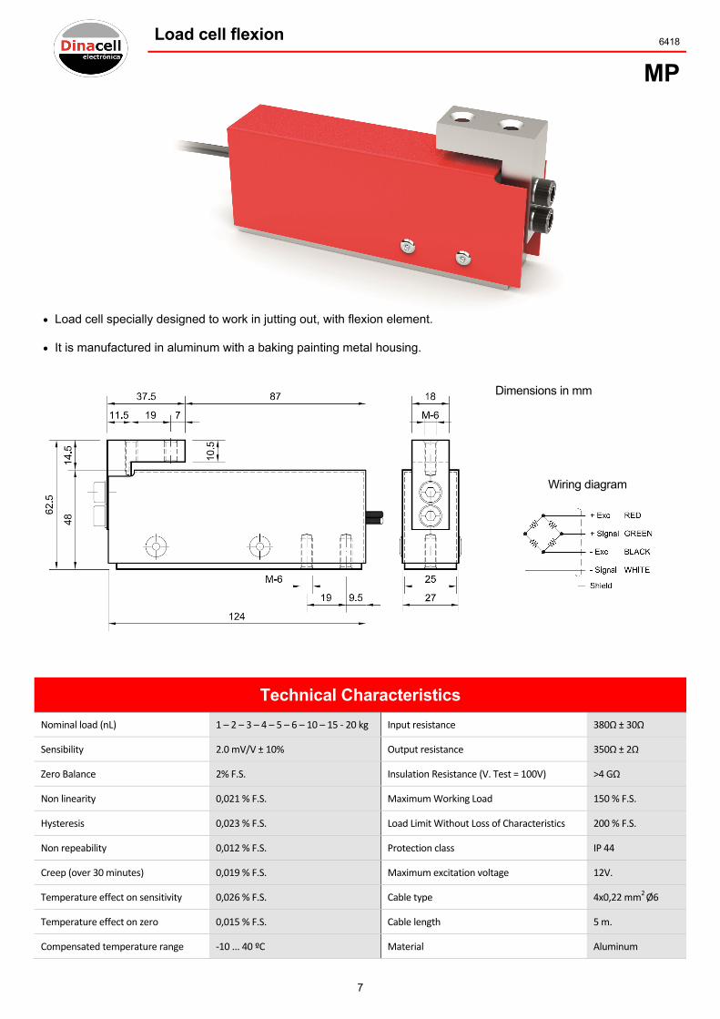
Load cell flexion 6418
MP
Load cell specially designed to work in jutting out, with flexion element.
It is manufactured in aluminum with a baking painting metal housing.
Dimensions in mm
Wiring diagram
Technical Characteristics
Nominal load (nL) 1 – 2 – 3 – 4 – 5 – 6 – 10 – 15 ‐ 20 kg Input resistance 380Ω ± 30Ω
Sensibility 2.0 mV/V ± 10% Output resistance 350Ω ± 2Ω
Zero Balance 2% F.S. Insulation Resistance (V. Test = 100V) >4 GΩ
Non linearity 0,021 % F.S. Maximum Working Load 150 % F.S.
Hysteresis 0,023 % F.S. Load Limit Without Loss of Characteristics 200 % F.S.
Non repeability 0,012 % F.S. Protection class IP 44
Creep (over 30 minutes) 0,019 % F.S. Maximum excitation voltage 12V.
Temperature effect on sensitivity 0,026 % F.S. Cable type 4x0,22 mm2 Ø6
Temperature effect on zero 0,015 % F.S. Cable length 5 m.
Compensated temperature range ‐10 ... 40 ºC Material Aluminum

8
6426 Load cell flexion
MP150
Load cells specially designed to work in jutting out, with flexion sensor element.
Dimensions in mm
Wiring diagram
Technical Characteristics
Nominal load (nL) 150 kg Input resistance 380Ω ± 30Ω
Sensibility 2,0 mV/V ± 10% Output resistance 350Ω ± 2Ω
Zero Balance 2% F.S. Insulation Resistance (V. Test = 100V) >4 GΩ
Non linearity 0,021 % F.S. Maximum Working Load 150 % F.S.
Hysteresis 0,023 % F.S. Load Limit Without Loss of Characteristics 200 % F.S.
Non repeability 0,012 % F.S. Protection class IP 44
Creep (over 30 minutes) 0,019 % F.S. Maximum excitation voltage 12V.
Temperature effect on sensitivity 0,026 % F.S. Cable type 4x0,22 mm2 Ø6
Temperature effect on zero 0,015 % F.S. Cable length 5 m.
Compensated temperature range ‐10 ... 40 ºC Material Aluminum

9
Load cell Compression 5212
BP
Compresion load cell developed to work with off-center loading.
Low profile sensing element.
Note: this load cell can be supplied with a botton lid.
Dimensions in mm
Wiring diagram
nL (t) ØA B ØC D E ØF G H
1 – 2 – 3 – 4 - 5 90 36 24 13 M‐8 (4) 70 12 23
10 – 15 - 20 115 42 32 13 M‐12 (4) 90 16 29
30 - 40 155 68 44 16 M‐16 (4) 125 20 52
Características técnicas
Nominal load (nL) 1 … 40 t Creep (over 30 minutes) 0,06% F.S.
Sensibility 1,4 ... 2,0 mV/V Maximum excitation voltage 12 V
Zero Balance 5 % F.S. Minimum insulation resistance (V.Test = 100V) 4 GΩ
Temperature effect on sensitivity 0,044% F.S. Maximum Working Load 150 % F.S.
Temperature effect on zero 0,035% F.S. Break Load >300 % F.S.
Compensated temperature range ‐10 ... 40 ºC Protection class IP67
Service temperature range ‐20 ... 60 ºC Cable type 4x0,22 mm2 Ø6
Input resistance 350 ± 3Ω Cable length 4 m
Output resistance 350 ± 2Ω Material Alloy steel
Hysteresis error 0,067 % F.S. Surface treatment Chemical nickel
Non linearity 0,04% F.S.

6479
BP
Lo
Co
Nomin
Sensib
Zero B
Comp
Servic
Non li
Hyste
Input
Outpu
P2093
oad cell spec
ommonly use
nal load (nL)
bility
Balance
pensated tempe
ce temperature
inearity
resis error
resistance
ut resistance
cially designe
ed in the aut
Wiring
erature range
range
ed to work in
tomotive indu
g diagram
compressio
ustry.
Technica
0,5 – 1 – 3 ‐ 5
2,0 mV/V ± 0
5 % F.S.
‐10 ... 40 ºC
‐20 … 60 ºC
0,044% F.S.
0,047 % F.S.
380 ± 10Ω
350 ± 2Ω
10
L
on.
al Charac
5 t Maxim
0,4 % Minim
Maxim
Break
Prote
Cable
Cable
Mate
Surfac
Load cell
cteristics
mum excitation
mum insulation
mum Working L
k Load
ection class
e type
e length
rial
ce treatment
l Compre
Dimens
s
voltage
resistance (V.Te
Load
ession
sions in mm
est = 100V)
12 V
4 GΩ
150 % F.S.
>300 % F.S.
IP67
4x0,22 mm2 Ø
4 m
Alloy steel
Chemical nic
Ø6
kel

11
Load cell Compression 6421
SK
Load cell specially designed for weighing silos, with anti-overturn support.
Manufactured with double shear element. Made of stainless steel or alloy steel with chemical nickel protection.
Support incorporates a low profile, treated with highly corrosion resistant paint.
Wiring diagram
Model Nominal load (nL) t. Dimensions in mm
A B C D E F G H J K L M
SKP 1 – 2 – 3 – 4 – 5 - 6 180 140 130 100 140 140 100 100 18 75 15 125
SKM 8 – 10 - 15 240 160 130 120 160 170 130 120 21,5 100 15 150
SKG 20 – 25 – 30 – 40 – 50 - 60 280 200 150 158 200 240 180 158 25 138 20 198
Technical Characteristics
Sensibility 2 mV/V Compensated temperature range ‐10 ... 40 ºC
Tolerance sensibility adjustment ± 0,1 % F.E. Input resistance 760 ± 20Ω
Zero Balance ± 1,5 % F.E. Output resistance 700 ± 4Ω
Maximum excitation voltage 24 V Minimum insulation resistance (V.Test = 100V) 4 GΩ
Non linearity ± 0,02 % F.E. Maximum Working Load 150 % F.E.
Non repeability ± 0,012 % F.E. Load Limit Without Loss of Characteristics 180 % F.E.
Combined error ± 0,029 % F.E. Break Load 300 % F.E.
Hysteresis ± 0,033 % F.E. Cable type Shielded / Length 6 x 0,22 mm2 Ø6 / 8 m.
Creep (over 30 minutes) ± 0,025 % F.E. Protection class IP67
Temperature effect on sensitivity ± 0,023 % F.E. Material (Load cell) Alloy steel
Temperature effect on zero ± 0,018 % / 5ºC Surface treatment Chemical nickel

12
6424 Load cell Traction
CT
Load cells specially designed to work in traction, with shear sensor element
Equipped with insulating cases of high mechanical resistance (750-5000 kg.)
Used with shackles
Wiring diagram
nL (kg.) A B C D ØE ØF G Cable type Cable length
750 – 1000 - 1500 110 50 24 75 19 17 26
4x 0,22 mm2 Ø6 4 m 2000 - 3000 140 60 30 90 25 21 33
5000 180 70 34 120 30 26 38
7500 – 10000 - 12000 220 110 48 130 45 -- -- 5 m
Technical Characteristics
Nominal load (nL) 0,75 – 1 – 1,5 – 2 ‐ 3 ‐ 5 – 7,5 ‐ 10 ‐ 12 t Maximum excitation voltage 12 V
Sensibility 2,0 mV/V ± 0,1% Insulation Resistance (V. Test = 100V) 4 GΩ
Zero Balance 1,5 % F.S. Input resistance 380 ± 10 Ω
Non linearity 0,021 % F.S. Output resistance 350 ± 2 Ω
Hysteresis 0,020 % F.S. Maximum Working Load 150 % F.S.
Creep (over 30 minutes) 0,017 % F.S. Load Limit Without Loss of Characteristics 180 % F.S.
Temperature effect on sensitivity ± 0,023 % F.S. Break Load 300 % F.S.
Temperature effect on zero ± 0,018 % F.S. Protection class IP67
Compensated temperature range ‐10 ... 40 ºC Material Alloy steel
Service temperature range ‐20 ... 60 ºC Surface treatment Chemical nickel

13
Load cell Traction 6029
CTDC
Load cells specially designed to work in traction,with shear sensor elements
Double shear load cell for higher resistance to the break
Used with shackles
Dimensions in mm
nL (t) A B C D ØE
10 220 110 48 130 45
12
15 250 125 68 155 52
20
25 290 125 78 175 58
35 330 150 90 195 72
50
Wiring diagram
Technical Characteristics
Nominal load (nL) 10 – 12 – 15 – 20 – 25 – 35 ‐ 50 t Insulation Resistance (V. Test = 100V) 4 GΩ
Sensibility 2,0 mV/V ± 0,1% Input resistance 760 ± 20 Ω
Zero Balance 1,5 % F.S. Output resistance 700 ± 2 Ω
Non linearity 0,022 % F.S. Maximum Working Load 150 % F.S.
Hysteresis 0,027 % F.S. Load Limit Without Loss of Characteristics 180 % F.S.
Creep (over 30 minutes) 0,02 % F.S. Break Load 400 % F.S.
Temperature effect on sensitivity ± 0,023 % F.S. Protection class IP67
Temperature effect on zero ± 0,019 % F.S. Cable type 6x0,25 mm2 Ø6
Compensated temperature range ‐10 ... 40 ºC Cable length 8 m
Service temperature range ‐20 ... 60 ºC Material Alloy steel
Maximum excitation voltage 12 V Surface treatment Chemical nickel

14
5190 Load cell Traction
CTG
(**) SC Simple Cut
DC Double Cut
Wiring diagram
Dimensions in mm
nL (t) A B C D ØE ØF G H (**)
3,2
250 80 26 199.5 21.5
6.25
60
70 SC
6,3 270
100
36 210 27 80
12 C 285
49 205
35.5 100
DC
L 320 242.5
16 C 300
57.5 209
43 115 L 360 269
25 C 360
110
68
240 53 8.5
130
L 400 280 140
35 C 400
130 270
59 12.5
100
162
L 440 310 155
40 512 160 90 350 72 16.5 191
50
Technical Characteristics
Nominal load (nL) 3,2 ‐ 6.3 – 12 – 16 – 25 – 35 – 40 ‐ 50 t Input resistance (**)
SC 380 Ω ± 10 Ω
Sensibility 1,4 ... 2,0 mV/V DC 760 Ω ± 20 Ω
Zero Balance 2% F.S. Output resistance (**)
SC 350 Ω ± 2 Ω
Number of intervals (n) 3000 DC 700 Ω ± 4 Ω
Temperature effect on sensitivity ±0,022 % F.S. Minimum insulation resistance (V.Test = 100V) 4 GΩ
Compensated temperature range ‐10 ... 40 ºC Load Limit Without Loss of Characteristics 150 % F.S.
Service temperature range ‐20 ... 60 ºC Break Load 300% F.S.
Storage temperature range ‐30 ... 70 ºC Protection class IP 67
Hysteresis error 0,033 % F.S. Cable type 4x0,22 mm2 Ø6
Non linearity 0,022 % F.S. Cable length 1,5 m
Creep (over 30 minutes) 0,030 % F.S. Material Alloy steel
Maximum excitation voltage 12V Surface treatment Chemical nickel
15
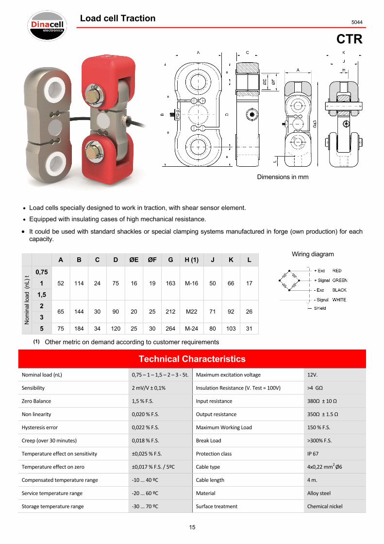
Load cell Traction 5044
CTR
Dimensions in mm
Load cells specially designed to work in traction, with shear sensor element.
Equipped with insulating cases of high mechanical resistance.
It could be used with standard shackles or special clamping systems manufactured in forge (own production) for each capacity.
A B C D ØE ØF G H (1) J K L
Nom
inal
load
(nL
) t 0,75
52 114 24 75 16 19 163 M-16 50 66 17 1
1,5
2 65 144 30 90 20 25 212 M22 71 92 26
3
5 75 184 34 120 25 30 264 M-24 80 103 31
(1) Other metric on demand according to customer requirements
Wiring diagram
Technical Characteristics
Nominal load (nL) 0,75 – 1 – 1,5 – 2 – 3 ‐ 5t. Maximum excitation voltage 12V.
Sensibility 2 mV/V ± 0,1% Insulation Resistance (V. Test = 100V) >4 GΩ
Zero Balance 1,5 % F.S. Input resistance 380Ω ± 10 Ω
Non linearity 0,020 % F.S. Output resistance 350Ω ± 1.5 Ω
Hysteresis error 0,022 % F.S. Maximum Working Load 150 % F.S.
Creep (over 30 minutes) 0,018 % F.S. Break Load >300% F.S.
Temperature effect on sensitivity ±0,025 % F.S. Protection class IP 67
Temperature effect on zero ±0,017 % F.S. / 5ºC Cable type 4x0,22 mm2 Ø6
Compensated temperature range ‐10 ... 40 ºC Cable length 4 m.
Service temperature range ‐20 ... 60 ºC Material Alloy steel
Storage temperature range ‐30 ... 70 ºC Surface treatment Chemical nickel

16
6031 Load cell Traction
TLCX
Load cell specially designed to work in traction
Manufactured in alloy steel
Anti-corrosion treatment of chemical nickel
Also available in staninless steel (depending on the capacity)
Dimension depending on customer requirements load
Connection options Bench mark chart to fill up
Kg. Nominal
load nL (kg.)
D
imen
sion
s in
mm
A
B
C
D
ØE
By output cable or M12 connector pannel
Output; several options (mV, mA, V)
Wiring diagram M12 connection
Technical Characteristics
Nominal load (nL) 1 … 60 t Creep (over 30 minutes) <0,037 % F.S.
Sensibility Aprox. 1,5 mV/V Insulation Resistance (V. Test = 100V) >5000 GΩ
Zero Balance 2% F.S. Input resistance 350 Ω ± 3 Ω
Temperature effect on zero <0,034 % / 5ºC Output resistance 350 Ω ± 1,5 Ω
Temperature effect on sensitivity 5 % F.S. Maximum Working Load 150 % F.S.
Compensated margin of temperature ‐10 ... 40 ºC Load Limit Without Loss of Characteristics 200 % F.S.
Power supply 10 to 30 Vdc Break Load >300% F.S.
Non linearity <0,034 % F.S. Protection class IP 66
Combined error <0,034 % F.S. Material Alloy steel
Combined error <0,07 % F.S. Surface treatment Chemical nickel
Hysteresis <0,07 % F.S.

17
Load cell Traction / Compression 7432
CTC
Load cells specially designed to work in traction and compression
nL (kg)
A B C D E
15
25
50
75
60 60 20 M-10 -
100
150
200
250
300
500
70 70 25 M-12 PG-9
750
1000
1500
2000
2500
80 80 25 M-16 PG-9
3000
5000 94 89 42 M-22x2.5 PG-9
Dimensions in mm
Wiring diagram
Technical Characteristics
Nominal load (nL) 15 ..… 5000 kg. Minimum insulation resistance (V.Test = 100V) 4 GΩ
Sensibility 2,0 (mV/V) ± 0,1 % Input impedance 380Ω ± 10 Ω
Zero Balance 1,5 % F.S. Output impedance 350Ω ± 1,5 Ω
Maximum excitation voltage 12V. Load Limit Without Loss of Characteristics 150 % F.S.
Hysteresis error 0,023 % F.S. Minimun breaking load 250% F.S.
Creep (over 30 minutes) 0,019 % F.S. Protection class IP 67
Maximum linerity error 0,021 % F.S. Cable type 4x0,22 mm2 Ø6
Compensated temperature range ‐10 ... 40 ºC Cable length 4 m.
Service temperature range ‐20 ... 60 ºC Material
15 ….. 75 Kg. Aluminum
Storage temperature range ‐20 ... 70 ºC 75 ….. 5000 Kg. Alloy steel
Temperature effect on sensitivity 0,026 % F.S. Surface treatment
15 ….. 75 Kg. Natural
Temperature effect on zero 0,015 % / 5ºC 75 ….. 5000 Kg. Chemical nickel
18
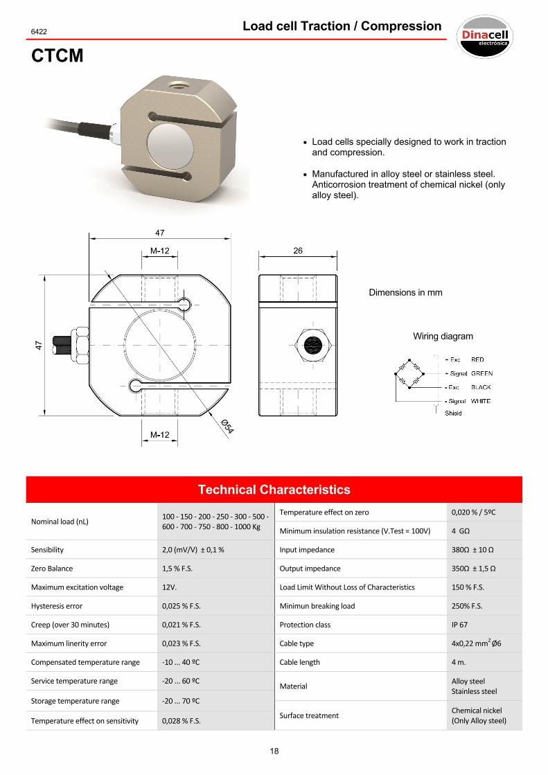
6422 Load cell Traction / Compression
CTCM
Load cells specially designed to work in traction and compression.
Manufactured in alloy steel or stainless steel. Anticorrosion treatment of chemical nickel (only alloy steel).
Dimensions in mm
Wiring diagram
Technical Characteristics
Nominal load (nL) 100 ‐ 150 ‐ 200 ‐ 250 ‐ 300 ‐ 500 ‐ 600 ‐ 700 ‐ 750 ‐ 800 ‐ 1000 Kg
Temperature effect on zero 0,020 % / 5ºC
Minimum insulation resistance (V.Test = 100V) 4 GΩ
Sensibility 2,0 (mV/V) ± 0,1 % Input impedance 380Ω ± 10 Ω
Zero Balance 1,5 % F.S. Output impedance 350Ω ± 1,5 Ω
Maximum excitation voltage 12V. Load Limit Without Loss of Characteristics 150 % F.S.
Hysteresis error 0,025 % F.S. Minimun breaking load 250% F.S.
Creep (over 30 minutes) 0,021 % F.S. Protection class IP 67
Maximum linerity error 0,023 % F.S. Cable type 4x0,22 mm2 Ø6
Compensated temperature range ‐10 ... 40 ºC Cable length 4 m.
Service temperature range ‐20 ... 60 ºC Material
Alloy steel Stainless steel
Storage temperature range ‐20 ... 70 ºC
Surface treatment Chemical nickel (Only Alloy steel) Temperature effect on sensitivity 0,028 % F.S.

19
Load limiter on Ropes 5777
LCA2
Dimensions in mm
Ref. Clamp groove size
"X"
Cable Groove
Range Rope Ø application
8 Ø6‐8 6 ...8mm.
13 Ø8‐13 8 ... 13mm.
16 Ø14‐16 14 ... 16mm.
20 Ø17‐20 17 ... 20mm.
23 Ø21‐23 21 ... 23mm.
Load limiter design for measuring the load on a single steel rope (traction ropes) with Ø 16 to 22mm.
Wiring diagram
Optional USB connector
Remarks:
To manage the orders, please specify the
following information:
Ø of ropes ...........................
Technical Characteristics
Nominal load (nL) 1,6 ‐ 3 t Input resistance 350 ... 400 Ω
Sensibility 1,4 ... 2,0 (mV/V) Output resistance 350Ω ± 2 Ω
Zero Balance 10 % F.S. Maximum Working Load 150% F.S.
Non linearity 0,11 % F.S. Load Limit Without Loss of Characteristics 200 % F.S.
Accuracy 0,25 % F.S. Protection class IP 65
Service temperature range ‐20 ... 60 ºC Cable type 4x0,09 mm2 Ø4.3 USB
Maximum excitation voltage 12V. Cable length 2 ‐ 4 m.
Insulation Resistance (V. Test = 100V) >4 GΩ Material Aluminum

20
4849 Load limiter on Ropes
LM
Optional USB connector
Wiring diagram
Dimensions in mm
Load limiter designed for measuring the tension on steel ropes that work on traction.
Remarks:
To manage the orders, please specify
the following information:
Ø of ropes ...........................
Mod. nL (t) A B C D ØE F G H
LMP 1 - 2 - 3,5 - 7 188 140 26 28 7 ... 26 65 41 M-6
LMG 8 - 10 - 15 - 20 305 260 36 32
12 ... 44 88
45
M-8
25 - 30 - 40 400 350 42 36 49.5
Technical Characteristics
Nominal load (nL) LMP 1 – 2 – 3,5 ‐ 7 t Minimum insulation resistance (V.Test = 100V) 4 GΩ
LMG 8 – 10 – 15 – 20 – 25 – 30 ‐ 40 t Input resistance 350 ... 400 Ω
Sensibility 1 ... 2 mV/V Output resistance 350 ±1.5 Ω
Zero Balance ±10 % F.S. Maximum Working Load 150 % F.S.
Non linearity (in working range) 0,108 % F.S. Protection class IP65
Accuracy 0,2 % F.S. Cable type 4x0,22 mm2 Ø6
Maximum excitation voltage 12 V Cable length 5 m.
Service temperature range ‐20 ... 60 ºC Material Alloy steel
Compensated temperature range ‐10 ... 40 ºC Surface treatment Chemical nickel
ROPE ØE
21
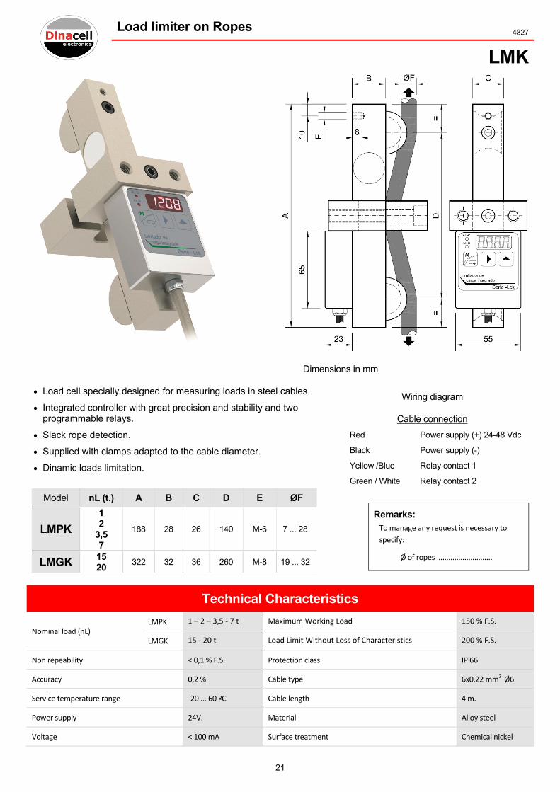
Load limiter on Ropes 4827
LMK
Dimensions in mm
Load cell specially designed for measuring loads in steel cables.
Integrated controller with great precision and stability and two programmable relays.
Slack rope detection.
Supplied with clamps adapted to the cable diameter.
Dinamic loads limitation.
Wiring diagram
Cable connection
Red Power supply (+) 24-48 Vdc
Black Power supply (-)
Yellow /Blue Relay contact 1
Green / White Relay contact 2
Remarks: To manage any request is necessary to
specify:
Ø of ropes ...........................
Model nL (t.) A B C D E ØF
LMPK
1 2
3,5 7
188 28 26 140 M-6 7 ... 28
LMGK 15 20
322 32 36 260 M-8 19 ... 32
Technical Characteristics
Nominal load (nL) LMPK 1 – 2 – 3,5 ‐ 7 t Maximum Working Load 150 % F.S.
LMGK 15 ‐ 20 t Load Limit Without Loss of Characteristics 200 % F.S.
Non repeability < 0,1 % F.S. Protection class IP 66
Accuracy 0,2 % Cable type 6x0,22 mm2 Ø6
Service temperature range ‐20 ... 60 ºC Cable length 4 m.
Power supply 24V. Material Alloy steel
Voltage < 100 mA Surface treatment Chemical nickel

22
4826 Load limiter on Ropes
LMS
Dimensions in mm
Load limiter designed for measuring the tension on steel ropes that
work on traction
Mod. LMS1 LMS2 LMS3 LMS4 nL (t.) 1 - 2 4 6 8 10
Rope Ø 6 – 7 ‐ 8 9 – 10 – 11 ‐ 12 13 – 14 ‐ 16 18 ‐ 20 22
A 125 142 165 185
B 25.5 31
C 29 31
Clamp LMS12 Ø5 ... 12 LMS34 Ø13 ... 22
Remarks:
To order this sensor it is necessary to
specify the following details:
Ø of ropes ...........................
Wiring diagram
Technical Characteristics
Nominal load (nL) 1 – 2 – 4 – 6 – 8 ‐ 10 t Minimum insulation resistance (V.Test = 100V) 4 GΩ
Sensibility 1 ... 2 mV/V Input resistance 350 ... 400 Ω
Zero Balance ±10 % F.S. Output resistance 350 ±1.5 Ω
Non linearity (in working range) 0,108 % F.S. Maximum Working Load 150 % F.S.
Accuracy 0,2 % F.S. Protection class IP65
Maximum excitation voltage 12 V Cable type 4x0,22 mm2 Ø6
Service temperature range ‐20 ... 60 ºC Cable length 4 m.
Compensated temperature range ‐10 ... 40 ºC Material Aluminum
23
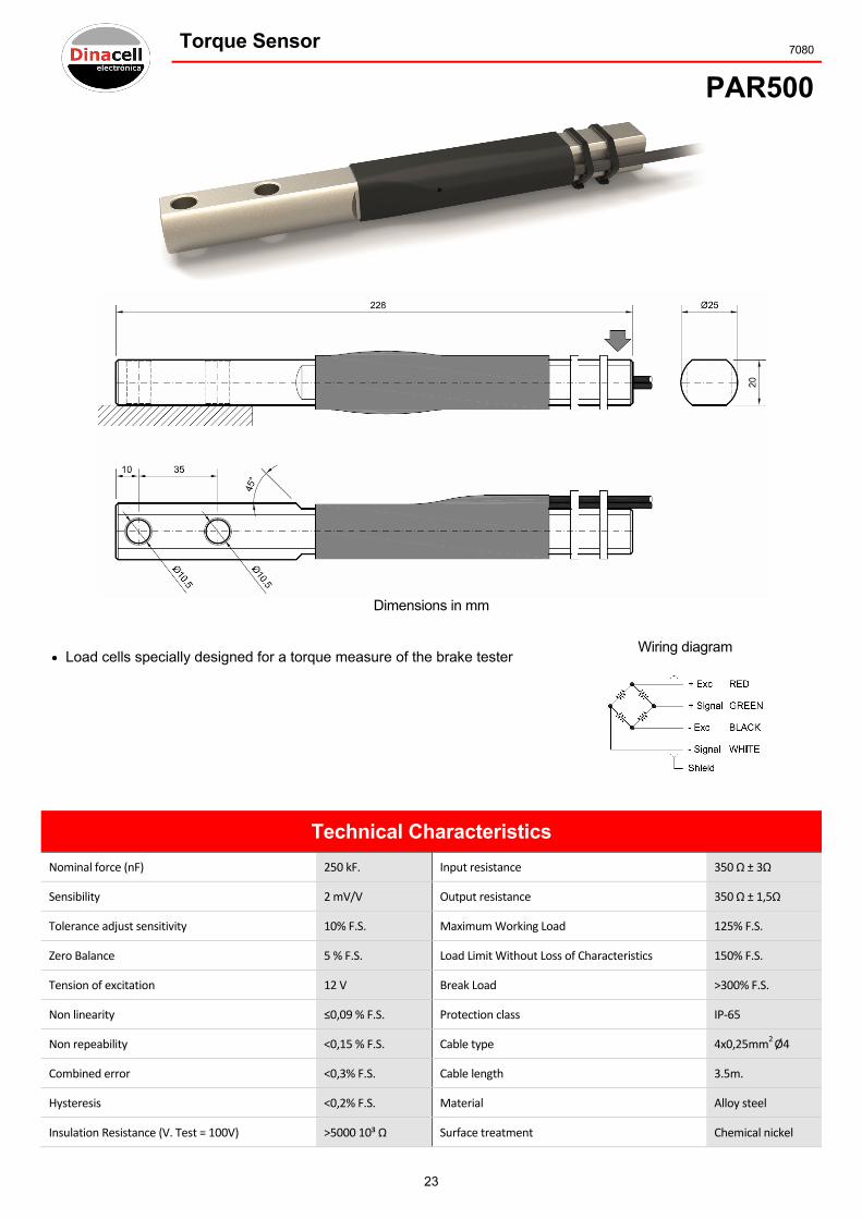
Torque Sensor 7080
PAR500
Dimensions in mm
Load cells specially designed for a torque measure of the brake tester Wiring diagram
Technical Characteristics
Nominal force (nF) 250 kF. Input resistance 350 Ω ± 3Ω
Sensibility 2 mV/V Output resistance 350 Ω ± 1,5Ω
Tolerance adjust sensitivity 10% F.S. Maximum Working Load 125% F.S.
Zero Balance 5 % F.S. Load Limit Without Loss of Characteristics 150% F.S.
Tension of excitation 12 V Break Load ˃300% F.S.
Non linearity ≤0,09 % F.S. Protection class IP‐65
Non repeability ˂0,15 % F.S. Cable type 4x0,25mm2 Ø4
Combined error ˂0,3% F.S. Cable length 3.5m.
Hysteresis ˂0,2% F.S. Material Alloy steel
Insulation Resistance (V. Test = 100V) ˃5000 10³ Ω Surface treatment Chemical nickel
24
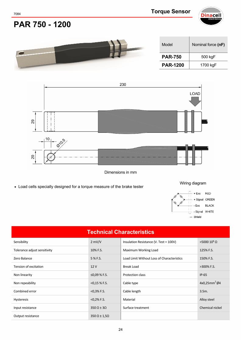
7084 Torque Sensor
PAR 750 - 1200
Model Nominal force (nF)
PAR-750 500 kgF
PAR-1200 1700 kgF
Dimensions in mm
Load cells specially designed for a torque measure of the brake tester Wiring diagram
Technical Characteristics
Sensibility 2 mV/V Insulation Resistance (V. Test = 100V) ˃5000 10³ Ω
Tolerance adjust sensitivity 10% F.S. Maximum Working Load 125% F.S.
Zero Balance 5 % F.S. Load Limit Without Loss of Characteristics 150% F.S.
Tension of excitation 12 V Break Load ˃300% F.S.
Non linearity ≤0,09 % F.S. Protection class IP‐65
Non repeability ˂0,15 % F.S. Cable type 4x0,25mm2 Ø4
Combined error ˂0,3% F.S. Cable length 3.5m.
Hysteresis ˂0,2% F.S. Material Alloy steel
Input resistance 350 Ω ± 3Ω Surface treatment Chemical nickel
Output resistance 350 Ω ± 1,5Ω

25
Load Pin 2856
BLP
Load pin bulon type used in weighing system and load limitation Nominal load nL (kg.).........................
Bench mark chart to fill up
Dimensions in mm
A ØB C D E F G H J ØK
Optional outputs 4-20 mA 0-10 V mV/V
Zero range 3,85 – 4,15V.
Output with nominal load 20 ± 0,3 mA
Excitation Voltage 10 ... 30 V.
Current consumption < 15mA
Zero range 0‐0,2 V.
Output with nominal load 10 ± 0,2 V.
Excitation Voltage 10 ... 30 V.
Current consumption < 15mA
Zero tolerance ± 0,1 mV/V
Sensitivity 1,2 ± 0,3
Max. excitation Voltage 24 V.
Output impedance 700 Ω
CONNECTIONS
CONECTO
R
CABLE
Technical Characteristics
Accuracy 0,2 % Maximum Working Load 150 % F.S.
Hysteresis < 0,07 % F.S. Break Load >300 % F.S.
Creep (over 30 minutes) 0,01 % F.S. Load Limit Without Loss of Characteristics 200 % F.S.
Temperature effect on sensitivity 0,044 % / 10ºC Protection class IP 65
Temperature effect on zero 0,035 % / 5ºC Cable type 4x0,22 mm2 Ø6
Compensated temperature range ‐10 ... 40 ºC Cable length 5m.
Service temperature range ‐20 ... 60 ºC Material
Alloy steel Stainless steel
Insulation Resistance (V. Test = 100V) 4 GΩ / 100 V
26
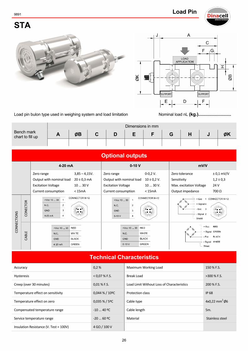
9891 Load Pin
STA
Load pin bulon type used in weighing system and load limitation Nominal load nL (kg.)...........................
Bench mark chart to fill up
Dimensions in mm
A ØB C D E F G H J ØK
Optional outputs 4-20 mA 0-10 V mV/V
Zero range 3,85 – 4,15V.
Output with nominal load 20 ± 0,3 mA
Excitation Voltage 10 ... 30 V
Current consumption < 15mA
Zero range 0‐0,2 V.
Output with nominal load 10 ± 0,2 V.
Excitation Voltage 10 ... 30 V.
Current consumption < 15mA
Zero tolerance ± 0,1 mV/V
Sensitivity 1,2 ± 0,3
Max. excitation Voltage 24 V
Output impedance 700 Ω
CONNECTIONS
CONECTO
R
CABLE
Technical Characteristics
Accuracy 0,2 % Maximum Working Load 150 % F.S.
Hysteresis < 0,07 % F.S. Break Load >300 % F.S.
Creep (over 30 minutes) 0,01 % F.S. Load Limit Without Loss of Characteristics 200 % F.S.
Temperature effect on sensitivity 0,044 % / 10ºC Protection class IP 68
Temperature effect on zero 0,035 % / 5ºC Cable type 4x0,22 mm2 Ø6
Compensated temperature range ‐10 ... 40 ºC Cable length 5m.
Service temperature range ‐20 ... 60 ºC Material Stainless steel
Insulation Resistance (V. Test = 100V) 4 GΩ / 100 V
27
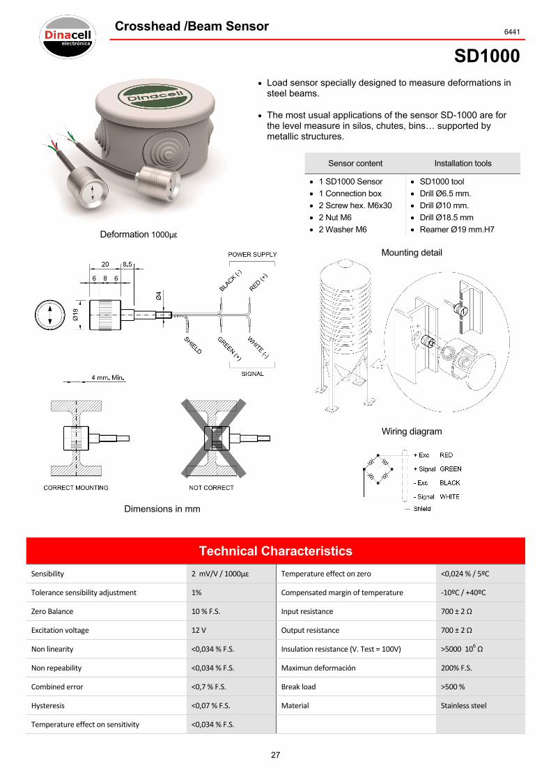
Crosshead /Beam Sensor 6441
SD1000
Deformation 1000µε
Load sensor specially designed to measure deformations in steel beams.
The most usual applications of the sensor SD-1000 are for the level measure in silos, chutes, bins… supported by metallic structures.
Sensor content Installation tools
1 SD1000 Sensor
1 Connection box
2 Screw hex. M6x30
2 Nut M6
2 Washer M6
SD1000 tool
Drill Ø6.5 mm.
Drill Ø10 mm.
Drill Ø18.5 mm
Reamer Ø19 mm.H7
Mounting detail
Wiring diagram
Dimensions in mm
Technical Characteristics
Sensibility 2 mV/V / 1000µε Temperature effect on zero <0,024 % / 5ºC
Tolerance sensibility adjustment 1% Compensated margin of temperature ‐10ºC / +40ºC
Zero Balance 10 % F.S. Input resistance 700 ± 2 Ω
Excitation voltage 12 V Output resistance 700 ± 2 Ω
Non linearity <0,034 % F.S. Insulation resistance (V. Test = 100V) >5000 106 Ω
Non repeability <0,034 % F.S. Maximun deformación 200% F.S.
Combined error <0,7 % F.S. Break load >500 %
Hysteresis <0,07 % F.S. Material Stainless steel
Temperature effect on sensitivity <0,034 % F.S.

28
3226 Crosshead /Beam Sensor
SV3000
Deformation 3000µε
Dimensions in mm
Sensor designed to work on traction and compression, especially for weighing depending on the deformations of steel beams.
Easy to install and suitable for any type of beam.
Application: load limitation on metallic structures, elevation systems (lifts, elevators, freight elevators...).
Wiring diagram
On the crosshead beam
Mounting on fixed point
Optional USB Connection
Technical Characteristics
Sensibility 2 mV/V @ 3000µε Minimum insulation resistance (V.Test = 100V) 4 GΩ
Service temperature range ‐20 ... 60 ºC Input resistance 350 ± 2 Ω
Tolerancia Sensibility ± 20 % F.S. Output resistance 350 ± 2 Ω
Zero Balance ± 10 % F.S. Cable type 4 x 0,14 mm2 Ø4
Maximum excitation voltage 12 V Cable length 6 m
Maximum deformation 150 % F.S. Material Alloy steel
Accuracy 0,2 % Surface treatment Chemical nickel

29
Control Unit 6541
ADS420
Dimensions in mm
ADS-420 Specially designed for signal conditioner of load cells.
Flexibility in the attachment of the unit (rail din or fixed by screws).
Adjust of the load without necessity of introducing a well known weight.
Feeding capacity of up to 8 load cells.
Compact box manufactured in ABS fireproof material.
Keyboard programming.
4 digits display with decimal point.
Calibrated in the factory.
Technical Characteristics
Cell signal measure range ±3,2 mV/V Alarm of relay 3A /250V
Accuracy 0.016 % Box material Fire proof ABS
Resolution of analog output 0‐10V 14 Bits Protection class IP‐50
Resolution of analog output 4‐20mA 15 Bits RS‐485 2 or 4 wire 40 access /seg.
Factory standard tolerance adjustment 0.3% Working temperature ‐10 … 60ºC
Power supply 230 Vac / 50‐60 Hz Maximum number of 350Ω cells 8

30
7089 Control Unit
INS2r
Dimensions in mm
INS-2r is a controller to visualize accurately and continuously the status of the load and the level content of silos and bins. The load is measured by load cells (SK, CFRT, SD-100 …).
It is possible to feed up to 8 load cells, so this allows to control 1 or 2 silos at the same time.
The display can show the weight of each silo individually or the total sum of both.
The device gives the possibility of setting a temporary zero to test an upload or a download
Technical Characteristics
Power supply 230 Vac Input channels 2 for two silos
Number of alarms 2 User interface Display 5 digits & 3 keys
Relay contacts 250V / 3A Programming By keyboard
Accuracy 0,01% F.S. Box Material Fire proof ABS
Temperature range ‐10 ... 60 ºC Protection class IP‐50
Resolution ±32000 points Fixing DIN rail
Communications RS‐485

31
Control Unit 5960
MR
Dimensions in mm
Features Technical characteristics
Low energy consumption
Easy programmable
3 Different operating modes
o Scale.
o Pick value reading.
o Pulse counter.
6 Digits display
Possibility of adjustment without weight
ADC with 16,000,000 points
USB communication
Power supply 230 V
Maximum power consumption 5 W
Relay contact voltage 250 Vac
Relay contact current 10 A
Load cell input accuracy 0,01 % F.S.
Max. Nº load cells to connect 12 Load cells of 350 Ω

32
5370 Control Unit
MR1
Dimensions in mm
Features Technical characteristics
Low Energy Consumption
Easy programmable
5 Different Operating Modes
o Scale.
o Pick value reading.
o Pulse counter.
o Tank unload.
o Dosing.
6 Digits Display
Possibility of adjustment without weight
ADC with 16,000,000 points
USB Communication
5 alarms with Relays.
Analogical Out
External input for cycle starting
Power supply 230 V
Maximum power consumption 5 W
Relay contact voltage 250 Vac
Relay contact current 10 A
Load cell input Accuracy 0,01 % F.S.
Analogical out 0‐20 Ma 4‐20 mA 0‐10 V
Max. Nº Load Cells to connect 12 Load Cells of 350 Ω
33
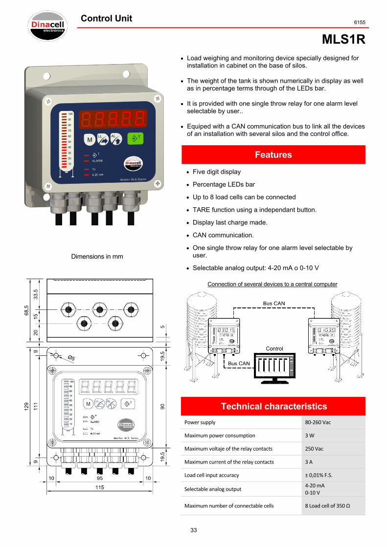
Control Unit 6155
MLS1R
Dimensions in mm
Load weighing and monitoring device specially designed for installation in cabinet on the base of silos.
The weight of the tank is shown numerically in display as well as in percentage terms through of the LEDs bar.
It is provided with one single throw relay for one alarm level selectable by user..
Equiped with a CAN communication bus to link all the devices of an installation with several silos and the control office.
Features
Five digit display
Percentage LEDs bar
Up to 8 load cells can be connected
TARE function using a independant button.
Display last charge made.
CAN communication.
One single throw relay for one alarm level selectable by user.
Selectable analog output: 4-20 mA o 0-10 V
Connection of several devices to a central computer
Technical characteristics
Power supply 80‐260 Vac
Maximum power consumption 3 W
Maximum voltaje of the relay contacts 250 Vac
Maximum current of the relay contacts 3 A
Load cell input accuracy ± 0,01% F.S.
Selectable analog output 4‐20 mA 0‐10 V
Maximum number of connectable cells 8 Load cell of 350 Ω

34
6491 Control Unit
VMA10
Signal conditioner
Power supply
It has two Inputs:
1. 18-24 VDC
2. Depending version:
48VAC
115VAC
230VAC
Analog outputs
0‐10V (Optional 0‐5V)
4‐20mA (Optional 0‐20mA)
Wiring diagram
The setting of zero and sensitivity adjustment is by potentiometers.
14 bits accuracy.
Dimensions in mm

35
Sums Box
Sums Box Mododel 2C-3R Device for connection of two load cells with outpur for devices to measure the sum of the applied loads. There are two potentiometers (P1 and P2) to adjust the individual output signal from each load cell
50Ω Resistor potentiometers
Dimensions 115x65x38mm..
Sums Box Model 4C-5R Device for connecting four load cells providing an output to devices that have to measure the sum of the applied loads. It is equipped with attenuators potentiometers for individual adjustment signal each two connected load cell.
50Ω Resistor potentiometers
Dimensions 160x120x74.5mm.
Junction Box Model 4-SP The junction box function is to merge the load cells near where there are located in order to carry a single cable to the measuring device, making easier the wiring to the equipment.
Dimensions 161x81x67mm.
NOTE: Every connected load cell must have the same nominal load characteristics and output impedance.
Technical Characteristics
Material Box. ABS fireproof
Protection class. IP‐67
Box fixing with external screws in order to ensure the tightness.
36
Notes

37
Dinacell Subsidiaries
Dinacell Hong Kong In new global expansion scenery, Dinacell has the commitment to enhance the service to our Asian clients. Since 2013, the Hong Kong subsidiary is offering a quick response to the demand supplying directly from its warehouse based in Hong Kong covering the Asian market and assisting our clients in their most suitable product for their needs. The subsidiary brings the opportunity to have the highest European quality product with a short delivery time, with a competitive and more than satisfactory costumer relationship. Both are the sign of identity of Dinacell Electrónica. Our new office is located in the building of Admiralty Centre‐Tower II situated in the heart of Admiralty area Hong Kong Island.
11/F, Admiralty Centre Tower II, 18 Harcourt Road, Admiralty, Hong Kong
Phone.: +852 3975 3014 Fax : +852 3975 3000 www.dinacell.com
e‐mail: [email protected] / [email protected]
Dinacell Uruguay
Our company Dinacell Electrónica has established in 2013 a subsidiary in Montevideo (Uruguay), able to expand and promote our business in the American countries like Argentina, Brazil, Chile, Uruguay, Mexico and other countries from MERCOSUR. Dinacell Uruguay subsidiary will also cover up the demand and the logistic supply of the materials to all Latin American countries.
Calle Zabala 1327, Edificio Zurich, Oficina 210 11000 Montevideo (Uruguay)
Phone.: +598 291 667 44 Fax : +598 291 661 64 Celular : +598 937 254 28 www.dinacell.com
e‐mail: [email protected] [email protected]

DinacellMadrid (SHeadqua
DinacellHong KoAsian De
DinacellMontevidSouth Am
ElectrónSpain) arters
l Electróong (HK) elegation
l Electródeo (Urugmerican D
nica S.L.
nic, Limi
nica S.Aguay) Delegatio
38
ited.
A.
on

39
Dinacell Electrónica s.l. Pol. Ind. Santa Ana C / El Torno Nº 8 – 28522 - Rivas Vaciamadrid - Madrid Tel.: +34 913 001 435 - Fax.: +34 913 001 645 E-mail: [email protected] - http: //www.dinacell.com
Ref.: 9900-0018/03/16