Embed Size (px)
Citation preview

NASA TN D-1137
TECHNICALD-II37
NOTE
PROJECT ECHO-
ANTENNA STEERING SYSTEM
R. Klahn, J. A. Norton and J. A. Githens
Bell Telephone Laboratories
NATIONAL AERONAUTICS AND SPACE ADMINISTRATION
WASHINGTON September 1961
https://ntrs.nasa.gov/search.jsp?R=19980227961 2018-09-09T08:23:39+00:00Z


1E
g_
!
PROJECT ECHO--
ANTENNA STEERING SYSTEM
by
R. Klahn, J. A. Norton and J. A. Githens
Bell Telephone Laboratories
SUMMARY
The Project Echo communications experiment employed large,
steerable, transmitting and receiving antennas at the ground termi-
nals. It was necessary that these highly directional antennas be
continuously and accurately pointed at the passing satellite. This
paper describes a new type of special purpose data converter for
directing narrow-beam communication antennas on the basis of
predicted information. The system is capable of converting digital
input data into real-time analog voltage commands with a dynamic
accuracy of ±0.05 degree, which meets the requirements of the
present antennas.

!
b.A
--a
PREFACE
The Project Echo communications experiment was a joint
operation by the GoddardSpace Flight Center of the National
Aeronautics and Space Administration (NASA), the Jet Pro-
pulsion Laboratory (JPL), the Naval Research Laboratory
(NRL), and the Bell Telephone Laboratories (BTL). The
equipment described herein, although designed by BTL as
part of its own research and development program, was
operated in connection with Project Echo under Contract
NASW-110 for NASA. Overall technical management of Proj-
ect Echo was the responsibility of NASA's Goddard Space
Flight Center.
ii

CONTENTS
Summary................................Preface .................................INTRODUCTION............................SYSTEMCONSIDERATIONS....................ANTENNASTEERINGFORECHOI ..............
SystemPhilosophy.......................InputDataTransmission...................Digital-to-AnalogConverterOrganization........CounterDecoding........................Interpolation...........................
THE INSTRUMENTSERVOSYSTEM.............SystemMechanization.....................TrackingControlSystem...................SlewingControlSystem....................ResolverEncoding.......................
CONCLUDINGREMARKS.....................ACKNOWLEDGMENTS.......................
Page
iii1133446899
1113141617
iii


PROJECT ECHO-
ANTENNA STEERING SYSTEM _
by
R. Klahn, J. A. Norton, and J. A. Githens
Bell Telephone Laboratories
INTRODUCTION
Although satellite-following communications antennas could be slaved to optical or
radar trackers at each antenna site, the use of basic orbital information to generate an-
tenna steering instructions is expected to be more economical when many antennas and
sites are served. The latter method was used in the Echo I experiments and employed
the following steps:
1. Determine satellite positions by accurate radio observations and, from these,
calculate the basic satellite orbital elements
2. Use these elements to calculate future satellite positions
3. From these positions, compute pointing angles for the antennas.
In the Echo I experiment, these functions were performed by the Minitrack satellite
tracking network and the computing center at the Goddard Space Flight Center. The pre-
dicted angles were transmitted by teletypewriter from the Goddard computer at Washing-
ton to the Bell Telephone Laboratories antennas at Holmdel, New Jersey.
SYSTEM CONSIDERATIONS
Several factors affect the design of a data processing system for antenna steering.
In addition to these factors, the data processing system adopted must provide:
#The substance of this paper was published in the Bell SystemTechnicalJournal,Vol. XL,
No. 4, July 1961. It is republished here, with minor revisions, by permission of Bell
Telephone Laboratories.

1. Transmission of predicted pointing data from a computer location to the communi-
cation antenna site, and temporary storage there prior to each satellite pass
2. Assembly of the data from storage and synchronization to real time
3. Error checking and rejection of erroneous quantities
4. Conversion of the digital orders into analog command signals to control the an-
tenna drive mechanisms.
The most important factor affecting the transmission facility, storage medium, and data
reconstruction equipment is the sampling interval of the discrete pointing information de-
livered by the computer. We will use the term data point to denote one sample of this
information, and the term data-point interval to denote lhe interval between successive
points. A wide range of intervals is possible with various combinations of data trans-
mission rate, storage requirements, complexity of the conversion equipment, and re-
liability of performance. There is, at one extreme, the possibility of transmitting large
numbers of data points with short data-point intervals. Advantages of this approach
arise from two considerations. First, the digital-to-analog conversion process involves
straightforward conversion of each point into an equivalent analog command, simplifying
the conversion equipment and offering advantages in reliability. Second, the data interval
is short, and thus errors occurring in transmission, storage, or assembly from storage
cause only momentary effects. Disadvantages result fr,_m the large quantity of data re-
quired to describe each satellite pass. This places an i,xcessive load on the computer
and on the transmission and storage facilities.
!
At the other extreme lies the possibility of transm:tting fewer sets of pointing
angles with their derivatives at data-point intervals of .,nany seconds Interpolation be-
tween data points using these derivatives provides continuous pointing information. Re-
duction of data for each pass is obtained at the expense of more extensive calculations
by the computer and more complex conversion equipment at the antennas. There is a
trade between the data rate of the transmission and capacity of terminal storage facili-
ties on one hand, and the complexity of the data-convert;ion equipment at the antenna on
the other.
When long data intervals are used, reliability cons:derations become more compli-
cated. Discrete samples of position and higher derivat ves become initial conditions in
an integration process which extends over each data interval. Errors in transmitted data
which are not detected and removed affect the system f_r the duration of the data interval
However, in this case redundancy for automatic error c hecking can be applied to the en-
coded quantities without requiring prohibitively large amounts of data.
To summarize, the optimum data interval is a function of several factors including
the load imposed on the computer in the generation of error-correcting codes and higher-
order derivatives, the cost and availability of transmission links, and the complexity of
the data conversion equipment needed at each antenna.

v--t
,-4!
Other design considerations include the method used for conversion of the transmitted
digital data into antenna steering commands. There are two methods. The first employs
electronic decoding of digital pointing commands to equivalent analog signals; these may
then be used to direct a number of antennas at one site. A second method involves encod-
ing of the antenna shaft positions in digital form and a subtraction between the encoded
positions and the digital command signals. Here digital error signals are derived, which
are more easily converted to analog signals to actuate the antenna servos. The latter
method, preferred for precise antenna control, requires separate encoding mechanisms
and digital subtractors with each antenna mount.
ANTENNA STEERING FOR ECHO I
System Philosophy
In designing a system to transmit pointing instructions from the Goddard computer
to Holmdel and there convert them into antenna steering orders, many of the factors dis-
cussed above were considered. Uncertainties regarding expected orbital perturbations
of the balloon satellite placed emphasis on an approach that would provide updated point-
ing instructions after each satellite pass. The experimental nature of the project dictated
the use of inexpensive transmission and storage media, and a reasonably simple digital-to-
analog converter.
The Echo satellites were to be placed in near-circular orbits at altitudes of 800 to
1000 miles. Maximum angular tracking velocities would be under 1.5 degree per second,
and average velocities would be much lower than this. Of primary importance are the
dynamic range of the steering signals, the conversion precision needed, and the form of
analog signals required by the antenna control systems. To insure that data conversion
errors would not affect radio transmission characteristics, design error tolerances
were set at _-0.05 degree.
Continuous three-wire ac synchro voltages were required as outputs of the converter,
to command each antenna and optical mount control system. While direct conversion from
digital form to ac signals is possible, an approach using small intermediate servos to
position synchro transmitter units was more attractive. Pulse-time-modulation tech-
niques were used to position these servos. Digital input commands were converted into
pulse-position-modulated (PPM) signals. At the same time, the servo output shaft posi-
tions were monitored by precision resolver angle transducers and the resolver outputs
producedPPM signals of the same form. The two PPM signals were compared on a time
basis to create the error signals that positioned the servo units.

Input Data Transmission
A 4-second data-point interval was chosen, permitting the description of a single
satellite pass to be transmitted over a 60-word-per-minute teletypewriter channel in
approximately the time taken by the pass. The choice oJ a standard-speed teletype-
writer was influenced by two factors: conversion equipment was available at the God-
dard computer center to produce punched-paper teletypewriter tape from the com-
puter output; and this tape could be transmitted and reproduced at the antenna site to
provide economical data storage. The pointing data furrished are the azimuth and
elevation antenna angles computed for the geographic loe_ation at Holmdel. These are
supplemented by the average rates of azimuth and elevalion over the succeeding data
interval to permit a linear interpolation between data points.
!
Digital-to-Analog Converter Organization
The data format, scale factors, and coding were ch(,sen to minimize the digital-
to-analog converter equipment. Teletypewriter code coaabinations were used to denote
decimal data in an 8-4-2-1 binary code, with the fifth level of the tape being used as a
single redundant parity-check bit; this was possible because a total of only 14 charac-
ters was needed. Sequences of tape characters called z_ords represent the data-point
time, azimuth angle, elevation angle, azimuth rate, and elevation rate. Each word is
identified on thp tape by a "tag" code following the word. These tags also control the
switching of the words to the proper destination within the conversion unit. The use of
tags makes the operation less dependent on the sequenc(_' of words and makes the system
more tolerant of errors introduced by transmission lin_s.
The conversion unit assembles the data from tape, synchronizes it with real time,
and switches it to counting decoders, which produce PPM signals proportional to the digi-
tal data. The following paragraphs describe logical features of the conversion unit; the
operation of the counting decoders and conversion of th( PPM signals to analog com-
mands are described later.
In the digital-to-analog conversion unit (Figure 1), a photoelectric tape reader reads
the tape characters in sequence and converts the information to electrical signals, which
are introduced to a shift register used to assemble the serial information from the tape
into parallel words. The output of the word-assembly register feeds the counting decoders
and the time-comparison circuit. The other input to the time-comparison circuit is the
output of a local time counter which provides the conversion unit with real-time synchroni-
zation. Reader outputs are also applied to the tag decoder and the parity-check circuit.
These actuate the control unit and determine the action taken by the conversion unit.

L'-
I
DIGITAL IINPUT DATA
__CONTROL CIRCUIT
LOCAL TIME COUNTER
1TIME COMPARISON
1WORD ASSEMBLY REGISTER
_D 1 AZIMUTH 1
VELOCITY /
COUNTING /
L/ELEVAT'ON'J VELOCITY
1 COUNTING
DECODER
AZIMUTH
COARSE
COUNTING
DECODER
ELEVATION
I COARSE J
= COUNTING
DECODER
If AZIMUTHI
FINE I _
COUNTING[_
DECODER|
I
J
PPM
ELEVATIONI OUTPUTS
FINE I ._
COUNTING /
DECODER /
Figure 1 -- Data conversion unit for Holmdel, N.J.
A consideration of events occurring when a block of information is read from the tape
illustrates the operation of the conversion unit. Assume that the tape is stopped after the
reader has read a time tag. This tag identifies the word in position in the word-assembly
register as the time word corresponding to the time for the next data point. This time
word is compared in the time-comparison circuit with the contents of the local-time
counter. An affirmative indication from the time-comparison circuit causes a clock
pulse to indicate that the next data point should be decoded and tape reader action is
initiated. As the tape moves, each character is examined by the tag decoder. If the tape
character being read is not a tag, the contents of the word-assembly register are shifted
one digit to the right and the new character is entered on the left.
This process continues until a tag is encountered -- in this instance, the azimuth
quantity. Detection of the azimuth tag indicates that the azimuth angle is in position in
the word-assembly register and is ready for transmission to the azimuth-counting de-
coders. When a signal from the azimuth decoder indicates that it is ready to receive new
data, it is cleared and the new azimuth word is gated from the word-assembly register
as reading of the tape continues, each character being introduced to the word-assembly
register is examined until the elevation tag is encountered, causing the elevation word to
be placed in the elevation decoder. The rate information is handled similarly. After the
rate information has been transferred to the rate registers, reading of the tape continues
until the next time tag is detected. This indicates that the time word for the next block of
information is in the word-assembly register and is being compared with local time, to
complete the cycle.
Thelogicof thetime-comparisoncircuit is so designed that, for data blocks in the
proper sequence, the circuit will indicate a comparison _s soon as a time tag is detected
in the reader. This comparison holds for the 4-second iJlterval. If, when a time tag is
read, the contents of the word-assembly register and the local-time counter do not com-
pare, the control circuit causes the tape to advance to the next time tag and make another
comparison. If these times compare, it then proceeds as normal; if not, it stops and
gives an alarm. If the comparison should become good, tt turns off the alarm and pro-
ceeds as usual. Thus, in the event of a time-comparison failure, the system makes a
quick check to see that it has not somehow got behind, as may happen if an error makes
a data character look like a time tag. If the comparison check still fails, the alarm alerts
operating personnel. However, if, because of transmission drop-outs or errors, the sys-
tem has got a few seconds ahead, it will automatically correct itself, probably before any
manual maintenance routines can be initiated.
The redundant check bit with each character is checked as the character is read.
If a parity error is detected, the control circuit causes the tape to advance to the next
time tag. Thus, when an error is detected, the data block is discarded. As will be dis-
cussed later, the counting decoders continuously decode azimuth and elevation angles,
which are up-dated with the last-received rate information. This gives the system a
"coasting" feature, so that erroneous blocks of information may be discarded without
seriously affecting the system accuracy.
O_
I
Counter Decoding
The conversion of digital pointing commands involw's an intermediate conversion to
PPM signals, which is performed in high-speed sequential counting circuits. The concept
is very simple; the number to be converted is placed in a counter which is designed to
count toward zero. At the occurrence of a start pulse, this number is reduced by one unit
for each elapsed cycle of a stabilized clock pulse source. Zero-detection circuitry ar-
ranged on the counter output produces an output pulse when the counter reaches zero. The
time interval tld between the start pulse and the output is related to the clock frequency
f¢ and the number _ being decoded by the equation
e (1)tld = _c "
This time interval is clearly proportional to 8. Essential portions of the logical connec-
tions for a single counting decoder are seen in Figure 2.
By arranging the counter to recycle after it reaches its zero content, successive
zero-crossing output pulses are produced at time intervals equal to the product of the

START
PULSE, Po
TRANSFER
SIGNALS REGISTER CONTAINING 1
NUMBER TO BE DECODED, 8 I
CLOCK
FREQUENCY,p 'f'C
BINARY COUNTER
STAGE
1n [ TRANSFER GATES
llllllllj
l COUNTING DECODER\
S T
Ji .......
ZERO ,J._
CROSStNG_DETECTOR_
8_ AS PULSE POSITION
MODULATED SIGNAL
l
Figure 2 -- Counting decoder logic
clock frequency and the total number of states in the counting sequence.
arranging the repetition times of the start pulses t at
Moreover, by
kCtks ='T- k = 0,1,2 ....
c
(2)
where C is the total number of states in the counter, successive zero crossings times
tkd are always delayed from the start pulses by the same amount. That is,
1tkd = 7-- (8 + kC).
c
(3)
By subtracting Equation 2 from Equation 3, a repeated measure of e is generated as
tkd - tks = _" (4)
c
Each pulse position is modulated by the digital quantity placed in the counter. The
relationships among counter contents, start pulses, and outputs are usually shown as in
Figure 3. Although a number placed in the counter is regularly being counted around,
storage of that number is provided within the counter as the conversion process proceeds.
This results from the unique relation between the counter contents and time for each in-
put.
8
START PULSES
ts __n
CLOCK PULSES
_MAX
COUNTER
CONTENTS
ZERO CROSSING
OUTPUTS
IIIIIIIIIIIIIIIIIIIIIIIIIIIIIIIIIIIIIIIIllllllllllllllll IIIII1111111111111111_111111111111
J_
F---t,d---dI1 H H
fc fc.......... d
TIME
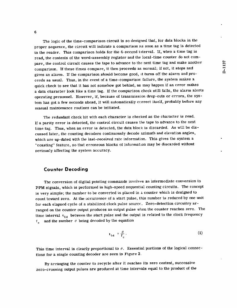
Figure 3 -- Counting decoder contents and woveforms
In real-time control system applications, the repetition rate of the decoding process
is important. This rate determines the bandwidth of signals that can be decoded. The
decoding resolution is, of course, determined by the number of states in the counter.
Counter stages operating at 5 Mc allow a sufficient range in resolution and repetition
rate.
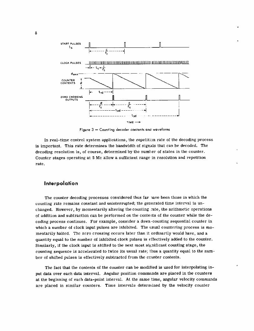
Interpolation
The counter decoding processes considered thus far t_ave been those in which the
counting rate remains constant and uninterrupted; the generated time interval is un-
changed. However, by momentarily altering the counting :ate, the arithmetic operations
of addition and subtraction can be performed on the conte_ts of the counter while the de-
coding process continues. For example, consider a down-counting sequential counter in
which a number of clock input pulses are inhibited. The usual countering process is mo-
mentarily halted. The zero crossing occurs later than it ordinarily would have, and a
quantity equal to the number of inhibited clock pulses is effectively added to the counter.
Similarly, if the clock input is shifted to the next most significant counting stage, the
counting sequence is accelerated to twice its usual rate; thus a quantity equal to the num-
ber of shifted pulses is effectively subtracted from the ceunter contents.
The fact that the contents of the counter can be modilied is used for interpolating in-
put data over each data interval. Angular position commands are placed in the counters
at the beginning of each data-point interval. At the same time, angular velocity commands
are placed in similar counters. Time intervals determined by the velocity counter

I
decoders are extracted and used as gating signals to alter the number of clock pulses fed
to the position counter decoders. Depending on the polarity of the velocity information,
the inputs to the position counters are either inhibited or shifted one stage for the duration
of this interval. In this manner, increments of position proportional to average velocity
are added to the position command several times during the data interval.
In the digital-to-analog converter, angle position commands are decoded to PPM
signals to provide a modulo 360-degree, or coarse, command and a modulo 3.6-degree, or
fine, command. Decoding is performed in a three-stage decimal counter, giving a decoding
resolution of 0.0036 degree. A counter clock frequency of 500 kc provides outputs at a
rate of 500 cps.
Rate information is decoded with a clock frequency of 5 Mc to PPM signals having a
50-kc repetition rate. One of these outputs is extracted 50 times per second, and controls
the counting of a decimal stage preceding the fine position decoder. The logical connections
for this control are shown in Figure 4. This yields a quasi-linear interpolation in steps
of 1/50 second duration, as is shown in Figure 5. The maximum deviation of this output
from true linear interpolation is a sawtooth function with a 50-cps repetition rate and a
maximum amplitude of 0.036 degree.
THE INSTRUMENT SERVO SYSTEM
The instrument servos convert the PPM signals produced by the counting decoders
into analog command signals for the communications antennas. The control systems of
these antennas use two-speed synchro control transformers as error detectors. The in-
strument servos position the two-speed synchro transmitters, which in turn command the
antennas. Two instrument servos are required: one to command the azimuth and the
other the elevation axes of the antennas. The two units are identical in design and con-
struction and, in the following, _ represents either the azimuth or elevation angle.
System Mechanization
Inputs to the instrument servos are the PPM pulse trains derived from the counting
decoders. Corresponding PPM follow-up signals are obtained from two angle-encoding
resolvers connected to the 1:1 and 100:1 speed shaft on the servo gear trains. The method
of encoding shaft positions with these resolvers will be described later. A block diagram
of the instrument servo system (Figure 6), shows the derivation of the position and velocity
follow-up signals, as well as the two-speed synchro transmitters which command the an-
tenna control system. A high-speed two-phase servo motor is used to position the instru-
ment servos, and a magnetic amplifier provides the power for the controlled phase of the
motor.

lO
5MCCLOCK
FROMWORD ASSEMBLY
"1Z-DECIMAL
RATE 1COUNTING
DECODER
1
ZERO
DETECTOR
50 KC 1
I PULSE WIDTH MODULATED
OUTPUT PROPORTIONALTO AVERAGE VELOCITY
COMMAND
I 5MC
7 I _ CLOCK FROM
PULSE WORD ASSEMBLYSTEERING
,_oo,oj "_1__ 1"l _F2;--_C'MAL',oo_CI_-DEC'_AL
...... |1 S"AGE ICLOCKt STAGE,--u_,Mm_ _ FINE I _ COARSEI STAGE I J CO[_Ni'ING I I COUNTING
f
PPM OUTPUTS TOINSTRUMENT SERVO
Figure 4 - Interpolation logic
i
t-=¢.o...,3
START PULSE,Is,FOR VELOCITYCOUNTER
I I I ! I I I I I I I I .... 1 1 I I 1 1
VELOC_YCOUNTERCONTENTS
VELOCITYCOUNTEROUTPUT
_-
I II II IIIII I I I ! I i
_.t;,_-t;,,=_ ....VELOCITY
OUTPUTAsGATE SETI--'11-"!1"1 r"l I'11"-I I-"11-117 !--I !-'11"-SIGNAL RESET a M u u I,,I u u u M u u u
/
VELOCITY GATE 5,ET _ - 1/50 SEC
EXTRACTED TO RESET - -_CONTROLINTERPOLATION I, I
.r-l.r-lf-lf-l_
I 2 M5START PULSE, tS, _ 2MS _ i
_R_S,T,ONI !i I ICOUNTER ____TIME DURATION DURING WHICH NORMAL
I COUNTING RATE OF POSIT ON COUNTER 15, ACCELERATED'I
POSITION C ........ _ I I _ll _ _ Ii _COUNTER _ I _ - _ too_ __1 _1 w_l -
Figure 5 -Quasi-linear interpolation

t'-¢O
)
-,,_b(PWM) + -
[PPM)
KILL
Y÷Z
z 1
OCl (PPM)
DC
IDEMODULATOR I
20,000
/SPEED
100
SPEED
8f (PPM) __ GEAR
_ _ TRAIN
500cPs_____l
LIT REF _
/ 36 SPEED
"I SPEED
Figure 6 -- Block diagram of the instrument servo
11
Tracking Control System
If the error between the angle _ called for by the counting decoders and the angle
encoded from the resolvers is less than 1.8 degrees, a system using _fk as a command
and _ as a follow-up signal controls the servo. For errors larger than 1.8 degrees a
slewing mode of operation is employed, which will be described presently. The circuitry
used in the tracking mode consists of the position feedback loop controlled by the fine
position command _fk, the velocity loop controlled by the velocity command _k, and the
feed-forward compensation represented by the block w in Figure 6.
In the fine position loop the follow-up pulse train 8t is phased with respect to the
decoded command pulse train _fk SO that for zero error the pulses of one train occur
halfway between the pulses of the other. The difference decoder is a flip-flop, with the
_fk pulse train applied to the "set" input and _f to the "reset" input. For zero error the
flip-flop spends equal time in the two states. For a nonzero error, the duration of one of
the states exceeds the other by an increment linearly proportional to the error. A current
proportional to the difference of the dwell times of the two states is used to drive one of
the control windings of the magnetic amplifier, which in turn controls the motor. Figure 7
shows the simplified circuit between the output of the difference decoder and the magnetic
amplifier. In absence of a "kill" signal, that is, with transistors T=A and T2B non-
conducting, the flip-flop drives the magnetic amplifier through alternate switching of

12
COMMAND
8£FOLLOW
UP
INHIBIT
GATE
I
<
<
T,_, I"
DRIVING
TRANSISTORS
-45V c_.0 c
c
{'R1 R <<
/
CONTROL
WINDINGS
- OF THE
MAGNETIC
AMPLIFIER
L"0"3
I
Figure 7 -- SimpliFied _gf circuit
transistors Tz._ and TIB. The gain of the fine position loop is set by the voltage applied
to R1 and R2 and the resistance n of the control winding circuit. To provide the re-
quired tracking accuracy the gain is adjusted so that an error of 0.01 degree gives ample
drive to overcome sticking friction of the motor and gear train.
The high gain of the fine position loop requires that it be disabled when the error is
greater than 1.8 degrees, to prevent it from interfering with the slewing mode of opera-
tion. The "kill" signal actuates the inhibiting gate composed of T2A and T2B , which dis-
ables the loop. The generation of the "kill" signal is indicated in Figure 6.
The velocity feedback loop is necessary to stabilize the system and improve its dy-
namic response. To prevent tachometric feedback from causing tracking errors pro-
portional to motor velocity, a signal proportional to the difference between the actual and
commanded motor speeds is used to drive the magnetic amplifier. The command signal
is obtained from the rate-counting decoder. It is a pul:_e-width-modulated (PWM) signal
whose average value is proportional to _k" The follow-up consists of an ac tachometer
followed by a demodulator producing a dc voltage proportional to the motor speed.
Ideally the feed-forward compensator (w) should p2 ovide a signal which is equal to that
required by the motor to follow the commanded input. Tracking a satellite requires oper-
ation of the servo at almost constant speeds for period_ which are long with respect to the
characteristic time constants of the servo. Hence the teed-forward path provides the
magnetic amplifier with a signal necessary to obtain the commanded velocity under
steady-state operation. Since the relation between the steady-state motor speed and the
magnetic amplifier control winding current is almost lnear over the range of speeds used
in tracking, the required block (w) of Figure 6 is a fixed attenuator. This is mechanized
by increasing the voltage gain of the _k decoder in the velocity loop, and therefore no ad-
ditional circuitry is needed.
E
The instrument servo-tracking control system provides a static accuracy of
±0.01 degree and maximum errors in the tracking mode of ±0.025 degree.
13
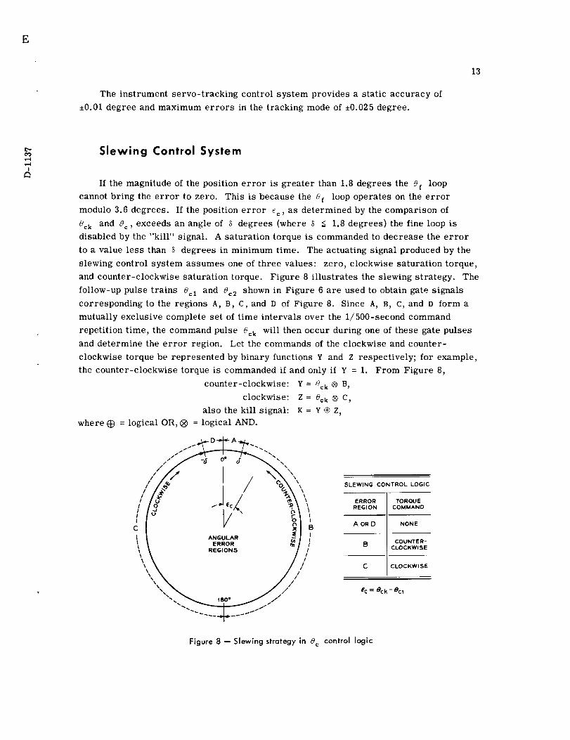
Slewing Control System
If the magnitude of the position error is greater than 1.8 degrees the Of loop
cannot bring the error to zero. This is because the 8¢ loop operates on the error
modulo 3.6 degrees. If the position error %, as determined by the comparison of
8¢k and 8¢, exceeds an angle of _ degrees (where S < 1.8 degrees) the fine loop is
disabled by the "kill" signal. A saturation torque is commanded to decrease the error
to a value less than 8 degrees in minimum time. The actuating signal produced by the
slewing control system assumes one of three values: zero, clockwise saturation torque,
and counter-clockwise saturation torque. Figure 8 illustrates the slewing strategy. The
follow-up pulse trains 8¢1 and 8¢2 shown in Figure 6 are used to obtain gate signals
corresponding to the regions A, B, C, and D of Figure 8. Since A, B, C, and D form a
mutually exclusive complete set of time intervals over the 1/500-second command
repetition time, the command pulse 8_ will then occur during one of these gate pulses
and determine the error region. Let the commands of the clockwise and counter-
clockwise torque be represented by binary functions v and z respectively; for example,
the counter-clockwise torque is commanded if and only if Y = 1. From Figure 8,
counter-clockwise: Y = 8ok ® B,
clockwise: Z = 8ck ® C,
also the kill signal: K = ¥® Z,
where _ = logical OR, ® = logical AND.
/ / ,I ,
I I ^NGO_^R\ k ERROR
\\ .,oo., /,\\ /'
iI
BII/
//
SLEWING CONTROL LOGIC
ERROR TORQUEREGION COMMAND
A OR [3 NONE
B COUNTER-CLOCKWISE
C CLOCKWISE
ec= 8¢k- ecl
Figure 8 -- Slewing strategy in 8c control logic

14
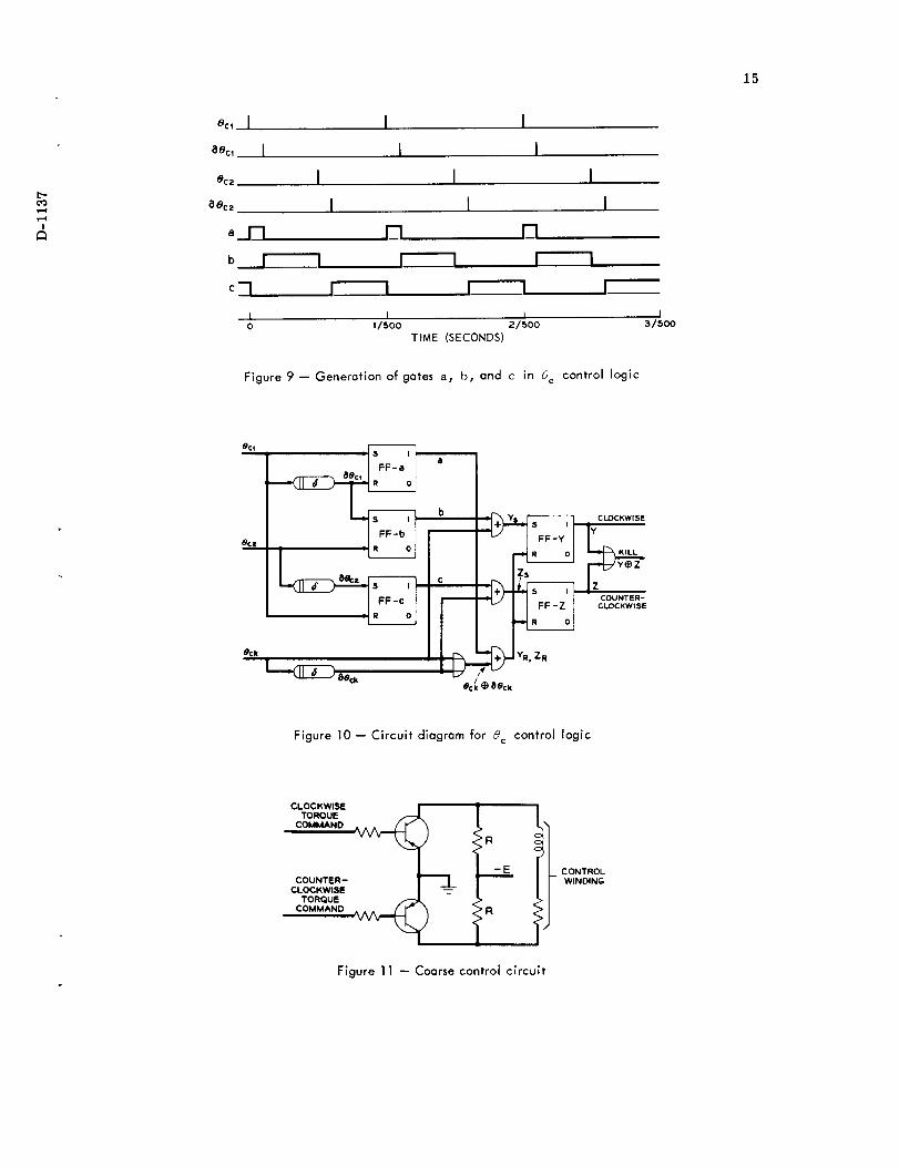
The timing pulses for the generation of the gate signals are obtained from 8¢1 and
ec2" The phase of the follow-up pulse train eel is adjusted so that for zero error it co-
incides with _¢k, the coarse command pulse train. The ec: follow-up signal is 180
electrical degrees behind ec2 • Circuits providing a time delay corresponding to _ de-
grees are used in the generation of the gate signals. Figure 9 shows the generation of
the gates a, b, and c by a set of flip-flops operated b) the follow-up signals. By com-
paring Figures 8 and 9 it is evident that:
@,
a=A=_D,
where _ is a delay operator of _ degrees.
The determination of the error regions is done 500 times per second. Flip-flops Y
and Z are set by the detection of error region B and C respectively; both are reset by
the detection of region A or O. The required output tc drive the motor is obtained from
one of the two flip-flops. Therefore:
Ys = _gck _ B = _gck ® b,
Z s : _gck ® C = _Sck ® _C = _gck ® c,
Yr = Zr = (_ck ® A) @ (_ck ® D) = (_ck ® A) • (_ck ®
= (_ck ® a) ® (_ck ® a) = (_cl: $ _ck) ® a,
K =Y$ Z,
_D)
where Ys and Yr are the set and reset inputs to the Y flip-flop respectively; and
similarly for the z flip-flop. A circuit diagram for the above logic is shown in Figure
10. The signals Y and z are applied to a pair of transistors driving the magnetic am-
plifier control winding No. 3 as shown in Figure 11.
Resolver Encoding
Shaft positions of the instrument servos are encoded to PPM signals by resolver
encoding techniques. Two precision resolvers are used with each instrument servo: the
first rotates 1:1 with the servo output to give a modulo 360-degree indication of the shaft
angle, the second rotates 100:1 with respect to the output, to give the modulo 3.6-degree
indication of the shaft angle. These ratios were chosen to match the coarse and fine out-
puts of the decimal counting decoders.
15
4
ec, i
aOcl I
_C2
80CZ
__r-I
b
I
I I
I I
I I I
I I I
I I
I I
i iO 1/500 2/5OO
TIME (SECONDS)
I
I3/SOD
Figure 9 -- Generation of gates a, b, and c in 8 c control logic
0¢1
ec_
8
b
8ocz c
ecl_ _) Beck
CLOCKWISEKiLL
COUNTER-CLOCKWISE
YR, ZR
Figure 10 -- Circuit diagram for _c control logic
CLOCHWISE / t ITORQUE _ / /
COUNTER- | _ _ IICLOCKWISE I _-- / II
TORQUE _ _'- ._1
CONTROLWINDING
Figure 11 -- Coarse control circuit

16
The method used to convert these resolver outputs to PPM signals has been
described in another paper,* but will be reviewed briefly here for completeness.
Electrically, each resolver is a mechanically variable transformer with couplings be-
tween the primary and secondary windings, both functions of the rotor angle 8R. When
excited by the ac signal
Ein = F_a x sin cot,
output voltages are the input voltage modulated by the sine and cosine of the rotor shaft
angle 8R. The resolver outputs are combined in phase-shifting networks which advance
the phase of the sine voltage by 77/2 degrees and add it to the cosine voltage. Thus a
phase-modulated signal results, according to:
Emax sin (c_t + 2) sin 8R + Emax sincot cos _)R = Em sin (cot + 8R).
The positive-going zero crossing of this signal is Lhe desired PPM signal repre-
senting the shaft position. Since the excitation voltage is 500 cps, a 0.18 degree move-
ment in the output of the instrument servo causes a change of 1 microsecond in the PPM
output of the coarse encoder. Similarly, a movement of 0.0018 degree causes a 1-micro-
second change in the PPM output of the fine encoder.
Resolver excitation is derived from the digital-to-analog converter central timing
by filtering and amplification of a 500-cps square wave. A zero-crossing detector,
similar to the one used for encoding the phase-shifted resolver output, is connected to
the resolver excitation. This output is the start pulse and therefore phase-locked to the
resolver excitation. It is used in the digital portion of the conversion equipment to time
the start of the counter decoder sequence.
!
CONCLUDING REMARKS
The above is a description of a new type of special purpose data converter for direct-
ing narrow beam communication antennas from predicled information. It is capable of
converting digital input data into real-time analog voltage commands with a dynamic ac-
curacy ±0.05 degree, which is sufficiently accurate for the present antennas. It employes
a moderate quantity of input data, and a reasonably simple digital-to-analog converter.
The single-parity-bit error detection provides moderate resistance to transmission
errors. During the Echo I experiments the number of errors in transmissions from
Goddard Space Flight Center were logged for 30 passes. Out of a total of 250 errors, the
*Kronacher, G., "Design, Performance, and Application of the Vernier Resolver," Bell
Sys. Tech. J. 36:1487-1500, November 1957
7
17
single-parity detection was effective in rejecting over 90 per cent. During these periods
the coasting features designed into the converter provided adequate antenna commands.
Using instrument servos as an intermediate step in the conversion process provides
convenient generation of two-speed voltages for commanding more than one antenna or
optical mount simultaneously. Separate synchro units can be placed on the gear trains for
each antenna, and each synchro can be excited by the particular frequency required by
that mount. Furthermore, choice of the ratios in the gear train provides outputs in the
"two-speed" combination required by each mount.
The use of counter decoders is quite attractive; they provide the storage necessary
to give continuous outputs to command the servos. Data interpolation makes possible an
input data interval of sufficient duration that ordinary teletypewriter transmission can be
used. The interpolation method outlined herein makes additional use of the counter de-
coders, without the need for a conventional arithmetic unit. The interconnections between
counters needed to perform interpolation require simple control logic. Since the decoders
and many of the low-speed operations in the converter operate synchronously, the additional
pulse rates needed for interpolation are already available from the timing section.
The resolver encoding technique converts instrument servo shaft positions into pulse-
position-modulated signals of the same general form as the counter output. These signals
are easily combined to form error signals to control the servos. In the same manner that
gear ratios can be chosen to provide outputs at a desired "two-speed" ration, the gearing
between resolver encoders can be chosen to yield PPM signals in any desired speed ratio.
This allows freedom of the number base in which the decoding process is performed.
ACKNOWLEDGMENTS
The authors are particularly indebted to J. C. Lozier for the system concept employed,
and to F. C. Young and W. J. Spiegel for their efforts in the electrical and mechanical de-
sign and fabrication of the instrument servos.
NASA-Langley, 1961