Embed Size (px)
Citation preview
E ....... ~ ..... ~ " .... . .... ~ L._ ... 'V '.':',
}
D
ELECTRICAL TESTING AND TROUBLES_HOOTING GUIDE . LOW PROFILE CAPACITOR EXCITED
AC NE GENERATORS
FIRST EDITION SEPTEMBER 2007
~ WESTERBEKE WESTERBEKE CORPORA TlON· 150 JOHN HANCOCK ROAO
MYLES STANDISH INDUSTRIAL PARK· TAUNTON MA 02780 WEBSITE: WWW.WESTERBEKE.COM --NAMIA Member Nalionnl Marine Manu/ac/urers Association ....,..,

TABLE OF CONTENTS
BC Generator (5.0/7.0 Kw) .................................... 2 Description .......................................... '" ..... , .. 2
BC Troubleshooting (Chart) MeccAlte ................. 3 Internal Wiring Schematic ............................ .3
Testing the BC Rotor· MeccAlte ........................ 4 BC Troubleshooting (Chart) Coliseum .................. 5
Internal Wiring Schematic ............................ .5 Testing the BC Rotor· Coliseum ......................... 6 Testing the Diodes ............................................... 7 Control Panel Components ................................. 7 BC Generators Troubleshooting .......................... 8
No AC Voltage ............................................... 8 Exciting the Generator ................................... 8 Reaction during Excitation ............................ 9 Testing the Exciter Windings ...................... 10 Exciter Winding Integrity ............................ 10 Testing Continuity ....................................... 11 Testing Capacitors ....................................... 11
BC Generator (Exploded View) ............................ 12 Wiring Diagram #46876 .. ................................... 13
Engines & Generators
1

Be GENERATOR ELECTRICAL TESTING The following field tests should be performed by a qualified technician. Proper safety precautions must be followed as most of these tests are executed with the generator operating or connected to ships power. AC voltage is lethal. If generator problems persist, contact your Westerbeke dealer.
-..v: WESTERBEKE Engines & Generators
1

Be GENERATORS 5.0n.o KW
DESCRIPTION The BC generator is a brushless, self-excited generator which requires only the driving force of the engine to produce an AC output. The stator houses two sets of windings; the main stator windings and the exciter windings. When the generator is started, residual magnetism in the four rotating poles induces a voltage in the stator which then generates an even larger voltage in the exciter windings. This mutual build up of voltage in the four rotating poles and in the exciter windings quickly reaches the saturation point of the capacitor(s) and a regulated energy field is then maintained in the stator. At the same time, this regulated field produces a steady voltage in the stator windings which can then be drawn off the generator's AC terminals to operate AC equipment. The generator is a single-phase, reconnectable 120 volt AC two-wire or 115 volt AC two-wire or 230 voltAC two-wire, at 50 hertz.
Wmdlng Connections: The single-phase synchronous generator has 4 stator leads and can be configured to . 120 volt output.
Bearings: The bearings are sealed type and permanently greased requiring no maintenance during their working life (approx. 30,000 hours).
PRELIMINARY CHECKING Before electrical testing, check for proper engine speedlhertz adjustment. Low engine speed wj]] cause low AC voltage output, high engine speed-high AC output.
Refer to WESTERBEKE'S operators manual or service manual for engine speedlhertz adjustment or for other possible engine related problems. .
Before testing, get a clear explanation of the problem that exists, be certain it relates to generator components.
A WARNING: AC and DC circuits often share tlie same distributor panel. Be certain to unplug AC power cords and shut down DCIAC Inverters. Simply switching Dff circuit breakers will not do the lob since It will stili leave hot wires on the supply side of the panel.
INTRODUCTION TO TROUBLESHOOTING The following test procedures can be used to troubleshoot WESTERBEKE'S 4 POLE DUAL EXCITER CIRCUIT BRUSHLESS GENERATORS. Due to the simplicity of the generator, troubleshooting is relatively easy.
Field testing and repairing can be accomplished with basis tools and repair parts which should include the following:
A quality multimeter (muItitester) capable of reading less than one ohm and with a specific diode testing function.
Basic electrical tools including cutters, soldering iron, wire strapper/crimper, terminal connectors, etc.
Repair parts such as diodes, fuses, bridge rectifier, etc.
A CAUTION: (ON SOLDERING) When soldering, use a large enough soldering Iron to get the job done quickly. Excessive heat will damage the diodes. Also make certain no soldering splashes onto the windings as It will melt the insulation.
ROTATING FIELD/AUXILIARY WINDINGS
WINDINGS WINDINGS
1\\10 sets of windings are found in the rotor assembly. An AC voltage is produced in two groups of windings as the rotor turns at its rated rpm. This AC voltage passes through each of the two diodes mounted on the isolated fixture just before the rotor canier bearing. The AC sine wave is changed to DC and this DC voltage is passed through the two groups of rotating field windings producing a DC field around these windings. This field affects the AC winding of the two main stator groups inducing an AC voltage in these windings that is available at the AC terminal block connections.
~ WESTERBEKE Engines & Generators
2

BC GENERATORS TROUBLESHOOTING CHART MECC ALTE (REFER TO THE WIRING SCHEMATIC BELOW)
A,I,e,BoD refer 10 Ihe componenfs oflhe INTERNAL WIRING OIAGRAM and Ihelr lesl procedures In Ihe following pages.
WINDING RESISTANCE VALUES (OHMS) 5.0KW 7.0KW
NOTE: 1hisfaultfinding chart is compiled assuming the engine is operating at the correct speedlhertz.
MAIN STATOR: #1 TO #3 0.4 0.2
FAULT
No AC Oulpul
Residual Voltage 4-6 VAC (Hoi N) al No-Load
High AC Oulput al No-Load
CAUSE TEST/CORRECTION
Shorted stator B Open stator B Shorted diode (two) A
Faulty capacitor (two) Open exciter Shorted exciter Engine speed (hertz) is 100 low Electrical connections are faulty
C I B Adjust'
Inspect wiring connections
#4 TO #6 0.4 0,2
ROTOR: (Each pair) 4,0 2,0
EXCITER: (Each winding) 3.9 2,5
CHARGE WINDING: 0,08 0,08
INTERNAL WIRING SCHEMATIC
.... - - - - - - - - -BRIDGE - - - - - - - - -Incorrect voltage tap e , on capacitor ' 0 , , Incorrect capacitor e : r-: : Incorrect hertz tap r - - - - - - • , , I r '
_________ ~_~~_c~...:~~:...~_~~_o:_d_(h_e_rtz_) ___ :_d.:.jU_st_,_ D!ODEq 1 L~-__ . ________ :- ___ .. ______ G~~U~j Low AC OulpUI Faulty rolor winding A : A: : 60-16DV Faulty diode A : :, B: --------------- DiDDE: :
Faulty capacitor I I ttl I ~ I
Voltage Drop Under Load (or al No-Load)
No BaUery Charge Low BaUery Charge
High Vollage Oulpul when Load Is applied
Unslable Vollage
Noisy Operallon
I I , Faulty diode A I' ,
l~~;:'"%'" !,.". l_ ------j [, t ~~ nFi6~ --~6[-6C,; Faulty Bridge rectifier D gOO U Faulty integral conlroller D ! G0 ~~: Blown fuse B I CAPACITDR CAPACITDR 1 Faulty wiring B 1 ____________________ J
Engine speed (hertz) is 100 high
Eleclrical connections are faulty, loose
Faulty support bearing
Generator rotor conneclion to engine is loose
Adjusl'
Inspecl wiring conneclions
Inspect rear bearing"
Check rotor security" "
A • ROTOR WINDINGS ' B • STATOR WINDINGS C • CAPACITOR WINDING o . BATTERY CHARGE WINDING
, Refer to the GENERATORS OPERATOR MANUAL ,. Refer to the GENERATORS SERVICE MANUAL
Engines & Generators
3
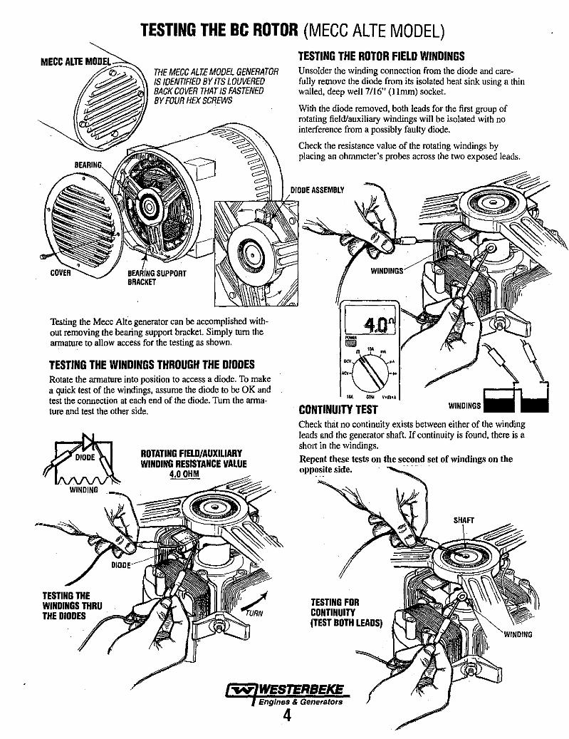
TESTING THE Be ROTOR (MECC ALTE MODEL)
THf MfCC ALTE MOOfL GfNfRATOR IS IOfNT/FlfO BY ITS LOUVfRfO BACK COVfR THAT IS FASTfNfD BY FOUR HfX SCRfWS
Testing the Mecc Alte generator can be accomplished without removing the bearing support bracket. Simply turn the armature to allow access for the testing as shown.
TESTING THE WINDINGS THROUGH THE DIODES Rotate the armature into position to access a diode. To make a quick test of the windings, assume the diode to be OK and test the connection at each end of the diode. Turn the armature and test the other side.
WINDING
ROTATING FIELD/AUXILIARY WINDING RESISTANCE VALUE
4.0 OHM
TESTING THE ROTOR FIELD WINDINGS Unsolder the winding connection from the diode and carefully remove the diode from its isolated heat sink using a thin walled, deep well 7116" (llmm) socket.
With the diode removed, both leads for the first group of rotating field/auxiliary windings will be isolated with no interference from a possibly faulty diode.
Check the resistance value of the rotating windings by placing an ohmmeter's probes across the two exposed leads.
CONTINUITY TEST
"\\ WtNDINGS~
Check that no continuity exists between either of the winding leads &nd the generator shaft. If continuity is found, there is a short in the windings. Repeat these tests on the second set of windings on the opposite side.
TESTING FOR CONTINUITY (TEST BOTH LEADS)
~ WESTERBEKE Engines & Generators
4
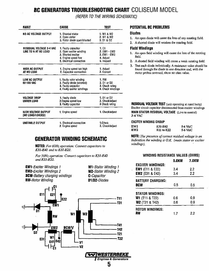
BC GENERATORS TROUBLESHOOTING CHART COLISEUM MODEL (REFER TO THE WIRING SCHEMATIC)
FAULT CAUSE TEST
NO AC VOLTAGE OUTPUT 1. Shorted stator 1. W1 & W2 2. Open stator 2. W1 & W2 3. Rotor diode open/shorted 3.01&02
REStOUAL VOLTAGE 3-4 VAC 1. Faulty capacitor 1. C1 LINE TO N AT NO LOAD 2. Open exciter winding 2. EW1 • EW2
3. Shorted exciter 3. EW1 • EW2 4. Engine speed low 4. Adjust 5. Electrical connection 5. Inspect
HtGH AC OUTPUT 1. Engine speed too high 1. Adjust AT NO LOAD 2. Capacitor connection 2. Correct
LOW AC OUTPUT 1. Faulty rotor winding 1. RW 60·100 VAC 2. Faulty diode (shorted) 2. 01 or 02
3. Faulty capacitor 3. Check raling 4. Faulty exciter windings 4. Check windings
VOLTAGE DROP 1. Faulty diode 1. 01 or 02 UNDER LOAD 2.Engine speed low 2. Check/adjust
3. Faulty capacitor 3 Check rating
HIGH VOLTAGE OUTPUT 1. Engine speed 1. Check/adjust (NO LOAOILOADED)
UNSTABLE OUTPUT 1. Electrical connection 1.Clteck 2. Engine speed 2. Check/adjust
GENERATOR WINDING SCHEMATIC NOTES: For 60Hz operation: Connect capacitors to E31-E41 and to Ell-Ell.
For 50Hz operation: Connect capacirors to E31-E42 and Ell-E22.
EW1-Exciter Windings 1 EW2-Exciter Windings 2 HCW-Battery charging windings RW-Rotor Winding
C1
E11r E~' •
~E22 EW1
W1
W1-Stator Winding 1 W2-Stator Winding 2 C-Capacitor D1/D2-Diodes
_------T11 ...-----T31
L--------T22 V1
L---V2
Engines & Generators
5
POTENTIAL BC PROBLEMS Diodes 1. An open diode will cause the loss of any rotating field. 2. A shorted diode will weaken the rotating field.
Field Windings 1. An open field winding will cause the loss of the rotating
field. 2.· A shorted field winding will cause a weak rotating field.
3. Test each diode individually. A resistance value should be found through the diode in one direction and, with the meter probes reversed, show no ohm value.
RESIDUAL VOLTAGE TEST (unit operating at rated hertz) Exciter circuit capacitor disconnected from exciter windings MAIN STATOR RESIDUAL VOLTAGE (Live to neutral) 3-4 VAC
EXCITER WINDING GROUP EWI EW2
E31-E42 Ell toE22
5-6 VAC 5-6 VAC
NOTE: The presence of correct residual voltage is an indication the winding is O.K. (main stator or exciter windings). '
WINDING RESISTANCE VALUES (OHMS)
5.0KW 7_0KW EXCITER WINDINGS: EW1 (E11 & E22) 3.4 2.2 EW2 (E31 & E42) 3.4 2.2
BATTERY CHARGING: HCW 0.5 0.5
STATOR WINDINGS: W1 (T11 & T22) 0.6 0.9 W2 (T31 & T42) 0.6 0.9
ROTOR WINDINGS: RW 1.7 2.2
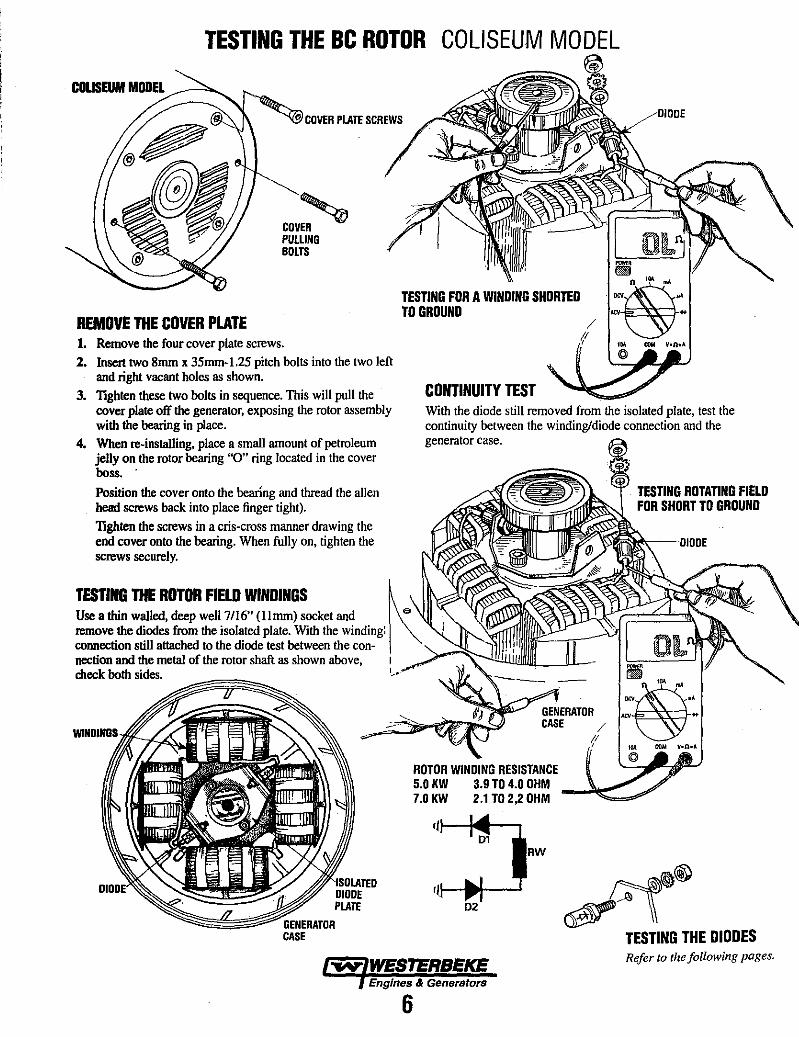
TESTING THE Be ROTOR COLISEUM MODEL
COLISEUM MODEL ____ -->0 ......
REMOVE THE COVER PLATE
COV~ PULLING BOLTS
1. Remove the four cover plate screws. 2. Insert two 8mm x 35mm-l.25 pitch bolts into the two left
and right vacant holes as shown.
TESTING FOR A WINDING SHORTED TO GROUND
CONTINUITY TEST 3. TIghten these two bolts in sequence. This will pull the cover plate off the generator, exposing the rotor assembly with the bearing in place.
With the diode still removed from the isolated plate, test the continuity between the winding/diode connection and the
4. When re-installing, place a smaIl amount of petroleum jelly on the rotor bearing "0" ring located in the cover boss ..
Position the cover onto the bearlng and tbread the allen head screws back into place finger tight).
TIghten the screws in a cris-cross manner drawing the end cover onto the bearing. When fully on, tighten the screws securely.
generator case.
TESTING THE ROTOR FIELD WINDINGS k Use a thin waIled, deep well 7116" (Umm) socket and . eo remove the diodes from the isolated plate. With the winding: connection still attached to the diode test between the con-nection and the metal of the rotor shaft as shown above, I check both sides.
~~~
ROTOR WINDING RESISTANCE 5.0 KW 3.9 TO 4.0 OHM 7.0 KW 2.1T0 2,2 OHM
Ijl--I4__.--. 01
RW
02
"'WN" WESTERBEKE Engines & Generators
6
TESTING ROTATING FIELD FOR SHORT TO GROUND
~~® ~\\
TESTING THE DIODES Refer to the following pages.
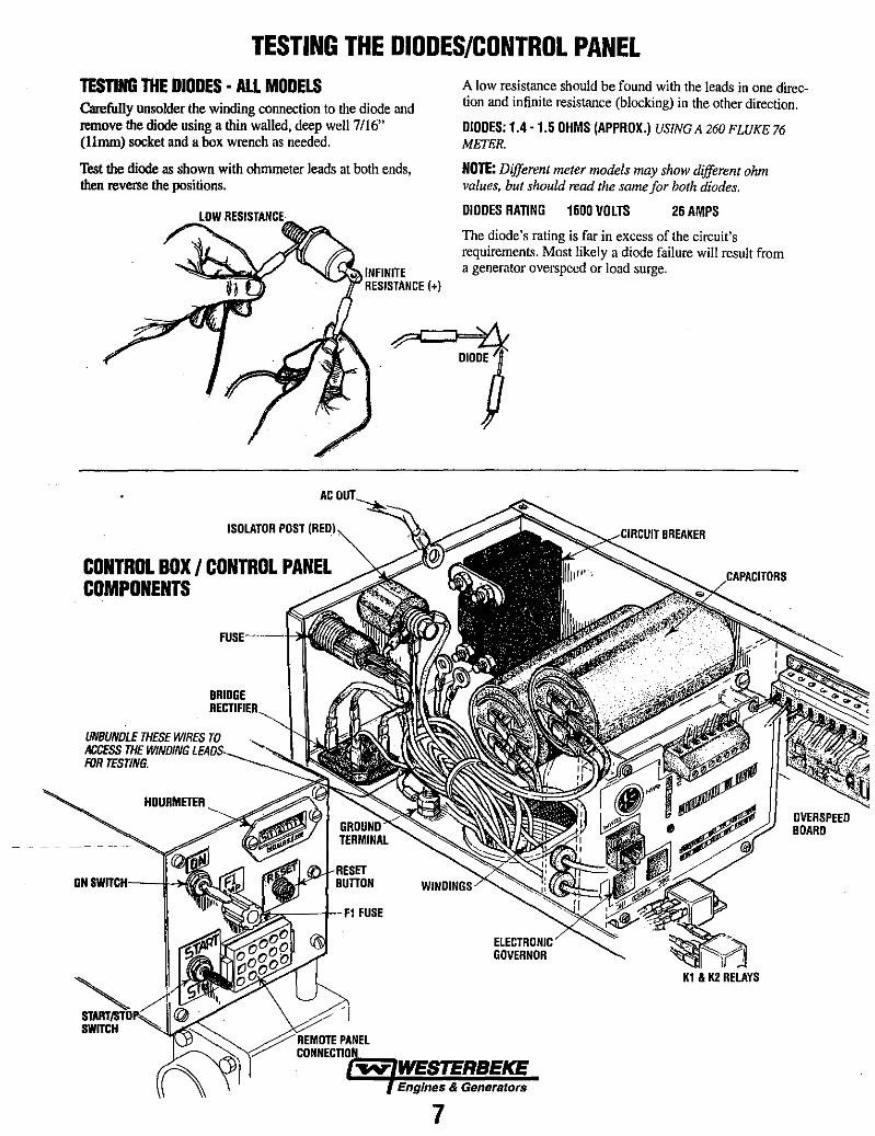
TESTING THE DIODES/CONTROL PANEL TESTING THE DIODES· ALL MODELS Carefully unsolder the winding connection to the diode and remove the diode using a thin walled, deep well 7/16" (Umm) socket and a box wrench as needed.
Test the diode as shown with ohmmeter leads at both ends, then reverse the positions.
CONTROL BOX I CONTROL PANEL COMPONENTS
BRIDGE
UNBUNDLE THESE WIRES TO ACCESS THE WINDING LtAIO!:i __
FOR TESTING.
HOURMETER
ON SWfircH---lI-~
SWfircH
A low resistance should be found with the leads in one direction and infinite resistance (blocking) in the other direction.
DIODES: 1.4 - 1.5 OHMS (APPROX.) USING A 260 FLUKE 76 METER.
NOTE: Different meter models may show different ohm values, but should read the same for both diodes.
DIODES RATING 1600 VOLTS 26 AMPS
The diode's rating is far in excess of the circuit's requirements. Most likely a diode failure will result from a generator overspeed or load surge.
OVERSPEEO BOARD
Engines & Generators
7
W1
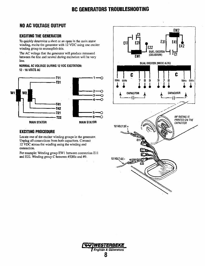
Be GENERATORS TROUBLESHOOTING
NO AC VOLTAGE OUTPUT
EXCITING THE GENERATOR To quickly detennine a short or an open in the main stator winding, excite the generator with 12 VDC using one exciter winding group to accomplish this. The AC voltage that the generator will produce measured between the line and neutral during excitation will be very low.
NORMAL AC VOLTAGE DURING 12 VDC EXCITATION: 12 ·16 VOLTS AC
.--------T11 .------T31
MAIN STATOR
EXCITING PROCEDURE
.'1:1
--0 2--0 3--0
__ 4-0
11::::5-0 6-0
MAIN STATOR
Locate one of the exciter winding groups in the generator. Unplug all connections from both capacitors. Connect 12 VDC across the winding using the winding end connection. For example: Winding group EWI between connection Ell and E22. Winding group C between #50Hz and #9.
12
r.iJCI
Ell E21 E31 E22
DUEL EXCITER EW! (COLISEUM)
OUAL EXCITER
50Hz 60Hz 7 8 9
• • ~ ~ .
12 VOLT DC +
9 50Hz 60Hz
~ . . ,~cy __ -,
MFRATING IS PRINTED ON THE CAPACITOR
Engines & Generators
8

Be GENERATORS TROUBLESHOOTING
REACTION DURING EXCITATION (Unit running-12VDC applied to winding)
No Conllnulty between lsolaled Slalor Windings and Ground
1. A very low AC outout and loading of the drive engine and a growling noise from the generator end.
This indicates a shorted stator winding to ground or the stator windings are shorted to each other. Isolate the winding groups and verify a short to ground. No continuity should be found between the two isolated stator winding groups.
2. No reaction from the generator or drive engine. No AC output.
W1
\\
This is an indication of an open in one of the main stator winding groups. Isolate the winding groups and verify an open winding.
L-------T22
W1
No Continuity between Isolated Stator Winding Groups
...-------T11
n~ 65 432 1
J !! J
TEST EACH OF THE WINDING LEADS INDIVIDUALLY AS SHOWN
THERE SHOULD BE NO CONTINUITY BETWEEN LEADS
~ WESTERBEKE Engines & Generators
9
TEST EACH WINDING TO CASE GROUND

Be GENERATORS TROUBLESHOOTING
TESTING THE EXCITER WINDINGS AC voltage can be measured across the capacitor electrical connections while the generator is operating. This voltage may be as high as 350 to 400 volts AC. 'This AC voltage build-up is accomplished as the exciter winding for each capacitor charges the capacitor and the capacitor discharges back into the winding. This flow of saturating AC in the exciter winding produces a phaseimbalance type of filed that affects the auxiliary windings of the rotor. The AC voltage reading is taken between the two electrical connections on each separate capacitor with the generator operating at its correct no load speed.
EXCITER WINDING INTEGRITY (RESIDUAL AC VOLTAGE) The condition of each exciter winding can be determined by the residual AC voltage each exciter winding should be producing with the generator running at proper no load speed. To do this: Unplug all connections from the capacitor. Locate the electrical connection for each winding end. Place your AC volt meter connects across these two connections. Start the generator and observe the residual AC voltage produced by the winding. Check the other exciter winding in the same way. Residual AC voltage lower than listed below will indicate a faulty winding.
RESIDUAL AC VOLTAGES (Each exciter winding) 5.0 KW E11 - E22 AND E31 - E42_ 5 - 6 VAC
'50·'9 AND '50 - #9_7·9 VAC 7.0KW E11 - E22 AND E31 - E42 _. 5 - 6 VAC
#50· #9 AND #50· #9_7' 9 VAC
THERE SHOULD BE NO CONTINUI1Y BETWEEN LEADS 50HZ AND 19 TO CASE GROUNDS
MEASURE THE RESISTANCE VALUE OF THE EXCITER WINDINGS BETWEEN THE END LEADS OF EACH WINDING
50Hz 60Hz
• •
Engines & Generators
10
MECCALTE MODEL
7 9
~ ~ . ~ . COLISEUM MODEL
CAPACITORCI
EIIr' E~ • ~E22
EWI CAPACITOR
MAIN STATOR WINDING RESISTANCE LESS THAN ONE OHM FOR EACH WINDING GROUP
MAIN STATOR RESIDUAL VOLTAGE LINE TO NEUTRAL 4-6 AC VOLTS (THIS INDICATES GOOD STATOR WINDINGS)

Be GENERATORS TROUBLESHOOTING
TESTING CONTINUITY Quick field check (no capacitance scale on meter).
Connect a digital ohm meter or analog ohm meter (high scale) to the capacitor terminals. The meter will register and arbitrary ohm value for the material in the capacitor. the meter's battery will then slatt to charge the capacitor and the ohm value will increase.
If the meter does not react as above, the capacitor is faulty.
The method above indicates a presumably good capacitor, but does not verify it's microfared rating as would be necessary when troubleshooting a capacitor whose MF rating has dropped causing a low AC voltage output. In such cases, the capacitors rating MUST be verified accurately.
A WARNING: Capacitors must bB dischargBd bBfof/J handling as thBY stOf/J BIBctrlcity and can pack a poten· tlally IBthal chargB even when disconnected from their power sourC/J.
DISCHARGING THE CAPACITOR
/
TESTING THE CAPACITOR(S)/ ->,,"'"
CAPACITOR RATINGS AND PART NUMBERS
25MFD
35MFD
55MFD
60MFD
Pn#046875
Pn#049627
Pn#048816
Pn#048018
Engines & Generators
11
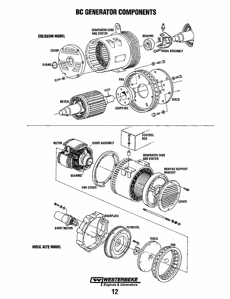
BC GENERATOR COMPONENTS
GENERATOR CASE
COLISEUM MODEL AND STATOR £~~
~~~ASSEMBLY
ASSEMBLY
BEARING SUPPORT
MECC ALTE MODEL
Engines & Generators
12

L
GENERATOR WIRING DIAGRAM #46876
e ,OIL PRESS ~ SWITCH IN/O)
in ~IJ-'r--!!.!" ''-'"-''' --++-----'rlF'----,
EXHAUST~ATURE SWITCH INIC)
• 14 RED/VIO
112 rtL/UO
"
•
~
•
IIIUI WATER TEMPERAT~E
SWITCH IN/C)
.:u: AUX •• OIL. PRESS
SWITCH [NJC)
117 RrD
.~ • . ;
• III nl~
•
" -
Ilf ~[DIYIO
20A CC CIRCUIT BREAKER
~FUSEBA . " .
I ON SWITCH
,-',+-_+"0:;00 METER
c~ (->1
BAntA COLEMAN CONIROlUR
~ 116 AU/VID
~~-\~~:~~~ ___ -ll"~"~"L-_____________ __ '--:~f!l, ;~g .~m:y~R[
"--- "IAC T£RIUJrAl ~UIl8[1I$.
OR CII[C~ IIII[ .IT~ VON I. ATTACH Uti lEAO or YOII TO RED IIIRE rltD!! CONIROlt[R. l. ATTACH OLAC~ LEAD or VON 10 EACH rURPt( IIIRE INDIYIDUALLY
OIIS£RV[ rOLARlTf
Engines & Generators
13
, .
~ WESTERBEKE Engines & Generators
WMDW601112D