Embed Size (px)
Citation preview
, .. " P JecK--
UNCLASSIFIED USNUOS Consecutive No. 316(First Revision)
U. S. NAVAL UNDERWATER ORDNANCE STATIONNEWPORT, RHODE ISLAND
00 ELECTROMAGNETIC RADIATIONIN SEA WATER
:. .- D D C
.,:cNOV 21 107-7 j
D D UTION STAT 1
Lj Aproved for public release;__j -Distribution Unlimited
Cm* 'UNCLASSIFIED
NU6S Consecutive .1-316- /e,.(First Revision)
U. S. NAVAL UNDERWATER ORDNANCE STATIONNEWPORT, RHODE ISLAND
PLECTROMAGNETIC tADIATIONIN SEA WATER1 .----
Prepared by:
A ug-,, m G. G. GOULDTechnical Director
J. H. BRANDTCaptain, USNCommanding
Task Assignment No, DI -B--f---TN STATqIK A000-283/32015/06070 ApprvUd or A" 7 '( Approved for public r.olo;7 3T Distribution Unlimited
usNUOS Consecutive No. 31C6kFirst Ruvision)
FOREWORD TOFIRST REVISION
This publication supersedesUSNUOS ConsecuLtive N-o. 3.16,diated April 1960, which should- bdstroyed in accordancewitLh regulations governing disposal of classified material.The overall intent and conclusions of the original reportremain unchanged.
! I .. ... .*
USNUOS Consecutive No. 31.6(First Revision)
ABSTRACT
A knowledge of' the effects of sea water on electro-magnetic waves is essential to any study of torpedo commandguidance systems using either radio or wire links. Thisreport presents a set of theoretical curves to illustratethe transmission of electromagnetic waves in a sea watermedium. The curves presented are for sea water at 17*C.They are intended as a theoretical starting point forfurther discussion or investigation.
Curves considered to be most descriptive and useful,and included in this report, are: (11 intrinsic impedanceof sea water medium versus frequency; (2)' wave length ,,felectromagnetic radiation in sea water; (3) attenuationversus frequency; (4) variation of transmission coefficientwith angle of incidence - for both vertical and horizontalpolarization of the incident wave; and (5) attenuation tobe expected when loss through the interface and through seawater are accounted for..
Conclusions that may be drawn from this survey are:(1) that there are probably no "holes" or "windows" in theelectromagnetic spectrum of sea water below 100 kilo-megacycles which may be used for communication with ordirect surveillance of submerged vehicles; (2) that radiocontrol or communications systems to be developed shouldemploy, wherever possible, vertically polarized transmittingantennae to maximize the signal passed through the air-seainterface and minimize the dependence of this signal onangle of incidence; and (3) that in the selection of acarrier frequency for proposed underwater vehicle controlsystems the minimum interface-sea water attenuation formula
derivd in this report be considered.
In general, this report confirms, in respect to electro-magnetic waves, a conclusion drawn by acousticians regardingsound waves; namely, that sea water is a very difficultmedium to use for the transmission of signnls.
ti
USNUOS Consecutive No. 316(First Revision)
ACKNOWLEDGMENT
The work accomplished by Mr. T. A. Galib,Head of the Feasibility Branch, Applied ScienceDepartment in the solution of equation 22 isgratefully acknowledged. The NAV UNDERWATERORDSTA IBM 650 computer was programmed toestablish its own first approximation andproceed to the single real value of N avail-able from each of the 255 equations required.
The prompt completion of this task made thecalculation of the transmission coefficientspossible.
ii i
USNUOS Consecutive No. 316
(First Revision)
I NTIRODUCT I ON
In the study of torpedo command guidance systems using0 t U- raio i in wire. i74 nks kcnowle dr of the effercts that
sea water has on electromagnetic waves is essential.
This report presents a set of theoretical curvesdescribing the transmission of electromagnetic waves in asea water medium. While there are nany references whichgive information on how to calculate the parameters ofinterest, these calculations have apparently not been carriedout to the point where curves could be drawn to show howindex of refraction, index of absorption, attenuation, wavelength, and intrinsic impedance vary with frequencies from100 cps to 100 kmcs. Two partial exceptions to this state-ment exist in references 1 and 2. The first gives curvesof refraction coefficient of sea water from 10 kilocyclesto 10 megacycles and a curve of attenuation versus depth forfrequencies from 10 to 500 kilocycles. The second gives atheoretical curve showing variation of attenuation ofelectromagnetic radiation in sea water over the range from1 megacycle to 100 kilo-megacycles.
Two other sets of curves are required for an understand-ing of radio transmission through the air-water interface.These are transmission coefficient versus angle of incidencefor various frequencies for both horizontal and verticalpolarization of the incident wave. These curves have beencalculated and plotted.
The curves presented here are for sea water at 170C.No attempt has been made to determine how far the valuesfor other temperatures will depart from those plotted.These curves are intended to serve as a handy guide toelectromagnetic radiation into and through sea water, andas a theoretical starting point for further discussion orinvestigation.
UNITS AND SYMBOLS
The symbols used throughout are the same as those usedin the principal reference (3. "Dielectrics and Waves"by A. Von Hippel). All quantities are expressed in therationalized m.k.s. system. The subscript 0 designates thequantity in a vacuum, subscript 1 the quantity in air, andsubscript 2 the quantity in sea water.
USNUOS Consecutive No. 316(First Revision)
Attenuation constant a = L I E nepersX E
Complex dielectric constant = E, - JE farad in
Complex index of refraction n = 0( - k)
Complex permeability /1-. =r I- j/J henry/rn
Complex propagatirn function y= a j I 1/in
Dielectric conductivity a- WE" mho0/m1
Dielectric constant (permittivity) E Ifarad/n
Electric field strength E volt/rn
Electric loss factor E"farad/in
impedance (intrinsic) Z = E/11 ohm
Index of absorption k =aif/3
Index of refraction n= XOi X
Magnetic field strength H amp/n
Magnetic loss factor Lhenry/n
Magnetic permeability p. henry/n
Phase constant = 2 7T/X I/rn
2
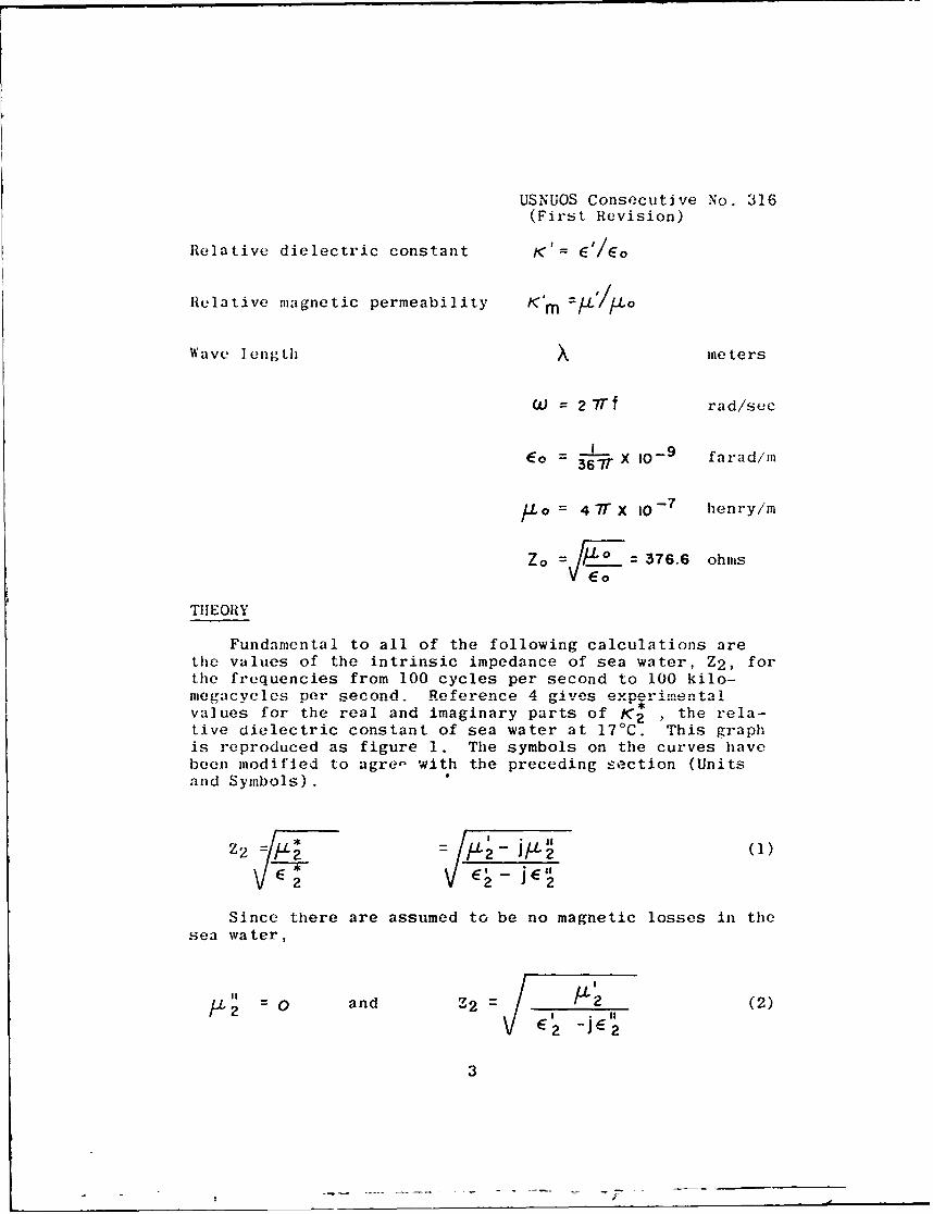
USNUOS Consecutive No. 316(First Revision)
Relative dielectric constant K E'/Eo
Relative magnetic permeability Km M 1
Wave length x meters
W = 2 7Tf rad/sec
Eo - 367" X I09 farad/im
)U o = 4 7T X 0-7 henry/m
Zo = ' .. = 376.6 ohmsE
THEORY
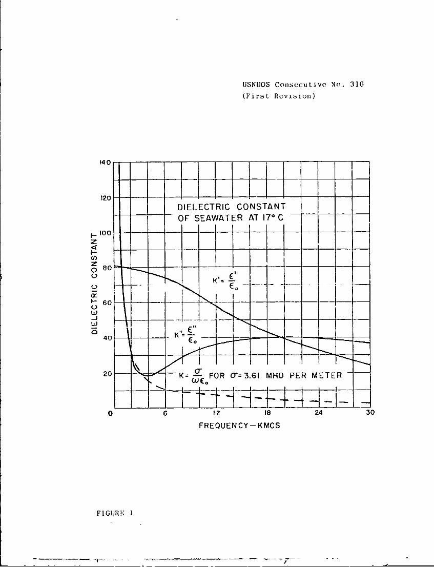
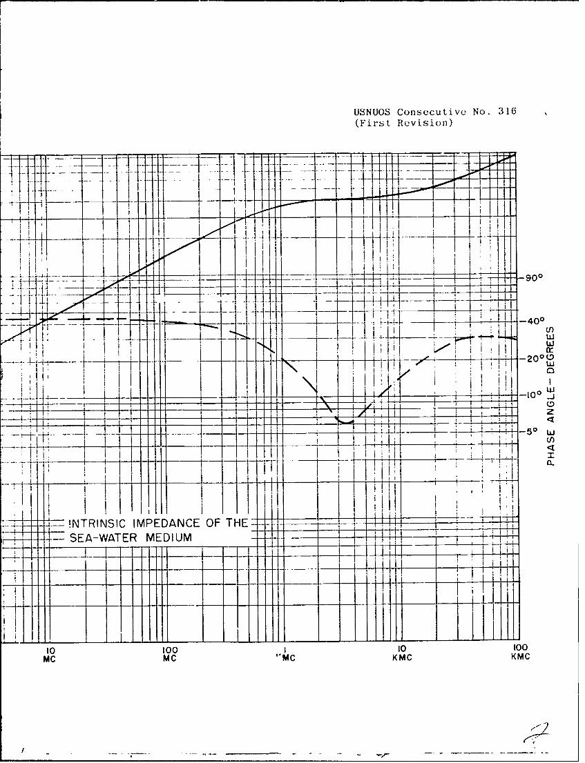
Fundamental to all of the following calculations arethe values of the intrinsic impedance of sea water, Z2 , forthe frequencies from 100 cycles per second to 100 kilo-mesacycles per second. Reference a gives *rmen tavalues for the real and imaginary parts of K 2 , the rela-tive dielectric constant of sea water at 170 C. This graphis reproduced as figure 1. The symbols on the curves havebeen modified to agre - with the preceding section (Unitsand Symbols) .
Z2 2-L = I-2 J'2()V 2' 2
Since there are assumed to be no magnetic losses in thesea water,
/12 0 and 72 2 (2)2 -2 W2
3
USNUOS Consecutive No. 316
(First Revision)
DIELEICTRIC CONSTANT
100------
z
crc-601_
25 40FiV9 K
2-01 K=- FOR 0-=3.61 MHO PER METER
0 6 12 18 24 30
FREQUENCY- KMCS
FIGUR!F 1
USNUOS Consecutive No. 316(First Revision)
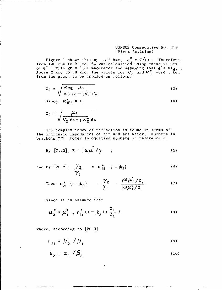
Figure 1 shows that up to 2 knc, O-/W Therefore,from 100 cps to 2 kmc, Z2 was calculates using these valuesof E" , with 0- = 3.61 mhoometer and assuming that E' = 8 1 EoAbove 2 kinc to 30 kmc. the values for K' and K" were takenfrom the graph to be applied as follows:
2M2 Ki Lo (3)
KEo -jK EO
Since Km2 (4)
Z2 = 0£
K2 :o- j 'i E
The complex index of refraction is found in terms ofthe intrinsic impedances of air and sea water. Numbers in
brackets jJ refer to equation numbers in reference 3.
By C7.25], Z = jW /yL ; (5)
and bv [2f 'Y )9 = n * (,-ik 2 ) (6
LI-
Then nl0 -jk 2 = *2/z 2 (7)21 2jWfL*/z 1
Since it is assumed tnat
2 1 2* , n * ( - k ) (8)
where, according to [20.3]
n21 = )2 1I, (9)
k2 a 2/12 (10)
4
I
USNUOS Consecutive No. 316
(First Revision)
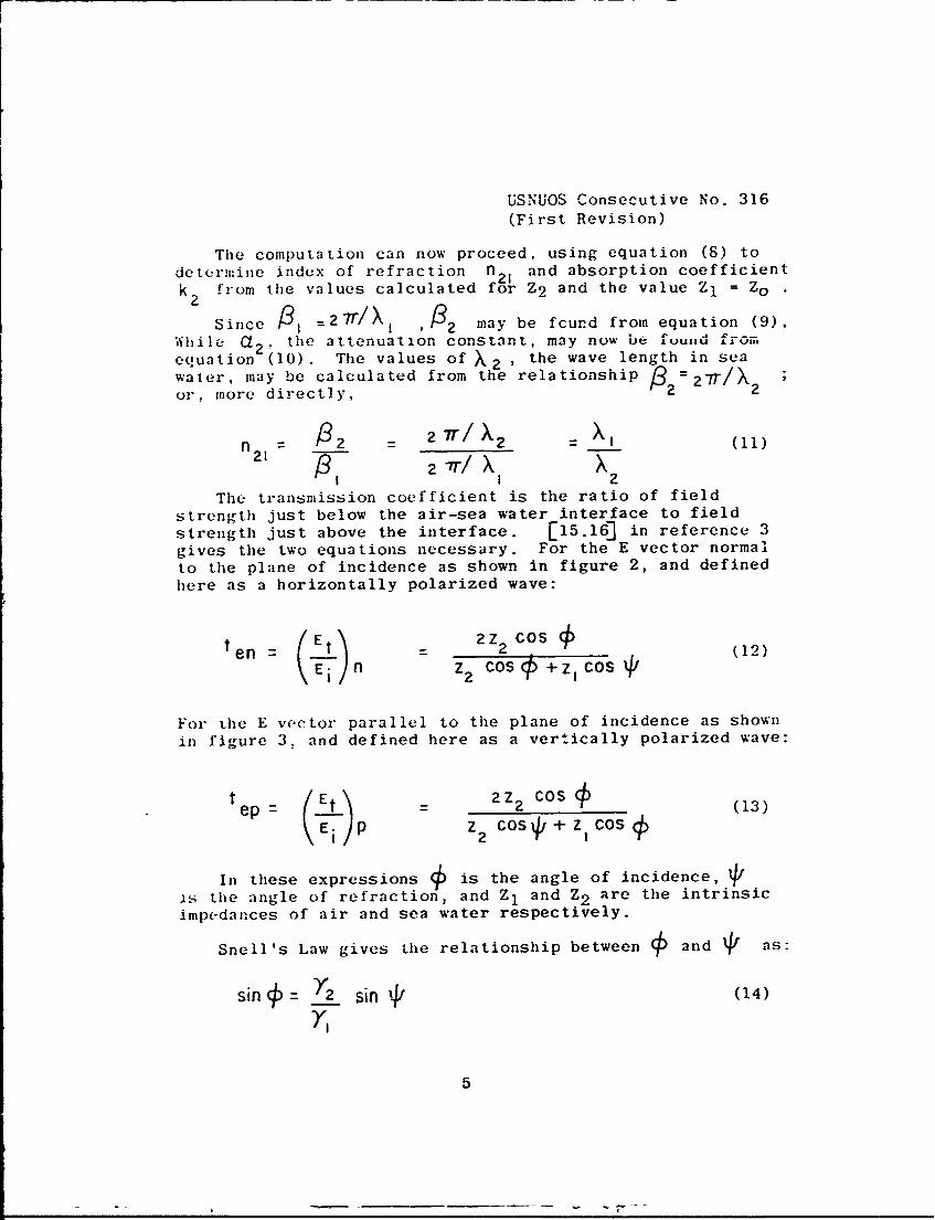
The computation can now proceed, using equation (8) todetermine index of refraction n21 and absorption coefficient
k 2 from the values calculated for Z2 and the value Z1 = ZO
Since 3 1 =2ir/XI , 2 may be fcund from equation (9),While Ca2 , the attenuatlon constant, may now be fvusud fromequation (10). The values of X2 the wave length in seawater, may be calculated from the relationship . 2 -T2r/X2or, more directly,
n 2 /'2 = 2 ir/X 2 : (11)
I 2The transmission coefficient is the ratio of field
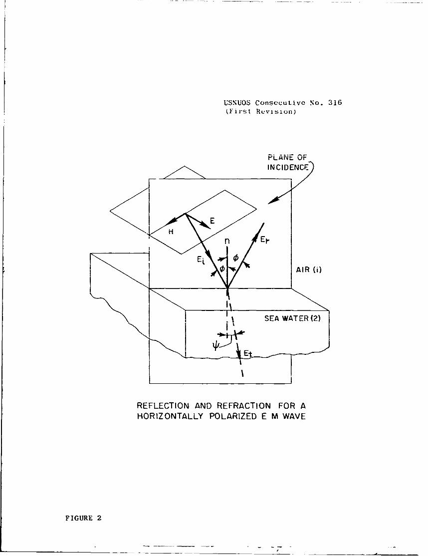
strength just below the air-sea water interface to fieldstrength just above the interface. [15.16] in reference 3gives the two equations necessary. For the E vector normalto the plane of incidence as shown in figure 2, and definedhere as a horizontally polarized wave:
ten - 2Z 2 Cos (12)Eln Z2 COSP +ZI Cos qI
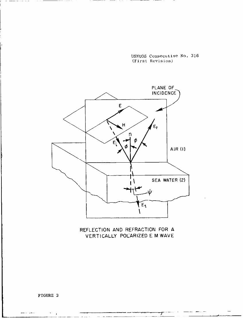
For the E vector parallel to the plane of incidence as shownin figure 3. and defined here as a vertically polarized wave:
pep o 2Z 2 C (13)
( E Z2 Cos4, + ZICos#
In these expressions is the angle of incidence, 11is the angle of refraction, and Z 1 and Z2 are the intrinsicimpedances of air and sea water respectively.
Snell's Law gives the relationship between and q as:
sin Y= "2 sin .41 (14)
Y,
USNUOS Consecutive No. 316(First Revision)
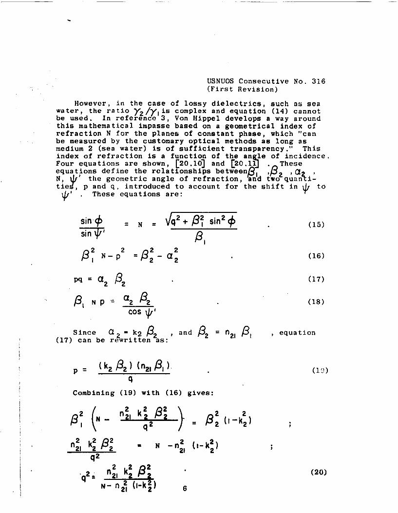
However, in the case of lossy dielectrics, such as seawater, the ratio y2 /y is complex and equation (14) cannotbe used. In reference 3, Von Hippel develops a way aroundthis mathematical impasse based on a geometrical index ofrefraction N for the planes of constant phase, which "canbe measured by the customary optical methods as long asmedium 2 (sea water) is of sufficient transparency." Thisindex of refraction is a function of the angle of incidence.Four equations are shown, [20.10] and [20. 1 Theseequations define the relationships between)9, ,2 aN, V' the geometric angle of refraction, and two quanti-ties, p and q, introduced to account for the shift in to4'. These equations are:
N S+, il .(5
$2
I N-p l 2 a 2 (16)
pq = a 2 132 (17)
N P = a2 (18)
COS *1
Since a 2 k 2 , and! 32 n2 l 3, , equation
(17) can be rewritten as:
p 2 ( ), (19)q
Combining (19) with (16) gives:
2 2k 22
,2 n2,k2 2 1 2n kz N - nm 0-P2 2
q2
*2 n 2 k 2 )82 (20)q f2 1 2 2N- ni (1-42) 6
USNUOS Consecutive No. 316(Fir-st Retvision)
PLAN'E OFIN CID ENCEJ
00 AIR (i)
I SEA WATER (2)
Et
REFLECTION AND REFRACTION FOR AHORIZONTALLY POLARIZED E M WAVE
FIGURE 2
USNUOS Consecutive No. 316(First Revision)
PLANE OFINCIDENCE
EE
RELETONAD EFATINFOV
VETCAL PLRIE E M AV
FIGUREn
USNUOS Consecutive No. 316
(First Revision)
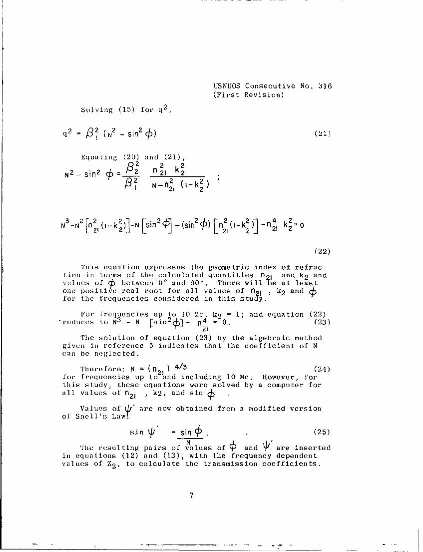
Solving (15) for q 2 ,
(1 )91 2 -sin 2 )()
Equating (20) and (21),2 2 2
N2 - sin 2 c 8= 2, k22 N-n (-k 2 )I 2i -2
2
N 3 -N 2 [n2, (-k 2 )] -N [ sin2j + (sin 2( /) ) [n21 (i-k 2 )] -n2 k2=o
(22)
This equation expresses the geometric index of refrac-tion in te;rms of the calculated quantities, n, and k 2 andvalues of ) between 0' and 900. There will be at leastone positive real root for all values of n , k2 andfor the frequencies considered in this study.
For frequencies up to 10 Mc k2 = 1; and equation (22)-reduces to N3 - N rs - 4 . (23)
21
'he solution of equation (23) by the algebraic methodgiven in reference 5 indicates that the coefficient of Ncan be neglected.
Therefore: N = (n 21 ) 4/5 (24)for frequencies up to and including 10 Mc. However, forthis study, these equations were solved by a computer forall values of n 21 , k2, and sin
Values of t' are now obtained from a modified versionof Snell's Law.
sin 1/' = sin . (25)N ,,
The resulting pairs of values of f and Vare insertedin equations (12) and (13), with the frequency dependentvalues of Z2 , to calculate the transmission coefficients.
7
USNUOS Consecutive No. 316
(First Revision)
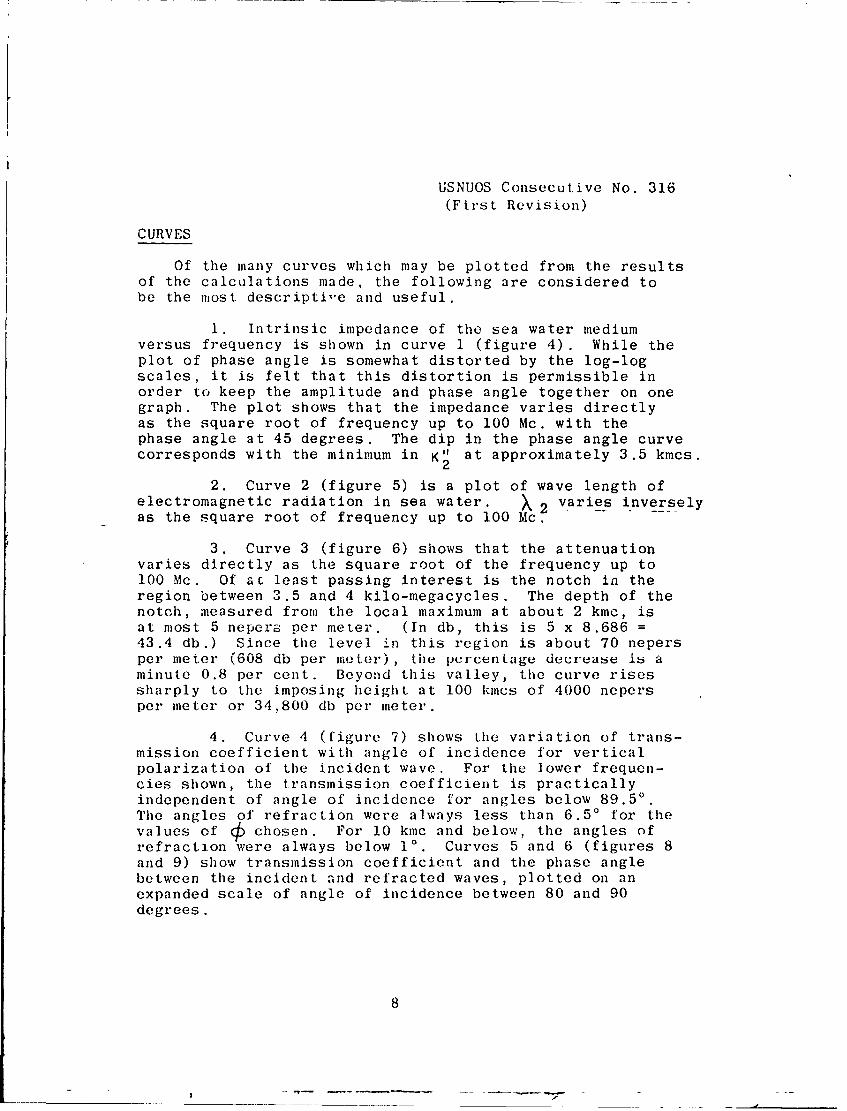
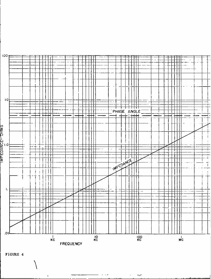
CURVES
Of the many curves which may be plotted from the resultsof the calculations made, the following are considered tobe the most descripti-e and useful.
1. Intrinsic impedance of the sea water mediumversus frequency is shown in curve 1 (figure 4). While theplot of phase angle is somewhat distorted by the log-logscales, it is felt that this distortion is permissible inorder to keep the amplitude and phase angle together on onegraph. The plot shows that the impedance varies directlyas the square root of frequency up to 100 Mc. with thephase angle at 45 degrees. The dip in the phase angle curvecorresponds with the minimum in K" at approximately 3.5 kmcs.
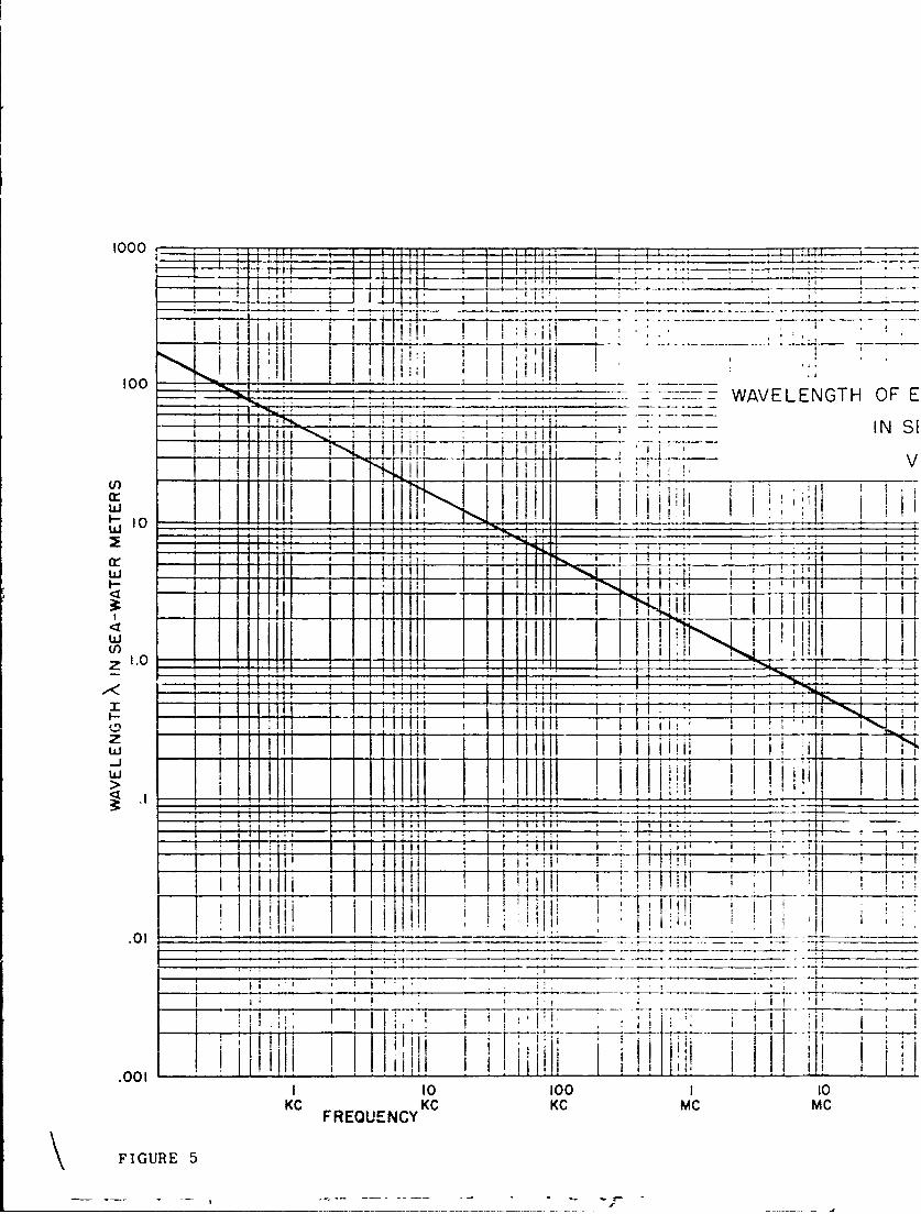
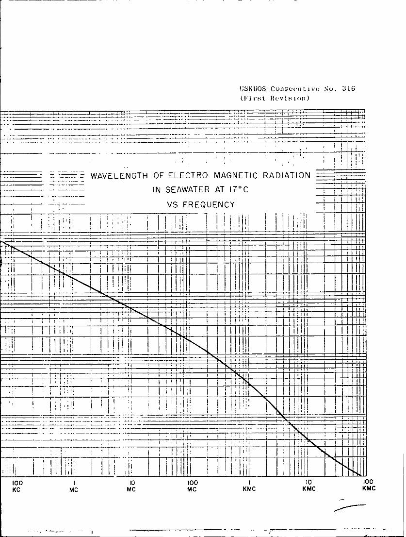
22. Curve 2 (figure 5) is a plot of wave length of
electromagnetic radiation in sea water. X 2 varies inverselyas the square root of frequency up to 100 Mc.
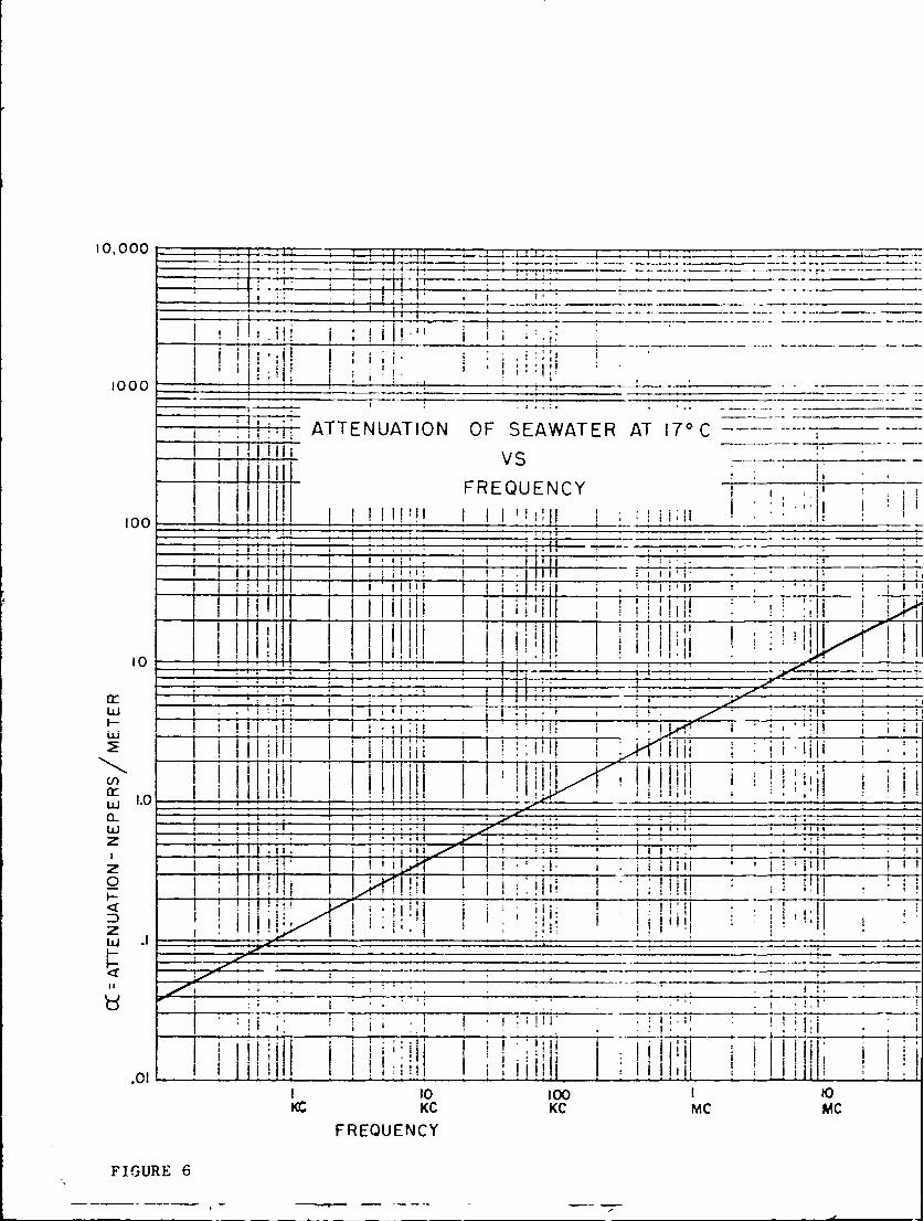
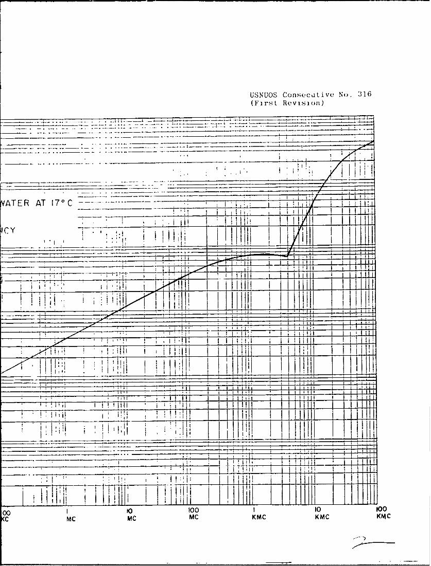
3. Curve 3 (figure 6) shows that the attenuationvaries directly as the square root of the frequency up to100 Mc. Of ac least passing interest is the notch in theregion between 3.5 and 4 kilo-megacycles. The depth of thenotch, measured from the local maximum at about 2 kmc, isat most 5 nepers per meter. (In db, this is 5 x 8.686 =43.4 db.) Since the level in this region is about 70 nepersper meter (608 db per meter), the percentage decrease is aminute 0.8 per cent. Beyond this valley, the curve risessharply to the imposing height at 100 kmcs of 4000 nepersper meter or 34,800 db per meter.
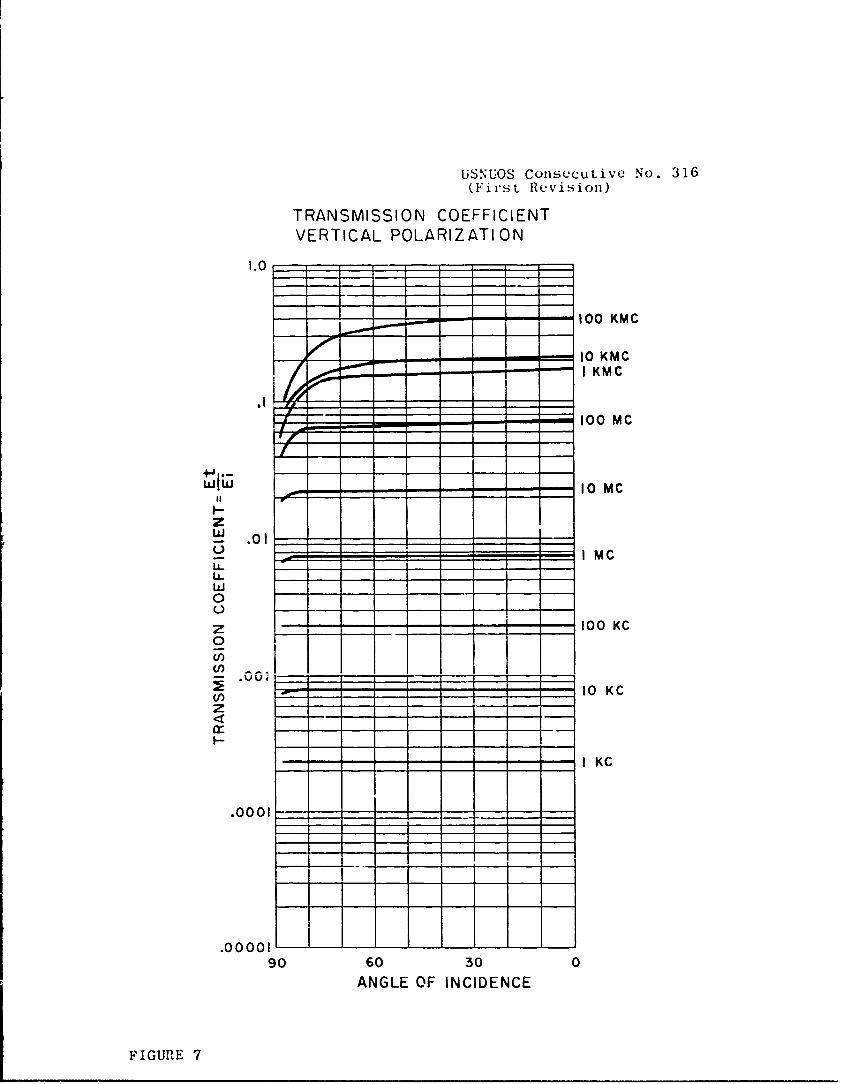
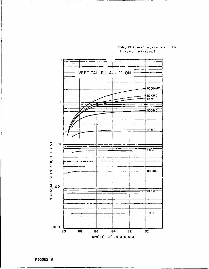
4. Curve 4 (figure 7) shows the variation of trans-mission coefficient with angle of incidence for verticalpolarization of the incident wave. For the lower frequen-cies shown, the transmission coefficient is practicallyindependent of angle of incidence for angles below 89.5'.The angles of refraction were always less than 6.5' for thevalues of chosen. For 10 kmc and below, the angles ofrefraction were always below 1'. Curves 5 and 6 (figures 8and 9) show transmission coefficient and the phase anglebetween the incident and refracted waves, plotted on anexpanded scale of angle of incidence between 80 and 90degrees.
8
_____ _ _______1
100 __ J1'i ~~h 110!
_..... . PHASE ANGLE -- -
-------- --4"
1.0 i, l11" -- _-
I
H
I 100
KC KC KC MC
FREQUENCY
FIGURE 4
ji2 t __ _ __
USNUOS Consecutive No. 316(First Revision)
__O _00K~
1-100 _
50w
=--NTRINSIC IMPEDANCE OF THE:SEA-WATER MEDIUM I_
10 100 1 10 100MC M C 'mc KMVC KMC
100_______ WAVELENGTH OF E
IN S1
1,- 10 _ _ _ _ _ _ _ _
wr
1.0 _ _ _ _
w I f
____________0 1_____ _______________
10t 100 10tKCFREQUENCYKCC m
\ FIGURE 5
USNUOS Consecutive No. 316(First Revision)
____ - -WAVELENGTH OF ELECTRO MAGNETIC RADIATION
IN SEAWATER AT 17 0 C
VS FREQUENCY
I j i-
- :1 -7 11__
_____ ____ _____ _ L.L.4.
100 110 10 1 1 100KC_ _ __ _ _ ___ ii 'Ij KMC IKhhI K
10,000 _ _ _ _ _.. ~ 4 ± 9~
_ _ ii j ji i l i i, i _ _ _ _ _ _ _ _ _ _ __•_ _,_ _ _ _
1000 ~ II________ __
_ ___, . '. ', ' I . " . . -.,
77.i~- ATTENUATION OF SEAWATER AT 170 C ..... _
I I i ii v;
FREQUENCY i; 9. i'I 0I [ IIii I ' : iI ! - ! iI: " ,
I l!iiiii ~ !i' I I i I! , I IIII - ' '"_ _ I
100 _ _ _ _ _ _ _ _ _ __ _ _ _ _ _ _ _ _ _ _
11i1 T1 I ''i i i i1T I I ~ Ti1ii ________ "i':'I I i I:' 'i'IIII I
-- J __0-I ..9i "' I . I ... .. .
Lii I '' : l I iI * * "' _ _ i 'i.; i i . . " ______
:i i i ! i i ,~i _______ _-_i____ • , Ji l iIHI'I! i I ' :1 I! _______ il _____
1 .0.. ''
1 10 10 1 to
I , !I' I .i9
. . . . .___. . ....______ __---_" ,_____, ,__,_."
I . . ' . . . . ! ' "* * I ~ I *:'9 .
.0- '~ Ii I I , ,111 K, i 1, i i i i '1 :
LI 10I OO I 10
KC KC KC MC MC
FREQUENCY
FIGURE 6
USNUOS Consecutive No. 316(First Revision)
S I i i
ATER AT 170 C . i
____,,__i___i,__i__i
!/__,_ _i -
i _______i
Ii. . iii ! !ii!liil I i' Ii
1c Y
4R.-
, i ! I ,
a a
.v i !
I
_______________ •_____________________
I I I I 111 1 I I I i I
I ' ' I:
! t i :' ' ! i i I I i i l
";. . .. ' , I !L i iJ l i i I ! i i.
______________. . ____, ___, , __ ________ i __ I ii I ' 'I i i i------ ------------- 1 4
00 to too I 10 to0
C MC MC MC KMC KMC KMC
USNUOS Consecutive No. 316(First Revision)
TRANSMISSION COEFFICIENTVERTICAL POLARIZATION
1.0
100 KMC
LL~j - - - - 10 KMC
zG .01 1 m0I MC
U-4
z 100 KC
C/)
10 KC
-IK
H
.0001
.00 00,I90 60 30 0
ANGLE OF INCIDENCE
FIGURE 7
USNUOS Consecutive No. 316
(.'irst Revision)
VERTICAL PU..A,,. ION
IQKMC
---- -- IOKMCI KMC
_ fl I0 MC
I-z .01w
Li.
z _____ ,ooc0
o I
U)2.001 "OK-
11KC
90 88 86 84 82 80
ANGLE OF INCIDENCE
FIGURE 8

USNUOS Consecutive No. 316
(First Revision)
PHASE ANGLE OF T.C. FOR
-:RT'CAL POLARIZATION
45~ 40 KC______ ______ ___100 IO KC
I MC
0 2z1iizII- t h 1 -t
z
I 100 KMC
0
L10 30
90 8 6 8z2 8
FIGR2
USNUOS Consecutive No. 316(First Revision)
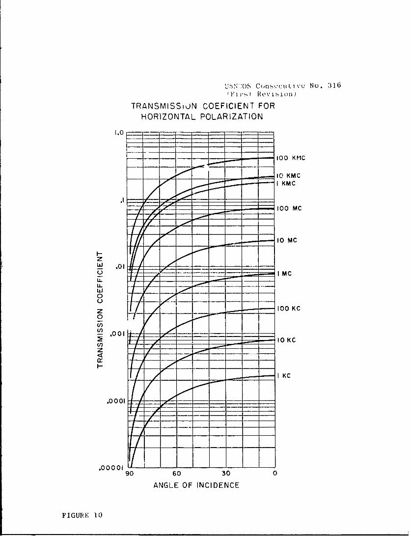
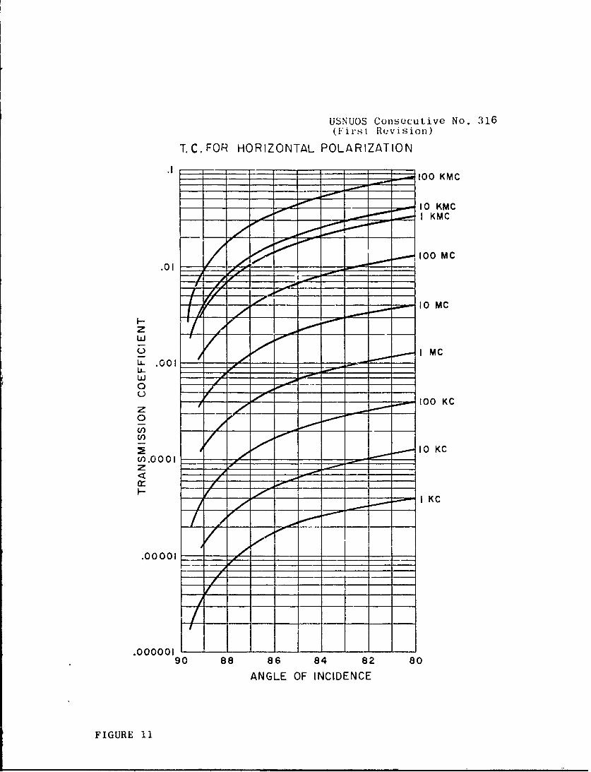
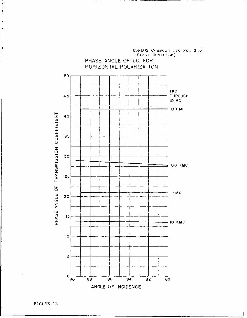
5. Curves 7, 8 and 9 (figures 10, 11 and 12) repeatthose of the preceding paragraph for horizontal polarizationof the incident wave. In this case, the transmission coef-ficient falls rather rapidly toward zero as the angle ofincidence increases. It should be noted that the points atzero angle of incidence, at corresponding frequencies, areidentical for both horizontal and vertical polarization.For a wave directed perpendicular to an interface, the senseof polarization is lost.
It is noted that as frequency increases the transmissioncoefficient incroases, as does also the attenuation withinthe sea water medium. In the r6kion of the frequency spec-trum, where we may expect to obtain 10 to 50 per cent ofthe incident field strength on the under side of the inter-face, the attenuation is so high that the signals areuseless. In the region where attenuation becomes morenearly reasonable, the losses through the interface becce'elarge.
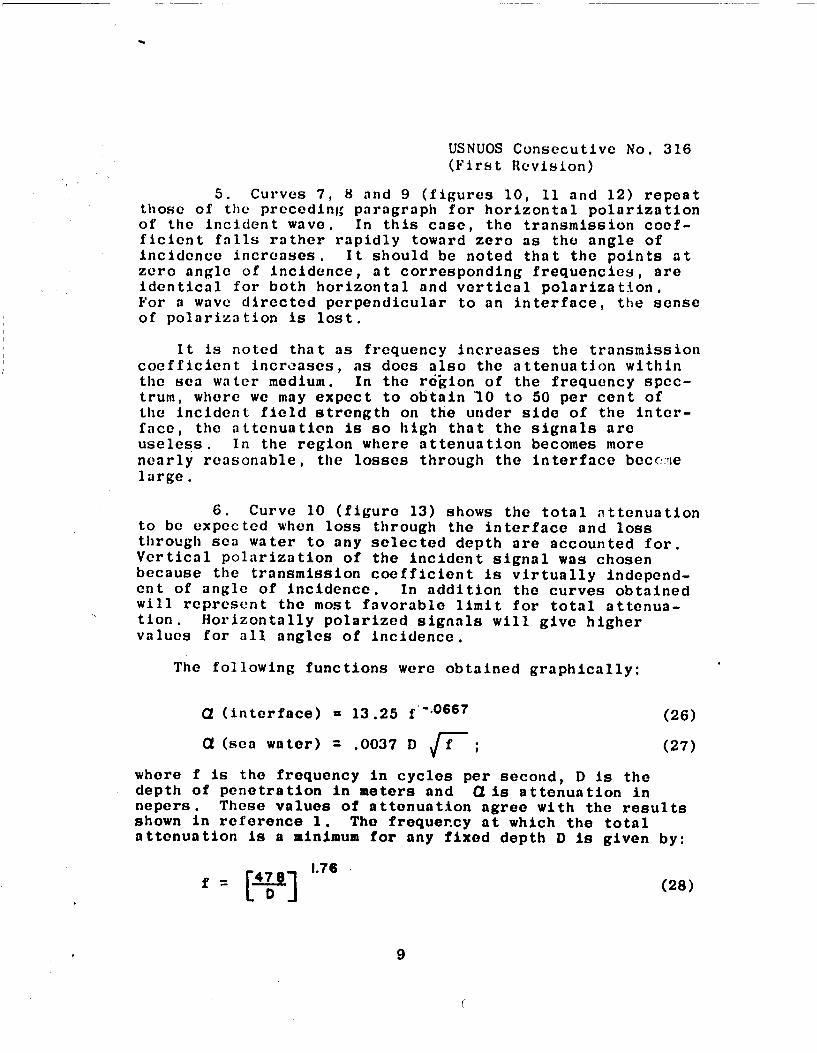
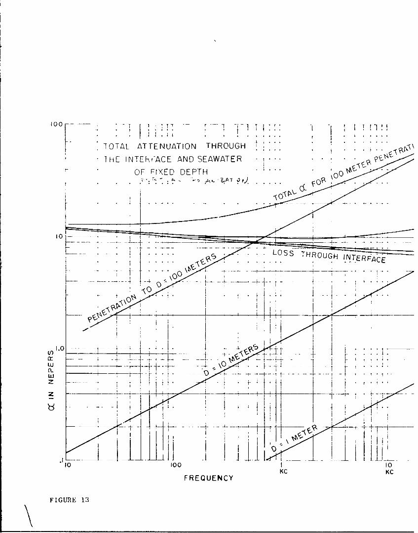
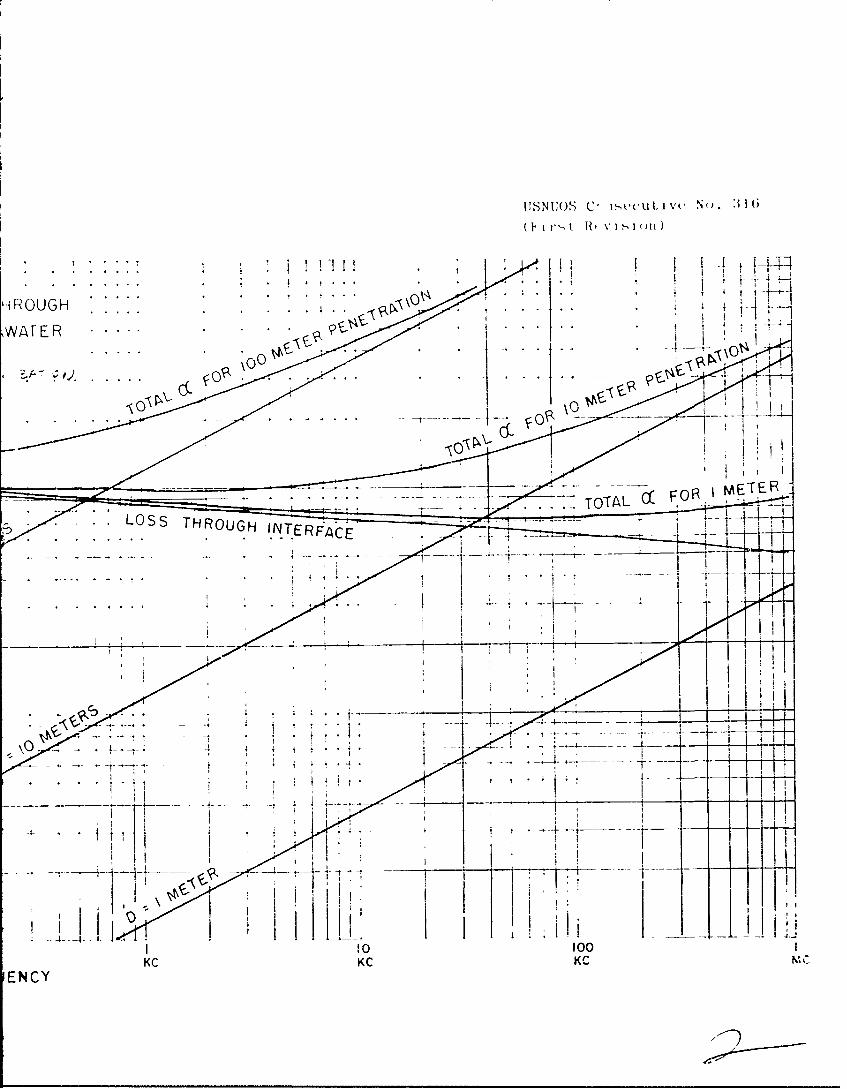
6. Curve 10 (figure 13) shows the total attenuationto be expected when loss through the interface and lossthrough sea water to any selected depth are accounted for.Vertical polarization of the incident signal was chosenbecause the transmission coefficient is virtually independ-ent of angle of incidence. In addition the curves obtainedwill represent the most favorable limit for total attenua-tion. Horizontally polarized signals will give highervalues for all angles of incidence.
The following functions were obtained graphically:
" (interface) = 13.25 f-. 0 6 6 7 (26)
" (sea water) - .0037 D -f; (27)
where f is the frequency in cycles per second, D is thedepth of penetration in meters and a is attenuation innepers. These values of attenuation agree with the resultsshown in reference 1. The frequency at which the totalattenuation is a minimum for any fixed depth D is given by:
[ r478) 1.76 (28)
9
U~5Nos onscu vcNo. *316
V -IRev ision)
TRANSMISSiuN COEFICIENT FORHORIZONTAL POLARIZATION
"0
100 MPC
10 MC
H-z
S.0IO I MC
w _
z [ _ 100 KC
(I)-. 001
___ 10 KC
_ _I KC
.0001
.0000,90 60 30 0
ANGLE OF INCIDENCE
FIGURE 10
USNUOS Consecutive No. 316(First Re(-visionl)
T.C. FOR HORIZONTAL POLARIZATION
.1 100 KMC
I0 KMC
10 KMC
.01 10M
ZZZ~EE10 MG
wO10 I MC
U~.001
w0
-- 7 10 0_ KC
10 KC
I0 KG
.00001
.0000011 - - ~ ~ --
90 88 86 84 82 80
ANGLE OF INCIDENCE
FIGURE 11
USNUOS Consecutive No. 316(I:'st R vision)
PHASE ANGLE OF T.C. FORHORIZONTAL POLARIZATION
50 iR
i~ IKC
5 THROUGH
10 M
z 40Lii
35--- - --- "b_
0wL 3.50
z0&i 30
:; 100 KMC
z
o 0 I i KMCI -i I
w I KMC- - -
_j 20 -
z
-r _ y - 10 KMC
10
5
90 88 86 84 82 80
ANGLE OF INCIDENCE
FIGURE 12
TAL ATTENUATION THROUGH
THE INTEkiKACE AND SEAWATER*
OF FIXED DEPTH
. ... OSTHROUGH I N ERFAC
1.0
w -_
KC K
FREQUENCY
FIGURE 13
USNUOS C> S iv N .31-
H-ROUGH . .-
WAFER
FOR METER
LUSTHROUGH INTERFAb~.~
0 10
KG KC K-
ENCY
USNUOS Consecutive No. 316(First Revision)
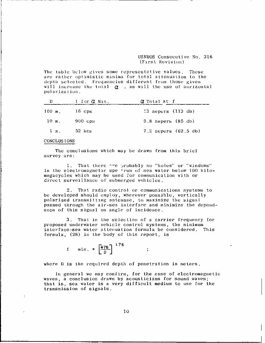
The table below gives some representative values. Theseare rather optimistic minima for total attenuation to thedepth selected. Frequencies different from those givenwill increase the total a , as will the use of horizontalpol ariza I ion.
D 1 1o1t A MIn. Q Total at f
100 Il. 16 cps 13 nepers (113 db)
10 m. 900 cps 9.8 nepers (85 db)
1 m. 52 kcs 7.2 nepers (62.5 db)
CONCLUS IONS
The conclusions which may be drawn from this briefsurvey are:
1. That there -'-e -robably no "holes" or 'windows"in the electromagnetic spe 1rum of sea water below 100 kilo-megacycles which may be used for communication with ordirect surveillance of submerged vhicles.
2. That radio control or communications systems tobe developed should employ, wherever possible, verticallypolarized transmitting antennae, to maximize the signalpassed through the air-sea interface and minimize the depend-ence of this signal on angle of incidence.
3. That in the selection of a carrier frequency forproposed underwater vehicle control systems, the minimuminterface-sea water attenuation formula be considered. Thisformula, (28) in the body of this report, is
f min. = 1.76
where D is the required depth of penetration in meters.
In general we may confirm, for the case of electromagneticwaves, a conclusion drawn by acousticians for sound waves;that is, sea water is a very difficult medium to use for thetransmission of signals.
10
USNUOS Consecutive No. 316
(First Revision)
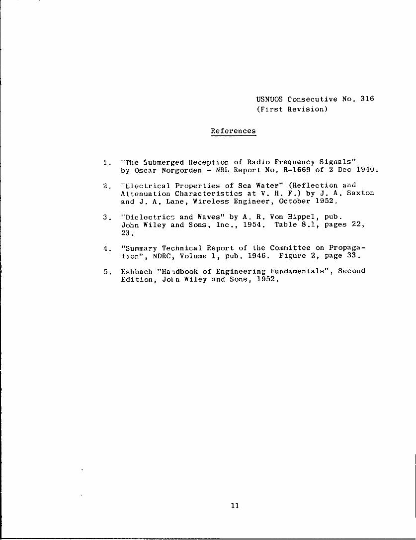
References
1. "The Submerged Reception of Radio Frequency Signals"
by Oscar Norgorden - NRL Report No. R-1669 of 2 Dec 1940.
2. "Electrical Properties of Sea Water" (Reflection andAttenuation Characteristics at V. H. F.) by J. A. Saxton
and J. A. Lane, Wireless Engineer, October 1952.
3. "Dielectricz and Waves" by A. R. Von Hippel, pub.John Wiley and Sons, Inc., 1954. Table 8.1, pages 22,23.
4. "Summary Technical Report of the Committee on Propaga-
tion", NDRC, Volume 1, pub. 1946. Figure 2, page 33.
5. Eshbach "Ha-dbook of Engineering Fundamentals", SecondEdition, Join Wiley and Sons, 1952.
11
USNUOS Consecutive No. 316
(First Revision)
DISTRIBUTION LISTNo. of
A ddri- ' Copies
Chief of Naval Operations (OEG) 1Navy )epar tment~\:~h ingon 25, 1). C.
Chief of Naval Operations 1We,,-apons Systumns Evaluation GroupNavy DepartmentWashington 25, D. C.
Chief, Bureau of Naval Weapons (R1) 1Navy DepartmentWashington 25, D. C.
Chief, Bureau of Ships 1Navy DepartmentWashington 25, D. C.
National Research Council 1Committee on Undersea WarfareWashington 25, D. C.
Commanding Officer and Director INew London Development Detachment
Operational Development ForceU. S. Navy Underwater Sound LaboratoryFort TrumbullNew London, Conn.
Commanding Officer and Director 1David W. Taylor Model BasinWashington 7, D. C.
Commanding Officer and Director 1U. S. Navy Electronics LaboratorySan Diego 52, Calif.
Commanding Officer IU. S. Naval Air Development CenterJohnsville, Pa.
Commander 3U. S. Naval Ordnance LaboratoryWhite OakSilver Spring 19, Md.
USNUOS Consecutive No. 316
(First Revision)
DISTRIBUTION LIST (Contd.)No. of
A d d r e ec Copies
Colm iia In der rU. S. Naval Ordnance Test StationChina Lake, Calif.(Technical I)irector)
Comma nder (Code 753)U. S. Naval Ordnance Te.t StationChina Lake, Calif.(Technical Library)
C ommn 11a n d rU. S. Naval Ordnance Test, Station
Pasadena Annex3202 East Foothill BoulevardPasadena 8, Calif.(Pasadena Annex Library)
Oflice of Naval ResearchNavy DepartmentWashington 25. D. C.
DirectorU. S. Naval Research LalboratoryWashington 25, 1). C.
)i rectorOrdnance Research Laboratory
Penn State UniversityUniversity Park, Pa.
1) i rec torWoods Hole Oceanographic InstitutionWoods Hole, Mass.
Scripps Institution of Oceanography(Marine Physics Laboratory)
LaJolla, Cal if.
Dirt-ctor, Applied l-hysics LaboratoryUniversity of WashingtonSeattle, Wash.
Hudson LaboratoryColumbia UniversityDobbs Ferry, N. Y.
NAVY-DPPO, INI), Newport, R. I.