Embed Size (px)
Citation preview
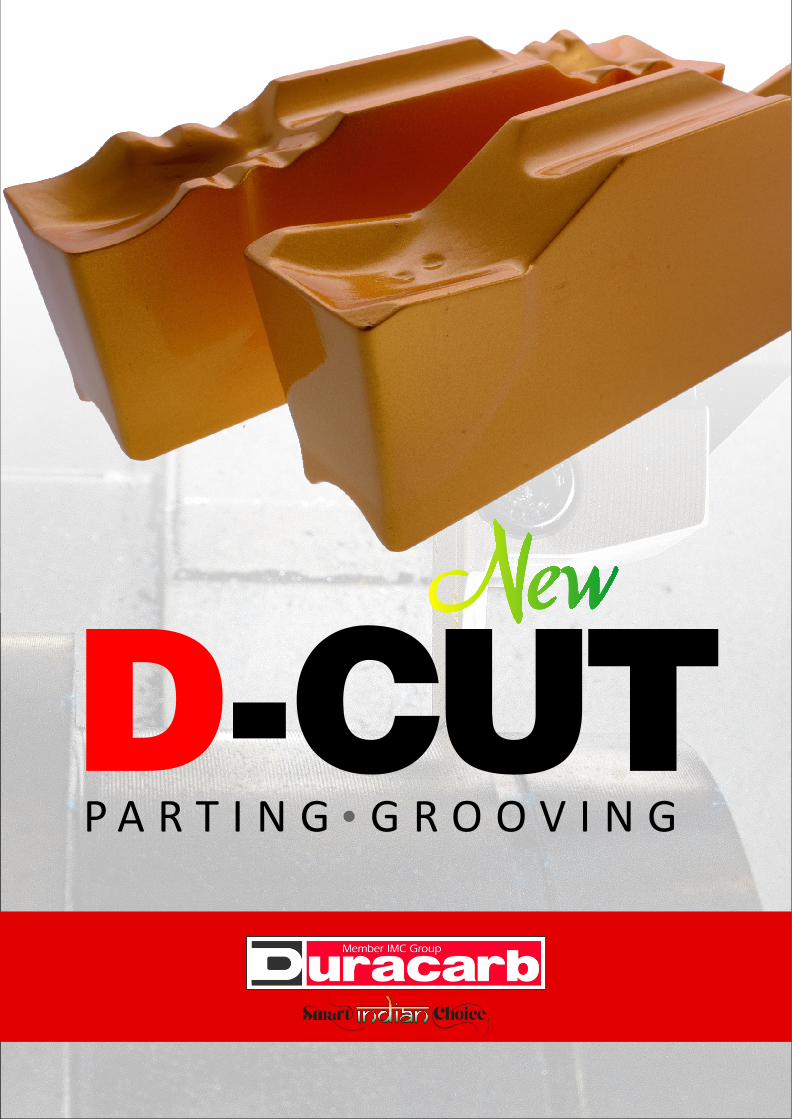
D-CUTP A R T I N G G R O O V I N G
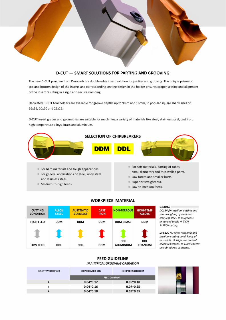
D-CUT — SMART SOLUTIONS FOR PARTING AND GROOVING
SELECTION OF CHIPBREAKERS
GRADESDC154 for medium cutting and semi-roughing of steel and stainless steel. Toughness enhanced grade TiCN.
PVD coating.
DP5320 for semi-roughing and medium cutting on all kinds of materials. High mechanical shock resistance. TiAlN coated on sub-micron substrate.
ll
l
ll
WORK PIECE MATERIAL
INSERT WIDTH(mm)
2
3
4
CHIPBREAKER DDL
FEED (mm/rev)
CHIPBREAKER DDM
HIGH FEED DDM DDM DDMDDM BRASSDDM
LOW FEED DDL DDLDDL
TITANIUMDDL
ALUMINIUM
CUTTING CONDITION
ALLOY STEEL
AUSTENITICSTAINLESS
HIGH-TEMPALLOYS
CAST IRON
NON-FERROUS
DDM
FEED GUIDELINE IN A TYPICAL GROOVING OPERATION
0.04~0.12
0.04~0.16
0.04~0.18
0.05~0.18
0.07~0.25
0.09~0.35
For soft materials, parting of tubes,
small diameters and thin-walled parts.
Low forces and smaller burrs.
Superior straightness.
Low-to-medium feeds.
l
l
l
l
For hard materials and tough applications.
For general applications on steel, alloy steel
and stainless steel.
Medium-to-high feeds.
l
l
l
DDLDDM
The new D-CUT program from Duracarb is a double edge insert solution for parting and grooving. The unique prismatic
top and bottom design of the inserts and corresponding seating design in the holder ensures proper seating and alignment
of the insert resulting in a rigid and secure clamping.
Dedicated D-CUT tool holders are available for groove depths up to 9mm and 16mm, in popular square shank sizes of
16x16, 20x20 and 25x25.
D-CUT insert grades and geometries are suitable for machining a variety of materials like steel, stainless steel, cast iron,
high temperature alloys, brass and aluminium.
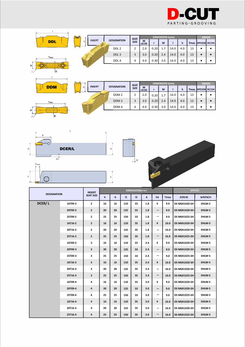
INSERT
INSERT
Tmax DP5320 DC154
GRADE
13
13
13
W+0.05 r M l h
DESIGNATIONSEATSIZE
DIMENSION (mm)
DDL 2 2 2.0 0.20 1.7 14.0 4.0
3 3.0 0.20 2.4 14.0 4.0
4 4.0 0.30 3.0 14.0 4.0
DDL 3
DDL 4
13
13
13
Tmax DP5320 DC154DESIGNATION
SEATSIZE
DDM 2 2 2.0 0.20 1.7 14.0 4.0
3 3.0 0.20 2.4 14.0 4.0
4 4.0 0.30 3.0 14.0 4.0
DDM 3
DDM 4
W+0.05 r M l h
DCER/ L
DIMENSION(mm) SPARESINSERT
SEAT SIZESCREW
DS M6X1X20-SH DHLW-5
DHLW-5
DHLW-5
DHLW-5
DHLW-5
DHLW-5
DHLW-5
DHLW-5
DHLW-5
DHLW-5
DHLW-5
DHLW-5
DHLW-5
DHLW-5
DHLW-5
DHLW-5
DHLW-5
DHLW-5
DS M6X1X20-SH
DS M6X1X25-SH
DS M6X1X20-SH
DS M6X1X20-SH
DS M6X1X25-SH
DS M6X1X20-SH
DS M6X1X20-SH
DS M6X1X25-SH
DS M6X1X20-SH
DS M6X1X20-SH
DS M6X1X25-SH
DS M6X1X20-SH
DS M6X1X20-SH
DS M6X1X25-SH
DS M6X1X20-SH
DS M6X1X20-SH
DS M6X1X25-SH
h h4 Tmaxb l1 l2 A WRENCH
16T09-2
16T09-4
20T09-4
25T09-4
16T09-3
20T09-3
25T09-3
20T09-2
25T09-2
16T16-2
16T16-3
16T16-4
25T16-4
20T16-4
20T16-3
25T16-3
20T16-2
25T16-2
2 16 16 33 1.8 9.0
9.0
9.0
16.0
16.0
16.0
9.0
9.0
9.0
16.0
16.0
16.0
9.0
9.0
9.0
16.0
16.0
16.0
4
—
—
4
—
—
4
—
—
4
—
—
4
—
—
4
—
—
110
20 20 33 1.8125
20 20
20 20
20 20
20 20
20 20
25 25 33 1.8
33
33
33
33
33
33
35 1.8
35 1.8
2.4
2.4
2.4
2.4
2.4
2.4
3.0
3.0
3.0
3.0
3.0
3.0
35 1.8
35
35
35
35
35
35
150
110
125
150
110
125
150
110
125
150
110
125
150
110
125
150
25 25
25 25
25 25
25 25
25 25
16 16
16 16
16 16
16 16
16 16
2
2
2
2
2
3
3
3
3
3
4
4
4
4
4
4
3
DESIGNATION
D-CUTP A R T I N G G R O O V I N G
DDL
DDM
DCER/L
GRADEDIMENSION (mm)
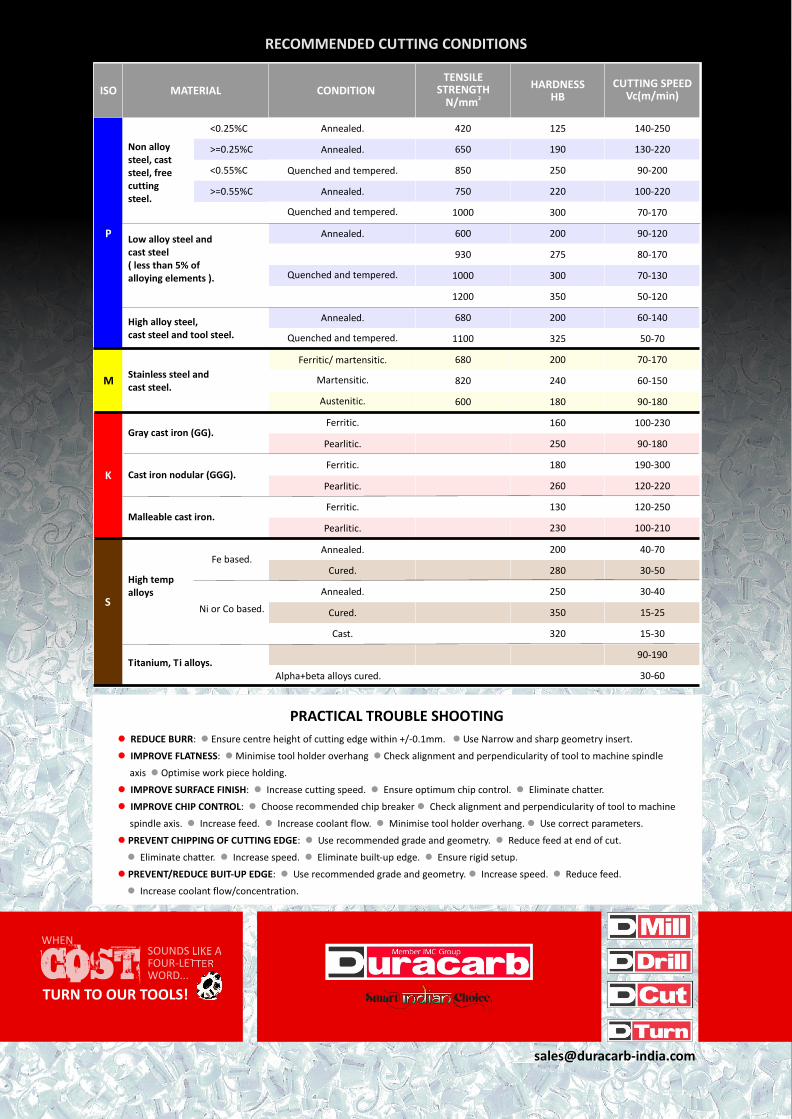
RECOMMENDED CUTTING CONDITIONS
PRACTICAL TROUBLE SHOOTING
SOUNDS LIKE A FOUR-LETTER WORD...
EH NW
TURN TO OUR TOOLS!
REDUCE BURR: Ensure centre height of cutting edge within +/-0.1mm. Use Narrow and sharp geometry insert.
IMPROVE FLATNESS: Minimise tool holder overhang Check alignment and perpendicularity of tool to machine spindle
axis Optimise work piece holding.
IMPROVE SURFACE FINISH: Increase cutting speed. Ensure optimum chip control. Eliminate chatter.
IMPROVE CHIP CONTROL: Choose recommended chip breaker Check alignment and perpendicularity of tool to machine
spindle axis. Increase feed. Increase coolant flow. Minimise tool holder overhang. Use correct parameters.
PREVENT CHIPPING OF CUTTING EDGE: Use recommended grade and geometry. Reduce feed at end of cut.
Eliminate chatter. Increase speed. Eliminate built-up edge. Ensure rigid setup.
PREVENT/REDUCE BUIT-UP EDGE: Use recommended grade and geometry. Increase speed. Reduce feed.
Increase coolant flow/concentration.
l
l
l
l
l
l
l l
l l
l
l l l
l l
l l l l
l l
l l l l
l l l
l
MATERIALISO CONDITIONTENSILE
STRENGTH2N/mm
HARDNESSHB
CUTTING SPEEDVc(m/min)
Non alloy steel, cast steel, freecutting steel.
High temp alloys
Low alloy steel and cast steel( less than 5% of alloying elements ).
High alloy steel, cast steel and tool steel.
Stainless steel and cast steel.
Gray cast iron (GG).
Cast iron nodular (GGG).
Malleable cast iron.
Titanium, Ti alloys.
Annealed.<0.25%C
<0.55%C
>=0.25%C
>=0.55%C
420 125 140-250
130-220
100-220
100-230
40-70
190-300
30-40
120-220
15-25
120-250
15-30
100-210
90-190
30-60
90-200
70-170
90-120
80-170
70-130
70-170
60-150
90-180
90-180
30-50
50-120
60-140
50-70
650 190
600 200
600 180
180
250
260
350
130
320
230
160
200
250
280
680 200
680 200
930 275
850 250
820 240
750 220
1000 300
1000 300
1200 350
1100 325
Annealed.
Quenched and tempered.
Quenched and tempered.
Quenched and tempered.
Martensitic.
Austenitic.
Quenched and tempered.
Annealed.
Annealed.
Annealed.Fe based.
Ni or Co based.
Ferritic/ martensitic.
Ferritic.
Ferritic.
Annealed.
Ferritic.
Cast.
Pearlitic.
Cured.
Pearlitic.
Cured.
Pearlitic.
Alpha+beta alloys cured.
Annealed.P
M
K
S