Embed Size (px)
Citation preview

D CL I! R! 0 CARBURATORI
A 1.1 to the choice, setting and use of tapered-needle motorcycle carburettors
•
_WOGc:
rofW~ """''''''' .~> . .!.~ ....
n .1I1"~"''to' ,....._~.. .~ ... ft'
I W4~ ~. I~'" ,~~ ~,.~ -I I f' 7l YiW' JII.IfM' •• .. 1\ r \ \II ,~,~.-. ,\ \ \ 11_ Illto: ,..r«:::::3 '<\ '" ' ..... ' / , III~""~ ... :k. > Ir l' II~I .,., oI!!NI' ~,11!:1f c- NtH' ~'~ I~"': .,'51 Ih ""''''5'5 So' I • pm_IE" ... ,_ ..... .. ~ I • ~ .,.,,~ ., _
I •• "'" --...,_ I • ..- 1. •• _ ... '<! ... _oc:: If. I ..
....... • ' ---..¥ ~' .... --
=

appendix
1
2
2.1
2.2
2.3
2.4
2.5
2.6
3
3.1
3.1.1
3.2
3.2.1
FUNCTIONS OF THE CARBURETTOR ........ " .... .. ....... ...... .. . .. .. . FEATURES ............. ......... ........... ..•...•. . . . .••......•..•...
Carburettor diagram and principal parts .....••. • •. . •. . . . • _ ..•..... • • . • • . ..
Operating ranges ........ . ......... . .......•... •..........• , .. , , , • . . •.. .
Installation angles ...... • ............. • ... •. ....... ..•. , .•...... • ..•...
Engine connections .. . .... • • _ . •• .. .... • ...•. • • • • ••• • •• • •• • . . •.•••. • • . ..
Air Intakes . .. ... .. .. . ................. . ........ ........ ... . .... . ..•...
Construction materials .. . ................ . .......... .. ......... , ....•...
OPERATION,SELECTION OF CORRECT PARTS, TUNING AND USE .....• • ...
The venturi effect ...... ............................................ .• ...
Selection of the correct carburettor size ......•.... , . .. ..•.. . •... . . .• ..•. ..
Fuel supply system ... . ....................•..•...•...•.. < • • •••••• • • • •••
Selection of the needle valve size ...... . . • ...•. . • •. •• . . •• •• . • .••.•••.••...
Pag.
3
4
4
4
5
5
6
6
6
6
7
• •
3.2.2 Select ion of the float ..... ........ .. _ •• •• • • , . • •• • • • • • . • • . . . • . . • . . . • . . • . . . 9
3.3 Starting from cold ., .,., ....... , ....... ,........ ...... . ............. . ... 10
3,3.1 Independent staring circuit .......... , .. . ,..... ........ . ...... . .......... 11
3.3.2 Selection of starter emulsion tube and starter Jet .. . . .• • . .• • . .. , .•• . .• . , . . ... 11
3.3.3 The flood ing plunger starting device ................ •• ..•• "., . •• . , . ,.. .. .. 12
3.4 Idle systems . . . . . . . . . . . . . . . . . . . . . . . . . . . . . . . . . . . . . • . . . • . . • . . . • . . . . . . . . . . 12
3.4.1 Setting the idle with a mixture adJusting-screw .. ......•...•....... ... _ . . • . . . 13
3.4.2 Setting the idle with an air adjusting-screw .. .. ... ....•... • ... _ . . . . . . • . . • . . . 13
3.4.3 Selection of the correct size of idle jet .. . ..... . ..•...•... • ......•.. • •..•... 14
3.5 Progression system ....... .... . . .................. ..... .. . , •• •• •• , • • . . . 14
3.6 Full throttle operation . .... ...... , .. .. ... .............. ... . ". ... ... .. ... 15
3.6. 1 Full throttle system as usually used on two·stroke engines ... ..•. .....•..•... 15
3.6.2 Full throttle system as usually used on four-stroke engines .. .. .• ......•.. • ... 16
3.6.3 Selection of the throttle valve cutaway . . . . . . . . . . . . . . . . . . . . . . • • • • . . . • • . • • . . . 16
3.6.4 Selection of the tapered needle .. . . . . . . . . . . . . . . . . . . . . . . . • . .. .. . . .. . • . .. . . . 17
3.6.5 Selection of the correct size main Jet ...... . .••... •.. .• '.' . . . . • . . • . . . • . . • . . . 17
3.7 Acceleration mechanism ........... ...... .... ..•. .. • ... •... . ..•.. • .. . ... 18
3.7.1 Diaphragm accelerator pump . . ......... .... . ... ...... ..... . ... . ... . ..... 19
3.7.2 Selection of correct pump cam and pump Jet ...... . ... ...... .... . . •......•. . 19
3.7.3 Piston type accelerator pump ....... ........... .... ... .. .. ............... 20
4 MULTY·CYLINDER ENGINES . .. .............. ... ............... . ......... 20
4.1 Idle tuning and adjustment ....... ... . ..... . ,....... ..... ... . .. . ... . .... . 21
5. FACTORS WHICH CAN ALSO AFFECTTHE CARBURATION .....•.... ..• ..... 22
5.1 Changes of fuel .....................•....................••..•... . ..... 22
5.2 Changes In atmospheric pressure and air temperature .....••. .• •.•• •• ••.• ... 22

1 FUNCTIONS OF THE CARBURETTOR
The main carburettor functions are:
- To form a proper homogeneous inflammable mixture of fuel and air - To supply the engine with varying amounts of this mixture
The fuel-air mixture Is formed through vapourlslng and, by uniformly spraying fuel into the airstream or at least by atom Ising it Into very small droplets.
Atomlsat ion takes place in this way: liquid fuel from the atomiser nOlzle meets the flow of air which carries it , ~roken into very fine droplets, to the combustion chamber.
We have spoken of a «proper» mixture because the mixture strength, defined as the amount of air in weight mixed with a fuel unit of weight , must have a precise value ,i e it must be wi th in the limits of Inflammability so that the mixture can be eaSily ignited by the spark In the combustion chamber .
Inflammmability limits for commercial petrol are: 7:1 (rich limit Ie. 7 kgs of air and 1 kg of petrol) , down to 20:1 (lean limit ie: 20 kgs of air and 1 kg of petrol) .
To obtain optimum combustion between these inflammability limits, a value very close to the so-called stoiciometric value is needed ie. about 14.5-15.0 kgs of air to 1 kg of petrol.
A stolclometrlc mixture ratio is one which ensures complete combustion of fuel with onl y the formation of w.ater and carbon dioxide.
The stolclometrlc mixture ratio depends on the kind of fuel used, so If the fuel Is changed, this fuel-air ratio will also change (see chapter 5.1) .
The selection of the fuel-air ratio is therefore very important both for engine performance and for exhaust emission levels.
The throttle valve (usually a f lat or piston-type gate valve, also called a slide) is the main part by which the engine is tuned ie. the engine power output is varied by controlling the amount of mixture being drawn into the cylinder .
During bench tests ,the engine is usually run In top gear in two characteristic conditions: full throttle and part throttle .
The full throttle test simulates conditions for a vehicle on a progressive climb with the throttle wide open .
In the bench test, this condition Is reproduced by running the engine with the throttle fully open ; from this maximum horsepower condition , the engine Is braked at various speeds and the specific power and consumption figures are taken .
The part throttle test simulates the conditions for vehicle on a level road at varying speeds.
On the test bench , this condition is simulated by running the engine again from the maximum engine power conditions , but progressively closing the throttle valve of the carburettor.
At various speeds, specific power and consumption figures are taken again .
3
4
2.FEATURES
2.1 Carburettor diagram and principal parts
Itg.1
2.2 Operating ranges . Scheme of phases while running
Ilg.2
1· Ilr In like . 2 -'hroille vltve 3 "Ipered nMdle 4· Ilomls.r Ind needlljel S· mlln je' 8· s'arllng dlvlee 1- venlurl 8 - Idle lpeed "juillng-screw ,I. Idll mlxlure Idjuillng-scrlw
10 'lllrlerje' "-Idleje' 12 - 1101' chember venl 13 -Iuellnlel banjo union 14 _ nMdle vl lve lS -11011 18 -11011 chlmber
mlln jillion.
jet and Ihrottle slide cullwlY
I
Figure 2 shows the section of a ventu ri according to the operating periods regulated by the throttle valve opening. In every phase of operation, it Is possible to vary and select the 'opti mum setting.
in the IC A .. · Idle stage, the Idle ci rcuit and Id le adjustment Is set with the mixture screw and idle-speed screw.
In the ICe .. progression phase, fuel mixture delivery from the idle hole is steadily replaced by mixture delivery from the progression hole, drawing emulsion mixture from the Idle ci rcui t, and In this range , choosing the correct idle jet and throttleslide cutaway Is necessary. The throttle valve cutaway slightly affects the carburat lon up to about half tht:ottle .
In the IC C .. high-speed per iod, mixture delivery from the Idle circuit anp from the progression hole is replaced by mixture from the main circu it and selection of both the atomiser and the tapered needle should then be made.
In the IC o lI period of full throttle and, with all the circuits of the earlier periods operating correctly , the size of the main jet is now final ly selected .
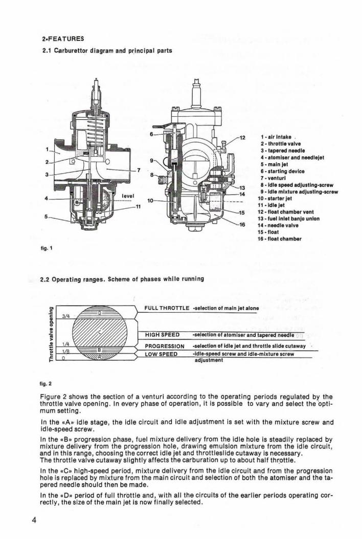
2.3 Installation angles
The tapered-needle-type carburettors with concentric, central float chambers have a horizontal main barrel and can be mounted up to a maximum incl ination of 40· from the horizontal (figure 3).
For applicatioFls on motocross and trials engines, etc, this Inclination should be 30· or less .
J __ L .nglne conn.cllon ,Ide
fig . 3
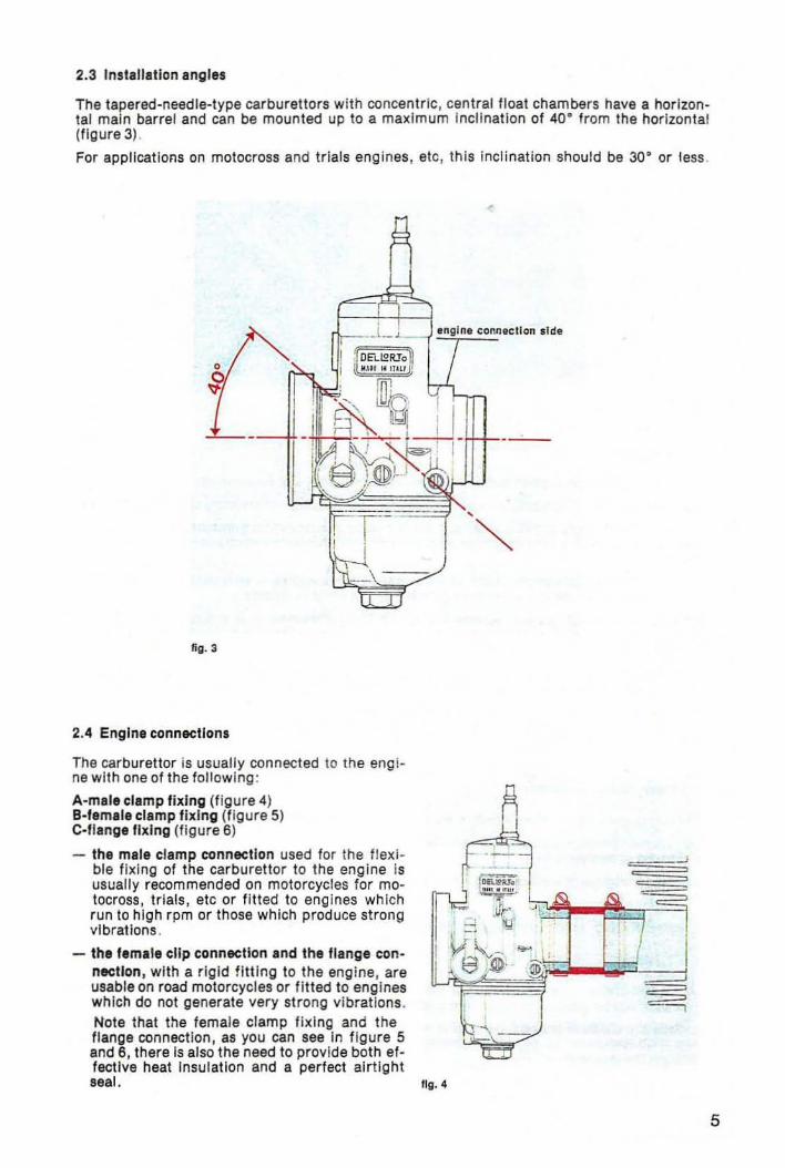
2.4 Engine connections
The carburettor is usually connected to the engine with one of the follow ing :
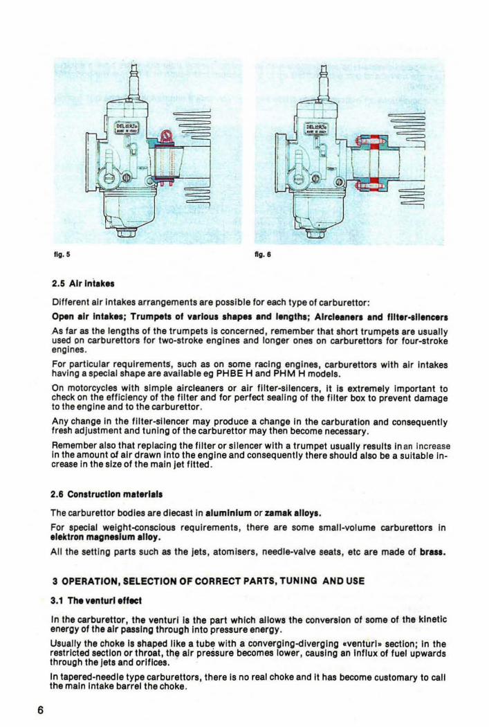
A-male clamp fixing (figure 4) B-'emale clamp fixing (figure 5) Coffange fixing (figure 6)
- the male clamp connection used for the f lexible f ixing of the carburettor to the engine is usually recommended on motorcycles for motocross, trials , etc or fitted to engines wh ich run to high rpm or those which produce strong vibrations .
- the lem.le clip connection and Ihe Ilange con nection, with a rigid fitting to the engine, are usable on road motorcycles or fitted to engines which do not generate very strong vibrations. Note that the female clamp fixing and the flange connection, as you can see in figure 5 and 6, there is also the need to provide both effective heat Insulation and a perfect airtight seal . Ilg.4
5
6
fig. 5 fig. I
2.5 Air Intlk.s
Different air Intakes arrangements are possible for each type of carburet tor:
Open Ilr Intlk.s; Trumpets of vlrlous shapes Ind lengths: Alrel.ln.rs and fIIt.r·sll.neers
As far as the lengths of the trumpets Is concerned, remember that short trumpets are usually used on carburettors for two-stroke engines and longer ones on carburettors for four-stroke engines.
For particular requirements, such as on some racing engines, carburettors with air Intakes having a special shape are available eg PH BE Hand PHM H models.
On motorcycles with simple alrcleaners or air filter-silencers . It Is extremely Important to check on the efficiency of the filter and for perfect sealing of the filter box to prevent damage to the engine and to the carburettor .
Any change In the filter-silencer may produce a change In the carburation and consequently fresh adjustment and tuning of the carburettor may then become necessary.
Remember also that replaCing the filter or silencer with a trumpet usually results Inan Increase In the amount 01 air drawn Into the engine and consequentry there should also be a suitable increase In the size of the main jet fitted .
2.6 Construction mlt.rlals
The carburettor bodies are dlecast in Ilumlnlum or umlk .IIoys.
For special welght-consclous requirements , there are some small-volume carburettors In ,I.ktron mlgnulum Illoy.
All the sett ing parts such as the jets, atomisers. needle-valve seats, etc are made of bras ••
3 OPERATION, SELECTION OF CORRECT PARTS, TUNINQ AND USE
3.1 Th. yenturl.fteet
In the carburettor, the venturi Is the part which allows the conversion of some of the kinetic energy of the air passing through Into pressure energy.
Usually the choke Is shaped like a tube with a converglng-dlverglng .venturl. section; In the restricted section or throat, the air pressure becomes lower, causing an Influx of fuel upwards through the jets and orifices.
In tapered-needle type carburettors, there Is no real choke and It has become customary to call the main Intake barrel the choke.
The throttle slide is fitted in the main barrel and fuel is delivered by the various circuits during the different operating periods.
It is very important that the carburettor supplies a fuel-air mixture which rema ins constant during the changes in throttle opening and under the different load conditions of the motorcycle engine .
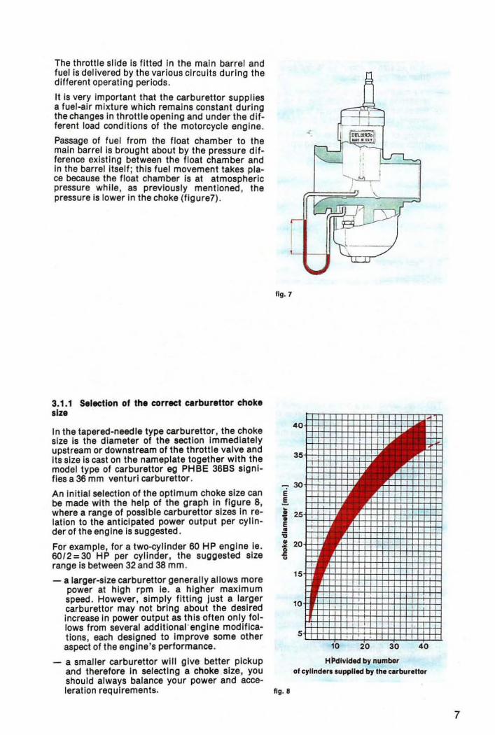
Passage of fuel from the float chamber to the main barrel Is brought about by the pressure d ifference existing between the float chamber and in the barrel itself ; this fuel movement takes place because the float chamber Is at atmospheric pressure while, as previously mentioned , the pressure is lower In the choke (flgure7) .
3.1.1 Selection of the correct ClrbureUor choke size
In the tapered-needle type carburettor, the choke size Is the diameter of the section immediately upstream or downstream of the throttle valve and Its size Is cast on the nameplate together with the model type of carburettor eg PH BE 36BS signifies a 36 mm venturi carburettor .
An initial selection of the optimum choke size can be made with the help of the graph in figure 8, where a range of possible carburettor sizes In relation to the anticipated power output per cylinder of the engine Is suggested .
For example, for a two-cyllnder 60 HP engine ie. 60 / 2=30 HP per cylinder , the suggested size range Is between 32 and 38 mm .
- a larger-size carburettor generally allows more power at high rpm Ie. a higher maximum speed. However, simply fitting just a larger carburettor may not bring about the desired Increase In power output as this often only follows from several additional ' engine modifications, each designed to Improve some other aspect of the engine's performance.
l I
l L- __
Ilg. 7
- a smaller carburettor will give better pickup Hl'dlvlNd by number and therefore in selecting a choke size, you ofeylinden.uppll«lbylnec.rbur,Uor should always balance your power and acce-leration requirements. fig. 8
7
8
- usually in conversions an increase in the carburettor size also requires an Increase In the main jet size of about 10 % for each 1 mm Increase in the choke size, without changing the other setting parts. '
- on a modified engine, whenever you require a carburettor larger than the or iginal , It Is preferable to use one which' has already been set up for a similar engine Ie. an eng ine having the same operation (two or four stroke) , a similar power output and similar cylinder displacement , In order to have a good comparable base for subsequent tun ing .
- tuning of racing engines is best carried out on the racing circuit with well run-in engines which are thoroughly warmed up .
3.2 FuellYltem
First of all, ensure that , with the engine running, fuel flows continuously from the tank to the carburettor as vibrations from the engine or from the road surface could reduce fuel flow .
It Is therefore advisable to use fuel taps and pipes of adequately-large size.
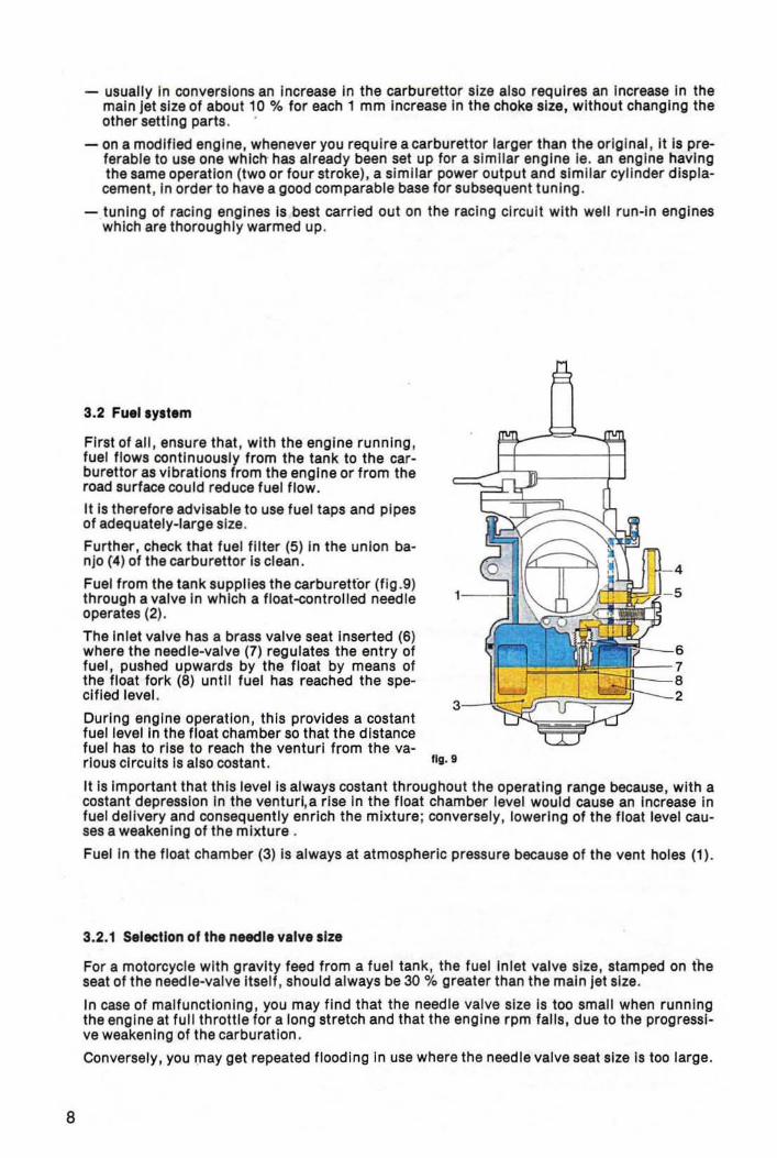
Further, check that fuel filter (5) in the union banJo (4) of the carburettor Is clean .
Fuel from the tank supplies the carburettor (fig .9) through a valve In which a float-controlled needle operates (2) .
The inlet valve has a brass valve seat Inserted (6) where the needle-valve (7) regulates the entry of fuel, pushed upwards by the float by means of the float fork (8) until fuel has reached the specUled level.
During engine operation, this provides a costant fuel level In the float chamber so that the distance fuel has to rise to reach the venturi from the va-rious circuits Is also costanl. fig. 9
It Is Important that this level Is always costanl throughou t the operating range because, with a costant depression in the venturi,a rise in the float chamber level would cause an increase in fuel delivery and consequently enrich the mixture; conversely , lowering of the float level causes a weakening of the mixture .
Fuel In the float chamber (3) is always at atmospheric pressure because of the vent holes (1) .
3.2.1 Selecllon 01 the needle valva lize
For a motorcycle with gravity feed from a fuel tank , the fuel Inlet valve size, stamped on the seat of the needle-valve itself , should always be 30 % greater than the main jet size.
In case of malfunctioning, you may find that the needle valve size is too small when runn ing the engine at full throttle for a long stretch and that the engine rpm falls, due to the progressi· ve weakening of the carburation .
Conversely , you may get repeated flooding in use where the needle valve seat size is too large.
On a motocycle where fuel is supplied to the carburettor via a fuel pump, a needle valve of smaller size than the main jet Is required because the boost pressure Is much greater than the pressure head obtainable with the gravity tank.
To avoid the troubles which could be caused by excessive pressure produced by the pump Ie. from flooding, it is possible to fit a two-way union to the carburettor thus permitting excess fuel to return to the tank.
However, it is advisable then to insert a restrictor in the return pipe which reduces the return flow, assuring an adequate supply of fuel to the carburettor stili .
Different types of needle valve are available: met.1 or vlton-rubber-tlpped, rigid or sprlng-Io,ded needle v.lve for di.fferent applications.
For carburettors for motocross, tr ials, etc, or for engines suject to strong vibrations, springloaded valves are required .
Needle valve assemblies are supplied individually packed and tested, so it is not advisable to Interchange needles and seats with other different sizes and types.
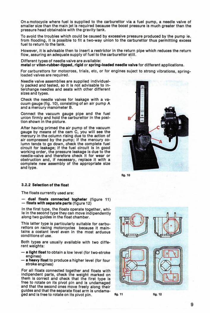
Check the needle valves for leakage with a vacuum gauge (fig . 10), consisting of an air pump A and a mercury manometer B.
Connect the vacuum gauge pIpe and the fuel unIon firmly and hold the carburettor in the position shown in the picture.
After having primed the air pump of the vacuum gauge by means of the cam C, you will see the mercury In the column rising due to the action of air compressed by the pump; If the mercury column tends to go down, check the complete fuel circuit for leakage; If the fuel circuit Is in good working order, the pressure leakage Is due to the needle-valve and therefore check It for wear or obstruction and, If necessary, replace It with a complete new assembly of the appropriate size and type.
3.2.2 Selection of the flo.t
The floats currently used are:
- du.1 flo.ts connected toghe'er (figure 11) - flo,ts with lep.rate.parts (figure 12)
In the first type, the floats operate together, whi-le In the second type they can move Indlpendently along two guides in the float chamber.
This latter type is particularly suitable for carburettors on racing motorcycles because it maintains a costant level even In the most arduous conditions of use.
Both types are usually available with two different weights:
- • light lIo.t to obtain a low level (for two-stroke engines)
- • heavy flo.t to produce a higher level (for four stroke engines)
For all floats connected together and floats with Indlpendent parts, check the weight marked on them is correct and check that the first type is free to rotate on Its pivot pin and Is undamaged and that the second ones move freely along their guides and that the separate float arm is undama-
fig. 10
ged and Is free to rotate on Its pivot pin . fig. 11
n
Ilg.12
9
10
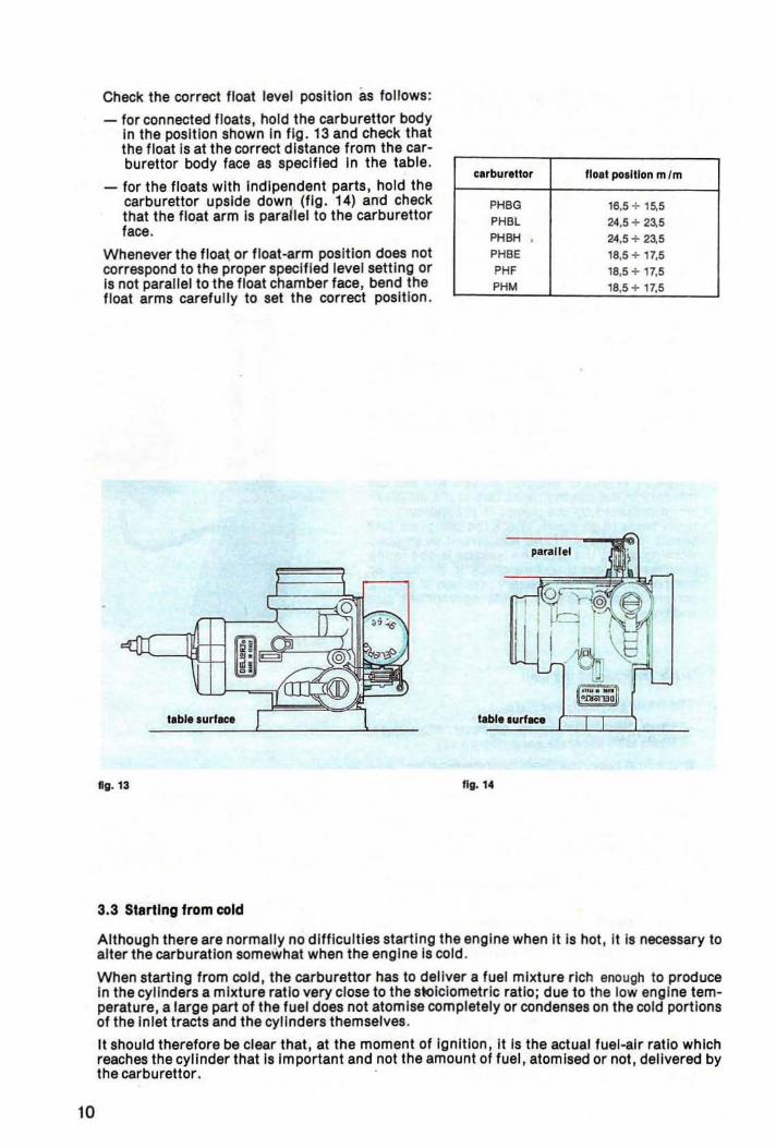
Check the correct float level pos ition as follows:
- for connected floats, hold the carburettor body in the position shown In fig . 13 and check that the float is at the correct distance from the carburettor body face as specified in the table .
- for the floats with indlpendent parts, hold the carburettor upside dow~ (fig. 14) and check that the flo.at arm Is parallel to the carburettor face.
Whenever the floa\ or f loat-arm position does not correspond to the proper spec ified level setting or Is not parallel to the float chamber face, bend the float arms carefully to set the correct posit ion .
'abl •• urlec.
10. 13
3.3 Starting from cold
carbur.Uor Iiolt po.lUon m 1m
PHBG 16,5 ;' 15.5 PHBl 24,5 + 23,5 PHBH 24,5;. 23,5 PHBE 18,5 ;' 17,5
PH' 18,5 ;. 17,5 PHM 18,5 ;' 17.5
tabl •• urlKe
fig. 14
Although there are normally no difficulties starting the engine when it is hot, It is necessary to alter the carburatlon somewhat when the engine Is cold .
When starting from cold , the carburettor has to deliver a fuel mixture rich enough to produce In the cylinders a mIxture ratIo very close to the stolc lometrlc ratIo; due to the low engine temperature, a large part of the fuel does not atom ise completely or condenses on the cold portions of the Inlet tracts and the cylinders themselves.
It should therefore be clear that, at the moment of Ignition , It Is the actual fuel-aIr ratio whIch reaches the cylinder that is important and not the amount of fuel, atomlsed or not, delivered by the carburettor . .
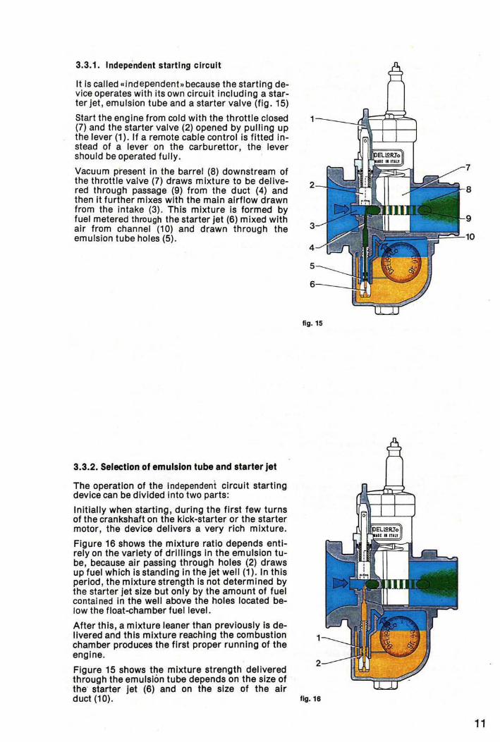
3.3.1. Independent starting circuit
It is called «independent .. because the starting device operates with its own circuit including a starter jet, emulsion tube and a starter valve (fig. 15)
Start the engine from cold with the throttle closed (7) and the starter valve (2) opened by pulling up the lever (1). If a remote cable control is fitted Instead of a lever on the carburettor, the lever should be operated fully .
Vacuum present in the barrel (8) downstream of the throttle valve (7) draws mixture to be delivered through passage (9) from the duct (4) and then it further mixes with the main airflow drawn from the intake (3) . This mixture is formed by fuel metered through the starter jet (6) mixed with air from channel (10) and drawn through the emulsion tube holes (5).
3.3.2. Selection 01 emulsion tube and starter jet
The operation of the independent circuit starting device can be divided into two parts:
Initially when starting, during the first few turns of the crankshaft on the kick-starter or the starter motor, the device delivers a very rich mixture.
Figure 16 shows the mixture ratio depends entirely on the variety of drlilings In the emulsion tube, because air passing through holes (2) draws up fuel which is standing in the jet well (1). In this period, the mixture strength is not determined by the starter Jet size but only by the amount of fuel contained in the well above the holes located below the float-chamber fuel level.
After this, a mixture leaner than previously is delivered and this mixture reaching the combustion chamber produces the first proper running of the engine.
Figure 15 shows the mixture strength delivered through the emulsion tube depends on the size of the' starter jet (6) and on the size of the air
fig. 15
d~"~. .,. 11
12
Thechannel size (4) is such that it creates an optimum vacuum in the starter valve chamber, at the emulsion tube otlet both for starting up and for the misture required by the engine for its running and ·warming up. Therefore, varyi ng the position or the size of the starter emulsion tube holes will change the amount of fuel delivered; the mixture ratio is controlled by the starter jet size and therefore a larger jet causes enrichment and vice-versa.
Difficulties in starting the engine can occur when this mixture is too rich or too lean and you can see this from the spark plugs. After some starting attempts, remove the spark plugs and, if these are wet, the mixture is too rich and you will therefore need an emulsion tube with holes hi· gher up.
Conversely, If the spark plugs are found to be dry, the mixture is too lean and an emulsion tube with holes lower down is therefore needed.
If the engine stalls when the engine is first started from cold before it has been running for at least a minute with the starting device on, you will need to reduce the starter jet size because of an over-rich mixture or increase it if the engine stalls because of a lean mixture.
Check that the starter valve closes completely afterwards to avoid any mixture blow-by which may later disturb the carburation.
Therefore check that with the starting device off , the control lever Is free to move a little on its pivot pin or that, where a rem ote cable control is fitted, the cable has at least 1-2 mm of free play.
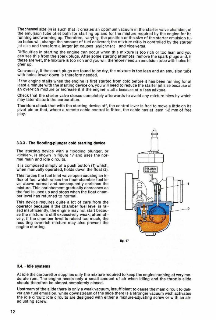
3.3.3 • The flooding-plunger cold starting device
The starting device with a flooding plunger, or «tickler», is shown in figure 17 and uses the normal main and idle circuits.
It Is composed simply of a push button (1) which , when manually operated, holds down the float (2).
This forces the fuel Inlet valve open causing an influx of fuel which raises the float chamber fuel level above normal and consequently enriches the mixture. This enrichement gradually decreases as the fuel is used up and stops when the float chamber level has returned to normal.
This device requires quite a lot of care from the operator because II the chamber fuel level Is raised Insufficiently, the engine may not start because the mixture is still excessively weak; alternatively, I"f the chamber level is raised too much, the resulting over-rich mixture may also prevent the engine starting.
3.4 .• Idle systems
fig. 11
DElLS!RJo • ... . If'"~
1
£-__ . 2
At idle the carburettor supplies only the mixture required to keep the engine running at very moderate rpm. The engine needs only a small amount of air when Idling and the throttle slide should therefore be almost completely closed.
Upstream of the slide there Is only a weak vacuum, insufficient to cause the main circuit to dell · ver any fuel emulsion, while downstream of the slide there Is a stronger vacuum wich activates the idle circuit; idle circuits are designed with either a mixture-adjusting screw or with an airadjusting screw.
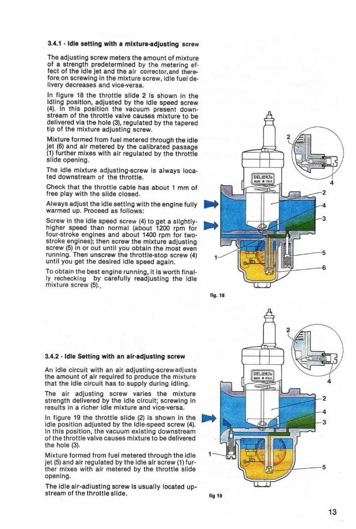
3.4.1 • Idle setting with a mixture·adJusting screw
The adjusting screw meters the amount of mixture of a strength predetermined by the metering effect of the Idle jet and the air corrector,and therefore.on screwing in the mixture screw, idle fuel de· livery decreases and vice-versa .
In figure 18 the throttle slide 2 is shown in the Idling position, adjusted by the idle speed screw (4). In this positton the vacuum present down· st ream of the throttle valve causes mixture to be delivered via the hole (3), regulated by the tapered tip of the mixture adjusting screw.
Mixture formed from fuel metered through the idle jet (6) and air metered by the calibrated passage (1) further mixes with air regulated by the throttle slide opening.
The Id le mixture adJusting-screw is always loca· ted downstream of the throttle.
Check that the throttle cable has about 1 mm of free play with the slide closed.
Always adjust the idle setting with the engine fully warmed up. Proceed as foll ows:
Screw in the Id le speed screw (4) to get a slightly· higher speed than normal (about 1200 rpm for four-stroke engines and about 1400 rpm for twostroke engines); then screw the mixture adjusting screw (5) In or out until you obtain the most even runn ing. Then unscrew the throttle·stop screw (4) until you get the desired Id le speed again.
To obtain the best engine running, it is worth final· Iy rechecking by carefu lly readjusting the Idle mixture screw (5) ..
3.4.2· Idle Sett ing with an alr·adjusting screw
An idle circuit with an air adjusting-screw adjusts the amount of air required to produce the mixture that the id le circuit has to supply during idling.
The air adjusting screw varies the mixture strength delivered by the Id le circuit; screwing In results in a richer idle mixture and vice-versa.
In figure 19 the throttle slide (2) is shown in the idle position adjusted by the id le-speed screw (4). In this position, the vacuum existing downstream of the throttle valve causes mixture to be delivered the hole (3).
Mixture formed from fuel metered through the idle jet (5) and air regulated by the Idle air screw (1) further mixes with air metered by the throttle slide opening.
The Id le air-adiustl ng screw is usually located upst ream of the throttle slide.
Iii!. 18
2
4
fig 19
13
14
Check that the throttle cable has about 1 mm free play when the slide is fully closed.
Always adjust the idle setting with the engine fully warm.
Screw in the idle-speed screw (4) to obtain a slightly·higher idling speed than normal (about 1200 rpm for a four·stroke engine or about 1400 rpm for a two-stroke); Then adjust the airadjusting screw (1) to obtain the most even running .
Then unscrew the idle-speed screw again until you obtain the normal idling speed.
Finally, to obtain the best engine running , it is worth recheckin'g by very carefully readjusting the air-adjusting screw.
3.4.3 - Selection of the correct size of idle jet
To select the proper size of idle jet , slowly open the throttle with the twistgrip (opening sgou ld not exceed a quarter throttle): a slow and uneven increase in rpm indicates that the idle jet is too small. This effect can also be observed when the idle mixture screw is open too much or when the idle air screw is closed too much and therefore not properly responsive to the engine's running.
If you observe smoke in the exhaust gas and a dull noise, it means that the idle jet size is too large; this can also occur when the mixture-adjusting screw Is screwed in too much and oversensitive or when the air-adjusting screw Is screwed out too much.
Usually with racing motorcycles, after having adjusted the idle as above, unscrew the idlespeed screw to allow the throttle to close completely so that you will obtain the maximum engi ne braking on cloSing the throttle. In this case however, do not readjust the mixture screw or airscrew setting because any further mixture screw closure or arr·screw opening may cause two· stroke engines to seize on the overrun.
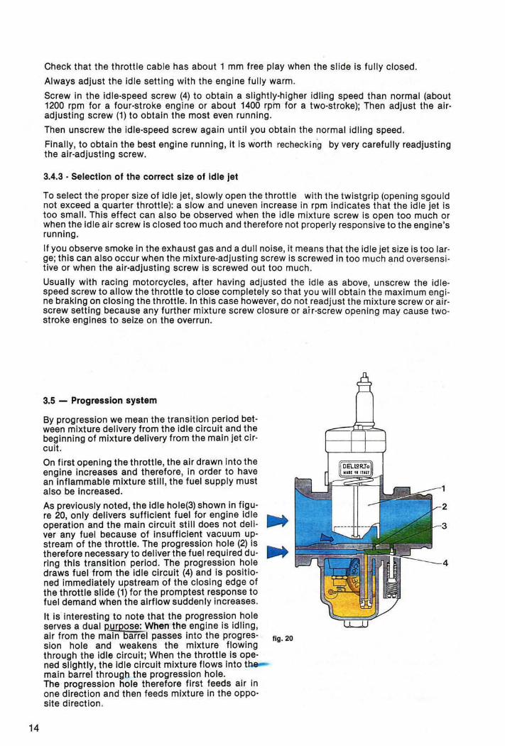
3.5 - Progression system
By progression we mean the transition period bet· ween mixture delivery from the Idle circuit and the beginning of mixture delivery from the main jet cir· cuit.
On first opening the throttle, the air drawn into the engine increases and therefore , in order to have an Inflammable mixture stili, the fuel supply must also be Increased.
As previously noted, the Idle hole(3) shown in figu-re 20, only delivers sufficient fuel for engine Idle ........ operation and the main circuit still does not dell- .....,.. ver any fuel because of insufficient vacuum upstream of the throttle. The progression hole (2) is therefore necessary to deliver the fuel required du- .. ring this transition period. The progression hole draws fuel from the idle circuit (4) and is positio-ned immediately upstream of the closing edge of the throttle slide {11 for the promptest response to fuel demand when the airflow suddenly increases.
It Is interesting to note that the progression hole serves a dual Rurpose: When the engine is idling, air from the main barrel passes Into the progres- fig. 20 sian hole and weakens the mixture flowing through the idle circuit; When the throttle is ope-ned slightly, the idle circuit mixture flows into the--main barrel througb the progression hole. The progressIon hole therefore first feeds air In one dIrection and then feeds mixture in the opposite direction.
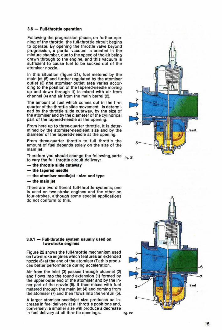
3.6 - Full·throttle operation
Following the progression phase, on further ope· nlng of the throttle, the full ·throttle circuit begins to operate. By opening the throttle valve beyond progression, a part ial vacuum Is created In the mixture chamber, due to the speed of the air bel n~ drawn through to the engine, and this vacuum is sufficient to cause fuel to be sucked out at the atomiser nozzle.
In th is situation (flgure 21), fuel metered by the main Jet (5) and further regulated by the atomlser outlet (3) (the atomlser out let area varies according to the pOSition of the tapered·needle moving up and down through It) Is mixed with ai r from channel (4) and air from the main barrel (2).
The amount of fuel which comes out In the flrst quarter of the throttle slide movement is determl · ned by the throttle slide cutaway, by the size of the atomlser and by the diameter of the cylindrical part of the tapered·needle at the opening.
From here up to three-quarter throttle, it is determined by the atomlser-needleJet size and by the diameter of the tapered·needle at the opening.
From three-quarter throttle to full throttle the amount of fuel depends solely on the size of the main Jet.
Therefore you should change the following, parts to vary the full throttle olrcult delivery: - the throttle .lId, cut.way - the tapered needl. - the .toml~lr·needl'J't .• lzl and tYPI - the main jlt There are two different full·throttle systems; one is used on two·stroke engines and the other on four-st rokes, although some special applications do not conform to this .
3.8.1 - Full·throttle system usually used on two·stroke engln81
Figure 22 shows the full-throttle mechanism used on two·stroke engines which features an extended nozzle (6) at the end of the atomlser (7); this produ· ces better performance during acceleration .
Air from the Inlet (3) passes through channel (2) and flows into the round extension (1) formed by the upper outer end of the atomiser and by the In· ner part of the nozzle (6). It then mixes with fuel metered thrQugh the main jet (4) and coming from the atomlser (7) and then flows Into the venturI (5).
A larger atomlser·needleJet size produces an in· crease in fuel delivery at all throttle positions and , conversely, a smaller size wl1l produce a decrease
IIg. 21
In fuel delivery at all throttle openings. fig. 22
15
16
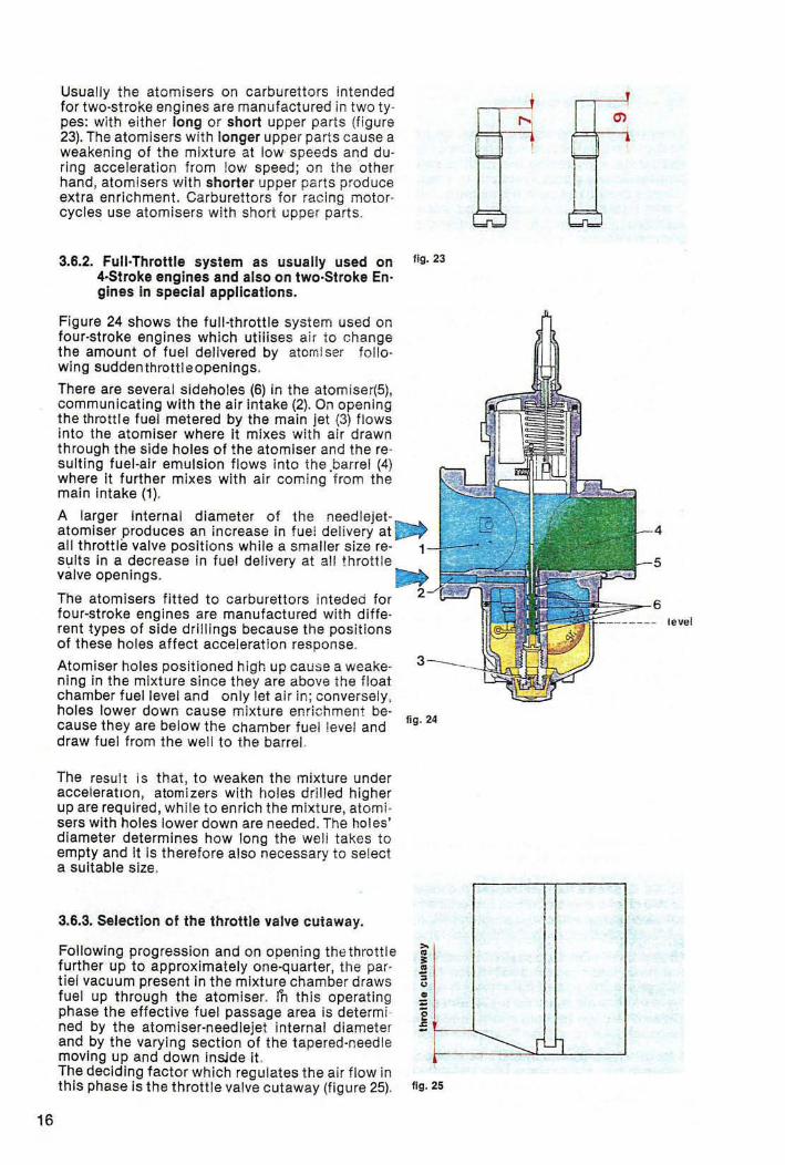
Usually the atomisers on carburettors intended for two-stroke engines are manufactured in two types: with either long or short upper parts (f igure 23). The atomisers with longer upper parts cause a weakening of the mixture at low speeds and during acceleration from low speed; on the other hand, atomisers wilh shorter upper parts produce extra enrichment. Carburettors for racing motorcycles use atomisers with short upper parts .
3.6.2. Full-Throttle system as usually used on 4·Stroke engines and also on two-Stroke Engines In speeial applications.
Figure 24 shows the full-throttle system used on four·stroke engines which utilises air to change the amount of fuel delivered by atomlser foliowing suddenthrottleopenings.
There are several sideholes (6) in the atomiser(5j, commun icating with the air intake (2). On opening the throttle fuel metered by the main Jet (3) flows into the atomiser where it mixes with air drawn through the side holes 01 the atomiser and the reo suiting fuel-ai r emulsion flows into the .barrel (4) where it further mixes with air coming from the main Intake (1).
Ilg_ 23
A larger Internal diameter of the needleJetatomiser produces an Increase in fuel del ivery at . all throttle valve positions whi le a smaller size re- 1-1-suits In a decrease in fuel delivery at all throttle valve openings _
The atomisers fitted to carburettors Inteded for four-stroke engines are manufactured with diffe-rent types of side drillings because the positions of these holes affect acceleration response_
Atomiser holes positioned high up cause a weakening in the mixture since they are above the lIoat chamber fuel level and only let air in ; conversely, holes lower down cause mixture enrichment because they are below the chamber fuel level and draw fuel from the well to the barrel.
The resu lt is that, to weaken the mixture under acceleratIOn, atomi zers with holes drilled higher up are requ ired , while to enrich the mixture, atomi· sers with holes lower down are needed. The holes' diameter determines how long the Well! takes to empty and It is therefore also necessary to select a suitable size.
3.6.3. Selection at the throttle valve cutaway.
Fallowing progression and on opening the throttle fUrther up to approximately one·quarter, the partiel vacuum present in the mixture chamber draws fuel up through the atomiser. in th is operating phase the effective fuel passage area is determi ned by the atomiser'needleJet internal diameter and by the varying section of the tapered-needle moving up and down Inside it. The deciding factor wh ich regu lates the air flow In this phase is the throttle valve cutaway (figure 25).
3
fig . 24
IIg. 25
leval
-------- _ r ~
A small cutaway creates a greater vacuum and consequently causes a larger amount of fuel to be drawn up through the atomiser ; on the other hand, a larger cutaway would lower the vacuum and therefore reduce the fuel delivered. Because of this, fitti ng a .lower slide cutaway reo suits in enrichment and vice versa.
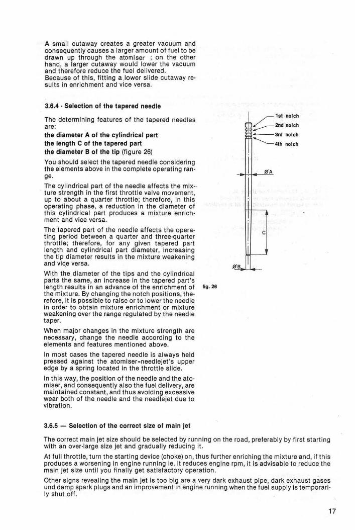
3.6.4 . Selection of the tapered needle
The determining features of the tapered needles are: the diameter A of the cylindrical part the length C of the tapered part the diameter B of the tip (figure 26)
You should select the tapered needle considering the elements above in the complete operating ran· ge.
The cylindrical part of the needle affects the mix·· t ure strength In the first th rottle valve movement, up to about a quarter th rottle; therefore, in this operating phase, a reduction in the diameter of this cyli ndrical part produces a mixture enrich· ment and vice versa.
The tapered part of the needle affects the opera· t lng period between a quarter and three·quarter throttle; therefo re, for any given tapered part length and cylindrical part diameter, Increas ing the tip diameter results in the mixture weakening and vic,e versa.
With the diameter of the ti ps and the cyli ndrical parts the same, an increase in the tapered part 's length resu lts In an advance of the enrichment of IIg.26 the mixture. By changing the notch positions, the· refore, It Is possible to raise or to lower the needle in order to obtain mixture enrichment or mixtu re weaken ing over the range regulated by the needle taper.
When major changes in the mixtu re strength are necessary, change the needle according to the elements and features mentioned above.
In most cases the tapered needle Is always held pressed against the atomiser.needleJet's upper edge by a spring located In the throttle slide.
In this way, the position of the needle and the ato· miser, and consequently also the fuel delivery, are maintained constant , and thus avoiding excessive wear both of the needle and the needlejet due to vibration.
3.6.5 - Selection of the correct size of main jet
ge
~1st nolch
::::-- 2nd nolch
• 3rd nolch
---- 4th nolch
flfA
c
The correct main jet size should be se.lected by running on the road, preferably by first starting with an over·large size jet and gradua lly reducing it.
At full throttle , turn the start ing device (choke) on, thus further enriching the mixture and, i f th is produces a worsening in engine running Ie. it reduces eng ine rpm, it Is advisable to reduce the main jet size until you final ly get sat isfactory operation.
Other signs revealing the main Jet Is too big are a very dark exhaust pipe, dark exhaust gases und damp spark plugs and an improvement in eng ine running when the fuel supply is temporari· Iy shut off .
17
18
In a case where too small a main jet has been fitted at first, and the running with the choke on makes a noticeable improvement , you should increase the main jet size until the conditions mentioned above occur.
In selecting the correct main jet, the engine running temperature should be taken Into conside· ration, quite apart from Increases in power and top speed, because lean mixtures cause higher running temperatures. .
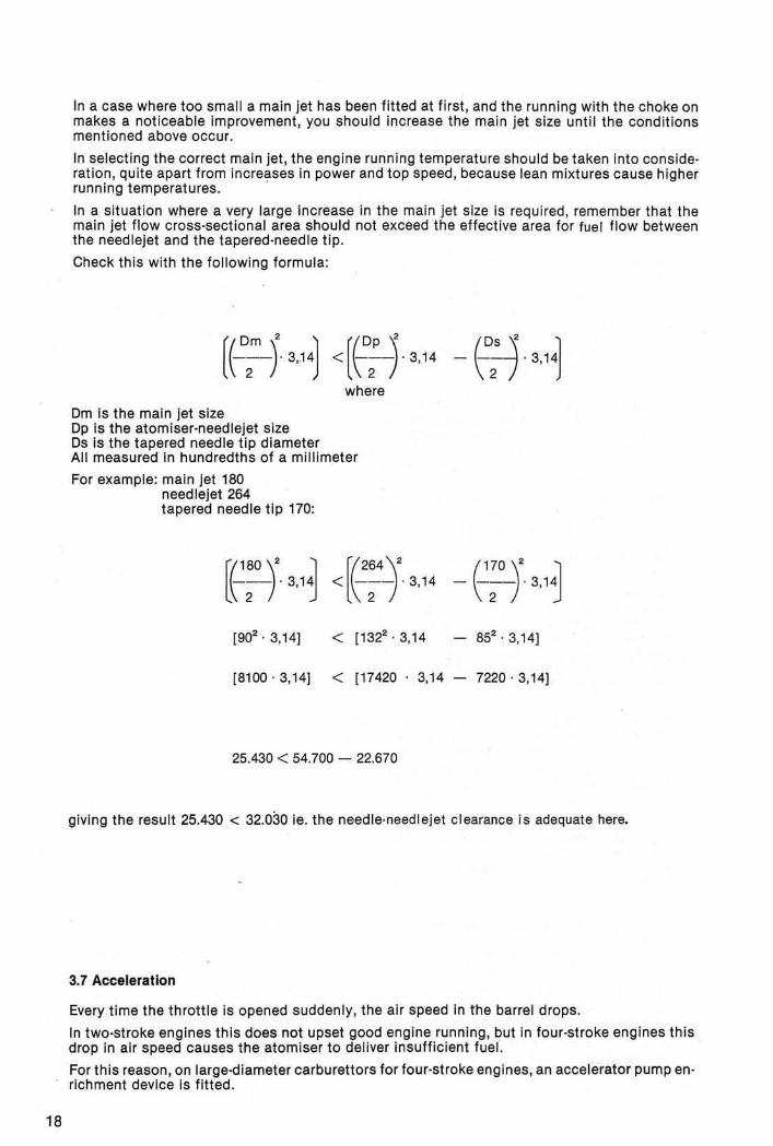
In a situation where a very large increase in the main jet size is required , remember that the main jet flow cross·sectional area should not exceed the effective area for fuel flow between the needlejet and the tapered·need le tip.
Check this with the following formula:
where
Om Is the main jet size Op Is the atomiser·needlejet size Os is the tapered needle tip diameter All measured in hundredths of a mi llimeter
For example: main jet 180 needlejet 264 tapered needle tip 170:
[(180 \' :1 r(264 \' l\-2-r 3,1~ <l\;-;' 3,14
[902. 3,14) < 11322
• 3,14
[8100 , 3,14) < 117420 3,14
25.430 < 54.700 - 22.670
(HO\, ~ - \-2-r 3, 1~
852• 3,14)
7220 · 3,14]
giving the result 25.430 < 32.030 ie. the needle·needlejet clearance is adequate here.
3,7 Acceleration
Every time the throttle is opened suddenly, the air speed In the barrel drops.
In two·stroke engines this does not upset good engine running , but in four·stroke engines this drop in air speed causes the atomiser to deliver insufficient fuel.
For this reason , on large·diameter carburettors for four·stroke engines, an accelerator pump en· richment device is fitted.
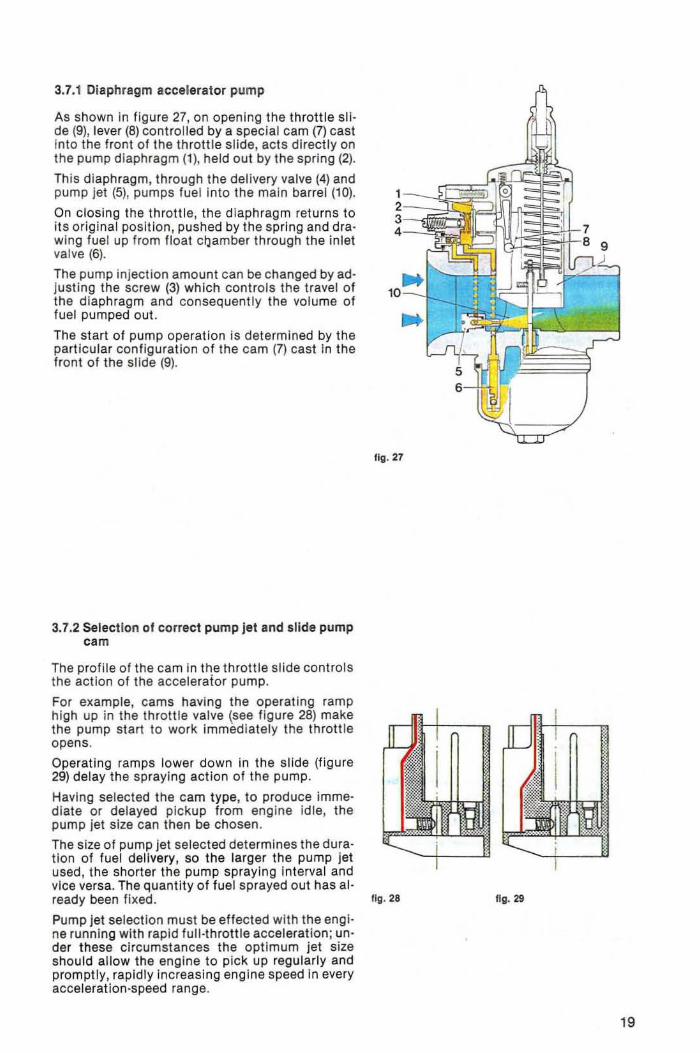
3.7.1 Diaphragm accelerator pump
As shown in figure 27, on opening the throttle slide (9), lever (8) controlled by a special cam (7) cast Into the front of the throttle slide, acts directly on the pump diaphragm (1 ), held out by the spring (2).
This diaphragm, through the delivery valve (4) and pump jet (5), pumps fuel into the main barrel (10).
On closing the throttle. the diaphragm returns to its original position, pushed by the spring and drawing fuel up from floal clJamber through the inlet valve (6).
The pump injection amounl can be Changed by adjusting the screw (3) which cont rols the travel of the diaphragm and consequently the volume of fuel pumped out.
The start of pump operation is determined by the particular configuration of the cam (7) cast in the front of the slide (9).
3.7.2 Selection of correct pump jet and slide pump cam
The profile of the cam in the throttle slide controls the action of the accelerator pump.
For example, cams having the operating ramp high up in the throttle valve (see f igure 28) make the pump start to work immediately the thrott le opens.
Operating ramps lower down in the slide (figure 29) delay the spraying action of the pump.
Having selected the cam type, to produce immediate or delayed pickup from eng ine idle, the pump jet size can then be chosen.
The size of pump jet selected determines the duration of fuel delivery, so the larger the pump jet used, the shorter the pump spraying Interval and vice versa. The quantity of fuel sprayed out has al -
Iig. 27
ready been fixed. Ilg. 28
Pump Jet selection must be effected with the engi-ne running with rapid full-thrott le acceleration; un-der these circumstances the opt imum jet size should allow the engine to pick up regularly and promptly, rapidly increasing engine speed in every acceleration -speed range .
Ilg. 29
19
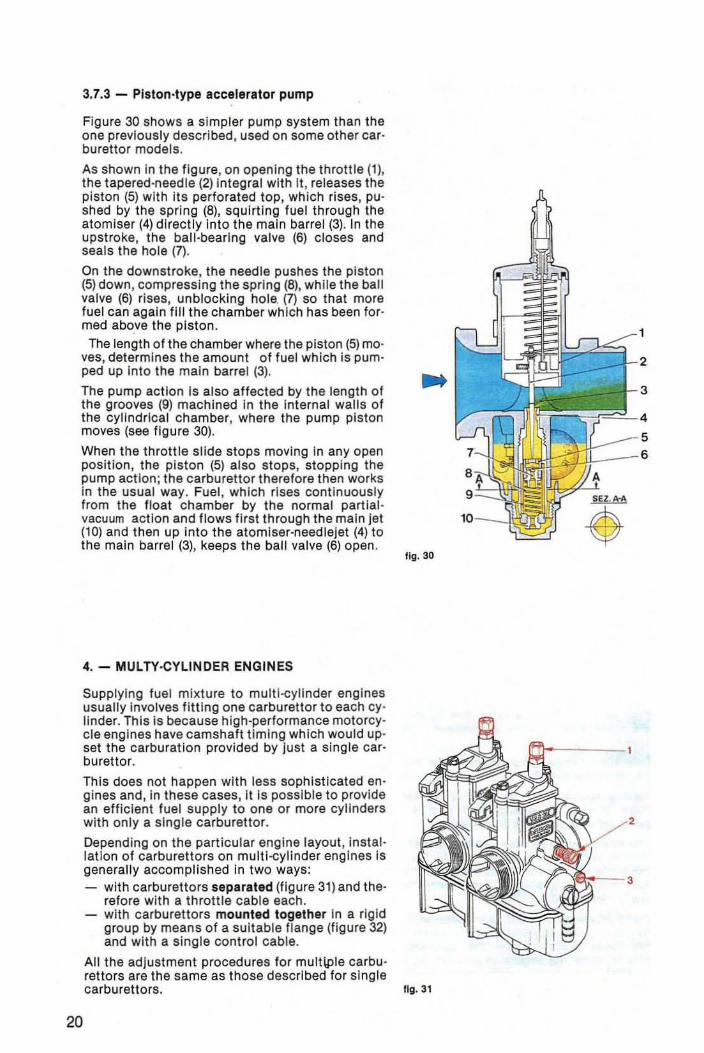
3,7.3 - Piston,type accelerator pump
Figure 30 shows a simpler pump system than the one previously described, used on some other car· burettor models.
As shown In the figure, on opening the throttle (1), the tapered-needle (2) integral with It , releases the piston (5) with Its perforated top, which rises, pu· shed by the spring (8), squirting fue l through the atomiser (4) directly Into the main barrel (3). In the upstroke, the ball-bearing valve (6) closes and seals the hole (7).
On the downstroke, the needle pushes the piston (5) down, compressing the spring (8), while the ball valve (6) rises, unblocking hole. (7) so that more fuel can again fi ll the chamber which has been formed abo.ve the piston . The length of the chamber where the piston (5) mo
ves, determines the amount of fuel which is pumped up into the main barrel (3).
The pump action Is also affected by the length of the grooves (9) machined In the Internal walls of the cylindrical chamber, where the pump piston moves (see figure 30).
When the throttle slide stops moving In any open position, the piston (5) also stops, stopping the pump act ion; the carburettor therefore then works in the usual way. Fuel , wh ich rises cont inuously from the f loat chamber by the normal partial· vacuum action and flows f irst through the main Jet (10) and then up Into the atomlser-need lejet (4) to the main barrel (3), keeps the ball valve (6) open .
4. - MULTY·CYLINDER ENGINES
Supplying fuel mixture to mulU-cyllnder engines usually Involves fitting one carburettor to each cy· linder. This Is because high·performance motorcy· cle engines have camshaft timing which wou ld up· set the carburatlon provided by Just a single car· burettor.
This does not happen with less sophisticated en· gines and, in these cases, it is possible to provide an efficient fuel supp ly to one or more cylinders with only a slng[e carburettor.
Depending on the part icular engine layout , instal · lalion of carburettors on multl ·cylinder engines is generally accomplished In Iwo ways: - with carburettors separated (figure 31) and the
refore with a throttle cable each. - with carburettors mounted together in a rig id
group by means of a su itable flange (figure 32) and with a single cont rol cable.
All the adjustment procedures for multiPle carbu· rettors are the same as t hose described for single
fig . 30
carburettors. Ilg.31
20
~-3
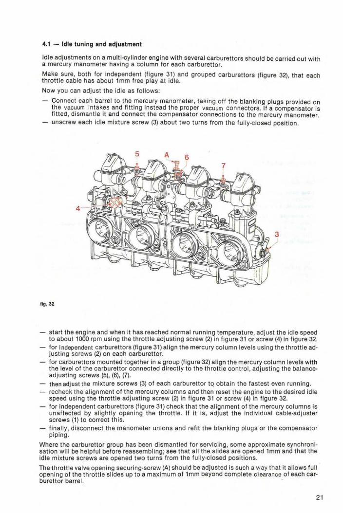
4.1 - Idle tuning and adjustment
Idle adjustments on a multl-cyllnder engine with several carburettors should be carried out with a mercury manometer having a column for each carburettor.
Make sure, both for independent (figure 31) and grouped carburettors (figure 32), that each throttle cable has about l mm free play at Idle.
Now you can adjust the Idle as follows:
Connect each barrel to the mercury manometer, taking off the blanking plugs provided on the vacuum in takes and fitting instead the proper vacuum connectors. II a compensator Is fitted , dismantle it and connect the compensator connections to the mercury manometer. unscrew each Idle mixture screw (3) about two turns from the fully-closed positlon.
3
fig. 32
start the engine and when It has reached normal running temperature , adjust the idle speed to about 1000 rpm using the throttle adjusting screw (2) in figure 31 or screw (4) In figure 32. for independent carburet tors (figure 31) align the mercury column levels using the thrott le ad· justing screws (2) on each carburettor. for carburettors mounted together in a group (f igure 32) align the mercury column levels with the level of the carburettor connected directly to the throttle control, adjusting the balanceadjusting screws (5), (6), (7). then adjust the mixture screws (3) of each carburettor tQ obtain the fastest even running. recheck the alignment of the mercury columns and then reset the engine to the desired Idle speed using the throttle adjusting screw (2) in figure 31 or screw (4) In figure 32. for Independent carburettors (figure 31) check that the alignment 01 the mercury columns is unaffected by slightly opening the throttle. if it Is, adjust the individual cable-adjuster screws (1) to correct this. finally, disconnect the manometer unions and refit the blanking plugs or the compensator piplng _
Where the carburettor group has been dismantled for servicing, some approximate synchronisation will be helpful before reassembling; see that alt the slides are opened lmm and that the idle mixture screws are opened two turns from the fully-closed pOSitions.
The throttle valve opening securing-screw (A) should be adjusted Is such a way that it allows full opening of the throttle slides up to a maximum of lmm beyond complete clearance of each car· burettor barrel.
21
22
5. - FACTORS WHICH CAN AFFECT CARBURATION
In some cases, carburatlon which has been properly set up in particular conditions can then be upset by certain factors ie. a change of fuel used a change in atmospheric pressure a change in air temperature
5.1 - Change of fuel
When a different fuel other than commercia l petrol is used, it is necessary to estimatetheorelically the new stoiclometrlc mixture ratio and consequently change all the jet sizes to suit.
If the stolclometric mixture ratio decreases, larger jets are required and vice versa. Any such changes should, .of course, be made on a percentage basis ie. when the stoiciomet ric ratio in· creases by a certain percentage, the Jet sizes should be reduced by that percentage.
For example, if commercial petrol (stolciometric ratio 14.5) Is replaced by methyl alcohol (me· thanol , with chemical formula CH30H . stoiciometric ratio 6.5) the jet sizes should be increased by about 50% ie. double the flow rate. If fuel consisting of 25% pet rol and 75% methanol is used, jet sizes should all be Increased by 30%; with fuel composed of 50% petrol and 50% me· thanol, the jet sizes need only be increased by 18% compared to when using straight petrol.
You should also replace the needlevalves, Increasing the seat sizes accordingly .
When using special fuels such as methanol , it is very Important that all the component mate· rials of the carburettors have been treated , wherever necessary, to resist chemical attack. For example, nylon components should be removed, and rep laced by other parts res istant to the new fuel.
5.2 - Changes in atmospheric pressure and In air temperature
Variations in pressure or temperature cause a change In the air density and consequently a change in the fuel·air ratio and further tuning may therefore become necessary.
A decrease in atmospheric pressure with consequent decrease in air density causes a mixture enrichment and smaller jets wi l l therefore be required.
Altitude variations also produce changes in the carburatlon and Ihey too cause changes in the air density ; prolonged use of a vehicle at an altitude higher than 1500 metres, the carburatlon of which was originally set up for operation at around sea level, would requi re a change of jet sizes in proportion to the pressure change.
In this case too , a decrease in pressure should be compensated by a reduct ion of the jet sizes.
Furthermore, a lowering of air temperature produces an Increase in air density and consequen· tly a mixtu re weakening; therefore an increase in the jet sizes is required.
Summarising, we can say that any decrease in air pressure, any increase in altitude or in air temperature should be compensatea for by a decrease In the jet sizes.
Conversely, any increase in pressure or any decrease In altitude or in temperature should be compensated by an increase In the jet sizes.